JP5886357B2 - Open space, decompression therapy device and system - Google Patents
Open space, decompression therapy device and systemDownload PDFInfo
- Publication number
- JP5886357B2 JP5886357B2JP2014085090AJP2014085090AJP5886357B2JP 5886357 B2JP5886357 B2JP 5886357B2JP 2014085090 AJP2014085090 AJP 2014085090AJP 2014085090 AJP2014085090 AJP 2014085090AJP 5886357 B2JP5886357 B2JP 5886357B2
- Authority
- JP
- Japan
- Prior art keywords
- leg
- shaped
- members
- manifold
- capsule
- Prior art date
- Legal status (The legal status is an assumption and is not a legal conclusion. Google has not performed a legal analysis and makes no representation as to the accuracy of the status listed.)
- Active
Links
Images


Classifications
- A—HUMAN NECESSITIES
- A61—MEDICAL OR VETERINARY SCIENCE; HYGIENE
- A61M—DEVICES FOR INTRODUCING MEDIA INTO, OR ONTO, THE BODY; DEVICES FOR TRANSDUCING BODY MEDIA OR FOR TAKING MEDIA FROM THE BODY; DEVICES FOR PRODUCING OR ENDING SLEEP OR STUPOR
- A61M1/00—Suction or pumping devices for medical purposes; Devices for carrying-off, for treatment of, or for carrying-over, body-liquids; Drainage systems
- A61M1/90—Negative pressure wound therapy devices, i.e. devices for applying suction to a wound to promote healing, e.g. including a vacuum dressing
- A61M1/96—Suction control thereof
- A61M1/964—Suction control thereof having venting means on or near the dressing
- A—HUMAN NECESSITIES
- A61—MEDICAL OR VETERINARY SCIENCE; HYGIENE
- A61M—DEVICES FOR INTRODUCING MEDIA INTO, OR ONTO, THE BODY; DEVICES FOR TRANSDUCING BODY MEDIA OR FOR TAKING MEDIA FROM THE BODY; DEVICES FOR PRODUCING OR ENDING SLEEP OR STUPOR
- A61M1/00—Suction or pumping devices for medical purposes; Devices for carrying-off, for treatment of, or for carrying-over, body-liquids; Drainage systems
- A—HUMAN NECESSITIES
- A61—MEDICAL OR VETERINARY SCIENCE; HYGIENE
- A61B—DIAGNOSIS; SURGERY; IDENTIFICATION
- A61B17/00—Surgical instruments, devices or methods
- A61B17/0057—Implements for plugging an opening in the wall of a hollow or tubular organ, e.g. for sealing a vessel puncture or closing a cardiac septal defect
- A—HUMAN NECESSITIES
- A61—MEDICAL OR VETERINARY SCIENCE; HYGIENE
- A61F—FILTERS IMPLANTABLE INTO BLOOD VESSELS; PROSTHESES; DEVICES PROVIDING PATENCY TO, OR PREVENTING COLLAPSING OF, TUBULAR STRUCTURES OF THE BODY, e.g. STENTS; ORTHOPAEDIC, NURSING OR CONTRACEPTIVE DEVICES; FOMENTATION; TREATMENT OR PROTECTION OF EYES OR EARS; BANDAGES, DRESSINGS OR ABSORBENT PADS; FIRST-AID KITS
- A61F13/00—Bandages or dressings; Absorbent pads
- A61F13/00987—Apparatus or processes for manufacturing non-adhesive dressings or bandages
- A—HUMAN NECESSITIES
- A61—MEDICAL OR VETERINARY SCIENCE; HYGIENE
- A61F—FILTERS IMPLANTABLE INTO BLOOD VESSELS; PROSTHESES; DEVICES PROVIDING PATENCY TO, OR PREVENTING COLLAPSING OF, TUBULAR STRUCTURES OF THE BODY, e.g. STENTS; ORTHOPAEDIC, NURSING OR CONTRACEPTIVE DEVICES; FOMENTATION; TREATMENT OR PROTECTION OF EYES OR EARS; BANDAGES, DRESSINGS OR ABSORBENT PADS; FIRST-AID KITS
- A61F13/00—Bandages or dressings; Absorbent pads
- A61F13/01—Non-adhesive bandages or dressings
- A61F13/01021—Non-adhesive bandages or dressings characterised by the structure of the dressing
- A61F13/01025—Non-adhesive bandages or dressings characterised by the structure of the dressing made of a single layer
- A—HUMAN NECESSITIES
- A61—MEDICAL OR VETERINARY SCIENCE; HYGIENE
- A61F—FILTERS IMPLANTABLE INTO BLOOD VESSELS; PROSTHESES; DEVICES PROVIDING PATENCY TO, OR PREVENTING COLLAPSING OF, TUBULAR STRUCTURES OF THE BODY, e.g. STENTS; ORTHOPAEDIC, NURSING OR CONTRACEPTIVE DEVICES; FOMENTATION; TREATMENT OR PROTECTION OF EYES OR EARS; BANDAGES, DRESSINGS OR ABSORBENT PADS; FIRST-AID KITS
- A61F13/00—Bandages or dressings; Absorbent pads
- A61F13/01—Non-adhesive bandages or dressings
- A61F13/01034—Non-adhesive bandages or dressings characterised by a property
- A—HUMAN NECESSITIES
- A61—MEDICAL OR VETERINARY SCIENCE; HYGIENE
- A61F—FILTERS IMPLANTABLE INTO BLOOD VESSELS; PROSTHESES; DEVICES PROVIDING PATENCY TO, OR PREVENTING COLLAPSING OF, TUBULAR STRUCTURES OF THE BODY, e.g. STENTS; ORTHOPAEDIC, NURSING OR CONTRACEPTIVE DEVICES; FOMENTATION; TREATMENT OR PROTECTION OF EYES OR EARS; BANDAGES, DRESSINGS OR ABSORBENT PADS; FIRST-AID KITS
- A61F13/00—Bandages or dressings; Absorbent pads
- A61F13/02—Adhesive bandages or dressings
- A—HUMAN NECESSITIES
- A61—MEDICAL OR VETERINARY SCIENCE; HYGIENE
- A61F—FILTERS IMPLANTABLE INTO BLOOD VESSELS; PROSTHESES; DEVICES PROVIDING PATENCY TO, OR PREVENTING COLLAPSING OF, TUBULAR STRUCTURES OF THE BODY, e.g. STENTS; ORTHOPAEDIC, NURSING OR CONTRACEPTIVE DEVICES; FOMENTATION; TREATMENT OR PROTECTION OF EYES OR EARS; BANDAGES, DRESSINGS OR ABSORBENT PADS; FIRST-AID KITS
- A61F13/00—Bandages or dressings; Absorbent pads
- A61F13/05—Bandages or dressings; Absorbent pads specially adapted for use with sub-pressure or over-pressure therapy, wound drainage or wound irrigation, e.g. for use with negative-pressure wound therapy [NPWT]
- A—HUMAN NECESSITIES
- A61—MEDICAL OR VETERINARY SCIENCE; HYGIENE
- A61M—DEVICES FOR INTRODUCING MEDIA INTO, OR ONTO, THE BODY; DEVICES FOR TRANSDUCING BODY MEDIA OR FOR TAKING MEDIA FROM THE BODY; DEVICES FOR PRODUCING OR ENDING SLEEP OR STUPOR
- A61M1/00—Suction or pumping devices for medical purposes; Devices for carrying-off, for treatment of, or for carrying-over, body-liquids; Drainage systems
- A61M1/90—Negative pressure wound therapy devices, i.e. devices for applying suction to a wound to promote healing, e.g. including a vacuum dressing
- A61M1/91—Suction aspects of the dressing
- A61M1/912—Connectors between dressing and drainage tube
- A—HUMAN NECESSITIES
- A61—MEDICAL OR VETERINARY SCIENCE; HYGIENE
- A61M—DEVICES FOR INTRODUCING MEDIA INTO, OR ONTO, THE BODY; DEVICES FOR TRANSDUCING BODY MEDIA OR FOR TAKING MEDIA FROM THE BODY; DEVICES FOR PRODUCING OR ENDING SLEEP OR STUPOR
- A61M1/00—Suction or pumping devices for medical purposes; Devices for carrying-off, for treatment of, or for carrying-over, body-liquids; Drainage systems
- A61M1/90—Negative pressure wound therapy devices, i.e. devices for applying suction to a wound to promote healing, e.g. including a vacuum dressing
- A61M1/91—Suction aspects of the dressing
- A61M1/915—Constructional details of the pressure distribution manifold
- A—HUMAN NECESSITIES
- A61—MEDICAL OR VETERINARY SCIENCE; HYGIENE
- A61M—DEVICES FOR INTRODUCING MEDIA INTO, OR ONTO, THE BODY; DEVICES FOR TRANSDUCING BODY MEDIA OR FOR TAKING MEDIA FROM THE BODY; DEVICES FOR PRODUCING OR ENDING SLEEP OR STUPOR
- A61M1/00—Suction or pumping devices for medical purposes; Devices for carrying-off, for treatment of, or for carrying-over, body-liquids; Drainage systems
- A61M1/90—Negative pressure wound therapy devices, i.e. devices for applying suction to a wound to promote healing, e.g. including a vacuum dressing
- A61M1/91—Suction aspects of the dressing
- A61M1/916—Suction aspects of the dressing specially adapted for deep wounds
- A—HUMAN NECESSITIES
- A61—MEDICAL OR VETERINARY SCIENCE; HYGIENE
- A61M—DEVICES FOR INTRODUCING MEDIA INTO, OR ONTO, THE BODY; DEVICES FOR TRANSDUCING BODY MEDIA OR FOR TAKING MEDIA FROM THE BODY; DEVICES FOR PRODUCING OR ENDING SLEEP OR STUPOR
- A61M27/00—Drainage appliance for wounds or the like, i.e. wound drains, implanted drains
- A—HUMAN NECESSITIES
- A61—MEDICAL OR VETERINARY SCIENCE; HYGIENE
- A61B—DIAGNOSIS; SURGERY; IDENTIFICATION
- A61B17/00—Surgical instruments, devices or methods
- A61B17/0057—Implements for plugging an opening in the wall of a hollow or tubular organ, e.g. for sealing a vessel puncture or closing a cardiac septal defect
- A61B2017/00575—Implements for plugging an opening in the wall of a hollow or tubular organ, e.g. for sealing a vessel puncture or closing a cardiac septal defect for closure at remote site, e.g. closing atrial septum defects
- A—HUMAN NECESSITIES
- A61—MEDICAL OR VETERINARY SCIENCE; HYGIENE
- A61B—DIAGNOSIS; SURGERY; IDENTIFICATION
- A61B17/00—Surgical instruments, devices or methods
- A61B17/0057—Implements for plugging an opening in the wall of a hollow or tubular organ, e.g. for sealing a vessel puncture or closing a cardiac septal defect
- A61B2017/00646—Type of implements
- A—HUMAN NECESSITIES
- A61—MEDICAL OR VETERINARY SCIENCE; HYGIENE
- A61B—DIAGNOSIS; SURGERY; IDENTIFICATION
- A61B17/00—Surgical instruments, devices or methods
- A61B17/0057—Implements for plugging an opening in the wall of a hollow or tubular organ, e.g. for sealing a vessel puncture or closing a cardiac septal defect
- A61B2017/00676—Implements for plugging an opening in the wall of a hollow or tubular organ, e.g. for sealing a vessel puncture or closing a cardiac septal defect promotion of self-sealing of the puncture
- A—HUMAN NECESSITIES
- A61—MEDICAL OR VETERINARY SCIENCE; HYGIENE
- A61F—FILTERS IMPLANTABLE INTO BLOOD VESSELS; PROSTHESES; DEVICES PROVIDING PATENCY TO, OR PREVENTING COLLAPSING OF, TUBULAR STRUCTURES OF THE BODY, e.g. STENTS; ORTHOPAEDIC, NURSING OR CONTRACEPTIVE DEVICES; FOMENTATION; TREATMENT OR PROTECTION OF EYES OR EARS; BANDAGES, DRESSINGS OR ABSORBENT PADS; FIRST-AID KITS
- A61F13/00—Bandages or dressings; Absorbent pads
- A61F13/01—Non-adhesive bandages or dressings
- A61F13/01021—Non-adhesive bandages or dressings characterised by the structure of the dressing
- A61F13/01029—Non-adhesive bandages or dressings characterised by the structure of the dressing made of multiple layers
- A—HUMAN NECESSITIES
- A61—MEDICAL OR VETERINARY SCIENCE; HYGIENE
- A61F—FILTERS IMPLANTABLE INTO BLOOD VESSELS; PROSTHESES; DEVICES PROVIDING PATENCY TO, OR PREVENTING COLLAPSING OF, TUBULAR STRUCTURES OF THE BODY, e.g. STENTS; ORTHOPAEDIC, NURSING OR CONTRACEPTIVE DEVICES; FOMENTATION; TREATMENT OR PROTECTION OF EYES OR EARS; BANDAGES, DRESSINGS OR ABSORBENT PADS; FIRST-AID KITS
- A61F13/00—Bandages or dressings; Absorbent pads
- A61F13/01—Non-adhesive bandages or dressings
- A61F13/01034—Non-adhesive bandages or dressings characterised by a property
- A61F13/01038—Flexibility, stretchability or elasticity
- A—HUMAN NECESSITIES
- A61—MEDICAL OR VETERINARY SCIENCE; HYGIENE
- A61M—DEVICES FOR INTRODUCING MEDIA INTO, OR ONTO, THE BODY; DEVICES FOR TRANSDUCING BODY MEDIA OR FOR TAKING MEDIA FROM THE BODY; DEVICES FOR PRODUCING OR ENDING SLEEP OR STUPOR
- A61M1/00—Suction or pumping devices for medical purposes; Devices for carrying-off, for treatment of, or for carrying-over, body-liquids; Drainage systems
- A61M1/90—Negative pressure wound therapy devices, i.e. devices for applying suction to a wound to promote healing, e.g. including a vacuum dressing
- A61M1/98—Containers specifically adapted for negative pressure wound therapy
- A—HUMAN NECESSITIES
- A61—MEDICAL OR VETERINARY SCIENCE; HYGIENE
- A61M—DEVICES FOR INTRODUCING MEDIA INTO, OR ONTO, THE BODY; DEVICES FOR TRANSDUCING BODY MEDIA OR FOR TAKING MEDIA FROM THE BODY; DEVICES FOR PRODUCING OR ENDING SLEEP OR STUPOR
- A61M2210/00—Anatomical parts of the body
- A61M2210/10—Trunk
- A61M2210/1021—Abdominal cavity
- Y—GENERAL TAGGING OF NEW TECHNOLOGICAL DEVELOPMENTS; GENERAL TAGGING OF CROSS-SECTIONAL TECHNOLOGIES SPANNING OVER SEVERAL SECTIONS OF THE IPC; TECHNICAL SUBJECTS COVERED BY FORMER USPC CROSS-REFERENCE ART COLLECTIONS [XRACs] AND DIGESTS
- Y10—TECHNICAL SUBJECTS COVERED BY FORMER USPC
- Y10T—TECHNICAL SUBJECTS COVERED BY FORMER US CLASSIFICATION
- Y10T156/00—Adhesive bonding and miscellaneous chemical manufacture
- Y10T156/10—Methods of surface bonding and/or assembly therefor
- Y10T156/1052—Methods of surface bonding and/or assembly therefor with cutting, punching, tearing or severing
- Y10T156/1056—Perforating lamina
- Y10T156/1057—Subsequent to assembly of laminae
- Y—GENERAL TAGGING OF NEW TECHNOLOGICAL DEVELOPMENTS; GENERAL TAGGING OF CROSS-SECTIONAL TECHNOLOGIES SPANNING OVER SEVERAL SECTIONS OF THE IPC; TECHNICAL SUBJECTS COVERED BY FORMER USPC CROSS-REFERENCE ART COLLECTIONS [XRACs] AND DIGESTS
- Y10—TECHNICAL SUBJECTS COVERED BY FORMER USPC
- Y10T—TECHNICAL SUBJECTS COVERED BY FORMER US CLASSIFICATION
- Y10T156/00—Adhesive bonding and miscellaneous chemical manufacture
- Y10T156/10—Methods of surface bonding and/or assembly therefor
- Y10T156/1052—Methods of surface bonding and/or assembly therefor with cutting, punching, tearing or severing
- Y10T156/1062—Prior to assembly
- Y—GENERAL TAGGING OF NEW TECHNOLOGICAL DEVELOPMENTS; GENERAL TAGGING OF CROSS-SECTIONAL TECHNOLOGIES SPANNING OVER SEVERAL SECTIONS OF THE IPC; TECHNICAL SUBJECTS COVERED BY FORMER USPC CROSS-REFERENCE ART COLLECTIONS [XRACs] AND DIGESTS
- Y10—TECHNICAL SUBJECTS COVERED BY FORMER USPC
- Y10T—TECHNICAL SUBJECTS COVERED BY FORMER US CLASSIFICATION
- Y10T156/00—Adhesive bonding and miscellaneous chemical manufacture
- Y10T156/12—Surface bonding means and/or assembly means with cutting, punching, piercing, severing or tearing
- Y10T156/1304—Means making hole or aperture in part to be laminated
- Y—GENERAL TAGGING OF NEW TECHNOLOGICAL DEVELOPMENTS; GENERAL TAGGING OF CROSS-SECTIONAL TECHNOLOGIES SPANNING OVER SEVERAL SECTIONS OF THE IPC; TECHNICAL SUBJECTS COVERED BY FORMER USPC CROSS-REFERENCE ART COLLECTIONS [XRACs] AND DIGESTS
- Y10—TECHNICAL SUBJECTS COVERED BY FORMER USPC
- Y10T—TECHNICAL SUBJECTS COVERED BY FORMER US CLASSIFICATION
- Y10T29/00—Metal working
- Y10T29/49—Method of mechanical manufacture
- Y10T29/49826—Assembling or joining
Landscapes
- Health & Medical Sciences (AREA)
- Heart & Thoracic Surgery (AREA)
- Engineering & Computer Science (AREA)
- Life Sciences & Earth Sciences (AREA)
- Biomedical Technology (AREA)
- Animal Behavior & Ethology (AREA)
- General Health & Medical Sciences (AREA)
- Public Health (AREA)
- Veterinary Medicine (AREA)
- Vascular Medicine (AREA)
- Anesthesiology (AREA)
- Hematology (AREA)
- Surgery (AREA)
- Manufacturing & Machinery (AREA)
- Nuclear Medicine, Radiotherapy & Molecular Imaging (AREA)
- Molecular Biology (AREA)
- Medical Informatics (AREA)
- Cardiology (AREA)
- Otolaryngology (AREA)
- Media Introduction/Drainage Providing Device (AREA)
- Surgical Instruments (AREA)
- External Artificial Organs (AREA)
- Accommodation For Nursing Or Treatment Tables (AREA)
- Absorbent Articles And Supports Therefor (AREA)
- Prostheses (AREA)
Description
Translated fromJapanese関連出願
本発明は、2008年10月29日提出の米国仮出願第61/109,410号「Reduced−Pressure,Wound−Closure System and Method」、2008年10月29日提出の米国仮出願第61/109,486号「Reduced−Pressure,Abdominal Treatment System and Method」、2008年10月29日提出の米国仮出願第61/109,390号「Open−Cavity,Reduced−Pressure Wound Dressing and System」、2008年10月29日提出の米国仮出願第61/109,448号「Reduced−Pressure,Deep−Tissue Closure System and Method」の35USC119条(e)の利益を主張する。これらの仮出願の全てがあらゆる目的のために本書に援用される。Related Applications US Provisional Application No. 61 / 109,410, “Reduced-Pressure, Wound-Close System and Method”, filed Oct. 29, 2008, US Provisional Application No. 61, filed Oct. 29, 2008. No. 109/486, “Reduced-Pressure, Abnormal Treatment System and Method”, US Provisional Application No. 61 / 109,390 filed October 29, 2008, “Open-Cavity, Reduced-Pressure Wound 8”. US Provisional Application No. 61 / 109,448, “Reduced-Pressure, Deep-Tissue Closure System” filed October 29 and Method "of Article 35USC119 the interests of the (e) claims. All of these provisional applications are incorporated herein for all purposes.
本発明は一般に医療システムに関し、特に開腔、減圧治療装置およびシステムに関する。 The present invention relates generally to medical systems, and more particularly to open space, reduced pressure treatment devices and systems.
創傷や組織の損傷部位の原因が外傷、手術、あるいは他の原因であろうと、適切な創傷のケアが予後に重要である。例えば、腹膜腔またはより一般的には腹腔など、創傷が再入(reentry)を必要とする部位に関係する場合に、独特の試みがある。しばしば手術または外傷が腹腔に関係する場合には、再入を容易にする創傷管理システムの構築が、良好かつ簡単なケアを可能にし、腹膜炎、腹部コンパートメント症候群、および創傷と内部臓器の完治を妨げる感染などを取り扱うのに役立つ。このようなケアにあたり、腔から不要な流体を除去し、筋膜と他の組織の接合を補助し、最終的に表皮レベルで創傷自体の閉鎖力の生成を補助することが望ましい。 Proper wound care is important for prognosis, whether the wound or tissue damage is due to trauma, surgery, or other causes. There is a unique attempt, for example, when the wound is associated with a site that requires reentry, such as the peritoneal cavity or, more generally, the abdominal cavity. Often, when surgery or trauma is related to the abdominal cavity, building a wound management system that facilitates reentry allows good and easy care and prevents peritonitis, abdominal compartment syndrome, and complete healing of wounds and internal organs Useful for handling infections. In such care, it is desirable to remove unwanted fluid from the cavity, assist in joining the fascia and other tissues, and ultimately assist in generating the wound's own closing force at the epidermal level.
現在、表皮の腹腔口は、縫合、ステープル、クリップ、および皮膚または表皮を保持し引っ張ることができる他の機械器具を用いて閉じることができる。これらの器具はそれ自体が創傷の原因となる。さらに、それだけでなく、浮腫が生じる場合、凄まじい圧力が閉鎖器具にかかり、潜在的な傷害が生じることがある。例えば、浮腫により圧力が増加する場合、縫合部が裂けるかもしれない。 Currently, the peritoneal cavity of the epidermis can be closed using sutures, staples, clips, and other mechanical devices that can hold and pull the skin or epidermis. These devices themselves cause wounds. In addition, if edema occurs, tremendous pressure can be applied to the closure device, resulting in potential injury. For example, if the pressure increases due to edema, the suture may tear.
腹腔内への再入を可能にする包括的なシステムに関して、多くの技術が開発されてきた。1つのアプローチは、腔内にタオルを設け、止血鉗子などのクリップを用いてタオルの上で皮膚を閉じることである。簡単で迅速であるが、その結果が最適とみなされているようであった。別のアプローチは「ボゴタバッグ(Bogota bag)」である。このアプローチでは、バッグが開腹部を覆う位置に縫合される。さらに別のアプローチは、時に「ヴァックパック(vac pack)」と呼ばれ、創傷にタオルを詰めて、次いで腹部にドレインを設け、ドレープで腹部を覆っていた。最終的には、減圧アプローチが利用されている。このようなアプローチは、テキサス州サンアントニオのKCI Licensing,Inc.に譲渡されたHuntらの米国特許第7,381,859号に示されている。米国特許第7,381,859号はあらゆる目的のため本書に援用される。 Many techniques have been developed for comprehensive systems that allow re-entry into the abdominal cavity. One approach is to place a towel in the cavity and close the skin over the towel using a clip such as a hemostat. Although simple and quick, the results seemed to be considered optimal. Another approach is the “Bogota bag”. In this approach, the bag is stitched in a position covering the laparotomy. Yet another approach, sometimes referred to as a “vac pack”, was wounded with a towel, then a drain on the abdomen and a drape covering the abdomen. Ultimately, a reduced pressure approach is utilized. Such an approach is available from KCI Licensing, Inc. of San Antonio, Texas. U.S. Pat. No. 7,381,859 to Hunt et al. US Pat. No. 7,381,859 is incorporated herein for all purposes.
再入用の腔へのアクセスに加え、腔から液体を除去することが望ましい。また、腹腔内の創傷を含む組織または創傷に減圧治療を施すことが望ましい。この治療(しばしば医学界で「陰圧創傷治療」、「減圧治療」、または「真空治療」と呼ばれる)は、治癒の早期化を含む多くの利点があり、肉芽粗織の形成を増大させる。 In addition to accessing the reentry cavity, it is desirable to remove liquid from the cavity. It is also desirable to apply reduced pressure treatment to tissues or wounds including wounds in the abdominal cavity. This treatment (often referred to in the medical community as “negative pressure wound treatment”, “vacuum treatment”, or “vacuum treatment”) has many advantages, including early healing, and increases the formation of granulation coarse.
腹腔から過剰な液体を除去し、非癒着性の隔膜を提供することにより腹腔の内部を保護し、減圧を伝達することができるシステムおよび方法を提供することが望ましい。さらに、結腸傍溝などの腹腔の様々な位置に容易に設けることができ、迅速に導入でき、様々なサイズの領域に容易に適合するシステムを提供することが望ましいであろう。 It would be desirable to provide a system and method that removes excess fluid from the abdominal cavity and protects the interior of the abdominal cavity by providing a non-adhesive septum and communicates reduced pressure. In addition, it would be desirable to provide a system that can be easily placed at various locations in the abdominal cavity, such as the paracolonous groove, that can be rapidly introduced and easily fit into various sized areas.
腹腔などの開腔の既存のドレッシングとシステムの欠点は、本書に記載された例示する実施形態のシステム、装置および方法により解決される。例示する一実施形態によれば、患者の体腔内に減圧治療を提供するための減圧治療システムが複数のカプセル型脚状部材を有する治療装置を含み、各カプセル型脚状部材が脚状マニホルド部材のある内部を有し、当該内部への流体流を受け入れるよう機能する開口部が形成されている。治療装置はさらに連結マニホルド部材を有する中央連結部材を含み、各脚状マニホルド部材が連結マニホルド部材と流体連通している。中央連結部材は、第1の面と第2の内向き面とを有する。減圧治療システムはさらに、中央連結部材の第1の面に隣接して配置され、中央連結部材に減圧を分配するよう機能するマニホルドと、患者の表皮の一部に配置し、体腔上で空気の密閉を形成するよう機能するシール部材と、減圧伝達導管と、減圧を提供するための減圧源とを含む。減圧源は減圧伝達導管に流体的に連結され、これは減圧接続部に流体的に連結される。 The disadvantages of existing open-space dressings and systems such as the abdominal cavity are solved by the systems, devices and methods of the illustrated embodiments described herein. According to one illustrated embodiment, a reduced pressure treatment system for providing reduced pressure treatment in a body cavity of a patient includes a treatment device having a plurality of capsule-type leg members, each capsule-type leg member being a leg-shaped manifold member. An opening is formed having a certain interior and functioning to receive a fluid flow into the interior. The treatment device further includes a central connection member having a connection manifold member, wherein each leg-shaped manifold member is in fluid communication with the connection manifold member. The central connecting member has a first surface and a second inward surface. The reduced pressure treatment system is further disposed adjacent to the first surface of the central connecting member and serves to distribute the reduced pressure to the central connecting member and to a portion of the patient's epidermis to allow air to flow over the body cavity. A seal member that functions to form a seal, a reduced pressure transmission conduit, and a reduced pressure source for providing reduced pressure. The reduced pressure source is fluidly coupled to the reduced pressure transmission conduit, which is fluidly coupled to the reduced pressure connection.
別の例示する一実施形態によれば、体腔の組織部位を治療するための開腔、減圧治療装置が複数のカプセル型脚状部材を含み、各カプセル型脚状部材は脚状マニホルド部材がある内部を有する。複数のカプセル型脚状部材には、内部への流体流を受け入れるよう機能する開口部が形成される。開腔、減圧治療装置はさらに中央連結部材を含み、これは連結マニホルド部材を有する。複数のカプセル型脚状部材は、連結マニホルド部材と流体連通する。 According to another exemplary embodiment, an open-cavity, reduced pressure treatment device for treating a tissue site in a body cavity includes a plurality of capsule-shaped leg members, each capsule-shaped leg member having an interior with a leg-shaped manifold member. Have The plurality of capsule-type leg-shaped members are formed with openings that function to receive the fluid flow to the inside. The open space, reduced pressure treatment device further includes a central connecting member, which has a connecting manifold member. The plurality of capsule-type leg members are in fluid communication with the connection manifold member.
別の例示する一実施形態によれば、患者の体腔で用いるための減圧治療装置を製造する方法であって、当該方法が、複数のカプセル型脚状部材を形成するステップを含み、各カプセル型脚状部材は脚状マニホルド部材がある内部を有し、当該内部への流体流を受け入れるよう機能する開口部が形成される。減圧治療装置を製造する方法はさらに、連結マニホルド部材を有し、複数のカプセル型脚状部材に中央連結部材を流体的に連結する中央連結部材を形成するステップを含む。各脚状マニホルド部材は連結マニホルド部材と流体連通する。例示する方法はさらに、切り取られる様々なサイズを示す目印を非接着性ドレープ上に設けるステップを含む。 According to another exemplary embodiment, a method of manufacturing a reduced pressure treatment device for use in a body cavity of a patient, the method comprising forming a plurality of capsule-type legs, each capsule type The leg-shaped member has an interior with a leg-shaped manifold member, and an opening is formed that functions to receive a fluid flow into the interior. The method of manufacturing a reduced pressure treatment device further includes forming a central coupling member having a coupling manifold member and fluidly coupling the central coupling member to the plurality of capsule-type leg members. Each leg manifold member is in fluid communication with the connecting manifold member. The illustrated method further includes providing indicia on the non-adhesive drape indicating the various sizes to be cut.
別の例示する一実施形態によれば、患者の腹腔に減圧治療装置を提供する方法であって、当該方法が腹腔に治療装置を配置するステップであって、当該治療装置が複数のカプセル型脚状部材を有し、各カプセル型脚状部材は脚状マニホルド部材がある内部を有し、当該内部への流体流を受け入れるよう機能する開口部が形成されるステップと、中央連結部材を配置するステップであって、当該中央連結部材が連結マニホルド部材を有し、各脚状マニホルド部材が連結マニホルド部材と流体連通するステップとを含む。中央連結部材は、第1の面と第2の内向き面とを有する。この方法はさらに、腹腔の結腸傍溝に隣接して複数のカプセル型脚状部材の少なくとも1つを設けるステップと、中央連結部材の第1の面に隣接してマニホルドを配置するステップと、患者の表皮の一部にシール部材を配置して体腔上で空気の密閉を形成するステップと、減圧接続部をシール部材に連結するステップと、減圧接続部に減圧導管を連結してマニホルドに減圧を伝達するステップとを含む。例示する方法はさらに、体腔内へ治療装置を配置する前に治療装置をサイズ設定するステップを含む。 According to another exemplary embodiment, a method for providing a reduced pressure treatment device in a patient's abdominal cavity, the method comprising placing the treatment device in the abdominal cavity, wherein the treatment device comprises a plurality of capsule-type legs. Each capsule-shaped leg member has an interior with a leg-shaped manifold member, an opening is formed to function to receive fluid flow into the interior, and a central coupling member is disposed The central connecting member includes a connecting manifold member, and each leg-shaped manifold member is in fluid communication with the connecting manifold member. The central connecting member has a first surface and a second inward surface. The method further includes providing at least one of a plurality of capsule-shaped leg members adjacent to the paracolon groove of the abdominal cavity, positioning a manifold adjacent to the first surface of the central connecting member, and a patient Placing a seal member over a portion of the skin of the body to form an airtight seal over the body cavity, coupling the decompression connection to the seal member, coupling a decompression conduit to the decompression connection, and depressurizing the manifold Communicating. The illustrated method further includes sizing the treatment device prior to placing the treatment device within the body cavity.
例示する実施形態の他の目的、特徴、および利点は、後続する図面と詳細な説明を参照して明瞭になるであろう。 Other objects, features, and advantages of the illustrated embodiments will become apparent with reference to the following drawings and detailed description.
例示する実施形態の以下の詳細な説明では、その一部を成す添付図面を参照する。これらの実施形態は、当業者が本発明を実施できる程度に十分詳細に記載されており、他の実施形態が利用可能であり、本発明の趣旨および範囲を逸脱せずに論理構造的、機械的、電気的および化学的な変更が可能であることを理解されたい。当業者が本書で記載される実施形態を実施するために必要のない詳細を避けるよう、当業者に既知の特定の情報を説明から省略する場合がある。したがって、以下の詳細な説明は、限定する意味で捉えるべきではなく、例示する実施形態の範囲は添付の特許請求の範囲によってのみ規定される。 In the following detailed description of the illustrated embodiments, reference is made to the accompanying drawings that form a part hereof. These embodiments are described in sufficient detail to enable those skilled in the art to practice the invention, other embodiments may be used, and logical structures, machines may be used without departing from the spirit and scope of the invention. It should be understood that mechanical, electrical and chemical changes are possible. Certain information known to those skilled in the art may be omitted from the description in order to avoid details unnecessary to enable those skilled in the art to practice the embodiments described herein. The following detailed description is, therefore, not to be taken in a limiting sense, and the scope of the illustrated embodiments is defined only by the appended claims.
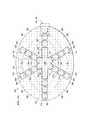
ここで図1A−図1Dを参照すると、開腔、減圧システム100および治療装置の例示的実施形態が示されている。開腔、減圧システム100および治療装置102は、患者の組織部位104を治療するためのものである。組織部位104は、骨組織、脂肪組織、筋組織、皮膚組織、組織、結合組織、軟骨、腱、靭帯または任意の他の組織を含むあらゆる人、動物または他の有機体の身体組織とすることができる。この例示する実施形態では、組織部位104は体腔、特に腹腔の組織を含み、腹腔に隣接する腹腔内容物または組織を含む。組織部位104の治療は、流体、例えば腹水の除去、腹腔の保護、または減圧治療を含むことができる。他に記載がない限り、本書で用いられるように、「または」は相互排他性を要求するものではない。 Referring now to FIGS. 1A-1D, an exemplary embodiment of an open space,
図示するように、治療装置102は組織部位104を治療するために患者の腹腔内に配置される。治療装置102は、腹腔内容物に支持される複数のカプセル型脚状部材106を含み、腹腔内容物は複数の脚状部材106が設けられる面を構成する。複数のカプセル型脚状部材106の1以上は、第1の結腸傍溝108内またはそれに隣接して設けることができ、複数のカプセル型脚状部材106の1以上は、第2の結腸傍溝110内またはそれに隣接して設けることができる。複数のカプセル型脚状部材106は中央連結部材112に連結され、複数のカプセル型脚状部材106と中央連結部材112との間で流体連通する。複数のカプセル型脚状部材106および/または中央連結部材112には、腹腔の流体の通過を可能にする開口部114、116、118、120を形成することができる。開口部114、116、118、120は任意の形状、例えば円形の穴、長方形の開口部、多角形などを取ることができるが、この例示する実施形態では細長い孔または線形の切り込みが示されている。1以上の開口部114、116、118、120は、代替実施形態では省略されるかもしれない。 As shown, the
マニホルド122、またはマニホルドパッドは治療装置102に減圧を分配する。シール部材124は、体腔開口部126上で空気の密閉をもたらす。1以上の皮膚閉鎖装置を患者の表皮134に配置することができる。減圧は、減圧伝達導管130に連結される減圧接続部128を通してマニホルド122に伝達される。減圧源132は、減圧伝達導管130に減圧を伝達する。 The manifold 122, or manifold pad, distributes the reduced pressure to the
減圧は組織部位104に適用され、組織部位104から腹水、浸出物または他の流体の除去を促進するのに役立つ。一部の実施例では、減圧は組織の成長を刺激するのに適用することができる。一部の実施例では、流体の除去のみが望まれるかもしれない。組織部位104の創傷の場合には、肉芽粗織の成長、滲出液の除去、または細菌の除去が創傷の治癒を促進するのに役立つであろう。創傷のないまたは良好な組織の場合には、組織の成長を促進する一部の実施例で減圧を用いることができ、これを摘出し、別の組織部位に移植することができる。本書で用いられるように、「減圧」とは一般に治療を受けている組織部位の周囲圧力以下の圧力のことをいう。多くの場合、この減圧は患者がいる位置の大気圧以下となるであろう。または、減圧は組織部位における静水圧以下でもよい。減圧は初めに、マニホルド122、減圧導管130、および隣接する組織部位104への流体流を生成することができる。組織部位104の周りの流体圧が所要の減圧に近づくと、流れが和らぎ、減圧を維持することができる。特に記載がなければ、本書で記載される圧力の値はゲージ圧である。 The reduced pressure is applied to the
マニホルド122は、中央連結部材112と隣接している。マニホルド122は、多くの形態を取ることができる。本書で用いられるように用語「マニホルド(manifold)」とは、一般に組織部位104に減圧を適用し、流体を送り、あるいはそこから流体を除去するのを支援するよう提供される物質または構造のことをいう。マニホルド122は一般に、中央連結部材112を介してマニホルド122周囲の組織部位104に提供され、そこから除去される流体を分配する複数の流路または経路を含む。例示する一実施形態では、流路または経路が相互に連結され、組織部位104に提供され、またはそこから除去される流体の分配を改善する。マニホルド122は、組織部位に接触して配置することができ、かつ組織部位に減圧を分配することができる生体適合性材料でもよい。マニホルド122の例としては、限定されないが、流路、連続気泡発泡体などの細胞状発泡体、多孔質組織収集体、液体、ゲルおよび流路を含むまたは流路を含むよう保持する発泡体を形成するよう配列された構造要素を有するデバイスを含むことができる。マニホルド122は多孔性とすることができ、特定の生物学的用途に適した発泡体、ガーゼ、フェルト状マット、または任意の他の材料から作成することができる。一実施形態では、マニホルド122は多孔性発泡体であり、流路として機能する複数の連続気泡または気孔を含む。多孔性発泡体は、テキサス州サンアントニオのKinetic Concepts社により製造されたGranuFoam(登録商標)材料などのポリウレタン、連続気泡、網状発泡体とすることができる。他の実施形態は、「独立気泡(closed cells)」を含むかもしれない。マニホルドのこれらの独立気泡の一部は複数の気泡を含んでよく、この大多数は隣接する気泡に流体的に接続されない。独立気泡は、マニホルド122に選択的に設けられ、マニホルド122の周囲面を通る流体の透過を防止する。一部の状況では、マニホルド122は組織部位104へ薬剤、抗菌物質、成長因子、および様々な溶液などの流体を分配するのに用いることもできる。マニホルド122の中に、あるいはその上に、吸収性材料、ウィッキング材料、疎水性材料、および親水性材料などの他の層を含むことができる。 The manifold 122 is adjacent to the central connecting
シール部材124は体腔開口部126上に設けられ、開腔、減圧システム100が組織部位104で減圧を保持するのに適当な空気の密閉をもたらす。シール部材124は、中央連結部材112にマニホルド122を固定するのに用いられるカバーでよい。シール部材124は不浸透性または半浸透性でよい。シール部材124は、体腔開口部126上にシール部材124を貼り付けた後、組織部位104の減圧を維持することができる。シール部材124は、シリコンベースの化合物、アクリル樹脂、ヒドロゲルもしくはヒドロゲル形成材料、または組織部位104に減圧を適用するのに要求される不浸透特性もしくは透過特性を含む任意の他の生体適合材料で形成された弾力性のあるオーバードレープもしくはフィルムでよい。 A
シール部材124はさらに、患者の表皮134にシール部材124を固定する接着手段131を含むことができる。接着手段131は、多くの形態を取ることができる。例えば、接着層136は、シール部材124の周囲に沿って、またはシール部材124の任意の一部に沿って設けることができ、直接または間接的に患者の表皮134に空気の密閉をもたらす。接着層136は、シール部材124に予め塗布されてもよく、適用時に除去される、取り外し可能な裏当または部材(図示せず)で覆われる。 The
減圧接続部128は、一実施例として、端子またはコネクタ138でよく、これはマニホルド122から減圧伝達導管130への、およびその逆への流路を可能にする。例えば、マニホルド122と治療装置102を用いて組織部位104から収集された流体は、コネクタ138を介して減圧伝達導管130に入ることができる。別の実施形態では、開腔、減圧システム100はコネクタ138を省略することができ、減圧伝達導管130はシール部材124とマニホルド122内へ直接挿入することができる。減圧伝達導管130は、医療用導管もしくはチューブ、または減圧と流体を輸送するための他の手段とすることができる。減圧伝達導管130は、容易に減圧を伝達し、流体を除去するための複数の内腔部材とすることができる。一実施形態では、減圧伝達導管130が2つの内腔を持つ導管であり、減圧と液体輸送のための1つの内腔と、圧力センサに圧力を伝達するための1つの内腔とを有する。 The
減圧源132は減圧を生成し、減圧伝達導管130に提供する。減圧源132は広範囲の減圧を生成し、または提供することができる。一実施形態では、この範囲が−50〜−300mmHgの範囲を含むことができ、別の実施形態では、この範囲が−100mmHg〜−200mmHgの範囲を含むことができる。例示する一実施形態では、減圧源132が−100mmHg、−125mmHg、および−150mmHgの予め設定された選別器を含む。減圧源132は、閉鎖警報器、漏電警報器またはバッテリ下限警報器などの多くの警報器を含んでもよい。減圧源132は、携帯型減圧源、壁用減圧源、または腹腔用の他の装置とすることができる。減圧源132は、定圧、可変圧力、間欠圧力、または連続圧力を選択的に伝達することができる。減圧伝達導管130を介して腔から除去された流体は、事実上1日当たり5L以上となる場合がある。 The reduced
多くの別の装置、例えば装置140を減圧伝達導管130の内側部分142に追加することができる。例えば、装置140は、流体リザーバ、もしくは缶状回収部材、圧力フィードバック装置、容量検出システム、血液検出システム、感染検出システム、フィルタ、フィルタ付き端子、フロー監視システム、温度監視システムなどであるかもしれない。複数の装置140を含んでもよい。これらの装置の幾つか、例えば流体回収部材は、減圧源132と一体に形成することができる。例えば、減圧源132上の減圧端子144は、1以上のフィルタを含むフィルター部材(図示せず)を具えることができ、液体が減圧源132の内部空間に入るのを防止する疎水性フィルタを含むことができる。 Many other devices, such as
ここで図1C、図1Dおよび図2を参照すると、治療装置102は非接着性ドレープ148を含むことができる。非接着性ドレープ148は、非接着性ドレープ148への組織接着を防止する非接着性材料で形成することができる。一実施形態では、非接着性ドレープ148が通気性のあるポリウレタンフイルムで形成される。非接着性ドレープ148は、複数の開口部、穴またはせん孔150を含むことができる。開口部は、円形の開口部、長方形の開口部、多角形の開口部などの様々な形状を取ることができるが、図2に示すように、細長い孔または線形の切れ目でもよい。装置102の特定の用途、所要の流量および/または圧力伝達、または他のシステムパラメータに依存して、開口部は異なるサイズに設定することができる。 Referring now to FIGS. 1C, 1D and 2, the
治療装置102は、複数のカプセル型脚状部材106が連結される中央連結部材112を含む。中央連結部材112は、第1の連結カプセル化部材186と第2の連結カプセル化部材192とでカプセル化されるマニホルド部材154を含む。しかしながら、中央連結部材の一部は脚状連結領域152で流体的に連結することができ、中央連結部材112と複数のカプセル型脚状部材106との間の流体連通を可能にする。第1と第2の連結カプセル化部材は一体構造の材料、または図示するように、1以上のシート材料で規定することができる。 The
中央連結部材112は、上記で論じたように、マニホルド122と流体的に連通することができる。一態様では、開口部118が、上記で論じた開口部と同様に、流体連通を可能にすることができる。さらに、または代わりに、第1の連結カプセル化部材の一部または複数の部分はマニホルド112に晒すことができる。 The
また図1A−図1Dを参照すると、複数のカプセル型脚状部材106の各々は脚状マニホルド部材160を含むことができ、これは脚状モジュール156および/もしくは中央連結部材112、または個々のマニホルドの構成要素の間を走るたった1つのマニホルド部材である。脚状マニホルド部材160は、カプセル型脚状部材106の各々の内部162に配置される。各脚状マニホルド部材160は、第1の面164と、第2の内向き(患者に対して)面166とを有している。 Referring also to FIGS. 1A-1D, each of the plurality of capsule-
一実施形態では、複数の脚状マニホルド部材160の1以上が異なる材質または構造を有することができる。例えば、異なる流速が異なるカプセル型脚状部材106に要求される場合がある。一態様では、異なるマニホルド材料またはマニホルド特性、異なるマニホルドサイズ、マニホルド圧縮、流れを制限する材料構造、および/またはバルブが、カプセル型脚状部材および/または中央連結部材を通る異なる流速の流体を提供することができる。 In one embodiment, one or more of the plurality of legged
一態様では、第1の脚状カプセル化部材168は、開口部114を形成することができ、脚状マニホルド部材160の第1の面164に配置される。第2の脚状カプセル化部材170は、開口部116を含むことができ、脚状マニホルド部材160の第2の内向き面166に配置される。第2の脚状カプセル化部材170は、第2の脚状カプセル型部材170は非接着性ドレープ148の一部である。一実施形態では、カプセル型脚状部材106は、例えばドレープ148を介して互いに結合することができる。代わりに、脚状部材は、中央連結部材112に隣接するその近位端を除いて互いに独立して動作することができる。例えば、脚状部材は互いに接続する必要はない。別の実施形態では、脚状部材に接続する材料の一部、例えば、隣接する脚状部材106間の非接着性ドレープ148は、拡張可能であり(例えば、伸縮性、柔軟性、変形性、および/または弾性の材料)、互いに個々の脚状部材106の動作を可能にする。 In one aspect, the first leg-shaped
図1Bの縦断面図に矢印172で示すように、流体は脚状モジュール156から中央連結部材112の方へ流れることができる。矢印174で示すように、流体は開口部114および116に入ることができ、脚状マニホルド部材160の中に流れ、次いで矢印172で表わされるように中央連結部材112の方へ流れることができる。 Fluid can flow from the
平面図では、カプセル型脚状部材106は伸長形状、矩形、楕円など、多くの異なる形状を取ることができる。一態様では、カプセル型脚状部材106が脚状モジュール156を含むことができる。隣接する脚状モジュール156は互いに流体的に連結して、それらの間に操作ゾーン158を有する。一態様では、操作ゾーンが弱体化または穿孔された領域を含み、装置のサイズ設定を容易にする。例えば、臨床医は装置のサイズを設定するために脚状モジュールを切り取ることができる。部分的に切り取る脚状モジュールを引っ張ることにより、次の操作ゾーンでマニホルドを引き剥がすことができる。一態様では、操作ゾーン158の凹部形状が、さらに脚状モジュールを思い掛けず除去してしまうのを防止することができる。さらに、または代わりに、脚状モジュールの外側部分を装置に固定することができ、不要なマニホルドの除去を防止する。 In plan view, the capsule-shaped
カプセル型脚状部材106は様々な寸法を有してもよい。カプセル型脚状部材106の長寸、例えば、縦寸もしくは長手寸がL1で、幅がW1である場合、アスペクト比はL1/W1で与えられる。アスペクト比は、8.0、7.0、6.0、5.0、4.0、3.0、2.0またはその間の任意の数値とすることができる。さらに、その他のアスペクト比が可能である。通常、カプセル型脚状部材の幅W1は、中央連結部材112の幅W2より大きく、すなわち、W2>W1である。例えば、例示する一実施形態では、カプセル型脚状部材106は約270mmの長さであり、60mmの幅(W1)であり、10mmの厚さであり、中央連結部材は約130mm(W2)の第1の幅(W1)に平行な幅を有する。したがって、その例示する実施例では、カプセル型脚状部材106のアスペクト比は約(270/60)または4.5である。この同一の例示する実施形態では、操作ゾーン158は約10mmの幅を有している。The capsule-
図1Cを参照すると、カプセル型脚状部材106の一部の側断面図が示されている。前述のように、脚状マニホルド部材160の第1の面164が第1のカプセル化部材168で覆われ、脚状マニホルド部材160の第2の内向き面166が第2の脚状カプセル化部材170により覆われており、これは本実施例では非接着性ドレープ148の一部である。したがって、この実施例では、開口部116が非接着性ドレープ148の複数の開口部150の一部でよい。この実施例では、脚状マニホルド部材160の周辺端部176はさらに第1の脚状カプセル化部材168の一部で覆われる。周端部176は、第1の側端部177と第2の側端部179とを含む。第1の脚状カプセル化部材168は第1の面164と周端部176を覆い、非接着性ドレープ148の第1の面178上に延在し、外延部180を形成する。外延部180は溶接部182で第2の脚状カプセル化部材170に連結している。第1の脚状カプセル化部材168は、しかしながら、溶接(例えば超音波溶接または高周波溶接)、結合、接着剤、セメント剤等を含む任意の既知技術を用いて第2の脚状カプセル化部材170に連結してよい。 Referring to FIG. 1C, a cross-sectional side view of a portion of the capsule-
図1Dおよび図2を再度参照すると、中央連結部材112は、第1の連結カプセル化部材186にカプセル化される連結マニホルド部材154を含み、これは開口部118を有する。第1の連結カプセル化部材186は、連結マニホルド部材154の第1の面188に配置される。第2の連結カプセル化部材192は、連結マニホルド部材154の第2の内向き面190に配置される。第2の連結カプセル化部材192には、開口部120が形成される。第1の連結カプセル化部材186は、図2に示すように辺縁部または端部194を有する。同様に、第2の連結カプセル化部材192は周端部194に並ぶ辺縁部または端部(明示的に示されていない)を有する。図1Dの矢印196で示すように、複数のカプセル型脚状部材106内の流体が連結マニホルド部材154に流れるのを可能にするために、脚状連結領域152を除いて、第1の連結カプセル化部材186の周端部194は第2の連結カプセル化部材192の周端部に連結される。流体は、矢印198で示すように開口部120を通って流れることにより連結マニホルド部材154に直接入ることもできる。マニホルド122は第1の連結カプセル化部材186に隣接して配置され、減圧がマニホルド122に適用されるとき、この減圧が矢印200で示すように連結マニホルド部材154から開口部118を通ってマニホルド122に流体を流れさせる。流体は減圧接続部128の方向に流れ続け、これを通って流体が減圧伝達導管130へ除去される。 Referring back to FIGS. 1D and 2, the
図1A−図1Dおよび図2を参照すると、実施中、例示する開腔、減圧システム100は、図3Aに関して以下でさらに説明するように、治療装置102を最初にサイズ設定することにより用いることができる。非接着性ドレープ148は複数のカプセル型脚状部材106と共に、体腔開口部126を介して腹腔内に配置され、腹腔内容物に対して分配される。これは、第1の結腸傍溝108、第2の結腸傍溝110の中もしくはこれに隣接して、または肝臓の後ろなどに少なくとも1つのカプセル型脚状部材106を設けるステップを含む。一旦治療装置102が分配された後、マニホルド122が第1の連結カプセル化部材186の第1の面184に隣接して設けられる。次いで、シール部材124が体腔開口部126上に適用され、体腔開口部126を越える空気の密閉をもたらす。 With reference to FIGS. 1A-1D and 2, in practice, the illustrated open-cavity,
シール部材124に加えて、体腔開口部126はさらに、機械的閉鎖手段、例えばステープルを用いて、または減圧閉鎖システムを用いて、閉じるか補強することができる。シール部材124は多くの方法で適用されるが、例示する一実施例によれば、シール部材124の接着層136にある取り外し可能な裏当部材が除去され、次いでシール部材124が体腔開口部126周囲の患者の表皮134に対して設けられる。次いで、端子138などの減圧接続部128がシール部材124に取り付けられ、これにより減圧は、接続部128により、シール部材124を通って、マニホルド122に伝達することができる。減圧伝達導管130は、減圧接続部128と減圧源132の減圧端子144に流体的に連結される。 In addition to the
減圧源132が起動され、これにより減圧伝達導管130に減圧を提供し、これは減圧接続部128とマニホルド122に減圧を伝達する。マニホルド122は減圧を分配し、開口部118を介して連結マニホルド部材154から流体を抜き取る。連結マニホルド部材154は腹腔から開口部120を介して流体を抜き取り、矢印196で示すように複数のカプセル型脚状部材106から流体を引き寄せる。腹腔からの流体は、第1の脚状カプセル化部材168の開口部114と、第2のカプセル化部材170の開口部116とを通って複数のカプセル型脚状部材106に流れ、次いで連結マニホルド部材154の方へ矢印172で示すように脚を通って流れる。次いで、流体はマニホルド122、減圧接続部128、減圧伝達導管130を通って流れる。 The reduced
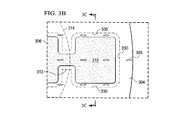
ここで図3A−図3Cを参照すると、開腔、減圧治療装置302の別の例示する実施形態が示されている。開腔、減圧治療装置302は、図1A−図1Dの治療装置102とほぼ同じである。開腔、減圧治療装置302は、非接着性ドレープ304と、複数のカプセル型脚状部材306と、中央連結部材308とを有する。この特定の例示する実施形態では、非接着性ドレープ304が略楕円または弓の形状で形成される。非接着性ドレープ304には複数の開口部305が形成される。非接着性ドレープ304は、第2の脚状カプセル化部材(図1Bの類似する第2の脚状カプセル化部材170を参照)と、第2の連結カプセル化部材とを形成する(図1Dの類似する192を参照)。そのため、複数の開口部305は、第2の内向き面で複数のカプセル型脚状部材306と中央連結部材308の流路として機能する。非接着性ドレープ304は、複数のカプセル型脚状部材306と中央連結部材308の第1の面に用いることもできる。 Referring now to FIGS. 3A-3C, another exemplary embodiment of an open space, reduced
カプセル型脚状部材306の各々には、複数の脚状モジュール310の間に操作ゾーン312を有する複数の脚状モジュール310を形成することができる。図1A−1Dの操作ゾーン158のように、操作ゾーン312は、体腔内の複数のカプセル型脚状部材306の動作を容易にし、開腔、減圧治療装置302が特定用途にサイズ設定される場合に複数のカプセル型脚状部材306を切り取るためのより簡単な位置を提供するものである。この点に関して、目印314は、非接着性ドレープ304に加えることができ、腔内で異なるサイズで利用するため、医療サービス提供者が非接着性ドレープ304を切り取る位置を知るのに役立つ。目印314は、好ましくは操作ゾーン312を通って走る切れ目、または目盛りを含むことができる。操作ゾーン312は、開腔、減圧治療装置302を切り取るための使い勝手の良い、簡単な位置を提供する。 A plurality of leg-shaped
図3Cを参照すると、カプセル型脚状部材306の一部の側断面図が示されている。複数のカプセル型脚状部材306には、第1の面320と第2の内向き(患者に対向する)面322とを有する脚状マニホルド部材318が形成される。第1の脚状カプセル化部材324は、脚状マニホルド部材318の第1の面320を覆い、脚状マニホルド部材318の側方区域または側端部326を覆う。脚状マニホルド部材318の第2の内向き面322は、第2の脚状カプセル化部材328により覆われており、これは本実施例では非接着性ドレープ304の一部である。第1の脚状カプセル化部材324は、この分野で知られる任意の手段、溶接(例えば超音波または高周波)、結合、接着剤、セメント剤などで第2の脚状カプセル化部材328に連結される。この例示する実施形態では、第1の脚状カプセル化部材324と第2の脚状カプセル化部材328が溶接部330で連結される。図3Bを参照すると、複数の脚状モジュール310の周囲に沿って溶接部330が示されている。 Referring to FIG. 3C, a side cross-sectional view of a portion of the capsule-
また図3Aを参照すると、中央連結部材308が図2の中央連結部材112と同様に形成される。中央連結部材308の第1の連結カプセル化部材334と第2の連結カプセル化部材は、溶接部333または別の連結技術を用いて周端部332に沿って連結される。複数のカプセル型脚状部材306から中央連結部材308に流体が流れる通路を提供するために、周端部332は密封されないが、カプセル型脚状部材306の各々に隣接する。 3A, the central connecting
開腔、減圧治療装置302を構築する1つの例示的なアプローチによれば、既に複数の開口部305が形成され、目印314を有する非接着性ドレープ304が提供される。脚状マニホルド部材318は、非接着性ドレープ304に隣接して配置される。中央連結マニホルド308は、脚状マニホルド部材318に隣接して配置されるか、または脚状マニホルド部材318と一体に形成することができる。第1の連結カプセル化部材334は中央連結部材308に設けられ、第1の脚状カプセル化部材324は脚状マニホルド部材318上に設けられる。第1の連結カプセル化部材334と第1の脚状カプセル化部材324は、一体型のシートで形成することができる。次に、溶接部330および333が適用される。 According to one exemplary approach to constructing an open, reduced
開腔、減圧治療装置を製造するための代替実施形態では、開口部を含む第1の非接着性ドレープ304を提供することができ、脚状マニホルド部材318と中央連結マニホルド308が第1の非接着性ドレープ304上に配置される。開口部を有する第2の非接着性ドレープは第1の非接着性ドレープ304、脚状マニホルド部材318、および中央連結マニホルド308上に設けられる。次に、溶接部330などの複数の溶接部(例えば、熱もしくは高周波または別の連結技術が用いられる)が作られる。第1の非接着性ドレープ304と第2の非接着性ドレープは、組み立てる前または後に切り取ってサイズ設定することができる。2つのドレープ、第1の非接着性ドレープ304と第2の非接着性ドレープを用いることにより、減圧の良好な分配を提供することができ、製造工程を容易にすることができる。 In an alternative embodiment for manufacturing an open space, reduced pressure treatment device, a first
開口部は、組み立てる前または後に形成することができる。第1の非接着性ドレープ304と第2の非接着性ドレープの周囲を溶接することができる。ドレープ間の他の点を溶接して単一ユニットを形成することができる。別の代替実施形態では、ドレープは最初に開口部なしに設けて溶接することができ、次いで開口部がドレープに加えられ、これにより開口部が整列する。開口部は切断および密封を同時に行なう電気的な部材を用いて形成することもでき、2つのドレープを通って配列した「ボタンホール(button hole)」を形成する。 The opening can be formed before or after assembly. The perimeter of the first
ここで図4を参照すると、開腔、減圧治療装置402の別の例示的な実施形態が示されている。開腔、減圧治療装置402は図2に示す治療装置102と類似しており、類似した部分を示すために、参照符号が300の差で付けられた。開腔、減圧治療装置402は初めに、流体輸送サブシステム445が含まれる点で異なる。複数のカプセル型脚状部材406は脚状モジュールなく示されており、開口部は円形に示されている。前に記載したように、複数のカプセル型脚状部材406は脚状モジュールと共に、または脚状モジュールなしに形成することができる。流体輸送サブシステム445は、薬剤または洗浄流体などの様々な流体の腔への輸送を可能にするものである。次いで、輸送された流体は開腔、減圧治療装置402で除去することができる。流体輸送サブシステム445は中央端子447を含み、これは中央端子447の外部の位置から流体を輸送する導管(図示せず)に接続するための中央連結部材412上またはその中に設けることができる。複数の流体輸送導管449が中央端子447に流体的に連結される。複数の流体輸送導管449は、非接着性ドレープ448上のどんな場所にも配置することができるが、この例示する実施形態では、複数のカプセル型脚状部材406の中に配置される。複数の流体輸送導管449は遠位端451で開いており、ここを通る流体の輸送を可能にする。複数の流体輸送導管449の遠位端451を通る流体の流れは、矢印453で示されている。 Referring now to FIG. 4, another exemplary embodiment of an open space, reduced
使用の際には、治療装置102および302と同様に開腔、減圧治療装置402を用いることができるが、様々な時間にまたは均一で連続的に、流体輸送サブシステム445を通る流体を輸送することが望ましいであろう。例えば、洗浄流体で腹腔を洗い流すか、または周期的な投与量の薬剤を輸送することが望ましいであろう。 In use, an open-cavity, reduced
ここで開腔、減圧治療装置(例えば、腔、減圧治療装置102、302、402)またはシステムを用いる別の例示的な実施形態を示す。システムは、腹壁開口部の一時的なブリッジングに特に適しており、一次閉鎖は容易に可能でなく、および/または繰り返し腹部への進入が必要である。本書で記載される例示的なシステムは、限定されないが腹部コンパートメント症候群を含む、開腹部創傷、露出した内臓に用いることができる。システムを適用する前に、一般に止血が得なければならない。 Here, another exemplary embodiment using an open space, reduced pressure treatment device (eg, cavity, reduced
開腔、減圧治療システムを配置する際、減圧治療装置は露出した内臓を全て覆うことが好ましく、内臓を腹壁との接触から完全に分離することが好ましい。例えば、ドレープ148などの減圧治療装置の最下面は、サイズ設定して、適用範囲を覆うことができるよう形成することができる。減圧治療装置は、網または露出した内部臓器上に設けることができ、慎重に腹壁と内部臓器との間に差し込むことができる。そうすることで、医療サービス提供者は減圧治療装置を用いて内部臓器から腹壁を完全に分離することができる。 When placing an open space, reduced pressure treatment system, the reduced pressure treatment device preferably covers all exposed viscera and preferably completely separates the viscera from contact with the abdominal wall. For example, the bottom surface of a reduced pressure treatment device such as
システムの配置の準備をするため、総ての鋭い端もしくは骨片が創傷領域から除去されるか、または覆われる。腹部創が洗浄され、周辺の創領域が洗浄される。表皮の周辺の創組織は一般にさらに適用する前に乾燥される。 All sharp edges or bone fragments are removed or covered from the wound area in preparation for system deployment. The abdominal wound is cleaned and the surrounding wound area is cleaned. The wound tissue around the epidermis is generally dried before further application.
次いで、減圧治療装置は適切なサイズを決定し、切り取ることでサイズ設定される。減圧治療装置は、初めに滅菌野に広げられる。減圧治療装置の何れ面も網または内臓上に設けることができる。減圧治療装置は、開腹腔上にそっと設けられる。特定用途のため減圧治療装置の方向が決定される。減圧治療装置はチューブ、ドレインまたは鎌状間膜の周りに設けられる場合、減圧装置が複数のカプセル型脚状部材の間でのみ切り取られる。減圧治療装置は、切り取る前に適切な方向に設けられる。 The reduced pressure treatment device is then sized by determining and cutting the appropriate size. The reduced pressure therapy device is first expanded into the sterile field. Either side of the reduced pressure treatment device can be provided on the net or internal organs. The reduced pressure treatment device is gently provided on the open abdominal cavity. The orientation of the reduced pressure therapy device is determined for a specific application. When a reduced pressure treatment device is provided around the tube, drain or sickle-like mesenchyme, the reduced pressure device is cut only between the plurality of capsule-type leg members. The decompression therapy device is installed in the appropriate direction before cutting.
次いで、減圧治療装置は折り畳まれてサイズ設定され、そのまま使用するか、または切り取ることができる。医療サービス提供者は端部に減圧治療装置を保持し、僅かに減圧治療装置を持ち上げる。減圧治療装置はゆっくり一方の手で結腸傍溝内へ降ろされ、他方の手は減圧治療装置を下へそっと均一に動かすのに用いられる。医療サービス提供者は減圧治療装置の総ての余剰部分をそれ自体へ折り畳む。医療サービス提供者は、続けて腹部の区画全体に渡って腹壁と内部臓器との間に減圧治療装置を設ける。医療サービス提供者は、全ての内臓の全適用範囲に提供することが好ましい。次いで、必要とする減圧治療装置を切り取って創傷の外側にサイズ設定することができる。 The reduced pressure therapy device can then be folded and sized and used as is or cut out. The medical service provider holds the reduced pressure treatment device at the end and lifts the reduced pressure treatment device slightly. The vacuum treatment device is slowly lowered into the paracolonial groove with one hand and the other hand is used to move the vacuum treatment device gently and evenly down. The medical service provider folds all excess parts of the reduced pressure treatment device into itself. The medical service provider then installs a reduced pressure treatment device between the abdominal wall and the internal organ over the entire abdominal compartment. The medical service provider preferably provides the entire coverage of all internal organs. The required reduced pressure treatment device can then be cut and sized outside the wound.
装置をサイズ設定するために、減圧治療装置は、無菌ばさみを用いて、大きなマニホルドスクエアまたは脚状モジュールの1つの中央を切断することができる。この例示する実施形態では、切断が操作ゾーンではなく、脚状モジュールに渡ってなされる。次いで、医療サービス提供者は片手で発泡体スクエアの残り半分または脚状モジュールと、カプセル化部材に渡って隣接する内側の操作ゾーンとを摘み、マニホルド材料を引っ張る。脚状モジュールのマニホルド材料と操作ゾーンは、次のスクエアもしくは脚状モジュールで分離される。これは、減圧治療装置の端部が別の露出したマニホルド端部を覆うのを保証するものである。マニホルド材料、例えば発泡体は、臓器と接触しないことが好ましい。 In order to size the device, the reduced pressure treatment device can cut one center of a large manifold square or leg module using sterile scissors. In this exemplary embodiment, the cut is made across the leg module rather than the operating zone. The health care provider then picks the remaining half of the foam square or leg-shaped module and the adjacent inner operating zone across the encapsulating member and pulls the manifold material with one hand. The leg module manifold material and the operating zone are separated by the next square or leg module. This ensures that the end of the reduced pressure treatment device covers another exposed manifold end. The manifold material, eg foam, is preferably not in contact with the organ.
次に、中央連結部材の頂部に設けられるマニホルドが準備される。この実施形態では、マニホルドは穿孔を有する被穿孔発泡体マニホルドとすることができ、所望サイズにマニホルドを引きちぎるのに役立つ。マニホルドは、まだ創傷端部に接している間に減圧治療装置上で直接適合することが好ましい。マニホルドは、無傷の皮膚に接触すべきではない。2以上のマニホルドは、幾つかの実施例で用いることができる。次いで、サイズ設定されたマニホルドが減圧治療装置上の創腔にそっと設けられる。医療サービス提供者は、マニホルドが腹部切開または創傷の高さより下に進むを避けるように注意することが好ましい。 Next, a manifold provided on the top of the central connecting member is prepared. In this embodiment, the manifold can be a perforated foam manifold with perforations, which helps to tear the manifold to the desired size. The manifold is preferably fitted directly on the reduced pressure treatment device while still in contact with the wound end. The manifold should not contact intact skin. Two or more manifolds can be used in some embodiments. A sized manifold is then gently placed in the wound space on the reduced pressure treatment device. The health care provider preferably takes care to avoid the manifold going below the abdominal incision or wound height.
次いで、ドレープまたはオーバードレープが適用される。ドレープを適用するために、裏当がドレープの一方の面の接着層から除去され、ドレープが貼られる。ドレープは、マニホルドと無傷の表皮の一部を覆う。ドレープが少なくとも無傷の創傷周辺組織の8−10センチメートルの辺縁部を覆うことが好ましい。さらにドレープ材料が加えられて総ての困難な領域を密封することができる。 A drape or overdrape is then applied. To apply the drape, the backing is removed from the adhesive layer on one side of the drape and the drape is applied. The drape covers the manifold and part of the intact epidermis. Preferably, the drape covers at least the 8-10 centimeter margin of intact peri-wound tissue. In addition, drape material can be added to seal all difficult areas.
次いで、減圧接続部または接続パッドが加えられる。医療サービス提供者は、適用部位を選択する。この部位は流量を最適化し、管の位置決めを容易にするよう選択される。医療サービス提供者はドレープを摘み、ドレープを通る2.5cmの穴(細長い穴でないことが好ましい)を切り取る。中央盤と周囲の外側の接着裾を有する接続パッドが貼られる。接続パッドは、接着剤を晒すために接続パッドの内向き面の裏当層を除去することにより貼られる。中央盤の接続パッドの開口部は、ドレープの穴に直接設けられる。中央盤と外側の裾に圧力がそっと掛けられて接続パッドの完全な接着を確保する。次いで、1以上の安定化層が裾の第1の面から除去される。ここでシステムは、減圧を適用する準備が整う。 A reduced pressure connection or connection pad is then added. The medical service provider selects an application site. This site is selected to optimize flow rate and facilitate tube positioning. The health care provider picks the drape and cuts a 2.5 cm hole (preferably not an elongated hole) through the drape. A connection pad having a central board and an outer peripheral adhesive hem is applied. The connection pad is applied by removing the backing layer on the inward side of the connection pad to expose the adhesive. The opening of the connection pad of the center board is provided directly in the hole of the drape. Pressure is gently applied to the center board and the outer hem to ensure complete bonding of the connection pads. The one or more stabilization layers are then removed from the first surface of the skirt. The system is now ready to apply a vacuum.
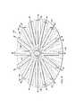
図5に示される別の例示する実施形態によれば、開腔、減圧治療装置502が中央流体ハブ512と複数の伸長部材506を含む。中央流体ハブ512は、頂面513と底面を有する。中央流体ハブ512は、頂面513の一部を規定する発泡体マニホルド554と、底面の少なくとも一部を規定する実質的に流体を浸透しない壁とを含む。流体を浸透しない壁は、複数の開口部518を含む。複数の伸長部材506は、近位端515、遠位端517、および頂部519と底面を有する。伸長部材506は、実質的に流体を浸透しない壁に囲まれた発泡体を含む。複数の伸長部材506の近位端515は、中央流体ハブ512と流体連通する。伸長部材506は、伸長部材506の底面の少なくとも一部に沿って流体を浸透しない壁を通って延在する開口部514を含む。 According to another exemplary embodiment shown in FIG. 5, an open lumen, reduced
複数の伸長部材506は、中央流体ハブ512から延在する第1の長さL1と、頂面に略平行で、第1の長さに垂直な第1の幅(W1)を有する。中央ハブは、第1と第2の伸長部材の間の一部の側端部の間に第2の幅(W2)を有する。第2の幅は、第1の幅より大きい(W2>W1)。複数の伸長部材506は、中央ハブ512に流体的に連結される。開腔、減圧治療装置502は、3.0〜10.0の範囲内で複数の伸長部材506のアスペクト比を有することができる。開腔、減圧治療装置502は、3.5より大きい複数の伸長部材506のアスペクト比を有することができる。開腔、減圧治療装置502は、複数の伸長部材506の間に延在する弾性材料585を含むこともできる。The plurality of
本発明とその利点が特定の例示的で非限定的な実施形態の内容で開示されたが、添付の請求項により規定されるように、本発明の範囲から逸脱することなく、様々な変更、代替、置換および修正を行うことができることを理解されたい。何れか1つの実施形態との関係で示された任意の特徴は、任意の他の実施形態にも適用可能であることを認識されるであろう。 While the invention and its advantages have been disclosed in the context of certain exemplary, non-limiting embodiments, various modifications, without departing from the scope of the invention, as defined by the appended claims, It should be understood that substitutions, substitutions and modifications can be made. It will be appreciated that any feature shown in relation to any one embodiment is applicable to any other embodiment.
Claims (18)
Translated fromJapanese複数のカプセル型脚状部材であって、各カプセル型脚状部材が内部を有し、当該内部に脚状マニホルド部材が配置され、前記複数のカプセル型脚状部材が前記カプセル型脚状部材の外部と内部との間の流体流を受け入れる開口部を含む、複数のカプセル型脚状部材と、
連結マニホルド部材を有する中央連結部材であって、前記複数の脚状マニホルド部材が前記連結マニホルド部材と流体連通する、中央連結部材とを具える治療装置と、
前記中央連結部材に隣接して配置するマニホルドと、
前記体腔上で空気の密閉を形成するよう機能するシール部材とを具えることを特徴とするシステム。In a system for treating a body cavity,
A plurality of capsule-type leg-shaped members, each capsule-type leg-shaped member having an inside, and a leg-shaped manifold member disposed therein, wherein the plurality of capsule-type leg-shaped members are arranged on the capsule-type leg-shaped member; A plurality of capsule-shaped leg members including openings for receiving fluid flow between the exterior and interior;
A central coupling member having a coupling manifold member, the treatment device comprising a central coupling member, wherein the plurality of leg-shaped manifold members are in fluid communication with the coupling manifold member;
A manifold disposed adjacent to the central connecting member;
And a sealing member that functions to form an air seal over the body cavity.
第1の脚状カプセル化部材と、
開口部が形成された第2の脚状カプセル化部材とを具え、
前記脚状マニホルド部材が第1の面、これに対向する第2の面、第1の側端部、および第2の側端部を有し、
前記第1の脚状カプセル化部材が前記脚状マニホルド部材の第1の面に隣接して配置され、前記第2の脚状カプセル化部材が前記脚状マニホルド部材の第2の面に隣接して配置され、前記第1の脚状カプセル化部材と前記第2の脚状カプセル化部材が前記脚状マニホルド部材の第1の側端部と第2の側端部に隣接して連結されることを特徴とするシステム。The system according to claim 1, wherein the plurality of capsule-type leg members are:
A first leg-like encapsulating member;
A second leg-shaped encapsulating member having an opening formed therein;
The leg-shaped manifold member has a first surface,a second surface opposite thereto , a first side end, and a second side end;
The first leg-shaped encapsulating member is disposed adjacent to the first surface of the leg-shaped manifold member, andthe second leg-shaped encapsulating member is adjacent tothe second surface ofthe leg-shaped manifold member. And the first leg-shaped encapsulating member and the second leg-shaped encapsulating member are connected adjacent to the first side end and the second side end of the leg-shaped manifold member. A system characterized by that.
開口部が形成され、周端部を有する第1の連結カプセル化部材と、
開口部が形成された第2の連結カプセル化部材とを具え、
前記第1の連結カプセル化部材の周端部が、少なくとも部分的に前記第2の連結カプセル化部材に連結されることを特徴とするシステム。The system of claim 1, wherein the central connecting member is
A first coupled encapsulating member having an opening and having a peripheral end;
A second connected encapsulation member having an opening formed therein,
A system wherein the peripheral end of the first coupled encapsulation member is at least partially coupled to the second coupled encapsulation member.
開口部が形成された第1の脚状カプセル化部材と、
開口部が形成された第2の脚状カプセル化部材とを具え、
前記脚状マニホルド部材が第1の面、これに対向する第2の面、第1の側端部、および第2の側端部を有し、
前記第1の脚状カプセル化部材が前記脚状マニホルド部材の第1の面に隣接して配置され、前記第2の脚状カプセル化部材が前記脚状マニホルド部材の第2の面に隣接して配置され、前記第1の脚状カプセル化部材と前記第2の脚状カプセル化部材が前記脚状マニホルド部材の第1の側端部と第2の側端部に隣接して連結され、
前記中央連結部材は、
開口部が形成され、周端部を有する第1の連結カプセル化部材と、
開口部が形成された第2の連結カプセル化部材とを具え、
前記第1の連結カプセル化部材の周端部が、少なくとも部分的に前記第2の連結カプセル化部材に連結されることを特徴とするシステム。The system according to claim 1, wherein each of the capsule leg members of the plurality of capsule leg members is:
A first leg-shaped encapsulating member having an opening formed therein;
A second leg-shaped encapsulating member having an opening formed therein;
The leg-shaped manifold member has a first surface,a second surface opposite thereto , a first side end, and a second side end;
The first leg-shaped encapsulating member is disposed adjacent to the first surface of the leg-shaped manifold member, andthe second leg-shaped encapsulating member is adjacent tothe second surface ofthe leg-shaped manifold member. The first leg-shaped encapsulating member and the second leg-shaped encapsulating member are connected adjacent to the first side end and the second side end of the leg-shaped manifold member;
The central connecting member is
A first coupled encapsulating member having an opening and having a peripheral end;
A second connected encapsulation member having an opening formed therein,
A system wherein the peripheral end of the first coupled encapsulation member is at least partially coupled to the second coupled encapsulation member.
内部を有する複数のカプセル型脚状部材であって、当該内部に脚状マニホルド部材が配置され、前記複数のカプセル型脚状部材には前記内部への流体流を受け入れるよう機能する開口部が形成される、複数のカプセル型脚状部材と、
連結マニホルド部材を有する中央連結部材であって、前記脚状マニホルド部材が前記連結マニホルド部材と流体連通する、中央連結部材とを具えることを特徴とする治療装置。A treatment device for treating a tissue site, the treatment device comprising:
A plurality of capsule-type leg members having an interior, wherein leg-like manifold members are disposed therein, and the plurality of capsule-type leg members are formed with openings that function to receive a fluid flow into the interior. A plurality of capsule-shaped leg-shaped members;
A treatment device comprising a central connection member having a connection manifold member, wherein the leg-shaped manifold member is in fluid communication with the connection manifold member.
第1の脚状カプセル化部材と、
開口部が形成された第2の脚状カプセル化部材とを具え、
前記脚状マニホルド部材が第1の面、これに対向する第2の面、第1の側端部、および第2の側端部を有し、
前記第1の脚状カプセル化部材が前記脚状マニホルド部材の第1の面に隣接して配置され、前記第2の脚状カプセル化部材が前記脚状マニホルド部材の第2の面に隣接して配置され、前記第1の脚状カプセル化部材と前記第2の脚状カプセル化部材が前記脚状マニホルド部材の第1の側端部と第2の側端部に隣接して連結されることを特徴とする治療装置。The treatment apparatus according to claim 6, wherein each of the capsule-type leg-shaped members of the plurality of capsule-type leg-shaped members includes:
A first leg-like encapsulating member;
A second leg-shaped encapsulating member having an opening formed therein;
The leg-shaped manifold member has a first surface,a second surface opposite thereto , a first side end, and a second side end;
The first leg-shaped encapsulating member is disposed adjacent to the first surface of the leg-shaped manifold member, andthe second leg-shaped encapsulating member is adjacent tothe second surface ofthe leg-shaped manifold member. And the first leg-shaped encapsulating member and the second leg-shaped encapsulating member are connected adjacent to the first side end and the second side end of the leg-shaped manifold member. A treatment device characterized by that.
開口部が形成され、周端部を有する第1の連結カプセル化部材と、
開口部が形成された第2の連結カプセル化部材とを具え、
前記第1の連結カプセル化部材の周端部が、少なくとも部分的に前記第2の連結カプセル化部材に連結されることを特徴とする治療装置。The treatment apparatus according to claim 6, wherein the central connecting member is
A first coupled encapsulating member having an opening and having a peripheral end;
A second connected encapsulation member having an opening formed therein,
A treatment apparatus, wherein a peripheral end portion of the first coupled encapsulation member is at least partially coupled to the second coupled encapsulation member.
開口部が形成された第1の脚状カプセル化部材と、
開口部が形成された第2の脚状カプセル化部材とを具え、
前記脚状マニホルド部材が第1の面、これに対向する第2の面、第1の側端部、および第2の側端部を有し、
前記第1の脚状カプセル化部材が前記脚状マニホルド部材の第1の面に隣接して配置され、前記第2の脚状カプセル化部材が前記脚状マニホルド部材の第2の面に隣接して配置され、前記第1の脚状カプセル化部材と前記第2の脚状カプセル化部材が前記脚状マニホルド部材の第1の側端部と第2の側端部に隣接して連結され、
前記中央連結部材は、
開口部が形成され、周端部を有する第1の連結カプセル化部材と、
開口部が形成された第2の連結カプセル化部材とを具え、
前記第1の連結カプセル化部材の周端部が、少なくとも部分的に前記第2の連結カプセル化部材に連結されることを特徴とする治療装置。The treatment apparatus according to claim 6, wherein each of the capsule-type leg-like members of the plurality of capsule-type leg-like members is:
A first leg-shaped encapsulating member having an opening formed therein;
A second leg-shaped encapsulating member having an opening formed therein;
The leg-shaped manifold member has a first surface,a second surface opposite thereto , a first side end, and a second side end;
The first leg-shaped encapsulating member is disposed adjacent to the first surface of the leg-shaped manifold member, andthe second leg-shaped encapsulating member is adjacent tothe second surface ofthe leg-shaped manifold member. The first leg-shaped encapsulating member and the second leg-shaped encapsulating member are connected adjacent to the first side end and the second side end of the leg-shaped manifold member;
The central connecting member is
A first coupled encapsulating member having an opening and having a peripheral end;
A second connected encapsulation member having an opening formed therein,
A treatment apparatus, wherein a peripheral end portion of the first coupled encapsulation member is at least partially coupled to the second coupled encapsulation member.
頂面と底面を有する中央流体ハブであって、当該中央流体ハブが前記頂面の少なくとも一部を規定する発泡体マニホルドと、前記底面の少なくとも一部を規定する実質的に流体を浸透しない壁とを含み、当該流体を浸透しない壁が複数の開口部を含む、中央流体ハブと、
近位端、遠位端、頂面、および底面を有する複数の伸長部材であって、当該伸長部材が前記実質的に流体を浸透しない壁で囲まれる発泡体を含み、前記複数の伸長部材の近位端が前記中央流体ハブと流体連通し、前記伸長部材が当該伸長部材の底面の少なくとも一部に沿って流体を浸透しない壁を通り延在する開口部を含む、複数の伸長部材とを具えることを特徴とする治療装置。A therapeutic device,
A central fluid hub having a top surface and a bottom surface,wherein the central fluid hub defines at least a portion of the top surface, and a substantially fluid impermeable wall defining at least a portion of the bottom surface. A central fluid hub, wherein the fluid impermeable wall includes a plurality of openings;
A plurality of elongate members having a proximal end, a distal end, a top surface, and a bottom surface, the elongate member including a foam surrounded by the substantially impermeable wall; A plurality of elongate members, wherein a proximal end is in fluid communication with the central fluid hub, and the elongate member includes an opening extending through a wall that does not penetrate fluid along at least a portion of the bottom surface of the elongate member; A treatment device characterized by comprising.
前記複数の伸長部材が前記中央流体ハブから延在する第1の長さL1と、前記伸長部材の頂面に略平行な第1の幅(W1)とを有し、
前記中央流体ハブが第1および第2の伸長部材の間の第2の幅(W2)を有し、
当該第2の幅が前記第1の幅より大きく(W2>W1)、
前記複数の伸長部材のアスペクト比(L1〜W1)が3.0〜10.0の範囲内であることを特徴とする治療装置。The treatment device according to claim 14, wherein
The plurality of elongated members have a first length L1 extending from the central fluid hub and a first width (W1 ) substantially parallel to the top surface of the elongated member;
The central fluid hub has a second width (W2 ) between the first and second elongated members;
The second width is greater than the first width (W2 > W1 ),
An aspect ratio (L1 to W1 ) of the plurality of elongated members is within a range of 3.0 to 10.0.
前記複数の伸長部材が前記中央流体ハブから延在する第1の長さL1と、前記伸長部材の頂面に略平行な第1の幅(W1)とを有し、
前記中央流体ハブが第1および第2の伸長部材の間の第2の幅(W2)を有し、
当該第2の幅が前記第1の幅より大きく(W2>W1)、
前記複数の伸長部材のアスペクト比が3.5より大きいことを特徴とする治療装置。The treatment device according to claim 14, wherein
The plurality of elongated members have a first length L1 extending from the central fluid hub and a first width (W1 ) substantially parallel to the top surface of the elongated member;
The central fluid hub has a second width (W2 ) between the first and second elongated members;
The second width is greater than the first width (W2 > W1 ),
An aspect ratio of the plurality of elongated members is greater than 3.5.
Applications Claiming Priority (8)
| Application Number | Priority Date | Filing Date | Title |
|---|---|---|---|
| US10941008P | 2008-10-29 | 2008-10-29 | |
| US10944808P | 2008-10-29 | 2008-10-29 | |
| US10948608P | 2008-10-29 | 2008-10-29 | |
| US10939008P | 2008-10-29 | 2008-10-29 | |
| US61/109,410 | 2008-10-29 | ||
| US61/109,486 | 2008-10-29 | ||
| US61/109,448 | 2008-10-29 | ||
| US61/109,390 | 2008-10-29 |
Related Parent Applications (1)
| Application Number | Title | Priority Date | Filing Date |
|---|---|---|---|
| JP2013092011ADivisionJP5529999B2 (en) | 2008-10-29 | 2013-04-25 | Open space, decompression therapy device and system |
Related Child Applications (1)
| Application Number | Title | Priority Date | Filing Date |
|---|---|---|---|
| JP2016023221ADivisionJP6202692B2 (en) | 2008-10-29 | 2016-02-10 | Open space, decompression therapy device and system |
Publications (2)
| Publication Number | Publication Date |
|---|---|
| JP2014204995A JP2014204995A (en) | 2014-10-30 |
| JP5886357B2true JP5886357B2 (en) | 2016-03-16 |
Family
ID=40852212
Family Applications (12)
| Application Number | Title | Priority Date | Filing Date |
|---|---|---|---|
| JP2011534540AActiveJP5582581B2 (en) | 2008-10-29 | 2009-05-15 | Depressurized deep tissue closure system and method |
| JP2011534545AExpired - Fee RelatedJP5016143B2 (en) | 2008-10-29 | 2009-05-15 | Modular reduced pressure wound closure system and method |
| JP2011534544AExpired - Fee RelatedJP5118255B2 (en) | 2008-10-29 | 2009-05-15 | Wound closure and treatment system and method by decompression |
| JP2011534543AExpired - Fee RelatedJP5138816B2 (en) | 2008-10-29 | 2009-05-15 | Modular decompression wound closure system and method |
| JP2011534546AActiveJP5390625B2 (en) | 2008-10-29 | 2009-05-15 | Depressurized abdominal treatment system and method |
| JP2011534541AActiveJP5329672B2 (en) | 2008-10-29 | 2009-05-15 | Open space, decompression therapy device and system |
| JP2013092011AActiveJP5529999B2 (en) | 2008-10-29 | 2013-04-25 | Open space, decompression therapy device and system |
| JP2013212694AActiveJP5800339B2 (en) | 2008-10-29 | 2013-10-10 | Depressurized abdominal treatment system and method |
| JP2014085090AActiveJP5886357B2 (en) | 2008-10-29 | 2014-04-17 | Open space, decompression therapy device and system |
| JP2014141869AActiveJP5920898B2 (en) | 2008-10-29 | 2014-07-10 | Depressurized deep tissue closure system and method |
| JP2016023221AActiveJP6202692B2 (en) | 2008-10-29 | 2016-02-10 | Open space, decompression therapy device and system |
| JP2017161758AActiveJP6502439B2 (en) | 2008-10-29 | 2017-08-25 | Open cavity, reduced pressure therapy apparatus and system |
Family Applications Before (8)
| Application Number | Title | Priority Date | Filing Date |
|---|---|---|---|
| JP2011534540AActiveJP5582581B2 (en) | 2008-10-29 | 2009-05-15 | Depressurized deep tissue closure system and method |
| JP2011534545AExpired - Fee RelatedJP5016143B2 (en) | 2008-10-29 | 2009-05-15 | Modular reduced pressure wound closure system and method |
| JP2011534544AExpired - Fee RelatedJP5118255B2 (en) | 2008-10-29 | 2009-05-15 | Wound closure and treatment system and method by decompression |
| JP2011534543AExpired - Fee RelatedJP5138816B2 (en) | 2008-10-29 | 2009-05-15 | Modular decompression wound closure system and method |
| JP2011534546AActiveJP5390625B2 (en) | 2008-10-29 | 2009-05-15 | Depressurized abdominal treatment system and method |
| JP2011534541AActiveJP5329672B2 (en) | 2008-10-29 | 2009-05-15 | Open space, decompression therapy device and system |
| JP2013092011AActiveJP5529999B2 (en) | 2008-10-29 | 2013-04-25 | Open space, decompression therapy device and system |
| JP2013212694AActiveJP5800339B2 (en) | 2008-10-29 | 2013-10-10 | Depressurized abdominal treatment system and method |
Family Applications After (3)
| Application Number | Title | Priority Date | Filing Date |
|---|---|---|---|
| JP2014141869AActiveJP5920898B2 (en) | 2008-10-29 | 2014-07-10 | Depressurized deep tissue closure system and method |
| JP2016023221AActiveJP6202692B2 (en) | 2008-10-29 | 2016-02-10 | Open space, decompression therapy device and system |
| JP2017161758AActiveJP6502439B2 (en) | 2008-10-29 | 2017-08-25 | Open cavity, reduced pressure therapy apparatus and system |
Country Status (12)
| Country | Link |
|---|---|
| US (17) | US8197467B2 (en) |
| EP (14) | EP2594299B1 (en) |
| JP (12) | JP5582581B2 (en) |
| KR (7) | KR101587673B1 (en) |
| CN (10) | CN103948977B (en) |
| AU (6) | AU2009310388B2 (en) |
| BR (5) | BRPI0914387A2 (en) |
| CA (6) | CA2741737C (en) |
| MX (6) | MX2011004415A (en) |
| RU (6) | RU2011114001A (en) |
| TW (6) | TW201016256A (en) |
| WO (6) | WO2010051071A1 (en) |
Families Citing this family (219)
| Publication number | Priority date | Publication date | Assignee | Title |
|---|---|---|---|---|
| GB0011202D0 (en)* | 2000-05-09 | 2000-06-28 | Kci Licensing Inc | Abdominal wound dressing |
| GB0224986D0 (en) | 2002-10-28 | 2002-12-04 | Smith & Nephew | Apparatus |
| GB0325120D0 (en)* | 2003-10-28 | 2003-12-03 | Smith & Nephew | Apparatus with actives |
| GB0325126D0 (en) | 2003-10-28 | 2003-12-03 | Smith & Nephew | Apparatus with heat |
| US11298453B2 (en) | 2003-10-28 | 2022-04-12 | Smith & Nephew Plc | Apparatus and method for wound cleansing with actives |
| US10058642B2 (en) | 2004-04-05 | 2018-08-28 | Bluesky Medical Group Incorporated | Reduced pressure treatment system |
| US7909805B2 (en) | 2004-04-05 | 2011-03-22 | Bluesky Medical Group Incorporated | Flexible reduced pressure treatment appliance |
| GB0409446D0 (en) | 2004-04-28 | 2004-06-02 | Smith & Nephew | Apparatus |
| US10413644B2 (en) | 2004-04-27 | 2019-09-17 | Smith & Nephew Plc | Wound treatment apparatus and method |
| GB0508531D0 (en) | 2005-04-27 | 2005-06-01 | Smith & Nephew | Sai with ultrasound |
| US8529548B2 (en) | 2004-04-27 | 2013-09-10 | Smith & Nephew Plc | Wound treatment apparatus and method |
| US9820888B2 (en) | 2006-09-26 | 2017-11-21 | Smith & Nephew, Inc. | Wound dressing |
| EP1905465B2 (en) | 2006-09-28 | 2013-11-27 | Smith & Nephew, Inc. | Portable wound therapy system |
| US9408954B2 (en) | 2007-07-02 | 2016-08-09 | Smith & Nephew Plc | Systems and methods for controlling operation of negative pressure wound therapy apparatus |
| WO2009067711A2 (en) | 2007-11-21 | 2009-05-28 | T.J. Smith & Nephew, Limited | Suction device and dressing |
| EP2214612B1 (en) | 2007-11-21 | 2019-05-01 | Smith & Nephew PLC | Wound dressing |
| GB0722820D0 (en) | 2007-11-21 | 2008-01-02 | Smith & Nephew | Vacuum assisted wound dressing |
| ES2715605T3 (en) | 2007-11-21 | 2019-06-05 | Smith & Nephew | Wound dressing |
| GB0723872D0 (en) | 2007-12-06 | 2008-01-16 | Smith & Nephew | Apparatus for topical negative pressure therapy |
| US20130096518A1 (en) | 2007-12-06 | 2013-04-18 | Smith & Nephew Plc | Wound filling apparatuses and methods |
| US11253399B2 (en) | 2007-12-06 | 2022-02-22 | Smith & Nephew Plc | Wound filling apparatuses and methods |
| GB0723855D0 (en) | 2007-12-06 | 2008-01-16 | Smith & Nephew | Apparatus and method for wound volume measurement |
| GB0723875D0 (en) | 2007-12-06 | 2008-01-16 | Smith & Nephew | Wound management |
| GB2455962A (en) | 2007-12-24 | 2009-07-01 | Ethicon Inc | Reinforced adhesive backing sheet, for plaster |
| US8366692B2 (en) | 2008-01-08 | 2013-02-05 | Richard Scott Weston | Sustained variable negative pressure wound treatment and method of controlling same |
| AU2009221772B2 (en) | 2008-03-05 | 2015-01-22 | Solventum Intellectual Properties Company | Dressing and method for applying reduced pressure to and collecting and storing fluid from a tissue site |
| US9033942B2 (en) | 2008-03-07 | 2015-05-19 | Smith & Nephew, Inc. | Wound dressing port and associated wound dressing |
| US8021347B2 (en) | 2008-07-21 | 2011-09-20 | Tyco Healthcare Group Lp | Thin film wound dressing |
| US8298200B2 (en) | 2009-06-01 | 2012-10-30 | Tyco Healthcare Group Lp | System for providing continual drainage in negative pressure wound therapy |
| AU2009223037A1 (en) | 2008-03-12 | 2009-09-17 | Smith & Nephew Plc | Negative pressure dressing and method of using same |
| GB0804654D0 (en)* | 2008-03-13 | 2008-04-16 | Smith & Nephew | Vacuum closure device |
| ES2658263T3 (en) | 2008-08-08 | 2018-03-09 | Smith & Nephew, Inc. | Continuous fiber wound dressing |
| MX2011002861A (en)* | 2008-09-18 | 2011-04-26 | Kci Licensing Inc | Therapy delivery systems and methods. |
| WO2010051071A1 (en)* | 2008-10-29 | 2010-05-06 | Kci Licensing, Inc. | Reduced-pressure, wound-closure and treatment systems and methods |
| CN102215799B (en)* | 2008-11-14 | 2013-09-18 | 凯希特许有限公司 | Fluid bag, system and method for storing fluid from a tissue site |
| US8162907B2 (en) | 2009-01-20 | 2012-04-24 | Tyco Healthcare Group Lp | Method and apparatus for bridging from a dressing in negative pressure wound therapy |
| GB0902368D0 (en) | 2009-02-13 | 2009-04-01 | Smith & Nephew | Wound packing |
| US8663132B2 (en)* | 2009-04-14 | 2014-03-04 | Kci Licensing, Inc. | Reduced-pressure treatment systems and methods employing a variable cover |
| DE102009019646B4 (en)* | 2009-04-30 | 2015-04-30 | Lohmann & Rauscher Gmbh | Wound covering and method of manufacture |
| US20100324516A1 (en) | 2009-06-18 | 2010-12-23 | Tyco Healthcare Group Lp | Apparatus for Vacuum Bridging and/or Exudate Collection |
| US20110106058A1 (en)* | 2009-10-29 | 2011-05-05 | Pal Svedman | Adhesive Flange Attachment Reinforcer For Suction Port |
| US10682507B2 (en) | 2009-10-29 | 2020-06-16 | One Iv Solutions, Llc | Catheter extension with integrated circumferentially sealing securement dressing |
| AU2010341491B2 (en) | 2009-12-22 | 2015-05-14 | Smith & Nephew, Inc. | Apparatuses and methods for negative pressure wound therapy |
| JP6013921B2 (en) | 2010-02-23 | 2016-10-25 | エル−ヴイエイディー テクノロジー インコーポレイティッドL−Vad Technology,Inc. | Vacuum-assisted transcutaneous device |
| US8791315B2 (en) | 2010-02-26 | 2014-07-29 | Smith & Nephew, Inc. | Systems and methods for using negative pressure wound therapy to manage open abdominal wounds |
| US8469935B2 (en)* | 2010-03-11 | 2013-06-25 | Kci Licensing, Inc. | Abdominal treatment systems, delivery devices, and methods |
| US8721606B2 (en)* | 2010-03-11 | 2014-05-13 | Kci Licensing, Inc. | Dressings, systems, and methods for treating a tissue site |
| US8814842B2 (en) | 2010-03-16 | 2014-08-26 | Kci Licensing, Inc. | Delivery-and-fluid-storage bridges for use with reduced-pressure systems |
| US8604265B2 (en)* | 2010-04-16 | 2013-12-10 | Kci Licensing, Inc. | Dressings and methods for treating a tissue site on a patient |
| US8623047B2 (en)* | 2010-04-30 | 2014-01-07 | Kci Licensing, Inc. | System and method for sealing an incisional wound |
| USRE48117E1 (en) | 2010-05-07 | 2020-07-28 | Smith & Nephew, Inc. | Apparatuses and methods for negative pressure wound therapy |
| USD692565S1 (en) | 2010-06-03 | 2013-10-29 | Smith & Nephew, Inc. | Organ protection layer |
| AU2011292096B2 (en)* | 2010-08-18 | 2016-04-28 | Solventum Intellectual Properties Company | Reduced-pressure, multi-orientation, liquid-collection canister |
| GB201015656D0 (en) | 2010-09-20 | 2010-10-27 | Smith & Nephew | Pressure control apparatus |
| CA140189S (en) | 2010-10-15 | 2011-11-07 | Smith & Nephew | Medical dressing |
| CA140188S (en) | 2010-10-15 | 2011-11-07 | Smith & Nephew | Medical dressing |
| DE102010052336A1 (en) | 2010-11-25 | 2012-05-31 | Paul Hartmann Ag | Wound dressing for the negative pressure therapy |
| CA2819032C (en) | 2010-11-25 | 2020-06-23 | Smith & Nephew Plc | Composition i-ii and products and uses thereof |
| GB201020005D0 (en) | 2010-11-25 | 2011-01-12 | Smith & Nephew | Composition 1-1 |
| RU2016111981A (en) | 2010-12-22 | 2018-11-27 | Смит Энд Нефью, Инк. | DEVICE AND METHOD FOR TREATING RAS WITH NEGATIVE PRESSURE |
| USD714433S1 (en) | 2010-12-22 | 2014-09-30 | Smith & Nephew, Inc. | Suction adapter |
| GB2488749A (en) | 2011-01-31 | 2012-09-12 | Systagenix Wound Man Ip Co Bv | Laminated silicone coated wound dressing |
| AU2012212070A1 (en)* | 2011-02-04 | 2013-09-19 | University Of Massachusetts | Negative pressure wound closure device |
| US9421132B2 (en) | 2011-02-04 | 2016-08-23 | University Of Massachusetts | Negative pressure wound closure device |
| MX364446B (en) | 2011-04-15 | 2019-04-26 | Univ Massachusetts | Surgical cavity drainage and closure system. |
| GB201106491D0 (en) | 2011-04-15 | 2011-06-01 | Systagenix Wound Man Ip Co Bv | Patterened silicone coating |
| EP2896413A1 (en)* | 2011-05-25 | 2015-07-22 | KCI Licensing Inc. | Wound healing system using positive pressure to promote granulation at a tissue site |
| RU2611760C2 (en) | 2011-06-07 | 2017-02-28 | Смит Энд Нефью Плс | Wound contacting elements and methods of their use |
| WO2013066426A2 (en)* | 2011-06-24 | 2013-05-10 | Kci Licensing, Inc. | Reduced-pressure dressings employing tissue-fixation elements |
| DE102011108726A1 (en)* | 2011-07-26 | 2013-01-31 | Paul Hartmann Ag | Connection device for use in the vacuum treatment of wounds |
| AU2012290520B2 (en)* | 2011-08-03 | 2016-09-15 | Solventum Intellectual Properties Company | Reduced-pressure wound dressings |
| US20130046223A1 (en)* | 2011-08-15 | 2013-02-21 | Stephen Schrammel | Long Term Wound Dressing |
| EP2567682B2 (en) | 2011-09-09 | 2017-12-27 | Paul Hartmann AG | Abdominal wound dressing with application aid |
| EP2567681B1 (en)* | 2011-09-09 | 2014-11-12 | Paul Hartmann AG | Wound dressing for the abdominal area |
| US9084845B2 (en) | 2011-11-02 | 2015-07-21 | Smith & Nephew Plc | Reduced pressure therapy apparatuses and methods of using same |
| ES2672230T3 (en)* | 2011-11-02 | 2018-06-13 | Smith & Nephew Plc | Reduced pressure therapy devices |
| US20150159066A1 (en) | 2011-11-25 | 2015-06-11 | Smith & Nephew Plc | Composition, apparatus, kit and method and uses thereof |
| US10940047B2 (en) | 2011-12-16 | 2021-03-09 | Kci Licensing, Inc. | Sealing systems and methods employing a hybrid switchable drape |
| CN103987348B (en) | 2011-12-16 | 2016-05-11 | 凯希特许有限公司 | Releasable Medical Drapes |
| AU2013209432B2 (en)* | 2012-01-18 | 2016-11-17 | Worldwide Innovative Healthcare, Inc. | Modifiable occlusive skin dressing |
| JP6250571B2 (en) | 2012-03-12 | 2017-12-20 | スミス アンド ネフュー ピーエルシーSmith & Nephew Public Limited Company | Pressure reducing apparatus and method |
| AU2013237095B2 (en) | 2012-03-20 | 2017-10-05 | Smith & Nephew Plc | Controlling operation of a reduced pressure therapy system based on dynamic duty cycle threshold determination |
| US9427505B2 (en) | 2012-05-15 | 2016-08-30 | Smith & Nephew Plc | Negative pressure wound therapy apparatus |
| EP2852333B1 (en) | 2012-05-22 | 2021-12-15 | Smith & Nephew plc | Apparatuses for wound therapy |
| EP2852419B1 (en) | 2012-05-22 | 2019-11-20 | Smith & Nephew plc | Wound closure device |
| JP6400570B2 (en) | 2012-05-23 | 2018-10-10 | スミス アンド ネフュー ピーエルシーSmith & Nephew Public Limited Company | Apparatus and method for local negative pressure closure therapy |
| AU2013264937B2 (en) | 2012-05-24 | 2018-04-19 | Smith & Nephew Inc. | Devices and methods for treating and closing wounds with negative pressure |
| MX369689B (en) | 2012-07-16 | 2019-11-19 | Smith & Nephew Inc | Negative pressure wound closure device. |
| AU2013290445A1 (en)* | 2012-07-16 | 2015-02-05 | University Of Massachusetts | Negative pressure wound closure device |
| WO2014020440A1 (en) | 2012-08-01 | 2014-02-06 | Smith & Nephew Plc | Wound dressing |
| CN108186200B (en) | 2012-08-01 | 2021-08-10 | 史密夫及内修公开有限公司 | Wound dressing |
| CN104619360B (en)* | 2012-09-12 | 2019-08-16 | 凯希特许有限公司 | System and method for collecting exudate in decompression therapy |
| CA2889440A1 (en)* | 2012-10-25 | 2014-05-01 | Kci Licensing, Inc. | Wound connection pad with pneumatic connection confirmation ability |
| AU2013344686B2 (en) | 2012-11-16 | 2018-06-21 | Solventum Intellectual Properties Company | Medical drape with pattern adhesive layers and method of manufacturing same |
| GB201222770D0 (en) | 2012-12-18 | 2013-01-30 | Systagenix Wound Man Ip Co Bv | Wound dressing with adhesive margin |
| DE102013002497A1 (en)* | 2013-02-13 | 2014-08-14 | Paul Hartmann Ag | Bandage kit for the treatment of wound cavities |
| DE102013002521A1 (en)* | 2013-02-13 | 2014-08-14 | Paul Hartmann Ag | Abdominal wound pad with lanyard |
| US10124098B2 (en) | 2013-03-13 | 2018-11-13 | Smith & Nephew, Inc. | Negative pressure wound closure device and systems and methods of use in treating wounds with negative pressure |
| JP6259510B2 (en)* | 2013-03-14 | 2018-01-10 | ケーシーアイ ライセンシング インコーポレイテッド | Multi-porous conduit |
| BR112015021123A2 (en) | 2013-03-14 | 2017-07-18 | Smith & Nephew | compressible wound fillers and systems and methods for use in treating negative pressure injuries |
| JP2016512064A (en)* | 2013-03-14 | 2016-04-25 | ケーシーアイ ライセンシング インコーポレイテッド | Absorbent dressing and method for producing the same |
| CN105407932A (en) | 2013-03-15 | 2016-03-16 | 史密夫及内修公开有限公司 | Wound dressing and method of treatment |
| US20160120706A1 (en) | 2013-03-15 | 2016-05-05 | Smith & Nephew Plc | Wound dressing sealant and use thereof |
| US10695226B2 (en) | 2013-03-15 | 2020-06-30 | Smith & Nephew Plc | Wound dressing and method of treatment |
| EP2968647B1 (en) | 2013-03-15 | 2022-06-29 | Smith & Nephew plc | Wound dressing sealant and use thereof |
| US10010658B2 (en) | 2013-05-10 | 2018-07-03 | Smith & Nephew Plc | Fluidic connector for irrigation and aspiration of wounds |
| CA2918157A1 (en) | 2013-07-16 | 2015-01-22 | Smith & Nephew Plc | Apparatus for wound therapy |
| CN106170275B (en) | 2013-10-21 | 2021-05-07 | 史密夫和内修有限公司 | Negative pressure wound closure device |
| US10946124B2 (en) | 2013-10-28 | 2021-03-16 | Kci Licensing, Inc. | Hybrid sealing tape |
| EP3527237B1 (en) | 2013-10-30 | 2020-09-09 | KCI Licensing, Inc. | Absorbent conduit and system |
| EP3062751B1 (en) | 2013-10-30 | 2017-08-09 | KCI Licensing, Inc. | Condensate absorbing and dissipating system |
| US9956120B2 (en) | 2013-10-30 | 2018-05-01 | Kci Licensing, Inc. | Dressing with sealing and retention interface |
| AU2014342903B2 (en) | 2013-10-30 | 2018-09-20 | Solventum Intellectual Properties Company | Dressing with differentially sized perforations |
| CN103623496B (en)* | 2013-11-03 | 2015-09-09 | 宁波市鄞州青林医疗器械技术咨询有限公司 | Wound edge cell crawling promotion type temperature control expansion and contraction drainage tube |
| EP3096725B1 (en) | 2014-01-21 | 2023-10-18 | Smith & Nephew plc | Wound treatment apparatuses |
| AU2015208299B2 (en) | 2014-01-21 | 2019-11-21 | Smith & Nephew Plc | Collapsible dressing for negative pressure wound treatment |
| MX386427B (en) | 2014-02-14 | 2025-03-18 | Atomic Medical Innovations Inc | SYSTEMS AND METHODS FOR TISSUE HEALING. |
| EP3110379B1 (en) | 2014-02-28 | 2019-04-03 | KCI Licensing, Inc. | Hybrid drape having a gel-coated perforated mesh |
| US11026844B2 (en) | 2014-03-03 | 2021-06-08 | Kci Licensing, Inc. | Low profile flexible pressure transmission conduit |
| WO2015168681A1 (en) | 2014-05-02 | 2015-11-05 | Kci Licensing, Inc. | Fluid storage devices, systems, and methods |
| WO2015172108A1 (en)* | 2014-05-09 | 2015-11-12 | Kci Licensing, Inc. | Dressing with contracting layer for linear tissue sites |
| US10898217B2 (en) | 2014-05-09 | 2021-01-26 | Kci Licensing, Inc. | Dressing providing apertures with multiple orifice sizes for negative-pressure therapy |
| WO2015172111A1 (en) | 2014-05-09 | 2015-11-12 | Kci Licensing, Inc. | Disruptive dressing for use with negative pressure and fluid instillation |
| JP6640748B2 (en) | 2014-06-05 | 2020-02-05 | ケーシーアイ ライセンシング インコーポレイテッド | Dressing with fluid acquisition and dispensing features |
| JP6455515B2 (en)* | 2014-07-08 | 2019-01-23 | 株式会社村田製作所 | Negative pressure closure therapy device |
| WO2016015001A2 (en)* | 2014-07-24 | 2016-01-28 | Kci Licensing, Inc. | Combination fluid instillation and negative pressure dressing |
| US9770369B2 (en) | 2014-08-08 | 2017-09-26 | Neogenix, Llc | Wound care devices, apparatus, and treatment methods |
| CN106137298B (en)* | 2014-11-07 | 2019-09-03 | 王洛 | Penetrating wound plugging device with looped pipeline |
| WO2016100098A1 (en) | 2014-12-17 | 2016-06-23 | Kci Licensing, Inc. | Dressing with offloading capability |
| EP3237032B1 (en) | 2014-12-22 | 2024-08-07 | Smith & Nephew plc | Negative pressure wound therapy apparatus |
| TWM506601U (en)* | 2015-01-08 | 2015-08-11 | Benq Materials Corp | Negative pressure wound dressing |
| EP3744359A1 (en)* | 2015-02-02 | 2020-12-02 | 3M Innovative Properties Company | Customizable closed tissue site dressing for improved postoperative removal |
| KR101637976B1 (en)* | 2015-03-10 | 2016-07-08 | (주)시지바이오 | Method and apparatus for treating a wound |
| DK3288508T3 (en) | 2015-04-27 | 2020-03-09 | Smith & Nephew | REDUCED PRESSURE DEVICES |
| AU2016254119A1 (en) | 2015-04-29 | 2017-10-05 | Smith & Nephew Inc. | Negative pressure wound closure device |
| EP3574877B1 (en) | 2015-05-08 | 2022-08-17 | 3M Innovative Properties Company | Low-acuity dressing with integral pump |
| US10076594B2 (en) | 2015-05-18 | 2018-09-18 | Smith & Nephew Plc | Fluidic connector for negative pressure wound therapy |
| CN104888297B (en)* | 2015-05-25 | 2018-02-27 | 王洛 | Piercing enteral irrigation decompressor |
| CA2995686C (en)* | 2015-07-27 | 2022-12-13 | Noleus Technologies Inc. | Apparatuses and methods for improving post-operative recovery from surgery |
| EP3714916A1 (en) | 2015-07-29 | 2020-09-30 | Innovative Therapies Inc. | Wound therapy device pressure monitoring and control system |
| EP3741335B1 (en)* | 2015-09-01 | 2023-05-24 | KCI Licensing, Inc. | Dressing with increased apposition force |
| EP3349807B1 (en) | 2015-09-17 | 2021-02-24 | 3M Innovative Properties Company | Hybrid silicone and acrylic adhesive cover for use with wound treatment |
| US10575991B2 (en) | 2015-12-15 | 2020-03-03 | University Of Massachusetts | Negative pressure wound closure devices and methods |
| US11471586B2 (en) | 2015-12-15 | 2022-10-18 | University Of Massachusetts | Negative pressure wound closure devices and methods |
| US10814049B2 (en) | 2015-12-15 | 2020-10-27 | University Of Massachusetts | Negative pressure wound closure devices and methods |
| WO2017119996A1 (en)* | 2016-01-06 | 2017-07-13 | Kci Liecensing, Inc. | System and methods for the treatment of wounds with dressing having closed cells |
| EP3426206B1 (en) | 2016-03-07 | 2023-05-10 | Smith & Nephew plc | Wound treatment apparatuses and methods with negative pressure source integrated into wound dressing |
| AU2017243601A1 (en) | 2016-03-30 | 2018-11-22 | Acib Gmbh | Detecting microbial infection in wounds |
| CA3022184A1 (en) | 2016-04-26 | 2017-11-02 | Smith & Nephew Plc | Wound dressings and methods of use with integrated negative pressure source having a fluid ingress inhibition component |
| US11096831B2 (en) | 2016-05-03 | 2021-08-24 | Smith & Nephew Plc | Negative pressure wound therapy device activation and control |
| CA3038206A1 (en) | 2016-05-03 | 2017-11-09 | Smith & Nephew Plc | Optimizing power transfer to negative pressure sources in negative pressure therapy systems |
| WO2017191158A1 (en) | 2016-05-03 | 2017-11-09 | Smith & Nephew Plc | Systems and methods for driving negative pressure sources in negative pressure therapy systems |
| DK3481349T3 (en) | 2016-07-08 | 2021-07-12 | Convatec Technologies Inc | Flexible vacuum system |
| WO2018037075A1 (en) | 2016-08-25 | 2018-03-01 | Smith & Nephew Plc | Absorbent negative pressure wound therapy dressing |
| JP7038701B2 (en) | 2016-08-30 | 2022-03-18 | スミス アンド ネフュー ピーエルシー | System for applying decompression therapy |
| WO2018044944A1 (en)* | 2016-08-30 | 2018-03-08 | Smith & Nephew, Inc. | Negative pressure wound closure device |
| JP6361844B1 (en)* | 2016-09-23 | 2018-07-25 | 株式会社村田製作所 | Negative pressure closure therapy device |
| US11096832B2 (en) | 2016-09-27 | 2021-08-24 | Smith & Nephew Plc | Wound closure devices with dissolvable portions |
| EP3519001B1 (en) | 2016-09-30 | 2025-05-21 | Smith & Nephew plc | Negative pressure wound treatment apparatuses and methods with integrated electronics |
| CN110167495B (en) | 2016-11-02 | 2022-06-14 | 史密夫和内修有限公司 | Wound closure device |
| EP3551244A1 (en) | 2016-12-12 | 2019-10-16 | Smith & Nephew PLC | Pressure wound therapy status indication via external device |
| WO2018140386A2 (en)* | 2017-01-27 | 2018-08-02 | Kci Licensing, Inc. | Multi-layer abdominal closure dressing with instillation capabilities |
| EP3592312B1 (en) | 2017-03-08 | 2024-01-10 | Smith & Nephew plc | Negative pressure wound therapy device control in presence of fault condition |
| US10046095B1 (en)* | 2017-04-04 | 2018-08-14 | Aatru Medical, LLC | Wound therapy device and method |
| JP7121050B2 (en) | 2017-05-09 | 2022-08-17 | スミス アンド ネフュー ピーエルシー | Redundant control of negative pressure wound therapy systems |
| CA3062611A1 (en)* | 2017-05-14 | 2018-11-22 | Paragate Medical Ltd. | Implantable fluid extraction system |
| WO2018226650A1 (en) | 2017-06-07 | 2018-12-13 | Kci Licensing, Inc. | Systems, apparatuses, and methods for negative-pressure treatment with reduced tissue in-growth |
| JP7204685B2 (en) | 2017-06-07 | 2023-01-16 | スリーエム イノベイティブ プロパティズ カンパニー | A composite dressing that promotes granulation formation and reduces maceration in negative pressure therapy |
| WO2018226707A1 (en) | 2017-06-07 | 2018-12-13 | Kci Licensing, Inc. | Composite dressings for improved granulation reduced maceration with negative-pressure treatment |
| WO2018226691A1 (en) | 2017-06-07 | 2018-12-13 | Kci Licensing, Inc. | Methods for manufacturing and assembling dual material tissue interface for negative-pressure therapy |
| EP3634334B1 (en) | 2017-06-07 | 2023-05-24 | 3M Innovative Properties Company | Multi-layer wound filler for extended wear time |
| AU2018282188A1 (en) | 2017-06-07 | 2019-12-19 | 3M Innovative Properties Company | Tissue contact interface |
| US10695227B2 (en) | 2017-06-07 | 2020-06-30 | Kci Licensing, Inc. | Methods for manufacturing and assembling dual material tissue interface for negative-pressure therapy |
| WO2018226744A1 (en) | 2017-06-07 | 2018-12-13 | Kci Licensing, Inc. | Peel and place dressing for negative -pressure treatment |
| AU2018282159A1 (en)* | 2017-06-07 | 2019-12-19 | 3M Innovative Properties Company | Composite dressings for improved granulation and reduced maceration with negative-pressure treatment |
| EP3638169B1 (en) | 2017-06-13 | 2024-11-13 | Smith & Nephew PLC | Collapsible structure and method of use |
| WO2018229009A1 (en)* | 2017-06-13 | 2018-12-20 | Smith & Nephew Plc | Wound closure device and method of use |
| WO2018231874A1 (en) | 2017-06-14 | 2018-12-20 | Smith & Nephew, Inc. | Control of wound closure and fluid removal management in wound therapy |
| WO2018229011A1 (en)* | 2017-06-14 | 2018-12-20 | Smith & Nephew Plc | Collapsible structure for wound closure and method of use |
| US11123476B2 (en) | 2017-06-14 | 2021-09-21 | Smith & Nephew, Inc. | Fluid removal management and control of wound closure in wound therapy |
| AU2018285239B2 (en) | 2017-06-14 | 2023-09-21 | Smith & Nephew Plc | Collapsible sheet for wound closure and method of use |
| GB201804502D0 (en)* | 2018-03-21 | 2018-05-02 | Smith & Nephew | Biocompatible encapsulation and component stress relief for sensor enabled negative pressure wound therapy dressings |
| WO2019020544A1 (en) | 2017-07-27 | 2019-01-31 | Smith & Nephew Plc | Customizable wound closure device and method of use |
| US11590030B2 (en) | 2017-08-07 | 2023-02-28 | Smith & Nephew Plc | Wound closure device with protective layer and method of use |
| EP3675925A1 (en) | 2017-08-29 | 2020-07-08 | Smith & Nephew PLC | Systems and methods for monitoring wound closure |
| GB201718070D0 (en) | 2017-11-01 | 2017-12-13 | Smith & Nephew | Negative pressure wound treatment apparatuses and methods with integrated electronics |
| CA3074780A1 (en) | 2017-09-13 | 2019-03-21 | Smith & Nephew Plc | Negative pressure wound treatment apparatuses and methods with integrated electronics |
| GB201718054D0 (en) | 2017-11-01 | 2017-12-13 | Smith & Nephew | Sterilization of integrated negative pressure wound treatment apparatuses and sterilization methods |
| US11497653B2 (en) | 2017-11-01 | 2022-11-15 | Smith & Nephew Plc | Negative pressure wound treatment apparatuses and methods with integrated electronics |
| GB201718014D0 (en) | 2017-11-01 | 2017-12-13 | Smith & Nephew | Dressing for negative pressure wound therapy with filter |
| GB201718072D0 (en) | 2017-11-01 | 2017-12-13 | Smith & Nephew | Negative pressure wound treatment apparatuses and methods with integrated electronics |
| CN111836655A (en) | 2017-11-16 | 2020-10-27 | 康沃特克有限公司 | fluid collection equipment |
| US10624794B2 (en) | 2018-02-12 | 2020-04-21 | Healyx Labs, Inc. | Negative pressure wound therapy systems, devices, and methods |
| USD878609S1 (en) | 2018-04-09 | 2020-03-17 | Kci Licensing, Inc. | Compressive layer for abdominal wound dressing |
| US11040127B2 (en) | 2018-04-09 | 2021-06-22 | Kci Licensing, Inc. | Abdominal dressing with mechanism for fascial closure |
| GB201811449D0 (en) | 2018-07-12 | 2018-08-29 | Smith & Nephew | Apparatuses and methods for negative pressure wound therapy |
| EP3840794B1 (en) | 2018-08-21 | 2023-10-11 | 3M Innovative Properties Company | System for utilizing pressure decay to determine available fluid capacity in a negative pressure dressing |
| USD898925S1 (en) | 2018-09-13 | 2020-10-13 | Smith & Nephew Plc | Medical dressing |
| GB201817052D0 (en) | 2018-10-19 | 2018-12-05 | Smith & Nephew | Tissue treatment device |
| GB201903774D0 (en) | 2019-03-20 | 2019-05-01 | Smith & Nephew | Negative pressure wound treatment apparatuses and methods with integrated electronics |
| WO2020231360A1 (en)* | 2019-05-10 | 2020-11-19 | HOT, Semih | A two-way vacuum assisted closure system |
| GB201907716D0 (en) | 2019-05-31 | 2019-07-17 | Smith & Nephew | Systems and methods for extending operational time of negative pressure wound treatment apparatuses |
| WO2020256837A1 (en)* | 2019-06-17 | 2020-12-24 | Kci Licensing, Inc. | Abdominal negative-pressure therapy dressing with closed-loop force management control |
| WO2020263473A1 (en)* | 2019-06-26 | 2020-12-30 | Kci Licensing, Inc. | Dressing including differential lateral contraction capability |
| US20220355021A1 (en)* | 2019-09-05 | 2022-11-10 | Kci Licensing, Inc. | Long-Term Wear Tissue Interfaces For High-Closure Force Negative- Pressure Therapy Dressings |
| US20210106737A1 (en) | 2019-10-11 | 2021-04-15 | Andrew Thomas Obst | Open wound negative pressure wound therapy protection system |
| US12409072B2 (en) | 2019-12-05 | 2025-09-09 | Kci Manufacturing Unlimited Company | Multi-layer negative pressure incisional wound therapy dressing |
| BR112022012120A2 (en) | 2019-12-23 | 2022-08-30 | Convatec Ltd | POINT OF CARE DEVICES TO DETECT INFECTION STATUS OF A WOUND |
| GB202000574D0 (en) | 2020-01-15 | 2020-02-26 | Smith & Nephew | Fluidic connectors for negative pressure wound therapy |
| EP4096604B1 (en)* | 2020-01-29 | 2024-05-01 | KCI Manufacturing Unlimited Company | Multiple fluid pathway connector with foam supports |
| US20230248896A1 (en)* | 2020-07-09 | 2023-08-10 | Kci Licensing, Inc. | Negative-pressure dressing with preferental lateral contraction |
| EP4188295B1 (en)* | 2020-07-30 | 2024-10-30 | Solventum Intellectual Properties Company | Unencapsulated open-cavity dressing for negative-pressure therapy |
| US20230381401A1 (en)* | 2020-08-13 | 2023-11-30 | Kci Manufacturing Unlimited Company | Negative-pressure therapy dressing with viewing window |
| CN116547017A (en)* | 2020-08-21 | 2023-08-04 | 凯希制造无限公司 | Wound interface system with integral contact surface |
| EP4294342B1 (en)* | 2021-02-18 | 2025-02-26 | KCI Manufacturing Unlimited Company | Methods of forming a manifold pad |
| US20230023971A1 (en)* | 2021-07-23 | 2023-01-26 | Convatec Limited | Kit for use with a selectively configurable wound dressing |
| EP4373539A1 (en)* | 2021-07-23 | 2024-05-29 | ConvaTec Limited | A selectively configurable wound dressing |
| WO2023227973A1 (en)* | 2022-05-23 | 2023-11-30 | 3M Innovative Properties Company | An independent macrostrain device |
| WO2024157096A1 (en)* | 2023-01-25 | 2024-08-02 | 3M Innovative Properties Company | Dressing and therapy system |
Family Cites Families (299)
| Publication number | Priority date | Publication date | Assignee | Title |
|---|---|---|---|---|
| GB144928A (en)* | 1919-08-27 | 1920-06-24 | Leonard Vincent Curtis | Improvements in pads or like devices to be applied in pressure contact with the human body, applicable to abdominal supports, trusses and the like |
| US1355846A (en) | 1920-02-06 | 1920-10-19 | David A Rannells | Medical appliance |
| GB641061A (en)* | 1947-09-06 | 1950-08-02 | James Donald Maclaurin | Improvements in method of treating wounds |
| US2547758A (en)* | 1949-01-05 | 1951-04-03 | Wilmer B Keeling | Instrument for treating the male urethra |
| US2632443A (en) | 1949-04-18 | 1953-03-24 | Eleanor P Lesher | Surgical dressing |
| GB692578A (en) | 1949-09-13 | 1953-06-10 | Minnesota Mining & Mfg | Improvements in or relating to drape sheets for surgical use |
| US2682873A (en)* | 1952-07-30 | 1954-07-06 | Johnson & Johnson | General purpose protective dressing |
| NL189176B (en) | 1956-07-13 | 1900-01-01 | Hisamitsu Pharmaceutical Co | PLASTER BASED ON A SYNTHETIC RUBBER. |
| US2969057A (en)* | 1957-11-04 | 1961-01-24 | Brady Co W H | Nematodic swab |
| US3066672A (en) | 1960-09-27 | 1962-12-04 | Jr William H Crosby | Method and apparatus for serial sampling of intestinal juice |
| US3367332A (en) | 1965-08-27 | 1968-02-06 | Gen Electric | Product and process for establishing a sterile area of skin |
| US3520300A (en)* | 1967-03-15 | 1970-07-14 | Amp Inc | Surgical sponge and suction device |
| US3568675A (en)* | 1968-08-30 | 1971-03-09 | Clyde B Harvey | Fistula and penetrating wound dressing |
| US3556101A (en)* | 1969-02-07 | 1971-01-19 | Hollister Inc | Surgical suction assembly |
| US3682180A (en) | 1970-06-08 | 1972-08-08 | Coilform Co Inc | Drain clip for surgical drain |
| US3862254A (en)* | 1970-10-16 | 1975-01-21 | Air Prod & Chem | Production of aromatic hydrocarbons |
| BE789293Q (en)* | 1970-12-07 | 1973-01-15 | Parke Davis & Co | MEDICO-SURGICAL DRESSING FOR BURNS AND SIMILAR LESIONS |
| US3815601A (en)* | 1972-05-17 | 1974-06-11 | Procter & Gamble | Catamenial aggregate absorbent body |
| US3830238A (en) | 1972-11-07 | 1974-08-20 | Deknatel Inc | Surgical drainage system with pressure measuring device |
| US3826254A (en) | 1973-02-26 | 1974-07-30 | Verco Ind | Needle or catheter retaining appliance |
| US3970324A (en)* | 1973-03-05 | 1976-07-20 | American Marine Industries, Inc. | Foam-filled, cellular structural product |
| DE2527706A1 (en)* | 1975-06-21 | 1976-12-30 | Hanfried Dr Med Weigand | DEVICE FOR THE INTRODUCTION OF CONTRAST AGENTS INTO AN ARTIFICIAL INTESTINAL OUTLET |
| DE2640413C3 (en) | 1976-09-08 | 1980-03-27 | Richard Wolf Gmbh, 7134 Knittlingen | Catheter monitor |
| NL7710909A (en) | 1976-10-08 | 1978-04-11 | Smith & Nephew | COMPOSITE STRAPS. |
| GB1562244A (en) | 1976-11-11 | 1980-03-05 | Lock P M | Wound dressing materials |
| US4080970A (en)* | 1976-11-17 | 1978-03-28 | Miller Thomas J | Post-operative combination dressing and internal drain tube with external shield and tube connector |
| US4139004A (en)* | 1977-02-17 | 1979-02-13 | Gonzalez Jr Harry | Bandage apparatus for treating burns |
| US4184510A (en)* | 1977-03-15 | 1980-01-22 | Fibra-Sonics, Inc. | Valued device for controlling vacuum in surgery |
| US4294240A (en) | 1977-07-14 | 1981-10-13 | Minnesota Mining And Manufacturing Company | Perforated closed cell padding material |
| US4165748A (en) | 1977-11-07 | 1979-08-28 | Johnson Melissa C | Catheter tube holder |
| DE2754775C3 (en) | 1977-12-08 | 1981-12-17 | Hilber, Contz, Dr.med., 8000 München | Abdominal cavity irrigation device |
| US4245637A (en)* | 1978-07-10 | 1981-01-20 | Nichols Robert L | Shutoff valve sleeve |
| US4204240A (en)* | 1978-10-26 | 1980-05-20 | Fischer & Porter Co. | High-voltage impulse driver for electromagnetic flowmeter |
| SE414994B (en)* | 1978-11-28 | 1980-09-01 | Landstingens Inkopscentral | VENKATETERFORBAND |
| GB2047543B (en)* | 1978-12-06 | 1983-04-20 | Svedman Paul | Device for treating tissues for example skin |
| US4250882A (en)* | 1979-01-26 | 1981-02-17 | Medical Dynamics, Inc. | Wound drainage device |
| US4266545A (en) | 1979-04-06 | 1981-05-12 | Moss James P | Portable suction device for collecting fluids from a closed wound |
| US4284079A (en) | 1979-06-28 | 1981-08-18 | Adair Edwin Lloyd | Method for applying a male incontinence device |
| GB2058227B (en) | 1979-07-19 | 1983-07-06 | Matburn Holdings Ltd | Bung assemblies for use with vacuum apparatus |
| EP0026572B1 (en)* | 1979-09-07 | 1983-10-19 | Kingsdown Medical Consultants Limited | Wound dressing |
| US4261363A (en)* | 1979-11-09 | 1981-04-14 | C. R. Bard, Inc. | Retention clips for body fluid drains |
| US4430084A (en) | 1980-01-21 | 1984-02-07 | American Hospital Supply Corp. | Method for pre-use storage of a medical receptacle |
| US4569348A (en)* | 1980-02-22 | 1986-02-11 | Velcro Usa Inc. | Catheter tube holder strap |
| WO1981002516A1 (en) | 1980-03-11 | 1981-09-17 | E Schmid | Cushion for holding an element of grafted skin |
| US4297995A (en) | 1980-06-03 | 1981-11-03 | Key Pharmaceuticals, Inc. | Bandage containing attachment post |
| US4333468A (en) | 1980-08-18 | 1982-06-08 | Geist Robert W | Mesentery tube holder apparatus |
| US4346711A (en) | 1981-01-16 | 1982-08-31 | Sherwood Medical Industries Inc. | Body fluid collection device with disposable liner |
| US4465485A (en) | 1981-03-06 | 1984-08-14 | Becton, Dickinson And Company | Suction canister with unitary shut-off valve and filter features |
| US4392853A (en) | 1981-03-16 | 1983-07-12 | Rudolph Muto | Sterile assembly for protecting and fastening an indwelling device |
| US4373519A (en) | 1981-06-26 | 1983-02-15 | Minnesota Mining And Manufacturing Company | Composite wound dressing |
| US4392858A (en) | 1981-07-16 | 1983-07-12 | Sherwood Medical Company | Wound drainage device |
| US4419097A (en) | 1981-07-31 | 1983-12-06 | Rexar Industries, Inc. | Attachment for catheter tube |
| AU550575B2 (en) | 1981-08-07 | 1986-03-27 | Richard Christian Wright | Wound drainage device |
| SE429197B (en) | 1981-10-14 | 1983-08-22 | Frese Nielsen | SAR TREATMENT DEVICE |
| DE3146266A1 (en) | 1981-11-21 | 1983-06-01 | B. Braun Melsungen Ag, 3508 Melsungen | COMBINED DEVICE FOR A MEDICAL SUCTION DRAINAGE |
| US4551139A (en) | 1982-02-08 | 1985-11-05 | Marion Laboratories, Inc. | Method and apparatus for burn wound treatment |
| US4728642A (en)* | 1982-04-22 | 1988-03-01 | E. R. Squibb & Sons, Inc. | Method of treating wounds with granules and dressing |
| US4475909A (en) | 1982-05-06 | 1984-10-09 | Eisenberg Melvin I | Male urinary device and method for applying the device |
| EP0100148B1 (en) | 1982-07-06 | 1986-01-08 | Dow Corning Limited | Medical-surgical dressing and a process for the production thereof |
| NZ206837A (en) | 1983-01-27 | 1986-08-08 | Johnson & Johnson Prod Inc | Thin film adhesive dressing:backing material in three sections |
| US4795435A (en) | 1983-02-25 | 1989-01-03 | E. R. Squibb & Sons, Inc. | Device for protecting a wound |
| US4548202A (en) | 1983-06-20 | 1985-10-22 | Ethicon, Inc. | Mesh tissue fasteners |
| US4540412A (en) | 1983-07-14 | 1985-09-10 | The Kendall Company | Device for moist heat therapy |
| US4543100A (en) | 1983-11-01 | 1985-09-24 | Brodsky Stuart A | Catheter and drain tube retainer |
| US4525374A (en) | 1984-02-27 | 1985-06-25 | Manresa, Inc. | Treating hydrophobic filters to render them hydrophilic |
| CA1286177C (en) | 1984-05-03 | 1991-07-16 | Smith And Nephew Associated Companies Plc | Adhesive wound dressing |
| US4897081A (en)* | 1984-05-25 | 1990-01-30 | Thermedics Inc. | Percutaneous access device |
| US4633865A (en)* | 1984-07-19 | 1987-01-06 | Rewoplan Medizin-Technische Einrichtungsgesellschaft Mbh | Device for performing examinations and interventions in the abdominal cavity of a patient |
| US5215522A (en)* | 1984-07-23 | 1993-06-01 | Ballard Medical Products | Single use medical aspirating device and method |
| GB8419745D0 (en) | 1984-08-02 | 1984-09-05 | Smith & Nephew Ass | Wound dressing |
| US4872450A (en) | 1984-08-17 | 1989-10-10 | Austad Eric D | Wound dressing and method of forming same |
| US4826494A (en) | 1984-11-09 | 1989-05-02 | Stryker Corporation | Vacuum wound drainage system |
| US4655754A (en)* | 1984-11-09 | 1987-04-07 | Stryker Corporation | Vacuum wound drainage system and lipids baffle therefor |
| US4605399A (en) | 1984-12-04 | 1986-08-12 | Complex, Inc. | Transdermal infusion device |
| US5037397A (en) | 1985-05-03 | 1991-08-06 | Medical Distributors, Inc. | Universal clamp |
| GB8520999D0 (en) | 1985-08-22 | 1985-09-25 | Clinical Product Dev Ltd | Wound closure device |
| US4640688A (en)* | 1985-08-23 | 1987-02-03 | Mentor Corporation | Urine collection catheter |
| US4710165A (en) | 1985-09-16 | 1987-12-01 | Mcneil Charles B | Wearable, variable rate suction/collection device |
| US4758220A (en) | 1985-09-26 | 1988-07-19 | Alcon Laboratories, Inc. | Surgical cassette proximity sensing and latching apparatus |
| US4908350A (en)* | 1985-10-31 | 1990-03-13 | The Regents Of The University Of California | Hyperosmotic/hyperoncotic solutions for resuscitation of hypodynamic shock |
| US4844072A (en) | 1985-12-27 | 1989-07-04 | Seabrook Medical Systems, Inc. | Liquid-circulating thermal therapy system |
| US4733659A (en)* | 1986-01-17 | 1988-03-29 | Seton Company | Foam bandage |
| EP0256060A1 (en) | 1986-01-31 | 1988-02-24 | OSMOND, Roger L. W. | Suction system for wound and gastro-intestinal drainage |
| US4838883A (en)* | 1986-03-07 | 1989-06-13 | Nissho Corporation | Urine-collecting device |
| JPS62281965A (en)* | 1986-05-29 | 1987-12-07 | テルモ株式会社 | Catheter and catheter fixing member |
| JPS62197334U (en)* | 1986-06-04 | 1987-12-15 | ||
| GB8621884D0 (en)* | 1986-09-11 | 1986-10-15 | Bard Ltd | Catheter applicator |
| GB2195255B (en) | 1986-09-30 | 1991-05-01 | Vacutec Uk Limited | Apparatus for vacuum treatment of an epidermal surface |
| US4743232A (en)* | 1986-10-06 | 1988-05-10 | The Clinipad Corporation | Package assembly for plastic film bandage |
| DE3634569A1 (en) | 1986-10-10 | 1988-04-21 | Sachse Hans E | CONDOM CATHETER, A URINE TUBE CATHETER FOR PREVENTING RISING INFECTIONS |
| JPS63135179A (en) | 1986-11-26 | 1988-06-07 | 立花 俊郎 | Subcataneous drug administration set |
| GB8628564D0 (en) | 1986-11-28 | 1987-01-07 | Smiths Industries Plc | Anti-foaming agent suction apparatus |
| US4815468A (en) | 1987-01-09 | 1989-03-28 | Annand David S | Sutureless closure |
| GB8706116D0 (en) | 1987-03-14 | 1987-04-15 | Smith & Nephew Ass | Adhesive dressings |
| US4787888A (en) | 1987-06-01 | 1988-11-29 | University Of Connecticut | Disposable piezoelectric polymer bandage for percutaneous delivery of drugs and method for such percutaneous delivery (a) |
| US4863449A (en) | 1987-07-06 | 1989-09-05 | Hollister Incorporated | Adhesive-lined elastic condom cathether |
| US4825866A (en)* | 1987-08-27 | 1989-05-02 | Robert Pierce | Wound closure device |
| US5176663A (en) | 1987-12-02 | 1993-01-05 | Pal Svedman | Dressing having pad with compressibility limiting elements |
| US5018515A (en)* | 1987-12-14 | 1991-05-28 | The Kendall Company | See through absorbent dressing |
| US4906240A (en) | 1988-02-01 | 1990-03-06 | Matrix Medica, Inc. | Adhesive-faced porous absorbent sheet and method of making same |
| JPH0733021Y2 (en)* | 1988-02-16 | 1995-07-31 | 臼井国際産業株式会社 | Centralized fixing structure for piping by clamp body |
| US4985019A (en)* | 1988-03-11 | 1991-01-15 | Michelson Gary K | X-ray marker |
| GB8812803D0 (en) | 1988-05-28 | 1988-06-29 | Smiths Industries Plc | Medico-surgical containers |
| US4919654A (en)* | 1988-08-03 | 1990-04-24 | Kalt Medical Corporation | IV clamp with membrane |
| US5000741A (en) | 1988-08-22 | 1991-03-19 | Kalt Medical Corporation | Transparent tracheostomy tube dressing |
| US5059596A (en) | 1989-01-16 | 1991-10-22 | Roussel Uclaf | Azabicyclo compounds |
| GB8906100D0 (en) | 1989-03-16 | 1989-04-26 | Smith & Nephew | Laminates |
| US5527293A (en)* | 1989-04-03 | 1996-06-18 | Kinetic Concepts, Inc. | Fastening system and method |
| US5100396A (en)* | 1989-04-03 | 1992-03-31 | Zamierowski David S | Fluidic connection system and method |
| US4969880A (en) | 1989-04-03 | 1990-11-13 | Zamierowski David S | Wound dressing and treatment method |
| US5261893A (en) | 1989-04-03 | 1993-11-16 | Zamierowski David S | Fastening system and method |
| US5358494A (en) | 1989-07-11 | 1994-10-25 | Svedman Paul | Irrigation dressing |
| SE462516B (en) | 1989-07-11 | 1990-07-09 | Paal Svedman | WOOL TAPE FOR DEEP SAAR |
| JP2719671B2 (en)* | 1989-07-11 | 1998-02-25 | 日本ゼオン株式会社 | Wound dressing |
| US5232453A (en) | 1989-07-14 | 1993-08-03 | E. R. Squibb & Sons, Inc. | Catheter holder |
| US4916954A (en)* | 1989-08-21 | 1990-04-17 | The United States Of America As Represented By The United States National Aeronautics And Space Administration | Fatigue testing apparatus |
| GB2235877A (en) | 1989-09-18 | 1991-03-20 | Antonio Talluri | Closed wound suction apparatus |
| US5014389A (en)* | 1989-11-15 | 1991-05-14 | Concept Inc. | Foot manipulated suction head and method for employing same |
| US5134994A (en) | 1990-02-12 | 1992-08-04 | Say Sam L | Field aspirator in a soft pack with externally mounted container |
| US5051747A (en) | 1990-02-27 | 1991-09-24 | Contraves Goerz Corporation | Interface for cables |
| DD292373A (en) | 1990-03-07 | 1991-08-01 | ||
| US5092858A (en)* | 1990-03-20 | 1992-03-03 | Becton, Dickinson And Company | Liquid gelling agent distributor device |
| JP2941918B2 (en) | 1990-09-19 | 1999-08-30 | テルモ株式会社 | Weighing device |
| DE4034705A1 (en) | 1990-10-31 | 1992-05-07 | Martin Neumann | WOUND CLOSURE |
| US5149331A (en) | 1991-05-03 | 1992-09-22 | Ariel Ferdman | Method and device for wound closure |
| US5248507A (en) | 1991-05-31 | 1993-09-28 | Board Of Regents, The University Of Texas System | Hypertonic isochloremic formulation for circulatory shock |
| US5278100A (en)* | 1991-11-08 | 1994-01-11 | Micron Technology, Inc. | Chemical vapor deposition technique for depositing titanium silicide on semiconductor wafers |
| US7198046B1 (en) | 1991-11-14 | 2007-04-03 | Wake Forest University Health Sciences | Wound treatment employing reduced pressure |
| US5645081A (en) | 1991-11-14 | 1997-07-08 | Wake Forest University | Method of treating tissue damage and apparatus for same |
| US5636643A (en) | 1991-11-14 | 1997-06-10 | Wake Forest University | Wound treatment employing reduced pressure |
| US5279550A (en)* | 1991-12-19 | 1994-01-18 | Gish Biomedical, Inc. | Orthopedic autotransfusion system |
| JPH07503540A (en) | 1992-01-22 | 1995-04-13 | アボツト・ラボラトリーズ | Calibration reagents and equipment for semi-quantitative binding assays |
| US5192266A (en) | 1992-02-18 | 1993-03-09 | Wilk Peter J | Device and related method for reducing swelling of hemorrhoidal tissues |
| US5484399A (en)* | 1992-02-27 | 1996-01-16 | Sloan-Kettering Institute For Cancer Research | Process and device to reduce interstitial fluid pressure in tissue |
| US5167613A (en) | 1992-03-23 | 1992-12-01 | The Kendall Company | Composite vented wound dressing |
| EP0632731B1 (en)* | 1992-03-23 | 1999-02-24 | C.R. Bard, Inc. | Fluid collection container |
| FR2690617B1 (en) | 1992-04-29 | 1994-06-24 | Cbh Textile | TRANSPARENT ADHESIVE DRESSING. |
| DE4306478A1 (en) | 1993-03-02 | 1994-09-08 | Wolfgang Dr Wagner | Drainage device, in particular pleural drainage device, and drainage method |
| US5637103A (en)* | 1993-03-17 | 1997-06-10 | Kerwin; Michael J. | Fluid collection and disposal system |
| US5342376A (en) | 1993-05-03 | 1994-08-30 | Dermagraphics, Inc. | Inserting device for a barbed tissue connector |
| US6241747B1 (en) | 1993-05-03 | 2001-06-05 | Quill Medical, Inc. | Barbed Bodily tissue connector |
| US5344415A (en) | 1993-06-15 | 1994-09-06 | Deroyal Industries, Inc. | Sterile system for dressing vascular access site |
| US5437651A (en) | 1993-09-01 | 1995-08-01 | Research Medical, Inc. | Medical suction apparatus |
| US5466231A (en) | 1993-11-04 | 1995-11-14 | Merocel Corporation | Laminated sponge device |
| US5549584A (en) | 1994-02-14 | 1996-08-27 | The Kendall Company | Apparatus for removing fluid from a wound |
| US5701917A (en) | 1994-03-30 | 1997-12-30 | Khouri Biomedical Research, Inc. | Method and apparatus for promoting soft tissue enlargement and wound healing |
| GB9409281D0 (en)* | 1994-05-10 | 1994-06-29 | Svedman Paul | Transdermal device |
| US5441481A (en) | 1994-05-27 | 1995-08-15 | Mishra; Pravin | Microdialysis probes and methods of use |
| US5556375A (en) | 1994-06-16 | 1996-09-17 | Hercules Incorporated | Wound dressing having a fenestrated base layer |
| US5607388A (en) | 1994-06-16 | 1997-03-04 | Hercules Incorporated | Multi-purpose wound dressing |
| US5664270A (en) | 1994-07-19 | 1997-09-09 | Kinetic Concepts, Inc. | Patient interface system |
| DE69505545T2 (en) | 1994-08-22 | 1999-03-11 | Kinetic Concepts Inc | WOUND DRAINAGE DEVICE |
| DE29504378U1 (en) | 1995-03-15 | 1995-09-14 | MTG Medizinisch, technische Gerätebau GmbH, 66299 Friedrichsthal | Electronically controlled low-vacuum pump for chest and wound drainage |
| AU5631896A (en) | 1995-05-04 | 1996-11-21 | Waterstone Medical, Inc. | Fluid collection canister for use in medical procedures |
| DE19517699C2 (en)* | 1995-05-13 | 1999-11-04 | Wilhelm Fleischmann | Device for vacuum sealing a wound |
| US5792173A (en) | 1995-07-10 | 1998-08-11 | Stuart D. Edwards | Wound closure hemostasis device |
| CN1142880C (en)* | 1995-07-19 | 2004-03-24 | 株式会社村春制作所 | Umbrella bag retractable device |
| US5721842A (en)* | 1995-08-25 | 1998-02-24 | Apex Pc Solutions, Inc. | Interconnection system for viewing and controlling remotely connected computers with on-screen video overlay for controlling of the interconnection switch |
| US8801681B2 (en) | 1995-09-05 | 2014-08-12 | Argentum Medical, Llc | Medical device |
| GB9523253D0 (en) | 1995-11-14 | 1996-01-17 | Mediscus Prod Ltd | Portable wound treatment apparatus |
| US5827246A (en) | 1996-02-28 | 1998-10-27 | Tecnol Medical Products, Inc. | Vacuum pad for collecting potentially hazardous fluids |
| SE505000C2 (en) | 1996-05-14 | 1997-06-09 | Moelnlycke Ab | Wound dressing and manufacturing process therefore |
| US5893368A (en)* | 1996-05-15 | 1999-04-13 | Virginia Commonwealth University | Method for lowering abdominal pressure |
| US5662598A (en) | 1996-06-27 | 1997-09-02 | Tobin; Joshua M. | Silicone occlusive dressing for penetrating thoracic trauma |
| JP3056429B2 (en) | 1996-10-15 | 2000-06-26 | 東レ・ファインケミカル株式会社 | Emulsified oil wastewater treatment material and treatment method |
| US5902260A (en)* | 1997-03-14 | 1999-05-11 | Hollister Incorporated | Thin film wound dressing with stretchable foraminous backing layer |
| AU748103B2 (en) | 1997-05-02 | 2002-05-30 | Systagenix Wound Management Ip Co. B.V. | Absorbent wound dressings |
| US6052260A (en)* | 1997-06-20 | 2000-04-18 | Seagate Technology, Inc. | Head suspension mounting system with positive orthogonal alignment features |
| NL1006457C2 (en) | 1997-07-03 | 1999-01-05 | Polymedics N V | Drainage system to be used with an open wound, element used for applying a drainage pipe or hose and method for applying the drainage system. |
| US6135116A (en) | 1997-07-28 | 2000-10-24 | Kci Licensing, Inc. | Therapeutic method for treating ulcers |
| US6420622B1 (en) | 1997-08-01 | 2002-07-16 | 3M Innovative Properties Company | Medical article having fluid control film |
| US6030358A (en)* | 1997-08-08 | 2000-02-29 | Odland; Rick Matthew | Microcatheter and method for site specific therapy |
| AU755496B2 (en) | 1997-09-12 | 2002-12-12 | Kci Licensing, Inc. | Surgical drape and suction head for wound treatment |
| GB9719520D0 (en) | 1997-09-12 | 1997-11-19 | Kci Medical Ltd | Surgical drape and suction heads for wound treatment |
| US6071267A (en)* | 1998-02-06 | 2000-06-06 | Kinetic Concepts, Inc. | Medical patient fluid management interface system and method |
| US5938626A (en) | 1998-07-24 | 1999-08-17 | Virginia Commonwealth University | Apparatus for lowering intra-abdominal pressure |
| JP3056429U (en) | 1998-08-03 | 1999-02-16 | 城北工業株式会社 | Roll-shaped moisture-proof film with an adhesive layer for walls |
| US6458109B1 (en) | 1998-08-07 | 2002-10-01 | Hill-Rom Services, Inc. | Wound treatment apparatus |
| US6488643B1 (en) | 1998-10-08 | 2002-12-03 | Kci Licensing, Inc. | Wound healing foot wrap |
| GB9822341D0 (en) | 1998-10-13 | 1998-12-09 | Kci Medical Ltd | Negative pressure therapy using wall suction |
| US6287316B1 (en) | 1999-03-26 | 2001-09-11 | Ethicon, Inc. | Knitted surgical mesh |
| US6042539A (en)* | 1999-03-26 | 2000-03-28 | Ethicon Endo-Surgery, Inc. | Vacuum-actuated tissue-lifting device and method |
| US7534240B1 (en) | 1999-04-02 | 2009-05-19 | Kci Licensing, Inc. | Negative pressure wound therapy system with provision for introduction of an agent |
| PT1164986E (en) | 1999-04-02 | 2007-01-31 | Kci Licensing Inc | Vacuum assisted closure system with heating and cooling provision |
| US6856821B2 (en) | 2000-05-26 | 2005-02-15 | Kci Licensing, Inc. | System for combined transcutaneous blood gas monitoring and vacuum assisted wound closure |
| US7799004B2 (en) | 2001-03-05 | 2010-09-21 | Kci Licensing, Inc. | Negative pressure wound treatment apparatus and infection identification system and method |
| US6695823B1 (en)* | 1999-04-09 | 2004-02-24 | Kci Licensing, Inc. | Wound therapy device |
| DE19916877A1 (en)* | 1999-04-14 | 2000-10-19 | Patent Treuhand Ges Fuer Elektrische Gluehlampen Mbh | Discharge lamp with base |
| US6464955B2 (en)* | 1999-05-13 | 2002-10-15 | The Boc Group, Inc. | Production of hydrogen and carbon monoxide |
| US6991643B2 (en)* | 2000-12-20 | 2006-01-31 | Usgi Medical Inc. | Multi-barbed device for retaining tissue in apposition and methods of use |
| WO2001032114A1 (en) | 1999-11-02 | 2001-05-10 | Wizcare Ltd. | Skin-gripper |
| GB9926538D0 (en) | 1999-11-09 | 2000-01-12 | Kci Medical Ltd | Multi-lumen connector |
| US6383162B1 (en)* | 1999-11-12 | 2002-05-07 | Paul H. Sugarbaker | Apparatus and method for abdomino-pelvic chemotherapy perfusion and lavage |
| JP4681185B2 (en) | 1999-11-29 | 2011-05-11 | ケーシーアイ メディカル リソーシーズ | Trauma treatment device |
| US6528697B1 (en)* | 2000-01-03 | 2003-03-04 | Augustine Medical, Inc. | Modular bandage |
| US6794554B2 (en)* | 2000-02-01 | 2004-09-21 | Ferris Pharmaceuticals, Inc. | Wound packing material |
| EP1259168B1 (en)* | 2000-02-24 | 2010-09-08 | Loma Linda University Medical Center | Patch and glue delivery system for closing tissue openings during surgery |
| ES2220734T3 (en) | 2000-02-24 | 2004-12-16 | Venetec International, Inc. | UNIVERSAL FIXING SYSTEM FOR CATETER. |
| WO2001071231A1 (en) | 2000-03-20 | 2001-09-27 | Unicoil International Pty Ltd | Hose bending clamp |
| GB0011202D0 (en)* | 2000-05-09 | 2000-06-28 | Kci Licensing Inc | Abdominal wound dressing |
| US20010043943A1 (en) | 2000-05-22 | 2001-11-22 | Coffey Arthur C. | Combination SIS and vacuum bandage and method |
| US6803495B2 (en) | 2000-06-28 | 2004-10-12 | World Properties, Inc. | Polyurethane foam composition and method of manufacture thereof |
| US6869412B2 (en) | 2000-11-13 | 2005-03-22 | Edward Allan Ross | Method and device for intravascular plasma fluid removal |
| US6855135B2 (en) | 2000-11-29 | 2005-02-15 | Hill-Rom Services, Inc. | Vacuum therapy and cleansing dressing for wounds |
| US6685681B2 (en)* | 2000-11-29 | 2004-02-03 | Hill-Rom Services, Inc. | Vacuum therapy and cleansing dressing for wounds |
| JP3569223B2 (en) | 2000-12-08 | 2004-09-22 | アルケア株式会社 | Drainage management pad |
| US7763769B2 (en) | 2001-02-16 | 2010-07-27 | Kci Licensing, Inc. | Biocompatible wound dressing |
| US7700819B2 (en)* | 2001-02-16 | 2010-04-20 | Kci Licensing, Inc. | Biocompatible wound dressing |
| US6540705B2 (en) | 2001-02-22 | 2003-04-01 | Core Products International, Inc. | Ankle brace providing upper and lower ankle adjustment |
| US6695824B2 (en) | 2001-04-16 | 2004-02-24 | The United States Of America As Represented By The Secretary Of The Army | Wound dressing system |
| GB0115054D0 (en) | 2001-06-20 | 2001-08-15 | Recuperatio Ltd | Fluid transfer device |
| US7658749B2 (en) | 2001-09-05 | 2010-02-09 | Wittmann Dietmar H | Method for creating a temporary hypobaric wound space in an intentionally left open surgical wound to diagnose substrate losses and prevent exogenous contamination with microorganisms |
| DE20115990U1 (en) | 2001-09-28 | 2001-12-13 | Atmos Medizintechnik GmbH & Co., 79853 Lenzkirch | Suction device with medical suction pump |
| AU2002359828A1 (en) | 2001-12-26 | 2003-07-24 | Hill-Rom Services Inc. | Vented vacuum bandage and method |
| EP1461113A4 (en) | 2001-12-26 | 2009-05-06 | Hill Rom Services Inc | Wound vacuum therapy dressing kit |
| NL1020049C2 (en)* | 2002-02-22 | 2003-08-25 | Two Beats B V | Device and system for treating a wound in the skin of a patient. |
| EP1487389B1 (en)* | 2002-02-28 | 2011-10-05 | KCI Medical Resources | External catheter access to vacuum bandage |
| US6752974B2 (en) | 2002-04-10 | 2004-06-22 | Corning Incorporated | Halocarbon abatement system for a glass manufacturing facility |
| US8168848B2 (en) | 2002-04-10 | 2012-05-01 | KCI Medical Resources, Inc. | Access openings in vacuum bandage |
| US7381211B2 (en) | 2002-08-21 | 2008-06-03 | Kci Licensing, Inc. | Medical closure screen device and method |
| JP2005536275A (en)* | 2002-08-21 | 2005-12-02 | ヒル−ロム サービシズ,インコーポレイテッド | Wound packing to prevent wound closure |
| US7846141B2 (en)* | 2002-09-03 | 2010-12-07 | Bluesky Medical Group Incorporated | Reduced pressure treatment system |
| US6979324B2 (en) | 2002-09-13 | 2005-12-27 | Neogen Technologies, Inc. | Closed wound drainage system |
| GB0224986D0 (en) | 2002-10-28 | 2002-12-04 | Smith & Nephew | Apparatus |
| ES2537299T3 (en) | 2002-11-26 | 2015-06-05 | Coloplast A/S | Bandages |
| US6951553B2 (en) | 2002-12-31 | 2005-10-04 | Kci Licensing, Inc | Tissue closure treatment system and method with externally-applied patient interface |
| WO2004060148A2 (en)* | 2002-12-31 | 2004-07-22 | Kci Licensing, Inc. | Tissue closure treatment system and method with externally-applied patient interface |
| US7976519B2 (en) | 2002-12-31 | 2011-07-12 | Kci Licensing, Inc. | Externally-applied patient interface system and method |
| US7322971B2 (en)* | 2003-02-07 | 2008-01-29 | Alfred E. Mann Institute For Biomedical Engineering At The University Of Southern California | Surgical drain with sensors for monitoring internal tissue condition by transmittance |
| US6838589B2 (en)* | 2003-02-19 | 2005-01-04 | 3M Innovative Properties Company | Conformable wound dressing |
| US7284730B2 (en)* | 2003-04-09 | 2007-10-23 | Dale Medical Products, Inc. | Transducer holder |
| US7105001B2 (en) | 2003-05-21 | 2006-09-12 | Mandelbaum Jon A | Surgical method and composition utilizing submucosal tissue to prevent incisional hernias |
| CN1822874B (en) | 2003-07-22 | 2010-10-13 | 凯希特许有限公司 | Negative pressure wound treatment dressing |
| GB0325120D0 (en)* | 2003-10-28 | 2003-12-03 | Smith & Nephew | Apparatus with actives |
| GB0325130D0 (en) | 2003-10-28 | 2003-12-03 | Smith & Nephew | Apparatus with scaffold |
| GB0325126D0 (en) | 2003-10-28 | 2003-12-03 | Smith & Nephew | Apparatus with heat |
| GB0518825D0 (en)* | 2005-09-15 | 2005-10-26 | Smith & Nephew | Apparatus with actives from tissue - sai |
| US20050101922A1 (en)* | 2003-11-07 | 2005-05-12 | Bemis Manufacturing Company | Suction canister and drainage of same |
| RU2283000C2 (en)* | 2003-11-19 | 2006-09-10 | Центр "Биоинженерия" Ран | Method for protein production |
| US7128735B2 (en)* | 2004-01-02 | 2006-10-31 | Richard Scott Weston | Reduced pressure wound treatment appliance |
| GB0403969D0 (en) | 2004-02-24 | 2004-03-31 | Huntleigh Technology Plc | Tissue treatment device |
| GB0407502D0 (en)* | 2004-04-02 | 2004-05-05 | Inotec Amd Ltd | Hyperbaric dressing |
| US7909805B2 (en) | 2004-04-05 | 2011-03-22 | Bluesky Medical Group Incorporated | Flexible reduced pressure treatment appliance |
| US8062272B2 (en)* | 2004-05-21 | 2011-11-22 | Bluesky Medical Group Incorporated | Flexible reduced pressure treatment appliance |
| US7790945B1 (en)* | 2004-04-05 | 2010-09-07 | Kci Licensing, Inc. | Wound dressing with absorption and suction capabilities |
| US8529548B2 (en) | 2004-04-27 | 2013-09-10 | Smith & Nephew Plc | Wound treatment apparatus and method |
| GB0424046D0 (en) | 2004-10-29 | 2004-12-01 | Smith & Nephew | Apparatus |
| GB0409446D0 (en)* | 2004-04-28 | 2004-06-02 | Smith & Nephew | Apparatus |
| GB0508528D0 (en) | 2005-04-27 | 2005-06-01 | Smith & Nephew | SAI with macrostress |
| US7455681B2 (en) | 2004-09-13 | 2008-11-25 | Wound Care Technologies, Llc | Wound closure product |
| DE202004017052U1 (en) | 2004-11-02 | 2005-06-09 | Riesinger, Birgit | Device for wound treatment using negative pressure |
| JP2006137011A (en) | 2004-11-10 | 2006-06-01 | Kuraray Co Ltd | Metal-clad laminate and manufacturing method thereof |
| DE202004018245U1 (en) | 2004-11-24 | 2005-07-07 | Riesinger, Birgit | Drainage device for treating wounds using reduced pressure has absorption body with layer(s) of textile section enriched with super-absorbents enclosed by liquid transmissive sleeve; absorbed wound secretions remain in absorption body |
| DE102005007016A1 (en) | 2005-02-15 | 2006-08-24 | Fleischmann, Wilhelm, Dr.med. | Device for the treatment of wounds |
| DE102005015878A1 (en) | 2005-04-06 | 2006-10-12 | Inmeditec Medizintechnik Gmbh | Hose connection for vacuum therapy device |
| US20060253079A1 (en)* | 2005-04-25 | 2006-11-09 | Mcdonough Justin | Stratum corneum piercing device |
| CA2605576A1 (en) | 2005-05-20 | 2006-11-23 | Coloplast A/S | A device for recording and transferring a contour |
| WO2006135848A2 (en)* | 2005-06-10 | 2006-12-21 | Pamela Howard | Wound management system |
| DE102005026771B4 (en) | 2005-06-10 | 2007-04-19 | Erdmann, Alfons, Dr. med. | Device for treating patients suffering from skin lesions distributed on the skin surface as well as body coverage |
| FR2890718B1 (en) | 2005-09-13 | 2009-03-06 | Prodecfu Sarl | FLUID FLOW CONTROL VALVE. |
| US7622629B2 (en)* | 2005-12-15 | 2009-11-24 | Aalnex, Inc. | Wound shield for exudate management |
| AU2007212488B2 (en) | 2006-02-07 | 2012-07-12 | Smith & Nephew Inc. | Surgical wound dressing |
| WO2007109209A2 (en) | 2006-03-17 | 2007-09-27 | Blue Band, Llc | Specimen handling device |
| US7779625B2 (en) | 2006-05-11 | 2010-08-24 | Kalypto Medical, Inc. | Device and method for wound therapy |
| WO2007142688A1 (en) | 2006-06-02 | 2007-12-13 | Bengtson Bradley P | Assemblies, systems, and methods for vacuum assisted internal drainage during wound healing |
| DE102006032870A1 (en) | 2006-07-14 | 2008-01-17 | Rehau Ag + Co. | Installation and attachment fitting for central heating plastic pipe has bent upper section and ratchet holder |
| GB0712735D0 (en) | 2006-07-26 | 2007-08-08 | Smith & Nephew | Dressing |
| US7858838B2 (en) | 2006-08-10 | 2010-12-28 | 3M Innovative Properties Company | Conformable wound dressing |
| US9539373B2 (en) | 2006-08-30 | 2017-01-10 | Southeastern Medical Technologies, Llc | Methods, compositions and apparatuses to treat wounds with pressures altered from atmospheric |
| US8206279B2 (en)* | 2006-09-04 | 2012-06-26 | Shieldheart Medtech Ab | Surgical method |
| US20100030132A1 (en) | 2006-09-28 | 2010-02-04 | Jeffrey Niezgoda | Apparatus and method for wound, cavity, and bone treatment |
| SE0602064L (en) | 2006-10-03 | 2008-04-04 | Moelnlycke Health Care Ab | Wound dressing with pressure distributing hose inlet |
| US20080103489A1 (en) | 2006-10-26 | 2008-05-01 | The University Of North Carolina At Chapel Hill | Vacuum adherent dressings, systems and methods of use for same |
| US20080103462A1 (en) | 2006-10-30 | 2008-05-01 | Stuart Wenzel | Wound healing patch with integral passive vacuum and electrostimulation |
| WO2008060475A2 (en) | 2006-11-09 | 2008-05-22 | Kci Licensing Inc. | Porous bioresorbable linked dressing comprising microspheres and methods of making same |
| ATE539721T1 (en)* | 2006-11-30 | 2012-01-15 | Medela Holding Ag | DEVICE FOR WOUND TREATMENT |
| JP5193233B2 (en) | 2007-02-21 | 2013-05-08 | シー・アール・バード・インコーポレーテッド | ACS treatment system |
| WO2008104609A1 (en) | 2007-03-01 | 2008-09-04 | Coloplast A/S | Pressure-distributing elements for use with negative pressure therapy |
| US8057446B2 (en) | 2007-05-01 | 2011-11-15 | The Brigham And Women's Hospital, Inc. | Wound healing device |
| CN101678156B (en) | 2007-05-10 | 2013-05-22 | 凯希特许有限公司 | Reduced pressure wound dressing having a wound contact surface with columnar protrusions |
| CN101112326A (en)* | 2007-09-05 | 2008-01-30 | 李旭辉 | Skin wound stitching instrument |
| US20090099519A1 (en)* | 2007-09-07 | 2009-04-16 | Albert Einstein Healthcare Network | Advanced abdominal dressing for the treatment of the postoperative hypothermic patients with an open abdomen |
| KR101600041B1 (en)* | 2007-10-10 | 2016-03-03 | 웨이크 포리스트 유니버시티 헬스 사이언시즈 | Devices and methods for treating spinal cord tissue |
| US20090098519A1 (en)* | 2007-10-10 | 2009-04-16 | Jennifer Byerly | Device and method for employment of video games to provide physical and occupational therapy and measuring and monitoring motor movements and cognitive stimulation and rehabilitation |
| US20090216204A1 (en)* | 2008-02-27 | 2009-08-27 | Sai Bhavaraju | Auto-replenishing, wound-dressing apparatus and method |
| US8021347B2 (en) | 2008-07-21 | 2011-09-20 | Tyco Healthcare Group Lp | Thin film wound dressing |
| GB0804654D0 (en) | 2008-03-13 | 2008-04-16 | Smith & Nephew | Vacuum closure device |
| US20090234306A1 (en)* | 2008-03-13 | 2009-09-17 | Tyco Healthcare Group Lp | Vacuum wound therapy wound dressing with variable performance zones |
| WO2009140376A1 (en)* | 2008-05-13 | 2009-11-19 | Kci Licensing, Inc. | Catheter/filament style device and methods for treatment of wounds beneath the surface of the skin |
| US8007481B2 (en) | 2008-07-17 | 2011-08-30 | Tyco Healthcare Group Lp | Subatmospheric pressure mechanism for wound therapy system |
| EP2278949B1 (en)† | 2008-05-30 | 2016-07-06 | KCI Licensing, Inc. | Reduced-pressure, linear wound closing bolsters |
| US8216198B2 (en) | 2009-01-09 | 2012-07-10 | Tyco Healthcare Group Lp | Canister for receiving wound exudate in a negative pressure therapy system |
| US8251979B2 (en) | 2009-05-11 | 2012-08-28 | Tyco Healthcare Group Lp | Orientation independent canister for a negative pressure wound therapy device |
| MX2011002861A (en)* | 2008-09-18 | 2011-04-26 | Kci Licensing Inc | Therapy delivery systems and methods. |
| US8158844B2 (en)* | 2008-10-08 | 2012-04-17 | Kci Licensing, Inc. | Limited-access, reduced-pressure systems and methods |
| WO2010051071A1 (en) | 2008-10-29 | 2010-05-06 | Kci Licensing, Inc. | Reduced-pressure, wound-closure and treatment systems and methods |
| DE102008062472A1 (en)* | 2008-12-16 | 2010-06-17 | Paul Hartmann Aktiengesellschaft | Wound dressing for negative pressure therapy |
| EP2563250B1 (en)* | 2010-04-27 | 2017-11-15 | Synthes GmbH | Bone fixation system including k-wire compression |
| JP2014085090A (en)* | 2012-10-26 | 2014-05-12 | Miura Co Ltd | Hot water storage tank |
- 2009
- 2009-05-15WOPCT/US2009/044264patent/WO2010051071A1/enactiveApplication Filing
- 2009-05-15EPEP13155537.7Apatent/EP2594299B1/enactiveActive
- 2009-05-15USUS12/467,168patent/US8197467B2/enactiveActive
- 2009-05-15AUAU2009310388Apatent/AU2009310388B2/ennot_activeCeased
- 2009-05-15CNCN201410203186.0Apatent/CN103948977B/enactiveActive
- 2009-05-15EPEP15154703.1Apatent/EP2896414B8/enactiveActive
- 2009-05-15JPJP2011534540Apatent/JP5582581B2/enactiveActive
- 2009-05-15BRBRPI0914387Apatent/BRPI0914387A2/ennot_activeIP Right Cessation
- 2009-05-15RURU2011114001/14Apatent/RU2011114001A/enunknown
- 2009-05-15RURU2011114221/14Apatent/RU2011114221A/enunknown
- 2009-05-15EPEP15180495.2Apatent/EP2974755B1/enactiveActive
- 2009-05-15CNCN2009801414800Apatent/CN102186511B/ennot_activeExpired - Fee Related
- 2009-05-15AUAU2009310389Apatent/AU2009310389B2/enactiveActive
- 2009-05-15CNCN200980142676.1Apatent/CN102196828B/enactiveActive
- 2009-05-15MXMX2011004415Apatent/MX2011004415A/ennot_activeApplication Discontinuation
- 2009-05-15WOPCT/US2009/044226patent/WO2010051067A1/enactiveApplication Filing
- 2009-05-15RURU2011114218/14Apatent/RU2011114218A/ennot_activeApplication Discontinuation
- 2009-05-15AUAU2009310393Apatent/AU2009310393B2/ennot_activeCeased
- 2009-05-15CNCN200980142665.3Apatent/CN102196827B/enactiveActive
- 2009-05-15EPEP17157217.5Apatent/EP3225261B1/enactiveActive
- 2009-05-15BRBRPI0914367Apatent/BRPI0914367A2/ennot_activeIP Right Cessation
- 2009-05-15MXMX2011004465Apatent/MX2011004465A/ennot_activeApplication Discontinuation
- 2009-05-15RURU2011114219/14Apatent/RU2011114219A/ennot_activeApplication Discontinuation
- 2009-05-15MXMX2011004463Apatent/MX2011004463A/enactiveIP Right Grant
- 2009-05-15EPEP09789696.3Apatent/EP2341955B2/enactiveActive
- 2009-05-15WOPCT/US2009/044230patent/WO2010051068A1/enactiveApplication Filing
- 2009-05-15EPEP09789689.8Apatent/EP2340065B1/ennot_activeRevoked
- 2009-05-15EPEP13157837.9Apatent/EP2601984B1/enactiveActive
- 2009-05-15KRKR1020117012224Apatent/KR101587673B1/ennot_activeExpired - Fee Related
- 2009-05-15CNCN200980141174.7Apatent/CN102186510B/enactiveActive
- 2009-05-15USUS12/467,123patent/US8936618B2/enactiveActive
- 2009-05-15MXMX2011004416Apatent/MX2011004416A/ennot_activeApplication Discontinuation
- 2009-05-15EPEP09789690.6Apatent/EP2340066B1/ennot_activeRevoked
- 2009-05-15USUS12/467,203patent/US8142419B2/enactiveActive
- 2009-05-15CACA2741737Apatent/CA2741737C/ennot_activeExpired - Fee Related
- 2009-05-15CACA2741271Apatent/CA2741271C/ennot_activeExpired - Fee Related
- 2009-05-15CNCN201410123979.1Apatent/CN103908705B/ennot_activeExpired - Fee Related
- 2009-05-15EPEP20203954.1Apatent/EP3799895B1/enactiveActive
- 2009-05-15EPEP09789697.1Apatent/EP2340064B1/enactiveActive
- 2009-05-15MXMX2011004524Apatent/MX2011004524A/ennot_activeApplication Discontinuation
- 2009-05-15CACA2741741Apatent/CA2741741C/enactiveActive
- 2009-05-15USUS12/467,199patent/US8114126B2/enactiveActive
- 2009-05-15CACA2740646Apatent/CA2740646C/ennot_activeExpired - Fee Related
- 2009-05-15CNCN201410064778.9Apatent/CN103877628B/enactiveActive
- 2009-05-15BRBRPI0914485Apatent/BRPI0914485A2/ennot_activeIP Right Cessation
- 2009-05-15AUAU2009310392Apatent/AU2009310392B2/ennot_activeCeased
- 2009-05-15KRKR1020117012248Apatent/KR20110083693A/ennot_activeCeased
- 2009-05-15MXMX2011004464Apatent/MX2011004464A/ennot_activeApplication Discontinuation
- 2009-05-15WOPCT/US2009/044268patent/WO2010051073A1/enactiveApplication Filing
- 2009-05-15JPJP2011534545Apatent/JP5016143B2/ennot_activeExpired - Fee Related
- 2009-05-15JPJP2011534544Apatent/JP5118255B2/ennot_activeExpired - Fee Related
- 2009-05-15RURU2011114222/14Apatent/RU2469745C1/ennot_activeIP Right Cessation
- 2009-05-15BRBRPI0914377Apatent/BRPI0914377A2/ennot_activeIP Right Cessation
- 2009-05-15JPJP2011534543Apatent/JP5138816B2/ennot_activeExpired - Fee Related
- 2009-05-15KRKR1020117009577Apatent/KR20110087270A/ennot_activeCeased
- 2009-05-15BRBRPI0914486Apatent/BRPI0914486B8/enactiveIP Right Grant
- 2009-05-15EPEP19177120.3Apatent/EP3549622B1/enactiveActive
- 2009-05-15EPEP09789695.5Apatent/EP2340062B2/enactiveActive
- 2009-05-15AUAU2009310391Apatent/AU2009310391B2/ennot_activeCeased
- 2009-05-15WOPCT/US2009/044245patent/WO2010051070A1/enactiveApplication Filing
- 2009-05-15EPEP13166492.2Apatent/EP2623137B2/enactiveActive
- 2009-05-15USUS12/467,064patent/US8192409B2/enactiveActive
- 2009-05-15EPEP09789694.8Apatent/EP2340061B1/ennot_activeNot-in-force
- 2009-05-15KRKR1020117012256Apatent/KR20110086125A/ennot_activeWithdrawn
- 2009-05-15CACA2741745Apatent/CA2741745C/ennot_activeExpired - Fee Related
- 2009-05-15KRKR1020117012252Apatent/KR20110083694A/ennot_activeWithdrawn
- 2009-05-15RURU2011114220/14Apatent/RU2011114220A/enunknown
- 2009-05-15JPJP2011534546Apatent/JP5390625B2/enactiveActive
- 2009-05-15JPJP2011534541Apatent/JP5329672B2/enactiveActive
- 2009-05-15CNCN201410054821.3Apatent/CN103877627B/enactiveActive
- 2009-05-15AUAU2009310394Apatent/AU2009310394B2/ennot_activeCeased
- 2009-05-15KRKR1020167000974Apatent/KR101687519B1/ennot_activeExpired - Fee Related
- 2009-05-15WOPCT/US2009/044266patent/WO2010051072A1/enactiveApplication Filing
- 2009-05-15KRKR1020117012247Apatent/KR20110083692A/ennot_activeCeased
- 2009-05-15USUS12/467,211patent/US8608776B2/enactiveActive
- 2009-05-15CNCN200980142679.5Apatent/CN102196830B/enactiveActive
- 2009-05-15CNCN200980142677.6Apatent/CN102196829B/ennot_activeExpired - Fee Related
- 2009-05-15CACA2741742Apatent/CA2741742C/ennot_activeExpired - Fee Related
- 2009-05-18TWTW098116477Apatent/TW201016256A/enunknown
- 2009-05-18TWTW098116472Apatent/TW201016252A/enunknown
- 2009-05-18TWTW098116467Apatent/TW201016251A/enunknown
- 2009-05-18TWTW098116493Apatent/TW201016201A/enunknown
- 2009-05-18TWTW098116476Apatent/TW201016254A/enunknown
- 2009-05-18TWTW098116475Apatent/TW201016253A/enunknown
- 2012
- 2012-02-21USUS13/401,502patent/US9289326B2/enactiveActive
- 2012-04-27USUS13/458,006patent/US9289327B2/enactiveActive
- 2012-05-09USUS13/467,176patent/US9549856B2/enactiveActive
- 2013
- 2013-04-25JPJP2013092011Apatent/JP5529999B2/enactiveActive
- 2013-10-10JPJP2013212694Apatent/JP5800339B2/enactiveActive
- 2013-11-12USUS14/078,140patent/US9895270B2/enactiveActive
- 2014
- 2014-04-17JPJP2014085090Apatent/JP5886357B2/enactiveActive
- 2014-07-10JPJP2014141869Apatent/JP5920898B2/enactiveActive
- 2014-10-30USUS14/528,786patent/US9931249B2/enactiveActive
- 2016
- 2016-02-08USUS15/018,594patent/US10350114B2/enactiveActive
- 2016-02-10JPJP2016023221Apatent/JP6202692B2/enactiveActive
- 2016-02-12USUS15/042,367patent/US10016307B2/enactiveActive
- 2017
- 2017-08-25JPJP2017161758Apatent/JP6502439B2/enactiveActive
- 2018
- 2018-01-08USUS15/864,113patent/US10905594B2/enactiveActive
- 2018-02-14USUS15/896,634patent/US20180168867A1/ennot_activeAbandoned
- 2018-06-11USUS16/004,554patent/US20180289558A1/ennot_activeAbandoned
- 2019
- 2019-06-04USUS16/431,430patent/US11246758B2/enactiveActive
Also Published As
Similar Documents
| Publication | Publication Date | Title |
|---|---|---|
| JP6202692B2 (en) | Open space, decompression therapy device and system | |
| JP2013524889A (en) | System, apparatus, and method for forming subcutaneous decompression therapy device to a certain size | |
| AU2018278865B2 (en) | Open-cavity, reduced-pressure treatment devices and systems | |
| HK1160614A (en) | Open-cavity, reduced-pressure treatment devices and systems | |
| AU2015258308A1 (en) | Open-cavity, reduced-pressure treatment devices and systems |
Legal Events
| Date | Code | Title | Description |
|---|---|---|---|
| A977 | Report on retrieval | Free format text:JAPANESE INTERMEDIATE CODE: A971007 Effective date:20150320 | |
| A131 | Notification of reasons for refusal | Free format text:JAPANESE INTERMEDIATE CODE: A131 Effective date:20150407 | |
| A521 | Request for written amendment filed | Free format text:JAPANESE INTERMEDIATE CODE: A523 Effective date:20150703 | |
| TRDD | Decision of grant or rejection written | ||
| A01 | Written decision to grant a patent or to grant a registration (utility model) | Free format text:JAPANESE INTERMEDIATE CODE: A01 Effective date:20160112 | |
| A61 | First payment of annual fees (during grant procedure) | Free format text:JAPANESE INTERMEDIATE CODE: A61 Effective date:20160210 | |
| R150 | Certificate of patent or registration of utility model | Ref document number:5886357 Country of ref document:JP Free format text:JAPANESE INTERMEDIATE CODE: R150 | |
| R250 | Receipt of annual fees | Free format text:JAPANESE INTERMEDIATE CODE: R250 | |
| R250 | Receipt of annual fees | Free format text:JAPANESE INTERMEDIATE CODE: R250 | |
| R250 | Receipt of annual fees | Free format text:JAPANESE INTERMEDIATE CODE: R250 | |
| S111 | Request for change of ownership or part of ownership | Free format text:JAPANESE INTERMEDIATE CODE: R313113 | |
| R360 | Written notification for declining of transfer of rights | Free format text:JAPANESE INTERMEDIATE CODE: R360 | |
| R360 | Written notification for declining of transfer of rights | Free format text:JAPANESE INTERMEDIATE CODE: R360 | |
| R371 | Transfer withdrawn | Free format text:JAPANESE INTERMEDIATE CODE: R371 | |
| S111 | Request for change of ownership or part of ownership | Free format text:JAPANESE INTERMEDIATE CODE: R313113 | |
| R350 | Written notification of registration of transfer | Free format text:JAPANESE INTERMEDIATE CODE: R350 | |
| R250 | Receipt of annual fees | Free format text:JAPANESE INTERMEDIATE CODE: R250 | |
| R250 | Receipt of annual fees | Free format text:JAPANESE INTERMEDIATE CODE: R250 | |
| R250 | Receipt of annual fees | Free format text:JAPANESE INTERMEDIATE CODE: R250 | |
| S111 | Request for change of ownership or part of ownership | Free format text:JAPANESE INTERMEDIATE CODE: R313111 | |
| R250 | Receipt of annual fees | Free format text:JAPANESE INTERMEDIATE CODE: R250 | |
| R370 | Written measure of declining of transfer procedure | Free format text:JAPANESE INTERMEDIATE CODE: R370 |