JP5884496B2 - Blood pressure measuring device and method for controlling blood pressure measuring device - Google Patents
Blood pressure measuring device and method for controlling blood pressure measuring deviceDownload PDFInfo
- Publication number
- JP5884496B2 JP5884496B2JP2012006089AJP2012006089AJP5884496B2JP 5884496 B2JP5884496 B2JP 5884496B2JP 2012006089 AJP2012006089 AJP 2012006089AJP 2012006089 AJP2012006089 AJP 2012006089AJP 5884496 B2JP5884496 B2JP 5884496B2
- Authority
- JP
- Japan
- Prior art keywords
- control
- voltage
- amplitude
- cuff
- blood pressure
- Prior art date
- Legal status (The legal status is an assumption and is not a legal conclusion. Google has not performed a legal analysis and makes no representation as to the accuracy of the status listed.)
- Active
Links
Images


Classifications
- A—HUMAN NECESSITIES
- A61—MEDICAL OR VETERINARY SCIENCE; HYGIENE
- A61B—DIAGNOSIS; SURGERY; IDENTIFICATION
- A61B5/00—Measuring for diagnostic purposes; Identification of persons
- A61B5/02—Detecting, measuring or recording for evaluating the cardiovascular system, e.g. pulse, heart rate, blood pressure or blood flow
- A61B5/021—Measuring pressure in heart or blood vessels
- A61B5/022—Measuring pressure in heart or blood vessels by applying pressure to close blood vessels, e.g. against the skin; Ophthalmodynamometers
- A61B5/0225—Measuring pressure in heart or blood vessels by applying pressure to close blood vessels, e.g. against the skin; Ophthalmodynamometers the pressure being controlled by electric signals, e.g. derived from Korotkoff sounds
- A—HUMAN NECESSITIES
- A61—MEDICAL OR VETERINARY SCIENCE; HYGIENE
- A61B—DIAGNOSIS; SURGERY; IDENTIFICATION
- A61B5/00—Measuring for diagnostic purposes; Identification of persons
- A61B5/02—Detecting, measuring or recording for evaluating the cardiovascular system, e.g. pulse, heart rate, blood pressure or blood flow
- A61B5/021—Measuring pressure in heart or blood vessels
- A61B5/02141—Details of apparatus construction, e.g. pump units or housings therefor, cuff pressurising systems, arrangements of fluid conduits or circuits
- A—HUMAN NECESSITIES
- A61—MEDICAL OR VETERINARY SCIENCE; HYGIENE
- A61B—DIAGNOSIS; SURGERY; IDENTIFICATION
- A61B5/00—Measuring for diagnostic purposes; Identification of persons
- A61B5/02—Detecting, measuring or recording for evaluating the cardiovascular system, e.g. pulse, heart rate, blood pressure or blood flow
- A61B5/021—Measuring pressure in heart or blood vessels
- A61B5/022—Measuring pressure in heart or blood vessels by applying pressure to close blood vessels, e.g. against the skin; Ophthalmodynamometers
- A61B5/02225—Measuring pressure in heart or blood vessels by applying pressure to close blood vessels, e.g. against the skin; Ophthalmodynamometers using the oscillometric method
- A—HUMAN NECESSITIES
- A61—MEDICAL OR VETERINARY SCIENCE; HYGIENE
- A61B—DIAGNOSIS; SURGERY; IDENTIFICATION
- A61B5/00—Measuring for diagnostic purposes; Identification of persons
- A61B5/02—Detecting, measuring or recording for evaluating the cardiovascular system, e.g. pulse, heart rate, blood pressure or blood flow
- A61B5/021—Measuring pressure in heart or blood vessels
- A61B5/022—Measuring pressure in heart or blood vessels by applying pressure to close blood vessels, e.g. against the skin; Ophthalmodynamometers
- A61B5/02233—Occluders specially adapted therefor
Landscapes
- Health & Medical Sciences (AREA)
- Life Sciences & Earth Sciences (AREA)
- Cardiology (AREA)
- Vascular Medicine (AREA)
- Engineering & Computer Science (AREA)
- Medical Informatics (AREA)
- Physics & Mathematics (AREA)
- Veterinary Medicine (AREA)
- Biophysics (AREA)
- Pathology (AREA)
- Public Health (AREA)
- Biomedical Technology (AREA)
- Heart & Thoracic Surgery (AREA)
- Physiology (AREA)
- Molecular Biology (AREA)
- Surgery (AREA)
- Animal Behavior & Ethology (AREA)
- General Health & Medical Sciences (AREA)
- Ophthalmology & Optometry (AREA)
- Dentistry (AREA)
- Measuring Pulse, Heart Rate, Blood Pressure Or Blood Flow (AREA)
Description
Translated fromJapaneseこの発明は、血圧測定装置、および、血圧測定装置の制御方法に関し、特に、カフの加圧過程における血圧の測定に適した血圧測定装置、および、血圧測定装置の制御方法に関する。 The present invention relates to a blood pressure measurement device and a method for controlling the blood pressure measurement device, and more particularly, to a blood pressure measurement device suitable for measuring blood pressure in a cuff pressurizing process and a method for controlling the blood pressure measurement device.
一般的な電子血圧計としてオシロメトリック法を用いた電子血圧計が用いられている。オシロメトリック法を用いた電子血圧計では、空気袋を内蔵した腕帯を生体の一部に均等に巻き付け、その空気袋を空気により加減圧することにより、圧迫された動脈血管の容積変化を空気袋圧力(カフ圧)の変動の振幅変化として捕らえ、血圧を算出する。カフを加圧しながら精度よく血圧測定を行うためには、カフ内圧の加圧速度を適正に制御する必要がある。たとえば、等速加圧する必要がある。 As a general electronic blood pressure monitor, an electronic blood pressure monitor using an oscillometric method is used. In an electronic sphygmomanometer using the oscillometric method, an arm band with an air bag is evenly wrapped around a part of a living body, and the air bag is pressurized and depressurized with air, so that the volume change of the compressed arterial blood vessel is changed to air. The blood pressure is calculated by capturing the change in the amplitude of the bag pressure (cuff pressure). In order to accurately measure blood pressure while pressurizing the cuff, it is necessary to appropriately control the pressurization speed of the cuff internal pressure. For example, it is necessary to pressurize at a constant speed.
特許文献1では、圧電素子を用いて駆動する圧電マイクロポンプが提案されており、電子血圧計への応用が考えられる。また、特許文献2および特許文献3などでは、駆動周波数は圧電素子とダイアフラムの材質で決定され、駆動周波数付近で制御することが提案されている。
従来の血圧計のポンプでは、PWM(Pulse Width Modulation)制御によってポンプ出力制御を行っているが、圧電ポンプ出力制御は駆動周波数にて駆動し、電圧制御によって出力制御するのが一般的と考えられる。 In the pump of the conventional blood pressure monitor, pump output control is performed by PWM (Pulse Width Modulation) control, but it is generally considered that the piezoelectric pump output control is driven at a driving frequency and output is controlled by voltage control. .
しかしながら、このような圧電ポンプでは、(1)電圧制御精度がポンプ出力の精度となるため、加圧速度の適正制御のためには電圧制御精度が高くなければならない、(2)電圧制御精度を向上させようとすると、分解能を設定させるための部品点数等が増えることで回路が高価になってしまう、(3)更に電圧制御にAM変調を追加することで分解能を向上させることが考えられるが、血圧計搭載のときに脈動の影響や発音の影響を受けてしまうといった問題があった。 However, in such a piezoelectric pump, (1) since the voltage control accuracy becomes the accuracy of the pump output, the voltage control accuracy must be high for proper control of the pressurization speed. (2) The voltage control accuracy is high. If an attempt is made to improve the circuit, the number of parts for setting the resolution will increase, resulting in an expensive circuit. (3) Further, it may be possible to improve the resolution by adding AM modulation to the voltage control. However, when the sphygmomanometer is installed, there is a problem of being affected by pulsation and pronunciation.
この発明は、上述の問題を解決するためになされたものであり、その目的の1つは、血圧測定のための加圧過程において圧電ポンプを用いて加圧制御する場合に、騒音の発生を抑制させること、ならびに、脈動の影響の低減および精度の高い加圧制御により血圧測定精度を向上させることが可能な血圧測定装置および血圧測定装置の制御方法を提供することである。 The present invention has been made to solve the above-described problems, and one of its purposes is to generate noise when pressurization control is performed using a piezoelectric pump in a pressurization process for blood pressure measurement. It is to provide a blood pressure measuring device and a method for controlling the blood pressure measuring device that can suppress the blood pressure and improve the blood pressure measurement accuracy by reducing the influence of pulsation and highly accurate pressurization control.
上述の目的を達成するために、この発明のある局面によれば、血圧測定装置は、血圧の測定部位に装着された場合に内部の流体の圧力で測定部位の動脈を圧迫するカフと、カフの内部の圧力を加圧する圧電ポンプと、カフの内部の圧力を減圧する減圧部と、カフの内部の圧力であるカフ圧を検出する圧力検出部と、制御部とを有する。 In order to achieve the above-described object, according to one aspect of the present invention, a blood pressure measurement device includes: a cuff that compresses an artery of a measurement site with the pressure of an internal fluid when the blood pressure measurement device is attached to the blood pressure measurement site; A pressure pump that pressurizes the pressure inside the cuff, a pressure reducing unit that reduces the pressure inside the cuff, a pressure detecting unit that detects cuff pressure that is the pressure inside the cuff, and a control unit.
制御部は、圧電ポンプに印加する電圧の制御振幅と制御周波数とを決定する決定部と、決定部によって決定された制御振幅および制御周波数の電圧を圧電ポンプに印加するよう制御する印加電圧制御部と、圧電ポンプによってカフ圧を加圧する加圧過程において圧力検出部によって検出されるカフ圧に基づいて血圧値を算出する血圧測定部とを含む。印加電圧制御部は、電圧の振幅を所定段階で制御可能であり、決定部によって決定された制御振幅の電圧を印加した場合と圧電ポンプの出力が略等価になるように、制御振幅の上の少なくとも1つの段階の値および下の少なくとも1つの段階の値の振幅の電圧を、所定の順番で印加する。 The control unit determines a control amplitude and a control frequency of a voltage applied to the piezoelectric pump, and an applied voltage control unit controls the voltage of the control amplitude and the control frequency determined by the determination unit to be applied to the piezoelectric pump. And a blood pressure measurement unit that calculates a blood pressure value based on the cuff pressure detected by the pressure detection unit in the pressurization process of increasing the cuff pressure by the piezoelectric pump. The applied voltage control unit is capable of controlling the amplitude of the voltage at a predetermined stage. The applied voltage control unit is configured so that the output of the piezoelectric pump is approximately equivalent to the case where the voltage of the control amplitude determined by the determining unit is applied. A voltage having an amplitude of at least one stage value and at least one stage value below is applied in a predetermined order.
好ましくは、印加電圧制御部は、2つの値の振幅の電圧を、交互に印加する。2つの値は、それぞれ、決定部によって決定された制御振幅に対して、所定段階、上の値、および、所定段階、下の値である。制御部は、さらに、決定部によって決定された制御振幅および2つの値に基づいて、制御振幅の電圧を印加した場合と圧電ポンプの出力が略等価になるように、2つの値の電圧を交互に印加する時間的割合を決定する印加割合決定部を含む。印加電圧制御部は、印加割合決定部によって決定された時間的割合で、2つの値の振幅の電圧を印加する。 Preferably, the applied voltage control unit alternately applies voltages having two amplitudes. The two values are a predetermined level, an upper value, and a predetermined level and a lower value, respectively, with respect to the control amplitude determined by the determination unit. The control unit further alternates the two values of voltage based on the control amplitude and the two values determined by the determination unit so that the output of the piezoelectric pump is substantially equivalent to the case where the voltage of the control amplitude is applied. An application rate determining unit that determines a time rate to be applied to is included. The applied voltage control unit applies voltages having two amplitudes at a time ratio determined by the application ratio determining unit.
さらに好ましくは、印加電圧制御部は、2つの値の差が最小となるように電圧を印加する。 More preferably, the applied voltage control unit applies the voltage so that the difference between the two values is minimized.
好ましくは、印加電圧制御部は、決定部によって決定された2つの値の振幅の電圧を、同じ時間的割合で交互に印加する。制御部は、さらに、決定部によって決定された制御振幅に基づいて、制御振幅の電圧を印加した場合と圧電ポンプの出力が略等価になるように、制御振幅の、上の段階の値および下の段階の値の2つの値を決定する印加電圧決定部を含む。印加電圧制御部は、印加電圧決定部によって決定された2つの値の振幅の電圧を交互に印加する。 Preferably, the applied voltage control unit alternately applies voltages having two amplitudes determined by the determination unit at the same time ratio. The control unit further controls the upper and lower values of the control amplitude so that the output of the piezoelectric pump is substantially equivalent to the case where the voltage of the control amplitude is applied based on the control amplitude determined by the determination unit. And an applied voltage determining unit that determines two values of the values of the steps. The applied voltage control unit alternately applies voltages having two amplitudes determined by the applied voltage determining unit.
さらに好ましくは、印加電圧決定部は、2つの値の差が最小となるように値を決定する。 More preferably, the applied voltage determination unit determines the value so that the difference between the two values is minimized.
好ましくは、決定部は、印加電圧制御部によって印加される電圧の振幅の値に対して最適な周波数を制御周波数として決定する。 Preferably, the determination unit determines an optimal frequency as the control frequency for the value of the amplitude of the voltage applied by the applied voltage control unit.
この発明の他の局面によれば、血圧測定装置の制御方法は、血圧の測定部位に装着された場合に内部の流体の圧力で測定部位の動脈を圧迫するカフと、カフの内部の圧力を加圧する圧電ポンプと、カフの内部の圧力を減圧する減圧部と、カフの内部の圧力であるカフ圧を検出する圧力検出部と、制御部とを有する血圧測定装置の制御方法である。 According to another aspect of the present invention, a method for controlling a blood pressure measurement device includes a cuff that compresses an artery of a measurement site with the pressure of an internal fluid when the blood pressure measurement device is attached to the blood pressure measurement site, and a pressure inside the cuff. A method for controlling a blood pressure measurement apparatus, comprising: a piezoelectric pump for pressurization; a decompression unit that decompresses pressure inside the cuff; a pressure detection unit that detects cuff pressure that is the pressure inside the cuff; and a control unit.
制御方法は、制御部が、圧電ポンプに印加する電圧の制御振幅と制御周波数とを決定するステップと、決定された制御振幅および制御周波数の電圧を圧電ポンプに印加するよう制御するステップと、圧電ポンプによってカフ圧を加圧する加圧過程において圧力検出部によって検出されるカフ圧に基づいて血圧値を算出するステップとを含む。制御するステップは、電圧の振幅を所定段階で制御可能であり、決定された制御振幅の電圧を印加した場合と圧電ポンプの出力が略等価になるように、制御振幅の上の少なくとも1つの段階の値および下の少なくとも1つの段階の値の振幅の電圧を、所定の順番で印加するステップを含む。The control method includes a step in which a control unit determines a control amplitude and a control frequency of a voltage to be applied to the piezoelectric pump, a step of controlling to apply a voltage of the determined control amplitude and control frequency to the piezoelectric pump, and a piezoelectric Calculating a blood pressure value based on the cuff pressure detected by the pressure detection unit in the pressurizing process in which the cuff pressure is increased by the pump. In the controlling step, the amplitude of the voltage can be controlled in a predetermined stage, and at least one stage above the control amplitude is set so thatthe output of the piezoelectric pump is substantially equivalent to the case where the voltage of the determined control amplitude is applied. And a voltage having an amplitude of at least one stage value below is applied in a predetermined order.
この発明に従えば、圧電ポンプに印加する電圧の制御振幅と制御周波数とが決定され、決定された制御振幅および制御周波数の電圧を圧電ポンプに印加するよう制御され、圧電ポンプによってカフ圧を加圧する加圧過程において圧力検出部によって検出されるカフ圧に基づいて血圧値が算出される。圧電ポンプの制御において、電圧の振幅は所定段階で制御可能であり、決定された制御振幅の電圧が印加された場合と圧電ポンプの出力が略等価になるように、制御振幅の上の少なくとも1つの段階の値および下の少なくとも1つの段階の値の振幅の電圧が、所定の順番で印加される。According to the present invention, the control amplitude and the control frequency of the voltage applied to the piezoelectric pump are determined, the voltage of the determined control amplitude and control frequency is controlled to be applied to the piezoelectric pump, and the cuff pressure is applied by the piezoelectric pump. A blood pressure value is calculated based on the cuff pressure detected by the pressure detector in the pressurizing process. In the control of the piezoelectric pump, the amplitude of the voltage can be controlled at a predetermined stage, and at least one above the control amplitude so thatthe output of the piezoelectric pump is substantially equivalent to the case where the voltage of the determined control amplitude is applied. Voltages with amplitudes of one stage value and at least one stage value below are applied in a predetermined order.
印加する電圧を振幅変調することによって目標電圧が印加された場合と略等価になるように圧電ポンプを制御することもできる。しかし、この発明によれば、振幅変調により制御する場合と比較して、振幅変調の周波数の騒音の発生を抑制させることができる。また、振幅変調により制御する場合は、加圧されるカフ圧に脈動が発生するが、この発明によれば、脈動の影響を低減させることができる。さらに、この発明によれば、振幅変調により制御する場合と同等に精度の高い加圧制御をすることができる。 It is also possible to control the piezoelectric pump so as to be substantially equivalent to the case where the target voltage is applied by amplitude-modulating the applied voltage. However, according to the present invention, it is possible to suppress the generation of noise at the frequency of amplitude modulation as compared with the case of control by amplitude modulation. In the case of controlling by amplitude modulation, pulsation occurs in the pressurized cuff pressure, but according to the present invention, the influence of pulsation can be reduced. Furthermore, according to the present invention, it is possible to perform pressurization control with high accuracy as in the case of control by amplitude modulation.
その結果、血圧測定のための加圧過程において圧電ポンプを用いて加圧制御する場合に、騒音の発生を抑制させること、ならびに、脈動の影響の低減および精度の高い加圧制御により血圧測定精度を向上させることが可能な血圧測定装置および血圧測定装置の制御方法を提供することができる。 As a result, when pressurizing control using a piezoelectric pump in the pressurization process for blood pressure measurement, the generation of noise is suppressed, and the effect of blood pressure measurement is reduced by reducing the influence of pulsation and highly accurate pressurization control. It is possible to provide a blood pressure measurement device and a method for controlling the blood pressure measurement device that can improve the blood pressure.
以下、この発明の実施の形態について、図面を参照しながら詳細に説明する。なお、図中の同一または相当部分については、同一符号を付してその説明は繰返さない。 Hereinafter, embodiments of the present invention will be described in detail with reference to the drawings. Note that the same or corresponding parts in the drawings are denoted by the same reference numerals and description thereof will not be repeated.
[第1の実施の形態]
この実施の形態においては、オシロメトリック方式の加圧測定型の血圧計において加圧測定しているときの圧電ポンプの駆動制御についての発明の実施の形態を説明する。[First Embodiment]
In this embodiment, an embodiment of the invention relating to drive control of a piezoelectric pump when pressurization measurement is performed in an oscillometric pressurization type blood pressure monitor will be described.
まず、この実施の形態における血圧計1の構成について説明する。図1は、この発明の実施の形態における血圧計1の外観を示す斜視図である。図1を参照して、この実施の形態における血圧計1は、本体10と、カフ40と、エア管50とを備えている。本体10は、箱状の筐体を有しており、その上面に表示部21および操作部23を有している。本体10は、測定時においてテーブル等の載置面に載置されて使用される。 First, the configuration of the
カフ40は、帯状でかつ袋状の外装カバー41と、当該外装カバー41に内包された圧迫用流体袋としての圧迫用空気袋42とを主として有しており、全体として略環状の形態を有している。カフ40は、測定時において被験者の上腕に巻き付けられて装着されることで使用される。エア管50は、分離して構成された本体10とカフ40とを接続している。 The
図2は、この実施の形態における血圧計1の構成の概略を示すブロック図である。図2を参照して、本体10は、上述した表示部21および操作部23に加え、制御部20と、メモリ部22と、電源部24と、圧電ポンプ31と、排気弁32と、圧力センサ33と、DC−DC昇圧回路61と、電圧制御回路62と、駆動制御回路63と、増幅器71と、A/D変換器72とを有している。圧電ポンプ31および排気弁32は、圧迫用空気袋42の内圧を加減圧するための加減圧機構に相当する。 FIG. 2 is a block diagram showing an outline of the configuration of the
圧迫用空気袋42は、装着状態において上腕を圧迫するためのものであり、その内部に内腔を有している。圧迫用空気袋42は、上述したエア管50を介して上述した圧電ポンプ31、排気弁32および圧力センサ33のそれぞれに接続されている。これにより、圧迫用空気袋42は、圧電ポンプ31が駆動することで加圧されて膨張し、排出弁としての排気弁32の駆動が制御されることでその内圧が維持されたり減圧されて収縮したりする。 The
制御部20は、たとえばCPU(Central Processing Unit)で構成され、血圧計1の全体を制御するための手段である。 The
表示部21は、たとえばLCD(Liquid Crystal Display)で構成され、測定結果等を表示するための手段である。 The
メモリ部22は、たとえばROM(Read-Only Memory)やRAM(Random-Access Memory)で構成され、血圧値測定のための処理手順を制御部20等に実行させるためのプログラムを記憶したり、測定結果等を記憶したりするための手段である。 The
操作部23は、被験者等による操作を受付けて、この外部からの命令を制御部20や電源部24に入力するための手段である。 The
電源部24は、制御部20および圧電ポンプ31などの血圧計1の各部に電力を供給するための手段であり、この実施の形態においては、電池である。しかし、これに限定されず、電源部24は、商用電源などの外部電源から電力の供給を受けるようにしてもよい。 The
制御部20は、圧電ポンプ31および排気弁32を駆動するための制御信号を、電圧制御回路62および駆動制御回路63にそれぞれ入力したり、測定結果としての血圧値を表示部21やメモリ部22に入力したりする。また、制御部20は、圧力センサ33から増幅器71およびA/D変換器72を介して検出された圧力値に基づいて被験者の血圧値を取得する血圧情報取得部(不図示)を含んでおり、この血圧情報取得部によって取得された血圧値が、測定結果として上述した表示部21やメモリ部22に入力される。The
なお、血圧計1は、測定結果としての血圧値を外部の機器、たとえば、PC(Personal Computer)やプリンタ等に出力する出力部を別途有していてもよい。出力部としては、たとえば、シリアル通信回線や各種の記録媒体への書き込み装置等が利用可能である。 The
DC−DC昇圧回路61は、電源部24である電池の電圧を、圧電ポンプ31の駆動に適した電圧に昇圧する回路である。 The DC-
電圧制御回路62は、制御部20から入力された制御信号で示される電圧値に基づいて圧電ポンプ31に供給する電圧を制御する。 The
駆動制御回路63は、制御部20から入力された制御信号に基づいて圧電ポンプ31および排気弁32を制御する。具体的には、駆動制御回路63は、制御部20から入力された制御信号で示される制御周波数に基づいて圧電ポンプ31に供給する電流の周波数を制御する。また、駆動制御回路63は、制御部20から入力された制御信号に基づいて排気弁32の開閉動作を制御する。 The
圧電ポンプ31は、圧迫用空気袋42の内腔に空気を供給することにより圧迫用空気袋42の内圧(以下、「カフ圧」とも称する)を加圧するためのものであり、その動作が上述した駆動制御回路63によって制御される。圧電ポンプ31は、所定の駆動周波数f0で所定の振幅V0の交流の電流が印加されることによって、所定の流量の空気を吐出する。なお、交流としては、正弦波状の交流であってもよいし、矩形波状の交流であってもよい。以下において、圧電ポンプ31に印加する電圧の値を示す場合には、ピーク間電位差Vp-pの値を用いる場合がある。振幅は、Vp-pの値の半分である。Vp-pの場合、たとえば、電圧の値は、−Vp-p/2からVp-p/2までの値で変化する。 The
排気弁32は、圧迫用空気袋42の内圧を維持したり、圧迫用空気袋42の内腔を外部に開放してカフ圧を減圧したりするためのものであり、その動作が上述した駆動制御回路63によって制御される。 The
圧力センサ33は、圧迫用空気袋42の内圧を検知してこれに応じた出力信号を増幅器71に入力する。増幅器71は、圧力センサ33から入力された信号のレベルを増幅する。A/D変換器72は、増幅器71で増幅された信号をデジタル信号化し、生成したデジタル信号を制御部20に入力する。 The
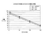
図3は、等速加圧に必要な流量を示すグラフである。図3を参照して、圧電ポンプ31を一定電圧で制御する場合、電圧のピーク間電位差が15Vp-pのときは、カフ圧が約0mmHgのときは、圧電ポンプ31から吐出される流量が約50ml/minで、50mmHgのときは、約25ml/minで、110mmHgのときは、約0ml/minである。 FIG. 3 is a graph showing the flow rate required for constant speed pressurization. Referring to FIG. 3, when the
同様に、電圧のピーク間電位差が20Vp-pのときは、カフ圧が約0mmHg、50mmHg、100mmHg、150mmHg、170mmHgと上昇するに従って、圧電ポンプ31の吐出流量は、約100ml/min、約70ml/min、約30ml/min、約10ml/min、約0ml/minと減少する。 Similarly, when the voltage difference between the peaks of the voltage is 20 Vp-p, the discharge flow rate of the
さらに、圧電ポンプ31に印加する電圧のピーク間電位差が25Vp-p、30Vp-p、35Vp-p、40Vp-pである場合も、カフ圧の上昇に伴なって、圧電ポンプ31の吐出流量は、減少する。 Furthermore, when the potential difference between the peaks of the voltage applied to the
また、圧電ポンプ31でカフ40を等速加圧するときに必要な流量は、カフ40の装着部位である手首周がカフ40で対応可能な最小の長さである場合、カフ圧が30mmHgから250mmHgまで上昇する間に、約30ml/minから約35ml/minまで上昇する。 Further, when the
一方、手首周がカフ40で対応可能な最大の長さである場合、カフ圧が30mmHgのときは、等速加圧に必要な流量は、約145ml/minであるが、カフ圧の上昇とともに減少し、カフ圧が100mmHgのときは、約80ml/min、150mmHgのときは、約75ml/min、250mmHgのときは、約75ml/minである。On the other hand, when the wrist circumference is the maximum length that can be accommodated by the
手首周がカフ40で対応可能な最小の長さから最大の長さまでの間である場合は、図3のグラフの斜線でハッチングしている等速加圧制御範囲でカフ圧に対する流量を制御することによってカフ40を等速加圧することができる。When the wrist circumference is between the minimum length and the maximum length that can be handled by the
このため、手首周が最小である場合に、カフ圧の上昇に従って上述したように流量が変化するように制御して、カフ40を等速加圧する場合は、圧電ポンプ31に印加する電圧のピーク間電位差を、約14Vp-pからカフ圧の上昇に従って増加させ、カフ圧が250
mmHgに達したときには、約33Vp-pに制御する必要がある。For this reason, when the wrist circumference is the minimum, when the
When reaching mmHg, it is necessary to control to about 33 Vp-p.
また、手首周が最大である場合に、カフ圧の上昇に従って上述したように流量が変化するように制御して、カフ40を等速加圧する場合は、圧電ポンプ31に印加する電圧のピーク間電位差を、約26Vp-pからカフ圧が約60mmHgに達するぐらいまでに約23Vp-pに減少させ、その後増加させて、カフ圧が250mmHgに達したときには、約37Vp-pに制御する必要がある。In addition, when the wrist circumference is the maximum, when the
このように、カフ40を等速加圧するためには、ある電圧の振幅の範囲(ここでは、ピーク間電圧が凡そ12Vp-p〜40Vp-pの範囲、つまり、振幅の範囲が6V〜20V)で、圧電ポンプ31を電圧制御する必要がある。また、デジタル制御であるため、加圧速度の制御の精度を向上させるためには、制御電圧の分解能を向上させる必要がある。しかし、このためには、高価な制御回路を用いる必要があるので、血圧計1の製造コストの上昇につながってしまう。Thus, in order to pressurize the
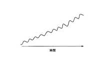
図4は、圧電ポンプ31の制御電圧をAM(Amplitude Modulation)変調した場合のカフ圧の変化を示すグラフである。図4を参照して、制御電圧の分解能を向上させるために、制御電圧をAM変調することが考えられる。 FIG. 4 is a graph showing the change in cuff pressure when the control voltage of the
しかし、このようにするとグラフで示すように増加するカフ圧に脈動が発生してしまう。このような脈動は、血圧計1による血圧測定に悪い影響(たとえば、測定精度の悪化)を与えてしまう。また、脈動が可聴範囲の周波数であれば、騒音が発生してしまう。そして、脈動の振幅が大きくなる程、騒音の音量も大きくなってしまう。 However, if this is done, pulsation occurs in the increasing cuff pressure as shown in the graph. Such pulsation adversely affects blood pressure measurement by the sphygmomanometer 1 (for example, deterioration in measurement accuracy). Further, if the pulsation is in an audible range, noise is generated. As the amplitude of pulsation increases, the volume of noise increases.
図5は、この発明の圧電ポンプ31の電圧制御の概念を示す図である。図5を参照して、この実施の形態における血圧計1は、圧電ポンプ31に印加する電圧等をデジタル制御するために、制御可能な電圧の振幅の値が段階的になる。たとえば、制御ステップが1Vである場合、目標電圧の振幅V0が、たとえば、20.3Vである場合、20Vや21Vを圧電ポンプ31に印加することはできるが、20.3Vを圧電ポンプに印加することができない。 FIG. 5 is a diagram showing the concept of voltage control of the
なお、10Vから40Vまでを、制御分解能10ビットで制御する場合、約30mVの制御ステップで制御することができ、5ビットで制御する場合、約1Vの制御ステップで制御することができる。 When controlling from 10 V to 40 V with a control resolution of 10 bits, it can be controlled with a control step of about 30 mV, and when controlling with 5 bits, it can be controlled with a control step of about 1 V.
この発明においては、このような場合に、ある周期1/f_amのうちの割合D1の期間を、振幅V1の駆動電圧およびその振幅V1の駆動電圧に対する最適周波数f1で駆動し、割合D2の期間を、振幅V2の駆動電圧およびその振幅V2の駆動電圧に対する最適周波数f2で駆動することによって、振幅V0の目標電圧で駆動した場合と略等価な流量を吐出するよう、圧電ポンプ31を制御する。 In the present invention, in such a case, the period of the ratio D1 in a
この実施の形態においては、V0=V1×D1+V2×D2(V2≦V0≦V1),D1+D2=1となるように、駆動電圧の振幅V1,V2およびDUTY比D1,D2が定められる。 In this embodiment, the drive voltage amplitudes V1, V2 and DUTY ratios D1, D2 are determined so that V0 = V1 * D1 + V2 * D2 (V2≤V0≤V1) and D1 + D2 = 1.
なお、f_amは、図4で説明したようなAM変調(振幅変調)の周波数と同程度の周波数であり、たとえば、30Hz程度から200Hz程度の値であるが、血圧の脈波成分が30Hz以下の周波数に含まれるため、30Hzよりも大きい周波数である必要があるが、圧電ポンプの駆動周波数(たとえば、20kHz前後の値)よりも小さい周波数であれば、他の周波数であってもよい。 Note that f_am is the same frequency as the AM modulation (amplitude modulation) frequency described with reference to FIG. 4, for example, a value of about 30 Hz to about 200 Hz, but the blood pressure pulse wave component is 30 Hz or less. Since it is included in the frequency, it is necessary that the frequency be higher than 30 Hz. However, other frequencies may be used as long as the frequency is lower than the driving frequency of the piezoelectric pump (for example, a value around 20 kHz).
f_amの値が高くなれば、制御の応答性が良くなるが、制御部20の処理負荷が高くなるため、f_amの値は、制御部20の処理速度に基づいて定められる。 As the value of f_am increases, the control responsiveness improves, but the processing load on the
また、V1とV2との差は、できるだけ小さいほうが、脈動による騒音を抑えることができたり、騒音の音量を小さくすることができたりする。 Further, when the difference between V1 and V2 is as small as possible, noise due to pulsation can be suppressed or the volume of noise can be reduced.
たとえば、目標電圧の振幅V0=20.3Vであり、V1=21V、V2=20Vとした場合、V0=V1×D1+V2×D2、D1+D2=1の関係より、DUTY比D1=0.3、D2=0.7と算出することができる。 For example, when the amplitude of the target voltage is V0 = 20.3V, V1 = 21V, and V2 = 20V, DUTY ratio D1 = 0.3, D2 = from the relationship of V0 = V1 × D1 + V2 × D2, D1 + D2 = 1. It can be calculated as 0.7.
また、目標電圧の振幅V0=20.5Vであり、DUTY比D1=D2=0.5で固定とした場合、V0=V1×D1+V2×D2、D1+D2=1の関係より、V1+V2=41と算出することができる。この場合、V1,V2は、さまざまな組合せとすることができ、たとえば、V1=29V、V2=12Vとしてもよいし、V1=22V、V2=19Vとしてもよい。ただし、上述したように、V1とV2との差はできるだけ小さい方がよいので、後者の方が望ましい。 When the target voltage amplitude V0 = 20.5V and the DUTY ratio D1 = D2 = 0.5 is fixed, V1 + V2 = 41 is calculated from the relationship of V0 = V1 * D1 + V2 * D2 and D1 + D2 = 1. be able to. In this case, V1 and V2 can be various combinations. For example, V1 = 29V and V2 = 12V, or V1 = 22V and V2 = 19V. However, as described above, the difference between V1 and V2 is preferably as small as possible, so the latter is preferable.
図6は、この発明の実施の形態にしたがって圧電ポンプ31を電圧制御した場合の制御結果を説明するためのグラフである。図6を参照して、一点鎖線で示したグラフ、および、破線で示したグラフは、それぞれ、20Vおよび21Vで圧電ポンプ31を駆動した場合の加圧過程における圧電ポンプ31の吐出流量の変化を示す。 FIG. 6 is a graph for explaining the control result when the voltage of the
また、実線で示したグラフは、目標電圧が20.5Vである場合に、20Vと21VとをDUTY比50%で切替えて圧電ポンプ31を駆動した場合の加圧過程における圧電ポンプ31の吐出流量の変化を示す。このように、目標電圧20.5Vで20Vと21Vとを切替えて制御した場合、20Vで駆動した場合と、21Vで駆動した場合とのちょうど中間あたりの吐出流量となることが示されている。 The graph shown by the solid line shows the discharge flow rate of the
図7は、第1の実施の形態における血圧計1で実行される血圧測定処理の流れを示すフローチャートである。図7を参照して、ステップS111で、制御部20は、カフ40の巻付け状態(手首周、きつく巻いているか緩く巻いているか)、現在のカフ圧、および、等速加圧に必要な流量から、メモリ部22に予め記憶されてる図3で示したグラフで示されるようなデータに基づいて、圧電ポンプ31の目標電圧の振幅Vを決定する。 FIG. 7 is a flowchart showing the flow of blood pressure measurement processing executed by the
次に、ステップS112で、制御部20は、図5で説明した方法にしたがって、所定のAM変調周波数f_amの周期1/f_amのうちで、目標電圧V0と同様の流量を吐出するために、駆動電圧V1,V2を切替えて制御する場合のV1,V2およびDUTY比D1,D2を算出する。 Next, in step S112, the
ステップS113では、制御部20は、ステップS112で算出したV1,V2が|V1−V2|≦Limitの関係を満たすか否か、つまり、V1とV2との差がLimit以下であるか否かを判断する。Limit以下でないと判断した場合(ステップS113でNOと判断した場合)、制御部20は、実行する処理をステップS112の処理に戻す。 In step S113, the
一方、|V1−V2|≦Limitの関係を満たすと判断した場合(ステップS113でYESと判断した場合)、ステップS114で、制御部20は、メモリ部22に予め記憶された圧電ポンプ31の特性データに基づいて、ステップS112で算出したV1,V2に適応する最適周波数f1,f2を決定する。ここでは、最適周波数は、最大流量を吐出することができる周波数であることとするが、ポンプ効率を最大とする周波数であってもよい。 On the other hand, if it is determined that | V1−V2 | ≦ Limit is satisfied (YES in step S113), in step S114, the
次に、ステップS121で、ステップS112で算出した駆動電圧V1、および、ステップS114で算出した駆動周波数f1で、時間D1/f_amの間、圧電ポンプ31を駆動するよう、電圧制御回路62に電圧値を示す信号を送信するとともに駆動制御回路63に駆動周波数を示す信号を送信する。 Next, in step S121, the voltage value is supplied to the
次いで、ステップS122で、ステップS112で算出した駆動電圧V2、および、ステップS114で算出した駆動周波数f2で、時間D2/f_amの間、圧電ポンプ31を駆動するよう、電圧制御回路62に電圧値を示す信号を送信するとともに駆動制御回路63に駆動周波数を示す信号を送信する。 Next, in step S122, the voltage value is supplied to the
次に、ステップS123で、制御部20は、圧力センサ33で検出され、増幅器71およびA/D変換器72を介して制御部20に入力された信号によって示されるカフ圧の変化に基づいて、従来の方法で、血圧値を算出する。 Next, in step S123, the
そして、ステップS124で、制御部20は、血圧測定が完了したか否かを判断する。血圧測定が完了していないと判断した場合(ステップS124でNOと判断した場合)、制御部20は、実行する処理をステップS111の処理に戻す。 In step S124, the
一方、血圧測定が完了したと判断した場合(ステップS124でYESと判断した場合)、ステップS125で、制御部20は、圧電ポンプ31の駆動を停止するよう、電圧制御回路62および駆動制御回路63を制御する。 On the other hand, when it is determined that the blood pressure measurement has been completed (when YES is determined in step S124), in step S125, the
次に、ステップS126で、制御部20は、血圧測定結果を表示するよう表示部21を制御する。ステップS126の後、制御部20は、血圧測定処理を終了させる。 Next, in step S126, the
[第2の実施の形態]
図8は、第2の実施の形態における血圧計1で実行される血圧測定処理の流れを示すフローチャートである。図8を参照して、ステップS131は、第1の実施の形態の図7で説明したステップS111の処理と同様であるので、重複する説明は繰返さない。[Second Embodiment]
FIG. 8 is a flowchart showing the flow of blood pressure measurement processing executed by the
次に、ステップS132で、制御部20は、ステップS131で算出した目標電圧V0に対して制御可能分解能の1つ上の電圧V1および1つ下の電圧V2を決定する。たとえば、制御可能分解能が1V単位で目標電圧V0=20.3Vである場合、V1=21V,V2=20Vと決定する。 Next, in step S132, the
次いで、ステップS133で、制御部20は、図5で説明した方法にしたがって、所定のAM変調周波数f_amの周期1/f_amのうちで、目標電圧V0と同様の流量を吐出するために、ステップS132で決定した駆動電圧V1,V2を切替えて制御する場合のDUTY比D1,D2を算出する。 Next, in step S133, the
そして、ステップS134で、制御部20は、メモリ部22に予め記憶された圧電ポンプ31の特性データに基づいて、ステップS132で算出したV1,V2に適応する最適周波数f1,f2を決定する。 In step S134, the
ステップS121からステップS126までの処理は、図7で説明した処理と同様であるので、重複する説明は繰返さない。 Since the process from step S121 to step S126 is the same as the process demonstrated in FIG. 7, the overlapping description is not repeated.
以上説明したように、この実施の形態における血圧計1は、以下に示すような効果を発揮する。 As described above, the
(1) 血圧計1は、血圧の測定部位に装着された場合に内部の流体の圧力で測定部位の動脈を圧迫するカフ40と、カフ40の内部の圧力を加圧する圧電ポンプ31と、カフの内部の圧力を減圧する排気弁32と、カフ40の内部の圧力であるカフ圧を検出する圧力センサ33と、制御部20とを有する。 (1) The
制御部20は、図7のステップS111からステップS114、図8のステップS131からステップS134で示したように、圧電ポンプ31に印加する電圧の制御振幅と制御周波数とを決定し、図7、図8のステップS121、ステップS122で示したように、決定された制御振幅V1,V2および制御周波数f1,f2の電圧を圧電ポンプ31に印加するよう制御し、図7、図8のステップS123で示したように、圧電ポンプ31によってカフ圧を加圧する加圧過程において圧力センサ33によって検出されるカフ圧に基づいて血圧値を算出する。また、図7のステップS111、ステップS112、図8のステップS131からステップS133、図7、図8のステップS121、ステップS122で示したように、制御部20は、電圧の振幅を所定段階で制御可能であり、決定された制御振幅V0の電圧を印加した場合と圧電ポンプ31の出力が略等価になるように、制御振幅の上の少なくとも1つの段階の値V1および下の少なくとも1つの段階の値V2の振幅の電圧を、所定の順番で印加する。 The
印加する電圧をAM変調することによって目標電圧が印加された場合と吐出流量が略等価になるように圧電ポンプ31を制御することもできる。しかし、この実施の形態の血圧計1によれば、AM変調により制御する場合と比較して、AM変調の周波数の騒音の発生を抑制させることができる。また、AM変調により制御する場合は、加圧されるカフ圧に脈動が発生するが、この実施の形態の血圧計1によれば、脈動の影響を低減させることができる。さらに、この実施の形態の血圧計1によれば、AM変調により制御する場合と同様に精度の高い加圧制御をすることができる。 The
その結果、血圧測定のための加圧過程において圧電ポンプ31を用いて加圧制御する場合に、騒音の発生を抑制させること、ならびに、脈動の影響の低減および精度の高い加圧制御により血圧測定精度を向上させることができる。 As a result, when pressurization control is performed using the
(2) 第2の実施の形態において、図8のステップS121、ステップS122で示したように、制御部20は、2つの値の振幅の電圧を、交互に印加する。2つの値は、決定された制御振幅V0の、所定段階(第2の実施の形態では「1」段階)、上の値V1、および、所定段階、下の値V2である。また、制御部20は、図8のステップS133で示したように、決定された制御振幅V0および2つの値V1,V2に基づいて、制御振幅V0の電圧を印加した場合と圧電ポンプ31の出力が略等価になるように、2つの値V1,V2の電圧を交互に印加する時間的割合D1,D2を決定する。そして、制御部20は、図8のステップS121、ステップS122で示したように、決定された時間的割合D1,D2で、2つの値V1,V2の振幅の電圧を印加する。 (2) In the second embodiment, as shown in step S121 and step S122 in FIG. 8, the
このようにすれば、同じ所定数上下の段階の値V1,V2を決定するので、異なる上下の段階の値を決定する場合と比較して、印加する電圧の振幅を決定し易くすることができる。 In this way, since the same predetermined number of upper and lower step values V1 and V2 are determined, it is possible to make it easier to determine the amplitude of the applied voltage as compared to the case where different upper and lower step values are determined. .
(3) さらに、図8のステップS132、ステップS121、ステップS122で示したように、制御部20は、2つの値V1,V2の差が最小となるように電圧を印加する。 (3) Further, as shown in step S132, step S121, and step S122 of FIG. 8, the
これにより、脈動による騒音を抑えることができたり、騒音の音量を小さくすることができたりする。 Thereby, noise due to pulsation can be suppressed, or the volume of noise can be reduced.
(4) 第1の実施の形態の図5において示したように、制御部20は、決定された2つの値V1,V2の振幅の電圧を、同じ時間的割合D1=D2=0.5で交互に印加するようにしてもよい。図7のステップS112で示したように、制御部20は、決定された制御振幅V0に基づいて、制御振幅V0の電圧を印加した場合と圧電ポンプ31の出力が略等価になるように、制御振幅V0の、上の段階の値V1および下の段階の値V2の2つの値を決定する。図7のステップS121、ステップS122で示したように、制御部20は、決定された2つの値V1,V2の振幅の電圧を交互に印加する。 (4) As shown in FIG. 5 of the first embodiment, the
(5) 図7のステップS113では、制御部20は、2つの値V1,V2の差が所定の値Limit以下であるか否かを判断し、以下でない場合は、2つの値V1,V2を再決定し、2つの値V1,V2の差がLimit以下となるようにした。さらに、制御部20は、2つの値の差が最小となるように値を決定するようにしてもよい。 (5) In step S113 of FIG. 7, the
2つの値V1,V2の差をLimit以下とする場合および最小とする場合のいずれであっても、脈動による騒音を抑えることができたり、騒音の音量を小さくすることができたりする。 Regardless of whether the difference between the two values V1 and V2 is less than or equal to Limit, noise due to pulsation can be suppressed or the volume of the noise can be reduced.
(6) 図7のステップS114、図8のステップS134で示したように、制御部20は、印加される電圧の振幅の値V1,V2に対して最適な周波数f1,f2を制御周波数として決定する。 (6) As shown in step S114 in FIG. 7 and step S134 in FIG. 8, the
これにより、複数の振幅の電圧を切替えて印加する場合であっても、それぞれの電圧の場合に最適な周波数を印加することができる。このため、いずれのタイミングでも圧電ポンプ31を最適に制御することができる。 Thereby, even if it is a case where the voltage of a some amplitude is switched and applied, the optimal frequency can be applied in the case of each voltage. For this reason, the
次に、上述した実施の形態の変形例を記載する。
(1) 前述した実施の形態においては、圧電ポンプ31からカフ40に供給される流体は、空気であることとした。しかし、これに限定されず、圧電ポンプ31からカフ40に供給される流体は、他の流体、たとえば、液体またはゲルであってもよい。あるいは、流体に限定されるものではなく、マイクロビーズなどの均一な微粒子であってもよい。Next, a modification of the above-described embodiment will be described.
(1) In the above-described embodiment, the fluid supplied from the
(2) 前述した実施の形態においては、測定部位の大きさが手首周であることとしたが、これに限定されず、測定部位が異なれば、異なる大きさとなる。たとえば、測定部位が腕である場合は、腕周となる。 (2) In the above-described embodiment, the size of the measurement site is the wrist circumference. However, the measurement site is not limited to this. If the measurement site is different, the measurement site has a different size. For example, when the measurement site is an arm, it is the arm circumference.
(3) 前述した実施の形態においては、図7および図8で示したように、制御目標V0を決定してV1,V2,f1,f2などの制御パラメータを更新する周期、および、血圧値を算出する周期が、D1/f_am+D2/f_am=1/f_amの周期ごと、つまり、DUTY制御の1周期ごとであることとした。しかし、これに限定されず、制御パラメータの更新、および、血圧値の算出の周期が、DUTY制御の複数周期ごとであることとしてもよい。 (3) In the above-described embodiment, as shown in FIGS. 7 and 8, the cycle for determining the control target V0 and updating the control parameters such as V1, V2, f1, and f2, and the blood pressure value are set. It is assumed that the calculation cycle is every cycle of D1 / f_am + D2 / f_am = 1 / f_am, that is, every cycle of the DUTY control. However, the present invention is not limited to this, and the control parameter update and blood pressure value calculation cycle may be every multiple cycles of DUTY control.
(4) 前述した第1の実施の形態においては、図7のステップS112で、電圧の振幅V1,V2を先に決定して、それに対して、DUTY比D1,D2を算出するようにしていもよいし、DUTY比D1,D2を先に決定して、それに対して、電圧の振幅V1,V2を算出するようにしてもよい。 (4) In the first embodiment described above, the amplitudes V1 and V2 of the voltage are determined first in step S112 of FIG. 7, and the DUTY ratios D1 and D2 are calculated for that. Alternatively, the DUTY ratios D1 and D2 may be determined first, and the voltage amplitudes V1 and V2 may be calculated.
(5) 前述した実施の形態においては、2つの電圧の振幅V1,V2を切替えて制御する場合について説明した。しかし、これに限定されず、3つ以上の電圧の振幅を切替えながら制御してもよい。たとえば、20.5Vの振幅の目標電圧と等価な流量を吐出できるよう、19V、20V、21V、22Vの4つの電圧の振幅を、それぞれ、0.25のDUTY比で順番に切替えて、制御してもよい。 (5) In the embodiment described above, the case where the amplitudes V1 and V2 of the two voltages are switched and controlled has been described. However, the present invention is not limited to this, and control may be performed while switching the amplitude of three or more voltages. For example, the amplitude of four voltages of 19V, 20V, 21V, and 22V is switched in order with a DUTY ratio of 0.25, respectively, so that a flow rate equivalent to a target voltage with an amplitude of 20.5V can be discharged. May be.
(6) 前述した第2の実施の形態においては、図8のステップS132で説明したように、目標電圧V0に対して制御可能分解能の1つ上の電圧V1および1つ下の電圧V2を決定するようにした。これにより、V1とV2との差が最小となるように電圧を印加することができる。しかし、これに限定されず、目標電圧V0に対して制御分解能の2つ以上、上および下の電圧を決定するようにしてもよい。たとえば、目標電圧V0=20.3Vに対して、制御可能分解能の5つ上の電圧V1=25V、5つ下の電圧V2=16Vを決定する。V1とV2との差が前述したLimit以下であれば、脈動による騒音を悪化させることはない。 (6) In the above-described second embodiment, as described in step S132 of FIG. 8, the voltage V1 that is one higher than the controllable resolution and the voltage V2 that is one lower than the target voltage V0 are determined. I tried to do it. Thereby, a voltage can be applied so that the difference between V1 and V2 is minimized. However, the present invention is not limited to this, and two or more control resolution voltages above and below the target voltage V0 may be determined. For example, with respect to the target voltage V0 = 20.3V, a voltage V1 = 25V, which is five higher than the controllable resolution, and a voltage V2 = 16V, which is five lower, are determined. If the difference between V1 and V2 is equal to or less than the aforementioned Limit, noise due to pulsation is not deteriorated.
(7) 前述した実施の形態においては、血圧計1の装置として発明を説明した。しかし、これに限定されず、血圧計1の制御方法として発明を捉えることができる。また、血圧計1の制御プログラムとして発明を捉えることができる。 (7) In the above-described embodiment, the invention has been described as an apparatus of the
(8) 今回開示された実施の形態はすべての点で例示であって制限的なものではないと考えられるべきである。本発明の範囲は、上記した説明ではなく、特許請求の範囲によって示され、特許請求の範囲と均等の意味および範囲内でのすべての変更が含まれることが意図される。 (8) The embodiment disclosed this time should be considered as illustrative in all points and not restrictive. The scope of the present invention is defined by the terms of the claims, rather than the description above, and is intended to include any modifications within the scope and meaning equivalent to the terms of the claims.
1 血圧計、10 本体、20 制御部、21 表示部、22 メモリ部、23 操作部、24 電源部、31 圧電ポンプ、32 排気弁、33 圧力センサ、40 カフ、41 外装カバー、42 圧迫用空気袋、50 エア管、61 DC−DC昇圧回路、62 電圧制御回路、63 駆動制御回路、71 増幅器、72 変換器。 DESCRIPTION OF
Claims (7)
Translated fromJapanese前記カフの内部の圧力を加圧する圧電ポンプと、
前記カフの内部の圧力を減圧する減圧部と、
前記カフの内部の圧力であるカフ圧を検出する圧力検出部と、
制御部とを有し、
前記制御部は、
前記圧電ポンプに印加する電圧の制御振幅と制御周波数とを決定する決定手段と、
前記決定手段によって決定された前記制御振幅および前記制御周波数の電圧を前記圧電ポンプに印加するよう制御する印加電圧制御手段と、
前記圧電ポンプによって前記カフ圧を加圧する加圧過程において前記圧力検出部によって検出されるカフ圧に基づいて血圧値を算出する血圧測定手段とを含み、
前記印加電圧制御手段は、電圧の振幅を所定段階で制御可能であり、前記決定手段によって決定された前記制御振幅の電圧を印加した場合と前記圧電ポンプの出力が略等価になるように、前記制御振幅の上の少なくとも1つの段階の値および下の少なくとも1つの段階の値の振幅の電圧を、所定の順番で印加する、血圧測定装置。A cuff that compresses the artery of the measurement site with the pressure of the internal fluid when attached to the measurement site of blood pressure;
A piezoelectric pump for pressurizing the pressure inside the cuff;
A decompression section for reducing the pressure inside the cuff;
A pressure detector that detects a cuff pressure that is an internal pressure of the cuff;
A control unit,
The controller is
Determining means for determining a control amplitude and a control frequency of a voltage applied to the piezoelectric pump;
Applied voltage control means for controlling the voltage of the control amplitude and the control frequency determined by the determining means to be applied to the piezoelectric pump;
Blood pressure measuring means for calculating a blood pressure value based on the cuff pressure detected by the pressure detector in the pressurizing process of pressurizing the cuff pressure by the piezoelectric pump;
The applied voltage control means can control the amplitude of the voltage at a predetermined stage, and the output of the piezoelectric pump is substantially equivalent to the case where the voltage of the control amplitude determined by the determination means is applied. A blood pressure measurement device that applies a voltage having an amplitude of at least one level above the control amplitude and an amplitude of at least one level below the control amplitude in a predetermined order.
前記2つの値は、それぞれ、前記決定手段によって決定された前記制御振幅に対して、所定段階、上の値、および、前記所定段階、下の値であり、
前記制御部は、さらに、
前記決定手段によって決定された前記制御振幅および前記2つの値に基づいて、前記制御振幅の電圧を印加した場合と前記圧電ポンプの出力が略等価になるように、前記2つの値の電圧を交互に印加する時間的割合を決定する印加割合決定手段を含み、
前記印加電圧制御手段は、前記印加割合決定手段によって決定された前記時間的割合で、前記2つの値の振幅の電圧を印加する、請求項1に記載の血圧測定装置。The applied voltage control means alternately applies voltages having two values of amplitude,
The two values are a predetermined level, an upper value, and a predetermined level and a lower value, respectively, with respect to the control amplitude determined by the determining means.
The control unit further includes:
Based on the control amplitude and the two values determined by the determining means, the voltage of the two values is alternately changed so that the output of the piezoelectric pump is substantially equivalent to the case where the voltage of the control amplitude is applied. Including an application rate determining means for determining a time rate to be applied to
The blood pressure measurement device according to claim 1, wherein the applied voltage control means applies a voltage having an amplitude of the two values at the time ratio determined by the application ratio determining means.
前記制御部は、さらに、
前記決定手段によって決定された前記制御振幅に基づいて、前記制御振幅の電圧を印加した場合と前記圧電ポンプの出力が略等価になるように、前記制御振幅の、上の段階の値および下の段階の値の前記2つの値を決定する印加電圧決定手段を含み、
前記印加電圧制御手段は、前記印加電圧決定手段によって決定された前記2つの値の振幅の電圧を交互に印加する、請求項1に記載の血圧測定装置。The applied voltage control means alternately applies voltages having amplitudes of two values determined by the determining means at the same time ratio,
The control unit further includes:
Based on the control amplitude determined by the determining means, when the voltage of the control amplitude is applied and the output of the piezoelectric pump is substantially equivalent, the value of the upper stage of the control amplitude and An applied voltage determining means for determining the two values of the stage value;
The blood pressure measurement device according to claim 1, wherein the applied voltage control unit alternately applies voltages having amplitudes of the two values determined by the applied voltage determination unit.
前記血圧測定装置は、
血圧の測定部位に装着された場合に内部の流体の圧力で前記測定部位の動脈を圧迫するカフと、
前記カフの内部の圧力を加圧する圧電ポンプと、
前記カフの内部の圧力を減圧する減圧部と、
前記カフの内部の圧力であるカフ圧を検出する圧力検出部と、
制御部とを有し、
前記制御方法は、前記制御部が、
前記圧電ポンプに印加する電圧の制御振幅と制御周波数とを決定するステップと、
決定された前記制御振幅および前記制御周波数の電圧を前記圧電ポンプに印加するよう制御するステップと、
前記圧電ポンプによって前記カフ圧を加圧する加圧過程において前記圧力検出部によって検出されるカフ圧に基づいて血圧値を算出するステップとを含み、
前記制御するステップは、電圧の振幅を所定段階で制御可能であり、決定された前記制御振幅の電圧を印加した場合と前記圧電ポンプの出力が略等価になるように、前記制御振幅の上の少なくとも1つの段階の値および下の少なくとも1つの段階の値の振幅の電圧を、所定の順番で印加するステップを含む、前記血圧測定装置の制御方法。A method for controlling a blood pressure measurement device, comprising:
The blood pressure measurement device includes:
A cuff that compresses the artery of the measurement site with the pressure of the internal fluid when attached to the measurement site of blood pressure;
A piezoelectric pump for pressurizing the pressure inside the cuff;
A decompression section for reducing the pressure inside the cuff;
A pressure detector that detects a cuff pressure that is an internal pressure of the cuff;
A control unit,
In the control method, the control unit
Determining a control amplitude and a control frequency of a voltage applied to the piezoelectric pump;
Controlling the voltage of the determined control amplitude and the control frequency to be applied to the piezoelectric pump;
Calculating a blood pressure value based on the cuff pressure detected by the pressure detector in a pressurizing process of pressurizing the cuff pressure by the piezoelectric pump,
In the controlling step, the amplitude of the voltage can be controlled at a predetermined stage, and theoutput of the piezoelectric pump is approximately equivalent to the case where the voltage of the determined control amplitude is applied, and the control amplitude is increased. A method of controlling the blood pressure measurement device, comprising applying a voltage having an amplitude of at least one stage value and at least one stage value below in a predetermined order.
Priority Applications (5)
| Application Number | Priority Date | Filing Date | Title |
|---|---|---|---|
| JP2012006089AJP5884496B2 (en) | 2012-01-16 | 2012-01-16 | Blood pressure measuring device and method for controlling blood pressure measuring device |
| DE112012005676.0TDE112012005676B4 (en) | 2012-01-16 | 2012-10-26 | Blood pressure measuring device and control method for the blood pressure measuring device |
| US14/371,795US9198584B2 (en) | 2012-01-16 | 2012-10-26 | Blood pressure measurement device and control method for blood pressure measurement device |
| CN201280056197.XACN103930019B (en) | 2012-01-16 | 2012-10-26 | Blood pressure measuring device and control method of blood pressure measuring device |
| PCT/JP2012/077710WO2013108460A1 (en) | 2012-01-16 | 2012-10-26 | Blood pressure measurement device and blood pressure measurement device control method |
Applications Claiming Priority (1)
| Application Number | Priority Date | Filing Date | Title |
|---|---|---|---|
| JP2012006089AJP5884496B2 (en) | 2012-01-16 | 2012-01-16 | Blood pressure measuring device and method for controlling blood pressure measuring device |
Publications (3)
| Publication Number | Publication Date |
|---|---|
| JP2013144054A JP2013144054A (en) | 2013-07-25 |
| JP2013144054A5 JP2013144054A5 (en) | 2015-02-26 |
| JP5884496B2true JP5884496B2 (en) | 2016-03-15 |
Family
ID=48798897
Family Applications (1)
| Application Number | Title | Priority Date | Filing Date |
|---|---|---|---|
| JP2012006089AActiveJP5884496B2 (en) | 2012-01-16 | 2012-01-16 | Blood pressure measuring device and method for controlling blood pressure measuring device |
Country Status (5)
| Country | Link |
|---|---|
| US (1) | US9198584B2 (en) |
| JP (1) | JP5884496B2 (en) |
| CN (1) | CN103930019B (en) |
| DE (1) | DE112012005676B4 (en) |
| WO (1) | WO2013108460A1 (en) |
Families Citing this family (22)
| Publication number | Priority date | Publication date | Assignee | Title |
|---|---|---|---|---|
| US7553295B2 (en) | 2002-06-17 | 2009-06-30 | Iradimed Corporation | Liquid infusion apparatus |
| US8105282B2 (en) | 2007-07-13 | 2012-01-31 | Iradimed Corporation | System and method for communication with an infusion device |
| TWI611103B (en)* | 2016-02-03 | 2018-01-11 | 研能科技股份有限公司 | Control method of driving circuit of piezoelectric actuated pump and driving circuit thereof |
| CN107040164B (en)* | 2016-02-03 | 2020-05-26 | 研能科技股份有限公司 | Control method and drive circuit |
| TWI604821B (en)* | 2016-11-11 | 2017-11-11 | Microlife Corp | Blood pressure measuring device with piezoelectric pump and control method for blood pressure measuring device with piezoelectric pump |
| US10874307B2 (en) | 2017-01-24 | 2020-12-29 | Verily Life Sciences Llc | Digital artery blood pressure monitor |
| US10313963B2 (en)* | 2017-02-27 | 2019-06-04 | Samsung Electronics Co., Ltd. | Methods for selecting radio access technology (RAT) modes in wireless communication devices |
| CN110213990B (en)* | 2017-03-16 | 2022-04-26 | 株式会社村田制作所 | Fluid control device and sphygmomanometer |
| EP4613214A2 (en) | 2017-04-18 | 2025-09-10 | Edwards Lifesciences Corporation | Heart valve sealing devices and delivery devices therefor |
| CN107126200A (en)* | 2017-06-23 | 2017-09-05 | 深圳市永盟智能信息系统有限公司 | Sphygmomanometer system and detection method |
| CN107536605B (en)* | 2017-09-05 | 2020-05-05 | 广州视源电子科技股份有限公司 | PWM circuit duty ratio adjusting method, controller and blood pressure measuring device |
| CN107479446A (en)* | 2017-09-11 | 2017-12-15 | 深圳市景新浩科技有限公司 | A kind of stable piezoelectric pump access power-supply controller of electric of new type of safe |
| US11553848B2 (en)* | 2017-09-29 | 2023-01-17 | Fitbit, Inc. | Devices and methods for controlling inflation rate in blood pressure measurements |
| US11268506B2 (en) | 2017-12-22 | 2022-03-08 | Iradimed Corporation | Fluid pumps for use in MRI environment |
| CN109938749B (en)* | 2019-04-03 | 2021-09-14 | 李�浩 | Artery position detection device and using method thereof |
| TWI697200B (en)* | 2019-04-03 | 2020-06-21 | 研能科技股份有限公司 | Micro piezoelectric pump module |
| GB2575945B (en)* | 2019-11-11 | 2023-02-08 | Ttp Ventus Ltd | System for non-invasive blood pressure measurement |
| US20220015652A1 (en)* | 2020-07-14 | 2022-01-20 | Apple Inc. | Integrated Flexible Sensor for Blood Pressure Measurements |
| US11744476B2 (en) | 2020-08-20 | 2023-09-05 | Apple Inc. | Blood pressure measurement using device with piezoelectric sensor |
| JP7597438B2 (en)* | 2020-12-25 | 2024-12-10 | ミネベアミツミ株式会社 | PUMP SYSTEM, FLUID SUPPLY DEVICE, AND DRIVE CONTROL METHOD FOR PUMP SYSTEM - Patent application |
| US12251204B2 (en) | 2021-02-03 | 2025-03-18 | Apple Inc. | Blood pressure monitoring system including a liquid filled sensor |
| JP2025136434A (en)* | 2024-03-07 | 2025-09-19 | オムロンヘルスケア株式会社 | Blood pressure measurement device, blood pressure measurement method, and blood pressure measurement program |
Family Cites Families (20)
| Publication number | Priority date | Publication date | Assignee | Title |
|---|---|---|---|---|
| JP2639764B2 (en)* | 1991-10-08 | 1997-08-13 | 株式会社半導体エネルギー研究所 | Display method of electro-optical device |
| JPH05146414A (en) | 1991-11-27 | 1993-06-15 | Sharp Corp | Blood pressure measuring instrument |
| JPH05164414A (en)* | 1991-12-13 | 1993-06-29 | Mitsubishi Electric Corp | Refrigeration cycle equipment |
| JP3595589B2 (en)* | 1995-01-09 | 2004-12-02 | コーリンメディカルテクノロジー株式会社 | Blood pressure monitoring device |
| US6428134B1 (en)* | 1998-06-12 | 2002-08-06 | Eastman Kodak Company | Printer and method adapted to reduce variability in ejected ink droplet volume |
| JP3925858B2 (en)* | 2002-11-08 | 2007-06-06 | 日本精密測器株式会社 | Non-invasive blood pressure monitor |
| US7287965B2 (en)* | 2004-04-02 | 2007-10-30 | Adaptiv Energy Llc | Piezoelectric devices and methods and circuits for driving same |
| JP4607547B2 (en)* | 2004-11-02 | 2011-01-05 | 日本精密測器株式会社 | Pressure control method and pulse wave discrimination method for electronic sphygmomanometer |
| CN100488446C (en)* | 2005-07-14 | 2009-05-20 | 优盛医学科技股份有限公司 | Intelligent pressurization control device |
| JP4047898B1 (en)* | 2006-09-29 | 2008-02-13 | シチズンホールディングス株式会社 | Electronic blood pressure monitor |
| JP4213188B2 (en)* | 2007-02-06 | 2009-01-21 | シチズンホールディングス株式会社 | Electronic blood pressure monitor |
| JP4957480B2 (en) | 2007-09-20 | 2012-06-20 | 株式会社村田製作所 | Piezoelectric micro pump |
| JP5146996B2 (en)* | 2007-10-25 | 2013-02-20 | テルモ株式会社 | Blood pressure measurement device and control method thereof |
| EP2260316B1 (en)* | 2008-02-28 | 2013-10-02 | Koninklijke Philips N.V. | Automated non-magnetic medical monitor using piezoelectric ceramic diaphragm devices |
| JP4631921B2 (en)* | 2008-03-26 | 2011-02-16 | ソニー株式会社 | Piezoelectric element driving apparatus and piezoelectric element driving frequency control method |
| JP2010162487A (en) | 2009-01-16 | 2010-07-29 | Sony Corp | Piezo-electric vibration device system and electrical appliance |
| JP2010255447A (en) | 2009-04-22 | 2010-11-11 | Sony Corp | Air blowing device driving device and air blowing device driving method |
| TWI392478B (en)* | 2009-09-24 | 2013-04-11 | 私立中原大學 | A blood pressure monitor with a blood vessel sclerosis |
| CN201790806U (en)* | 2010-08-06 | 2011-04-13 | 深圳瑞光康泰科技有限公司 | Non-invasive blood pressure measurement device |
| US8721557B2 (en)* | 2011-02-18 | 2014-05-13 | Covidien Lp | Pattern of cuff inflation and deflation for non-invasive blood pressure measurement |
- 2012
- 2012-01-16JPJP2012006089Apatent/JP5884496B2/enactiveActive
- 2012-10-26CNCN201280056197.XApatent/CN103930019B/enactiveActive
- 2012-10-26WOPCT/JP2012/077710patent/WO2013108460A1/enactiveIP Right Grant
- 2012-10-26USUS14/371,795patent/US9198584B2/enactiveActive
- 2012-10-26DEDE112012005676.0Tpatent/DE112012005676B4/enactiveActive
Also Published As
| Publication number | Publication date |
|---|---|
| CN103930019B (en) | 2015-12-09 |
| US9198584B2 (en) | 2015-12-01 |
| JP2013144054A (en) | 2013-07-25 |
| US20150094602A1 (en) | 2015-04-02 |
| DE112012005676B4 (en) | 2025-06-26 |
| CN103930019A (en) | 2014-07-16 |
| DE112012005676T5 (en) | 2014-10-02 |
| WO2013108460A1 (en) | 2013-07-25 |
| WO2013108460A9 (en) | 2014-05-30 |
Similar Documents
| Publication | Publication Date | Title |
|---|---|---|
| JP5884496B2 (en) | Blood pressure measuring device and method for controlling blood pressure measuring device | |
| JP5998486B2 (en) | Blood pressure measuring device and method for controlling blood pressure measuring device | |
| JP5200913B2 (en) | Electronic blood pressure monitor | |
| JP2013144054A5 (en) | ||
| JP5640527B2 (en) | Blood pressure measuring device | |
| JP5944727B2 (en) | Sphygmomanometer and pump drive system | |
| US9364156B2 (en) | Blood pressure measurement device and control method for blood pressure measurement device | |
| US7118535B2 (en) | Electronic blood pressure measurement device and blood pressure measuring method | |
| WO2013061780A1 (en) | Electronic sphygmomanometer | |
| WO2013157399A1 (en) | Blood pressure measuring device, control device in blood pressure measuring device, and control method of blood pressure measuring device | |
| JP6035838B2 (en) | Piezoelectric pump control device, piezoelectric pump control method, piezoelectric pump control program, and blood pressure measurement device | |
| JP2014014556A (en) | Electronic sphygmomanometer and sphygmomanometry method | |
| EP3752052B1 (en) | Controlling a wearable cuff | |
| CN114222523B (en) | Sphygmomanometer, blood pressure calculation method, and storage medium | |
| CN110891480B (en) | Measuring apparatus and measuring method | |
| JP7025917B2 (en) | Sphygmomanometer and its control method | |
| JP2017115792A (en) | Piezoelectric pump driving device and hemadynamometer provided with the same | |
| JP2012115413A (en) | Electronic sphygmomanometer | |
| JP2023088708A (en) | Biological information measuring device and sound wave communication system | |
| JP2011041684A (en) | Biological information measuring apparatus |
Legal Events
| Date | Code | Title | Description |
|---|---|---|---|
| A621 | Written request for application examination | Free format text:JAPANESE INTERMEDIATE CODE: A621 Effective date:20141222 | |
| A521 | Request for written amendment filed | Free format text:JAPANESE INTERMEDIATE CODE: A523 Effective date:20150109 | |
| TRDD | Decision of grant or rejection written | ||
| A01 | Written decision to grant a patent or to grant a registration (utility model) | Free format text:JAPANESE INTERMEDIATE CODE: A01 Effective date:20160112 | |
| A61 | First payment of annual fees (during grant procedure) | Free format text:JAPANESE INTERMEDIATE CODE: A61 Effective date:20160125 | |
| R150 | Certificate of patent or registration of utility model | Ref document number:5884496 Country of ref document:JP Free format text:JAPANESE INTERMEDIATE CODE: R150 |