JP5880340B2 - Headphone device, wearing state detection device, wearing state detection method - Google Patents
Headphone device, wearing state detection device, wearing state detection methodDownload PDFInfo
- Publication number
- JP5880340B2 JP5880340B2JP2012171975AJP2012171975AJP5880340B2JP 5880340 B2JP5880340 B2JP 5880340B2JP 2012171975 AJP2012171975 AJP 2012171975AJP 2012171975 AJP2012171975 AJP 2012171975AJP 5880340 B2JP5880340 B2JP 5880340B2
- Authority
- JP
- Japan
- Prior art keywords
- wearing state
- microphone
- sound
- wearing
- reference value
- Prior art date
- Legal status (The legal status is an assumption and is not a legal conclusion. Google has not performed a legal analysis and makes no representation as to the accuracy of the status listed.)
- Expired - Fee Related
Links
- 238000001514detection methodMethods0.000titleclaimsdescription113
- 230000005236sound signalEffects0.000claimsdescription206
- 238000012545processingMethods0.000claimsdescription114
- 238000000034methodMethods0.000claimsdescription61
- 230000008569processEffects0.000claimsdescription39
- 230000001186cumulative effectEffects0.000claimsdescription2
- 230000014509gene expressionEffects0.000description136
- 238000004364calculation methodMethods0.000description26
- 238000005259measurementMethods0.000description23
- 230000008929regenerationEffects0.000description8
- 238000011069regeneration methodMethods0.000description8
- 238000010586diagramMethods0.000description7
- 230000006870functionEffects0.000description7
- 238000012986modificationMethods0.000description5
- 230000004048modificationEffects0.000description5
- 238000013461designMethods0.000description4
- 230000000694effectsEffects0.000description4
- 238000005516engineering processMethods0.000description4
- 210000003128headAnatomy0.000description4
- 210000003027ear innerAnatomy0.000description3
- 230000015572biosynthetic processEffects0.000description2
- 230000007274generation of a signal involved in cell-cell signalingEffects0.000description2
- 238000009434installationMethods0.000description2
- 230000004044responseEffects0.000description2
- 239000000758substrateSubstances0.000description2
- 238000003786synthesis reactionMethods0.000description2
- 230000001131transforming effectEffects0.000description2
- 230000004913activationEffects0.000description1
- 230000003321amplificationEffects0.000description1
- 238000004458analytical methodMethods0.000description1
- 238000004891communicationMethods0.000description1
- 238000001914filtrationMethods0.000description1
- 230000007246mechanismEffects0.000description1
- 238000003199nucleic acid amplification methodMethods0.000description1
- 238000001228spectrumMethods0.000description1
- 238000012546transferMethods0.000description1
- 210000003454tympanic membraneAnatomy0.000description1
- 230000037303wrinklesEffects0.000description1
Images


Classifications
- H—ELECTRICITY
- H04—ELECTRIC COMMUNICATION TECHNIQUE
- H04R—LOUDSPEAKERS, MICROPHONES, GRAMOPHONE PICK-UPS OR LIKE ACOUSTIC ELECTROMECHANICAL TRANSDUCERS; DEAF-AID SETS; PUBLIC ADDRESS SYSTEMS
- H04R3/00—Circuits for transducers, loudspeakers or microphones
- H—ELECTRICITY
- H04—ELECTRIC COMMUNICATION TECHNIQUE
- H04R—LOUDSPEAKERS, MICROPHONES, GRAMOPHONE PICK-UPS OR LIKE ACOUSTIC ELECTROMECHANICAL TRANSDUCERS; DEAF-AID SETS; PUBLIC ADDRESS SYSTEMS
- H04R1/00—Details of transducers, loudspeakers or microphones
- H04R1/10—Earpieces; Attachments therefor ; Earphones; Monophonic headphones
- H04R1/1041—Mechanical or electronic switches, or control elements
- H—ELECTRICITY
- H04—ELECTRIC COMMUNICATION TECHNIQUE
- H04R—LOUDSPEAKERS, MICROPHONES, GRAMOPHONE PICK-UPS OR LIKE ACOUSTIC ELECTROMECHANICAL TRANSDUCERS; DEAF-AID SETS; PUBLIC ADDRESS SYSTEMS
- H04R2420/00—Details of connection covered by H04R, not provided for in its groups
- H04R2420/07—Applications of wireless loudspeakers or wireless microphones
- H—ELECTRICITY
- H04—ELECTRIC COMMUNICATION TECHNIQUE
- H04R—LOUDSPEAKERS, MICROPHONES, GRAMOPHONE PICK-UPS OR LIKE ACOUSTIC ELECTROMECHANICAL TRANSDUCERS; DEAF-AID SETS; PUBLIC ADDRESS SYSTEMS
- H04R2460/00—Details of hearing devices, i.e. of ear- or headphones covered by H04R1/10 or H04R5/033 but not provided for in any of their subgroups, or of hearing aids covered by H04R25/00 but not provided for in any of its subgroups
- H04R2460/03—Aspects of the reduction of energy consumption in hearing devices
- H—ELECTRICITY
- H04—ELECTRIC COMMUNICATION TECHNIQUE
- H04R—LOUDSPEAKERS, MICROPHONES, GRAMOPHONE PICK-UPS OR LIKE ACOUSTIC ELECTROMECHANICAL TRANSDUCERS; DEAF-AID SETS; PUBLIC ADDRESS SYSTEMS
- H04R3/00—Circuits for transducers, loudspeakers or microphones
- H04R3/005—Circuits for transducers, loudspeakers or microphones for combining the signals of two or more microphones
Landscapes
- Physics & Mathematics (AREA)
- Engineering & Computer Science (AREA)
- Acoustics & Sound (AREA)
- Signal Processing (AREA)
- Soundproofing, Sound Blocking, And Sound Damping (AREA)
- Headphones And Earphones (AREA)
- Circuit For Audible Band Transducer (AREA)
Description
Translated fromJapanese本開示はヘッドホン装置、及びヘッドホン装置が使用者に装着されているか否かを検出する装着状態検出装置、装着状態検出方法に関する。 The present disclosure relates to a headphone device, a wearing state detection device that detects whether or not the headphone device is worn by a user, and a wearing state detection method.
いわゆるノイズキャンセリングシステムを搭載したヘッドホンや、ブルートゥース(Bluetooth:登録商標)対応のワイヤレスヘッドホンなどのように、内部にアクティブ回路を含み、バッテリーを搭載しているヘッドホン(アクティブヘッドホン)がある。 There are headphones (active headphones) that include an active circuit and have a battery mounted therein, such as headphones equipped with a so-called noise canceling system and wireless headphones compatible with Bluetooth (registered trademark).
ユーザは、アクティブヘッドホンを使用した際、電源オフとすることを忘れることが往々にしてある。ヘッドホンを外したときに電源オフを忘れることで電池が消耗し、次に使用するときに電池が空になってしまっているということも多い。
アクティブヘッドホンでは専用の内蔵充電池を使用している製品もあり、電源消し忘れによって電池が空になってしまった場合、パッシヴに切り替えられない製品の場合は使用を諦めるか、外付け電池ボックスを使用したりなどユーザにとって不便である。
またパッシヴに切り替えられる製品もあるが、その場合でも、その製品の性能を最大限に生かした聴取ができないことになる。Users often forget to turn off power when using active headphones. If you forget to turn off the power when you remove the headphones, the battery will be exhausted, and the battery will often be empty the next time you use it.
Some active headphones use a dedicated built-in rechargeable battery. If the battery is empty due to forgetting to turn off the power, give up using the battery if the product cannot be switched to passive or use an external battery box. It is inconvenient for the user such as using it.
In addition, there are products that can be switched to passive, but even in that case, listening that makes the best use of the performance of the product is not possible.
上記の事情から、アクティブヘッドホンについて、装着/非装着を自動検出して、それに応じて適切な動作制御ができるようにすることが望ましい。 In view of the above circumstances, it is desirable to automatically detect wearing / non-wearing of active headphones so that appropriate operation control can be performed accordingly.
ヘッドホンの装着検出に関する技術はいくつか存在する。
例えば特許文献1のように、温度センサーを用いて装着検出を行うものや、特許文献2のように特別な機構(フック等)を備え、装着/非装着によるフックの開閉で電源制御を行うものがある。
ところが特許文献1の技術では、センサーの取り付け部分が使用者の使用方法に左右される。また特許文献2の技術はデザインに影響する。また、耳の中に装着するインナーイヤー型のヘッドホンの場合にはサイズの大型化が生ずるという制約も発生する。There are several technologies related to headphone wearing detection.
For example, as disclosed in
However, in the technique of
また特許文献3のように、再生されている音声信号のスペクトルを利用する方法も提案されているが、ノイズキャンセリングヘッドホンや通話機能付きブルートゥースヘッドホンの通話時などは、音声信号がない場合がある。
特許文献4のように、鼓膜からの反射音を解析する手法も提案されているが、これもノイズキャンセリングヘッドホンをノイズキャンセリングにのみ使用している(音楽等を聞いていない)場合に実行できない。反射音があるかどうかを判定するために何らかの音をドライバから出力する必要があり、ノイズキャンセリングとは背反の動作が必要となってしまう。
例えばユーザは、飛行機搭乗時などにノイズセリングヘッドホンのノイズキャンセル機能を利用して、外来音を遮断して読書や睡眠をするなどの利用形態もあるが、そのような利用を考慮すると、特許文献3,4のような再生出力されている音声を利用する手法は採れないこととなる。Also, as disclosed in
Although a method for analyzing the reflected sound from the eardrum has been proposed as in
For example, the user may use a noise canceling function of the noise selling headphone when boarding an airplane, etc. to cut off external sounds and read or sleep, but considering such use, Patent Literature A method of using reproduced and output audio such as 3 and 4 cannot be adopted.
そこで本開示では、音楽等の再生音声出力を実行していない場合でも的確に検出でき、またサイズやデザイン的な制約も殆ど生じない手法で、ヘッドホン装置の装着/非装着を適切に検出できるようにする手法を提供する。 Therefore, in the present disclosure, it is possible to accurately detect the output of reproduced audio such as music and the like, and to detect whether the headphone device is worn / not worn properly by a method that hardly causes size or design restrictions. Provide a method to make.
本開示のヘッドホン装置は、使用者に装着された状態で、外来音が遮蔽物を介さないで収音される位置に取り付けられる外側マイクロホンと、使用者に装着された状態で、外来音が遮蔽物を介して収音される位置に取り付けられる内側マイクロホンと、音響出力を行うドライバユニットと、装着状態検出部とを備える。装着状態検出部は、上記外側マイクロホンで得られる音声信号と上記内側マイクロホンで得られる音声信号との信号比較結果と、予め記憶した非装着状態における外来音到来時の上記外側マイクロホンで得られる音声信号と上記内側マイクロホンで得られる音声信号との信号比較結果である非装着状態基準値と、予め記憶した装着状態における外来音到来時の上記外側マイクロホンで得られる音声信号と上記内側マイクロホンで得られる音声信号との信号比較結果である装着状態基準値とを用いて、装着状態か非装着状態かを検出する。更に、装着状態検出部は、上記外側マイクロホンで得られる音声信号と上記内側マイクロホンで得られる音声信号との信号比較結果について、上記非装着状態基準値、及び上記装着状態基準値との各類似性判断を行って、装着状態か非装着状態かを検出する。
本開示の装着状態検出装置は、上記装着状態検出部の構成を備える。
The headphone device of the present disclosure includes an outer microphone that is attached to a position where foreign sounds are collected without passing through a shielding object when worn by the user, and a foreign sound that is shielded when worn by the user. An inner microphone that is attached to a position where sound is picked up via an object, a driver unit that outputs sound, and a mounting state detection unit are provided. The wearing state detection unit includes a signal comparison result between a sound signal obtained by the outer microphone and a sound signal obtained by the inner microphone, and a sound signal obtained by the outer microphone when a foreign sound arrives in a non-wearing state stored in advance. A non-wearing state reference value that is a signal comparison result between the sound signal obtained from the inner microphone and the sound signal obtained from the inner microphone, a sound signal obtained from the outer microphone and a sound obtained from the inner microphone when a foreign sound arrives in a wearing state stored in advance. Whether the wearing state or the non-wearing state is detected using the wearing state reference value which is a signal comparison result with the signal.In addition, the wearing state detection unit is similar to the non-wearing state reference value and the wearing state reference value for the signal comparison result between the sound signal obtained by the outer microphone and the sound signal obtained by the inner microphone. Judgment is made to detect whether the device is attached or not.
The mounting state detection device of the present disclosure includes the configuration of the mounting state detection unit.
本開示の装着状態検出方法は、使用者に装着された状態で、外来音が遮蔽物を介さないで収音される位置に取り付けられる外側マイクロホンと、使用者に装着された状態で、外来音が遮蔽物を介して収音される位置に取り付けられる内側マイクロホンと、音響出力を行うドライバユニットとを備えたヘッドホン装置の装着状態検出方法として、上記外側マイクロホンで得られる音声信号と上記内側マイクロホンで得られる音声信号との信号比較結果とについて、予め記憶した非装着状態における外来音到来時の上記外側マイクロホンで得られる音声信号と上記内側マイクロホンで得られる音声信号との信号比較結果である非装着状態基準値と、予め記憶した装着状態における外来音到来時の上記外側マイクロホンで得られる音声信号と上記内側マイクロホンで得られる音声信号との信号比較結果である装着状態基準値との各類似性判断を行って、装着状態か非装着状態かを検出する。
The wearing state detection method of the present disclosure includes an outer microphone that is attached to a position where an external sound is collected without passing through a shield while being worn by a user, and an external sound that is attached to the user. As a method for detecting the wearing state of a headphone device including an inner microphone attached to a position where sound is picked up via a shield and a driver unit that performs sound output, an audio signal obtained by the outer microphone and an inner microphone are used. Withrespect to the signal comparison result with the obtained audio signal, non-wearing that is a signal comparison result between the sound signal obtained with the outer microphone and the sound signal obtained with the inner microphone when a foreign sound arrives in a pre-stored non-wearing state The state reference value, the sound signal obtained by the outer microphone when the external sound arrives in the wearing state stored in advance,Performing the similarity determination and wearing state reference value is a signal comparison result between a sound signal obtained by themicrophone, to detect whether the mounting state or non-wearing state.
このような本開示では、ヘッドホン装置がユーザに装着された状態と、非装着の状態とで、内側マイクロホンで得られる外来音信号の信号特性が異なることを利用して、装着/非装着を検出する。
内側マイクロホンは、使用者に装着された状態で外来音が遮蔽物を介して収音される位置に取り付けられる。この場合の遮蔽物とは、例えばヘッドホンハウジングとなる。つまり内側マイクロホンで収音される外来音の信号特性は、装着/非装着により異なる。一方、外側マイクロホンは、装着/非装着に関わらず、外来音を直接収音する。
そして非装着状態では、内側マイクロホンと外側マイクロホンで得られる音声信号は、理想的には同様の特性となり、装着状態では内側マイクロホンと外側マイクロホンで得られる音声信号は、理想的には、その収音経路の差(遮蔽物の有無)に応じた異なる特性を示す。
従って、外側マイクロホンで得られる音声信号と内側マイクロホンで得られる音声信号との信号比較結果と、上記非装着状態基準値と、上記装着状態基準値とを用いることで装着状態か非装着状態かを検出することができる。In this disclosure, the wearing / non-wearing is detected using the fact that the signal characteristic of the external sound signal obtained by the inner microphone is different between the state where the headphone device is worn by the user and the state where the headphone device is not worn. To do.
The inner microphone is attached to a position where extraneous sound is picked up via a shield while being worn by the user. In this case, the shielding object is, for example, a headphone housing. That is, the signal characteristic of the external sound collected by the inner microphone varies depending on whether or not the sound is attached. On the other hand, the outside microphone directly picks up foreign sounds regardless of wearing / non-wearing.
In the non-wearing state, the sound signal obtained by the inner microphone and the outer microphone ideally has the same characteristics, and in the wearing state, the sound signal obtained by the inner microphone and the outer microphone ideally has its sound collection. It shows different characteristics depending on the difference in route (presence / absence of shielding).
Therefore, using the signal comparison result between the audio signal obtained by the outer microphone and the audio signal obtained by the inner microphone, the non-wearing state reference value, and the wearing state reference value, whether the wearing state or the non-wearing state is determined. Can be detected.
本開示によれば、ヘッドホン装置から入力音声出力実行の有無に限らず、また特にサイズやデザイン的な制約も殆ど生じない手法で、ヘッドホン装置の装着/非装着を適切に検出できるという効果がある。 According to the present disclosure, there is an effect that it is possible to appropriately detect whether the headphone device is mounted or not by a method that does not limit the size and design, and is not limited to whether or not the input sound output is performed from the headphone device. .
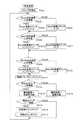
以下、実施の形態を次の順序で説明する。
<1.ヘッドホン装置構成>
<2.第1の実施の形態(FB型ノイズキャンセリングシステム)>
[2−1:信号処理装置構成]
[2−2:装着判定手法]
[2−3:事前測定及び装着判定処理]
<3.第2の実施の形態(FF型ノイズキャンセリングシステム)>
<4.第3の実施の形態(FF+FB型ノイズキャンセリングシステム)>
<5.第4の実施の形態(ノイズキャンセリングシステム非搭載)>
<6.第5の実施の形態>
<7.変形例>
Hereinafter, embodiments will be described in the following order.
<1. Headphone device configuration>
<2. First Embodiment (FB Type Noise Canceling System)>
[2-1: Configuration of signal processing apparatus]
[2-2: Wearing determination method]
[2-3: Prior measurement and wearing determination processing]
<3. Second Embodiment (FF type noise canceling system)>
<4. Third Embodiment (FF + FB type noise canceling system)>
<5. Fourth Embodiment (Noise Canceling System Not Installed)>
<6. Fifth embodiment>
<7. Modification>
<1.ヘッドホン装置構成>
図1は実施の形態のヘッドホン1の概略構成を模式的に示している。
実施の形態のヘッドホン1は、例えばオーバーヘッド密閉型のステレオヘッドホン装置とされ、ユーザの左右の耳の部分にそれぞれ装着される左ハウジング2L、右ハウジング2Rを有する。
左ハウジング2L内には音響出力を行うドライバユニット3L、右ハウジング2R内には音響出力を行うドライバユニット3Rがそれぞれ設けられ、ドライバユニット3L、3Rによりステレオ音響出力を行う。<1. Headphone device configuration>
FIG. 1 schematically shows a schematic configuration of a
The
A
また実施の形態のヘッドホン1では、左ハウジング2Lにおいて、収音孔が筐体外部に向けられて配置された外側マイクロホン4Lと、左ハウジング2Lの内部で収音を行う内側マイクロホン5Lが設けられている。
同様に右ハウジング2R側も、収音孔が筐体外部に向けられて配置された外側マイクロホン4Rと、右ハウジング2Rの内部で収音を行う内側マイクロホン5Rが設けられている。
ユーザがヘッドホン1を装着した状態では、左右ハウジング2L、2Rの内部空間、つまりドライバユニット3L、3Rの放音空間は、ハウジング筐体とユーザの頭部により、外部空間に対し略密閉空間となる。
このため、内側マイクロホン5L、5Rは、使用者に装着された状態で外来音が遮蔽物(ハウジング2L、2R)を介して収音される位置に取り付けられることになる。
一方、外側マイクロホン4L、4Rは、使用者に装着された状態で、外来音が遮蔽物を介さないで収音される位置に取り付けられることになる。In the
Similarly, the
When the user wears the
For this reason, the
On the other hand, the
またヘッドホン1は、いわゆるアクティブヘッドホンであり、信号処理装置6を有する。後述するが信号処理装置6は、音声信号処理等を行う回路部が形成された基板や動作電源としてのバッテリーなどを有する。
具体的には基板やバッテリーは、ハウジング2L又は2R内に収納されたり、或いは再生装置等と接続するコードの途中に筐体が設けられて収納されたりする。The
Specifically, the substrate and the battery are housed in the
ヘッドホン1で例えば音楽等を聴取する場合、ユーザはヘッドホン1を再生装置100に接続して使用する。再生装置100は、例えば携帯型音楽プレーヤ、据え置き型音楽プレーヤ、携帯電話機、パーソナルコンピュータ、携帯型コンピュータなど、各種考えられる。つまり音声信号を出力する各種機器が想定される。
再生装置100で再生された音声信号は、ヘッドホン1の信号処理装置6に入力され、各種処理が施された後、ドライバユニット3L、3Rからステレオ音声として音響出力される。信号処理装置6では、入力された再生音声信号についてのイコライジング等の音響処理を行ったり、ノイズキャンセリング動作のための処理を行う。For example, when listening to music or the like with the
The audio signal reproduced by the
またヘッドホン1は、特に再生装置100と接続されないで使用されることもある。特に信号処理装置6にノイズキャンセリング動作機能を備える場合、ユーザはヘッドホン1を装着することで外来音を大きく低減した状態を得ることができる。例えば飛行機内、電車内などにおいて静かな環境が欲しいユーザは、単にヘッドホン1を装着して電源オンとし、ノイズキャンセリング動作を実行させるという使用形態もある。
Further, the
<2.第1の実施の形態(FB型ノイズキャンセリングシステム)>
[2−1:信号処理装置構成]
上記図1のヘッドホン1において、主に信号処理装置6の構成を説明する。
第1の実施の形態としては、FB(フィードバック:Feedback)型のノイズキャンセリングシステム搭載の場合の構成例を述べる。<2. First Embodiment (FB Type Noise Canceling System)>
[2-1: Configuration of signal processing apparatus]
The configuration of the signal processing device 6 in the
As the first embodiment, a configuration example in the case of mounting an FB (Feedback) type noise canceling system will be described.
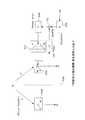
まず図2で第1の実施の形態としての構成例を説明する。
なお、この第1の実施の形態から第6の実施の形態の説明においては、Lチャンネル、Rチャンネルのうち一方のみで図示及び説明を行うが、ステレオ方式のヘッドホンとして、入力される再生音声信号に係る構成やノイズキャンセリング処理のための構成、さらには後述する装着検出のための構成は、他方のチャンネルについても同様である。
また図は一方のチャンネルのみを示すため、図1に示した「3L、3R」のようにL、Rを付した符号ではなく、「ドライバユニット3」「外側マイクロホン4」「内側マイクロホン5」のように「L」「R」を付さずに表記する。First, a configuration example as the first embodiment will be described with reference to FIG.
In the description of the first to sixth embodiments, only one of the L channel and the R channel is shown and described. However, the reproduced audio signal input as stereo headphones is used. The configuration related to the above, the configuration for noise canceling processing, and the configuration for mounting detection described later are the same for the other channel.
In addition, since the figure shows only one channel, it is not a symbol with L and R, such as “3L, 3R” shown in FIG. 1, but “
第1の実施の形態では、信号処理装置6として演算部10、A/D変換器11,12,13、パワーアンプ14、制御部15、電源部16、操作部17、マイクアンプ18,19を備える。
演算部10は、例えばDSP(Digital Signal Processor)などで構成され、音響処理やノイズキャンセリング処理、及び装着検出処理を行う。このため演算部10は、再生音声信号処理部21、ノイズキャンセリング信号処理部22、加算器23、装着状態検出部24、メモリ25としての機能を有するものとされる。In the first embodiment, the signal processing device 6 includes a
The
再生装置100からの再生音声信号(音楽等)は、入力端子7から入力され、A/D変換器11でデジタル信号に変換されて再生音声信号処理部21に入力される。再生音声信号処理部21は、例えば音質補正のためのイコライジング処理や音量処理等を行う。もちろんリバーブ、エコー等の音響効果処理を行うようにしてもよい。
再生音声信号処理部21で処理された再生音声信号は、加算器23を介してパワーアンプ14に供給されて増幅され、ドライバユニット3から音響出力される。A reproduction audio signal (music or the like) from the
The reproduced audio signal processed by the reproduced audio
この第1の実施の形態ではFB型のノイズキャンセリングシステムを搭載する。このため内側マイクロホン5を、ノイズキャンセルのためのマイクロホンとして使用する。
内側マイクロホン5で収音されマイクアンプ18で増幅された音声信号は、A/D変換器13でデジタル信号とされ、ノイズキャンセリング信号処理部22に供給される。ノイズキャンセリング信号処理部22では、収音された音声信号についてノイズキャンセリング用のデジタルフィルタ処理を行ってノイズキャンセリング信号を生成する。
このノイズキャンセリング信号は加算器23で再生音声信号と加算され、パワーアンプ14を介してドライバユニット3から音響出力される。In the first embodiment, an FB type noise canceling system is mounted. For this reason, the
The sound signal collected by the
The noise canceling signal is added to the reproduced audio signal by the
フィードバック方式のノイズキャンセリングシステムにおいては、ユーザ(ヘッドホン1の装着者)の音楽聴取位置であるところの、ノイズと音声信号の音響再生音とを合成する音響合成位置でのノイズを収音する。つまり通常耳に近い位置であるドライバユニット3の振動板前面である。
したがってノイズ収音用のマイクロホンとしては、内側マイクロホン5を用いれば良いことになる
そして、内側マイクロホン5で収音した外来ノイズの逆相成分を、ノイズキャンセリング信号処理部22のフィルタ処理で生成し、それをノイズキャンセリング信号として音響再生することで、外部からヘッドホンハウジング(2L、2R)内に入ってきたノイズ成分を低減させるものである。In the feedback type noise canceling system, noise is collected at the sound synthesis position where the noise (the person wearing the headphones 1) listens to the music and the sound reproduction sound of the audio signal is synthesized. That is, it is the front surface of the diaphragm of the
Therefore, it is sufficient to use the
また実施の形態のヘッドホン1では、ヘッドホン1がユーザに装着されているか否かの検出が行われる。
このため装着状態検出部24には、外側マイクロホン4で収音されマイクアンプ19で増幅された音声信号がA/D変換器12でデジタル信号に変換されて供給される。また装着状態検出部24には、内側マイクロホン5で収音されマイクアンプ18で増幅された音声信号がA/D変換器13でデジタル信号に変換されて供給される。さらにA/D変換器11でデジタル信号とされた再生音声信号も供給される。
また装着状態検出部24は、メモリ25に記憶されている装着状態基準値、非装着状態基準値を参照できるようにされている。Moreover, in the
For this reason, the audio signal collected by the
The wearing
装着状態検出部24は、外側マイクロホン4で得られる音声信号と内側マイクロホン5で得られる音声信号との信号比較を行う。そしてその信号比較結果と、メモリ25に記憶されて装着状態基準値、非装着状態基準値を用いて装着判定を行う。
装着状態基準値とは、ヘッドホン1がユーザに装着された装着状態において、外来音到来時の外側マイクロホン4で得られる音声信号と内側マイクロホン5で得られる音声信号との信号比較結果の理想値である。これは予め測定されてメモリ25に記憶されている。
非装着状態基準値とは、ヘッドホン1がユーザに装着されていない非装着状態において、外来音到来時の外側マイクロホン4で得られる音声信号と内側マイクロホン5で得られる音声信号との信号比較結果の理想値である。これも予め測定されてメモリ25に記憶されている。
装着状態検出部24は、逐次、外側マイクロホン4で得られる音声信号と内側マイクロホン5で得られる音声信号との信号比較を行い、その信号比較結果が、外側マイクロホン4で得られる音声信号と内側マイクロホン5で得られる音声信号との信号比較を行う。その信号比較結果について、非装着状態基準値、及び装着状態基準値との各類似性判断を行って、装着状態か非装着状態かを検出する。そして装着状態検出部24は装着/非装着の検出結果を示す装着検出信号Sdetを制御部15に出力する。The wearing
The wearing state reference value is an ideal value of a signal comparison result between the sound signal obtained by the
The non-wearing state reference value is a signal comparison result between the sound signal obtained by the
The wearing
制御部15は、例えばマイクロコンピュータで構成され、ヘッドホン1の信号処理装置6の各部に制御信号Scを出力し、所要の制御を行う。
例えば演算部10に対しては、再生音声信号処理部21での各種モードに応じたイコライジング係数の指示、ノイズキャンセリング信号処理部22におけるフィルタ係数の設定やノイズキャンセリング機能のオン/オフ制御などを行う。
なおノイズキャンセリングのためのフィルタ処理としては、外部環境に応じて可変設定される場合もある(ノイズキャンセリングモード)。例えば電車内、飛行機内、屋外など、ノイズ環境に適したノイズキャンセリング動作が行われるように、フィルタ係数が切り換えられる場合もある。その場合、制御部15はノイズキャンセリングモードに応じたフィルタ係数設定も行う。
また制御部15は電源部16に対して電源オン/オフの制御を行う。The
For example, for the
Note that the filter processing for noise canceling may be variably set according to the external environment (noise canceling mode). For example, the filter coefficient may be switched so that a noise canceling operation suitable for a noise environment such as in a train, in an airplane, or outdoors is performed. In that case, the
Further, the
電源部16は内蔵バッテリーを電源として、各部に動作電源電圧Vddを供給する。電源電圧Vddの供給のオン/オフ(つまりヘッドホン1の電源オン/オフ)は制御部15からの指示に基づいて行われる。
操作部17として、ユーザが用いる操作子が設けられる。例えば電源ボタン、モードボタン(音響モードやノイズキャンセリングモードの操作子)などが設けられる。
制御部15は、電源ボタンの操作に応じて電源部16に電源オン/オフを指示する。また制御部15は、モードボタンの操作に応じて演算部10の処理モードを指示する。The
As the
The
なお、実施の形態のヘッドホン1は、再生装置100に有線接続されるタイプでもよいし、無線接続されるタイプでもよい。
無線接続されるタイプの場合、A/D変換器11の前段に受信部が設けられることになる。
Note that the
In the case of a type that is wirelessly connected, a receiving unit is provided in the preceding stage of the A /
[2−2:装着判定手法]
以上の構成のヘッドホン1における装着判定手法について詳述する。
図3はFB型ノイズキャンセリングシステムを搭載した第1の実施の形態において、各部の特性を示したものである。
ヘッドホン1(ハウジング2)はユーザの頭部(耳介部)200に装着される。図示する各特性は以下の通りである。[2-2: Wearing determination method]
The wearing determination method in the
FIG. 3 shows the characteristics of each part in the first embodiment equipped with the FB type noise canceling system.
The headphone 1 (housing 2) is attached to the user's head (auricle) 200. The characteristics shown are as follows.
サウンドフィールド301は、音源Nからの外来ノイズが内側マイクロホン5及び外側マイクロホン4に達する音響経路を示す。なお、図4で述べるが、「F」又は「F’」は音響経路を示し、音響特性を「F0」又は「F1」で示すこととする。
加算器302は、ドライバユニット3からの出力音と外来ノイズ音の空間合成を示す。空間合成された音圧(ユーザの聴覚に与えられるサウンドプレッシャー)を「P」で示している。
マイク&マイクアンプ303は、内側マイクロホン5及びマイクアンプ18の収音音声信号経路を示す。マイク&マイクアンプ303の音声信号特性を「M」とする。
NCフィルタ304FBは、演算部10におけるノイズキャンセリング信号処理部22のノイズキャンセリング信号生成用フィルタ処理を示している。このフィルタ処理特性を「−β」とする。
イコライザ305は、演算部10における再生音声信号処理部21で行われるイコライジング処理を示している。この処理特性を「E」とする。なお、入力される再生音声信号を「S」とする。
パワーアンプ306は、パワーアンプ14での増幅処理を示しており、その特性を「A」とする。
ドライバ&アコースティック307は、ドライバユニット3及び放音空間としての出力音声経路を示している。その音響特性を「H」とする。A
The
A microphone &
The NC filter 304FB indicates the noise canceling signal generation filter processing of the noise canceling
An
The
A driver & acoustic 307 indicates the
以上の特性を前提として、まず、再生装置100からの再生音声信号(S)の入力がない場合において、内側マイクロホン5及び外側マイクロホン4で得られる音声信号について、図4で説明する。
図4において、点線500より左側はハウジング2の外部の音声信号系、右側はハウジング2の内部側の音声信号系となるが、この場合、点線500より右側は図3のようなFB型ノイズキャンセリングシステムの要素となり、点線500より左側はノイズキャンセリングシステムの要素とはならない。Based on the above characteristics, the audio signals obtained by the
4, the left side from the dotted
ここでサウンドフィールド301として音響経路F、音響経路F’を示している。
音響経路Fは音源N(外部ノイズ音源)から外側マイクロホン4までの音響経路名、音響経路F’は、音源Nから内側マイクロホン5までの音響経路名とする。Here, an acoustic path F and an acoustic path F ′ are shown as the
The acoustic path F is an acoustic path name from the sound source N (external noise sound source) to the
ここでは、内側マイクロホン5と外側マイクロホン4については、特性が同じものを使用したケースを考える。
マイク&マイクアンプ303は上述のように内側マイクロホン5及びマイクアンプ18の収音音声信号経路であり、マイク&マイクアンプ308は、外側マイクロホン4及びマイクアンプ19の収音音声信号経路である。いずれも特性を「M」とする。
「P」は上述のようにユーザの聴覚に与えられるサウンドプレッシャー(音圧)であるが、これは図4に示すように内側マイクロホン5が収音した音圧となる。
「R」は外側マイクロホン4が収音した音圧とする。Here, consider a case where the
As described above, the microphone &
“P” is the sound pressure (sound pressure) applied to the user's hearing as described above, and this is the sound pressure collected by the
“R” is the sound pressure picked up by the
音源Nから内側マイクロホン5、外側マイクロホン4までの特性は2種類存在する。
遮蔽物が存在しない場合の特性を「F0」、遮蔽物が存在する(ヘッドホンが装着されている)場合の特性を「F1」とする。
つまり、外来音の音源Nから外側マイクロホン4への音響経路Fの特性は常に「F0」である。一方、外来音の音源Nから内側マイクロホン5への音響経路F’の特性は「F0」となる場合(非装着状態)と、「F1」となる場合(装着状態)がある。
ドライバ&アコースティック307の特性「H」も同じく、非装着状態は「H0」、装着状態を「H1」とする。
この特性「F0」「F1」「H0」「H1」は、あらかじめ測定しておくことにより、それぞれひとつの特性を得ておくことができる。There are two types of characteristics from the sound source N to the
The characteristic when the shielding object is not present is “F0”, and the characteristic when the shielding object is present (headphones are attached) is “F1”.
In other words, the characteristic of the acoustic path F from the external sound source N to the
Similarly, the characteristic “H” of the driver & acoustic 307 is “H0” in the non-mounted state and “H1” in the mounted state.
Each of these characteristics “F0”, “F1”, “H0”, and “H1” can be obtained in advance by measuring them in advance.
ここで式1から式7を参照する。
図4の状態で内側マイクロホン5で収音した結果としての音圧Pは、式1で表される。なお、この式1での「F’」は、特性「F0」又は「F1」のいずれかという意味で、便宜的に音響経路名で示している。またドライバ&アコースティック307の特性「H」は、「H0」又は「H1」のいずれかである。
式2は式1を変形したものである。The sound pressure P as a result of sound collection by the
ここで非装着状態、装着状態のそれぞれについて考えると、式3、式4が得られる。
非装着状態ではサウンドフィールド301の特性は「F0」であり、ドライバ&アコースティック307の特性「H0」であるため、式2から式3が得られる。式3は、非装着状態の内側マイクロホン5の収音音圧特性「Q0」を示すものとなる。
装着状態ではサウンドフィールド301の特性は「F1」であり、ドライバ&アコースティック307の特性「H1」であるため、式2から式4が得られる。式4は、装着状態の内側マイクロホン5の収音音圧「Q1」を示すものとなる。Here, considering each of the non-wearing state and the wearing state,
Since the characteristic of the
Since the characteristic of the
一方、外側マイクロホン4で収音した結果の音圧Rは式5となる。サウンドフィールド301の特性は常に「F0」であり、またノイズキャンセリングシステムとは無関係のためである。
この各マイクロホン4、5で得られる音圧(「R」「Q」)の比を計算した場合、非装着状態の理想が式6、装着状態の理想が式7となり、これらは定数となっている。On the other hand, the sound pressure R as a result of sound collection by the
When the ratio of sound pressures (“R” and “Q”) obtained by the
以上の式6,式7としての定数を用いることで、ヘッドホン1の使用時等に、装着検出を行うことができる。
式6の(Q0/R)=1の値が、上述した非装着状態基準値となる。
式7の(Q1/R)=(F1/F0)の値が、上述した装着状態基準値となる。
これらの値はメモリ25に予め行った測定に基づいて保存されているものとする。By using the constants as
The value of (Q0 / R) = 1 in Equation 6 is the above-described non-wearing state reference value.
The value of (Q1 / R) = (F1 / F0) in
These values are stored in the
ヘッドホン1の動作中は、以下の動作を行う。式8〜式11を参照する。
ヘッドホン1の動作中は、内側マイクロホン5で収音した信号「P」、外側マイクロホン4で収音した信号「R」から、常時、式8、式9の「T0」「T1」を計算する。 During the operation of the
式8の算出値T0は、非装着状態を仮定した場合の、外側マイクロホン4で得られる音声信号と内側マイクロホン5で得られる音声信号との信号比較結果の値となる。
実際に非装着状態であったとすると、式8の算出値T0は、理想通りであれば式6の非装着状態基準値(=1)と等しくなる。
また式9の算出値T1は、装着状態を仮定した場合の、外側マイクロホン4で得られる音声信号と内側マイクロホン5で得られる音声信号との信号比較結果の値となる。
実際に装着状態であったとすると、式9の算出値T1は、理想通りであれば式7の装着状態基準値(=F1/F0)と等しくなる。The calculated value T0 of Expression 8 is a value of a signal comparison result between the sound signal obtained by the
If it is actually in a non-wearing state, the calculated value T0 of Equation 8 is equal to the non-wearing state reference value (= 1) of Equation 6 if ideal.
Further, the calculated value T1 of Equation 9 is a value of a signal comparison result between the audio signal obtained by the
If it is actually in the wearing state, the calculated value T1 of Equation 9 is equal to the wearing state reference value (= F1 / F0) of
そこで式8、式9の算出値「T0」「T1」について、理想値との距離を求める。
式10の距離d0は、式8の算出値「T0」と非装着状態基準値(=1)の距離を示す。
式11の距離d1は、式9の算出値「T1」と装着状態基準値(=F1/F0)の距離を示す。
そして、この距離d0、d1を比較する。
もし、d0<d1であれば、非装着状態と判断する。d0≧d1であれば、装着状態と判断する。
d0<d1の場合とは、非装着状態と仮定しての外側マイクロホン4で得られる音声信号と内側マイクロホン5で得られる音声信号との信号比較結果と非装着状態基準値の類似性が、装着状態と仮定しての外側マイクロホン4で得られる音声信号と内側マイクロホン5で得られる音声信号との信号比較結果と装着状態基準値の類似性よりも高いといえるため非装着状態と判定できる。d0≧d1の場合はその逆である。
つまり現在(装着判定処理時)において、外側マイクロホン4で得られる音声信号と内側マイクロホン5で得られる音声信号との信号比較結果について、非装着状態基準値、装着状態基準値との類似性(距離)を判断することで、装着/非装着を判定できる。Therefore, the distance between the calculated values “T0” and “T1” in Equations 8 and 9 and the ideal value is obtained.
The distance d0 in
The distance d1 in
Then, the distances d0 and d1 are compared.
If d0 <d1, it is determined that it is not attached. If d0 ≧ d1, it is determined that the wearing state.
In the case of d0 <d1, the similarity between the signal comparison result between the audio signal obtained by the
That is, at the present time (at the time of wearing determination processing), the similarity (distance) between the non-wearing state reference value and the wearing state reference value for the signal comparison result between the sound signal obtained by the
ここまでは、入力端子7への再生音声信号の入力がない場合で述べたが、再生音声信号(S)の入力を考慮すると、図4は図5のようになる。
つまり再生音声信号(S)についてイコライザ305での信号処理特性「E」が与えられ、これが加算器23でノイズキャンセリング信号(NCフィルタ304FBの出力)と加算される。
すると、上記同様の考え方で各式は以下のようになる。Up to this point, the case where there is no input of the reproduced audio signal to the
That is, the signal processing characteristic “E” in the
Then, with the same idea as above, each formula is as follows.
式12は、内側マイクロホン5が収音する音圧Pの式である。
式13は、式12を、ノイズ音源Nの項と再生音声Sの項に変形したものである。
この式12,式13では、上述の式1,式2と同じく、「F’」は特性「F0」又は「F1」のいずれか、「H」は、「H0」又は「H1」のいずれかである。
式14のP0の式は、式13を、非装着状態と仮定して「F’」=「F0」、「H」=「H0」として変形したものである。
式15のP1の式は、式13を、装着状態と仮定して「F’」=「F1」、「H」=「H1」として変形したものである。
式16は、式14を変形して、非装着状態での内側マイクロホン5の収音音圧特性「Q0」を示すものである。
式17は、式15を変形して、装着状態での内側マイクロホン5の収音音圧特性「Q1」を示すものである。
In
The expression P0 in
The expression P1 in
一方、外側マイクロホン4が収音する音圧Rは式18となる。
この各マイクロホン4、5で得られる音圧(「R」「Q」)の比を計算した場合、非装着状態の理想が式19、装着状態の理想が式20となる。これらは定数となっており、上述の式6、式7と等しい。
従って式19,式20としての定数を用いることで、ヘッドホン1の使用時等に、装着検出を行うことができる。
式19の(Q0/R)=1の値が非装着状態基準値となり、式20の(Q1/R)=(F1/F0)の値が装着状態基準値となる。
これらの値はメモリ25に予め行った測定に基づいて保存されているものとする。On the other hand, the sound pressure R collected by the
When the ratio of the sound pressures (“R” and “Q”) obtained by the
Therefore, by using the constants as
The value of (Q0 / R) = 1 in
These values are stored in the
ヘッドホン1の動作中は、以下の動作を行う。式21〜式24を参照する。
ヘッドホン1の動作中は、内側マイクロホン5で収音した信号「P」、外側マイクロホン4で収音した信号「R」から、常時、式21、式22の「T0」「T1」を計算する。 During the operation of the
式21の算出値T0は、非装着状態を仮定した場合の、外側マイクロホン4で得られる音声信号と内側マイクロホン5で得られる音声信号との信号比較結果の値となる。
実際に非装着状態であったとすると、式21の算出値T0は、理想通りであれば式19の非装着状態基準値(=1)と等しくなる。
また式22の算出値T1は、装着状態を仮定した場合の、外側マイクロホン4で得られる音声信号と内側マイクロホン5で得られる音声信号との信号比較結果の値となる。
実際に装着状態であったとすると、式22の算出値T1は、理想通りであれば式20の装着状態基準値(=F1/F0)と等しくなる。
そこで式21、式22の算出値「T0」「T1」について、式23,式24のように理想値との距離d0、d1を求める。
式23の距離d0は、式21の算出値「T0」と非装着状態基準値(=1)の距離を示す。
式24の距離d1は、式22の算出値「T1」と装着状態基準値(=F1/F0)の距離を示す。そして、この距離d0、d1を比較する。
もし、d0<d1であれば、非装着状態と判断する。d0≧d1であれば、装着状態と判断する。
つまり現在(装着判定処理時)において、外側マイクロホン4で得られる音声信号と内側マイクロホン5で得られる音声信号との信号比較結果について、非装着状態基準値、装着状態基準値との類似性(距離)を判断することで、装着/非装着を判定できる。The calculated value T0 of
If it is actually in a non-wearing state, the calculated value T0 of
Further, the calculated value T1 of
If it is actually in the wearing state, the calculated value T1 of
Therefore, the calculated distances “T0” and “T1” of
The distance d0 in
The distance d1 in
If d0 <d1, it is determined that it is not attached. If d0 ≧ d1, it is determined that the wearing state.
That is, at the present time (at the time of wearing determination processing), the similarity (distance) between the non-wearing state reference value and the wearing state reference value for the signal comparison result between the sound signal obtained by the
このように、音楽等の再生音声をヘッドホン1で音響出力している場合でも、結局は再生音声がない場合と同様に、装着状態検出を行うことができることが理解される。
実際のヘッドホン1では、上記式12〜式24で述べた考え方で装着状態検出を行うようにすれば良い。即ちヘッドホン動作中はリアルタイム処理として式21、式22の算出を行うようにすれば良い。式21、式22において、再生音声信号Sの入力がない場合には、これらは式8、式9と等しくなるため、再生音声信号の入力の有無を判定する必要はなく、常に式21、式22の計算をすればよいことがわかる。As described above, it is understood that even when the reproduced sound such as music is acoustically output from the
In the
但し、リアルタイム処理として、再生装置100からの再生音声信号入力の有無を検出して、式21、式22の算出を行う場合と、式8、式9の算出を行う場合とを切り換えるようにしてもよい。 However, as real-time processing, the presence / absence of a playback audio signal input from the
また最終的に式23,式24で得られた距離d0、d1の比較を行う場合に、係数を用いて(d0・k0)と(d1・k1)の比較を行うようにしてもよい。
係数k0、k1の設定によっては、「なるべく非装着と判定されやすくする」或いは「なるべく非装着と判定されにくくする」などの調整が可能となる。
例えば後述するが、判定結果として非装着状態と検出した際に、制御部15が電源オフ制御を行うこととする場合、使用状況に適した電源オフ制御が行われる必要がある。
ヘッドホン1の装着状態の個人差や、外部ノイズ状況などによっては、ユーザが装着して使用しているのに非装着と誤判定されやすいことがあり得る。そして例えば音楽鑑賞中、或いはノイズキャンセル中(耳栓としての使用中)などに、たびたび非装着と誤検出されて電源オフとされてしまうことは好ましくない。そのようなことを考慮すれば、係数設定により、なるべく非装着と判定されにくくすることが適切である。
逆に誤判定の恐れがあまりないのであれば、非装着状態でのバッテリー消耗を避けるという考え方から、係数設定によりなるべく非装着と判定されやすくするということも考えられる。
Further, when comparing the distances d0 and d1 finally obtained by
Depending on the settings of the coefficients k0 and k1, adjustments such as “easy to be determined as non-wearing as much as possible” or “as difficult to be determined as non-wearing as much as possible” are possible.
For example, as described later, when the
Depending on individual differences in the wearing state of the
On the other hand, if there is not much fear of erroneous determination, it can be considered that the determination of non-installation is made as easy as possible by setting the coefficient from the idea of avoiding battery consumption in the non-installation state.
[2−3:事前測定及び装着判定処理]
以下では、上記の考え方に基づく装着判定の具体的な処理について説明していく。
まず、予め記憶しておくことが必要となる装着状態基準値Q1/R(=F1/F0)と非装着状態基準値Q0/R(=1)について説明する。[2-3: Prior measurement and wearing determination processing]
Below, the specific process of mounting | wearing determination based on said view is demonstrated.
First, the wearing state reference value Q1 / R (= F1 / F0) and the non-wearing state reference value Q0 / R (= 1) that need to be stored in advance will be described.
実際にヘッドホン1において上述の考え方で装着判定を行うようにする場合、理想的な装着状態と理想的な非装着状態を規定して、その環境であらかじめ測定を行って、ノイズキャンセリング方式に対応した基準となる式(式19、式20)により、非装着状態基準値と装着状態基準値を求める。 When actually using the
図6に予め行う測定の様子を示す。図6Aは非装着状態、図6Bは装着状態での測定を示している。
測定の際にはスピーカなどの音源110を正中線に置いてホワイトノイズ(あるいはピンクノイズや、擬似騒音信号)を発生させる。
図6Bの装着状態での測定の場合は、理想的な装着状態として、例えば定めたダミーヘッドで測定を行う。もしくは複数人に装着させて測定を行って、その特性の平均を用いることが考えられる。FIG. 6 shows a state of measurement performed in advance. FIG. 6A shows the measurement in the non-wearing state, and FIG. 6B shows the measurement in the wearing state.
In measurement, a
In the case of measurement in the mounted state of FIG. 6B, as an ideal mounted state, for example, measurement is performed with a predetermined dummy head. Alternatively, it is conceivable that a plurality of people wear the measurement and use the average of the characteristics.
図7Aは、非装着状態基準値Q0/R(=1)としての周波数特性と、装着状態基準値Q1/R(=F1/F0)としての周波数特性を示している。
例えばこの図のような周波数特性測定を行い、周波数特性測定結果を非装着状態基準値、装着状態基準値とする。FIG. 7A shows the frequency characteristic as the non-wearing state reference value Q0 / R (= 1) and the frequency characteristic as the wearing state reference value Q1 / R (= F1 / F0).
For example, the frequency characteristic measurement as shown in this figure is performed, and the frequency characteristic measurement result is set as the non-wearing state reference value and the wearing state reference value.
図8は、このような事前測定を行うための装着状態検出部24の処理例を示している。
制御部15は演算部10における装着状態検出部24に対し、制御信号Scにより、非装着状態基準値、装着状態基準値としての各基準特性算出動作の実行を指示する。
この場合、装着状態検出部24は、FFT(Fast Fourier Transform)処理401,402、及び基準特性算出処理403を行うこととなる。FIG. 8 shows a processing example of the wearing
The
In this case, the wearing
まず図6Aの非装着状態での測定において、装着状態検出部24は、外側マイクロホン4で収音され、マイクアンプ19,A/D変換器12を介して入力される音声信号に対し、FFT処理401を行う。また装着状態検出部24は、内側マイクロホン5で収音され、マイクアンプ18,A/D変換器13を介して入力される音声信号に対し、FFT処理402を行う。
そして装着状態検出部24は、FFT処理401,402の結果に対し、基準特性算出処理403を行う。FFT処理401の結果とは、上述の音圧Rについての周波数特性であり、FFT処理402の結果とは、音圧Pについての周波数特性である。
基準特性算出処理403では、上記「P」「R」についての周波数特性の振幅比較を行なう。それは結局、図6Aの非装着状態での測定時には図7Aのようになり、これが式19で示した非装着状態基準値(=1)となる。また図6Bの装着状態での測定時には図7Bのようになり、これが式20で示した装着状態基準値(=F1/F2)となる。
装着状態検出部24は、これらをメモリ25に記憶させる。First, in the measurement in the non-wearing state of FIG. 6A, the wearing
Then, the wearing
In the reference
The wearing
このような事前記憶を行った上で、実際の使用時に装着判定を行う。
図9は装着判定時の処理を示している。装着状態検出部24は、FFT処理401,402,404、及び装着状態判定処理405を行う。
ヘッドホン使用時は、装着判定を行うために、装着状態検出部24は、外側マイクロホン4で収音され、マイクアンプ19,A/D変換器12を介して入力される音声信号に対し、FFT処理401を行う。また装着状態検出部24は、内側マイクロホン5で収音され、マイクアンプ18,A/D変換器13を介して入力される音声信号に対し、FFT処理402を行う。さらに入力端子7に入力され、A/D変換器11を介した再生音声信号についてもFFT処理404を行う。
FFT処理401の結果は上述の「R」の周波数特性である。FFT処理402の結果は上述の「P」の周波数特性である。FFT処理404の結果は上述の「S」の周波数特性である。
装着状態判定処理405では、この結果を(「P」「R」「S」の周波数特性)を用いて、上述の式21,式22の演算を行う。
そして、式21,式22で得られた算出値T0、T1と、メモリ25から読み出した非装着状態基準値、装着状態基準値を用いて装着判定を行う。つまり式23,式24で距離d0、d1 を求め、その比較結果で装着状態/非装着状態の判定を行う。After performing such pre-storage, the wearing determination is performed during actual use.
FIG. 9 shows processing at the time of wearing determination. The wearing
When using headphones, the wearing
The result of the
In the wearing
Then, the wearing determination is performed using the calculated values T0 and T1 obtained by the
即ち、実際の動作中は一定間隔でリアルタイムに内側マイクロホン5の収音信号(P)と外側マイクロホン4の収音信号(R)の周波数解析を行って振幅の比較をする。そして、その結果が事前測定結果の装着状態基準値の周波数特性と、非装着状態基準値の周波数特性のどちらに近いかを判別することとなる。図7Bに、算出値T0と非装着状態基準値の比較、及び算出値T1と装着状態基準値の比較を示している。これらの比較により距離d0、d1 を求める。
実際の比較方法としては、たとえば図7Bの非装着状態想定、装着状態想定について、それぞれ周波数軸上での振幅差の面積を算出して比較する。即ちT0周波数特性カーブと、非装着状態基準値の周波数特性(全帯域で1)の差分面積と、T1周波数特性カーブと、装着状態基準値のF1/F2周波数特性カーブの差分面積を比較する。
あるいは特徴的な周波数に着目してその振幅差(あるいは比)の総計や平均を算出して比較してもよい。
また、たとえば図7Bのような周波数軸上での振幅差の面積を算出して閾値と比較したり、あるいは特徴的な周波数に着目してその振幅差(あるいは比)の総計や平均を算出して閾値と比較することなども考えられる。That is, during an actual operation, the amplitude is compared by performing frequency analysis of the collected sound signal (P) of the
As an actual comparison method, for example, for the non-wearing state assumption and the wearing state assumption of FIG. 7B, the areas of the amplitude differences on the frequency axis are calculated and compared. That is, the difference area between the T0 frequency characteristic curve and the frequency characteristic of the non-wearing state reference value (1 in all bands), the difference between the T1 frequency characteristic curve and the F1 / F2 frequency characteristic curve of the wearing state reference value are compared.
Alternatively, the total or average of the amplitude differences (or ratios) may be calculated and compared by paying attention to the characteristic frequency.
Further, for example, the area of the amplitude difference on the frequency axis as shown in FIG. 7B is calculated and compared with the threshold value, or the total or average of the amplitude difference (or ratio) is calculated by paying attention to the characteristic frequency. It is also possible to compare with a threshold value.
装着状態検出部24は、以上の処理で得られた判定結果について、これを即時に最終結果として制御部15に通知することも可能ではある。但し、例えば非装着状態では電源消し忘れと認識して自動的に電源をオフにする等の処理を行う場合装着、装着検出の確実性を得るためにサンプル数を多くしたり、非装着状態判定が規定した連続回数に達する、あるいは規定した割合に達する場合に最終結果を非装着状態とするなどが考えられる。
そこで装着状態検出部24は、図10Aのような処理を行うようにするとよい。The wearing
Therefore, the wearing
図10Aは装着状態検出部24の装着状態判定処理405としての処理例を示している。
装着状態検出部24は、ステップF101でカウンタ初期化を行う。例えば周期カウンタ、非装着カウンタを初期化する。周期カウンタは、一定の検出単位期間としての一周期をカウントするカウンタであり、非装着カウンタは、非装着状態と検出される状態の継続時間をカウントするカウンタである。FIG. 10A shows a processing example as the mounting state determination processing 405 of the mounting
The wearing
装着状態検出部24はステップF102で、上記手法により装着/非装着の判定を行う。そして非装着状態と判定した場合は、ステップF103で非装着カウンタをインクリメントする。一方、装着状態と判定した場合はステップF104で非装着カウンタをクリアする。 In step F102, the mounting
装着状態検出部24はステップF105では、非装着カウンタの値が所定の閾値を越えているか否かを確認する。
上記のステップF103,F104の処理からわかるように、非装着カウンタは、ステップF102で「非装着」と判定される状態の継続時間を示すカウンタである。装着状態検出部24は「非装着」と判定されている状態が、閾値としての所定時間を越えたら、ステップF106で最終結果として「非装着」とし、非装着状態を検出信号Sdetにより制御部15に通知する。
一方、非装着カウンタの値が所定の閾値に達していなければ、ステップF107で最終結果として「装着」とし、装着状態を検出信号Sdetで制御部15に通知する。In step F105, the wearing
As can be seen from the processing in steps F103 and F104, the non-wearing counter is a counter indicating the duration of the state determined as “non-wearing” in step F102. When the state determined to be “non-wearing” exceeds a predetermined time as a threshold, the wearing
On the other hand, if the value of the non-wearing counter does not reach the predetermined threshold, the final result is “wearing” in step F107, and the wearing state is notified to the
装着状態検出部24はステップF108では周期カウンタをインクリメントする。
そしてステップF109で周期カウンタの値が所定の一周期としてのカウンタ値を越えたか否かを確認する。越えていなければ、ステップF102の処理をそのまま継続する。一周期に達していたら、装着状態検出部24はステップF110で周期カウンタをクリアし、またステップF111で非装着カウンタをクリアしてステップF102に戻る。The wearing
In step F109, it is confirmed whether or not the value of the cycle counter has exceeded the counter value as a predetermined cycle. If not, the process in step F102 is continued as it is. If one cycle has been reached, the mounting
装着状態検出部24は、以上の処理を、例えば電源オン中は継続して実行する。これにより、周期カウンタで計測される周期単位で、非装着判定状態が所定時間以上継続した場合に、「非装着」としての検出結果が制御部15に通知される。 The wearing
一方制御部15は、例えば図10Bの処理を行う。
例えば所定時間毎の割り込み処理等で、ステップF201で検出信号Sdetのチェックを行う。検出信号Sdetが「非装着」を示す値であった場合は、制御部15は処理をステップF202からF203に進め、電源部16に対して電源オフ制御を行う。
このような処理により、装着状態検出部24が非装着状態を検出することに応じて、ヘッドホン1の電源オフが実行される。例えばユーザがヘッドホン1を外すことで、自動的に電源オフとなり、無用なバッテリー消費が避けられる。On the other hand, the
For example, the detection signal Sdet is checked in step F201 by interrupt processing at predetermined intervals. If the detection signal Sdet is a value indicating “non-wearing”, the
By such processing, the
以上のように装着状態検出部24は、周期単位内での非装着状態の判定の継続性をもって、最終的に「非装着」と判定されるようにすることで、非装着状態を確実性をもって検出できることになる。上記のように非装着検出に応じて制御部15が電源オフ制御を行う場合、ヘッドホン使用時に非装着状態と誤判定すると、ユーザにとって予期せずに電源オフとなることになり不都合である。そこで、図10Aの処理で、非装着状態を確実に検出できるようにし、非装着であることの誤検出がないようにすることが実用上好適となる。 As described above, the wearing
なお図10Aの処理に代えて装着状態検出部24は図11の処理を行うようにしてもよい。
図11の処理が図10Aの処理と異なるのはステップF104を行わない点である。即ちステップF102で非装着ではないと判定した際には、非装着カウンタをクリアせずにステップF105に進む。他の処理は図10Aと同様である。
この場合、ステップF102で一時的に装着状態と判定されても非装着カウンタはクリアされないため、ステップF105で閾値と比較する非装着カウンタの値は、非装着判定の継続時間ではなく、周期単位内での累積時間(非装着判定回数)となる。
つまり周期単位内で、非装着と判定される割合が高ければ、最終結果としてステップF106で非装着と検出されることになる。
この処理でも図10Aと同様に、非装着判定の確実性を高めることができる。Note that the mounting
The process of FIG. 11 differs from the process of FIG. 10A in that step F104 is not performed. That is, when it is determined in step F102 that it is not non-attached, the process advances to step F105 without clearing the non-attachment counter. Other processes are the same as those in FIG. 10A.
In this case, since the non-wearing counter is not cleared even if it is temporarily determined to be in the wearing state in Step F102, the value of the non-wearing counter to be compared with the threshold value in Step F105 is not the duration of the non-wearing judgment but within the period unit. This is the accumulated time (number of non-wearing determinations).
That is, if the ratio determined to be non-wearing is high within the cycle unit, the non-wearing is detected in step F106 as the final result.
Even in this process, as in FIG. 10A, the certainty of the non-wearing determination can be improved.
以上、第1の実施の形態について説明してきたが、実施の形態のヘッドホン1では、外側マイクロホン4、内側マイクロホン5で収音された音声信号を用いて装着/非装着を検出する。
非装着状態が検出された場合に電源オフ制御を行うようにすることで、いわゆる電源消し忘れを防ぎ、バッテリーの無駄な消費を防止できる。これによってアクティブヘッドホンにおいて意図しない電池消耗による不都合を解消できる。As described above, the first embodiment has been described. In the
By performing power-off control when a non-mounted state is detected, so-called forgetting to turn off the power can be prevented, and useless consumption of the battery can be prevented. This eliminates inconvenience caused by unintended battery consumption in the active headphones.
さらにその上で本実施の形態の場合、再生装置100からの音楽等の再生音声を出力していない場合でも装着/非装着の検出が可能である。従ってノイズキャンセリングシステムを利用した、静寂を得るための使用の際にも適切に装着状態検出を行い、これに応じた電源制御を行うことができる。
また本実施の形態の場合、装着検出に必要な内側マイクロホン5はFB型ノイズキャンセリングシステムのために搭載するマイクロホンを共用できる。このため構成素子としては外側マイクロホン4を追加するのみで、部品的な負担は小さい。また外側マイクロホン4として小型のマイクロホンを追加することは、デザイン上の制約や、ヘッドホンサイズの大型化等も殆ど生じない。このため密閉型ヘッドホンだけでなく、インナーイヤータイプ、カナルタイプなどのヘッドホン(イヤホン)での適用にも適している。
またユーザの装着感に影響を与えることもない。
In addition, in the case of the present embodiment, it is possible to detect the attachment / non-attachment even when the reproduction sound such as music from the
In the case of this embodiment, the
In addition, the user's wearing feeling is not affected.
<3.第2の実施の形態(FF型ノイズキャンセリングシステム)>
第2の実施の形態として、FF(フィードフォワード:Feedforward)型のノイズキャンセリングシステム搭載の場合について説明する。
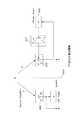
図12は、図2と同様の形式で第1の実施の形態におけるFF型ノイズキャンセリングシステム搭載のヘッドホン1の構成例を示している。なお図2と同一部分には同一符号を付し、説明を省略する。
この図12において図2と異なるのは、外側マイクロホン4で収音された音声信号が、マイクアンプ19,A/D変換器12を介してノイズキャンセリング信号処理部22に供給される点である。他は図2と同様となる。<3. Second Embodiment (FF type noise canceling system)>
As a second embodiment, a case where a FF (Feedforward) type noise canceling system is installed will be described.
FIG. 12 shows a configuration example of the
12 is different from FIG. 2 in that the sound signal collected by the
FF方式のノイズキャンセルシステムは、基本的には、ヘッドホン筐体外部にノイズ収音用のマイクロホン(外側マイクロホン4)を設置し、その外側マイクロホン4で収音したノイズに対して適切なフィルタリング処理をしてノイズキャンセリング信号を生成する。この生成したノイズキャンセリング信号を、ドライバユニット3にて音響再生し、リスナの耳に近いところ、つまりドライバユニット3の振動板前面でノイズをキャンセルする。
外側マイクロホン4で収音されるノイズと、ヘッドホン筐体内のノイズは、両者の空間的位置の違い(ヘッドホンハウジング2の外と内の違いを含む)に応じた異なる特性となる。したがって、フィードフォワード方式の場合、ノイズキャンセリング信号処理部22では、外側マイクロホン4で収音したノイズと、ノイズキャンセルポイント(ドライバユニット前面のリスナの聴取ポイント)におけるノイズとの空間伝達関数の違いを見込んで、ノイズキャンセリング信号を生成するようにする。The FF type noise cancellation system basically has a noise collecting microphone (outside microphone 4) installed outside the headphone housing, and performs an appropriate filtering process on the noise collected by the
The noise collected by the
装着状態検出部24に対しては、外側マイクロホン4で収音されマイクアンプ19で増幅された音声信号がA/D変換器12でデジタル信号に変換されて供給される。また装着状態検出部24には、内側マイクロホン5で収音されマイクアンプ18で増幅された音声信号がA/D変換器13でデジタル信号に変換されて供給される。さらにA/D変換器11でデジタル信号とされた再生音声信号も供給される。
また装着状態検出部24は、メモリ25に記憶されている装着状態基準値、非装着状態基準値を参照できるようにされている。A sound signal collected by the
The wearing
図13はFF方式のノイズキャンセリングシステムの各部の特性を示している。上述の図3と異なるのは、ノイズキャンセルに用いるのが外側マイクロホン4となる点である。外側マイクロホン4及びマイクアンプ19の特性を、マイク&マイクアンプ308として示し、その音声信号特性を「M」としている。
またNCフィルタ304FFは、演算部10におけるノイズキャンセリング信号処理部22のFF方式でのノイズキャンセリング信号生成用フィルタ処理を示している。このフィルタ処理特性を「α」とする。
他は図3と同様に、サウンドフィールド301(F)、イコライザ305(E)、パワーアンプ306(A)、ドライバ&アコースティック307(H)、外来ノイズの音源N、及び再生音声信号Sを示している。FIG. 13 shows the characteristics of each part of the FF type noise canceling system. The difference from FIG. 3 described above is that the
An NC filter 304FF represents the noise canceling signal generation filter processing in the FF method of the noise canceling
Others are the same as in FIG. 3, showing the sound field 301 (F), equalizer 305 (E), power amplifier 306 (A), driver & acoustic 307 (H), external noise source N, and reproduced audio signal S. Yes.
以上の特性を前提として、まず、再生装置100からの再生音声信号(S)の入力がない場合において、内側マイクロホン5及び外側マイクロホン4で得られる音声信号について、図14で説明する。図4と同様の形式で示すが、この図14の場合、外側マイクロホン4で得られる音声信号がNCフィルタ304FFへ入力される。 Based on the above characteristics, first, audio signals obtained by the
式25から式31を参照する。
非装着状態と仮定する場合、内側マイクロホン5が収音する音圧P(P0とする)は式25で表される。
装着状態と仮定する場合、内側マイクロホン5が収音する音圧P(P1とする)は式26で表される。
外側マイクロホン4が収音した音圧Rは式27で表される。Assuming the non-wearing state, the sound pressure P (P 0) collected by the
Assuming the wearing state, the sound pressure P (referred to as P1) collected by the
The sound pressure R picked up by the
第1の実施の形態と同様に比を算出すると、非装着状態では式28、式30が、また装着状態では式29、式31が得られる。
式30は非装着状態基準値、式31は装着状態基準値を示し、上述の式6、式7と等しい。When the ratio is calculated in the same manner as in the first embodiment, Expressions 28 and 30 are obtained in the non-wearing state, and Expressions 29 and 31 are obtained in the wearing state.
Equation 30 represents the non-wearing state reference value, and Equation 31 represents the wearing state reference value, which is equal to
ヘッドホン1の動作中は、以下の動作を行う。式32〜式35を参照する。
第1の実施の形態と同様に、ヘッドホン1の動作中に内側マイクロホン5と外側マイクロホン4で収音した「P」と「R」から、常に式32、式33の「T0」「T1」を計算する。
式32の「T0」は非装着状態の場合、理想通りであれば式30と等しくなる。式33の「T1」は装着状態の場合、理想通りであれば式31と等しくなる。
よって式32、式33を計算して式34、式35を導き、式30、式31と比較する。
式34の距離d0は、式32の算出値「T0」と非装着状態基準値(=1)の距離を示す。式35の距離d1は、式33の算出値「T1」と装着状態基準値(=F1/F0)の距離を示す。そして、この距離d0、d1を比較する。
もし、d0<d1であれば、非装着状態と判断する。d0≧d1であれば、装着状態と判断する。
このような考え方で装着/非装着を判定できる。As in the first embodiment, “T0” and “T1” in Expressions 32 and 33 are always obtained from “P” and “R” collected by the
“T0” in Expression 32 is equal to Expression 30 in the non-wearing state if it is ideal. “T1” in Expression 33 is equal to Expression 31 in the mounted state if it is ideal.
Therefore, Equations 32 and 33 are calculated to derive Equations 34 and 35, which are compared with Equations 30 and 31.
The distance d0 in Expression 34 indicates the distance between the calculated value “T0” in Expression 32 and the non-wearing state reference value (= 1). The distance d1 in Expression 35 indicates the distance between the calculated value “T1” in Expression 33 and the wearing state reference value (= F1 / F0). Then, the distances d0 and d1 are compared.
If d0 <d1, it is determined that it is not attached. If d0 ≧ d1, it is determined that the wearing state.
Wearing / non-wearing can be determined based on this concept.
図15は再生音声信号(S)の入力を考慮した場合である。
つまり再生音声信号(S)についてイコライザ305での信号処理特性「E」が与えられ、これが加算器23でノイズキャンセリング信号(NCフィルタ304FFの出力)と加算される。
すると、上記同様の考え方で各式は以下のようになる。FIG. 15 shows a case where the input of the reproduced audio signal (S) is considered.
That is, the signal processing characteristic “E” in the
Then, with the same idea as above, each formula is as follows.
式36のP0の式は、非装着状態と仮定した場合の内側マイクロホン5が収音する音圧の式である。式37は、式36を変形して、非装着状態での内側マイクロホン5の収音音圧特性「Q0」を示すものである。
式38のP1の式は、装着状態と仮定した場合の内側マイクロホン5が収音する音圧の式である。式39は、式38を変形して、装着状態での内側マイクロホン5の収音音圧特性「Q1」を示すものである。
外側マイクロホン4が収音する音圧Rは上述の式27となる。The expression P0 in Expression 36 is an expression of the sound pressure collected by the
The expression P1 in Expression 38 is an expression of the sound pressure that the
The sound pressure R collected by the
これまでと同様に比を算出すると、非装着状態では式40、式41、装着状態では式42、式43が得られる。式41、式43は上述の式6、式7と等しい。
従って式41としての非装着状態基準値,式43としての装着状態基準値を用いることで、ヘッドホン1の使用時等に、装着検出を行うことができる。When the ratio is calculated in the same manner as before, Expressions 40 and 41 are obtained in the non-wearing state, and Expressions 42 and 43 are obtained in the wearing state. Expressions 41 and 43 are equal to
Therefore, by using the non-wearing state reference value as Equation 41 and the wearing state reference value as Equation 43, wearing detection can be performed when the
ヘッドホン1の動作中は、以下の動作を行う。式44〜式47を参照する。
ヘッドホン1の動作中は、内側マイクロホン5で収音した信号「P」、外側マイクロホン4で収音した信号「R」から、常時、式44、式45の「T0」「T1」を計算する。
式44の算出値T0は、非装着状態を仮定した場合の、外側マイクロホン4で得られる音声信号と内側マイクロホン5で得られる音声信号との信号比較結果の値となり、実際に非装着状態であったとすると、算出値T0は、理想通りであれば式41の非装着状態基準値(=1)と等しくなる。
また式45の算出値T1は、装着状態を仮定した場合の、外側マイクロホン4で得られる音声信号と内側マイクロホン5で得られる音声信号との信号比較結果の値となり、実際に装着状態であったとすると、算出値T1は、理想通りであれば式43の装着状態基準値(=F1/F0)と等しくなる。During the operation of the
The calculated value T0 in Equation 44 is the value of the signal comparison result between the audio signal obtained by the
Further, the calculated value T1 of Expression 45 is a value of a signal comparison result between the audio signal obtained by the
そこで算出値「T0」「T1」について、式46,式47のように理想値との距離d0、d1を求める。距離d0は、算出値「T0」と非装着状態基準値(=1)の距離を示し、距離d1は、算出値「T1」と装着状態基準値(=F1/F0)の距離を示す。
そして、この距離d0、d1を比較する。もし、d0<d1であれば、非装着状態と判断する。d0≧d1であれば、装着状態と判断する。
このように、外側マイクロホン4で得られる音声信号と内側マイクロホン5で得られる音声信号との信号比較結果について、非装着状態基準値、装着状態基準値との類似性(距離)を判断することで、装着/非装着を判定できる。Therefore, distances d0 and d1 between the calculated values “T0” and “T1” from the ideal values are obtained as in equations 46 and 47. The distance d0 indicates the distance between the calculated value “T0” and the non-wearing state reference value (= 1), and the distance d1 indicates the distance between the calculated value “T1” and the wearing state reference value (= F1 / F0).
Then, the distances d0 and d1 are compared. If d0 <d1, it is determined that it is not attached. If d0 ≧ d1, it is determined that the wearing state.
As described above, the similarity (distance) between the non-wearing state reference value and the wearing state reference value is determined for the signal comparison result between the sound signal obtained by the
以上のように、音楽等の再生音声をヘッドホン1で音響出力している場合でも、結局は再生音声がない場合と同様に、装着状態検出を行うことができる。
実際のヘッドホン1では、上記式36〜式47で述べた考え方で装着状態検出を行うようにすれば良い。即ちヘッドホン動作中はリアルタイム処理として式44、式45の算出を行うようにする。再生音声信号Sの入力がない場合には、式44、式45は式32、式33と等しくなるためである。
また最終的に式46,式47で得られた距離d0、d1の比較を行う場合に、係数を用いて(d0・k0)と(d1・k1)の比較を行うようにしてもよい。As described above, even when the reproduced sound such as music is acoustically output from the
In the
Further, when comparing the distances d0 and d1 finally obtained by the equations 46 and 47, a comparison may be made between (d0 · k0) and (d1 · k1) using a coefficient.
以上、FF方式のノイズキャンセリングシステムを採用したヘッドホン1の場合も、第1の実施の形態と同様の考え方で装着検出を行うことができる。
具体的な動作は第1の実施の形態において図6〜図11で説明した動作と同様とすれば良い。
そして第2の実施の形態でも第1の実施の形態と同様の効果が得られる。なお第2の実施の形態の場合、装着検出に必要な外側マイクロホン4が、FF型ノイズキャンセリングシステムのために搭載するマイクロホンとして共用できることになる。
As described above, even in the case of the
The specific operation may be the same as the operation described in the first embodiment with reference to FIGS.
In the second embodiment, the same effects as in the first embodiment can be obtained. In the case of the second embodiment, the
<4.第3の実施の形態(FF+FB型ノイズキャンセリングシステム)>
第3の実施の形態として、FF型+FB型のノイズキャンセリングシステム(ツイン型とも呼ぶ)を搭載したヘッドホン1を説明する。
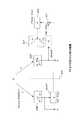
図16は、図2,図12と同様の形式で第3の実施の形態におけるツイン型ノイズキャンセリングシステム搭載のヘッドホン1の構成例を示している。なお図2、図12と同一部分には同一符号を付し、説明を省略する。<4. Third Embodiment (FF + FB type noise canceling system)>
As a third embodiment, a
FIG. 16 shows a configuration example of the
この図16においては、外側マイクロホン4で収音された音声信号がマイクアンプ19,A/D変換器12を介してノイズキャンセリング信号処理部22に供給され、さらに内側マイクロホン5収音された音声信号がマイクアンプ18,A/D変換器13を介してノイズキャンセリング信号処理部22に供給される。
ノイズキャンセリング信号処理部22では、上述のFB方式のデジタルフィルタ処理(−β)と、FF方式のデジタルフィルタ処理(α)を行い、各フィルタ処理出力を合成してノイズキャンセリング信号を生成する。In FIG. 16, the sound signal picked up by the
The noise canceling
他は既述の実施の形態と同様である。
装着状態検出部24に対しては、第1,第2の実施の形態と同様、外側マイクロホン4の収音音声信号、内側マイクロホン5の収音音声信号、及び再生音声信号が供給される。Others are the same as the embodiment described above.
As in the first and second embodiments, the sound collection sound signal of the
図17はツイン方式のノイズキャンセリングシステムの各部の特性を示している。
外側マイクロホン4と内側マイクロホン5の両方がノイズキャンセリングのために利用される。
内側マイクロホン5及びマイクアンプ18の特性を、マイク&マイクアンプ303として示し、その音声信号特性を「M1」としている。
外側マイクロホン4及びマイクアンプ19の特性を、マイク&マイクアンプ308として示し、その音声信号特性を「M2」としている。
またNCフィルタ304FBは、ノイズキャンセリング信号処理部22のFB方式のフィルタ処理を示し、このフィルタ処理特性を「−β」とする。
NCフィルタ304FFは、ノイズキャンセリング信号処理部22のFF方式でのフィルタ処理を示し、このフィルタ処理特性を「α」とする。
他は図3、図13と同様に、サウンドフィールド301(F)、イコライザ305(E)、パワーアンプ306(A)、ドライバ&アコースティック307(H)、外来ノイズの音源N、及び再生音声信号Sを示している。FIG. 17 shows the characteristics of each part of the twin type noise canceling system.
Both the
The characteristics of the
The characteristics of the
An NC filter 304FB indicates the FB filter processing of the noise canceling
The NC filter 304FF represents the FF method filter processing of the noise canceling
Others are the same as in FIGS. 3 and 13, the sound field 301 (F), the equalizer 305 (E), the power amplifier 306 (A), the driver & acoustic 307 (H), the external noise source N, and the reproduced audio signal S. Is shown.
以上の特性を前提として、まず、再生装置100からの再生音声信号(S)の入力がない場合において、内側マイクロホン5及び外側マイクロホン4で得られる音声信号について、図18で説明する。図4、図14と同様の形式で示すが、この図18の場合、外側マイクロホン4で得られる音声信号がNCフィルタ304FFへ入力され、内側マイクロホン5で得られる音声信号がNCフィルタ304FBへ入力される。そしてNCフィルタ304FF、NCフィルタ304FBの出力が加算器23で合成されてパワーアンプ306に供給される。
なおマイク&マイクアンプ303、マイク&マイクアンプ308の特性はMとする(M1=M2)。Based on the above characteristics, first, audio signals obtained by the
The characteristics of the microphone &
式48から式56を参照する。
外側マイクロホン4が収音した音圧Rは式48で表される。
非装着状態と仮定する場合、内側マイクロホン5が収音する音圧P(P0とする)は式49で表される。
式49を変形して式50のQ0が得られる。
第1の実施の形態と同様に比を算出すると、非装着状態では式51、式52が得られる。
式52は非装着状態基準値となり、上述の式6と等しい。The sound pressure R picked up by the
Assuming the non-wearing state, the sound pressure P (P 0) collected by the
Equation 49 is transformed to obtain Q0 of Equation 50.
When the ratio is calculated in the same manner as in the first embodiment, Expression 51 and Expression 52 are obtained in the non-wearing state.
Expression 52 is a non-wearing state reference value, and is equal to Expression 6 described above.
装着状態と仮定する場合、内側マイクロホン5が収音する音圧P(P1とする)は式53で表される。
式53を変形して式54のQ1が得られる。
第1の実施の形態と同様に比を算出すると、装着状態では式55、式56が得られる。
式56は装着状態基準値となり、上述の式7と等しい。Assuming the wearing state, the sound pressure P (referred to as P1) collected by the
Equation 53 is transformed to obtain Q1 of Equation 54.
When the ratio is calculated as in the first embodiment, Expression 55 and Expression 56 are obtained in the mounted state.
Expression 56 is the wearing state reference value, and is equal to
ヘッドホン1の動作中は、以下の動作を行う。式57〜式60を参照する。
既述の実施の形態と同様に、ヘッドホン1の動作中に内側マイクロホン5と外側マイクロホン4で収音した「P」と「R」から、常に式57、式58の「T0」「T1」を計算する。
式57の「T0」は非装着状態の場合、理想通りであれば式52と等しくなる。式58の「T1」は装着状態の場合、理想通りであれば式56と等しくなる。
よって式57、式58を計算して式59、式60を導き、式52、式56と比較する。
式59の距離d0は、式57の算出値「T0」と非装着状態基準値(=1)の距離を示す。式60の距離d1は、式58の算出値「T1」と装着状態基準値(=F1/F0)の距離を示す。そして、この距離d0、d1を比較する。
もし、d0<d1であれば、非装着状態と判断する。d0≧d1であれば、装着状態と判断する。
このような考え方で装着/非装着を判定できる。As in the above-described embodiment, “T0” and “T1” in Expression 57 and Expression 58 are always obtained from “P” and “R” collected by the
“T0” in Expression 57 is equal to Expression 52 in the non-wearing state if it is ideal. “T1” in Expression 58 is equal to Expression 56 in the mounted state if it is ideal.
Therefore, Equations 57 and 58 are calculated to derive
The distance d0 in Expression 59 indicates the distance between the calculated value “T0” in Expression 57 and the non-wearing state reference value (= 1). The distance d1 in
If d0 <d1, it is determined that it is not attached. If d0 ≧ d1, it is determined that the wearing state.
Wearing / non-wearing can be determined based on this concept.
図19は再生音声信号(S)の入力を考慮した場合である。
再生音声信号(S)についてイコライザ305での信号処理特性「E」が与えられ、これが加算器23でノイズキャンセリング信号(NCフィルタ304FF及びNCフィルタ304FRの出力)と加算される。
すると、上記同様の考え方で各式は以下のようになる。FIG. 19 shows a case where the input of the reproduced audio signal (S) is considered.
A signal processing characteristic “E” in the
Then, with the same idea as above, each formula is as follows.
外側マイクロホン4が収音した音圧Rは式61で表される。
非装着状態と仮定する場合、内側マイクロホン5が収音する音圧P(P0とする)は式62で表され、式62を変形して式63のQ0が得られる。
内側マイクロホン5と外側マイクロホン4で得られる音圧について比を算出すると、非装着状態では式64、式65が得られる。
式65は非装着状態基準値となり、上述の式6と等しい。The sound pressure R picked up by the
Assuming the non-wearing state, the sound pressure P (P 0) collected by the
When the ratio is calculated for the sound pressures obtained by the
装着状態と仮定する場合、内側マイクロホン5が収音する音圧P(P1とする)は式66で表され、式66を変形して式67のQ1が得られる。
内側マイクロホン5と外側マイクロホン4で得られる音圧について比を算出すると、装着状態では式68、式69が得られる。
式69は装着状態基準値となり、上述の式7と等しい。Assuming that it is in the wearing state, the sound pressure P (referred to as P1) collected by the
When the ratio is calculated for the sound pressures obtained by the
ヘッドホン1の動作中は、以下の動作を行う。式70〜式73を参照する。
ヘッドホン1の動作中は、内側マイクロホン5で収音した信号「P」、外側マイクロホン4で収音した信号「R」から、常時、式70、式71の「T0」「T1」を計算する。
式70の算出値T0は、非装着状態を仮定した場合の、外側マイクロホン4で得られる音声信号と内側マイクロホン5で得られる音声信号との信号比較結果の値となり、実際に非装着状態であったとすると、算出値T0は、理想通りであれば式65の非装着状態基準値(=1)と等しくなる。
また式71の算出値T1は、装着状態を仮定した場合の、外側マイクロホン4で得られる音声信号と内側マイクロホン5で得られる音声信号との信号比較結果の値となり、実際に装着状態であったとすると、算出値T1は、理想通りであれば式69の装着状態基準値(=F1/F0)と等しくなる。During the operation of the
The calculated value T0 of
Further, the calculated value T1 of
そこで算出値「T0」「T1」について、式72,式73のように理想値との距離d0、d1を求める。距離d0は、算出値「T0」と非装着状態基準値(=1)の距離を示し、距離d1は、算出値「T1」と装着状態基準値(=F1/F0)の距離を示す。
そして、この距離d0、d1を比較する。もし、d0<d1であれば、非装着状態と判断する。d0≧d1であれば、装着状態と判断する。
このように、外側マイクロホン4で得られる音声信号と内側マイクロホン5で得られる音声信号との信号比較結果について、非装着状態基準値、装着状態基準値との類似性(距離)を判断することで、装着/非装着を判定できる。Therefore, distances d0 and d1 from the ideal values of the calculated values “T0” and “T1” are obtained as shown in Equations 72 and 73. The distance d0 indicates the distance between the calculated value “T0” and the non-wearing state reference value (= 1), and the distance d1 indicates the distance between the calculated value “T1” and the wearing state reference value (= F1 / F0).
Then, the distances d0 and d1 are compared. If d0 <d1, it is determined that it is not attached. If d0 ≧ d1, it is determined that the wearing state.
As described above, the similarity (distance) between the non-wearing state reference value and the wearing state reference value is determined for the signal comparison result between the sound signal obtained by the
以上のように、音楽等の再生音声をヘッドホン1で音響出力している場合でも、結局は再生音声がない場合と同様に、装着状態検出を行うことができる。
実際のヘッドホン1では、上記式61〜式73で述べた考え方で装着状態検出を行うようにすれば良い。即ちヘッドホン動作中はリアルタイム処理として式70、式71の算出を行うようにする。再生音声信号Sの入力がない場合には、式70、式71は式57、式58と等しくなるためである。
また最終的に式72,式73で得られた距離d0、d1の比較を行う場合に、係数を用いて(d0・k0)と(d1・k1)の比較を行うようにしてもよい。As described above, even when the reproduced sound such as music is acoustically output from the
In the
Further, when comparing the distances d0 and d1 finally obtained by the equations 72 and 73, a comparison may be made between (d0 · k0) and (d1 · k1) using a coefficient.
以上、ツイン方式のノイズキャンセリングシステムを採用したヘッドホン1の場合も、既述の実施の形態と同様の考え方で装着検出を行うことができる。
具体的な動作は第1の実施の形態において図6〜図11で説明した動作と同様とすれば良い。
そして第3の実施の形態でも第1の実施の形態と同様の効果が得られる。
加えてツイン方式のノイズキャンセリングシステムを採用する第3の実施の形態の場合、装着検出のために新たなマイクロホンを備える必要はない。ノイズキャンセル処理のために搭載する内側マイクロホン5と外側マイクロホン4を、そのまま装着検出のためのマイクロホンとして兼用できるためである。
As described above, even in the case of the
The specific operation may be the same as the operation described in the first embodiment with reference to FIGS.
In the third embodiment, the same effects as in the first embodiment can be obtained.
In addition, in the case of the third embodiment that employs a twin-type noise canceling system, it is not necessary to provide a new microphone for wearing detection. This is because the
<5.第4の実施の形態(ノイズキャンセリングシステム非搭載)>
ここまで説明してきた装着検出の手法は、ノイズキャンセリングヘッドホン以外にも適用できる。通常のアクティブヘッドホンに内側マイクロホン5、外側マイクロホン4を搭載することで、ノイズキャンセリングヘッドホンよりも簡単に装着状態の検出が可能となる。第4の実施の形態としてはノイズキャンセリングシステム非搭載のヘッドホン1の例を説明する。<5. Fourth Embodiment (Noise Canceling System Not Installed)>
The wearing detection method described so far can be applied to devices other than noise canceling headphones. By mounting the
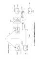
図20は、図2,図12,図16と同様の形式で第4の実施の形態におけるヘッドホン1の構成例を示している。なお図2、図12、図16と同一部分には同一符号を付し、説明を省略する。
この図20においては、ノイズキャンセリングシステム非搭載のため、外側マイクロホン4の収音音声信号、内側マイクロホン5は装着検出のためにのみ使用されることとなる。
外側マイクロホン4で収音された音声信号がマイクアンプ19,A/D変換器12を介して装着状態検出部24に供給され、また内側マイクロホン5収音された音声信号がマイクアンプ18,A/D変換器13を介して装着状態検出部24に供給される。また再生音声信号もA/D変換器11を介して装着状態検出部24に供給される。
他は既述の実施の形態と同様である。FIG. 20 shows an example of the configuration of the
In FIG. 20, since the noise canceling system is not mounted, the collected sound signal of the
The sound signal picked up by the
Others are the same as the embodiment described above.
まず、再生装置100からの再生音声信号(S)の入力がない場合において、内側マイクロホン5及び外側マイクロホン4で得られる音声信号について、図18で説明する。
既述の実施の形態と同様、外来ノイズの音源N、サウンドフィールド301(音響経路F、F’)の特性をF0、F1、マイク&マイクアンプ303及びマイク&マイクアンプ308の特性をMとする。First, audio signals obtained by the
As in the above-described embodiment, the characteristics of the external noise source N, the sound field 301 (acoustic paths F and F ′) are F0 and F1, and the characteristics of the microphone &
内側マイクロホン5、外側マイクロホン4は装着検出にのみ使用され、また再生音声入力がないことから、図18に示すように、音圧P、Rは、音源Nからの外来音のみによる音圧となる。 Since the
式74から式78を参照する。
非装着状態と仮定する場合、内側マイクロホン5が収音する音圧P(P0とする)は式74で表される。
装着状態と仮定する場合、内側マイクロホン5が収音する音圧P(P1とする)は式75で表される。
外側マイクロホン4が収音した音圧Rは式76で表される。
内側マイクロホン5と外側マイクロホン4で得られる音圧について比を算出すると、非装着状態では式77が得られる。式77は非装着状態基準値となり、上述の式6と等しい。
また装着状態では式78が得られる。式78は装着状態基準値となり、上述の式7と等しい。Assuming the non-wearing state, the sound pressure P (referred to as P0) collected by the
Assuming the wearing state, the sound pressure P (referred to as P1) collected by the
The sound pressure R collected by the
When the ratio is calculated for the sound pressures obtained by the
In the mounted state, Formula 78 is obtained. Expression 78 is the wearing state reference value, and is equal to
ヘッドホン1の動作中は、以下の動作を行う。式79〜式81を参照する。
既述の実施の形態と同様に、ヘッドホン1の動作中に内側マイクロホン5と外側マイクロホン4で収音した「P」と「R」から、常に式79の「T」を計算する。この「T」は非装着状態の場合、理想通りであれば式77と等しくなり、は装着状態の場合、理想通りであれば式78と等しくなる。
よって式80、式81で距離d0、d1を求めて比較する。
式80の距離d0は、式79の算出値「T」と非装着状態基準値(=1)の距離を示し、式81の距離d1は、算出値「T」と装着状態基準値(=F1/F0)の距離を示す。
この距離d0、d1を比較し、d0<d1であれば、非装着状態と判断する。d0≧d1であれば、装着状態と判断する。
このような考え方で装着/非装着を判定できる。As in the above-described embodiment, “T” in Expression 79 is always calculated from “P” and “R” collected by the
Therefore, the distances d0 and d1 are obtained and compared using the
The distance d0 in
The distances d0 and d1 are compared, and if d0 <d1, it is determined that they are not attached. If d0 ≧ d1, it is determined that the wearing state.
Wearing / non-wearing can be determined based on this concept.
図22は再生音声信号(S)の入力を考慮した場合である。
内側マイクロホン5で収音される音圧Pに関し、再生音声信号Sの成分が加わる。即ち音圧Pにおいては、再生音声信号Sについて、イコライザ305での信号処理特性「E」、パワーアンプ306の特性「A」、ドライバ&アコースティック307の特性「H」、マイク&マイクアンプ303の特性「M」が与えられた成分が含まれる。
すると、上記同様の考え方で各式は以下のようになる。FIG. 22 shows a case where the input of the reproduced audio signal (S) is considered.
Regarding the sound pressure P collected by the
Then, with the same idea as above, each formula is as follows.
非装着状態と仮定する場合、内側マイクロホン5が収音する音圧P(P0とする)は式82で表される。
装着状態と仮定する場合、内側マイクロホン5が収音する音圧P(P1とする)は式83で表される。
外側マイクロホン4が収音した音圧Rは式84で表される。Assuming the non-wearing state, the sound pressure P (P 0) that is picked up by the
Assuming the wearing state, the sound pressure P (referred to as P1) collected by the
The sound pressure R picked up by the
式82を変形して式85のQ0が得られる。
式83を変形して式86のQ1が得られる。
内側マイクロホン5と外側マイクロホン4で得られる音圧について比を算出すると、非装着状態では式87が得られ、これは非装着状態基準値となり、上述の式6と等しい。
装着状態と仮定する場合は式88が得られ、これは装着状態基準値となり、上述の式7と等しい。
Equation 83 is transformed to obtain Q1 of Equation 86.
When the ratio is calculated for the sound pressures obtained by the
In the case of assuming the wearing state, Equation 88 is obtained, which is the wearing state reference value, and is equal to
ヘッドホン1の動作中は、以下の動作を行う。式89〜式92を参照する。
ヘッドホン1の動作中は、内側マイクロホン5で収音した信号「P」、外側マイクロホン4で収音した信号「R」から、常時、式89、式90の「T0」「T1」を計算する。
式89の算出値T0は、非装着状態を仮定した場合の、外側マイクロホン4で得られる音声信号と内側マイクロホン5で得られる音声信号との信号比較結果の値となり、実際に非装着状態であったとすると、算出値T0は、理想通りであれば式87の非装着状態基準値(=1)と等しくなる。
また式90の算出値T1は、装着状態を仮定した場合の、外側マイクロホン4で得られる音声信号と内側マイクロホン5で得られる音声信号との信号比較結果の値となり、実際に装着状態であったとすると、算出値T1は、理想通りであれば式88の装着状態基準値(=F1/F0)と等しくなる。During the operation of the
The calculated value T0 in Expression 89 is a value of a signal comparison result between the audio signal obtained by the
Further, the calculated value T1 of Expression 90 is the value of the signal comparison result between the audio signal obtained by the
そこで算出値「T0」「T1」について、式91,式92のように理想値との距離d0、d1を求める。距離d0は、算出値「T0」と非装着状態基準値(=1)の距離を示し、距離d1は、算出値「T1」と装着状態基準値(=F1/F0)の距離を示す。
そして、この距離d0、d1を比較する。もし、d0<d1であれば、非装着状態と判断する。d0≧d1であれば、装着状態と判断する。
このように、外側マイクロホン4で得られる音声信号と内側マイクロホン5で得られる音声信号との信号比較結果について、非装着状態基準値、装着状態基準値との類似性(距離)を判断することで、装着/非装着を判定できる。Therefore, distances d0 and d1 from the ideal values are calculated for the calculated values “T0” and “T1” as shown in Equations 91 and 92. The distance d0 indicates the distance between the calculated value “T0” and the non-wearing state reference value (= 1), and the distance d1 indicates the distance between the calculated value “T1” and the wearing state reference value (= F1 / F0).
Then, the distances d0 and d1 are compared. If d0 <d1, it is determined that it is not attached. If d0 ≧ d1, it is determined that the wearing state.
As described above, the similarity (distance) between the non-wearing state reference value and the wearing state reference value is determined for the signal comparison result between the sound signal obtained by the
以上のように、音楽等の再生音声をヘッドホン1で音響出力している場合でも、結局は再生音声がない場合と同様に、装着状態検出を行うことができる。
実際のヘッドホン1では、上記式82〜式92で述べた考え方で装着状態検出を行うようにすれば良い。即ちヘッドホン動作中はリアルタイム処理として式89、式90の算出を行うようにする。再生音声信号Sの入力がない場合には、式89、式90は式79と等しくなる(T0=T1=T)ためである。
また最終的に式91,式92で得られた距離d0、d1の比較を行う場合に、係数を用いて(d0・k0)と(d1・k1)の比較を行うようにしてもよい。As described above, even when the reproduced sound such as music is acoustically output from the
In the
Further, when comparing the distances d0 and d1 finally obtained by the equations 91 and 92, a comparison may be made between (d0 · k0) and (d1 · k1) using a coefficient.
以上のとおり、ノイズキャンセリングシステムを搭載しないヘッドホン1の場合も、既述の実施の形態と同様の考え方で装着検出を行うことができる。
実際の処理は第1の実施の形態と同様に行えばよい。
As described above, even in the case of the
Actual processing may be performed in the same manner as in the first embodiment.
<6.第5の実施の形態>
実際の処理としては、第1の実施の形態において図7〜図9で説明したように、周波数領域での比較処理を行う判定処理例を述べたが、装着判定のための比較処理は時間軸での振幅比較として行ってもよい。
第5の実施の形態として時間軸振幅比較で装着判定を行う処理例を説明する。<6. Fifth embodiment>
As actual processing, as described with reference to FIGS. 7 to 9 in the first embodiment, an example of determination processing in which comparison processing in the frequency domain is performed has been described. You may perform as an amplitude comparison in.
As a fifth embodiment, a processing example in which mounting determination is performed by time axis amplitude comparison will be described.
図23は、第5の実施の形態としての装着状態検出部24の構成例を示している。これは、例えば図2、図12、図16、図20の各構成例における装着状態検出部24の内部構成と考えれば良い。 FIG. 23 shows a configuration example of the wearing
外側マイクロホン4で収音され、マイクアンプ19、A/D変換器12(図2等参照)を介して装着状態検出部24に入力された外側マイク入力信号は、バンドパスフィルタ61−1〜61−nに入力される。
バンドパスフィルタ61−1〜61−nにより、外側マイク入力信号はn個の周波数帯域(第1帯域〜第n帯域)毎に抽出される。Outer microphone input signals collected by the
The band-pass filters 61-1 to 61-n extract the outer microphone input signal for every n frequency bands (first to nth bands).
また内側マイクロホン5で収音され、マイクアンプ19、A/D変換器12(図2等参照)を介した内側マイク入力信号と、A/D変換器11(図2等参照)を介した再生音声信号は、装着状態検出部24において再生音声信号成分除去部60に入力される。再生音声信号成分除去部60では、内側マイク入力信号から再生音声信号を減算して、再生音声信号成分を除去した内側マイクロホン5の収音音声信号成分を得る。この再生音声信号成分を除去した内側マイクロホン5の収音音声信号成分が、バンドパスフィルタ64−1〜64−nに入力され、バンドパスフィルタ64−1〜64−nにより、n個の周波数帯域(第1帯域〜第n帯域)毎に抽出される。 Also, the sound is picked up by the
バンドパスフィルタ61−1〜61−nから出力される外側マイク入力信号についての各帯域の信号は、それぞれ絶対値化部(ABS部)62−1〜62−nで絶対値化され、ローパスフィルタ63−1〜63−nで高域除去されてエンベロープ化される。
またバンドパスフィルタ64−1〜64−nから出力される、再生音声信号成分が除去された内側マイク入力信号についての各帯域の信号は、それぞれ絶対値化部(ABS部)65−1〜65−nで絶対値化され、ローパスフィルタ66−1〜66−nで高域除去されてエンベロープ化される。The signals in the respective bands of the outer microphone input signals output from the band pass filters 61-1 to 61-n are converted into absolute values by absolute value converting units (ABS units) 62-1 to 62-n, respectively, and the low pass filter is obtained. High frequencies are removed at 63-1 to 63-n and enveloped.
In addition, the signals in the respective bands of the inner microphone input signals from which the reproduction audio signal components are removed, which are output from the band pass filters 64-1 to 64-n, are respectively absolute value units (ABS units) 65-1 to 65-65. -N is converted to an absolute value, and high-frequency is removed by low-pass filters 66-1 to 66 -n to be enveloped.
T0算出部68−1〜68−n、T1算出部69−1〜69−nが用意される。T0算出部68−1〜68−nは、上述の式8等に示した算出値T0の算出を行う。T1算出部69−1〜69−nは、上述の式9等に示した算出値T1の算出を行う。 T0 calculators 68-1 to 68-n and T1 calculators 69-1 to 69-n are prepared. The T0 calculators 68-1 to 68-n calculate the calculated value T0 shown in the above equation 8 and the like. The T1 calculating units 69-1 to 69-n calculate the calculated value T1 shown in the above-described equation 9 and the like.
ローパスフィルタ63−1の出力と、ローパスフィルタ66−1の出力は、第1帯域の外側マイク入力信号(上述の「R」に相当)と内側マイク入力信号(上述の「P」に相当)として、T0算出部68−1及びT1算出部69−1に供給される。T0算出部68−1では、第1帯域の「T0」が求められ、T1算出部69−1では、第1帯域の「T1」が求められる。
同様に、ローパスフィルタ63−2の出力と、ローパスフィルタ66−2の出力は、第2帯域の外側マイク入力信号と内側マイク入力信号として、T0算出部68−2及びT1算出部69−2に供給される。T0算出部68−2では、第2帯域の「T0」が求められ、T1算出部69−2では、第2帯域の「T1」が求められる。
同様に、ローパスフィルタ63−nの出力と、ローパスフィルタ66−nの出力は、第n帯域の外側マイク入力信号と内側マイク入力信号として、T0算出部68−n及びT1算出部69−nに供給される。T0算出部68−nでは、第n帯域の「T0」が求められ、T1算出部69−nでは、第n帯域の「T1」が求められる。The output of the low-pass filter 63-1 and the output of the low-pass filter 66-1 are as an outer microphone input signal (corresponding to “R” described above) and an inner microphone input signal (corresponding to “P” described above) of the first band. , T0 calculator 68-1, and T1 calculator 69-1. In the T0 calculation unit 68-1, “T0” of the first band is obtained, and in the T1 calculation unit 69-1, “T1” of the first band is obtained.
Similarly, the output of the low-pass filter 63-2 and the output of the low-pass filter 66-2 are sent to the T0 calculating unit 68-2 and the T1 calculating unit 69-2 as an outer microphone input signal and an inner microphone input signal in the second band. Supplied. The T0 calculation unit 68-2 calculates “T0” of the second band, and the T1 calculation unit 69-2 calculates “T1” of the second band.
Similarly, the output of the low-pass filter 63-n and the output of the low-pass filter 66-n are sent to the T0 calculating unit 68-n and the T1 calculating unit 69-n as an outer microphone input signal and an inner microphone input signal in the nth band. Supplied. The T0 calculating unit 68-n calculates “T0” of the nth band, and the T1 calculating unit 69-n calculates “T1” of the nth band.
メモリ25には、各帯域のそれぞれについての非装着状態基準値(Q0/R=1)、及び装着状態基準値(Q1/R=F1/F0)が記憶されている。
例えば予め、図6で説明したような測定を、ホワイトノイズ等をバンドパスフィルタ61−1〜61−nと同じ通過帯域のバンドパスフィルタを介して音源110から出力した状態で行う。そして第1帯域から第n帯域のそれぞれについて、非装着状態基準値と装着状態基準値(この場合例えば振幅値)をメモリ25に記憶させておく。The
For example, the measurement described with reference to FIG. 6 is performed in a state where white noise or the like is output from the
差分算出部70−1〜70−nでは、それぞれT0算出部68−1〜68−nの出力(T0)と、対応する帯域の非装着状態基準値の差分を算出する。
差分算出部71−1〜71−nでは、それぞれT1算出部69−1〜69−nの出力(T1)と、対応する帯域の装着状態基準値の差分を算出する。The difference calculation units 70-1 to 70-n calculate the difference between the output (T0) of the T0 calculation units 68-1 to 68-n and the non-wearing state reference value of the corresponding band, respectively.
The difference calculation units 71-1 to 71-n calculate the difference between the output (T1) of the T1 calculation units 69-1 to 69-n and the wearing state reference value of the corresponding band, respectively.
差分算出部70−1〜70−nの出力は係数器80−1〜80−nを介して判定部82に供給される。差分算出部71−1〜71−nの出力は係数器81−1〜81−nを介して判定部82に供給される。
係数器80−1〜80−n、及び係数器81−1〜81−nの係数=1とすれば、判定部82には第1帯域〜第n帯域のそれぞれについての、算出値T0と非装着状態基準値の差分(式10等のd0に相当)、及び算出値T1と装着状態基準値の差分(式11等のd1に相当)が供給されることになる。
判定部82はこれらの入力から装着/非装着の判定を行う。The outputs of the difference calculation units 70-1 to 70-n are supplied to the
If the coefficients of the coefficient multipliers 80-1 to 80-n and the coefficient multipliers 81-1 to 81-n are set to 1, the
The
判定部82は、例えば図24の処理で装着判定を行うことができる。
即ち各周波数帯域において非装着と判定した回数をカウントし、全周波数帯域が規定回数以上連続した場合に非装着と判定、もしくは規定割合以上に達した場合に非装着と判定する。The
That is, the number of times determined as non-wearing in each frequency band is counted, and it is determined as non-wearing when the entire frequency band continues for a specified number of times or more, and it is determined as non-wearing when it reaches a specified ratio or more.
判定部82は、ステップF301でカウンタ初期化を行う。例えば周期カウンタ、非装着カウンタを初期化する。周期カウンタは、一定の検出単位期間となる一周期をカウントするカウンタであり、非装着カウンタは、非装着状態と検出される状態の継続時間をカウントするカウンタである。この場合、非装着カウンタとしては第1帯域用非装着カウンタから第n帯域用非装着カウンタが用いられる。 The
判定部82はステップF302で、第1帯域の装着/非装着の判定を行う。即ち第1帯域についての、算出値T0と非装着状態基準値の差分d0と、算出値T1と装着状態基準値の差分d1を比較して、装着/非装着判定を行う。
そして非装着状態と判定した場合は、ステップF303で第1帯域用非装着カウンタをインクリメントする。一方、装着状態と判定した場合はステップF304で第1帯域用非装着カウンタをクリアする。In step F302, the
If it is determined as the non-wearing state, the first band non-wearing counter is incremented in step F303. On the other hand, if it is determined that the wearing state, the first band non-wearing counter is cleared in step F304.
また判定部82はステップF305で、第2帯域の装着/非装着の判定を行う。即ち第2帯域についての、算出値T0と非装着状態基準値の差分d0と、算出値T1と装着状態基準値の差分d1を比較して、装着/非装着判定を行う。
そして非装着状態と判定した場合は、ステップF306で第2帯域用非装着カウンタをインクリメントする。一方、装着状態と判定した場合はステップF307で第2帯域用非装着カウンタをクリアする。
このような処理を第n帯域まで行う(ステップF308,F309,F310)。In step F305, the
If it is determined that the wearer is in the non-wearing state, the second band non-wearing counter is incremented in step F306. On the other hand, if it is determined that the wearing state, the second band non-wearing counter is cleared in step F307.
Such processing is performed up to the nth band (steps F308, F309, and F310).
各帯域についての以上の処理を行ったら、判定部82はステップF311で周期カウンタをインクリメントする。
そして判定部82はステップF312で、第1帯域用非装着カウンタから第n帯域用非装着カウンタの値がすべて所定の閾値を越えているか否かを確認する。
第1帯域用非装着カウンタから第n帯域用非装着カウンタの値がすべて所定の閾値を越えていたら、ステップF313で最終結果として「非装着」とし、非装着状態を検出信号Sdetにより制御部15に通知する。
一方、以上を満たしていなければ、ステップF314で最終結果として「装着」とし、装着状態を検出信号Sdetで制御部15に通知する。After performing the above processing for each band, the
In step F312, the
If all the values of the first band non-wearing counter to the n-th band non-wearing counter exceed the predetermined threshold, the final result is “non-wearing” in step F313, and the non-wearing state is detected by the
On the other hand, if the above is not satisfied, the final result is “attached” in step F314, and the attached state is notified to the
判定部82はステップF315で周期カウンタの値が所定の一周期としてのカウンタ値を越えたか否かを確認する。越えていなければ、ステップF302からの処理をそのまま継続する。一周期に達していたら、判定部82は第1周期非装着カウンタ〜第n周期非装着カウンタをクリアする。さらに判定部82はステップF316で周期カウンタをクリアしてステップF302に戻る。 In step F315, the
装着状態検出部24は、以上の処理を、例えば電源オン中は継続して実行する。これにより、周期カウンタで計測される周期単位で、全体域での非装着判定状態の判定が所定時間以上継続した場合に、「非装着」としての検出結果が制御部15に通知される。 The wearing
この第5の実施の形態の場合、装着/非装着の判定の基本的な考え方は第1〜第4の実施の形態と同様であるが、判定のための具体的な比較手法については、帯域毎の「P」「R」の比較結果を時系列で非装着状態基準値及び装着状態基準値と比較していくというものとなる。 In the case of the fifth embodiment, the basic concept of the determination of wearing / non-wearing is the same as that of the first to fourth embodiments, but the specific comparison method for the determination is a band. The comparison results of “P” and “R” for each time are compared with the non-wearing state reference value and the wearing state reference value in time series.
なお、このように帯域分割して判定を行う場合、係数器80−1〜80−n、及び係数器81−1〜81−nの係数設定によって、特定の帯域に重み付けすることも可能である。
例えば内側マイクロホン5と外側マイクロホン4の各収音信号で振幅差分が生ずる支配的な帯域について重みを与えることで判定精度を上げることもできる。
或いは、ノイズ環境に応じて支配的な帯域が変化することから、環境(例えば電車内、飛行機内、屋外などの別)に応じて、各帯域の係数設定を行い、環境に応じて的確な装着判定を行うことも考えられる。
さらに判定処理の継続中に差分が大きい支配的な帯域を判断し、その帯域の係数を高くするような重み付けを行うようにしてもよい。In the case of performing the determination by dividing the band in this way, it is possible to weight a specific band by setting the coefficients of the coefficient units 80-1 to 80-n and the coefficient units 81-1 to 81-n. .
For example, it is possible to increase the determination accuracy by giving weights to dominant bands in which amplitude differences occur between the sound pickup signals of the
Or, because the dominant band changes according to the noise environment, set the coefficient for each band according to the environment (for example, inside a train, inside a plane, outdoors, etc.), and wear it accurately according to the environment It is also possible to make a determination.
Further, a dominant band having a large difference may be determined during the determination process, and weighting may be performed to increase the coefficient of the band.
また、図23の説明では帯域分割を第1帯域〜第n帯域としたが、nは1以上である。例えば1つのバンドパスフィルタで支配的な帯域を抽出して判定処理を行ってもよいし、3つの帯域、4つの帯域、5つの帯域など、多数の帯域を用いてもよい。
また第1帯域〜第n帯域というn個の帯域で可聴帯域の全てをカバーする必要はない。In the description of FIG. 23, the band division is defined as the first band to the nth band, but n is 1 or more. For example, a dominant band may be extracted by one band pass filter and the determination process may be performed, or a large number of bands such as three bands, four bands, and five bands may be used.
Further, it is not necessary to cover the entire audible band with n bands from the first band to the nth band.
図24の処理に関しては、図11で述べたような変形例も考えられる。即ちステップF304,F307,F310の非装着カウンタクリアは行わないようにし、非装着カウンタは継続時間でなく、一周期内の累積時間を表すものとしてもよい。
またステップF312では、全ての帯域についての非装着カウンタが閾値を越えた場合というAND条件で最終結果を非装着状態としたが、OR条件、もしくは所定数の帯域の非装着カウンタが閾値を越えた場合など、他の条件で最終結果を非装着状態とする例も考えられる。With respect to the processing of FIG. 24, a modification as described in FIG. 11 is also conceivable. In other words, the non-mounting counter clear in steps F304, F307, and F310 is not performed, and the non-mounting counter may represent the accumulated time within one cycle instead of the duration.
In step F312, the final result is set to the non-wearing state under the AND condition that the non-wearing counters for all the bands exceed the threshold value, but the OR condition or the non-wearing counters for a predetermined number of bands has exceeded the threshold value. In some cases, the final result may be in a non-wearing state under other conditions.
また装着状態検出部24の構成として図25のような構成も考えられる。なお、図23と同一部分は同一符号として説明を省略する。
図25の構成例は、図23における絶対値化部62−1〜62−n、65−1〜65−nでの絶対値化処理と、ローパスフィルタ63−1〜63−n、66−1〜66−nでのエンベロープ化処理を省略したものである。他は図23と同様である。
このような構成でも装着/非装着の判定を行うことができる。
Further, a configuration as shown in FIG. In addition, the same part as FIG. 23 is abbreviate | omitted description with the same code | symbol.
The configuration example of FIG. 25 includes absolute value processing in the absolute value converting units 62-1 to 62-n and 65-1 to 65-n in FIG. 23, and low-pass filters 63-1 to 63-n and 66-1. The envelope processing at ~ 66-n is omitted. Others are the same as FIG.
Even with such a configuration, it is possible to determine mounting / non-mounting.
<7.変形例>
以上、各種実施の形態を説明してきたが、さらに多様な変形例が考えられる。
実施の形態のヘッドホン1としては、頭部装着の密閉型の他、インナーイヤータイプ、カナルタイプと呼ばれるような形態のものなど、他のタイプのヘッドホン装置にも適用できる。また片耳タイプのヘッドホン装置でも本開示の技術は有効である。
またステレオヘッドホンに限らずモノラルヘッドフォンでも本開示の技術を適用できる。
またアクティブヘッドホンとして、ノイズキャンセリングシステム搭載、非搭載のヘッドホンや、ブルートゥース等の無線通信機能搭載のヘッドホン、或いは音響処理のためのアクティブ回路搭載のヘッドホンなど、広く電池使用のヘッドホンに本開示の技術は好適である。
また、内側マイクロホン5或いは外側マイクロホン4は、通話用のマイクロホンとして兼用することもでき、その意味で携帯電話機等に接続して用いるヘッドホンにも好適である。<7. Modification>
While various embodiments have been described above, various modifications can be considered.
The
Further, the technology of the present disclosure can be applied to mono headphones as well as stereo headphones.
In addition, as active headphones, the technology of the present disclosure is widely applied to headphones using batteries, such as headphones with or without a noise canceling system, headphones with a wireless communication function such as Bluetooth, or headphones with an active circuit for acoustic processing. Is preferred.
In addition, the
図2、図12、図16、図20では、装着状態検出部24と制御部15を別体として示したが、装着状態検出部24としての動作を制御部15としてのマイクロコンピュータ等が実行してもよい。即ち制御部15と装着判定部24は一体のハードウエア構成としてもよい。 2, 12, 16, and 20, the mounting
各実施の形態では、Lチャンネル・Rチャンネルの一方のみで説明したが、両チャンネルで同様の装着検出を独立して行ってもよいし、まとめて行ってもよい。
まとめて行う場合とは、例えば外側マイクロホン4L、4Rの入力音声信号をミックスして装着状態検出部24に供給し、また内側マイクロホン5L、5Rの入力音声信号をミックスして装着状態検出部24に供給するようにすればよい。
さらに、一方のチャンネルのみで装着検出を行うようにしても良い。In each of the embodiments, only one of the L channel and the R channel has been described. However, the same attachment detection may be performed independently or collectively for both channels.
In the case of performing collectively, for example, the input sound signals of the
Further, the attachment detection may be performed only on one channel.
L・R各チャンネルで独立して装着状態検出を行う場合、Lチャンネルの装着/非装着の検出結果とRチャンネルの装着/非装着の検出結果がそれぞれ得られるが、制御部15は多様な処理例が考えられる。
例えばL・Rチャンネルのアンド条件で非装着となったら電源オフ制御を行うようにしたり、或いはオア条件として一方のチャンネルで非装着と検出されたら電源オフ制御を行うようにしてもよい。むやみに電源オフとしないことを重視すれば、アンド条件が好ましいし、なるべく電源オフとしたいのであればオア条件が好ましい。
また、装着/非装着の検出結果に応じた制御部15の制御は電源オフ制御に限られない。
例えば非装着と判断された場合に、再生音声の音量を下げたり、一方のチャンネルのみ非装着と判定されたら、L・Rチャンネルの再生音声をモノラルミックスして、装着状態のチャンネルのドライバユニット3から音響出力させるような制御も考えられる。When the attachment state detection is performed independently for each of the L and R channels, the detection result of the attachment / non-attachment of the L channel and the detection result of the attachment / non-attachment of the R channel can be obtained, respectively. Examples are possible.
For example, the power-off control may be performed when the LR channel is not installed under the AND condition, or the power-off control may be performed when it is detected that the channel is not installed as an OR condition. The AND condition is preferable if importance is placed on not turning off the power, and the OR condition is preferable if the power is turned off as much as possible.
Further, the control of the
For example, when it is determined that it is not attached, the volume of the playback sound is lowered, or if it is determined that only one of the channels is not attached, the playback sound of the L / R channels is monaurally mixed, and the
また電源オン制御を行うようにしてもよい。例えば電源オフ時(スタンバイ状態)にも装着状態検出部による装着検出動作が実行するようにする。そして装着状態と検出されたら制御部15は電源オン制御及びスリープ状態からの起動を行う。このようにすれば、ユーザが装着すれば電源オンとなり、外せば電源オフとなるアクティブヘッドホンを実現できることになる。 Further, power on control may be performed. For example, the mounting detection operation by the mounting state detection unit is executed even when the power is turned off (standby state). When the mounting state is detected, the
また実施の形態で説明したように装着状態検出に用いる装着状態基準値(F1/F0)は、ユーザ個人毎に最適値が異なる。ユーザの頭部や耳介周辺の形状、装着部分の頭髪の量、装着の癖などから、ハウジング2内の密閉状況が異なるためである。そこで、ユーザが装着した状態で装着状態基準値の測定を行ったり、装着状態基準値のキャリブレーションを行うことで、実際に使用するユーザに合った装着状態基準値を記憶するようにすることも考えられる。 Further, as described in the embodiment, the optimum value of the wearing condition reference value (F1 / F0) used for wearing condition detection differs for each individual user. This is because the sealed state in the
また外側マイクロホン4で得られる音声信号と内側マイクロホン5で得られる音声信号との信号比較結果について、非装着状態基準値、及び装着状態基準値と比較して類似性判断を行う場合、周波数軸上での振幅比較や時間軸上での振幅比較の例を挙げたが、例えば各周波数帯域の信号位相差を検出するような比較処理を行うことも考えられる。 In addition, regarding the signal comparison result between the audio signal obtained by the
なお本技術は以下のような構成も採ることができる。
(1)使用者に装着された状態で、外来音が遮蔽物を介さないで収音される位置に取り付けられる外側マイクロホンと、
使用者に装着された状態で、外来音が遮蔽物を介して収音される位置に取り付けられる内側マイクロホンと、
音響出力を行うドライバユニットと、
上記外側マイクロホンで得られる音声信号と上記内側マイクロホンで得られる音声信号との信号比較結果と、予め記憶した非装着状態における外来音到来時の上記外側マイクロホンで得られる音声信号と上記内側マイクロホンで得られる音声信号との信号比較結果である非装着状態基準値と、予め記憶した装着状態における外来音到来時の上記外側マイクロホンで得られる音声信号と上記内側マイクロホンで得られる音声信号との信号比較結果である装着状態基準値とを用いて、装着状態か非装着状態かを検出する装着状態検出部と、
を備えたヘッドホン装置。
(2)上記装着状態検出部は、
上記外側マイクロホンで得られる音声信号と上記内側マイクロホンで得られる音声信号との信号比較結果について、上記非装着状態基準値、及び上記装着状態基準値との各類似性判断を行って、装着状態か非装着状態かを検出する上記(1)に記載のヘッドホン装置。
(3)上記装着状態検出部は、上記類似性判断として、
上記外側マイクロホンで得られる音声信号と上記内側マイクロホンで得られる音声信号との信号比較結果としての周波数特性を、上記非装着状態基準値及び上記装着状態基準値としての周波数特性と比較する処理を行う上記(2)に記載のヘッドホン装置。
(4)上記装着状態検出部は、上記類似性判断として、
上記外側マイクロホンで得られる音声信号と上記内側マイクロホンで得られる音声信号との信号比較結果としての時間軸振幅を、上記非装着状態基準値及び上記装着状態基準値としての時間軸振幅と比較する処理を行う上記(2)に記載のヘッドホン装置。
(5)上記装着状態検出部は、
一定の周期毎に、上記類似性判断の結果、非装着状態と判定される継続期間又は累積時間が閾値を越えた場合に、非装着状態との検出結果を出力する上記(2)乃至(4)のいずれかに記載のヘッドホン装置。
(6)収音した外来音信号からノイズキャンセリング信号を生成し、該ノイズキャンセリング信号を上記ドライバユニットから出力させる音声信号とするノイズキャンセル処理部をさらに備えるとともに、
上記ノイズキャンセル処理部へ供給する外来音信号は、上記外側マイクロホンと上記内側マイクロホンの一方又は両方で得る構成とされている上記(1)乃至(5)のいずれかに記載のヘッドホン装置。
(7)外部装置から入力された音声信号を上記ドライバユニットから出力させる音声信号として処理する音声信号処理部をさらに備える上記(1)乃至(6)のいずれかに記載のヘッドホン装置。
(8)上記装着状態検出部によって非装着状態が検出された場合に、電源オフ制御を行う制御部を、さらに備えた上記(1)乃至(7)のいずれかに記載のヘッドホン装置。In addition, this technique can also take the following structures.
(1) An outer microphone that is attached to a position where foreign sounds are picked up without passing through a shield in a state where it is worn by a user;
An inner microphone that is attached to a position where foreign sounds are picked up through a shield while being worn by the user;
A driver unit for sound output;
The signal comparison result between the sound signal obtained by the outer microphone and the sound signal obtained by the inner microphone, the sound signal obtained by the outer microphone when the external sound arrives in a non-wearing state stored in advance, and the inner microphone. Signal comparison result between a non-wearing state reference value that is a signal comparison result with a sound signal to be obtained and a sound signal obtained with the outer microphone and a sound signal obtained with the inner microphone when a foreign sound arrives in a wearing state stored in advance A wearing state detection unit that detects whether the wearing state or the non-wearing state using the wearing state reference value that is,
Headphone device equipped with.
(2) The wearing state detection unit
Regarding the signal comparison result between the audio signal obtained by the outer microphone and the audio signal obtained by the inner microphone, the similarity between the non-wearing state reference value and the wearing state reference value is determined to determine whether the sound is obtained. The headphone device according to (1), wherein the headphone device detects whether it is not attached.
(3) The wearing state detection unit performs the similarity determination as follows.
A process of comparing the frequency characteristic as a signal comparison result between the sound signal obtained by the outer microphone and the sound signal obtained by the inner microphone with the frequency characteristic as the non-wearing state reference value and the wearing state reference value is performed. The headphone device according to (2) above.
(4) The wearing state detection unit performs the similarity determination as follows.
Processing for comparing the time axis amplitude as a signal comparison result between the audio signal obtained by the outer microphone and the audio signal obtained by the inner microphone with the time axis amplitude as the non-wearing state reference value and the wearing state reference value The headphone device according to (2), wherein:
(5) The wearing state detection unit
(2) to (4) that output the detection result of the non-wearing state when the duration or cumulative time determined to be the non-wearing state exceeds the threshold value as a result of the similarity determination, at regular intervals. The headphone device according to any one of the above.
(6) A noise canceling unit that generates a noise canceling signal from the collected external sound signal and uses the noise canceling signal as an audio signal to be output from the driver unit;
The headphone device according to any one of (1) to (5), wherein the external sound signal supplied to the noise cancellation processing unit is configured to be obtained by one or both of the outer microphone and the inner microphone.
(7) The headphone device according to any one of (1) to (6), further including an audio signal processing unit that processes an audio signal input from an external device as an audio signal to be output from the driver unit.
(8) The headphone device according to any one of (1) to (7), further including a control unit that performs power-off control when a non-wearing state is detected by the wearing state detection unit.
1 ヘッドホン、2L,2R ハウジング、3,3L,3R ドライバユニット、4,4L,4R 外側マイクロホン、5,5L,5R 内側マイクロホン、6 信号処理装置、10 演算部、15 制御部、16 電源部、21 再生音声信号処理部、22 ノイズキャンセリング信号処理部、24 装着状態検出部、25 メモリ DESCRIPTION OF
Claims (9)
Translated fromJapanese使用者に装着された状態で、外来音が遮蔽物を介して収音される位置に取り付けられる内側マイクロホンと、
音響出力を行うドライバユニットと、
上記外側マイクロホンで得られる音声信号と上記内側マイクロホンで得られる音声信号との信号比較結果と、予め記憶した非装着状態における外来音到来時の上記外側マイクロホンで得られる音声信号と上記内側マイクロホンで得られる音声信号との信号比較結果である非装着状態基準値と、予め記憶した装着状態における外来音到来時の上記外側マイクロホンで得られる音声信号と上記内側マイクロホンで得られる音声信号との信号比較結果である装着状態基準値とを用いて、装着状態か非装着状態かを検出する装着状態検出部と、
を備え、
上記装着状態検出部は、
上記外側マイクロホンで得られる音声信号と上記内側マイクロホンで得られる音声信号との信号比較結果について、上記非装着状態基準値、及び上記装着状態基準値との各類似性判断を行って、装着状態か非装着状態かを検出する
ヘッドホン装置。An outer microphone that is attached to a position where external sounds are picked up without passing through a shield while being worn by the user;
An inner microphone that is attached to a position where foreign sounds are picked up through a shield while being worn by the user;
A driver unit for sound output;
The signal comparison result between the sound signal obtained by the outer microphone and the sound signal obtained by the inner microphone, the sound signal obtained by the outer microphone when the external sound arrives in a non-wearing state stored in advance, and the inner microphone. Signal comparison result between a non-wearing state reference value that is a signal comparison result with a sound signal to be obtained and a sound signal obtained with the outer microphone and a sound signal obtained with the inner microphone when a foreign sound arrives in a wearing state stored in advance A wearing state detection unit that detects whether the wearing state or the non-wearing state using the wearing state reference value that is,
With
The wearing state detection unit
Regarding the signal comparison result between the audio signal obtained by the outer microphone and the audio signal obtained by the inner microphone, the similarity between the non-wearing state reference value and the wearing state reference value is determined to determine whether the sound is obtained. Headphone devicethat detects whether it is not worn .
上記外側マイクロホンで得られる音声信号と上記内側マイクロホンで得られる音声信号との信号比較結果としての周波数特性を、上記非装着状態基準値及び上記装着状態基準値としての周波数特性と比較する処理を行う請求項1に記載のヘッドホン装置。The wearing state detection unit, as the similarity determination,
A process of comparing the frequency characteristic as a signal comparison result between the sound signal obtained by the outer microphone and the sound signal obtained by the inner microphone with the frequency characteristic as the non-wearing state reference value and the wearing state reference value is performed. The headphone device according to claim 1.
上記外側マイクロホンで得られる音声信号と上記内側マイクロホンで得られる音声信号との信号比較結果としての時間軸振幅を、上記非装着状態基準値及び上記装着状態基準値としての時間軸振幅と比較する処理を行う請求項1に記載のヘッドホン装置。The wearing state detection unit, as the similarity determination,
Processing for comparing the time axis amplitude as a signal comparison result between the audio signal obtained by the outer microphone and the audio signal obtained by the inner microphone with the time axis amplitude as the non-wearing state reference value and the wearing state reference value The headphone device according to claim 1 which performs.
一定の周期毎に、上記類似性判断の結果、非装着状態と判定される継続期間又は累積時間が閾値を越えた場合に、非装着状態との検出結果を出力する請求項1乃至請求項3のいずれかに記載のヘッドホン装置。The wearing state detection unit
The detection result of the non-wearing state is output when the duration or the cumulative time determined as the non-wearing state exceeds a threshold value as a result of the similarity determination at every predetermined period. The headphone device according to any one of the above.
上記ノイズキャンセル処理部へ供給する外来音信号は、上記外側マイクロホンと上記内側マイクロホンの一方又は両方で得る構成とされている請求項1乃至請求項4のいずれかに記載のヘッドホン装置。A noise canceling unit that generates a noise canceling signal from the collected external sound signal and that outputs the noise canceling signal from the driver unit;
5. The headphone device according to claim 1, wherein the external sound signal supplied to the noise cancellation processing unit is configured to be obtained by one or both of the outer microphone and the inner microphone.
予め記憶した非装着状態における外来音到来時の上記外側マイクロホンで得られる音声信号と上記内側マイクロホンで得られる音声信号との信号比較結果である非装着状態基準値と、
予め記憶した装着状態における外来音到来時の上記外側マイクロホンで得られる音声信号と上記内側マイクロホンで得られる音声信号との信号比較結果である装着状態基準値との各類似性判断を行って、
上記ヘッドホンが装着状態か非装着状態かを検出する装着状態検出装置。The sound signal obtained by the external microphone attached to the position where the external sound is picked up without passing through the shield when the headphone is worn by the user, and the foreign sound when the headphone is worn by the user.About the signal comparison result with the audio signal obtained with the inner microphone attached to the position where sound is picked up through the shield,
A non-wearing state reference value that is a signal comparison result between the sound signal obtained by the outer microphone and the sound signal obtained by the inner microphone when a foreign sound arrives in a non-wearing state stored in advance;
Performingeach similarity determination between the sound signal obtained by the outer microphone and the sound signal obtained by the inner microphone when the external sound arrives in the wearing state stored in advance, which is a signal comparison result of the sound signal obtained by the inner microphone,
A wearing state detection device that detects whether the headphones are worn or not.
使用者に装着された状態で、外来音が遮蔽物を介して収音される位置に取り付けられる内側マイクロホンと、
音響出力を行うドライバユニットと、
を備えたヘッドホン装置の装着状態検出方法として、
上記外側マイクロホンで得られる音声信号と上記内側マイクロホンで得られる音声信号との信号比較結果について、予め記憶した非装着状態における外来音到来時の上記外側マイクロホンで得られる音声信号と上記内側マイクロホンで得られる音声信号との信号比較結果である非装着状態基準値と、予め記憶した装着状態における外来音到来時の上記外側マイクロホンで得られる音声信号と上記内側マイクロホンで得られる音声信号との信号比較結果である装着状態基準値との各類似性判断を行って、装着状態か非装着状態かを検出する装着状態検出方法。An outer microphone that is attached to a position where external sounds are picked up without passing through a shield while being worn by the user;
An inner microphone that is attached to a position where foreign sounds are picked up through a shield while being worn by the user;
A driver unit for sound output;
As a method for detecting the wearing state of a headphone device equipped with
The signal comparison result between a sound signal obtained by the audio signal and the inner microphone obtained by the outer microphone, resulting in audio signal and the inner microphone obtained by the outside microphone during incoming foreign sound in the non-mounted state stored in advance Signal comparison result between a non-wearing state reference value that is a signal comparison result with a sound signal to be obtained and a sound signal obtained with the outer microphone and a sound signal obtained with the inner microphone when a foreign sound arrives in a wearing state stored in advance A wearing state detection methodfor determining whetherthe wearing state is in a non-wearing stateby performing a similarity determination with a wearing state reference value.
Priority Applications (3)
| Application Number | Priority Date | Filing Date | Title |
|---|---|---|---|
| JP2012171975AJP5880340B2 (en) | 2012-08-02 | 2012-08-02 | Headphone device, wearing state detection device, wearing state detection method |
| US13/923,787US9232308B2 (en) | 2012-08-02 | 2013-06-21 | Headphone device, wearing state detection device, and wearing state detection method |
| CN201310317627.5ACN103581796B (en) | 2012-08-02 | 2013-07-26 | Headphone device, wearing state detection device and wearing state detection method |
Applications Claiming Priority (1)
| Application Number | Priority Date | Filing Date | Title |
|---|---|---|---|
| JP2012171975AJP5880340B2 (en) | 2012-08-02 | 2012-08-02 | Headphone device, wearing state detection device, wearing state detection method |
Publications (3)
| Publication Number | Publication Date |
|---|---|
| JP2014033303A JP2014033303A (en) | 2014-02-20 |
| JP2014033303A5 JP2014033303A5 (en) | 2015-02-26 |
| JP5880340B2true JP5880340B2 (en) | 2016-03-09 |
Family
ID=50025497
Family Applications (1)
| Application Number | Title | Priority Date | Filing Date |
|---|---|---|---|
| JP2012171975AExpired - Fee RelatedJP5880340B2 (en) | 2012-08-02 | 2012-08-02 | Headphone device, wearing state detection device, wearing state detection method |
Country Status (3)
| Country | Link |
|---|---|
| US (1) | US9232308B2 (en) |
| JP (1) | JP5880340B2 (en) |
| CN (1) | CN103581796B (en) |
Families Citing this family (71)
| Publication number | Priority date | Publication date | Assignee | Title |
|---|---|---|---|---|
| JP2012169828A (en)* | 2011-02-14 | 2012-09-06 | Sony Corp | Sound signal output apparatus, speaker apparatus, sound signal output method |
| JP2015023499A (en)* | 2013-07-22 | 2015-02-02 | 船井電機株式会社 | Sound processing system and sound processing apparatus |
| US9479860B2 (en)* | 2014-03-07 | 2016-10-25 | Cirrus Logic, Inc. | Systems and methods for enhancing performance of audio transducer based on detection of transducer status |
| US10051371B2 (en)* | 2014-03-31 | 2018-08-14 | Bose Corporation | Headphone on-head detection using differential signal measurement |
| US9407738B2 (en) | 2014-04-14 | 2016-08-02 | Bose Corporation | Providing isolation from distractions |
| EP3001695B1 (en) | 2014-09-29 | 2018-07-11 | Harman Becker Automotive Systems GmbH | Active headphones with power consumption control |
| CN104661153B (en)* | 2014-12-31 | 2018-02-02 | 歌尔股份有限公司 | A kind of compensation method of earphone audio, device and earphone |
| US9949878B2 (en)* | 2015-03-11 | 2018-04-24 | Honeywell International Inc. | System and method to automatically switch on and switch off device for accurate recording of personal sound exposure measurements |
| CN105120059B (en)* | 2015-07-07 | 2019-03-26 | 惠州Tcl移动通信有限公司 | Mobile terminal and its method that earphone call noise reduction is controlled according to breathing power |
| KR20170018554A (en)* | 2015-08-10 | 2017-02-20 | 해보라 주식회사 | Sound Filtering System |
| CN105163216B (en)* | 2015-08-20 | 2019-09-20 | 惠州Tcl移动通信有限公司 | A kind of method and earphone of automatic broadcasting music |
| KR102577901B1 (en)* | 2015-11-18 | 2023-09-14 | 가우디오랩 주식회사 | Apparatus and method for processing audio signal |
| CN105451111B (en)* | 2015-12-10 | 2019-03-19 | 小米科技有限责任公司 | Earphone control method for playing back, device and terminal |
| CN106941637B (en)* | 2016-01-04 | 2020-05-05 | 科大讯飞股份有限公司 | Adaptive active noise reduction method and system and earphone |
| WO2017146671A1 (en)* | 2016-02-22 | 2017-08-31 | Honeywell International Inc. | System and method for detecting earmuff worn status for true low power mode and real time fitment check |
| US10547947B2 (en)* | 2016-05-18 | 2020-01-28 | Qualcomm Incorporated | Device for generating audio output |
| US9860626B2 (en)* | 2016-05-18 | 2018-01-02 | Bose Corporation | On/off head detection of personal acoustic device |
| JP7040439B2 (en)* | 2016-06-13 | 2022-03-23 | ソニーグループ株式会社 | Sound processing equipment, sound processing methods and computer programs |
| WO2017223213A1 (en) | 2016-06-22 | 2017-12-28 | Dolby Laboratories Licensing Corporation | Headphones and headphone systems |
| CN108347671B (en)* | 2017-01-24 | 2020-08-14 | 瑞昱半导体股份有限公司 | Noise eliminating device and noise eliminating method |
| US9894452B1 (en) | 2017-02-24 | 2018-02-13 | Bose Corporation | Off-head detection of in-ear headset |
| CN106851459A (en)* | 2017-03-22 | 2017-06-13 | 广州三星通信技术研究有限公司 | In-Ear Headphones |
| CN108882078B (en)* | 2017-05-09 | 2021-01-26 | 腾讯科技(深圳)有限公司 | Headset and method for detecting wearing of headset |
| CN106982403A (en)* | 2017-05-25 | 2017-07-25 | 深圳市金立通信设备有限公司 | Detection method and terminal that a kind of earphone is worn |
| US10257602B2 (en) | 2017-08-07 | 2019-04-09 | Bose Corporation | Earbud insertion sensing method with infrared technology |
| US10334347B2 (en) | 2017-08-08 | 2019-06-25 | Bose Corporation | Earbud insertion sensing method with capacitive technology |
| US10896682B1 (en)* | 2017-08-09 | 2021-01-19 | Apple Inc. | Speaker recognition based on an inside microphone of a headphone |
| CN108093327B (en)* | 2017-09-15 | 2019-11-29 | 歌尔科技有限公司 | A kind of method, apparatus and electronic equipment for examining earphone to wear consistency |
| KR102470977B1 (en)* | 2017-10-10 | 2022-11-25 | 시러스 로직 인터내셔널 세미컨덕터 리미티드 | Detect headset on-ear status |
| CN108156551A (en)* | 2018-02-09 | 2018-06-12 | 会听声学科技(北京)有限公司 | Active noise reduction system, active noise reduction earphone and active denoising method |
| US10856064B2 (en) | 2018-04-27 | 2020-12-01 | Avnera Corporation | Operation of a personal audio device during insertion detection |
| CN110505547B (en)* | 2018-05-17 | 2021-03-19 | 深圳瑞利声学技术股份有限公司 | Earphone wearing state detection method and earphone |
| CN208434085U (en)* | 2018-06-05 | 2019-01-25 | 歌尔科技有限公司 | A kind of wireless headset |
| CN108989931B (en)* | 2018-06-19 | 2020-10-09 | 美特科技(苏州)有限公司 | Hearing protection earphone, hearing protection method thereof and computer readable storage medium |
| CN109195045B (en)* | 2018-08-16 | 2020-08-25 | 歌尔科技有限公司 | Method and device for detecting wearing state of earphone and earphone |
| US10923097B2 (en)* | 2018-08-20 | 2021-02-16 | Cirrus Logic, Inc. | Pinna proximity detection |
| CN109257674B (en)* | 2018-09-28 | 2020-03-24 | 歌尔科技有限公司 | Wearing condition detection method and device of wireless earphone and wireless earphone |
| CN109271131B (en)* | 2018-09-30 | 2022-03-15 | Oppo广东移动通信有限公司 | Earphone control method and device, electronic equipment and storage medium |
| WO2020082391A1 (en)* | 2018-10-27 | 2020-04-30 | 深圳市欢太科技有限公司 | Wireless earphone control method and relevant product |
| US10462551B1 (en) | 2018-12-06 | 2019-10-29 | Bose Corporation | Wearable audio device with head on/off state detection |
| CN113242719A (en) | 2018-12-19 | 2021-08-10 | 日本电气株式会社 | Information processing apparatus, wearable apparatus, information processing method, and storage medium |
| US11895455B2 (en) | 2018-12-19 | 2024-02-06 | Nec Corporation | Information processing device, wearable device, information processing method, and storage medium |
| JP7396796B2 (en)* | 2019-01-25 | 2023-12-12 | 株式会社ディーアンドエムホールディングス | earphone device |
| EP3712883B1 (en)* | 2019-03-22 | 2024-04-24 | ams AG | Audio system and signal processing method for an ear mountable playback device |
| CN111770412B (en)* | 2019-04-01 | 2022-04-12 | 炬芯科技股份有限公司 | Wireless earphone control method, wireless earphone and control system thereof |
| CN111988690B (en)* | 2019-05-23 | 2023-06-27 | 小鸟创新(北京)科技有限公司 | Earphone wearing state detection method and device and earphone |
| US10748521B1 (en)* | 2019-06-19 | 2020-08-18 | Bose Corporation | Real-time detection of conditions in acoustic devices |
| CN110278509A (en)* | 2019-07-26 | 2019-09-24 | 歌尔股份有限公司 | A kind of wireless headset control method, device and wireless headset and storage medium |
| CN110691303B (en)* | 2019-10-11 | 2021-12-17 | 歌尔股份有限公司 | Wearable sound box and control method thereof |
| CN110839190B (en)* | 2019-11-15 | 2022-01-07 | 歌尔股份有限公司 | Earphone wearing detection method and device, earphone and readable storage medium |
| US11240578B2 (en)* | 2019-12-20 | 2022-02-01 | Cirrus Logic, Inc. | Systems and methods for on ear detection of headsets |
| CN111083271B (en)* | 2019-12-27 | 2022-03-18 | 歌尔股份有限公司 | Wearing detection method, system, equipment and computer readable storage medium |
| JP7432225B2 (en)* | 2020-01-22 | 2024-02-16 | クレプシードラ株式会社 | Sound playback recording device and program |
| US11322131B2 (en)* | 2020-01-30 | 2022-05-03 | Cirrus Logic, Inc. | Systems and methods for on ear detection of headsets |
| US11503398B2 (en)* | 2020-02-07 | 2022-11-15 | Dsp Group Ltd. | In-ear detection utilizing earbud feedback microphone |
| CN111491249B (en)* | 2020-04-07 | 2022-09-30 | 江苏紫米电子技术有限公司 | Method and device for detecting in-ear state of earphone, earphone and storage medium |
| KR102736455B1 (en) | 2020-07-31 | 2024-12-02 | 삼성전자주식회사 | Electronic device and method for operating thereof |
| US11122350B1 (en)* | 2020-08-18 | 2021-09-14 | Cirrus Logic, Inc. | Method and apparatus for on ear detect |
| JP2023524868A (en)* | 2020-08-29 | 2023-06-13 | シェンツェン・ショックス・カンパニー・リミテッド | METHOD AND SYSTEM FOR DETECTING STATE OF BONE CONDUCTION HEARING DEVICE |
| US11089429B1 (en)* | 2020-09-18 | 2021-08-10 | Plantronics, Inc. | Indication for correct audio device orientation |
| CN113132885B (en)* | 2021-04-16 | 2022-10-04 | 深圳木芯科技有限公司 | Method for judging wearing state of earphone based on energy difference of double microphones |
| CN115412824A (en)* | 2021-05-27 | 2022-11-29 | Oppo广东移动通信有限公司 | Detection method, device, earphone and computer readable storage medium |
| TWI773382B (en)* | 2021-06-15 | 2022-08-01 | 台灣立訊精密有限公司 | Headphone and headphone status detection method |
| CN113453112B (en)* | 2021-06-15 | 2025-03-14 | 台湾立讯精密有限公司 | Headphones and headphone status detection method |
| CN114157975B (en)* | 2021-12-01 | 2024-10-15 | 思必驰科技股份有限公司 | Headphone wearing detection method and device |
| CN115394275A (en) | 2021-12-23 | 2022-11-25 | 深圳市大十科技有限公司 | Hearing protection method capable of blocking external high-sound-pressure-level energy |
| CN115379361B (en)* | 2022-09-28 | 2024-07-19 | 韩基岩 | Vibrating diaphragm array |
| CN115866473A (en) | 2022-12-20 | 2023-03-28 | 昆山联滔电子有限公司 | Earphone and earphone state detection method |
| SE2350092A1 (en)* | 2023-02-01 | 2024-08-02 | Audiodo Ab Publ | Personalized ambient sound playback |
| CN117499830B (en)* | 2023-11-09 | 2024-07-19 | 深圳市通力科技开发有限公司 | Earphone wearing state detection method and device, earphone and storage medium |
| US12262165B1 (en) | 2023-11-09 | 2025-03-25 | Shenzhen Tonly Science And Technology Development Co., Ltd | Method and apparatus for detecting wearing state of earphone, earphone, and storage medium |
Family Cites Families (10)
| Publication number | Priority date | Publication date | Assignee | Title |
|---|---|---|---|---|
| JPS58104075U (en)* | 1981-12-30 | 1983-07-15 | ソニー株式会社 | headphone device |
| JP3141674B2 (en)* | 1994-02-25 | 2001-03-05 | ソニー株式会社 | Noise reduction headphone device |
| US6704428B1 (en)* | 1999-03-05 | 2004-03-09 | Michael Wurtz | Automatic turn-on and turn-off control for battery-powered headsets |
| JP2002281583A (en) | 2001-03-16 | 2002-09-27 | Kenwood Corp | Acoustic reproduction device |
| US20040042629A1 (en)* | 2002-08-30 | 2004-03-04 | Mellone Charles M. | Automatic earpiece sensing |
| US7418103B2 (en)* | 2004-08-06 | 2008-08-26 | Sony Computer Entertainment Inc. | System and method for controlling states of a device |
| JP2008289033A (en) | 2007-05-21 | 2008-11-27 | Seiko Epson Corp | Earphone wearing detection device, portable acoustic device, portable acoustic device control program, recording medium, and portable acoustic device control method |
| JP2009152666A (en)* | 2007-12-18 | 2009-07-09 | Toshiba Corp | SOUND OUTPUT CONTROL DEVICE, SOUND REPRODUCTION DEVICE, AND SOUND OUTPUT CONTROL METHOD |
| JP2009207053A (en) | 2008-02-29 | 2009-09-10 | Victor Co Of Japan Ltd | Headphone, headphone system, and power supply control method of information reproducing apparatus connected with headphone |
| JP2009232423A (en) | 2008-03-25 | 2009-10-08 | Panasonic Corp | Sound output device, mobile terminal unit, and ear-wearing judging method |
- 2012
- 2012-08-02JPJP2012171975Apatent/JP5880340B2/ennot_activeExpired - Fee Related
- 2013
- 2013-06-21USUS13/923,787patent/US9232308B2/ennot_activeExpired - Fee Related
- 2013-07-26CNCN201310317627.5Apatent/CN103581796B/ennot_activeExpired - Fee Related
Also Published As
| Publication number | Publication date |
|---|---|
| US20140037101A1 (en) | 2014-02-06 |
| US9232308B2 (en) | 2016-01-05 |
| JP2014033303A (en) | 2014-02-20 |
| CN103581796A (en) | 2014-02-12 |
| CN103581796B (en) | 2018-06-19 |
Similar Documents
| Publication | Publication Date | Title |
|---|---|---|
| JP5880340B2 (en) | Headphone device, wearing state detection device, wearing state detection method | |
| JP7066705B2 (en) | Headphone off-ear detection | |
| JP5388379B2 (en) | Hearing aid and hearing aid method | |
| CN112334972B (en) | Headphone system, personal acoustic device and method for detecting feedback instability | |
| CN110089129B (en) | On-head/off-head detection of personal sound devices using handset microphones | |
| US8238567B2 (en) | Personal acoustic device position determination | |
| CN114143646B (en) | Detection method, device, earphone and readable storage medium | |
| US11862140B2 (en) | Audio system and signal processing method for an ear mountable playback device | |
| US9595252B2 (en) | Noise reduction audio reproducing device and noise reduction audio reproducing method | |
| US9398366B2 (en) | Handset and headset | |
| US8934638B2 (en) | Noise canceling headphone | |
| EP1947904B1 (en) | Sound outputting apparatus, sound outputting method, sound outputting system and sound output processing program | |
| JP5395895B2 (en) | Signal processing method and system | |
| WO2016002366A1 (en) | Signal processing apparatus, signal processing method, and computer program | |
| EP2830324B1 (en) | Headphone and headset | |
| KR20140006394A (en) | Noise reduction processing device of earphone and headphone. | |
| EP2575376B1 (en) | Headset and earphone | |
| JP2012235406A (en) | Acoustic device and method of detecting abnormal sound | |
| GB2629736A (en) | Method and apparatus for ear proximity detection | |
| KR100933409B1 (en) | Signal output method without noise of electronic device and electronic device employing same | |
| KR102321827B1 (en) | Equipment for reducing noise from an outside | |
| JP2017175442A (en) | Music reproduction device, music reproduction method and music reproduction program | |
| CN117278900A (en) | A method of howling suppression for headphone monitoring | |
| JP2019003126A (en) | headphone | |
| HK40010028A (en) | Headphone off-ear detection |
Legal Events
| Date | Code | Title | Description |
|---|---|---|---|
| A521 | Request for written amendment filed | Free format text:JAPANESE INTERMEDIATE CODE: A523 Effective date:20150105 | |
| A621 | Written request for application examination | Free format text:JAPANESE INTERMEDIATE CODE: A621 Effective date:20150105 | |
| A977 | Report on retrieval | Free format text:JAPANESE INTERMEDIATE CODE: A971007 Effective date:20150713 | |
| A131 | Notification of reasons for refusal | Free format text:JAPANESE INTERMEDIATE CODE: A131 Effective date:20150721 | |
| A521 | Request for written amendment filed | Free format text:JAPANESE INTERMEDIATE CODE: A523 Effective date:20150827 | |
| TRDD | Decision of grant or rejection written | ||
| A01 | Written decision to grant a patent or to grant a registration (utility model) | Free format text:JAPANESE INTERMEDIATE CODE: A01 Effective date:20160105 | |
| A61 | First payment of annual fees (during grant procedure) | Free format text:JAPANESE INTERMEDIATE CODE: A61 Effective date:20160118 | |
| R151 | Written notification of patent or utility model registration | Ref document number:5880340 Country of ref document:JP Free format text:JAPANESE INTERMEDIATE CODE: R151 | |
| R250 | Receipt of annual fees | Free format text:JAPANESE INTERMEDIATE CODE: R250 | |
| R250 | Receipt of annual fees | Free format text:JAPANESE INTERMEDIATE CODE: R250 | |
| LAPS | Cancellation because of no payment of annual fees |