JP5875973B2 - Medical manipulator - Google Patents
Medical manipulatorDownload PDFInfo
- Publication number
- JP5875973B2 JP5875973B2JP2012505619AJP2012505619AJP5875973B2JP 5875973 B2JP5875973 B2JP 5875973B2JP 2012505619 AJP2012505619 AJP 2012505619AJP 2012505619 AJP2012505619 AJP 2012505619AJP 5875973 B2JP5875973 B2JP 5875973B2
- Authority
- JP
- Japan
- Prior art keywords
- unit
- trigger lever
- end effector
- medical manipulator
- shaft
- Prior art date
- Legal status (The legal status is an assumption and is not a legal conclusion. Google has not performed a legal analysis and makes no representation as to the accuracy of the status listed.)
- Expired - Fee Related
Links
- 230000007246mechanismEffects0.000claimsdescription219
- 238000001514detection methodMethods0.000claimsdescription175
- 239000012636effectorSubstances0.000claimsdescription93
- 230000005540biological transmissionEffects0.000claimsdescription47
- 238000006243chemical reactionMethods0.000claimsdescription17
- 230000033001locomotionEffects0.000claimsdescription13
- 239000002131composite materialSubstances0.000description15
- 238000010586diagramMethods0.000description11
- 230000002093peripheral effectEffects0.000description7
- 230000008859changeEffects0.000description6
- 238000000034methodMethods0.000description5
- 238000005192partitionMethods0.000description5
- 230000005291magnetic effectEffects0.000description4
- 230000007935neutral effectEffects0.000description4
- 230000008878couplingEffects0.000description3
- 238000010168coupling processMethods0.000description3
- 238000005859coupling reactionMethods0.000description3
- 239000000428dustSubstances0.000description3
- 239000007788liquidSubstances0.000description3
- 239000007787solidSubstances0.000description3
- 210000001015abdomenAnatomy0.000description2
- 238000004891communicationMethods0.000description2
- 238000012937correctionMethods0.000description2
- 239000000463materialSubstances0.000description2
- 239000011347resinSubstances0.000description2
- 229920005989resinPolymers0.000description2
- 229920002379silicone rubberPolymers0.000description2
- 239000004945silicone rubberSubstances0.000description2
- 210000000683abdominal cavityAnatomy0.000description1
- 230000009471actionEffects0.000description1
- 230000001154acute effectEffects0.000description1
- 239000003638chemical reducing agentSubstances0.000description1
- 150000001875compoundsChemical class0.000description1
- 238000002674endoscopic surgeryMethods0.000description1
- 239000003302ferromagnetic materialSubstances0.000description1
- 239000002783friction materialSubstances0.000description1
- 239000011796hollow space materialSubstances0.000description1
- 238000003780insertionMethods0.000description1
- 230000037431insertionEffects0.000description1
- 238000002357laparoscopic surgeryMethods0.000description1
- 238000002350laparotomyMethods0.000description1
- 230000009347mechanical transmissionEffects0.000description1
- 238000012986modificationMethods0.000description1
- 230000004048modificationEffects0.000description1
- 238000003825pressingMethods0.000description1
- 238000011084recoveryMethods0.000description1
- 230000003014reinforcing effectEffects0.000description1
- 238000005096rolling processMethods0.000description1
- 238000005070samplingMethods0.000description1
- 229910001220stainless steelInorganic materials0.000description1
- 239000010935stainless steelSubstances0.000description1
Images


Classifications
- A—HUMAN NECESSITIES
- A61—MEDICAL OR VETERINARY SCIENCE; HYGIENE
- A61B—DIAGNOSIS; SURGERY; IDENTIFICATION
- A61B17/00—Surgical instruments, devices or methods
- A61B17/28—Surgical forceps
- A61B17/29—Forceps for use in minimally invasive surgery
- A—HUMAN NECESSITIES
- A61—MEDICAL OR VETERINARY SCIENCE; HYGIENE
- A61B—DIAGNOSIS; SURGERY; IDENTIFICATION
- A61B34/00—Computer-aided surgery; Manipulators or robots specially adapted for use in surgery
- A61B34/30—Surgical robots
- A—HUMAN NECESSITIES
- A61—MEDICAL OR VETERINARY SCIENCE; HYGIENE
- A61B—DIAGNOSIS; SURGERY; IDENTIFICATION
- A61B34/00—Computer-aided surgery; Manipulators or robots specially adapted for use in surgery
- A61B34/30—Surgical robots
- A61B34/37—Leader-follower robots
- A—HUMAN NECESSITIES
- A61—MEDICAL OR VETERINARY SCIENCE; HYGIENE
- A61B—DIAGNOSIS; SURGERY; IDENTIFICATION
- A61B34/00—Computer-aided surgery; Manipulators or robots specially adapted for use in surgery
- A61B34/70—Manipulators specially adapted for use in surgery
- A61B34/71—Manipulators operated by drive cable mechanisms
- A—HUMAN NECESSITIES
- A61—MEDICAL OR VETERINARY SCIENCE; HYGIENE
- A61B—DIAGNOSIS; SURGERY; IDENTIFICATION
- A61B17/00—Surgical instruments, devices or methods
- A61B2017/00367—Details of actuation of instruments, e.g. relations between pushing buttons, or the like, and activation of the tool, working tip, or the like
- A61B2017/00398—Details of actuation of instruments, e.g. relations between pushing buttons, or the like, and activation of the tool, working tip, or the like using powered actuators, e.g. stepper motors, solenoids
- A—HUMAN NECESSITIES
- A61—MEDICAL OR VETERINARY SCIENCE; HYGIENE
- A61B—DIAGNOSIS; SURGERY; IDENTIFICATION
- A61B17/00—Surgical instruments, devices or methods
- A61B2017/0046—Surgical instruments, devices or methods with a releasable handle; with handle and operating part separable
- A—HUMAN NECESSITIES
- A61—MEDICAL OR VETERINARY SCIENCE; HYGIENE
- A61B—DIAGNOSIS; SURGERY; IDENTIFICATION
- A61B17/00—Surgical instruments, devices or methods
- A61B17/28—Surgical forceps
- A61B17/29—Forceps for use in minimally invasive surgery
- A61B17/2909—Handles
- A61B2017/2912—Handles transmission of forces to actuating rod or piston
- A61B2017/2919—Handles transmission of forces to actuating rod or piston details of linkages or pivot points
- A—HUMAN NECESSITIES
- A61—MEDICAL OR VETERINARY SCIENCE; HYGIENE
- A61B—DIAGNOSIS; SURGERY; IDENTIFICATION
- A61B17/00—Surgical instruments, devices or methods
- A61B17/28—Surgical forceps
- A61B17/29—Forceps for use in minimally invasive surgery
- A61B17/2909—Handles
- A61B2017/2912—Handles transmission of forces to actuating rod or piston
- A61B2017/2923—Toothed members, e.g. rack and pinion
- A—HUMAN NECESSITIES
- A61—MEDICAL OR VETERINARY SCIENCE; HYGIENE
- A61B—DIAGNOSIS; SURGERY; IDENTIFICATION
- A61B17/00—Surgical instruments, devices or methods
- A61B17/28—Surgical forceps
- A61B17/29—Forceps for use in minimally invasive surgery
- A61B17/2909—Handles
- A61B2017/2925—Pistol grips
- A—HUMAN NECESSITIES
- A61—MEDICAL OR VETERINARY SCIENCE; HYGIENE
- A61B—DIAGNOSIS; SURGERY; IDENTIFICATION
- A61B17/00—Surgical instruments, devices or methods
- A61B17/28—Surgical forceps
- A61B17/29—Forceps for use in minimally invasive surgery
- A61B2017/2926—Details of heads or jaws
- A61B2017/2932—Transmission of forces to jaw members
- A61B2017/2939—Details of linkages or pivot points
- A—HUMAN NECESSITIES
- A61—MEDICAL OR VETERINARY SCIENCE; HYGIENE
- A61B—DIAGNOSIS; SURGERY; IDENTIFICATION
- A61B34/00—Computer-aided surgery; Manipulators or robots specially adapted for use in surgery
- A61B34/70—Manipulators specially adapted for use in surgery
- A61B34/74—Manipulators with manual electric input means
- A61B2034/742—Joysticks
Landscapes
- Health & Medical Sciences (AREA)
- Surgery (AREA)
- Engineering & Computer Science (AREA)
- Life Sciences & Earth Sciences (AREA)
- Medical Informatics (AREA)
- Nuclear Medicine, Radiotherapy & Molecular Imaging (AREA)
- Biomedical Technology (AREA)
- Heart & Thoracic Surgery (AREA)
- Robotics (AREA)
- Molecular Biology (AREA)
- Animal Behavior & Ethology (AREA)
- General Health & Medical Sciences (AREA)
- Public Health (AREA)
- Veterinary Medicine (AREA)
- Ophthalmology & Optometry (AREA)
- Manipulator (AREA)
- Surgical Instruments (AREA)
Description
Translated fromJapanese本発明は、人手によって操作される入力部と、入力部の操作に基づいて動作するエンドエフェクタを有する先端動作部とを備えた医療用マニピュレータに関する。 The present invention relates to a medical manipulator that includes an input unit that is operated manually and a distal end operating unit that has an end effector that operates based on the operation of the input unit.
内視鏡下外科手術(または腹腔鏡下手術とも呼ばれる。)においては、患者の腹部等に複数の孔を開け、これらの孔にトラカール(筒状の器具)を挿入した後、各トラカールを通して、腹腔鏡(カメラ)と複数の鉗子を体腔内に挿入する。鉗子の先端部には、エンドエフェクタとして、生体組織を把持するためのグリッパや、鋏、電気メスのブレード等が取り付けられている。腹腔鏡と鉗子を体腔内に挿入したら、腹腔鏡に接続されたモニタに映る腹腔内の様子を見ながら鉗子を操作して手術を行う。このような手術方法は、開腹を必要としないため、患者への負担が少なく、術後の回復や退院までの日数が大幅に低減される。このため、このような手術方法は、適用分野の拡大が期待されている。 In endoscopic surgery (also called laparoscopic surgery), a plurality of holes are opened in the patient's abdomen, etc., trocars (tubular instruments) are inserted into these holes, and then through each trocar, A laparoscope (camera) and a plurality of forceps are inserted into the body cavity. A gripper, a scissors, an electric knife blade, and the like are attached to the distal end portion of the forceps as an end effector for gripping a living tissue. After the laparoscope and forceps are inserted into the body cavity, the operation is performed by operating the forceps while observing the inside of the abdominal cavity reflected on a monitor connected to the laparoscope. Since such an operation method does not require laparotomy, the burden on the patient is small, and the number of days until recovery and discharge from the operation is greatly reduced. For this reason, such an operation method is expected to expand the application field.
トラカールから挿入される鉗子として、先端部に関節を持たない一般的な鉗子に加えて、先端部に複数の関節を有して先端部の姿勢を変更できる鉗子、いわゆる医療用マニピュレータの開発が行われている(例えば、特開2004−105451号公報参照)。このような医療用マニピュレータによれば、体腔内で自由度の高い動作が可能であり、手技が容易となり、適用可能な症例が多くなる。特開2004−105451号公報にて提案された医療用マニピュレータは、エンドエフェクタ及び関節を有する先端動作部を含む作業部と、先端動作部を動作させるための駆動機構を有する操作部とを備える。この駆動機構は、先端動作部の姿勢を変更するためのアクチュエータと、エンドエフェクタを開閉動作させるためのアクチュエータとを含んでおり、操作部に設けられた操作入力部に対する操作に応じて各アクチュエータが駆動し、先端動作部が動作する。 As forceps inserted from trocars, in addition to general forceps that do not have joints at the tip, forceps that have multiple joints at the tip and can change the posture of the tip, so-called medical manipulators have been developed. (See, for example, JP-A-2004-105451). According to such a medical manipulator, an operation with a high degree of freedom is possible in the body cavity, the procedure becomes easy, and the number of applicable cases increases. A medical manipulator proposed in Japanese Patent Application Laid-Open No. 2004-105451 includes a working unit including a distal end working unit having an end effector and a joint, and an operation unit having a drive mechanism for operating the distal end working unit. The drive mechanism includes an actuator for changing the posture of the tip operating unit and an actuator for opening and closing the end effector. Each actuator is operated according to an operation on an operation input unit provided in the operation unit. Driven and the tip working part operates.
ところで、先端部に関節を持たない一般的な鉗子では、人手による操作が機械的に伝達されて先端の開閉を行うため、操作者は、先端に作用する把持力を感じ取ることができる。これに対し、特開2004−105451号公報の医療用マニピュレータでは、先端動作部の動作は、すべてアクチュエータの駆動によってなされるため、操作者は、先端動作部に作用する把持力を直接的に感じ取ることができない。 By the way, in a general forceps having no joint at the distal end portion, an operation by a human hand is mechanically transmitted to open and close the distal end, so that an operator can feel a gripping force acting on the distal end. On the other hand, in the medical manipulator disclosed in Japanese Patent Application Laid-Open No. 2004-105451, since the operation of the distal end working unit is all performed by driving the actuator, the operator directly feels the gripping force acting on the distal end working unit. I can't.
このため、先端動作部に作用する把持力を直接的に感じ取ることが可能な医療用マニピュレータが要望されている。このような医療用マニピュレータの構成として、先端動作部の姿勢変更については、アクチュエータの駆動により行う一方、先端動作部に設けられたエンドエフェクタの開閉動作については、人手による入力部(例えばトリガレバー)に対する操作が、例えばワイヤのような伝達部材を介して機械的に伝達されることにより行うようにした構成、すなわち、電動駆動及び手動駆動を組み合わせたハイブリッドタイプの構成が考えられる。 For this reason, there is a demand for a medical manipulator that can directly sense the gripping force acting on the distal end working unit. As a configuration of such a medical manipulator, the posture of the distal end working unit is changed by driving an actuator, while the end effector provided in the distal end working unit is manually opened and closed by an input unit (for example, a trigger lever). For example, a configuration in which the operation is performed by being mechanically transmitted via a transmission member such as a wire, that is, a hybrid type configuration combining electric drive and manual drive is conceivable.
一方、先端動作部の動作(姿勢変更やエンドエフェクタの開閉動作)の回数や使用状態を把握することができれば、これを分析し、作業部を構成する機構や部材の寿命予測に役立てることが可能である。これに関し、上述したハイブリッドタイプの医療用マニピュレータでは、アクチュエータの駆動情報をエンコーダにより電気的に検出することで、先端動作部の姿勢変更を行う機構の使用回数や使用状態を把握することが可能である。しかしながら、エンドエフェクタは、アクチュエータによる駆動ではなく、人手による操作が伝達部材を介して機械的に伝達されることにより動作するものであるため、エンドエフェクタ及びその駆動機構の動作回数や使用状態を検出することができない。 On the other hand, if it is possible to grasp the number of movements of the tip movement part (posture change and end effector opening / closing movement) and the usage state, it is possible to analyze this and use it to predict the life of the mechanisms and members constituting the working part. It is. In this regard, in the hybrid type medical manipulator described above, it is possible to grasp the number of times and the state of use of the mechanism that changes the posture of the distal end working unit by electrically detecting the drive information of the actuator with an encoder. is there. However, the end effector is not driven by an actuator, but is operated by manual transmission of a manual operation via a transmission member. Therefore, the end effector and its drive mechanism are detected in terms of the number of operations and usage status. Can not do it.
本発明は、上記の事情に鑑みてなされたものであり、入力部の操作が機械的に伝達されて動作するエンドエフェクタを有する医療用マニピュレータにおいて、エンドエフェクタ及びその駆動機構の動作回数や使用状態を検出することができる医療用マニピュレータを提供することを目的とする。 The present invention has been made in view of the above circumstances, and in a medical manipulator having an end effector in which an operation of an input unit is mechanically transmitted and operated, the number of operations and usage state of the end effector and its drive mechanism It is an object of the present invention to provide a medical manipulator capable of detecting the above.
上記の目的を達成するため、本発明に係る医療用マニピュレータは、人手によって操作される第1入力部と、前記第1入力部が設けられたボディから延出するシャフトと、前記シャフトの先端に設けられ、前記第1入力部の操作が機械的に伝達されて動作するエンドエフェクタを有する先端動作部と、前記第1入力部の操作状態を検出する検出機構と、を備えることを特徴とする。 In order to achieve the above object, a medical manipulator according to the present invention includes a first input unit that is manually operated, a shaft that extends from a body provided with the first input unit, and a tip of the shaft. And a tip operating unit having an end effector that is operated by mechanically transmitting the operation of the first input unit, and a detection mechanism that detects an operation state of the first input unit. .
上記の本発明の構成によれば、検出機構により第1入力部の操作状態を検出するので、この操作状態に基づいて、例えば、第1入力部の操作回数や使用状態の把握、分析を行うことが可能であり、このような分析を通じて、第1入力部や、第1入力部の操作に基づく力を機械的に伝達する機構の寿命予測等を行うことが可能である。 According to the configuration of the present invention described above, the operation state of the first input unit is detected by the detection mechanism. Based on this operation state, for example, the number of operations and the use state of the first input unit are grasped and analyzed. Through such an analysis, it is possible to predict the lifetime of the first input unit or a mechanism that mechanically transmits a force based on the operation of the first input unit.
上記の医療用マニピュレータにおいて、前記検出機構は、前記第1入力部が所定位置に達したことを検出する。 In the medical manipulator, the detection mechanism detects that the first input unit has reached a predetermined position.
上記の構成によれば、第1入力部が所定位置(例えば、可動範囲の端部またはその近傍)に達したことを検出機構により検出するので、この検出結果に基づいて第1入力部の使用回数を把握することが可能である。 According to the above configuration, since the detection mechanism detects that the first input unit has reached a predetermined position (for example, the end of the movable range or the vicinity thereof), the first input unit is used based on the detection result. It is possible to grasp the number of times.
上記の医療用マニピュレータにおいて、前記検出機構は、前記第1入力部の可動範囲における複数の所定位置ごとに、前記第1入力部が前記所定位置に達したことを検出する。 In the medical manipulator, the detection mechanism detects that the first input unit has reached the predetermined position for each of a plurality of predetermined positions in the movable range of the first input unit.
上記の構成によれば、第1入力部の到達を複数の位置で検出することで、より詳細に使用状態を把握することが可能となり、寿命予測等の信頼性が向上する。 According to said structure, it becomes possible to grasp | ascertain a use condition in detail by detecting arrival of a 1st input part in a several position, and reliability, such as lifetime prediction, improves.
上記の医療用マニピュレータにおいて、前記検出機構は、前記第1入力部の動作方向の位置を検出する。 In the medical manipulator, the detection mechanism detects a position of the first input unit in the operation direction.
上記の構成によれば、第1入力部の動作方向の位置を検出するので、第1入力部の操作回数を把握できるとともに、使用状態を詳細に把握することが可能となり、寿命予測等の信頼性が向上する。 According to the above configuration, since the position in the operation direction of the first input unit is detected, the number of operations of the first input unit can be grasped, and the use state can be grasped in detail, and reliability such as life prediction can be determined. Improves.
上記の医療用マニピュレータにおいて、前記先端動作部は、前記シャフトに対する前記エンドエフェクタの姿勢を変化させる姿勢変更機構を有し、人手によって操作される第2入力部と、人手によって把持されるグリップハンドルと、前記第2入力部の操作に基づいて前記姿勢変更機構を駆動する駆動源とを有する操作部と、前記先端動作部と、前記シャフトと、前記第1入力部とを有して前記操作部に対して着脱可能な作業部と、をさらに備え、前記作業部が前記操作部に装着された状態で前記駆動源の駆動力が前記姿勢変更機構に機械的に伝達されることで前記エンドエフェクタの姿勢が変化し、前記検出機構は、前記第1入力部に設けられた検出用突出片と、前記操作部に設けられた検出部とを有し、前記検出部は、前記作業部が前記操作部に装着された状態で前記検出用突出片を検出することにより前記第1入力部が前記所定位置に達したことを検出する。 In the above-described medical manipulator, the distal end working unit includes a posture changing mechanism that changes a posture of the end effector with respect to the shaft, a second input unit that is operated manually, and a grip handle that is gripped by a human hand. The operation unit includes an operation unit having a drive source that drives the posture changing mechanism based on an operation of the second input unit, the tip operation unit, the shaft, and the first input unit. A work unit that is attachable to and detachable from the end effector by mechanically transmitting a driving force of the drive source to the posture changing mechanism in a state in which the work unit is attached to the operation unit. The detection mechanism has a detection protruding piece provided in the first input unit and a detection unit provided in the operation unit, and the detection unit includes Detecting that the first input unit has reached the predetermined position by detecting the detection projection piece while being attached to the work unit.
上記の構成によれば、先端動作部を動作させるための電子機器を作業部に設ける必要がなく、また、第1入力部の操作状態を検出するための電子機器を作業部に設ける必要もないので、作業部を簡便に洗浄及び滅菌することができる。 According to the above configuration, it is not necessary to provide an electronic device for operating the distal end working unit in the working unit, and it is not necessary to provide an electronic device for detecting the operation state of the first input unit in the working unit. Therefore, the working part can be easily cleaned and sterilized.
上記の医療用マニピュレータにおいて、前記先端動作部は、前記シャフトに対する前記エンドエフェクタの姿勢を変化させる姿勢変更機構を有し、人手によって操作される第2入力部と、人手によって把持されるグリップハンドルと、前記第2入力部の操作に基づいて前記姿勢変更機構を駆動する駆動源とを有する操作部と、前記先端動作部と、前記シャフトと、前記第1入力部とを有して前記操作部に対して着脱可能な作業部と、をさらに備え、前記作業部が前記操作部に装着された状態で前記駆動源の駆動力が前記姿勢変更機構に機械的に伝達されることで前記エンドエフェクタの姿勢が変化し、前記検出機構は、前記第1入力部と一体的に動作する駆動要素と、前記操作部に設けられ前記作業部が前記操作部に装着された状態で前記駆動要素に連動する従動要素と、前記従動要素の動作方向の位置を検出する検出部とを有する。 In the above-described medical manipulator, the distal end working unit includes a posture changing mechanism that changes a posture of the end effector with respect to the shaft, a second input unit that is operated manually, and a grip handle that is gripped by a human hand. The operation unit includes an operation unit having a drive source that drives the posture changing mechanism based on an operation of the second input unit, the tip operation unit, the shaft, and the first input unit. A work unit that is attachable to and detachable from the end effector by mechanically transmitting a driving force of the drive source to the posture changing mechanism in a state in which the work unit is attached to the operation unit. The detection mechanism includes the drive element that operates integrally with the first input unit, the drive unit provided in the operation unit, and the working unit mounted on the operation unit. Having a driven element linked to elements, and a detector for detecting the operation position of the driven element.
上記の構成によれば、先端動作部を動作させるための電子機器を作業部に設ける必要がなく、また、第1入力部の操作状態を検出するための電子機器を作業部に設ける必要もないので、作業部を簡便に洗浄及び滅菌することができる。 According to the above configuration, it is not necessary to provide an electronic device for operating the distal end working unit in the working unit, and it is not necessary to provide an electronic device for detecting the operation state of the first input unit in the working unit. Therefore, the working part can be easily cleaned and sterilized.
上記の医療用マニピュレータにおいて、前記第1入力部は、回動操作されるトリガレバーであり、前記駆動要素は、前記トリガレバーの回動軸心回りに周方向に延在する歯を有する第1ギア部であり、前記従動要素は、前記操作部に回動自在に設けられ前記作業部が前記操作部に装着された状態で前記第1ギア部と噛み合う第2ギア部であり、前記検出部は、前記第2ギア部の回転角度を検出する回転検出器である。 In the medical manipulator, the first input unit is a trigger lever that is rotated, and the driving element includes a first tooth that extends in a circumferential direction around a rotation axis of the trigger lever. And a second gear part that meshes with the first gear part in a state where the working part is mounted on the operation part. Is a rotation detector for detecting the rotation angle of the second gear part.
これにより、簡便な構成で、トリガレバーの動作角度を検出することができる。 Thereby, the operation angle of the trigger lever can be detected with a simple configuration.
上記の医療用マニピュレータにおいて、前記トリガレバーの回動軸心と、前記第2ギア部の回動軸心とは、前記作業部が前記操作部に装着された状態で前記シャフトの延在方向にずれて位置することを特徴とする。 In the medical manipulator described above, the pivot axis of the trigger lever and the pivot axis of the second gear portion are in the extending direction of the shaft in a state where the working unit is mounted on the operation unit. It is characterized by being displaced.
この構成より、作業部を操作部に装着する際に、作業部に設けられた第1ギア部と、操作部に設けられた第2ギア部とが、前後方向(シャフトの軸線方向)にオフセットするので、第1ギア部と第2ギア部との噛み合わせ作業を円滑に行うことができる。このため、作業部の操作部への装着作業をスムーズに行うことができる。 With this configuration, when the working part is mounted on the operation part, the first gear part provided on the working part and the second gear part provided on the operation part are offset in the front-rear direction (shaft axial direction). Therefore, the meshing operation of the first gear portion and the second gear portion can be performed smoothly. For this reason, the mounting operation | work to the operation part of a working part can be performed smoothly.
上記の医療用マニピュレータにおいて、前記先端動作部は、前記第1入力部の操作に基づく動作を前記エンドエフェクタの動作に変換する変換機構を有し、前記姿勢変更機構は、前記シャフトに挿通された第1伝達部材を介して第1アクチュエータにより回転駆動される第1回転体が設けられ前記シャフトの軸線と非平行な傾動軸を中心に回動可能な主軸部材と、前記シャフトに挿通された第2伝達部材を介して第2アクチュエータにより回転駆動される第2回転体と、前記第2回転体により駆動され前記エンドエフェクタの延在方向のロール軸を中心に回動可能であるように前記主軸部材に支持された第3回転体と、を有し、前記第1伝達部材により駆動される前記主軸部材が前記傾動軸を中心に回動することで、前記エンドエフェクタの傾動動作が行われ、前記第2伝達部材により駆動される前記第2回転体が前記ロール軸を中心に前記第3回転体を回転させることで、前記エンドエフェクタのロール動作が行われ、前記医療用マニピュレータは、前記第1アクチュエータ及び前記第2アクチュエータを制御するコントローラをさらに備え、前記コントローラは、前記検出機構からの検出結果に基づく前記第1入力部の操作状態に応じて、前記ロール動作に起因する前記傾動動作の発生を防止または抑制するように、前記第1アクチュエータを制御することを特徴とする。 In the medical manipulator, the distal end working unit includes a conversion mechanism that converts an operation based on an operation of the first input unit into an operation of the end effector, and the posture changing mechanism is inserted through the shaft. A first rotating body that is rotationally driven by a first actuator via a first transmission member is provided, a main shaft member that is rotatable about a tilting axis that is not parallel to the axis of the shaft, and a first shaft that is inserted through the shaft. A second rotating body that is rotationally driven by a second actuator via two transmission members, and the main shaft that is driven by the second rotating body and is rotatable about a roll axis in the extending direction of the end effector. A third rotating body supported by the member, and the main shaft member driven by the first transmission member rotates about the tilting shaft, whereby the end effector When the second rotating body driven by the second transmission member rotates the third rotating body around the roll axis, the end effector rolls, and the medical treatment is performed. The manipulator further includes a controller that controls the first actuator and the second actuator, and the controller performs the roll operation according to an operation state of the first input unit based on a detection result from the detection mechanism. The first actuator is controlled so as to prevent or suppress the occurrence of the tilting operation.
この構成により、第1入力部の操作状態を加味して第1アクチュエータを制御するので、第1入力部の操作状態に起因して第3回転体の回転抵抗が大きくなっても、ロール動作に起因する傾動動作の発生を防止または抑制することができる。よって、ロール動作をさせる際の先端動作部の軌跡精度や位置決め精度に向上できる。 With this configuration, since the first actuator is controlled in consideration of the operation state of the first input unit, even if the rotational resistance of the third rotating body increases due to the operation state of the first input unit, the roll operation is performed. It is possible to prevent or suppress the occurrence of the tilting motion. Therefore, it is possible to improve the trajectory accuracy and positioning accuracy of the distal end operating portion when performing the roll operation.
上記の医療用マニピュレータにおいて、前記エンドエフェクタは、開閉機構として構成されており、前記コントローラは、前記ロール動作を行うための制御をする際に、前記第1入力部がその可動範囲の端部またはその近傍に位置する場合には、前記1アクチュエータに対して、前記傾動動作の発生を防止または抑制するように、前記第3回転体の回転抵抗の増大に対応した補償制御を行うことを特徴とする。 In the above-described medical manipulator, the end effector is configured as an opening / closing mechanism, and when the controller performs control for performing the roll operation, the first input unit is configured as an end of the movable range or When located in the vicinity of the actuator, compensation control corresponding to an increase in rotational resistance of the third rotating body is performed on the one actuator so as to prevent or suppress the occurrence of the tilting operation. To do.
この構成により、第1入力部を操作することに起因して第3回転体の回転抵抗が大きくなっている場合でも、ロール動作をさせる際の先端動作部の軌跡精度や位置決め精度に向上できる。 With this configuration, even when the rotational resistance of the third rotating body is increased due to the operation of the first input unit, it is possible to improve the trajectory accuracy and positioning accuracy of the tip operating unit when performing the roll operation.
以下、本発明に係る医療用マニピュレータ(以下、マニピュレータという。)について好適な実施の形態を挙げ、添付の図面を参照しながら説明する。 DESCRIPTION OF EXEMPLARY EMBODIMENTS A medical manipulator (hereinafter referred to as a manipulator) according to the present invention will be described below with reference to preferred embodiments and with reference to the accompanying drawings.
1. マニピュレータの全体構成
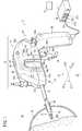
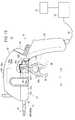
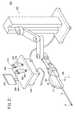
先ず、図1を参照し、本発明の一実施形態に係る医療用マニピュレータ10の全体構成について説明する。マニピュレータ10は、先端に設けられた先端動作部12で生体の一部を把持しまたは生体に触れて、所定の処置を行うための医療用の器具であり、通常、把持鉗子やニードルドライバ(持針器)等とも呼ばれる。1. First, an overall configuration of a
マニピュレータ10は、医療用器具を構成するマニピュレータ本体11と、マニピュレータ本体11にケーブル28を介して接続されたコントローラ29とを備える。マニピュレータ本体11は、ボディ21と、ボディ21から延出するシャフト18と、シャフト18の先端に設けられた先端動作部12とを有する。 The
以下の説明では、シャフト18の延在方向をZ方向と規定し、さらに、シャフト18の前方(先端側)をZ1方向、後方(根元側)をZ2方向と規定する。また、Z方向に直角な方向であって、マニピュレータ本体11を図1の姿勢にしたときのマニピュレータ本体11を基準とした左右方向をX方向とし、特に、マニピュレータ本体11の左側方向をX1方向、右側方向をX2方向と規定する。また、Z方向に直角な方向であって、マニピュレータ本体11を図1の姿勢にしたときのマニピュレータ本体11の上下方向をY方向とし、特に、上方向をY1方向、下方向をY2方向と規定する。 In the following description, the extending direction of the
なお、特に断りのない限り、これらの方向の記載はマニピュレータ本体11が基準姿勢(中立姿勢)である場合を基準として表すものとする。これらの方向は説明の便宜上のものであり、マニピュレータ本体11は任意の向きで(例えば、上下を反転させて)使用可能であることは勿論である。 Unless otherwise specified, the description of these directions is based on the case where the
マニピュレータ本体11は、人手によって把持及び操作される操作部14と、該操作部14に対して着脱自在な作業部16とを有する。操作部14は、上述したボディ21の一部を構成し、筐体を構成しZ1方向及びY2方向に略L字状に延在する左右一対の上部カバー25a、25bと、上部カバー25a、25b内に収容された駆動部30と、人手によって操作される複合入力部24(第2入力部)とを有する。 The manipulator
駆動部30は、先端動作部12の姿勢を変更させるための駆動源50として第1モータ(第1アクチュエータ)50a及び第2モータ(第2アクチュエータ)50bを有し、駆動源50の駆動力が先端動作部12に機械的に伝達されることで、先端動作部12の姿勢を変更できるように構成されている。操作部14のY1方向頂部近傍には、上部カバー25a、25bから露出してマスタスイッチ34が設けられ、マスタスイッチ34のZ1方向で視認しやすい箇所にLED35が設けられている。 The
操作部14の基端側でY2方向に延びた部分は、人手によって把持されるグリップハンドル26として構成されている。複合入力部24は、グリップハンドル26の上部の傾斜面に設けられており、左右方向への回動操作及び傾動操作を単独または複合的に行うことで、その操作に応じた信号がコントローラ29に送信され、コントローラ29が駆動部30の駆動を制御することにより、先端動作部12の姿勢変更が行われる。 A portion extending in the Y2 direction on the proximal end side of the
作業部16は、Z方向で略対称に分割された一対の下部カバー37a、37bを筐体としており、上記の先端動作部12と、この先端動作部12を先端に設けた長尺且つ中空のシャフト18と、このシャフト18の基端側が固定され、下部カバー37a、37b内に収容されたプーリボックス32と、プーリボックス32の後方に設けられ、トリガ軸39を支点としてX方向の軸心を中心に回動可能に軸支されたトリガレバー(第1入力部)36とを有する。下部カバー37a、37b、プーリボックス32及びトリガレバー36は、上述したボディ21の一部を構成する。 The working
先端動作部12は、トリガレバー36の操作に基づいて開閉動作するエンドエフェクタ300と、複合入力部24の操作に基づいてエンドエフェクタ300の姿勢を変化させる姿勢変更機構13とを有する。エンドエフェクタ300は、例えば、生体の一部や縫合用の針を把持するグリッパ、生体の一部を切断するハサミ等として、所定の開閉動作軸を基準に開閉動作可能に構成される。エンドエフェクタ300の開閉動作は、人手によるトリガレバー36の操作(押し引き操作)に基づく力が機械的に伝達されることで行われる。 The distal
トリガレバー36は、下部カバー37a、37b内のZ2方向側の端部に設けられたトリガ軸39に軸支されたアーム部36aと、このアーム部36aのY2側に設けられたトリガ操作子36bとを有する。トリガ操作子36bは、指輪部36cと、この指輪部36cのY2側に設けられた略円弧状の指掛け突起36dとを有する。 The
姿勢変更機構13は、先端を指向するロール軸(中立姿勢時にはZ軸)を基準に回転するロール動作と、Y方向のヨー軸を基準に傾動するヨー動作(傾動動作)とが可能であり、ロール動作と傾動動作とを選択的にまたは複合的に行うことが可能である。従って、先端動作部12は、エンドエフェクタ300の開閉動作、ロール動作及びヨー動作からなる3軸の動作が可能である。本実施形態の場合、エンドエフェクタ300の姿勢変更の動作(ロール動作及びヨー動作)は、複合入力部24の操作に基づいて駆動源50が駆動し、この駆動源50の駆動力が先端動作部12に機械的に伝達されることで行われる。 The
なお、機械的な伝達とは、ワイヤ、チェーン、タイミングベルト、リンク、ロッド、ギア等を介して力が伝達される方式であり、主に、動力伝達方向に非弾性な固体の機械部品を介して駆動する方式である。ワイヤやチェーン等は、張力により不可避的な多少の伸びが発生する場合があるが、これらは非弾性な固体の機械部品とする。 Mechanical transmission is a system in which force is transmitted through wires, chains, timing belts, links, rods, gears, etc., and mainly through solid mechanical parts that are inelastic in the power transmission direction. Drive system. Wires, chains, and the like may inevitably have some elongation due to tension, but these are inelastic solid mechanical parts.
このような作業部16は、操作部14に設けられた左右一対の着脱レバー40、40によって当該操作部14と連結・固定されると共に、着脱レバー40の開放操作によって操作部14から分離可能であり、特別な器具を用いることなく、手術現場で容易に交換作業等を行うことができる。 Such a working
先端動作部12及びシャフト18は細径に構成されており、患者の腹部等に装着された円筒形状のトラカール20を通して体腔22内に挿入可能であり、複合入力部24及びトリガレバー36の操作によって体腔22内で患部切除、把持、縫合及び結紮等の様々な手技を行うことができる。 The distal
コントローラ29は、マニピュレータ本体11を総合的に制御する制御部であって、グリップハンドル26の下端部から延在するケーブル28と接続される。コントローラ29の機能の一部または全部は、例えば操作部14に一体的に搭載することもできる。コントローラ29は、例えば、第1ポート27a、第2ポート27b及び第3ポート27cを備えており、3台のマニピュレータ本体11を独立的に同時に制御することができる。 The
コントローラ29には、LAN等の通信手段を介して使用履歴管理手段であるホストコンピュータ31を接続することができる。ホストコンピュータ31は、内部の図示しない記録手段に使用履歴テーブルを記録しており、コントローラ29または前記LANにより接続された複数台のコントローラ29に対して要求された個体番号(識別番号)に応じた使用履歴データを送受信し、管理する。ホストコンピュータ31は、コントローラ29から独立的な構成に限らず、コントローラ29内にその機能を設けてもよい。 The
2. マニピュレータの各構成部分の説明
2.1 エンドエフェクタ駆動機構の説明
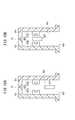
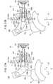
次に、主として図2及び図3を参照するとともに、補足的に図4及び図5を参照し、トリガレバー36の操作(押し引き操作)に基づいて動作するエンドエフェクタ駆動機構320について説明する。図2は、トリガレバーを押し出したときの、エンドエフェクタ駆動機構320の模式構造図である。図3は、トリガレバーを十分に引いたときの、エンドエフェクタ駆動機構320の模式構造図である。図4は、先端動作部12の斜視図である。図5は、先端動作部12の分解斜視図である。2. 2. Explanation of Each Component of Manipulator 2.1 Explanation of End Effector Drive Mechanism Next, referring mainly to FIG. 2 and FIG. 3 and supplementarily to FIG. 4 and FIG. The end
エンドエフェクタ駆動機構320の動作は、変換機構15によりエンドエフェクタ300の動作(開閉動作)に変換される。変換機構15は、エンドエフェクタ300の延在方向に進退移動可能な伝達部材152を有し、この伝達部材152が図2に示すZ1方向側の進出位置に移動すると、エンドエフェクタ300が開いた状態となり(図7参照)、伝達部材152が図3に示すZ2方向側の後退位置に移動すると、エンドエフェクタ300が閉じた状態となる(図8参照)。すなわち、伝達部材152の進退動作に伴って、エンドエフェクタ300が開閉動作するようになっている。なお、変換機構15は、伝達部材152以外にも構成部品を有するが、その詳細については後述する。 The operation of the end
エンドエフェクタ駆動機構320は、トリガレバー36をZ2方向に引いたときに伝達部材152を後退位置に向かって移動させる第1機構320aと、トリガレバー36をZ1方向に押したときに伝達部材152を進出位置に向かって移動させる第2機構320bとを有する。以下の説明では、第1機構320aにおける構成要素には符号にaを付し、第2機構320bにおける構成要素には符号にbを付して区別する。第1機構320aにおける構成要素と第2機構320bにおける構成要素で同様の機能のものについては、煩雑とならないよう、代表的に第1機構320aについてのみ説明する場合がある。 The end
第1機構320aは、トリガレバー36のアーム部36aのトリガ軸39よりも基端部側(トリガ操作子36b側)に接続された連結ロッド85と、連結ロッド85のZ1側に接続されたロッド82aと、ロッド82aのZ1側に離間して配置されたアイドルプーリ140aと、このアイドルプーリ140aのZ1側に離間して配置されたガイドプーリ142aと、このガイドプーリ142aよりもエンドエフェクタ300側に配置された受動プーリ156aと、アイドルプーリ140a、ガイドプーリ142a及び受動プーリ156aに巻き掛けられた受動ワイヤ252aとを有する。 The
シャフト18の先端部には、Z方向に離間してシャフト18内を半径方向に横断する2つの軸110、112が互いに平行に配置されており、軸110にはアイドルプーリ140aが回転可能に軸支され、軸112にはガイドプーリ142aが回転可能に軸支されている。アイドルプーリ140aは、互いに独立に回転可能な第1層アイドルプーリ232Aと第2層アイドルプーリ232Bとが同軸上に配置されて構成されている。ガイドプーリ142aは、互いに独立に回転可能な第1層ガイドプーリ236Aと第2層ガイドプーリ236Bとが同軸上に配置されて構成されている。 Two
伝達部材152には、軸112に平行なピン154が挿通されており、このピン154に受動プーリ156aが回転可能に軸支されている。このため、受動プーリ156aと伝達部材152はエンドエフェクタ300の延在方向(エンドエフェクタ300が中立姿勢のときにはZ方向)に一体的に移動可能である。ロッド82a及び受動ワイヤ252aの一部は、シャフト18内に挿通されている。ロッド82aは、例えば、十分に強く且つ細いステンレスパイプまたは中実ロッドあり、ロッド82aのZ1方向寄りの部位はシャフト18内に位置している。 A
受動ワイヤ252aは、その一部が、ロッド82aのZ1側の端部に設けられたワイヤ係合部250aに係合した環状(無端状)の可撓性部材である。受動ワイヤ252aは、ワイヤ以外にもロープ、樹脂線、ピアノ線及びチェーン等を用いることができる。ここで、環状とは広義であり、必ずしも全長にわたって可撓性部材が適用されている必要はなく、少なくとも各プーリに巻き掛けられる箇所が可撓性部材であればよく、直線部は剛体で接続されていてもよいことは勿論である。 A part of the
受動ワイヤ252aは、ロッド82aから、第1層アイドルプーリ232AのX1方向(第1の側方)を通り、X2方向(第2の側方)に向かい、第1層ガイドプーリ236AのX2方向の面を通り受動プーリ156aのX2方向の面に至る。受動ワイヤ252aは、さらに、受動プーリ156aのZ1方向の面に半周巻き掛けられてX1方向の面に至り、第2層ガイドプーリ236BのX1方向の面を通り、X2方向に向かい第2層アイドルプーリ232BのX2方向を通りワイヤ係合部250aに至る経路で配設されている。 The
アイドルプーリ140a、ガイドプーリ142a及び受動プーリ156aは略同径であり、受動ワイヤ252aがあまり屈曲しないように、レイアウト上の可能な範囲で適度に大径にしている。ワイヤ係合部250aは、受動ワイヤ252aが過度に屈曲しないように、アイドルプーリ140aよりも適度に離れた位置に設けられており、受動ワイヤ252aの両端部はワイヤ係合部250aを頂部として鋭角を形成している。アイドルプーリ140aとガイドプーリ142aとの間は狭く、例えば、受動ワイヤ252aの幅と略等しい隙間が形成されている。アイドルプーリ140a、ガイドプーリ142a及び受動プーリ156aには、受動ワイヤ252aの抜け止めのために、上面及び下面に小さいフランジを設け、または側面を凹形状にしてもよい。 The
このように構成される第1機構320aでは、トリガレバー36を引くと、アーム部36aがトリガ軸39を中心に、図3で反時計回りに回転することで、連結ロッド85を介してロッド82aがZ2方向に移動する。すると、ロッド82aに接続された受動ワイヤ252aがZ2方向に移動し、この受動ワイヤ252aのZ2方向への移動に伴って、受動プーリ156aが後退位置に向かって(図3で右方向に)移動する。このとき、伝達部材152も受動プーリ156aと一体的に移動する。 In the
また、この受動ワイヤ252aのZ2方向への移動に伴って、第1層アイドルプーリ232Aと第2層アイドルプーリ232Bが互いに反対方向に回転するとともに、第1層ガイドプーリ236Aと第2層ガイドプーリ236Bが互いに反対方向に回転する。このように、アイドルプーリ140a及びガイドプーリ142aは、それぞれ同軸上で2枚のプーリが並列する構成であることから、当接する受動ワイヤ252aの動きに従って逆方向に回転可能であり、動作がスムーズである。 As the
図2及び図3に示すように、第2機構320bは、第1機構320aに対して、基本的には、折り返しプーリ350が付加された構成である。受動プーリ156a及び受動プーリ156bは同軸構成となっている。すなわち、第2機構320bは、トリガレバー36のアーム部36aのトリガ軸39よりも先端部側(トリガ軸39を基準として指輪部36cの反対側)に接続されたワイヤ87と、ワイヤ87のZ1側に接続されたロッド82bと、ロッド82bのZ1側に離間して配置されたアイドルプーリ140bと、このアイドルプーリ140bのZ1側に離間して配置されたガイドプーリ142bと、このガイドプーリ142bよりもエンドエフェクタ300側に配置された受動プーリ156bと、この受動プーリ156bよりもエンドエフェクタ300側に離間して配置された折り返しプーリ350と、アイドルプーリ140b、ガイドプーリ142b、受動プーリ156b及び折り返しプーリ350に巻き掛けられた受動ワイヤ252bとを有する。 As shown in FIGS. 2 and 3, the
アイドルプーリ140bは、軸110により回転可能に軸支されている。アイドルプーリ140bは、互いに独立に回転可能な第1層アイドルプーリ234Aと第2層アイドルプーリ234Bとが同軸上に配置されて構成されている。ガイドプーリ142bは、軸112により回転可能に軸支されている。ガイドプーリ142bは、互いに独立に回転可能な第1層ガイドプーリ238Aと第2層ガイドプーリ238Bとが同軸上に配置されて構成されている。 The
受動プーリ156bは、後述する主軸部材144に設けられた孔144a(図5参照)内で、ピン154によって、受動プーリ156aとともに互いに独立的に同軸状に回転可能に軸支されている。このため、2つの受動プーリ156a、156b及び伝達部材152は、エンドエフェクタ300の延在方向に一体的に移動可能である。受動プーリ156bは、受動ワイヤ252bが2巻き可能な幅を有する。 The
折り返しプーリ350は、中空円筒状の先端カバー161(図4及び図5も参照)の内部に配置されたピン352により回転可能に軸支されおり、先端カバー161内での位置は固定である。折り返しプーリ350は受動ワイヤ252bが2巻き可能な幅を有する。また、折り返しプーリ350を2層化することにより、開閉動作のときに反対方向に回転できる構成となり、受動ワイヤ252bとプーリの摩擦を低減させることができる。 The folding
ロッド82b及び受動ワイヤ252bの一部は、シャフト18内に挿通されている。受動ワイヤ252bは、その一部が、ロッドのZ1側の端部に設けられたワイヤ係合部250bに係合した環状の可撓性部材である。 The
受動ワイヤ252bは、ロッド82bのワイヤ係合部250bから、第1層アイドルプーリ234AのX1方向を通り、X2方向に向かい、第1層ガイドプーリ238AのX2方向を通り受動プーリ156bのX2方向の面に至る。受動ワイヤ252bはそのままZ1方向に向かって延在し、折り返しプーリ350のX2方向の面に達し、該折り返しプーリ350のZ1方向の面に半回転巻き付けられてZ2方向に折り返す。 The
さらに、受動ワイヤ252bは、受動プーリ156bのZ2方向の面に半回転巻き付けられてX2側を通って再度折り返しプーリ350に至り、再び該折り返しプーリ350のZ1方向の面に半回転巻き付けられてZ2方向に折り返す。この後、受動ワイヤ252bは第2層ガイドプーリ238BのX1方向から第2層アイドルプーリ234BのX2方向に至り、ロッド82bのワイヤ係合部250bに至る。 Further, the
このように構成される第2機構320bでは、トリガレバー36を押し出すと、アーム部36aがトリガ軸39を中心に、図2で時計回りに回転することで、ワイヤ87を介してロッド82bがZ2方向に移動し、これに伴い、ロッド82bに接続された受動ワイヤ252bがワイヤ係合部250bの箇所でZ2方向に引っ張られて移動する。この場合、受動ワイヤ252bは、折り返しプーリ350を経由して受動ワイヤ252bに巻き掛けられているため、受動プーリ156bが図2で左方向に移動する。このとき、伝達部材152も受動プーリ156bと一体的に移動する。また、受動ワイヤ252bの移動に伴って、第1層アイドルプーリ234Aと第2層アイドルプーリ234Bが互いに反対方向に回転するとともに、第1層ガイドプーリ238Aと第2層ガイドプーリ238Bが互いに反対方向に回転する。 In the
このように、エンドエフェクタ駆動機構320により、トリガレバー36の押し引き操作が伝達部材152の進退動作に変換される。上述したように、伝達部材152が進退動作することにより、エンドエフェクタ300の開閉動作が行われる。 As described above, the end
2.2 変換機構の説明
次に、主として図4〜図8を参照し、上述したエンドエフェクタ駆動機構320の動作をエンドエフェクタ300の動作(開閉動作)に変換する変換機構15について説明する。変換機構15により開閉動作が行われるエンドエフェクタ300は、図示例ではグリッパ300Aとして構成されている。グリッパ300Aは、一対のグリッパ部材308を有し、開閉動作可能な開閉機構として構成されている。各グリッパ部材308の基端側には、レバー部310が設けられている。各レバー部310には軸孔216が形成されている。2.2 Description of Conversion Mechanism Next, the
シャフト18のZ1方向側には全体として中空円筒形の先端カバー161が配置され、この先端カバー161の先端部には一対の突出片304が設けられている。この一対の突出片304の間に、一対のグリッパ部材308のレバー部310が重なって配置されている。レバー部310の軸孔216に、先端カバー161の一対の突出片304間に固定されたピン196が挿通されることにより、各レバー部310が先端カバー161に開閉軸Ogを中心に回転可能に軸支されている。これにより、グリッパ300Aの開閉動作が可能となっている。開閉軸Ogを中心としたグリッパ部材308の可動範囲は、グリッパ300Aが例えば40°またはそれ以上開くことができるように設定されるとよい。 A hollow
変換機構15は、一対のグリッパ部材308のレバー部310にピン222を介して連結された一対のリンク部材220と、リンク部材220にピン224を介して連結された受動板158と、受動板158に対して相対回転可能に係合する上述した伝達部材152とを有する。 The
レバー部310の基端には、ピン孔218が形成され、リンク部材220の一端には、ピン孔220aが形成され、ピン222が、ピン孔218、220aに挿通されている。これにより、リンク部材220は、グリッパ部材308のレバー部310にピン222を介して回転可能に連結されている。 A
リンク部材220の他端には、ピン孔220bが形成され、ピン孔220bにピン224が挿通されている。これにより、リンク部材220は、受動板158にピン224を介して回転可能に連結されている。各リンク部材220は、平面視で、途中部分で他方のリンク部材220と交差するように、先端カバー161の軸線に対して傾斜して配設されている。 A
図5に示すように、受動板158は、Z2方向の凹部166と、該凹部166の底面に設けられた係合部168と、X方向両面にそれぞれ設けられた軸方向のリブ170と、2つのリンク孔172とを有する。係合部168は、伝達部材152の先端に設けられたきのこ状の突起174に係合する形状である。この係合により、受動板158と伝達部材152は、相対的なロール軸の回転が可能になる。 As shown in FIG. 5, the
受動板158のリブ170が、先端カバー161の内面に形成された2本の溝175に嵌ることにより、受動板158が先端カバー161の軸線方向(ロール軸Or方向)にガイドされる。受動板158の係合部168には、伝達部材152の先端に設けられた突起174が係合しているため、受動板158と伝達部材152とは、先端カバー161の内部において先端カバー161の軸線方向に一体的に移動可能となっている。 By fitting the
上述したように、トリガレバー36の押出し操作により、伝達部材152が進出方向(図7で左方方向)に移動すると、受動板158が同一方向に移動し、この受動板158の移動に伴ってリンクがレバー部310に作用し、これにより、図7に示すようにグリッパ300Aが開く。一方、トリガレバー36の引き操作により、伝達部材152が後退方向(図8で右方向)に移動すると、受動板158が同一方向に移動し、この受動板158の移動に伴ってリンク部材220がレバー部310に作用し、これにより、図8に示すようにグリッパ300Aが閉じる。 As described above, when the
グリッパ300Aには、トリガレバー36を人手によって押し出す力が、上述した第2機構320b(図3参照)によって機械的に直接伝えられることから、弾性体のような所定の力ではなく任意の強い力で開くことができる。したがって、グリッパ300Aの外側面を用いて生体組織を剥離させ、または孔部を拡開させるような手技に対して好適に用いることができる。また、グリッパ300Aの外側面に対象物が接触した場合には、受動ワイヤ252b、ロッド82b及びトリガレバー36もそれ以上Z1方向に動かなくなり、操作者はグリッパ300Aの外側面が対象物に接触したこと、及び該対象物の硬さ等を指先で知覚することができる。 Since the force that pushes the
また、図6に示すように、受動板158の係合部168には、伝達部材152の先端に設けられた突起174がロール軸Orを中心に回転可能に係合している。ここで、後述するように、先端カバー161は、シャフト18の先端部に傾動可能に軸支された主軸部材144に対してロール軸を中心に回転可能である。従って、グリッパ300A、リンク部材220、受動板158及び先端カバー161は、ロール軸Orを中心に一体的に回転可能である。 Further, as shown in FIG. 6, a
2.3 駆動部から先端動作部までの動力伝達機構の説明
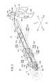
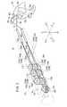
次に、駆動部30の駆動力を先端動作部12に機械的に伝達する機構について説明する。ここで、図9は、作業部16と操作部14とを分離した状態でのマニピュレータ本体11の一部断面側面図であり、図10は、作業部16の一部省略断面平面図である。プーリボックス32を構成する空洞部66には、上述したエンドエフェクタ駆動機構320の構成要素である2本のロッド82a、82bがY方向に並んで、Z方向に貫通している。2.3 Description of Power Transmission Mechanism from Driving Unit to Tip Operating Unit Next, a mechanism for mechanically transmitting the driving force of the driving
図9及び図10に示すように、プーリボックス32のZ2側には、Z方向を基準として対称な一対のピン穴84、84が形成されている。各ピン穴84、84には、作業部16と操作部14との装着時、ブラケット52の底面からY1方向に突出した一対のガイドピン86、86が挿入され、これにより、操作部14と作業部16とが位置決めされ且つ高い剛性で装着される。 As shown in FIGS. 9 and 10, a pair of pin holes 84 and 84 that are symmetrical with respect to the Z direction are formed on the Z2 side of the
駆動部30は、上述した第1及び第2モータ50a、50bと、第1及び第2モータ50a、50bを支持するブラケット52と、第1及び第2モータ50a、50bの回転方向を変換して作業部16側に伝達するギア機構部54とを有する。第1及び第2モータ50a、50bは円柱形状であり、図示しない減速機によって減速される出力軸56a、56bがブラケット52の一面を貫通し、該出力軸56a、56bに対してギア機構部54を構成する駆動傘歯車58a、58bが固定されている。第1及び第2モータ50a、50bは、例えばDCモータであり、図示しない角度センサとしてロータリエンコーダ等が設けられる。 The
ギア機構部54は、ブラケット52内の空間に設けられ、X方向に並んだ2本の駆動軸60a、60bと、各駆動軸60a、60bに固定され、駆動傘歯車58a、58bと噛み合う2つの従動傘歯車62a、62bとを有する。第1及び第2モータ50a、50bの出力軸56a、56b、駆動軸60a、60b等は図示しないベアリングによってブラケット52に軸支されている。駆動軸60a(60b)の下端側はブラケット52の下面から突出しており、その先端には、例えば断面波形六角形状で先細りのテーパ形状からなる係合凸部64a(64b)が設けられている。 The
プーリボックス32は、X方向両側が開口した空洞部66と、該空洞部66に収納されたプーリ(従動軸)70a、70b及びワイヤガイド部72a、72bとを有し、空洞部66のZ1側に貫通した孔部でシャフト18が固定・支持されている。プーリ70a、70bは、駆動軸60a、60bに対して同軸であり、その上端側には、駆動軸60a、60b側の係合凸部64a、64bと係合可能な係合凹部74a、74bが設けられている。係合凹部74a、74bは、前記係合凸部64a、64bが係合(嵌合)可能であり、例えば断面波形六角形状で奥細りのテーパ形状の凹部を有する。 The
従って、操作部14と作業部16との装着時、係合凸部64a(64b)と係合凹部74a(74b)とが係合し、これにより、駆動軸60a(60b)からの回転駆動力をプーリ70a(70b)へと伝達することができる。この際、例えば操作部14には、操作部14と作業部16の着脱を検出する着脱検出センサ(図示せず)や、駆動軸60aの位相を検出する位相検出センサ(図示せず)等を設けてもよく、さらに、係合凸部64aや係合凹部74aの係合構造は他の構造であってもよい。 Therefore, when the operating
図10に示すように、ワイヤガイド部72a、72bは、プーリ70a、70bのZ1側に配設されると共に、互いの外周面の間隔が、プーリ70a、70bの外周面間の間隔よりも狭く設定されている。ワイヤ(動力伝達部材)80a、80bは、プーリ70a、70bに巻き掛けられるとともに、ワイヤガイド部72a、72bによりガイドされて、シャフト18内に挿通されている。このようなワイヤガイド部72a、72bを用いることにより、シャフト18は、第1及び第2モータ50a、50bの径やプーリ70a、70bの軸間距離に依存することなく十分に細くすることができ、例えば、トラカール20に挿入するのに適した5mm〜10mm程度の外径に容易に設定することができる。 As shown in FIG. 10, the
図11は、駆動部30の駆動力を姿勢変更機構13(図6〜図8参照)に伝達するための機構の模式構造図である。図11に示すように、シャフト18の先端部にはガイドプーリ142a、142bを軸支する上述した軸112(図2及び図6も参照)が設けられており、ワイヤ80a、80bは、それぞれ、軸112により回転可能に軸支された歯車体(第2回転体)126、プーリ(第1回転体)130に巻き掛けられている。歯車体126及びプーリ130は、姿勢変更機構13の構成部品である。 FIG. 11 is a schematic structural diagram of a mechanism for transmitting the driving force of the driving
このような作業部16では、ワイヤ80a、80bは、それぞれプーリ70a、70b側と先端動作部12側との間で往復していることから、シャフト18の中空空間内には、延べ4本のワイヤ80a、80bと2本のロッド82a、82bとが挿通される。例えば、ロッドに代えてワイヤのみで全ての動力伝達機構を構成してもよい。ワイヤ80a、80bは、それぞれ同種または異種、同径または異径のものを用いることができ、可撓性を有する湾曲可能な線材で構成される。ワイヤ80a、80bにおいて、シャフト18内を通過する部分であって可撓性を要しない直線部分には、図示しない高剛性の補強ロッドを囲繞して、補強することもできる。 In such a working
2.4 先端動作部の説明
次に、先端動作部12の構成について、更に詳細に説明する。図5〜図8に示すように、先端動作部12は、上述したエンドエフェクタ300、変換機構15及び姿勢変更機構13を有する。姿勢変更機構13は、上述したように、エンドエフェクタ300の延在方向を指向するロール軸Or(中立姿勢時にはZ軸と一致する。)を中心に回転するロール動作と、Y方向のヨー軸Oyを中心に傾動するヨー動作(傾動動作)とが可能であり、ロール動作と傾動動作とを選択的にまたは複合的に行うことが可能である。2.4 Description of the distal end working unit Next, the configuration of the distal
姿勢変更機構13によるロール動作は、エンドエフェクタ300の延在方向のロール軸Orを中心として該エンドエフェクタ300を回転可能に設定され、例えば±180°またはそれ以上の稼動範囲を有する。また、姿勢変更機構13による傾動動作は、シャフト18の延在方向に沿う軸線に対して交差する方向に揺動するように設定され、例えば±90°またはそれ以上の可動範囲を有する。 The roll operation by the
姿勢変更機構13は、一方のワイヤ(第1伝達部材)80aを介して第1モータ50aにより回転駆動されるプーリ130が設けられシャフト18の軸線と非平行なヨー軸(傾動軸)Oyを中心に回動可能な主軸部材144と、他方のワイヤ(第2伝達部材)80bを介して第2モータ50bにより回転駆動される歯車体126と、歯車体126により駆動されエンドエフェクタ300の延在方向のロール軸Orを中心に回動可能であるように主軸部材144に支持されたギア体146(第3回転体)とを有する。 The
歯車体126及び主軸部材144は、シャフト18の先端に設けられた軸112により回転可能に支持されている。シャフト18の先端部のY方向両側には、Z1方向に突出する一対の突出片58(図5参照)が設けられており、前記の軸112は、一対の突出片58の間にY方向に沿って固定されている。歯車体126は、筒体132と、該筒体132の上部に同心状に設けられた歯車134とを有する。プーリ130は、歯車体126の筒体132と略同径で略同形状である。 The
プーリ130及び筒体132には、ワイヤ80a及び80bが所定の固定手段によって一部が固定されて巻き掛けられている。ワイヤ80a及び80bの巻き掛けられる角度は、例えば1.5回転(540°)である。プーリ130は、主軸部材144の基端部側に一体的に設けられており、この主軸部材144は、軸122によりヨー軸を中心に回動(傾動)自在に支持されている。従って、プーリ130がワイヤ80aにより回転駆動されることで、プーリ130が一体的に設けられた主軸部材144がヨー軸Oyを中心に回動する。 A part of the
主軸部材144におけるZ2方向端部には、プーリ130と歯車体126との間で、軸により回転可能に支持された2枚の補助板144b、144b(図5参照)が設けられている。補助板144b、144bは、ガイドプーリ142aのY方向上面及びガイドプーリ142bのY方向下面を保持している。また、主軸部材144におけるZ1方向端部には、補助板144b、144bからエンドエフェクタ300に向けて突出する筒部144dとを有する。主軸部材144の軸心部にはロール軸Or方向に延在する方形の孔144aが設けられており、この孔144aに、上述した変換機構15の構成部品である伝達部材152が挿入されることで、伝達部材152がロール軸方向に進退移動可能にガイドされている。 Two
図5に示すように、主軸部材144には、ピン352が挿入及び固定される径方向の軸孔354が設けられている。軸孔354は、孔144aを経由して主軸部材144の筒部144dを貫通している。また、伝達部材152には、ピン352が挿通可能な幅で軸方向に延在する長孔356が設けられている。図6に示すように、伝達部材152は、ロール軸よりY1方向にややオフセットした位置に設けられるが、先端の突起174だけは軸心に配置させるとよい。もちろん、伝達部材152はロール軸上に配置してもよい。 As shown in FIG. 5, the
ギア体146は、主軸部材144の筒部144dの外周に回転可能に支持されている。ギア体146は、ナット体148により主軸部材144に対する抜け止めがなされている。主軸部材144におけるギア体146と当接する部分には、樹脂製のスラスト軸受部材144cが設けられている。ナット体148におけるギア体146と当接する部分には、樹脂製のスラスト軸受部材148aが設けられている。スラスト軸受部材144c、148aは低摩擦材であって、当接部分の摩擦及びトルクを低減すると共に、フェイスギア165に負荷が直接的にかかることを防止する。 The
スラスト軸受部材144c、148aは、いわゆる滑り軸受であるが、転がり軸受を設けてもよい。これにより、グリッパ300Aを強く閉じた場合や開いた場合、すなわちギア体146が主軸部材144に強く当接する場合でも、ロール動作を円滑に行うことができる。 The
ギア体146は、段付き筒形状であって、Z2方向の大径部162と、Z1方向の小径部164と、大径部162のZ2方向端面に設けられたフェイスギア165とを有する。フェイスギア165は、歯車134と噛み合っている。大径部162の外周には、先端カバー161のZ2方向側の端部に設けられたネジ部に螺合するネジ部が設けられている。 The
先端カバー161は、その基端部がギア体146に外嵌されて結合(螺合、圧入等)されており、先端カバー161及びエンドエフェクタ300は、ギア体146の回転によりロール動作を行う。 The
なお、上述した変換機構15、姿勢変更機構13及び先端カバー161により、エンドエフェクタ300の開閉動作と、エンドエフェクタ300の姿勢変更とを行う複合機構部102が構成されている。 The
上記のように構成された姿勢変更機構13では、ワイヤ80b及び80aを操作することにより、プーリ130及び歯車体126を軸112に対して回転させることができる。プーリ130を回転させるとエンドエフェクタ300の傾動動作が行われる。すなわち、プーリ130が一体的に設けられた主軸部材144がヨー軸Oyを中心に回動するとともに、ギア体146、先端カバー161及びエンドエフェクタ300が主軸部材144と一体的にヨー軸Oyを中心として傾動する。 In the
一方、歯車体126を回転させると、エンドエフェクタ300のロール動作が行われる。すなわち、歯車体126によりギア体146がロール軸Orを中心に回転するとともに、先端カバー161及びエンドエフェクタ300がギア体146と一体的にロール軸Orを中心として回転する。 On the other hand, when the
2.5 複合入力部の説明
図12に示すように、先端動作部12を電気的に駆動する複合入力部24は、Z軸(Y軸)を中心としてX1及びX2方向に対称な構造であり、先端動作部12に対してロール方向(軸回転方向)及びヨー方向(左右方向)の回転指令を与える複合的な入力部である。2.5 Description of Composite Input Unit As shown in FIG. 12, the
複合入力部24は、傾斜面26aに配置されたセンサホルダ88によって支持されており、傾斜面26aのZ1側(Y1側)の回転操作部90と、そのZ2側(Y2側)に設けられた傾動操作部92と、傾動操作部92の下部側面にそれぞれ配設された3つのスイッチ操作子94a〜94cとを有する。これら回転操作部90等への入力は、センサホルダ88内に設けられたスイッチ基板(図示せず)等によってその操作量が検出され、第1及び第2モータ50a、50bがコントローラ29の制御下に適宜駆動制御される。 The
2.6 検出機構の説明
2.6.1 第1構成例に係る検出機構の説明
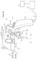
次に、図13、図14A及び図14Bを参照し、第1構成例に係る検出機構400について説明する。なお、以下の説明において、トリガレバー36の押出し位置とは、トリガレバー36を十分に押し出した位置(トリガレバー36の可動範囲のうち最もZ1方向側に回動した位置)またはその近傍位置を意味し、トリガレバー36の引き位置とは、トリガレバー36を十分に引いた位置(トリガレバー36の可動範囲のうち最もZ2方向側に回動した位置)またはその近傍位置を意味するものとする。図13では、押出し位置にあるときのトリガレバー36を実線で描いており、引き位置にあるときのトリガレバー36を二点鎖線で描いている。2.6 Description of Detection Mechanism 2.6.1 Description of Detection Mechanism According to First Configuration Example Next, the
図13に示すように、本実施の形態に係るマニピュレータ10は、第1入力部であるトリガレバー36の操作状態を検出する検出機構400をさらに備える。第1構成例に係る検出機構400は、トリガレバー36が引き位置に達したことを検出するように構成されている。すなわち、検出機構400は、エンドエフェクタ300であるグリッパ300Aが閉じた状態または殆ど閉じた状態に対応する動作位置にトリガレバー36が達したことを検出するものである。 As shown in FIG. 13, the
検出機構400は、トリガレバー36に設けられた突出部(検出用突出片)402と、操作部14に設けられた検出部404とを有する。突出部402は、トリガレバー36のアーム部36aに固定され(設けられ)、図示例では、Z2方向に突出するように設けられおり、トリガレバー36と一体的に動作する。すなわち、トリガレバー36が前後方向(Z方向)に揺動すると、突出部402も、トリガ軸39を回転支点として揺動する。 The
検出部404は、操作部14の、下部カバー37a、37bのZ2方向側の端部に対向する位置に設けられており、作業部16が操作部14に装着された状態で突出部402を検出することによりトリガレバー36が上記の引き位置に達したことを検出する。ここで、図14Aは、図13においてトリガレバー36が押出し位置にあるときの突出部402及び検出部404をZ2方向側から見た模式構成図である。図14Bは、図13においてトリガレバー36が引き位置にあるときの突出部402及び検出部404をZ2方向側から見た模式構成図である。 The
図14A及び図14Bに示すように、左右の上部カバー25a、25bの間には、突出部402が進入可能なY1方向に凹んだスペース405が設けられている。このスペース405と、上部カバー25a、25bの内部19とは、上部カバー25a、25bの壁により空間的に隔離されている。検出部404は、突出部402により押圧されてX方向に移動する作動体406と、作動体406により押圧されるタクトスイッチ408と、タクトスイッチ408が設けられるスイッチ基板409と、タクトスイッチ408を覆い弾性変形可能な柔軟材料(例えば、シリコーンゴム)からなるスイッチカバー410とを有する。 As shown in FIGS. 14A and 14B, a
作動体406は、上部カバー25bに設けられた孔412に挿通され、孔412によりX方向に移動可能にガイドされている。作動体406の内部側の外周には、係止部材411が固定されており、係止部材411により上部カバー25a、25bから作動体406がスペース405側に抜け出ることを防止している。孔412の内周面と作動体406の外周面との間には、シール部材(図示例では、Oリング)413が配置されており、シール部材413により、スペース405側から上部カバー25a、25bの内部19への液体や塵埃の侵入が防止される。スイッチ基板409は、ケーブル28を介してコントローラ29に電気的に接続されており(図13参照)、スイッチ基板409から出力される信号は、コントローラ29に送信されるようになっている。 The operating
一方、突出部402にはX方向に対して傾斜したテーパ面403が設けられており、突出部402がY1方向に移動して、テーパ面403と作動体406の一端部(X1方向の端部)が当接すると、テーパ面403により作動体406がX2方向に押圧されて移動するようになっている。なお、X方向に対して傾斜したテーパ面を作動体406の前記一端部に設けてもよく、あるいは、そのようなテーパ面を、突出部402と作動体406の両方に設けてもよい。 On the other hand, the protruding
上記のように構成された検出機構400では、トリガレバー36が押出し位置にあるときには、図14Aに示すように、突出部402が検出部404から退避しているため、検出部404が突出部402を検出しない。一方、トリガレバー36がZ2方向に回動操作され、引き位置まで達すると、図14Bに示すように、突出部402が作動体406を押圧し、X2方向に移動させるので、タクトスイッチ408がスイッチカバー410を介して押圧され、トリガレバー36が引き位置に達したことが検出される。すなわち、押圧されたことに対応する信号がタクトスイッチ408から出力され、この信号がコントローラ29に送信されることで、コントローラ29において、トリガレバー36が引き位置に達したことが認識される。 In the
検出機構400を搭載したマニピュレータ10では、トリガレバー36が引き位置に達する毎に、検出部404からの信号がコントローラ29に送信され、その回数がカウントされ、作業部16の識別番号毎の使用履歴データとして記憶される。すなわち、マニピュレータ10では、トリガレバー36の操作回数を検出・記憶でき、この操作回数を利用して、トリガレバー36自体や、トリガレバー36の操作に基づく力を機械的に伝達する機構(エンドエフェクタ駆動機構320等)の寿命予測等を行うことが可能である。 In the
なお、コントローラ29がホストコンピュータ31に接続可能である場合は、コントローラ29が、検出部404からの信号をホストコンピュータ31に転送し、ホストコンピュータ31において、トリガレバー36の操作回数を、作業部16の識別番号毎の使用履歴データとして記憶してもよい。 If the
図13に示した検出機構400は、トリガレバー36が引き位置に達したことを検出するように構成されているが、これに代えて、トリガレバー36が押出し位置に達したことを検出するように構成されてもよい。このように構成しても、上記と同様にトリガレバー36の操作回数を検出し、寿命予測等を行うことが可能である。 The
このようにマニピュレータ10では、検出機構400により、トリガレバー36の操作状態として、引き位置または押出し位置に達したことを検出するので、トリガレバー36の操作回数や使用状態の把握、分析を行うことが可能であり、このような分析を通じて、トリガレバー36自体や、トリガレバー36の操作に基づく力を機械的に伝達する機構(エンドエフェクタ駆動機構320等)の寿命予測等を行うことが可能である。 As described above, in the
また、検出機構400は、トリガレバー36が、引き位置に達したときと押出し位置に達したときの両方を検出するように構成されていてもよい。この場合、トリガレバー36が押出し位置に達したときに突出部402を検出できる位置に、上述した検出部404と同様の構成の第2の検出部を設ければよい。このような構成によれば、トリガレバー36の到達を複数の位置で検出することで、より詳細に使用状態を把握することが可能となり、寿命予測等の信頼性が向上する。 The
検出機構400によれば、トリガレバー36の動作を、突出部402を介して、操作部14に設けた検出部404に伝達するので、トリガレバー36の動作角度を検出するための電子機器を作業部16に設ける必要がない。このため、作業部16を簡便に洗浄及び滅菌することができる。 According to the
上記の検出機構400において、突出部402をトリガ操作子36bに設け、上記の検出部404をグリップハンドル26に設けてもよい。 In the
ところで、上述したように、先端動作部12は、トリガレバー36の操作に基づくエンドエフェクタ駆動機構320の動作をエンドエフェクタ300の開閉動作に変換する変換機構15と、複合入力部24の操作に基づく駆動部の駆動によりエンドエフェクタ300の姿勢を変化させる姿勢変更機構13とを有する。例えば、トリガレバー36を引き位置まで引いた状態では、図8に示すように、エンドエフェクタ駆動機構320が変換機構15をZ2方向に引っ張り、変換機構15を介して、第3回転体であるギア体146が主軸部材144に軸方向(図8で右方向)に押し付けられる。この結果、ギア体146の回転抵抗が大きくなる。また、トリガレバー36を押出し位置まで押し出した状態では、図7に示すように、エンドエフェクタ駆動機構320が変換機構15をZ1方向に押圧し、変換機構15を介して、第3回転体であるギア体146が主軸部材144に軸方向(図7で左方向)に押し付けられる。この結果、ギア体146の回転抵抗が大きくなる。 By the way, as described above, the distal
ここで、ワイヤ80bにより歯車体126(図6参照)を回転させ、歯車体126と噛み合うギア体146を回転させることでエンドエフェクタ300をロール動作させるとき、その第2モータ50bの駆動トルク(ワイヤ80bの張力)は、ロール軸Orを中心にギア体146を回転させようとするトルクだけでなく、干渉トルクとして、第1モータ50aの駆動トルク(ワイヤ80a)にも作用することになる。すなわち、ヨー軸Oyを中心に主軸部材144を回動させようとするトルクとしても作用する。そして、ヨー軸Oyを中心に主軸部材144を回動させようとするトルクは、モータ50aの駆動トルク(ワイヤ80aの張力)が受けることになる。第1モータ50aの駆動トルク(ワイヤ80aの張力)に関連する駆動系にガタがあったり、駆動系の剛性が十分でなかったりする場合(例えば、ワイヤの伸び)は、機構干渉トルクにより、先端動作部12の軌跡精度や位置決め精度の低下が懸念される。より精密な姿勢制御を行うためには、フィードフォワード制御などにより、干渉トルクを補償する制御を行うことがよい。 Here, when the
主軸部材144に対するギア体146の回転抵抗が小さいとき、すなわち、エンドエフェクタ300が何も把持していない状態では、ロール動作に起因する干渉トルクが小さいため、傾動動作の影響は少ない。ところが、主軸部材144に対するギア体146の回転抵抗が大きくなった状態、すなわち、エンドエフェクタ300が縫合用の湾曲針などを強く把持した状態で、ロール動作のためにギア体146をロール軸Orを中心に回転させると、干渉トルクが大きくなるため、傾動動作の影響が大きくなる。 When the rotational resistance of the
従って、把持している状態と把持していない状態を検出することで、主軸部材144に対するギア体146の回転抵抗、すなわち干渉トルクに応じた制御が可能となる。さらに、エンドエフェクタ300が大きく、強く開いた状態で、ロール動作のためにギア体146をロール軸Orを中心に回転させても、干渉トルクが大きくなるため、傾動動作の影響が大きくなる。 Therefore, by detecting the holding state and the non-holding state, control according to the rotational resistance of the
そこで、上述のようなロール動作に起因して傾動動作が発生する問題に対処するため、図13に示した検出機構400を搭載したマニピュレータ10では、コントローラ29は、検出機構400からの検出結果に基づくトリガレバー36の操作状態に応じて、ロール動作に起因する傾動動作の発生を防止または抑制するように、プーリ130を駆動するための第1モータ50aを制御する。 Therefore, in order to deal with the problem that the tilting operation occurs due to the roll operation as described above, in the
具体的には、コントローラ29は、ロール動作を行うための制御をする際に、トリガレバー36がその可動範囲の端部またはその近傍に位置する場合(トリガレバー36が引き位置または押し出し位置にある場合)には、プーリ130を駆動するための第1モータ50aに対して、傾動動作の発生を防止または抑制するように、ギア体146の回転抵抗の増大に対応した補償制御を行う。なお、トリガレバー36が押し出し位置に位置する場合にコントローラ29が行う上記の制御は、トリガレバー36が押出し位置に達したことを検出できるように検出機構400が構成されていることが前提となる。 Specifically, when the
トリガレバー36が引き位置または押出し位置以外の位置にあるときには、コントローラ29は、モータ50aに対してロール動作に対応した通常の制御指令を与える。これに対し、トリガレバー36が引き位置または押出し位置にあるときには、コントローラ29は、ギア体146の回転抵抗の増大に対応した補正値を通常の制御指令値に加えて第1モータ50aを制御し、傾動動作の影響を小さくし、ロール動作のみを行うようにする。もちろん、引き位置または押し位置以外の位置にあるときにも、干渉トルクはゼロではないので、対応した補正値を制御指令に加えて第1モータ50aを制御してもよい。これにより、トリガレバー36を操作することに起因してギア体146の回転抵抗が大きくなっている場合でも、ロール動作をさせる際の先端動作部12の軌跡精度や位置決め精度を効果的に向上できる。 When the
2.6.2 第2構成例に係る検出機構の説明
次に、図15A及び図15Bを参照し、第2構成例に係る検出機構420について説明する。検出機構420は、トリガレバー36に設けられた突出部422(検出用突出片)と、操作部14に設けられた検出部424とを有し、突出部422がトリガレバー36のアーム部(図13参照)に固定され(設けられ)、トリガレバー36が引き位置に達したことを検出するように構成されている点で、第1構成例に係る検出機構400と同じである。一方、検出機構420は、検出部424の構成において検出機構400と異なる。すなわち、検出機構420の検出部424は、投光器424aと受光器424bとを有するフォトセンサとして構成されている。2.6.2 Description of Detection Mechanism According to Second Configuration Example Next, the
上記のように構成された検出部424では、トリガレバー36が押出し位置にあるときには、図15Aに示すように、突出部422が検出部424から退避しているため、検出部424が突出部422を検出しない。一方、トリガレバー36が図13でZ2方向に回動操作され、引き位置まで達すると、図15Bに示すように、突出部422が投光器424aと受光器424bとの間に入り、投光器424aからの光を遮断するので、トリガレバー36が引き位置に達したことが検出される。すなわち、光が遮断されたことをコントローラ29が認識し、これにより、トリガレバー36が引き位置に達したことが検出される。 In the
なお、検出機構420は、トリガレバー36が引き位置に達したことを検出するように構成されているが、これに代えて、トリガレバー36が押出し位置に達したことを検出するように構成されてもよい。また、検出機構420は、トリガレバー36が、引き位置に達しときと押出し位置に達したときの両方を検出するように構成されてもよい。検出機構420において、突出部422をトリガ操作子36b(図13参照)に設け、検出部424をグリップハンドル26に設けてもよい。 The
第1構成例に係る検出機構400を搭載したマニピュレータ10と同様に、第2構成例に係る検出機構420を搭載したマニピュレータ10において、コントローラ29(図13参照)は、検出機構420からの検出結果に基づくトリガレバー36の操作状態に応じて、ロール動作に起因する傾動動作の発生を防止または抑制するように、モータ50aを制御する。これにより、第1構成例に係る検出機構400を搭載したマニピュレータ10と同様に、トリガレバー36を操作することに起因してギア体146の回転抵抗が大きくなっている場合でも、ロール動作をさせる際の先端動作部12の軌跡精度や位置決め精度を効果的に向上できる。 Similarly to the
2.6.3 第3構成例に係る検出機構の説明
次に、図16、図17A及び図17Bを参照し、第3構成例に係る検出機構430について説明する。図16では、押出し位置にあるときのトリガレバー36を実線で描いており、引き位置にあるときのトリガレバー36を二点鎖線で描いている。図16に示すように、第3構成例に係る検出機構430は、トリガレバー36が引き位置に達したことを検出するように構成されている。2.6.3 Description of Detection Mechanism According to Third Configuration Example Next, the
検出機構430は、トリガレバー36に設けられたカム体(検出用突出片)432と、操作部14に設けられた検出部434とを有する。カム体432は、トリガレバー36のアーム部に固定され(設けられ)、図示例では、Z2方向に突出するように設けられおり、トリガレバー36と一体的に動作する。すなわち、トリガレバー36が前後方向(Z方向)に揺動すると、カム体432も、トリガ軸39を回転支点として揺動する。検出部434は、作業部16を操作部14に装着した状態での操作部14における、カム体432に対向する位置に設けられており、作業部16が操作部14に装着された状態でカム体432を検出することによりトリガレバー36が上記の引き位置に達したことを検出する。 The
図17Aは、図16においてトリガレバー36が押出し位置にあるときの検出機構430及びその周辺の一部省略拡大構成図である。図17Bは、図16においてトリガレバー36が引き位置にあるときの検出機構430及びその周辺の一部省略拡大構成図である。図17A及び図17Bに示すように、検出部434は、カム体432により押圧されてZ方向に移動する作動ロッド436と、作動ロッド436が挿通されて作動体の移動をガイドする筒状ガイド部材442と、作動ロッド436により押圧されるタクトスイッチ438と、タクトスイッチ438が設けられたスイッチ基板439と、タクトスイッチ438を覆い弾性変形可能な柔軟材料(例えば、シリコーンゴム)からなるスイッチカバー440とを有する。 FIG. 17A is a partially omitted enlarged configuration diagram of the
作動ロッド436は、筒状ガイド部材442に挿通され一部がタクトスイッチ438側に突出する軸部436aと、この軸部436aよりもカム体432側に設けられ上部カバー25a、25bの一部である隔壁17からカム体432側に露出する頭部436bとを有する。軸部436aの外周には、フランジ部436cが設けられ、このフランジ部436cと頭部436bとの間にはシール部材(図示例では、Oリング)450が配設さている。このシール部材450により、作動ロッド436の外周と筒状ガイド部材442の内周との間が液密にシールされている。 The
筒状ガイド部材442の内部には、作動ロッド436をカム体432側に向けて弾性的に付勢するコイルバネ446が設けられている。コイルバネ446は、一端が作動ロッド436のフランジ部436cに当接し、他端が筒状ガイド部材442の内部に形成された肩部に当接している。作動ロッド436の軸部436aには、係止部材437が固定されており、係止部材437により筒状ガイド部材442から作動ロッド436がカム体432側に抜け出ることを防止している。 Inside the
筒状ガイド部材442は、中空円筒形であり、隔壁17に設けられた孔部449に挿通され、上部カバー25a、25bの内部において、筒状ガイド部材442の外周に設けられたネジ部にナット444が螺合している。これにより、筒状ガイド部材442が隔壁17に固定されている。隔壁17と筒状ガイド部材442との間には、シール部材(図示例では、Oリング)448が配設されており、シール部材448により、孔部449の内周面と筒状ガイド部材442の外周面とが液密にシールされている。 The
スイッチ基板439は、ケーブルを介してコントローラ29に電気的に接続されており、スイッチ基板439から出力される信号がコントローラ29に送信される。一方、カム体432には、作動ロッド436の頭部436bと当接するカム面432aが設けられている。また、カム体432には、Z2方向に向かうに従ってY2方向に寄るように傾斜するとともに上記のカム面432aに連なる傾斜部432bが設けられている。図17Aで、カム体432がトリガ軸39を中心に反時計回りの方向に回動すると、カム面432aにより作動ロッド436がZ2方向に押圧され、コイルバネ446の弾発力に抗して移動するようになっている。 The
上記のように構成された検出部434では、トリガレバー36が押出し位置にあるときには、図17Aに示すように、カム体432が作動ロッド436をZ2方向に押し込まないので、タクトスイッチ438は作動ロッド436に押圧されない。一方、トリガレバー36がZ2方向に回動操作され、引き位置まで達すると、図17Bに示すように、カム体432が作動ロッド436を押圧し、Z2方向に移動させるので、タクトスイッチ438がスイッチカバー440を介して押圧され、トリガレバー36が引き位置に達したことが検出される。すなわち、押圧されたことに対応する信号がタクトスイッチ438から出力され、この信号がコントローラ29に送信されることで、コントローラ29において、トリガレバー36が引き位置に達したことが認識される。 In the
第3構成例に係る検出機構430では、カム体432に適度な傾斜部432bを設けているので、トリガレバー36がどのような角度にあっても、作業部16を操作部14に装着することができる。トリガレバー36が引き位置にある場合でも、作業部16を操作部14に装着するとともに、作動ロッド436の先端部が、カム体432の傾斜部432bに接触し、Z2方向に押し込まれ、装着完了時には、トリガレバー36が引き位置にあることを検出することができる。 In the
なお、図示例の検出機構430は、トリガレバー36が引き位置に達したことを検出するように構成されているが、これに代えて、トリガレバー36が押出し位置に達したことを検出するように構成されてもよい。また、検出機構430は、トリガレバー36が、引き位置に達しときと押出し位置に達したときの両方を検出するように構成されてもよい。検出機構430において、カム体432をトリガ操作子36bに設け、上記の検出部434をグリップハンドル26に設けてもよい。 Although the
検出機構430を搭載したマニピュレータ10では、トリガレバー36が引き位置(または押出し位置)に達する毎に、検出部434からの信号がコントローラ29に送信され、その回数がカウントされ、作業部16の識別番号毎の使用履歴データとして記憶される。なお、コントローラ29がホストコンピュータ31に接続可能である場合は、コントローラ29が、検出部434からの信号をホストコンピュータ31に転送し、ホストコンピュータ31において、トリガレバー36の操作回数を、作業部16の識別番号毎の使用履歴データとして記憶してもよい。 In the
このように検出機構430により、トリガレバー36の操作状態として、引き位置または押出し位置に達したことを検出する。従って、第1構成例に係る検出機構400を備えたマニピュレータ10と同様に、トリガレバー36の操作回数等の把握、分析が可能であり、エンドエフェクタ駆動機構320等の寿命予測等を行うことが可能である。 In this manner, the
検出機構430によれば、トリガレバー36の動作を、カム体432を介して、操作部14に設けた検出部434に伝達するので、トリガレバー36の動作角度を検出するための電子機器を作業部16に設ける必要がない。このため、作業部16を簡便に洗浄及び滅菌することができる。 According to the
検出機構430において、隔壁17と筒状ガイド部材442との間、及び筒状ガイド部材442と作動ロッド436との間は、それぞれシール部材448、450でシールされているので、トリガレバー36側から上部カバー25a、25bの内部19への液体や塵埃の侵入を防止できる。 In the
第1構成例に係る検出機構400を搭載したマニピュレータ10と同様に、第3構成例に係る検出機構430を搭載したマニピュレータ10において、コントローラ29(図16参照)は、検出機構430からの検出結果に基づくトリガレバー36の操作状態に応じて、ロール動作に起因する傾動動作の発生を防止または抑制するように第1モータ50aを制御する。これにより、第1構成例に係る検出機構400を搭載したマニピュレータ10と同様に、トリガレバー36を操作することに起因してギア体146の回転抵抗が大きくなっている場合でも、ロール動作をさせる際の先端動作部12の軌跡精度や位置決め精度を効果的に向上できる。 Similarly to the
2.6.4 第4構成例に係る検出機構の説明
次に、図18A及び図18Bを参照し、第4構成例に係る検出機構430aについて説明する。検出機構430aは、トリガレバー36に設けられたカム体432(検出用突出片)と、操作部14に設けられた検出部434aとを有し、カム体432がトリガレバー36のアーム部36a(図16参照)に固定され(設けられ)、トリガレバー36が引き位置に達したことを検出するように構成されている点で、第3構成例に係る検出機構430と同じである。一方、検出機構430aの検出部434aは、タクトスイッチではなく、投光器460aと受光器460bとにより構成されるフォトセンサ460を有する。2.6.4 Description of Detection Mechanism According to Fourth Configuration Example Next, the
上記のように構成された検出部434aでは、トリガレバー36が押出し位置にあるときには、図18Aに示すように、カム体432が作動ロッド436をZ2方向に押し込まないので、作動ロッド436は投光器460aからの光を遮断しない。一方、トリガレバー36がZ2方向に回動操作され、引き位置まで達すると、図18Bに示すように、突出部が投光器460aと受光器460bとの間に入り、投光器460aからの光を遮断するので、トリガレバー36が引き位置に達したことが検出される。すなわち、光が遮断されたことをコントローラ29が認識し、これにより、トリガレバー36が引き位置に達したことが検出される。 In the
第4構成例に係る検出機構430aでは、カム体432に適度な傾斜部432bを設けているので、トリガレバー36がどのような角度にあっても、作業部16を操作部14に装着することができる。トリガレバー36が引き位置にある場合でも、作業部16を操作部14に装着するとともに、作動ロッド436の先端部が、カム体432の傾斜部432bに接触し、Z2方向に押し込まれ、装着完了時には、トリガレバー36が引き位置にあることを検出することができる。 In the
なお、図示例の検出機構430aは、トリガレバー36が引き位置に達したことを検出するように構成されているが、これに代えて、トリガレバー36が押出し位置に達したことを検出するように構成されてもよい。また、検出機構430aは、トリガレバー36が、引き位置に達しときと押出し位置に達したときの両方を検出するように構成されてもよい。検出機構430aにおいて、カム体432をトリガ操作子36bに設け、上記の検出部434aをグリップハンドル26に設けてもよい。 The
このように検出機構430aにより、トリガレバー36の操作状態として、引き位置または押出し位置に達したことを検出する。従って、第1構成例に係る検出機構400を備えたマニピュレータ10と同様に、トリガレバー36の操作回数等の把握、分析が可能であり、エンドエフェクタ駆動機構320等の寿命予測等を行うことが可能である。 In this way, the
検出機構430aによれば、トリガレバー36の動作を、カム体432を介して、操作部14に設けた検出部434aに伝達するので、トリガレバー36の動作角度を検出するための電子機器を作業部16に設ける必要がない。このため、作業部16を簡便に洗浄及び滅菌することができる。 According to the
第1構成例に係る検出機構400を搭載したマニピュレータ10と同様に、第4構成例に係る検出機構430aを搭載したマニピュレータ10において、コントローラ29(図16参照)は、検出機構430aからの検出結果に基づくトリガレバー36の操作状態に応じて、ロール動作に起因して傾動動作の発生を防止または抑制するようにモータ50aを制御する。これにより、第1構成例に係る検出機構400を搭載したマニピュレータ10と同様に、トリガレバー36を操作することに起因してギア体146の回転抵抗が大きくなっている場合でも、ロール動作をさせる際の先端動作部12の軌跡精度や位置決め精度を効果的に向上できる。 Similarly to the
上述した第1〜第4構成例に係る検出機構400、420、430、430aでは、検出部の感知手段としてタクトスイッチまたはフォトセンサを用いたが、別の感知手段として、磁気センサ、近接センサ等を用いてもよい。 In the
2.6.5 第5構成例に係る検出機構の説明
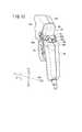
次に、図19及び図20を参照し、第5構成例に係る検出機構470について説明する。図19は、検出機構470を備えたマニピュレータ10の側面図であり、図20は、検出機構470を備えたマニピュレータ10の一部省略平面図である。第5構成例に係る検出機構470は、トリガレバー36の動作方向、つまり回動方向の位置を検出するように構成されている。図19に示すように、トリガレバー36は、最もZ1側に回動した最進出位置P1から、最もZ2側に回動した最後退位置P2までの角度θの可動範囲を有する。2.6.5 Description of Detection Mechanism According to Fifth Configuration Example Next, the
検出機構470は、トリガレバー36と一体的に動作する駆動要素472と、操作部14に設けられ作業部16が操作部14に装着された状態で駆動要素472に連動する従動要素474と、従動要素474の動作方向の位置を検出する検出部476とを有する。図示例において、駆動要素472は、トリガレバー36の回動軸心回りに周方向に延在する歯を有する第1ギア部472Aであり、従動要素474は、操作部14に回動自在に設けられ作業部16が操作部14に装着された状態で第1ギア部472Aと噛み合う第2ギア部474Aであり、検出部476は、第2ギア部474Aの回転角度を検出する回転検出器476Aである。 The
図20に示すように、第1ギア部472Aは、トリガレバー36と一体的に回転するように設けられている。すなわち、第1ギア部472Aは、トリガレバー36と一体的に回転するトリガ軸39に固定されており、トリガレバー36が前後方向(Z方向)に回動すると、第1ギア部472Aも、トリガ軸39を回転支点として回動する。なお、図示例の第1ギア部472Aでは、全周に歯が形成されているが、トリガレバー36の可動範囲の全範囲で第2ギア部474Aと噛み合うことができれば、外周の一部のみに歯が形成されてもよい。 As shown in FIG. 20, the
第2ギア部474Aは、上部カバー25bの側面に設けられている。回転検出器476Aは、上部カバー25a、25bの内部19に設けられている。第2ギア部474Aと回転検出器476Aとは、上部カバー25a、25bを貫通する軸480を介して連結されている。上部カバー25a、25bと軸との間には、シール部材(図示例では、Oリング)478が配置され、シール部材478により、外部から上部カバー25a、25bの内部19への液体や塵埃の進入が防止される。 The
回転検出器476Aとしては、例えば、ロータリエンコーダ、ポテンショメータ、レゾルバ等を用いることができる。ロータリエンコーダとしては、インクリメンタルエンコーダとアブソリュートエンコーダとがあるが、いずれを用いてもよい。回転検出器476Aは、ケーブル28を介してコントローラ29に電気的に接続されており、回転検出器476Aから出力される信号は、コントローラ29に送信されるようになっている。 For example, a rotary encoder, a potentiometer, a resolver, or the like can be used as the
上記のように構成された検出機構470では、トリガレバー36が回動操作されると、トリガレバー36に設けられた第1ギア部472Aがトリガレバー36と一体的にトリガ軸39を中心に回転する。また、第1ギア部472Aの回転に伴い、第1ギア部472Aと噛み合う第2ギア部474Aが回転し、第2ギア部474Aの回転角度が回転検出器476Aにより検出され、トリガレバー36の動作角度が検出される。すなわち、回転検出器476Aから回転角度に対応する信号が出力され、この信号がコントローラ29に送信され、コントローラ29において、回転検出器476Aからの信号に基づいてトリガレバー36の動作角度が演算される。 In the
なお、回転検出器476Aがインクリメンタルエンコーダである場合、インクリメンタルエンコーダからは回転角度の変化に応じてパルスが出力されるだけであり、トリガレバー36の絶対角度を直接検出することはできない。一方、トリガレバー36の可動範囲(最大回転角度)θは既知であるので、使用時の回転角度範囲からトリガレバー36の絶対角度を推測することが可能である。そこで、回転検出器476Aがインクリメンタルエンコーダである場合、コントローラ29は、マニピュレータ10の使用時において、トリガレバー36の可動範囲θと回転検出器476Aで検出した回転角度範囲とに基づいて、トリガレバー36の絶対角度を推定(演算)する。このように、インクリメンタルエンコーダの検出信号からトリガレバー36の絶対角度を推定することで、簡素な構成で、トリガレバー36の動作角度の検出を行うことができる。 When the
検出機構470を搭載したマニピュレータ10では、マニピュレータ10の使用中、所定のサンプリングタイム毎に、トリガレバー36の動作角度が検出され、作業部16の識別番号毎の使用履歴データとして記憶される。すなわち、マニピュレータ10では、トリガレバー36の操作回数や使用状態を検出・記憶でき、この操作回数や使用状態を利用して、トリガレバー36自体や、トリガレバー36の操作に基づく力を機械的に伝達する機構(エンドエフェクタ駆動機構320等(図2参照))の寿命予測等を行うことが可能である。特に、第5構成例に係る検出機構470によれば、トリガレバー36の動作角度を検出するので、第1〜第4構成例に係る検出機構400、420、430、430aと比較して、トリガレバー36の使用状態をより詳細に把握することが可能となり、寿命予測等の信頼性が向上する。 In the
なお、コントローラ29がホストコンピュータ31に接続可能である場合は、コントローラ29が、検出部476からの信号をホストコンピュータ31に転送し、ホストコンピュータ31において、トリガレバー36の操作回数や使用状態を、作業部16の識別番号毎の使用履歴データとして記憶してもよい。 If the
検出機構470によれば、トリガレバーの動作を、突出部402を介して、操作部14に設けた検出部404に伝達するので、トリガレバー36の動作位置を検出するための電子機器を作業部16に設ける必要がない。このため、作業部16を簡便に洗浄及び滅菌することができる。 According to the
第1構成例に係る検出機構400を搭載したマニピュレータ10と同様に、第5構成例に係る検出機構470を搭載したマニピュレータ10において、コントローラ29は、検出機構470からの検出結果に基づくトリガレバー36の操作状態に応じて、ロール動作に起因する傾動動作の発生を防止または抑制するように第1モータ50aを制御する。 Similarly to the
すなわち、コントローラ29は、検出機構470の検出結果に基づいてトリガレバー36の動作角度を監視し、ロール動作を行うための制御をする際に、トリガレバー36が押し出し位置(P1またはその近傍)または引き位置(P2またはその近傍)にある場合には、第1及び第2モータ50a、50bに対して、傾動動作の発生を防止または抑制するように、ギア体146(図6、図7等参照)の回転抵抗の増大に対応した補償制御を行う。 That is, the
これにより、第5構成例に係る検出機構470を搭載したマニピュレータ10によっても、第1構成例に係る検出機構400を搭載したマニピュレータ10と同様に、トリガレバー36を操作することに起因してギア体146の回転抵抗が大きくなっている場合でも、ロール動作をさせる際の先端動作部12の軌跡精度や位置決め精度を効果的に向上できる。 As a result, the
図19及び図20に示すように、トリガレバー36の回転軸心と、第2ギア部474Aの回転軸心とは、作業部16が操作部14に装着された状態でシャフトの延在方向(Z方向)にずれて位置することが好ましい。この構成より、作業部16を操作部14に装着する際に、作業部16に設けられた第1ギア部472Aと、操作部14に設けられた第2ギア部474Aとが、Z方向にオフセットするので、第1ギア部472Aと第2ギア部474Aとの噛み合わせ作業を円滑に行うことができる。このため、作業部16の操作部14への装着作業をスムーズに行うことができる。 As shown in FIGS. 19 and 20, the rotation axis of the
なお、トリガレバー36の回転を回転検出器476Aに伝達する機構として、磁気カップリングを採用してもよい。すなわち、トリガレバー36に設けられる駆動要素472と、操作部14に設けられる従動要素474のうち少なくとも一方を永久磁石が配置された円板として構成し、他方を永久磁石が配置された円板または強磁性体からなる円板として構成し、このように構成した駆動要素472と従動要素474とにより磁気カップリングを構成してもよい。このような磁気カップリングによっても、トリガレバー36の動作位置を検出するための電子機器を作業部16に設ける必要がないので、作業部16を簡便に洗浄及び滅菌することができる。 A magnetic coupling may be employed as a mechanism for transmitting the rotation of the
3. 手術用ロボットシステムの説明
本発明は、例えば、図21に示すような手術用ロボットシステム500に適用することもできる。手術用ロボットシステム500は、多関節型のロボットアーム502と、ロボットアームを制御するコンソール504とを有し、ロボットアーム502の先端には前記のマニピュレータ本体11と同じ機構が設けられている。ロボットアーム502の先端部508には、操作部14に代えて、内部に駆動部30を収納した基部14aが固定され、該基部14aに対して、前記の先端動作部12が設けられた作業部16が着脱可能に取り付けられる。3. Description of Surgical Robot System The present invention can also be applied to a
ロボットアーム502は、作業部16を移動させる手段であればよく、据置型に限らず、例えば自律移動型でもよい。ロボットアーム502は、独立的な6以上の関節(回転軸やスライド軸等)を有すると、作業部16の位置及び向きを任意に設定できて好適である。先端のマニピュレータ本体11を構成する基部14aは、ロボットアーム502の先端部508と一体化している。 The
コンソール504には、操作指令部としての2つのジョイスティック506と、モニタ510が設けられている。コンソール504は、テーブル型、制御盤型等の構成を採り得る。ロボットアーム502は、コンソール504の作用下によって動作し、プログラムによる自動動作や、コンソール504に設けられたジョイスティック506に倣った操作、及びこれらの複合的な動作をする構成にしてもよい。コンソール504は、前記のコントローラ29の機能を含んでいる。 The
2つのジョイスティック506により、2台のロボットアーム502を個別に操作することが可能である。なお、図21では、ロボットアーム502を1台だけ図示している。2つのジョイスティック506は、両手で操作し易い位置に設けられている。ジョイスティック506は、上下動作、左右動作、捻り動作、及び傾動動作が可能であり、これらの動作に応じてロボットアーム502を動かすことができる。ジョイスティック506はマスターアームであってもよい。 The two
ジョイスティック506には、グリップハンドル26Aと、押し引き操作されるトリガレバー36Aと、回動操作及び傾動操作される複合操作部24Aとが設けられている。トリガレバー36Aは、前記のトリガレバー36(図1参照)に代わるものであり、該トリガレバー36Aを操作することにより、図示しないモータ(人手によって操作する入力部に連動するアクチュエータ)を介して2本のロッド82a、82b(図2参照。図21中には図示せず)が進退駆動することができる。複合操作部24Aは、前記の複合入力部24(図12参照)に代わるものであり、複合操作部24Aを操作することにより、その操作内容に応じて、コンソール504により駆動部30が制御され、先端動作部12のロール動作、傾動動作またはこれらの複合動作が行われる。 The
ロボットアーム502とコンソール504との間の通信手段は、有線、無線、ネットワークまたはこれらの組合せでよい。モニタ510には、軟性鏡による画像等の情報が表示される。 Communication means between the
上記において、本発明について好適な実施の形態を挙げて説明したが、本発明は前記実施の形態に限定されるものではなく、本発明の要旨を逸脱しない範囲において、種々の改変が可能なことは言うまでもない。 In the above description, the present invention has been described with reference to preferred embodiments. However, the present invention is not limited to the above-described embodiments, and various modifications can be made without departing from the scope of the present invention. Needless to say.
Claims (10)
Translated fromJapanese前記第1入力部(36)が設けられたボディ(21)から延出するシャフト(18)と、
前記シャフト(18)の先端に設けられ、前記第1入力部(36)の操作が機械的に伝達されて動作するエンドエフェクタ(300)を有する先端動作部(12)と、
前記人手による前記第1入力部(36)に対する操作力を前記エンドエフェクタ(30)に機械的に伝達する動力伝達機構と、
前記動力伝達機構を介して前記エンドエフェクタ(300)に連結された前記第1入力部(36)の操作状態を検出する検出機構(400、420、430、430a、470)と、
を備えることを特徴とする医療用マニピュレータ(10)。A first input unit (36) operated manually,
A shaft (18) extending from a body (21) provided with the first input part (36);
A distal end working unit (12) having an end effector (300) provided at a distal end of the shaft (18) and operated by mechanically transmitting an operation of the first input unit (36);
A power transmission mechanism for mechanically transmitting an operation force to the first input unit (36) by the human hand to the end effector (30);
A detection mechanism (400, 420, 430, 430a, 470) for detecting an operation state of the first input unit (36)connected to the end effector (300) via the power transmission mechanism ;
A medical manipulator (10) comprising:
前記検出機構(400、420、430、430a)は、前記第1入力部(36)が所定位置に達したことを検出することを特徴とする医療用マニピュレータ(10)。The medical manipulator (10) according to claim 1,
The medical manipulator (10), wherein the detection mechanism (400, 420, 430, 430a) detects that the first input unit (36) has reached a predetermined position.
前記検出機構(400、420、430、430a)は、前記第1入力部(36)の可動範囲における複数の所定位置ごとに、前記第1入力部(36)が前記所定位置に達したことを検出することを特徴とする医療用マニピュレータ(10)。The medical manipulator (10) according to claim 1,
The detection mechanism (400, 420, 430, 430a) detects that the first input unit (36) has reached the predetermined position for each of a plurality of predetermined positions in the movable range of the first input unit (36). A medical manipulator (10) characterized by detecting.
前記検出機構(470)は、前記第1入力部(36)の動作方向の位置を検出することを特徴とする医療用マニピュレータ(10)。The medical manipulator (10) according to claim 1,
The medical manipulator (10), wherein the detection mechanism (470) detects a position of the first input unit (36) in an operation direction.
前記先端動作部(12)は、前記シャフト(18)に対する前記エンドエフェクタ(300)の姿勢を変化させる姿勢変更機構(13)を有し、
人手によって操作される第2入力部(24)と、人手によって把持されるグリップハンドル(26)と、前記第2入力部(24)の操作に基づいて前記姿勢変更機構(13)を駆動する駆動源(50)とを有する操作部(14)と、
前記先端動作部(12)と、前記シャフト(18)と、前記第1入力部(36)とを有して前記操作部(14)に対して着脱可能な作業部(16)と、
をさらに備え、
前記作業部(16)が前記操作部(14)に装着された状態で前記駆動源(50)の駆動力が前記姿勢変更機構(13)に機械的に伝達されることで前記エンドエフェクタ(300)の姿勢が変化し、
前記検出機構(400、420、430、430a)は、前記第1入力部(36)に設けられた検出用突出片(402、422、432)と、前記操作部(14)に設けられた検出部(404、424、434、434a)とを有し、
前記検出部(404、424、434、434a)は、前記作業部(16)が前記操作部(14)に装着された状態で前記検出用突出片(402、422、432)を検出することにより前記第1入力部(36)が前記所定位置に達したことを検出する、ことを特徴とする医療用マニピュレータ(10)。The medical manipulator (10) according to claim 2,
The distal end working unit (12) includes a posture changing mechanism (13) that changes a posture of the end effector (300) with respect to the shaft (18).
A drive for driving the posture changing mechanism (13) based on the operation of the second input unit (24) operated manually, a grip handle (26) gripped by human hands, and the second input unit (24). An operating part (14) having a source (50);
A working portion (16) having the distal end working portion (12), the shaft (18), and the first input portion (36) and detachable from the operation portion (14);
Further comprising
The driving force of the driving source (50) is mechanically transmitted to the posture changing mechanism (13) in a state where the working unit (16) is attached to the operation unit (14), thereby the end effector (300). ) ’S posture changed,
The detection mechanism (400, 420, 430, 430a) includes a detection protruding piece (402, 422, 432) provided in the first input part (36) and a detection provided in the operation part (14). Part (404, 424, 434, 434a),
The detection unit (404, 424, 434, 434a) detects the detection protruding piece (402, 422, 432) in a state where the working unit (16) is mounted on the operation unit (14). The medical manipulator (10), wherein the first input unit (36) detects that the predetermined position has been reached.
前記先端動作部(12)は、前記シャフト(18)に対する前記エンドエフェクタ(300)の姿勢を変化させる姿勢変更機構(13)を有し、
人手によって操作される第2入力部(24)と、人手によって把持されるグリップハンドル(26)と、前記第2入力部(24)の操作に基づいて前記姿勢変更機構(13)を駆動する駆動源(50)とを有する操作部(14)と、
前記先端動作部(12)と、前記シャフト(18)と、前記第1入力部(36)とを有して前記操作部(14)に対して着脱可能な作業部(16)と、
をさらに備え、
前記作業部(16)が前記操作部(14)に装着された状態で前記駆動源(50)の駆動力が前記姿勢変更機構(13)に機械的に伝達されることで前記エンドエフェクタ(300)の姿勢が変化し、
前記検出機構(470)は、
前記第1入力部(36)と一体的に動作する駆動要素(472)と、
前記操作部(14)に設けられ前記作業部(16)が前記操作部(14)に装着された状態で前記駆動要素(472)に連動する従動要素(474)と、
前記従動要素(474)の動作方向の位置を検出する検出部(476)とを有することを特徴とする医療用マニピュレータ(10)。The medical manipulator (10) according to claim 4,
The distal end working unit (12) includes a posture changing mechanism (13) that changes a posture of the end effector (300) with respect to the shaft (18).
A drive for driving the posture changing mechanism (13) based on the operation of the second input unit (24) operated manually, a grip handle (26) gripped by human hands, and the second input unit (24). An operating part (14) having a source (50);
A working portion (16) having the distal end working portion (12), the shaft (18), and the first input portion (36) and detachable from the operation portion (14);
Further comprising
The driving force of the driving source (50) is mechanically transmitted to the posture changing mechanism (13) in a state where the working unit (16) is attached to the operation unit (14), thereby the end effector (300). ) ’S posture changed,
The detection mechanism (470)
A drive element (472) operating integrally with the first input (36);
A driven element (474) that is provided in the operating section (14) and that interlocks with the driving element (472) in a state in which the working section (16) is mounted on the operating section (14);
A medical manipulator (10), comprising: a detection unit (476) for detecting a position of the driven element (474) in the operation direction.
前記第1入力部(36)は、回動操作されるトリガレバー(36)であり、
前記駆動要素(472)は、前記トリガレバー(36)の回動軸心回りに周方向に延在する歯を有する第1ギア部(472A)であり、
前記従動要素(474)は、前記操作部(14)に回動自在に設けられ前記作業部(16)が前記操作部(14)に装着された状態で前記第1ギア部(472A)と噛み合う第2ギア部(474A)であり、
前記検出部(476)は、前記第2ギア部(474A)の回転角度を検出する回転検出器(476A)であることを特徴とする医療用マニピュレータ(10)。The medical manipulator (10) according to claim 6,
The first input part (36) is a trigger lever (36) operated to rotate,
The drive element (472) is a first gear portion (472A) having teeth extending in the circumferential direction around the rotation axis of the trigger lever (36),
The driven element (474) is rotatably provided on the operation portion (14), and meshes with the first gear portion (472A) in a state where the working portion (16) is mounted on the operation portion (14). The second gear portion (474A),
The medical manipulator (10), wherein the detection unit (476) is a rotation detector (476A) that detects a rotation angle of the second gear unit (474A).
前記トリガレバー(36)の回動軸心と、前記第2ギア部(474A)の回動軸心とは、前記作業部(16)が前記操作部(14)に装着された状態で前記シャフト(18)の延在方向にずれて位置することを特徴とする医療用マニピュレータ(10)。The medical manipulator (10) according to claim 7,
The pivot axis of the trigger lever (36) and the pivot axis of the second gear part (474A) are the shafts in a state where the working part (16) is mounted on the operation part (14). A medical manipulator (10), wherein the medical manipulator (10) is shifted in the extending direction of (18).
前記先端動作部(12)は、前記第1入力部(36)の操作に基づく動作を前記エンドエフェクタ(300)の動作に変換する変換機構と、前記シャフト(18)に対する前記エンドエフェクタ(300)の姿勢を変化させる姿勢変更機構(13)とを有し、
前記姿勢変更機構(13)は、前記シャフト(18)に挿通された第1伝達部材(80a)を介して第1アクチュエータ(50a)により回転駆動される第1回転体(130)が設けられ前記シャフト(18)の軸線と非平行な傾動軸を中心に回動可能な主軸部材(144)と、前記シャフト(18)に挿通された第2伝達部材(80b)を介して第2アクチュエータ(50b)により回転駆動される第2回転体(126)と、前記第2回転体(126)により駆動され前記エンドエフェクタ(300)の延在方向のロール軸を中心に回動可能であるように前記主軸部材(144)に支持された第3回転体(146)と、を有し、
前記第1伝達部材(80a)により駆動される前記主軸部材(144)が前記傾動軸を中心に回動することで、前記エンドエフェクタ(300)の傾動動作が行われ、
前記第2伝達部材(80b)により駆動される前記第2回転体(126)が前記ロール軸を中心に前記第3回転体(146)を回転させることで、前記エンドエフェクタ(300)のロール動作が行われ、
前記医療用マニピュレータ(10)は、前記第1アクチュエータ(50a)及び前記第2アクチュエータ(50b)を制御するコントローラ(29)をさらに備え、
前記コントローラ(29)は、前記検出機構(400、420、430、430a、470)からの検出結果に基づく前記第1入力部(36)の操作状態に応じて、前記ロール動作に起因する前記傾動動作の発生を防止または抑制するように、前記第1アクチュエータ(50a)を制御することを特徴とする医療用マニピュレータ(10)。The medical manipulator (10) according to claim 1,
The distal end working unit (12) includes a conversion mechanism that converts an operation based on an operation of the first input unit (36) into an operation of the end effector (300),and the end effector (300) with respect to the shaft (18). A posture changing mechanism (13) for changing the posture of
The posture changing mechanism (13) is provided with a first rotating body (130) that is rotationally driven by a first actuator (50a) through a first transmission member (80a) inserted through the shaft (18). A main shaft member (144) that can rotate around a tilt axis that is not parallel to the axis of the shaft (18), and a second actuator (50b) via a second transmission member (80b) inserted through the shaft (18). ) And the second rotating body (126) driven to rotate by the second rotating body (126) and the end effector (300) so that the end effector (300) can be rotated around a roll axis. A third rotating body (146) supported by the main shaft member (144),
When the main shaft member (144) driven by the first transmission member (80a) rotates around the tilt shaft, the end effector (300) is tilted,
The second rotating body (126) driven by the second transmission member (80b) rotates the third rotating body (146) about the roll axis, so that the end effector (300) rolls. Is done,
The medical manipulator (10) further includes a controller (29) for controlling the first actuator (50a) and the second actuator (50b),
The controller (29) tilts due to the roll motion according to an operation state of the first input unit (36) based on a detection result from the detection mechanism (400, 420, 430, 430a, 470). The medical manipulator (10), wherein the first actuator (50a) is controlled so as to prevent or suppress the occurrence of movement.
前記エンドエフェクタ(300)は、開閉機構として構成されており、
前記コントローラ(29)は、前記ロール動作を行うための制御をする際に、前記第1入力部(36)がその可動範囲の端部またはその近傍に位置する場合には、前記第1アクチュエータ(50a)に対して、前記傾動動作の発生を防止または抑制するように、前記第3回転体(146)の回転抵抗の増大に対応した補償制御を行うことを特徴とする医療用マニピュレータ(10)。The medical manipulator (10) according to claim 9,
The end effector (300) is configured as an opening / closing mechanism,
When the controller (29) performs control for performing the roll operation, when the first input unit (36) is located at the end of the movable range or in the vicinity thereof, the first actuator ( 50a), a medical manipulator (10) characterized in that compensation control corresponding to an increase in rotational resistance of the third rotating body (146) is performed so as to prevent or suppress the occurrence of the tilting motion. .
Priority Applications (1)
| Application Number | Priority Date | Filing Date | Title |
|---|---|---|---|
| JP2012505619AJP5875973B2 (en) | 2010-03-15 | 2011-03-07 | Medical manipulator |
Applications Claiming Priority (4)
| Application Number | Priority Date | Filing Date | Title |
|---|---|---|---|
| JP2010057400 | 2010-03-15 | ||
| JP2010057400 | 2010-03-15 | ||
| PCT/JP2011/055222WO2011114924A1 (en) | 2010-03-15 | 2011-03-07 | Medical manipulator |
| JP2012505619AJP5875973B2 (en) | 2010-03-15 | 2011-03-07 | Medical manipulator |
Publications (2)
| Publication Number | Publication Date |
|---|---|
| JPWO2011114924A1 JPWO2011114924A1 (en) | 2013-06-27 |
| JP5875973B2true JP5875973B2 (en) | 2016-03-02 |
Family
ID=44649022
Family Applications (1)
| Application Number | Title | Priority Date | Filing Date |
|---|---|---|---|
| JP2012505619AExpired - Fee RelatedJP5875973B2 (en) | 2010-03-15 | 2011-03-07 | Medical manipulator |
Country Status (5)
| Country | Link |
|---|---|
| US (1) | US9788847B2 (en) |
| EP (1) | EP2548529B1 (en) |
| JP (1) | JP5875973B2 (en) |
| CN (1) | CN102802554B (en) |
| WO (1) | WO2011114924A1 (en) |
Families Citing this family (461)
| Publication number | Priority date | Publication date | Assignee | Title |
|---|---|---|---|---|
| US9060770B2 (en) | 2003-05-20 | 2015-06-23 | Ethicon Endo-Surgery, Inc. | Robotically-driven surgical instrument with E-beam driver |
| US20070084897A1 (en) | 2003-05-20 | 2007-04-19 | Shelton Frederick E Iv | Articulating surgical stapling instrument incorporating a two-piece e-beam firing mechanism |
| US8215531B2 (en) | 2004-07-28 | 2012-07-10 | Ethicon Endo-Surgery, Inc. | Surgical stapling instrument having a medical substance dispenser |
| US11890012B2 (en) | 2004-07-28 | 2024-02-06 | Cilag Gmbh International | Staple cartridge comprising cartridge body and attached support |
| US11998198B2 (en) | 2004-07-28 | 2024-06-04 | Cilag Gmbh International | Surgical stapling instrument incorporating a two-piece E-beam firing mechanism |
| US9072535B2 (en) | 2011-05-27 | 2015-07-07 | Ethicon Endo-Surgery, Inc. | Surgical stapling instruments with rotatable staple deployment arrangements |
| US10159482B2 (en) | 2005-08-31 | 2018-12-25 | Ethicon Llc | Fastener cartridge assembly comprising a fixed anvil and different staple heights |
| US7934630B2 (en) | 2005-08-31 | 2011-05-03 | Ethicon Endo-Surgery, Inc. | Staple cartridges for forming staples having differing formed staple heights |
| US11484312B2 (en) | 2005-08-31 | 2022-11-01 | Cilag Gmbh International | Staple cartridge comprising a staple driver arrangement |
| US7669746B2 (en) | 2005-08-31 | 2010-03-02 | Ethicon Endo-Surgery, Inc. | Staple cartridges for forming staples having differing formed staple heights |
| US9237891B2 (en) | 2005-08-31 | 2016-01-19 | Ethicon Endo-Surgery, Inc. | Robotically-controlled surgical stapling devices that produce formed staples having different lengths |
| US11246590B2 (en) | 2005-08-31 | 2022-02-15 | Cilag Gmbh International | Staple cartridge including staple drivers having different unfired heights |
| US20070106317A1 (en) | 2005-11-09 | 2007-05-10 | Shelton Frederick E Iv | Hydraulically and electrically actuated articulation joints for surgical instruments |
| US8186555B2 (en) | 2006-01-31 | 2012-05-29 | Ethicon Endo-Surgery, Inc. | Motor-driven surgical cutting and fastening instrument with mechanical closure system |
| US20120292367A1 (en) | 2006-01-31 | 2012-11-22 | Ethicon Endo-Surgery, Inc. | Robotically-controlled end effector |
| US20110024477A1 (en) | 2009-02-06 | 2011-02-03 | Hall Steven G | Driven Surgical Stapler Improvements |
| US11793518B2 (en) | 2006-01-31 | 2023-10-24 | Cilag Gmbh International | Powered surgical instruments with firing system lockout arrangements |
| US11278279B2 (en) | 2006-01-31 | 2022-03-22 | Cilag Gmbh International | Surgical instrument assembly |
| US7845537B2 (en) | 2006-01-31 | 2010-12-07 | Ethicon Endo-Surgery, Inc. | Surgical instrument having recording capabilities |
| US11224427B2 (en) | 2006-01-31 | 2022-01-18 | Cilag Gmbh International | Surgical stapling system including a console and retraction assembly |
| US20110295295A1 (en) | 2006-01-31 | 2011-12-01 | Ethicon Endo-Surgery, Inc. | Robotically-controlled surgical instrument having recording capabilities |
| US8820603B2 (en) | 2006-01-31 | 2014-09-02 | Ethicon Endo-Surgery, Inc. | Accessing data stored in a memory of a surgical instrument |
| US7753904B2 (en) | 2006-01-31 | 2010-07-13 | Ethicon Endo-Surgery, Inc. | Endoscopic surgical instrument with a handle that can articulate with respect to the shaft |
| US8708213B2 (en) | 2006-01-31 | 2014-04-29 | Ethicon Endo-Surgery, Inc. | Surgical instrument having a feedback system |
| US8992422B2 (en) | 2006-03-23 | 2015-03-31 | Ethicon Endo-Surgery, Inc. | Robotically-controlled endoscopic accessory channel |
| US8322455B2 (en) | 2006-06-27 | 2012-12-04 | Ethicon Endo-Surgery, Inc. | Manually driven surgical cutting and fastening instrument |
| US10568652B2 (en) | 2006-09-29 | 2020-02-25 | Ethicon Llc | Surgical staples having attached drivers of different heights and stapling instruments for deploying the same |
| US7506791B2 (en) | 2006-09-29 | 2009-03-24 | Ethicon Endo-Surgery, Inc. | Surgical stapling instrument with mechanical mechanism for limiting maximum tissue compression |
| US11980366B2 (en) | 2006-10-03 | 2024-05-14 | Cilag Gmbh International | Surgical instrument |
| US8684253B2 (en) | 2007-01-10 | 2014-04-01 | Ethicon Endo-Surgery, Inc. | Surgical instrument with wireless communication between a control unit of a robotic system and remote sensor |
| US8652120B2 (en) | 2007-01-10 | 2014-02-18 | Ethicon Endo-Surgery, Inc. | Surgical instrument with wireless communication between control unit and sensor transponders |
| US11291441B2 (en) | 2007-01-10 | 2022-04-05 | Cilag Gmbh International | Surgical instrument with wireless communication between control unit and remote sensor |
| US8632535B2 (en) | 2007-01-10 | 2014-01-21 | Ethicon Endo-Surgery, Inc. | Interlock and surgical instrument including same |
| US11039836B2 (en) | 2007-01-11 | 2021-06-22 | Cilag Gmbh International | Staple cartridge for use with a surgical stapling instrument |
| US20080169333A1 (en) | 2007-01-11 | 2008-07-17 | Shelton Frederick E | Surgical stapler end effector with tapered distal end |
| US7673782B2 (en) | 2007-03-15 | 2010-03-09 | Ethicon Endo-Surgery, Inc. | Surgical stapling instrument having a releasable buttress material |
| US8893946B2 (en) | 2007-03-28 | 2014-11-25 | Ethicon Endo-Surgery, Inc. | Laparoscopic tissue thickness and clamp load measuring devices |
| US11564682B2 (en) | 2007-06-04 | 2023-01-31 | Cilag Gmbh International | Surgical stapler device |
| US8931682B2 (en) | 2007-06-04 | 2015-01-13 | Ethicon Endo-Surgery, Inc. | Robotically-controlled shaft based rotary drive systems for surgical instruments |
| US7753245B2 (en) | 2007-06-22 | 2010-07-13 | Ethicon Endo-Surgery, Inc. | Surgical stapling instruments |
| US11849941B2 (en) | 2007-06-29 | 2023-12-26 | Cilag Gmbh International | Staple cartridge having staple cavities extending at a transverse angle relative to a longitudinal cartridge axis |
| JP5410110B2 (en) | 2008-02-14 | 2014-02-05 | エシコン・エンド−サージェリィ・インコーポレイテッド | Surgical cutting / fixing instrument with RF electrode |
| US8758391B2 (en) | 2008-02-14 | 2014-06-24 | Ethicon Endo-Surgery, Inc. | Interchangeable tools for surgical instruments |
| US7866527B2 (en) | 2008-02-14 | 2011-01-11 | Ethicon Endo-Surgery, Inc. | Surgical stapling apparatus with interlockable firing system |
| US8573465B2 (en) | 2008-02-14 | 2013-11-05 | Ethicon Endo-Surgery, Inc. | Robotically-controlled surgical end effector system with rotary actuated closure systems |
| US11986183B2 (en) | 2008-02-14 | 2024-05-21 | Cilag Gmbh International | Surgical cutting and fastening instrument comprising a plurality of sensors to measure an electrical parameter |
| US7819298B2 (en) | 2008-02-14 | 2010-10-26 | Ethicon Endo-Surgery, Inc. | Surgical stapling apparatus with control features operable with one hand |
| US8636736B2 (en) | 2008-02-14 | 2014-01-28 | Ethicon Endo-Surgery, Inc. | Motorized surgical cutting and fastening instrument |
| US9179912B2 (en) | 2008-02-14 | 2015-11-10 | Ethicon Endo-Surgery, Inc. | Robotically-controlled motorized surgical cutting and fastening instrument |
| US9585657B2 (en) | 2008-02-15 | 2017-03-07 | Ethicon Endo-Surgery, Llc | Actuator for releasing a layer of material from a surgical end effector |
| US11272927B2 (en) | 2008-02-15 | 2022-03-15 | Cilag Gmbh International | Layer arrangements for surgical staple cartridges |
| US9204923B2 (en) | 2008-07-16 | 2015-12-08 | Intuitive Surgical Operations, Inc. | Medical instrument electronically energized using drive cables |
| US9005230B2 (en) | 2008-09-23 | 2015-04-14 | Ethicon Endo-Surgery, Inc. | Motorized surgical instrument |
| US11648005B2 (en) | 2008-09-23 | 2023-05-16 | Cilag Gmbh International | Robotically-controlled motorized surgical instrument with an end effector |
| US8210411B2 (en) | 2008-09-23 | 2012-07-03 | Ethicon Endo-Surgery, Inc. | Motor-driven surgical cutting instrument |
| US9386983B2 (en) | 2008-09-23 | 2016-07-12 | Ethicon Endo-Surgery, Llc | Robotically-controlled motorized surgical instrument |
| US8608045B2 (en) | 2008-10-10 | 2013-12-17 | Ethicon Endo-Sugery, Inc. | Powered surgical cutting and stapling apparatus with manually retractable firing system |
| US8517239B2 (en) | 2009-02-05 | 2013-08-27 | Ethicon Endo-Surgery, Inc. | Surgical stapling instrument comprising a magnetic element driver |
| US8444036B2 (en) | 2009-02-06 | 2013-05-21 | Ethicon Endo-Surgery, Inc. | Motor driven surgical fastener device with mechanisms for adjusting a tissue gap within the end effector |
| RU2525225C2 (en) | 2009-02-06 | 2014-08-10 | Этикон Эндо-Серджери, Инк. | Improvement of drive surgical suturing instrument |
| US8220688B2 (en) | 2009-12-24 | 2012-07-17 | Ethicon Endo-Surgery, Inc. | Motor-driven surgical cutting instrument with electric actuator directional control assembly |
| US8851354B2 (en) | 2009-12-24 | 2014-10-07 | Ethicon Endo-Surgery, Inc. | Surgical cutting instrument that analyzes tissue thickness |
| US8783543B2 (en) | 2010-07-30 | 2014-07-22 | Ethicon Endo-Surgery, Inc. | Tissue acquisition arrangements and methods for surgical stapling devices |
| US9629814B2 (en) | 2010-09-30 | 2017-04-25 | Ethicon Endo-Surgery, Llc | Tissue thickness compensator configured to redistribute compressive forces |
| US9351730B2 (en) | 2011-04-29 | 2016-05-31 | Ethicon Endo-Surgery, Llc | Tissue thickness compensator comprising channels |
| US11298125B2 (en) | 2010-09-30 | 2022-04-12 | Cilag Gmbh International | Tissue stapler having a thickness compensator |
| US9386988B2 (en) | 2010-09-30 | 2016-07-12 | Ethicon End-Surgery, LLC | Retainer assembly including a tissue thickness compensator |
| US10945731B2 (en) | 2010-09-30 | 2021-03-16 | Ethicon Llc | Tissue thickness compensator comprising controlled release and expansion |
| US11812965B2 (en) | 2010-09-30 | 2023-11-14 | Cilag Gmbh International | Layer of material for a surgical end effector |
| US9788834B2 (en) | 2010-09-30 | 2017-10-17 | Ethicon Llc | Layer comprising deployable attachment members |
| US11925354B2 (en) | 2010-09-30 | 2024-03-12 | Cilag Gmbh International | Staple cartridge comprising staples positioned within a compressible portion thereof |
| US12213666B2 (en) | 2010-09-30 | 2025-02-04 | Cilag Gmbh International | Tissue thickness compensator comprising layers |
| US9016542B2 (en) | 2010-09-30 | 2015-04-28 | Ethicon Endo-Surgery, Inc. | Staple cartridge comprising compressible distortion resistant components |
| US9232941B2 (en) | 2010-09-30 | 2016-01-12 | Ethicon Endo-Surgery, Inc. | Tissue thickness compensator comprising a reservoir |
| US9364233B2 (en) | 2010-09-30 | 2016-06-14 | Ethicon Endo-Surgery, Llc | Tissue thickness compensators for circular surgical staplers |
| US8695866B2 (en) | 2010-10-01 | 2014-04-15 | Ethicon Endo-Surgery, Inc. | Surgical instrument having a power control circuit |
| AU2012250197B2 (en) | 2011-04-29 | 2017-08-10 | Ethicon Endo-Surgery, Inc. | Staple cartridge comprising staples positioned within a compressible portion thereof |
| US11207064B2 (en) | 2011-05-27 | 2021-12-28 | Cilag Gmbh International | Automated end effector component reloading system for use with a robotic system |
| EP2807989B1 (en) | 2011-11-23 | 2020-09-30 | Livsmed Inc. | Surgical instrument |
| KR101427330B1 (en)* | 2011-11-23 | 2014-08-06 | 주식회사 리브스메드 | Differential component |
| US9044230B2 (en) | 2012-02-13 | 2015-06-02 | Ethicon Endo-Surgery, Inc. | Surgical cutting and fastening instrument with apparatus for determining cartridge and firing motion status |
| JP6224070B2 (en) | 2012-03-28 | 2017-11-01 | エシコン・エンド−サージェリィ・インコーポレイテッドEthicon Endo−Surgery,Inc. | Retainer assembly including tissue thickness compensator |
| BR112014024098B1 (en) | 2012-03-28 | 2021-05-25 | Ethicon Endo-Surgery, Inc. | staple cartridge |
| MX358135B (en) | 2012-03-28 | 2018-08-06 | Ethicon Endo Surgery Inc | Tissue thickness compensator comprising a plurality of layers. |
| US9101358B2 (en) | 2012-06-15 | 2015-08-11 | Ethicon Endo-Surgery, Inc. | Articulatable surgical instrument comprising a firing drive |
| US20140005718A1 (en) | 2012-06-28 | 2014-01-02 | Ethicon Endo-Surgery, Inc. | Multi-functional powered surgical device with external dissection features |
| US9408606B2 (en) | 2012-06-28 | 2016-08-09 | Ethicon Endo-Surgery, Llc | Robotically powered surgical device with manually-actuatable reversing system |
| US11278284B2 (en) | 2012-06-28 | 2022-03-22 | Cilag Gmbh International | Rotary drive arrangements for surgical instruments |
| US20140001231A1 (en) | 2012-06-28 | 2014-01-02 | Ethicon Endo-Surgery, Inc. | Firing system lockout arrangements for surgical instruments |
| US12383267B2 (en) | 2012-06-28 | 2025-08-12 | Cilag Gmbh International | Robotically powered surgical device with manually-actuatable reversing system |
| US9289256B2 (en) | 2012-06-28 | 2016-03-22 | Ethicon Endo-Surgery, Llc | Surgical end effectors having angled tissue-contacting surfaces |
| US9282974B2 (en) | 2012-06-28 | 2016-03-15 | Ethicon Endo-Surgery, Llc | Empty clip cartridge lockout |
| BR112014032776B1 (en) | 2012-06-28 | 2021-09-08 | Ethicon Endo-Surgery, Inc | SURGICAL INSTRUMENT SYSTEM AND SURGICAL KIT FOR USE WITH A SURGICAL INSTRUMENT SYSTEM |
| JP6290201B2 (en) | 2012-06-28 | 2018-03-07 | エシコン・エンド−サージェリィ・インコーポレイテッドEthicon Endo−Surgery,Inc. | Lockout for empty clip cartridge |
| CN104955620B (en) | 2013-02-08 | 2016-10-05 | 奥林巴斯株式会社 | Executor |
| CN105263434B (en)* | 2013-02-20 | 2018-01-19 | 奥林巴斯株式会社 | Medical manipulator |
| RU2672520C2 (en) | 2013-03-01 | 2018-11-15 | Этикон Эндо-Серджери, Инк. | Hingedly turnable surgical instruments with conducting ways for signal transfer |
| BR112015021082B1 (en) | 2013-03-01 | 2022-05-10 | Ethicon Endo-Surgery, Inc | surgical instrument |
| US9629629B2 (en) | 2013-03-14 | 2017-04-25 | Ethicon Endo-Surgey, LLC | Control systems for surgical instruments |
| US9808244B2 (en) | 2013-03-14 | 2017-11-07 | Ethicon Llc | Sensor arrangements for absolute positioning system for surgical instruments |
| US9826976B2 (en) | 2013-04-16 | 2017-11-28 | Ethicon Llc | Motor driven surgical instruments with lockable dual drive shafts |
| BR112015026109B1 (en) | 2013-04-16 | 2022-02-22 | Ethicon Endo-Surgery, Inc | surgical instrument |
| DE102013209122A1 (en)* | 2013-05-16 | 2014-11-20 | Deutsches Zentrum für Luft- und Raumfahrt e.V. | Holding device for a surgical instrument |
| US10076348B2 (en) | 2013-08-15 | 2018-09-18 | Intuitive Surgical Operations, Inc. | Rotary input for lever actuation |
| US10550918B2 (en) | 2013-08-15 | 2020-02-04 | Intuitive Surgical Operations, Inc. | Lever actuated gimbal plate |
| MX369362B (en) | 2013-08-23 | 2019-11-06 | Ethicon Endo Surgery Llc | Firing member retraction devices for powered surgical instruments. |
| US9775609B2 (en) | 2013-08-23 | 2017-10-03 | Ethicon Llc | Tamper proof circuit for surgical instrument battery pack |
| US9962161B2 (en) | 2014-02-12 | 2018-05-08 | Ethicon Llc | Deliverable surgical instrument |
| JP6462004B2 (en) | 2014-02-24 | 2019-01-30 | エシコン エルエルシー | Fastening system with launcher lockout |
| US10013049B2 (en) | 2014-03-26 | 2018-07-03 | Ethicon Llc | Power management through sleep options of segmented circuit and wake up control |
| US20180132850A1 (en)* | 2014-03-26 | 2018-05-17 | Ethicon Llc | Surgical instrument comprising a sensor system |
| US12232723B2 (en) | 2014-03-26 | 2025-02-25 | Cilag Gmbh International | Systems and methods for controlling a segmented circuit |
| US20150272580A1 (en) | 2014-03-26 | 2015-10-01 | Ethicon Endo-Surgery, Inc. | Verification of number of battery exchanges/procedure count |
| US10004497B2 (en) | 2014-03-26 | 2018-06-26 | Ethicon Llc | Interface systems for use with surgical instruments |
| BR112016021943B1 (en) | 2014-03-26 | 2022-06-14 | Ethicon Endo-Surgery, Llc | SURGICAL INSTRUMENT FOR USE BY AN OPERATOR IN A SURGICAL PROCEDURE |
| BR112016023825B1 (en) | 2014-04-16 | 2022-08-02 | Ethicon Endo-Surgery, Llc | STAPLE CARTRIDGE FOR USE WITH A SURGICAL STAPLER AND STAPLE CARTRIDGE FOR USE WITH A SURGICAL INSTRUMENT |
| CN106456159B (en) | 2014-04-16 | 2019-03-08 | 伊西康内外科有限责任公司 | Fastener Cartridge Assembly and Nail Retainer Cover Arrangement |
| US10327764B2 (en) | 2014-09-26 | 2019-06-25 | Ethicon Llc | Method for creating a flexible staple line |
| US10470768B2 (en) | 2014-04-16 | 2019-11-12 | Ethicon Llc | Fastener cartridge including a layer attached thereto |
| US20150297225A1 (en) | 2014-04-16 | 2015-10-22 | Ethicon Endo-Surgery, Inc. | Fastener cartridges including extensions having different configurations |
| CN106456176B (en) | 2014-04-16 | 2019-06-28 | 伊西康内外科有限责任公司 | Fastener Cartridge Including Extensions With Different Configurations |
| KR101584766B1 (en) | 2014-04-24 | 2016-01-12 | 주식회사 리브스메드 | Surgical instrument |
| US11311294B2 (en) | 2014-09-05 | 2022-04-26 | Cilag Gmbh International | Powered medical device including measurement of closure state of jaws |
| US10135242B2 (en) | 2014-09-05 | 2018-11-20 | Ethicon Llc | Smart cartridge wake up operation and data retention |
| BR112017004361B1 (en) | 2014-09-05 | 2023-04-11 | Ethicon Llc | ELECTRONIC SYSTEM FOR A SURGICAL INSTRUMENT |
| US10105142B2 (en) | 2014-09-18 | 2018-10-23 | Ethicon Llc | Surgical stapler with plurality of cutting elements |
| CN107427300B (en) | 2014-09-26 | 2020-12-04 | 伊西康有限责任公司 | Surgical suture buttresses and auxiliary materials |
| US11523821B2 (en) | 2014-09-26 | 2022-12-13 | Cilag Gmbh International | Method for creating a flexible staple line |
| US10709467B2 (en) | 2014-10-02 | 2020-07-14 | Livsmed Inc. | Surgical instrument |
| US10076325B2 (en) | 2014-10-13 | 2018-09-18 | Ethicon Llc | Surgical stapling apparatus comprising a tissue stop |
| US9924944B2 (en) | 2014-10-16 | 2018-03-27 | Ethicon Llc | Staple cartridge comprising an adjunct material |
| US10517594B2 (en) | 2014-10-29 | 2019-12-31 | Ethicon Llc | Cartridge assemblies for surgical staplers |
| US11141153B2 (en) | 2014-10-29 | 2021-10-12 | Cilag Gmbh International | Staple cartridges comprising driver arrangements |
| US9844376B2 (en) | 2014-11-06 | 2017-12-19 | Ethicon Llc | Staple cartridge comprising a releasable adjunct material |
| US10736636B2 (en) | 2014-12-10 | 2020-08-11 | Ethicon Llc | Articulatable surgical instrument system |
| US9943309B2 (en) | 2014-12-18 | 2018-04-17 | Ethicon Llc | Surgical instruments with articulatable end effectors and movable firing beam support arrangements |
| US10188385B2 (en) | 2014-12-18 | 2019-01-29 | Ethicon Llc | Surgical instrument system comprising lockable systems |
| MX389118B (en) | 2014-12-18 | 2025-03-20 | Ethicon Llc | SURGICAL INSTRUMENT WITH AN ANVIL THAT CAN BE SELECTIVELY MOVED ON A DISCRETE, NON-MOBILE AXIS RELATIVE TO A STAPLE CARTRIDGE. |
| US9987000B2 (en) | 2014-12-18 | 2018-06-05 | Ethicon Llc | Surgical instrument assembly comprising a flexible articulation system |
| US9844375B2 (en) | 2014-12-18 | 2017-12-19 | Ethicon Llc | Drive arrangements for articulatable surgical instruments |
| US9844374B2 (en) | 2014-12-18 | 2017-12-19 | Ethicon Llc | Surgical instrument systems comprising an articulatable end effector and means for adjusting the firing stroke of a firing member |
| US10085748B2 (en) | 2014-12-18 | 2018-10-02 | Ethicon Llc | Locking arrangements for detachable shaft assemblies with articulatable surgical end effectors |
| US11344381B2 (en) | 2015-02-17 | 2022-05-31 | Livsmed Inc. | Instrument for surgery |
| KR102153407B1 (en) | 2015-02-17 | 2020-09-08 | 주식회사 리브스메드 | Surgical instrument |
| US11896336B2 (en) | 2015-02-17 | 2024-02-13 | Livsmed Inc. | Instrument for surgery |
| US10180463B2 (en) | 2015-02-27 | 2019-01-15 | Ethicon Llc | Surgical apparatus configured to assess whether a performance parameter of the surgical apparatus is within an acceptable performance band |
| US10159483B2 (en) | 2015-02-27 | 2018-12-25 | Ethicon Llc | Surgical apparatus configured to track an end-of-life parameter |
| US11154301B2 (en) | 2015-02-27 | 2021-10-26 | Cilag Gmbh International | Modular stapling assembly |
| US10245033B2 (en) | 2015-03-06 | 2019-04-02 | Ethicon Llc | Surgical instrument comprising a lockable battery housing |
| US10548504B2 (en) | 2015-03-06 | 2020-02-04 | Ethicon Llc | Overlaid multi sensor radio frequency (RF) electrode system to measure tissue compression |
| US10441279B2 (en) | 2015-03-06 | 2019-10-15 | Ethicon Llc | Multiple level thresholds to modify operation of powered surgical instruments |
| US9808246B2 (en) | 2015-03-06 | 2017-11-07 | Ethicon Endo-Surgery, Llc | Method of operating a powered surgical instrument |
| US10687806B2 (en) | 2015-03-06 | 2020-06-23 | Ethicon Llc | Adaptive tissue compression techniques to adjust closure rates for multiple tissue types |
| US10617412B2 (en) | 2015-03-06 | 2020-04-14 | Ethicon Llc | System for detecting the mis-insertion of a staple cartridge into a surgical stapler |
| US9901342B2 (en) | 2015-03-06 | 2018-02-27 | Ethicon Endo-Surgery, Llc | Signal and power communication system positioned on a rotatable shaft |
| JP2020121162A (en) | 2015-03-06 | 2020-08-13 | エシコン エルエルシーEthicon LLC | Time dependent evaluation of sensor data to determine stability element, creep element and viscoelastic element of measurement |
| US9924961B2 (en) | 2015-03-06 | 2018-03-27 | Ethicon Endo-Surgery, Llc | Interactive feedback system for powered surgical instruments |
| US9993248B2 (en) | 2015-03-06 | 2018-06-12 | Ethicon Endo-Surgery, Llc | Smart sensors with local signal processing |
| US10433844B2 (en) | 2015-03-31 | 2019-10-08 | Ethicon Llc | Surgical instrument with selectively disengageable threaded drive systems |
| WO2016209891A1 (en)* | 2015-06-23 | 2016-12-29 | Covidien Lp | Robotic surgical assemblies |
| US10835249B2 (en) | 2015-08-17 | 2020-11-17 | Ethicon Llc | Implantable layers for a surgical instrument |
| US10327769B2 (en) | 2015-09-23 | 2019-06-25 | Ethicon Llc | Surgical stapler having motor control based on a drive system component |
| US10105139B2 (en) | 2015-09-23 | 2018-10-23 | Ethicon Llc | Surgical stapler having downstream current-based motor control |
| US10238386B2 (en) | 2015-09-23 | 2019-03-26 | Ethicon Llc | Surgical stapler having motor control based on an electrical parameter related to a motor current |
| US10363036B2 (en) | 2015-09-23 | 2019-07-30 | Ethicon Llc | Surgical stapler having force-based motor control |
| US10299878B2 (en) | 2015-09-25 | 2019-05-28 | Ethicon Llc | Implantable adjunct systems for determining adjunct skew |
| US10980539B2 (en) | 2015-09-30 | 2021-04-20 | Ethicon Llc | Implantable adjunct comprising bonded layers |
| US10433846B2 (en) | 2015-09-30 | 2019-10-08 | Ethicon Llc | Compressible adjunct with crossing spacer fibers |
| US10478188B2 (en) | 2015-09-30 | 2019-11-19 | Ethicon Llc | Implantable layer comprising a constricted configuration |
| US11890015B2 (en) | 2015-09-30 | 2024-02-06 | Cilag Gmbh International | Compressible adjunct with crossing spacer fibers |
| DE102015117213B4 (en)* | 2015-10-08 | 2020-10-29 | Kastanienbaum GmbH | Robotic arm |
| ITUB20154977A1 (en) | 2015-10-16 | 2017-04-16 | Medical Microinstruments S R L | Medical instrument and method of manufacture of said medical instrument |
| US10413316B2 (en) | 2015-11-17 | 2019-09-17 | Covidien Lp | Articulating ultrasonic surgical instruments and systems |
| US10368865B2 (en) | 2015-12-30 | 2019-08-06 | Ethicon Llc | Mechanisms for compensating for drivetrain failure in powered surgical instruments |
| US10265068B2 (en) | 2015-12-30 | 2019-04-23 | Ethicon Llc | Surgical instruments with separable motors and motor control circuits |
| US10292704B2 (en) | 2015-12-30 | 2019-05-21 | Ethicon Llc | Mechanisms for compensating for battery pack failure in powered surgical instruments |
| US10413291B2 (en) | 2016-02-09 | 2019-09-17 | Ethicon Llc | Surgical instrument articulation mechanism with slotted secondary constraint |
| BR112018016098B1 (en) | 2016-02-09 | 2023-02-23 | Ethicon Llc | SURGICAL INSTRUMENT |
| US11213293B2 (en) | 2016-02-09 | 2022-01-04 | Cilag Gmbh International | Articulatable surgical instruments with single articulation link arrangements |
| US10258331B2 (en) | 2016-02-12 | 2019-04-16 | Ethicon Llc | Mechanisms for compensating for drivetrain failure in powered surgical instruments |
| US10448948B2 (en) | 2016-02-12 | 2019-10-22 | Ethicon Llc | Mechanisms for compensating for drivetrain failure in powered surgical instruments |
| US11224426B2 (en) | 2016-02-12 | 2022-01-18 | Cilag Gmbh International | Mechanisms for compensating for drivetrain failure in powered surgical instruments |
| US10617413B2 (en) | 2016-04-01 | 2020-04-14 | Ethicon Llc | Closure system arrangements for surgical cutting and stapling devices with separate and distinct firing shafts |
| US10413297B2 (en) | 2016-04-01 | 2019-09-17 | Ethicon Llc | Surgical stapling system configured to apply annular rows of staples having different heights |
| US10405859B2 (en) | 2016-04-15 | 2019-09-10 | Ethicon Llc | Surgical instrument with adjustable stop/start control during a firing motion |
| US10335145B2 (en) | 2016-04-15 | 2019-07-02 | Ethicon Llc | Modular surgical instrument with configurable operating mode |
| US11607239B2 (en) | 2016-04-15 | 2023-03-21 | Cilag Gmbh International | Systems and methods for controlling a surgical stapling and cutting instrument |
| US10828028B2 (en) | 2016-04-15 | 2020-11-10 | Ethicon Llc | Surgical instrument with multiple program responses during a firing motion |
| US10492783B2 (en) | 2016-04-15 | 2019-12-03 | Ethicon, Llc | Surgical instrument with improved stop/start control during a firing motion |
| US11179150B2 (en) | 2016-04-15 | 2021-11-23 | Cilag Gmbh International | Systems and methods for controlling a surgical stapling and cutting instrument |
| US10456137B2 (en) | 2016-04-15 | 2019-10-29 | Ethicon Llc | Staple formation detection mechanisms |
| US10357247B2 (en) | 2016-04-15 | 2019-07-23 | Ethicon Llc | Surgical instrument with multiple program responses during a firing motion |
| US10426467B2 (en) | 2016-04-15 | 2019-10-01 | Ethicon Llc | Surgical instrument with detection sensors |
| US20170296173A1 (en) | 2016-04-18 | 2017-10-19 | Ethicon Endo-Surgery, Llc | Method for operating a surgical instrument |
| US11317917B2 (en) | 2016-04-18 | 2022-05-03 | Cilag Gmbh International | Surgical stapling system comprising a lockable firing assembly |
| US10363037B2 (en) | 2016-04-18 | 2019-07-30 | Ethicon Llc | Surgical instrument system comprising a magnetic lockout |
| EP3484397B1 (en) | 2016-07-14 | 2024-07-24 | Intuitive Surgical Operations, Inc. | Multi-cable medical instrument |
| WO2018013298A1 (en) | 2016-07-14 | 2018-01-18 | Intuitive Surgical Operations, Inc. | Geared grip actuation for medical instruments |
| US10500000B2 (en)* | 2016-08-16 | 2019-12-10 | Ethicon Llc | Surgical tool with manual control of end effector jaws |
| WO2018094191A1 (en) | 2016-11-21 | 2018-05-24 | Intuitive Surgical Operations, Inc. | Cable length conserving medical instrument |
| US10980536B2 (en) | 2016-12-21 | 2021-04-20 | Ethicon Llc | No-cartridge and spent cartridge lockout arrangements for surgical staplers |
| US10568625B2 (en) | 2016-12-21 | 2020-02-25 | Ethicon Llc | Staple cartridges and arrangements of staples and staple cavities therein |
| US10426471B2 (en) | 2016-12-21 | 2019-10-01 | Ethicon Llc | Surgical instrument with multiple failure response modes |
| CN110087565A (en) | 2016-12-21 | 2019-08-02 | 爱惜康有限责任公司 | Surgical stapling system |
| US20180168625A1 (en) | 2016-12-21 | 2018-06-21 | Ethicon Endo-Surgery, Llc | Surgical stapling instruments with smart staple cartridges |
| JP2020501815A (en) | 2016-12-21 | 2020-01-23 | エシコン エルエルシーEthicon LLC | Surgical stapling system |
| US11134942B2 (en) | 2016-12-21 | 2021-10-05 | Cilag Gmbh International | Surgical stapling instruments and staple-forming anvils |
| US10485543B2 (en) | 2016-12-21 | 2019-11-26 | Ethicon Llc | Anvil having a knife slot width |
| US10813638B2 (en) | 2016-12-21 | 2020-10-27 | Ethicon Llc | Surgical end effectors with expandable tissue stop arrangements |
| US11419606B2 (en) | 2016-12-21 | 2022-08-23 | Cilag Gmbh International | Shaft assembly comprising a clutch configured to adapt the output of a rotary firing member to two different systems |
| JP6983893B2 (en) | 2016-12-21 | 2021-12-17 | エシコン エルエルシーEthicon LLC | Lockout configuration for surgical end effectors and replaceable tool assemblies |
| US10542982B2 (en) | 2016-12-21 | 2020-01-28 | Ethicon Llc | Shaft assembly comprising first and second articulation lockouts |
| US10898186B2 (en) | 2016-12-21 | 2021-01-26 | Ethicon Llc | Staple forming pocket arrangements comprising primary sidewalls and pocket sidewalls |
| US20180168615A1 (en) | 2016-12-21 | 2018-06-21 | Ethicon Endo-Surgery, Llc | Method of deforming staples from two different types of staple cartridges with the same surgical stapling instrument |
| US11090048B2 (en) | 2016-12-21 | 2021-08-17 | Cilag Gmbh International | Method for resetting a fuse of a surgical instrument shaft |
| JP7010956B2 (en) | 2016-12-21 | 2022-01-26 | エシコン エルエルシー | How to staple tissue |
| US10582928B2 (en) | 2016-12-21 | 2020-03-10 | Ethicon Llc | Articulation lock arrangements for locking an end effector in an articulated position in response to actuation of a jaw closure system |
| US10695055B2 (en) | 2016-12-21 | 2020-06-30 | Ethicon Llc | Firing assembly comprising a lockout |
| MX2019007295A (en) | 2016-12-21 | 2019-10-15 | Ethicon Llc | Surgical instrument system comprising an end effector lockout and a firing assembly lockout. |
| JP7010957B2 (en) | 2016-12-21 | 2022-01-26 | エシコン エルエルシー | Shaft assembly with lockout |
| US10973516B2 (en) | 2016-12-21 | 2021-04-13 | Ethicon Llc | Surgical end effectors and adaptable firing members therefor |
| US10758229B2 (en) | 2016-12-21 | 2020-09-01 | Ethicon Llc | Surgical instrument comprising improved jaw control |
| US10357321B2 (en) | 2017-02-24 | 2019-07-23 | Intuitive Surgical Operations, Inc. | Splayed cable guide for a medical instrument |
| CN106959727B (en)* | 2017-03-10 | 2018-07-20 | 国家海洋局第二海洋研究所 | A kind of control stick adjustment equipment |
| US10307170B2 (en) | 2017-06-20 | 2019-06-04 | Ethicon Llc | Method for closed loop control of motor velocity of a surgical stapling and cutting instrument |
| US10813639B2 (en) | 2017-06-20 | 2020-10-27 | Ethicon Llc | Closed loop feedback control of motor velocity of a surgical stapling and cutting instrument based on system conditions |
| US10368864B2 (en) | 2017-06-20 | 2019-08-06 | Ethicon Llc | Systems and methods for controlling displaying motor velocity for a surgical instrument |
| US10980537B2 (en) | 2017-06-20 | 2021-04-20 | Ethicon Llc | Closed loop feedback control of motor velocity of a surgical stapling and cutting instrument based on measured time over a specified number of shaft rotations |
| US11382638B2 (en) | 2017-06-20 | 2022-07-12 | Cilag Gmbh International | Closed loop feedback control of motor velocity of a surgical stapling and cutting instrument based on measured time over a specified displacement distance |
| USD879809S1 (en) | 2017-06-20 | 2020-03-31 | Ethicon Llc | Display panel with changeable graphical user interface |
| US10888321B2 (en) | 2017-06-20 | 2021-01-12 | Ethicon Llc | Systems and methods for controlling velocity of a displacement member of a surgical stapling and cutting instrument |
| US11517325B2 (en) | 2017-06-20 | 2022-12-06 | Cilag Gmbh International | Closed loop feedback control of motor velocity of a surgical stapling and cutting instrument based on measured displacement distance traveled over a specified time interval |
| US10390841B2 (en) | 2017-06-20 | 2019-08-27 | Ethicon Llc | Control of motor velocity of a surgical stapling and cutting instrument based on angle of articulation |
| US10646220B2 (en) | 2017-06-20 | 2020-05-12 | Ethicon Llc | Systems and methods for controlling displacement member velocity for a surgical instrument |
| US10881399B2 (en) | 2017-06-20 | 2021-01-05 | Ethicon Llc | Techniques for adaptive control of motor velocity of a surgical stapling and cutting instrument |
| USD890784S1 (en) | 2017-06-20 | 2020-07-21 | Ethicon Llc | Display panel with changeable graphical user interface |
| US10881396B2 (en) | 2017-06-20 | 2021-01-05 | Ethicon Llc | Surgical instrument with variable duration trigger arrangement |
| US10779820B2 (en) | 2017-06-20 | 2020-09-22 | Ethicon Llc | Systems and methods for controlling motor speed according to user input for a surgical instrument |
| US11090046B2 (en) | 2017-06-20 | 2021-08-17 | Cilag Gmbh International | Systems and methods for controlling displacement member motion of a surgical stapling and cutting instrument |
| US10327767B2 (en) | 2017-06-20 | 2019-06-25 | Ethicon Llc | Control of motor velocity of a surgical stapling and cutting instrument based on angle of articulation |
| USD879808S1 (en) | 2017-06-20 | 2020-03-31 | Ethicon Llc | Display panel with graphical user interface |
| US10624633B2 (en) | 2017-06-20 | 2020-04-21 | Ethicon Llc | Systems and methods for controlling motor velocity of a surgical stapling and cutting instrument |
| US11653914B2 (en) | 2017-06-20 | 2023-05-23 | Cilag Gmbh International | Systems and methods for controlling motor velocity of a surgical stapling and cutting instrument according to articulation angle of end effector |
| US11071554B2 (en) | 2017-06-20 | 2021-07-27 | Cilag Gmbh International | Closed loop feedback control of motor velocity of a surgical stapling and cutting instrument based on magnitude of velocity error measurements |
| US11090049B2 (en) | 2017-06-27 | 2021-08-17 | Cilag Gmbh International | Staple forming pocket arrangements |
| US11266405B2 (en) | 2017-06-27 | 2022-03-08 | Cilag Gmbh International | Surgical anvil manufacturing methods |
| US10993716B2 (en) | 2017-06-27 | 2021-05-04 | Ethicon Llc | Surgical anvil arrangements |
| US10772629B2 (en) | 2017-06-27 | 2020-09-15 | Ethicon Llc | Surgical anvil arrangements |
| US10856869B2 (en) | 2017-06-27 | 2020-12-08 | Ethicon Llc | Surgical anvil arrangements |
| US11324503B2 (en) | 2017-06-27 | 2022-05-10 | Cilag Gmbh International | Surgical firing member arrangements |
| US11246592B2 (en) | 2017-06-28 | 2022-02-15 | Cilag Gmbh International | Surgical instrument comprising an articulation system lockable to a frame |
| US10903685B2 (en) | 2017-06-28 | 2021-01-26 | Ethicon Llc | Surgical shaft assemblies with slip ring assemblies forming capacitive channels |
| USD851762S1 (en) | 2017-06-28 | 2019-06-18 | Ethicon Llc | Anvil |
| US11259805B2 (en) | 2017-06-28 | 2022-03-01 | Cilag Gmbh International | Surgical instrument comprising firing member supports |
| US10716614B2 (en) | 2017-06-28 | 2020-07-21 | Ethicon Llc | Surgical shaft assemblies with slip ring assemblies with increased contact pressure |
| USD906355S1 (en) | 2017-06-28 | 2020-12-29 | Ethicon Llc | Display screen or portion thereof with a graphical user interface for a surgical instrument |
| USD854151S1 (en) | 2017-06-28 | 2019-07-16 | Ethicon Llc | Surgical instrument shaft |
| US10758232B2 (en) | 2017-06-28 | 2020-09-01 | Ethicon Llc | Surgical instrument with positive jaw opening features |
| US11564686B2 (en) | 2017-06-28 | 2023-01-31 | Cilag Gmbh International | Surgical shaft assemblies with flexible interfaces |
| US11484310B2 (en) | 2017-06-28 | 2022-11-01 | Cilag Gmbh International | Surgical instrument comprising a shaft including a closure tube profile |
| USD869655S1 (en) | 2017-06-28 | 2019-12-10 | Ethicon Llc | Surgical fastener cartridge |
| US10765427B2 (en) | 2017-06-28 | 2020-09-08 | Ethicon Llc | Method for articulating a surgical instrument |
| US10211586B2 (en) | 2017-06-28 | 2019-02-19 | Ethicon Llc | Surgical shaft assemblies with watertight housings |
| EP3420947B1 (en) | 2017-06-28 | 2022-05-25 | Cilag GmbH International | Surgical instrument comprising selectively actuatable rotatable couplers |
| US11007022B2 (en) | 2017-06-29 | 2021-05-18 | Ethicon Llc | Closed loop velocity control techniques based on sensed tissue parameters for robotic surgical instrument |
| US10932772B2 (en) | 2017-06-29 | 2021-03-02 | Ethicon Llc | Methods for closed loop velocity control for robotic surgical instrument |
| US10398434B2 (en) | 2017-06-29 | 2019-09-03 | Ethicon Llc | Closed loop velocity control of closure member for robotic surgical instrument |
| US10258418B2 (en) | 2017-06-29 | 2019-04-16 | Ethicon Llc | System for controlling articulation forces |
| US10898183B2 (en) | 2017-06-29 | 2021-01-26 | Ethicon Llc | Robotic surgical instrument with closed loop feedback techniques for advancement of closure member during firing |
| US11471155B2 (en) | 2017-08-03 | 2022-10-18 | Cilag Gmbh International | Surgical system bailout |
| US11304695B2 (en) | 2017-08-03 | 2022-04-19 | Cilag Gmbh International | Surgical system shaft interconnection |
| US11974742B2 (en) | 2017-08-03 | 2024-05-07 | Cilag Gmbh International | Surgical system comprising an articulation bailout |
| US11944300B2 (en) | 2017-08-03 | 2024-04-02 | Cilag Gmbh International | Method for operating a surgical system bailout |
| KR102607089B1 (en) | 2017-08-10 | 2023-11-29 | 인튜어티브 서지컬 오퍼레이션즈 인코포레이티드 | Increased usable instrument life in telesurgical systems |
| US12029512B2 (en) | 2017-08-10 | 2024-07-09 | Intuitive Surgical Operations, Inc. | Increased usable instrument life in telesurgical systems |
| JP7013766B2 (en)* | 2017-09-22 | 2022-02-01 | セイコーエプソン株式会社 | Robot control device, robot system, and control method |
| USD917500S1 (en) | 2017-09-29 | 2021-04-27 | Ethicon Llc | Display screen or portion thereof with graphical user interface |
| US11399829B2 (en) | 2017-09-29 | 2022-08-02 | Cilag Gmbh International | Systems and methods of initiating a power shutdown mode for a surgical instrument |
| US10796471B2 (en) | 2017-09-29 | 2020-10-06 | Ethicon Llc | Systems and methods of displaying a knife position for a surgical instrument |
| US10765429B2 (en) | 2017-09-29 | 2020-09-08 | Ethicon Llc | Systems and methods for providing alerts according to the operational state of a surgical instrument |
| USD907647S1 (en) | 2017-09-29 | 2021-01-12 | Ethicon Llc | Display screen or portion thereof with animated graphical user interface |
| US10743872B2 (en) | 2017-09-29 | 2020-08-18 | Ethicon Llc | System and methods for controlling a display of a surgical instrument |
| US10729501B2 (en) | 2017-09-29 | 2020-08-04 | Ethicon Llc | Systems and methods for language selection of a surgical instrument |
| USD907648S1 (en) | 2017-09-29 | 2021-01-12 | Ethicon Llc | Display screen or portion thereof with animated graphical user interface |
| US10786320B2 (en)* | 2017-10-26 | 2020-09-29 | Ethicon Llc | Cable driven motion systems for robotic surgical tools |
| US11134944B2 (en) | 2017-10-30 | 2021-10-05 | Cilag Gmbh International | Surgical stapler knife motion controls |
| US11090075B2 (en) | 2017-10-30 | 2021-08-17 | Cilag Gmbh International | Articulation features for surgical end effector |
| US10779903B2 (en) | 2017-10-31 | 2020-09-22 | Ethicon Llc | Positive shaft rotation lock activated by jaw closure |
| US10842490B2 (en) | 2017-10-31 | 2020-11-24 | Ethicon Llc | Cartridge body design with force reduction based on firing completion |
| CN107837067B (en)* | 2017-11-06 | 2018-10-19 | 泉州橙天贸易有限公司 | A kind of medical work platform convenient for adjusting |
| KR102191482B1 (en) | 2017-11-14 | 2020-12-15 | 주식회사 리브스메드 | Roll Joint Member for Surgical instrument |
| WO2019118336A1 (en) | 2017-12-14 | 2019-06-20 | Intuitive Surgical Operations, Inc. | Medical tools having tension bands |
| US11197670B2 (en) | 2017-12-15 | 2021-12-14 | Cilag Gmbh International | Surgical end effectors with pivotal jaws configured to touch at their respective distal ends when fully closed |
| US10869666B2 (en) | 2017-12-15 | 2020-12-22 | Ethicon Llc | Adapters with control systems for controlling multiple motors of an electromechanical surgical instrument |
| US10779825B2 (en) | 2017-12-15 | 2020-09-22 | Ethicon Llc | Adapters with end effector position sensing and control arrangements for use in connection with electromechanical surgical instruments |
| US10828033B2 (en) | 2017-12-15 | 2020-11-10 | Ethicon Llc | Handheld electromechanical surgical instruments with improved motor control arrangements for positioning components of an adapter coupled thereto |
| US11006955B2 (en) | 2017-12-15 | 2021-05-18 | Ethicon Llc | End effectors with positive jaw opening features for use with adapters for electromechanical surgical instruments |
| US10966718B2 (en) | 2017-12-15 | 2021-04-06 | Ethicon Llc | Dynamic clamping assemblies with improved wear characteristics for use in connection with electromechanical surgical instruments |
| US10743875B2 (en) | 2017-12-15 | 2020-08-18 | Ethicon Llc | Surgical end effectors with jaw stiffener arrangements configured to permit monitoring of firing member |
| US11033267B2 (en) | 2017-12-15 | 2021-06-15 | Ethicon Llc | Systems and methods of controlling a clamping member firing rate of a surgical instrument |
| US10687813B2 (en) | 2017-12-15 | 2020-06-23 | Ethicon Llc | Adapters with firing stroke sensing arrangements for use in connection with electromechanical surgical instruments |
| US11071543B2 (en) | 2017-12-15 | 2021-07-27 | Cilag Gmbh International | Surgical end effectors with clamping assemblies configured to increase jaw aperture ranges |
| US10779826B2 (en) | 2017-12-15 | 2020-09-22 | Ethicon Llc | Methods of operating surgical end effectors |
| US10743874B2 (en) | 2017-12-15 | 2020-08-18 | Ethicon Llc | Sealed adapters for use with electromechanical surgical instruments |
| USD910847S1 (en) | 2017-12-19 | 2021-02-16 | Ethicon Llc | Surgical instrument assembly |
| US10729509B2 (en) | 2017-12-19 | 2020-08-04 | Ethicon Llc | Surgical instrument comprising closure and firing locking mechanism |
| US11020112B2 (en) | 2017-12-19 | 2021-06-01 | Ethicon Llc | Surgical tools configured for interchangeable use with different controller interfaces |
| US11045270B2 (en) | 2017-12-19 | 2021-06-29 | Cilag Gmbh International | Robotic attachment comprising exterior drive actuator |
| US10716565B2 (en) | 2017-12-19 | 2020-07-21 | Ethicon Llc | Surgical instruments with dual articulation drivers |
| US10835330B2 (en) | 2017-12-19 | 2020-11-17 | Ethicon Llc | Method for determining the position of a rotatable jaw of a surgical instrument attachment assembly |
| US11076853B2 (en) | 2017-12-21 | 2021-08-03 | Cilag Gmbh International | Systems and methods of displaying a knife position during transection for a surgical instrument |
| US11179151B2 (en) | 2017-12-21 | 2021-11-23 | Cilag Gmbh International | Surgical instrument comprising a display |
| US11311290B2 (en) | 2017-12-21 | 2022-04-26 | Cilag Gmbh International | Surgical instrument comprising an end effector dampener |
| US11129680B2 (en) | 2017-12-21 | 2021-09-28 | Cilag Gmbh International | Surgical instrument comprising a projector |
| US12336705B2 (en) | 2017-12-21 | 2025-06-24 | Cilag Gmbh International | Continuous use self-propelled stapling instrument |
| US11497567B2 (en) | 2018-02-08 | 2022-11-15 | Intuitive Surgical Operations, Inc. | Jointed control platform |
| US11992286B2 (en) | 2018-03-07 | 2024-05-28 | Intuitive Surgical Operations, Inc. | Low-friction medical tools having roller-assisted tension members |
| EP3761897A4 (en) | 2018-03-07 | 2021-11-24 | Intuitive Surgical Operations, Inc. | LOW-FRICTION MEDICAL TOOLS WITH SMALL PROFILE AND ASSEMBLY-FRIENDLY COMPONENTS |
| US12082900B2 (en) | 2018-03-07 | 2024-09-10 | Intuitive Surgical Operations, Inc. | Low-friction, small profile medical tools having easy-to-assemble components |
| WO2019199827A1 (en) | 2018-04-10 | 2019-10-17 | Intuitive Surgical Operations, Inc. | Articulable medical devices having flexible wire routing |
| US11135031B2 (en)* | 2018-06-15 | 2021-10-05 | Verb Surgical Inc. | User interface device having grip linkages |
| US11253256B2 (en) | 2018-08-20 | 2022-02-22 | Cilag Gmbh International | Articulatable motor powered surgical instruments with dedicated articulation motor arrangements |
| US11324501B2 (en) | 2018-08-20 | 2022-05-10 | Cilag Gmbh International | Surgical stapling devices with improved closure members |
| US20200054321A1 (en) | 2018-08-20 | 2020-02-20 | Ethicon Llc | Surgical instruments with progressive jaw closure arrangements |
| USD914878S1 (en) | 2018-08-20 | 2021-03-30 | Ethicon Llc | Surgical instrument anvil |
| US11083458B2 (en) | 2018-08-20 | 2021-08-10 | Cilag Gmbh International | Powered surgical instruments with clutching arrangements to convert linear drive motions to rotary drive motions |
| US11039834B2 (en) | 2018-08-20 | 2021-06-22 | Cilag Gmbh International | Surgical stapler anvils with staple directing protrusions and tissue stability features |
| US10842492B2 (en) | 2018-08-20 | 2020-11-24 | Ethicon Llc | Powered articulatable surgical instruments with clutching and locking arrangements for linking an articulation drive system to a firing drive system |
| US11207065B2 (en) | 2018-08-20 | 2021-12-28 | Cilag Gmbh International | Method for fabricating surgical stapler anvils |
| US11045192B2 (en) | 2018-08-20 | 2021-06-29 | Cilag Gmbh International | Fabricating techniques for surgical stapler anvils |
| US10779821B2 (en) | 2018-08-20 | 2020-09-22 | Ethicon Llc | Surgical stapler anvils with tissue stop features configured to avoid tissue pinch |
| US10912559B2 (en) | 2018-08-20 | 2021-02-09 | Ethicon Llc | Reinforced deformable anvil tip for surgical stapler anvil |
| US10856870B2 (en) | 2018-08-20 | 2020-12-08 | Ethicon Llc | Switching arrangements for motor powered articulatable surgical instruments |
| US11291440B2 (en) | 2018-08-20 | 2022-04-05 | Cilag Gmbh International | Method for operating a powered articulatable surgical instrument |
| US12048504B2 (en) | 2018-11-15 | 2024-07-30 | Intuitive Surgical Operations, Inc. | Cable drive limited slip capstan and shaft |
| US11172929B2 (en) | 2019-03-25 | 2021-11-16 | Cilag Gmbh International | Articulation drive arrangements for surgical systems |
| US11696761B2 (en) | 2019-03-25 | 2023-07-11 | Cilag Gmbh International | Firing drive arrangements for surgical systems |
| US11147553B2 (en) | 2019-03-25 | 2021-10-19 | Cilag Gmbh International | Firing drive arrangements for surgical systems |
| US11147551B2 (en) | 2019-03-25 | 2021-10-19 | Cilag Gmbh International | Firing drive arrangements for surgical systems |
| US11452528B2 (en) | 2019-04-30 | 2022-09-27 | Cilag Gmbh International | Articulation actuators for a surgical instrument |
| US11426251B2 (en) | 2019-04-30 | 2022-08-30 | Cilag Gmbh International | Articulation directional lights on a surgical instrument |
| US11648009B2 (en) | 2019-04-30 | 2023-05-16 | Cilag Gmbh International | Rotatable jaw tip for a surgical instrument |
| US11432816B2 (en) | 2019-04-30 | 2022-09-06 | Cilag Gmbh International | Articulation pin for a surgical instrument |
| US11471157B2 (en) | 2019-04-30 | 2022-10-18 | Cilag Gmbh International | Articulation control mapping for a surgical instrument |
| US11253254B2 (en) | 2019-04-30 | 2022-02-22 | Cilag Gmbh International | Shaft rotation actuator on a surgical instrument |
| US11903581B2 (en) | 2019-04-30 | 2024-02-20 | Cilag Gmbh International | Methods for stapling tissue using a surgical instrument |
| CN113811257B (en) | 2019-06-13 | 2025-09-30 | 直观外科手术操作公司 | Medical tool with length conservation mechanism for actuating a tension band |
| US11478241B2 (en) | 2019-06-28 | 2022-10-25 | Cilag Gmbh International | Staple cartridge including projections |
| US11684434B2 (en) | 2019-06-28 | 2023-06-27 | Cilag Gmbh International | Surgical RFID assemblies for instrument operational setting control |
| US11246678B2 (en) | 2019-06-28 | 2022-02-15 | Cilag Gmbh International | Surgical stapling system having a frangible RFID tag |
| US11259803B2 (en) | 2019-06-28 | 2022-03-01 | Cilag Gmbh International | Surgical stapling system having an information encryption protocol |
| US11660163B2 (en) | 2019-06-28 | 2023-05-30 | Cilag Gmbh International | Surgical system with RFID tags for updating motor assembly parameters |
| US11298127B2 (en) | 2019-06-28 | 2022-04-12 | Cilag GmbH Interational | Surgical stapling system having a lockout mechanism for an incompatible cartridge |
| US11051807B2 (en) | 2019-06-28 | 2021-07-06 | Cilag Gmbh International | Packaging assembly including a particulate trap |
| US12004740B2 (en) | 2019-06-28 | 2024-06-11 | Cilag Gmbh International | Surgical stapling system having an information decryption protocol |
| US11523822B2 (en) | 2019-06-28 | 2022-12-13 | Cilag Gmbh International | Battery pack including a circuit interrupter |
| US11399837B2 (en) | 2019-06-28 | 2022-08-02 | Cilag Gmbh International | Mechanisms for motor control adjustments of a motorized surgical instrument |
| US11497492B2 (en) | 2019-06-28 | 2022-11-15 | Cilag Gmbh International | Surgical instrument including an articulation lock |
| US11291451B2 (en) | 2019-06-28 | 2022-04-05 | Cilag Gmbh International | Surgical instrument with battery compatibility verification functionality |
| US11638587B2 (en) | 2019-06-28 | 2023-05-02 | Cilag Gmbh International | RFID identification systems for surgical instruments |
| US11553971B2 (en) | 2019-06-28 | 2023-01-17 | Cilag Gmbh International | Surgical RFID assemblies for display and communication |
| US11376098B2 (en) | 2019-06-28 | 2022-07-05 | Cilag Gmbh International | Surgical instrument system comprising an RFID system |
| US11426167B2 (en) | 2019-06-28 | 2022-08-30 | Cilag Gmbh International | Mechanisms for proper anvil attachment surgical stapling head assembly |
| US11224497B2 (en) | 2019-06-28 | 2022-01-18 | Cilag Gmbh International | Surgical systems with multiple RFID tags |
| US11771419B2 (en) | 2019-06-28 | 2023-10-03 | Cilag Gmbh International | Packaging for a replaceable component of a surgical stapling system |
| US11627959B2 (en) | 2019-06-28 | 2023-04-18 | Cilag Gmbh International | Surgical instruments including manual and powered system lockouts |
| US11219455B2 (en) | 2019-06-28 | 2022-01-11 | Cilag Gmbh International | Surgical instrument including a lockout key |
| US11241235B2 (en) | 2019-06-28 | 2022-02-08 | Cilag Gmbh International | Method of using multiple RFID chips with a surgical assembly |
| US11464601B2 (en) | 2019-06-28 | 2022-10-11 | Cilag Gmbh International | Surgical instrument comprising an RFID system for tracking a movable component |
| US11298132B2 (en) | 2019-06-28 | 2022-04-12 | Cilag GmbH Inlernational | Staple cartridge including a honeycomb extension |
| US11504122B2 (en) | 2019-12-19 | 2022-11-22 | Cilag Gmbh International | Surgical instrument comprising a nested firing member |
| US11844520B2 (en) | 2019-12-19 | 2023-12-19 | Cilag Gmbh International | Staple cartridge comprising driver retention members |
| US11464512B2 (en) | 2019-12-19 | 2022-10-11 | Cilag Gmbh International | Staple cartridge comprising a curved deck surface |
| US11529139B2 (en) | 2019-12-19 | 2022-12-20 | Cilag Gmbh International | Motor driven surgical instrument |
| US11291447B2 (en) | 2019-12-19 | 2022-04-05 | Cilag Gmbh International | Stapling instrument comprising independent jaw closing and staple firing systems |
| US11931033B2 (en) | 2019-12-19 | 2024-03-19 | Cilag Gmbh International | Staple cartridge comprising a latch lockout |
| US11559304B2 (en) | 2019-12-19 | 2023-01-24 | Cilag Gmbh International | Surgical instrument comprising a rapid closure mechanism |
| US11701111B2 (en) | 2019-12-19 | 2023-07-18 | Cilag Gmbh International | Method for operating a surgical stapling instrument |
| US11234698B2 (en) | 2019-12-19 | 2022-02-01 | Cilag Gmbh International | Stapling system comprising a clamp lockout and a firing lockout |
| US11304696B2 (en) | 2019-12-19 | 2022-04-19 | Cilag Gmbh International | Surgical instrument comprising a powered articulation system |
| US11607219B2 (en) | 2019-12-19 | 2023-03-21 | Cilag Gmbh International | Staple cartridge comprising a detachable tissue cutting knife |
| US11911032B2 (en) | 2019-12-19 | 2024-02-27 | Cilag Gmbh International | Staple cartridge comprising a seating cam |
| US11446029B2 (en) | 2019-12-19 | 2022-09-20 | Cilag Gmbh International | Staple cartridge comprising projections extending from a curved deck surface |
| US11576672B2 (en) | 2019-12-19 | 2023-02-14 | Cilag Gmbh International | Surgical instrument comprising a closure system including a closure member and an opening member driven by a drive screw |
| US12035913B2 (en) | 2019-12-19 | 2024-07-16 | Cilag Gmbh International | Staple cartridge comprising a deployable knife |
| US11529137B2 (en) | 2019-12-19 | 2022-12-20 | Cilag Gmbh International | Staple cartridge comprising driver retention members |
| USD966512S1 (en) | 2020-06-02 | 2022-10-11 | Cilag Gmbh International | Staple cartridge |
| USD976401S1 (en) | 2020-06-02 | 2023-01-24 | Cilag Gmbh International | Staple cartridge |
| USD974560S1 (en) | 2020-06-02 | 2023-01-03 | Cilag Gmbh International | Staple cartridge |
| USD967421S1 (en) | 2020-06-02 | 2022-10-18 | Cilag Gmbh International | Staple cartridge |
| USD975850S1 (en) | 2020-06-02 | 2023-01-17 | Cilag Gmbh International | Staple cartridge |
| USD975851S1 (en) | 2020-06-02 | 2023-01-17 | Cilag Gmbh International | Staple cartridge |
| USD975278S1 (en) | 2020-06-02 | 2023-01-10 | Cilag Gmbh International | Staple cartridge |
| EP4171392A4 (en)* | 2020-06-30 | 2024-07-24 | Precision Robotics (Hong Kong) Limited | FLEXIBLE ENDOSCOPE WITH DETACHABLE HEAD AND HANDLE |
| GB202011106D0 (en)* | 2020-07-19 | 2020-09-02 | Imp College Innovations Ltd | Actuator handle for surgical tools, and improved surgical clips |
| US11871925B2 (en) | 2020-07-28 | 2024-01-16 | Cilag Gmbh International | Surgical instruments with dual spherical articulation joint arrangements |
| US11931025B2 (en) | 2020-10-29 | 2024-03-19 | Cilag Gmbh International | Surgical instrument comprising a releasable closure drive lock |
| US11617577B2 (en) | 2020-10-29 | 2023-04-04 | Cilag Gmbh International | Surgical instrument comprising a sensor configured to sense whether an articulation drive of the surgical instrument is actuatable |
| US11779330B2 (en) | 2020-10-29 | 2023-10-10 | Cilag Gmbh International | Surgical instrument comprising a jaw alignment system |
| US11717289B2 (en) | 2020-10-29 | 2023-08-08 | Cilag Gmbh International | Surgical instrument comprising an indicator which indicates that an articulation drive is actuatable |
| US11896217B2 (en) | 2020-10-29 | 2024-02-13 | Cilag Gmbh International | Surgical instrument comprising an articulation lock |
| US11452526B2 (en) | 2020-10-29 | 2022-09-27 | Cilag Gmbh International | Surgical instrument comprising a staged voltage regulation start-up system |
| US11844518B2 (en) | 2020-10-29 | 2023-12-19 | Cilag Gmbh International | Method for operating a surgical instrument |
| USD980425S1 (en) | 2020-10-29 | 2023-03-07 | Cilag Gmbh International | Surgical instrument assembly |
| US11534259B2 (en) | 2020-10-29 | 2022-12-27 | Cilag Gmbh International | Surgical instrument comprising an articulation indicator |
| US12053175B2 (en) | 2020-10-29 | 2024-08-06 | Cilag Gmbh International | Surgical instrument comprising a stowed closure actuator stop |
| US11517390B2 (en) | 2020-10-29 | 2022-12-06 | Cilag Gmbh International | Surgical instrument comprising a limited travel switch |
| USD1013170S1 (en) | 2020-10-29 | 2024-01-30 | Cilag Gmbh International | Surgical instrument assembly |
| US11653920B2 (en) | 2020-12-02 | 2023-05-23 | Cilag Gmbh International | Powered surgical instruments with communication interfaces through sterile barrier |
| US11849943B2 (en) | 2020-12-02 | 2023-12-26 | Cilag Gmbh International | Surgical instrument with cartridge release mechanisms |
| US11890010B2 (en) | 2020-12-02 | 2024-02-06 | Cllag GmbH International | Dual-sided reinforced reload for surgical instruments |
| US11744581B2 (en) | 2020-12-02 | 2023-09-05 | Cilag Gmbh International | Powered surgical instruments with multi-phase tissue treatment |
| US11944296B2 (en) | 2020-12-02 | 2024-04-02 | Cilag Gmbh International | Powered surgical instruments with external connectors |
| US11627960B2 (en) | 2020-12-02 | 2023-04-18 | Cilag Gmbh International | Powered surgical instruments with smart reload with separately attachable exteriorly mounted wiring connections |
| US11737751B2 (en) | 2020-12-02 | 2023-08-29 | Cilag Gmbh International | Devices and methods of managing energy dissipated within sterile barriers of surgical instrument housings |
| US11653915B2 (en) | 2020-12-02 | 2023-05-23 | Cilag Gmbh International | Surgical instruments with sled location detection and adjustment features |
| US11678882B2 (en) | 2020-12-02 | 2023-06-20 | Cilag Gmbh International | Surgical instruments with interactive features to remedy incidental sled movements |
| US11812964B2 (en) | 2021-02-26 | 2023-11-14 | Cilag Gmbh International | Staple cartridge comprising a power management circuit |
| US11730473B2 (en) | 2021-02-26 | 2023-08-22 | Cilag Gmbh International | Monitoring of manufacturing life-cycle |
| US11749877B2 (en) | 2021-02-26 | 2023-09-05 | Cilag Gmbh International | Stapling instrument comprising a signal antenna |
| US11980362B2 (en) | 2021-02-26 | 2024-05-14 | Cilag Gmbh International | Surgical instrument system comprising a power transfer coil |
| US11793514B2 (en) | 2021-02-26 | 2023-10-24 | Cilag Gmbh International | Staple cartridge comprising sensor array which may be embedded in cartridge body |
| US11696757B2 (en) | 2021-02-26 | 2023-07-11 | Cilag Gmbh International | Monitoring of internal systems to detect and track cartridge motion status |
| US11751869B2 (en) | 2021-02-26 | 2023-09-12 | Cilag Gmbh International | Monitoring of multiple sensors over time to detect moving characteristics of tissue |
| US11925349B2 (en) | 2021-02-26 | 2024-03-12 | Cilag Gmbh International | Adjustment to transfer parameters to improve available power |
| US12108951B2 (en) | 2021-02-26 | 2024-10-08 | Cilag Gmbh International | Staple cartridge comprising a sensing array and a temperature control system |
| US11950777B2 (en) | 2021-02-26 | 2024-04-09 | Cilag Gmbh International | Staple cartridge comprising an information access control system |
| US12324580B2 (en) | 2021-02-26 | 2025-06-10 | Cilag Gmbh International | Method of powering and communicating with a staple cartridge |
| US11723657B2 (en) | 2021-02-26 | 2023-08-15 | Cilag Gmbh International | Adjustable communication based on available bandwidth and power capacity |
| US11701113B2 (en) | 2021-02-26 | 2023-07-18 | Cilag Gmbh International | Stapling instrument comprising a separate power antenna and a data transfer antenna |
| US11950779B2 (en) | 2021-02-26 | 2024-04-09 | Cilag Gmbh International | Method of powering and communicating with a staple cartridge |
| US11744583B2 (en) | 2021-02-26 | 2023-09-05 | Cilag Gmbh International | Distal communication array to tune frequency of RF systems |
| US11717291B2 (en) | 2021-03-22 | 2023-08-08 | Cilag Gmbh International | Staple cartridge comprising staples configured to apply different tissue compression |
| US11826012B2 (en) | 2021-03-22 | 2023-11-28 | Cilag Gmbh International | Stapling instrument comprising a pulsed motor-driven firing rack |
| US11723658B2 (en) | 2021-03-22 | 2023-08-15 | Cilag Gmbh International | Staple cartridge comprising a firing lockout |
| US11737749B2 (en) | 2021-03-22 | 2023-08-29 | Cilag Gmbh International | Surgical stapling instrument comprising a retraction system |
| US11826042B2 (en) | 2021-03-22 | 2023-11-28 | Cilag Gmbh International | Surgical instrument comprising a firing drive including a selectable leverage mechanism |
| US11759202B2 (en) | 2021-03-22 | 2023-09-19 | Cilag Gmbh International | Staple cartridge comprising an implantable layer |
| US11806011B2 (en) | 2021-03-22 | 2023-11-07 | Cilag Gmbh International | Stapling instrument comprising tissue compression systems |
| US11786243B2 (en) | 2021-03-24 | 2023-10-17 | Cilag Gmbh International | Firing members having flexible portions for adapting to a load during a surgical firing stroke |
| US11849945B2 (en) | 2021-03-24 | 2023-12-26 | Cilag Gmbh International | Rotary-driven surgical stapling assembly comprising eccentrically driven firing member |
| US11896219B2 (en) | 2021-03-24 | 2024-02-13 | Cilag Gmbh International | Mating features between drivers and underside of a cartridge deck |
| US11944336B2 (en) | 2021-03-24 | 2024-04-02 | Cilag Gmbh International | Joint arrangements for multi-planar alignment and support of operational drive shafts in articulatable surgical instruments |
| US11903582B2 (en) | 2021-03-24 | 2024-02-20 | Cilag Gmbh International | Leveraging surfaces for cartridge installation |
| US11849944B2 (en) | 2021-03-24 | 2023-12-26 | Cilag Gmbh International | Drivers for fastener cartridge assemblies having rotary drive screws |
| US11744603B2 (en) | 2021-03-24 | 2023-09-05 | Cilag Gmbh International | Multi-axis pivot joints for surgical instruments and methods for manufacturing same |
| US11896218B2 (en) | 2021-03-24 | 2024-02-13 | Cilag Gmbh International | Method of using a powered stapling device |
| US11857183B2 (en) | 2021-03-24 | 2024-01-02 | Cilag Gmbh International | Stapling assembly components having metal substrates and plastic bodies |
| US12102323B2 (en) | 2021-03-24 | 2024-10-01 | Cilag Gmbh International | Rotary-driven surgical stapling assembly comprising a floatable component |
| US11832816B2 (en) | 2021-03-24 | 2023-12-05 | Cilag Gmbh International | Surgical stapling assembly comprising nonplanar staples and planar staples |
| US11786239B2 (en) | 2021-03-24 | 2023-10-17 | Cilag Gmbh International | Surgical instrument articulation joint arrangements comprising multiple moving linkage features |
| US11793516B2 (en) | 2021-03-24 | 2023-10-24 | Cilag Gmbh International | Surgical staple cartridge comprising longitudinal support beam |
| US11826047B2 (en) | 2021-05-28 | 2023-11-28 | Cilag Gmbh International | Stapling instrument comprising jaw mounts |
| US11957337B2 (en) | 2021-10-18 | 2024-04-16 | Cilag Gmbh International | Surgical stapling assembly with offset ramped drive surfaces |
| US11877745B2 (en) | 2021-10-18 | 2024-01-23 | Cilag Gmbh International | Surgical stapling assembly having longitudinally-repeating staple leg clusters |
| US11980363B2 (en) | 2021-10-18 | 2024-05-14 | Cilag Gmbh International | Row-to-row staple array variations |
| US12239317B2 (en) | 2021-10-18 | 2025-03-04 | Cilag Gmbh International | Anvil comprising an arrangement of forming pockets proximal to tissue stop |
| US11937816B2 (en) | 2021-10-28 | 2024-03-26 | Cilag Gmbh International | Electrical lead arrangements for surgical instruments |
| US12089841B2 (en) | 2021-10-28 | 2024-09-17 | Cilag CmbH International | Staple cartridge identification systems |
| US12432790B2 (en) | 2021-10-28 | 2025-09-30 | Cilag Gmbh International | Method and device for transmitting UART communications over a security short range wireless communication |
| WO2024079672A1 (en)* | 2022-10-12 | 2024-04-18 | Multi-Scale Medical Robotics Center Limited | End-efector for robotic arms |
Citations (6)
| Publication number | Priority date | Publication date | Assignee | Title |
|---|---|---|---|---|
| JP2007130485A (en)* | 2004-03-30 | 2007-05-31 | Toshiba Corp | Manipulator device |
| JP2009045428A (en)* | 2007-07-25 | 2009-03-05 | Terumo Corp | Operating mechanism, medical manipulator and surgical robot system |
| JP2009107095A (en)* | 2007-10-31 | 2009-05-21 | Toshiba Corp | Manipulator system |
| JP2009106606A (en)* | 2007-10-31 | 2009-05-21 | Terumo Corp | Medical manipulator |
| WO2009089539A1 (en)* | 2008-01-10 | 2009-07-16 | Power Medical Interventions, Inc. | Imaging system for a surgical device |
| JP2009226194A (en)* | 2008-02-26 | 2009-10-08 | Terumo Corp | Manipulator |
Family Cites Families (10)
| Publication number | Priority date | Publication date | Assignee | Title |
|---|---|---|---|---|
| US7464847B2 (en)* | 2005-06-03 | 2008-12-16 | Tyco Healthcare Group Lp | Surgical stapler with timer and feedback display |
| JP2003144448A (en)* | 2001-11-15 | 2003-05-20 | Mizuho Co Ltd | Active forceps for endoscopic operation |
| JP3680050B2 (en) | 2002-09-18 | 2005-08-10 | 株式会社東芝 | Medical manipulator and control method thereof |
| US7295893B2 (en)* | 2003-03-31 | 2007-11-13 | Kabushiki Kaisha Toshiba | Manipulator and its control apparatus and method |
| EP1584300A3 (en)* | 2004-03-30 | 2006-07-05 | Kabushiki Kaisha Toshiba | Manipulator apparatus |
| US8216255B2 (en)* | 2004-06-14 | 2012-07-10 | Ethicon Endo-Surgery, Inc. | Endoscopic clip applier actuator |
| EP2641548B1 (en)* | 2004-10-08 | 2015-08-19 | Covidien LP | Endoscopic surgical clip applier |
| US7416101B2 (en)* | 2006-01-31 | 2008-08-26 | Ethicon Endo-Surgery, Inc. | Motor-driven surgical cutting and fastening instrument with loading force feedback |
| EP1915966B1 (en)* | 2006-10-25 | 2010-02-17 | Terumo Kabushiki Kaisha | Manipulator for medical use |
| US7721931B2 (en) | 2007-01-10 | 2010-05-25 | Ethicon Endo-Surgery, Inc. | Prevention of cartridge reuse in a surgical instrument |
- 2011
- 2011-03-07JPJP2012505619Apatent/JP5875973B2/ennot_activeExpired - Fee Related
- 2011-03-07WOPCT/JP2011/055222patent/WO2011114924A1/enactiveApplication Filing
- 2011-03-07CNCN201180014168.2Apatent/CN102802554B/ennot_activeExpired - Fee Related
- 2011-03-07EPEP11756113.4Apatent/EP2548529B1/enactiveActive
- 2012
- 2012-09-14USUS13/617,573patent/US9788847B2/enactiveActive
Patent Citations (6)
| Publication number | Priority date | Publication date | Assignee | Title |
|---|---|---|---|---|
| JP2007130485A (en)* | 2004-03-30 | 2007-05-31 | Toshiba Corp | Manipulator device |
| JP2009045428A (en)* | 2007-07-25 | 2009-03-05 | Terumo Corp | Operating mechanism, medical manipulator and surgical robot system |
| JP2009107095A (en)* | 2007-10-31 | 2009-05-21 | Toshiba Corp | Manipulator system |
| JP2009106606A (en)* | 2007-10-31 | 2009-05-21 | Terumo Corp | Medical manipulator |
| WO2009089539A1 (en)* | 2008-01-10 | 2009-07-16 | Power Medical Interventions, Inc. | Imaging system for a surgical device |
| JP2009226194A (en)* | 2008-02-26 | 2009-10-08 | Terumo Corp | Manipulator |
Also Published As
| Publication number | Publication date |
|---|---|
| JPWO2011114924A1 (en) | 2013-06-27 |
| US9788847B2 (en) | 2017-10-17 |
| CN102802554A (en) | 2012-11-28 |
| EP2548529A4 (en) | 2013-12-11 |
| US20130012959A1 (en) | 2013-01-10 |
| EP2548529A1 (en) | 2013-01-23 |
| WO2011114924A1 (en) | 2011-09-22 |
| CN102802554B (en) | 2015-12-16 |
| EP2548529B1 (en) | 2018-10-24 |
Similar Documents
| Publication | Publication Date | Title |
|---|---|---|
| JP5875973B2 (en) | Medical manipulator | |
| US20240390085A1 (en) | Methods, Systems, and Devices Relating to Force Control Surgical Systems | |
| JP5323578B2 (en) | Medical robot system | |
| JP7061166B2 (en) | Components of the system for endoscopes | |
| CN116981420A (en) | Robotic surgical tool with dual articulation drive | |
| JP7600220B2 (en) | Hybrid direct control and robotic assisted surgery system | |
| JP5431749B2 (en) | Medical manipulator | |
| JP5475262B2 (en) | Medical manipulator | |
| CN116744874A (en) | Surgical tools with tool-based translation and locking thereof | |
| US8231610B2 (en) | Robotic surgical system for laparoscopic surgery | |
| JP5128904B2 (en) | manipulator | |
| CN116685287A (en) | Torque-based transition between operating gears | |
| US20100198253A1 (en) | Medical manipulator | |
| JP5320121B2 (en) | Medical manipulator | |
| KR20230058117A (en) | Control of Surgical Instruments with Backlash, Friction, and Compliance Under External Load in a Surgical Robotic System | |
| US20210322116A1 (en) | Surgical systems and methods for robotic actuation of continuum joints | |
| CN119072282A (en) | Manual jaw grip release detection | |
| KR20200030209A (en) | Multi degree-of-freedom laparoscopic apparatus using disposable surgical robot tool | |
| JP5623391B2 (en) | Medical manipulator | |
| JP5636239B2 (en) | Medical manipulator | |
| JP7560537B2 (en) | Robot Manipulator | |
| JP2010227555A (en) | Medical manipulator | |
| US20250269519A1 (en) | Transmission assembly for driving instrument insertion, and related devices, systems and methods | |
| US20250288379A1 (en) | Transmission assembly for driving instrument insertion, and related devices, systems, and methods | |
| US20250107858A1 (en) | System and method for engaging an instrument of a computer-assisted system |
Legal Events
| Date | Code | Title | Description |
|---|---|---|---|
| A621 | Written request for application examination | Free format text:JAPANESE INTERMEDIATE CODE: A621 Effective date:20140205 | |
| A711 | Notification of change in applicant | Free format text:JAPANESE INTERMEDIATE CODE: A711 Effective date:20140325 | |
| A521 | Request for written amendment filed | Free format text:JAPANESE INTERMEDIATE CODE: A821 Effective date:20140325 | |
| A131 | Notification of reasons for refusal | Free format text:JAPANESE INTERMEDIATE CODE: A131 Effective date:20150217 | |
| A131 | Notification of reasons for refusal | Free format text:JAPANESE INTERMEDIATE CODE: A131 Effective date:20150609 | |
| A521 | Request for written amendment filed | Free format text:JAPANESE INTERMEDIATE CODE: A523 Effective date:20150827 | |
| TRDD | Decision of grant or rejection written | ||
| A01 | Written decision to grant a patent or to grant a registration (utility model) | Free format text:JAPANESE INTERMEDIATE CODE: A01 Effective date:20160119 | |
| A61 | First payment of annual fees (during grant procedure) | Free format text:JAPANESE INTERMEDIATE CODE: A61 Effective date:20160120 | |
| R150 | Certificate of patent or registration of utility model | Ref document number:5875973 Country of ref document:JP Free format text:JAPANESE INTERMEDIATE CODE: R150 | |
| S531 | Written request for registration of change of domicile | Free format text:JAPANESE INTERMEDIATE CODE: R313531 | |
| S533 | Written request for registration of change of name | Free format text:JAPANESE INTERMEDIATE CODE: R313533 | |
| R350 | Written notification of registration of transfer | Free format text:JAPANESE INTERMEDIATE CODE: R350 | |
| R250 | Receipt of annual fees | Free format text:JAPANESE INTERMEDIATE CODE: R250 | |
| R250 | Receipt of annual fees | Free format text:JAPANESE INTERMEDIATE CODE: R250 | |
| R250 | Receipt of annual fees | Free format text:JAPANESE INTERMEDIATE CODE: R250 | |
| R250 | Receipt of annual fees | Free format text:JAPANESE INTERMEDIATE CODE: R250 | |
| LAPS | Cancellation because of no payment of annual fees |