JP5873879B2 - Inverted pendulum type moving device - Google Patents
Inverted pendulum type moving deviceDownload PDFInfo
- Publication number
- JP5873879B2 JP5873879B2JP2013548037AJP2013548037AJP5873879B2JP 5873879 B2JP5873879 B2JP 5873879B2JP 2013548037 AJP2013548037 AJP 2013548037AJP 2013548037 AJP2013548037 AJP 2013548037AJP 5873879 B2JP5873879 B2JP 5873879B2
- Authority
- JP
- Japan
- Prior art keywords
- wheel
- disturbance force
- angular velocity
- pendulum type
- moving device
- Prior art date
- Legal status (The legal status is an assumption and is not a legal conclusion. Google has not performed a legal analysis and makes no representation as to the accuracy of the status listed.)
- Active
Links
Images


Classifications
- B—PERFORMING OPERATIONS; TRANSPORTING
- B60—VEHICLES IN GENERAL
- B60L—PROPULSION OF ELECTRICALLY-PROPELLED VEHICLES; SUPPLYING ELECTRIC POWER FOR AUXILIARY EQUIPMENT OF ELECTRICALLY-PROPELLED VEHICLES; ELECTRODYNAMIC BRAKE SYSTEMS FOR VEHICLES IN GENERAL; MAGNETIC SUSPENSION OR LEVITATION FOR VEHICLES; MONITORING OPERATING VARIABLES OF ELECTRICALLY-PROPELLED VEHICLES; ELECTRIC SAFETY DEVICES FOR ELECTRICALLY-PROPELLED VEHICLES
- B60L15/00—Methods, circuits, or devices for controlling the traction-motor speed of electrically-propelled vehicles
- B60L15/20—Methods, circuits, or devices for controlling the traction-motor speed of electrically-propelled vehicles for control of the vehicle or its driving motor to achieve a desired performance, e.g. speed, torque, programmed variation of speed
- B60L15/2036—Electric differentials, e.g. for supporting steering vehicles
- B—PERFORMING OPERATIONS; TRANSPORTING
- B60—VEHICLES IN GENERAL
- B60L—PROPULSION OF ELECTRICALLY-PROPELLED VEHICLES; SUPPLYING ELECTRIC POWER FOR AUXILIARY EQUIPMENT OF ELECTRICALLY-PROPELLED VEHICLES; ELECTRODYNAMIC BRAKE SYSTEMS FOR VEHICLES IN GENERAL; MAGNETIC SUSPENSION OR LEVITATION FOR VEHICLES; MONITORING OPERATING VARIABLES OF ELECTRICALLY-PROPELLED VEHICLES; ELECTRIC SAFETY DEVICES FOR ELECTRICALLY-PROPELLED VEHICLES
- B60L3/00—Electric devices on electrically-propelled vehicles for safety purposes; Monitoring operating variables, e.g. speed, deceleration or energy consumption
- B60L3/10—Indicating wheel slip ; Correction of wheel slip
- B60L3/102—Indicating wheel slip ; Correction of wheel slip of individual wheels
- B—PERFORMING OPERATIONS; TRANSPORTING
- B60—VEHICLES IN GENERAL
- B60L—PROPULSION OF ELECTRICALLY-PROPELLED VEHICLES; SUPPLYING ELECTRIC POWER FOR AUXILIARY EQUIPMENT OF ELECTRICALLY-PROPELLED VEHICLES; ELECTRODYNAMIC BRAKE SYSTEMS FOR VEHICLES IN GENERAL; MAGNETIC SUSPENSION OR LEVITATION FOR VEHICLES; MONITORING OPERATING VARIABLES OF ELECTRICALLY-PROPELLED VEHICLES; ELECTRIC SAFETY DEVICES FOR ELECTRICALLY-PROPELLED VEHICLES
- B60L3/00—Electric devices on electrically-propelled vehicles for safety purposes; Monitoring operating variables, e.g. speed, deceleration or energy consumption
- B60L3/10—Indicating wheel slip ; Correction of wheel slip
- B60L3/106—Indicating wheel slip ; Correction of wheel slip for maintaining or recovering the adhesion of the drive wheels
- B—PERFORMING OPERATIONS; TRANSPORTING
- B60—VEHICLES IN GENERAL
- B60L—PROPULSION OF ELECTRICALLY-PROPELLED VEHICLES; SUPPLYING ELECTRIC POWER FOR AUXILIARY EQUIPMENT OF ELECTRICALLY-PROPELLED VEHICLES; ELECTRODYNAMIC BRAKE SYSTEMS FOR VEHICLES IN GENERAL; MAGNETIC SUSPENSION OR LEVITATION FOR VEHICLES; MONITORING OPERATING VARIABLES OF ELECTRICALLY-PROPELLED VEHICLES; ELECTRIC SAFETY DEVICES FOR ELECTRICALLY-PROPELLED VEHICLES
- B60L50/00—Electric propulsion with power supplied within the vehicle
- B60L50/50—Electric propulsion with power supplied within the vehicle using propulsion power supplied by batteries or fuel cells
- B60L50/52—Electric propulsion with power supplied within the vehicle using propulsion power supplied by batteries or fuel cells characterised by DC-motors
- B—PERFORMING OPERATIONS; TRANSPORTING
- B62—LAND VEHICLES FOR TRAVELLING OTHERWISE THAN ON RAILS
- B62K—CYCLES; CYCLE FRAMES; CYCLE STEERING DEVICES; RIDER-OPERATED TERMINAL CONTROLS SPECIALLY ADAPTED FOR CYCLES; CYCLE AXLE SUSPENSIONS; CYCLE SIDE-CARS, FORECARS, OR THE LIKE
- B62K11/00—Motorcycles, engine-assisted cycles or motor scooters with one or two wheels
- B62K11/007—Automatic balancing machines with single main ground engaging wheel or coaxial wheels supporting a rider
- G—PHYSICS
- G05—CONTROLLING; REGULATING
- G05D—SYSTEMS FOR CONTROLLING OR REGULATING NON-ELECTRIC VARIABLES
- G05D1/00—Control of position, course, altitude or attitude of land, water, air or space vehicles, e.g. using automatic pilots
- G05D1/08—Control of attitude, i.e. control of roll, pitch, or yaw
- G05D1/0891—Control of attitude, i.e. control of roll, pitch, or yaw specially adapted for land vehicles
- B—PERFORMING OPERATIONS; TRANSPORTING
- B60—VEHICLES IN GENERAL
- B60L—PROPULSION OF ELECTRICALLY-PROPELLED VEHICLES; SUPPLYING ELECTRIC POWER FOR AUXILIARY EQUIPMENT OF ELECTRICALLY-PROPELLED VEHICLES; ELECTRODYNAMIC BRAKE SYSTEMS FOR VEHICLES IN GENERAL; MAGNETIC SUSPENSION OR LEVITATION FOR VEHICLES; MONITORING OPERATING VARIABLES OF ELECTRICALLY-PROPELLED VEHICLES; ELECTRIC SAFETY DEVICES FOR ELECTRICALLY-PROPELLED VEHICLES
- B60L2200/00—Type of vehicles
- B60L2200/16—Single-axle vehicles
- B—PERFORMING OPERATIONS; TRANSPORTING
- B60—VEHICLES IN GENERAL
- B60L—PROPULSION OF ELECTRICALLY-PROPELLED VEHICLES; SUPPLYING ELECTRIC POWER FOR AUXILIARY EQUIPMENT OF ELECTRICALLY-PROPELLED VEHICLES; ELECTRODYNAMIC BRAKE SYSTEMS FOR VEHICLES IN GENERAL; MAGNETIC SUSPENSION OR LEVITATION FOR VEHICLES; MONITORING OPERATING VARIABLES OF ELECTRICALLY-PROPELLED VEHICLES; ELECTRIC SAFETY DEVICES FOR ELECTRICALLY-PROPELLED VEHICLES
- B60L2220/00—Electrical machine types; Structures or applications thereof
- B60L2220/40—Electrical machine applications
- B60L2220/46—Wheel motors, i.e. motor connected to only one wheel
- B—PERFORMING OPERATIONS; TRANSPORTING
- B60—VEHICLES IN GENERAL
- B60L—PROPULSION OF ELECTRICALLY-PROPELLED VEHICLES; SUPPLYING ELECTRIC POWER FOR AUXILIARY EQUIPMENT OF ELECTRICALLY-PROPELLED VEHICLES; ELECTRODYNAMIC BRAKE SYSTEMS FOR VEHICLES IN GENERAL; MAGNETIC SUSPENSION OR LEVITATION FOR VEHICLES; MONITORING OPERATING VARIABLES OF ELECTRICALLY-PROPELLED VEHICLES; ELECTRIC SAFETY DEVICES FOR ELECTRICALLY-PROPELLED VEHICLES
- B60L2240/00—Control parameters of input or output; Target parameters
- B60L2240/10—Vehicle control parameters
- B60L2240/12—Speed
- B—PERFORMING OPERATIONS; TRANSPORTING
- B60—VEHICLES IN GENERAL
- B60L—PROPULSION OF ELECTRICALLY-PROPELLED VEHICLES; SUPPLYING ELECTRIC POWER FOR AUXILIARY EQUIPMENT OF ELECTRICALLY-PROPELLED VEHICLES; ELECTRODYNAMIC BRAKE SYSTEMS FOR VEHICLES IN GENERAL; MAGNETIC SUSPENSION OR LEVITATION FOR VEHICLES; MONITORING OPERATING VARIABLES OF ELECTRICALLY-PROPELLED VEHICLES; ELECTRIC SAFETY DEVICES FOR ELECTRICALLY-PROPELLED VEHICLES
- B60L2240/00—Control parameters of input or output; Target parameters
- B60L2240/40—Drive Train control parameters
- B60L2240/42—Drive Train control parameters related to electric machines
- B60L2240/421—Speed
- B—PERFORMING OPERATIONS; TRANSPORTING
- B60—VEHICLES IN GENERAL
- B60L—PROPULSION OF ELECTRICALLY-PROPELLED VEHICLES; SUPPLYING ELECTRIC POWER FOR AUXILIARY EQUIPMENT OF ELECTRICALLY-PROPELLED VEHICLES; ELECTRODYNAMIC BRAKE SYSTEMS FOR VEHICLES IN GENERAL; MAGNETIC SUSPENSION OR LEVITATION FOR VEHICLES; MONITORING OPERATING VARIABLES OF ELECTRICALLY-PROPELLED VEHICLES; ELECTRIC SAFETY DEVICES FOR ELECTRICALLY-PROPELLED VEHICLES
- B60L2240/00—Control parameters of input or output; Target parameters
- B60L2240/40—Drive Train control parameters
- B60L2240/42—Drive Train control parameters related to electric machines
- B60L2240/423—Torque
- B—PERFORMING OPERATIONS; TRANSPORTING
- B60—VEHICLES IN GENERAL
- B60L—PROPULSION OF ELECTRICALLY-PROPELLED VEHICLES; SUPPLYING ELECTRIC POWER FOR AUXILIARY EQUIPMENT OF ELECTRICALLY-PROPELLED VEHICLES; ELECTRODYNAMIC BRAKE SYSTEMS FOR VEHICLES IN GENERAL; MAGNETIC SUSPENSION OR LEVITATION FOR VEHICLES; MONITORING OPERATING VARIABLES OF ELECTRICALLY-PROPELLED VEHICLES; ELECTRIC SAFETY DEVICES FOR ELECTRICALLY-PROPELLED VEHICLES
- B60L2240/00—Control parameters of input or output; Target parameters
- B60L2240/40—Drive Train control parameters
- B60L2240/46—Drive Train control parameters related to wheels
- B60L2240/461—Speed
- B—PERFORMING OPERATIONS; TRANSPORTING
- B60—VEHICLES IN GENERAL
- B60L—PROPULSION OF ELECTRICALLY-PROPELLED VEHICLES; SUPPLYING ELECTRIC POWER FOR AUXILIARY EQUIPMENT OF ELECTRICALLY-PROPELLED VEHICLES; ELECTRODYNAMIC BRAKE SYSTEMS FOR VEHICLES IN GENERAL; MAGNETIC SUSPENSION OR LEVITATION FOR VEHICLES; MONITORING OPERATING VARIABLES OF ELECTRICALLY-PROPELLED VEHICLES; ELECTRIC SAFETY DEVICES FOR ELECTRICALLY-PROPELLED VEHICLES
- B60L2240/00—Control parameters of input or output; Target parameters
- B60L2240/40—Drive Train control parameters
- B60L2240/46—Drive Train control parameters related to wheels
- B60L2240/463—Torque
- B—PERFORMING OPERATIONS; TRANSPORTING
- B60—VEHICLES IN GENERAL
- B60L—PROPULSION OF ELECTRICALLY-PROPELLED VEHICLES; SUPPLYING ELECTRIC POWER FOR AUXILIARY EQUIPMENT OF ELECTRICALLY-PROPELLED VEHICLES; ELECTRODYNAMIC BRAKE SYSTEMS FOR VEHICLES IN GENERAL; MAGNETIC SUSPENSION OR LEVITATION FOR VEHICLES; MONITORING OPERATING VARIABLES OF ELECTRICALLY-PROPELLED VEHICLES; ELECTRIC SAFETY DEVICES FOR ELECTRICALLY-PROPELLED VEHICLES
- B60L2240/00—Control parameters of input or output; Target parameters
- B60L2240/40—Drive Train control parameters
- B60L2240/46—Drive Train control parameters related to wheels
- B60L2240/465—Slip
- B—PERFORMING OPERATIONS; TRANSPORTING
- B60—VEHICLES IN GENERAL
- B60L—PROPULSION OF ELECTRICALLY-PROPELLED VEHICLES; SUPPLYING ELECTRIC POWER FOR AUXILIARY EQUIPMENT OF ELECTRICALLY-PROPELLED VEHICLES; ELECTRODYNAMIC BRAKE SYSTEMS FOR VEHICLES IN GENERAL; MAGNETIC SUSPENSION OR LEVITATION FOR VEHICLES; MONITORING OPERATING VARIABLES OF ELECTRICALLY-PROPELLED VEHICLES; ELECTRIC SAFETY DEVICES FOR ELECTRICALLY-PROPELLED VEHICLES
- B60L2260/00—Operating Modes
- B60L2260/40—Control modes
- B60L2260/44—Control modes by parameter estimation
- Y—GENERAL TAGGING OF NEW TECHNOLOGICAL DEVELOPMENTS; GENERAL TAGGING OF CROSS-SECTIONAL TECHNOLOGIES SPANNING OVER SEVERAL SECTIONS OF THE IPC; TECHNICAL SUBJECTS COVERED BY FORMER USPC CROSS-REFERENCE ART COLLECTIONS [XRACs] AND DIGESTS
- Y02—TECHNOLOGIES OR APPLICATIONS FOR MITIGATION OR ADAPTATION AGAINST CLIMATE CHANGE
- Y02T—CLIMATE CHANGE MITIGATION TECHNOLOGIES RELATED TO TRANSPORTATION
- Y02T10/00—Road transport of goods or passengers
- Y02T10/60—Other road transportation technologies with climate change mitigation effect
- Y02T10/64—Electric machine technologies in electromobility
- Y—GENERAL TAGGING OF NEW TECHNOLOGICAL DEVELOPMENTS; GENERAL TAGGING OF CROSS-SECTIONAL TECHNOLOGIES SPANNING OVER SEVERAL SECTIONS OF THE IPC; TECHNICAL SUBJECTS COVERED BY FORMER USPC CROSS-REFERENCE ART COLLECTIONS [XRACs] AND DIGESTS
- Y02—TECHNOLOGIES OR APPLICATIONS FOR MITIGATION OR ADAPTATION AGAINST CLIMATE CHANGE
- Y02T—CLIMATE CHANGE MITIGATION TECHNOLOGIES RELATED TO TRANSPORTATION
- Y02T10/00—Road transport of goods or passengers
- Y02T10/60—Other road transportation technologies with climate change mitigation effect
- Y02T10/70—Energy storage systems for electromobility, e.g. batteries
- Y—GENERAL TAGGING OF NEW TECHNOLOGICAL DEVELOPMENTS; GENERAL TAGGING OF CROSS-SECTIONAL TECHNOLOGIES SPANNING OVER SEVERAL SECTIONS OF THE IPC; TECHNICAL SUBJECTS COVERED BY FORMER USPC CROSS-REFERENCE ART COLLECTIONS [XRACs] AND DIGESTS
- Y02—TECHNOLOGIES OR APPLICATIONS FOR MITIGATION OR ADAPTATION AGAINST CLIMATE CHANGE
- Y02T—CLIMATE CHANGE MITIGATION TECHNOLOGIES RELATED TO TRANSPORTATION
- Y02T10/00—Road transport of goods or passengers
- Y02T10/60—Other road transportation technologies with climate change mitigation effect
- Y02T10/72—Electric energy management in electromobility
Landscapes
- Engineering & Computer Science (AREA)
- Mechanical Engineering (AREA)
- Power Engineering (AREA)
- Transportation (AREA)
- Life Sciences & Earth Sciences (AREA)
- Sustainable Energy (AREA)
- Sustainable Development (AREA)
- Remote Sensing (AREA)
- General Physics & Mathematics (AREA)
- Automation & Control Theory (AREA)
- Physics & Mathematics (AREA)
- Radar, Positioning & Navigation (AREA)
- Aviation & Aerospace Engineering (AREA)
- Motorcycle And Bicycle Frame (AREA)
- Control Of Position, Course, Altitude, Or Attitude Of Moving Bodies (AREA)
Description
Translated fromJapanese本発明は、様々な路面上を走行する倒立振子型移動装置に関する。The present invention relatesto an inverted pendulum type movingequipment traveling on various road surfaces.
車輪により地面に接し、1つの車輪または同軸上に並んでいる複数の車輪を有し、かつ車輪以外の部分の重心(車輪に載置される部分の重心)が車軸より上部に位置する倒立振子型移動装置は、静的には安定しておらず、移動を伴う動的な制御により安定性を保つため、路面の影響を大きく受ける。このような場合、倒立振子型移動装置が路面影響により挙動が不安定になるのを防ぐための背景技術として、例えば、特許文献1や、特許文献2に記載の技術が開示されている。Contact with the ground by the wheelhas a plurality ofwheels are arranged onone wheel orcoaxial, and the center of gravity of the portion other than the wheel (the center of gravity of the portion to be mounted to the wheels) is located on the upper Riby carshaft The inverted pendulum type moving device is not statically stable, and is largely affected by the road surface in order to maintain stability by dynamic control accompanying movement. In such a case, for example, the techniques described in Patent Document 1 and
特許文献1には、左右一対の車輪と、それぞれの車輪を駆動するモータにおいて、それぞれのモータの出力トルクを、モータ毎に負荷されている外乱トルクに応じて決定する自走車とその制御装置および制御方法が開示されている。この技術による自走車は、外乱トルクが負荷された場合でも、正しく走行し続けることができる。 Patent Document 1 discloses a self-propelled vehicle and a control device for determining the output torque of each motor according to a disturbance torque loaded for each motor in a pair of left and right wheels and motors driving the wheels. And a control method are disclosed. A self-propelled vehicle based on this technology can continue to travel correctly even when disturbance torque is applied.
また、特許文献2には、車体の姿勢変化を考慮して路面勾配を推定し、その路面勾配に応じて駆動トルクを補正する車両が開示されている。この技術による車両は、路面の勾配に関わらず、安定した停止状態や、走行状態を実現することができる。
倒立振子型移動装置は、その底面積が小さいことから、人間が搭乗する移動体として利用するケースや、サービスロボットとして屋内の人の生活空間を移動するケースなどがある。このように、倒立振子型移動装置は人間と共存しながらあらゆる環境で活躍することが期待されている。このような状況下で倒立振子型移動装置を活用する場合には、転倒の防止や乗り心地や安定性が重要となり、上体の揺れと振れ幅を小さく抑えることが必要である。 Inverted pendulum type moving devices have a small bottom area, so that there are cases where they are used as a moving body on which a person is boarded, and cases where they move in the living space of indoor people as a service robot. Thus, the inverted pendulum type moving device is expected to play an active role in any environment while coexisting with humans. When utilizing an inverted pendulum type moving apparatus under such circumstances, prevention of falling, riding comfort and stability are important, and it is necessary to keep the swinging and swinging width of the upper body small.
倒立振子型移動装置はバランスを保つために小刻みに前後方向に加速する。しかし、安定化動作に必要な車輪の挙動は路面の影響を大きく受け、特に車輪回転速度の方向が頻繁に切り替わるような低速度の時に揺れの抑制が難しい場合がある。例えば、草地や絨毯などの柔らかい路面では、車輪の動きを妨げるような外乱力が車輪に発生し、この外乱力は車輪回転速度の方向に応じて方向を変える。つまり、柔らかい路面では、車輪が沈み込んでしまうため、前後左右のどれに移動しようとしても、常に車輪に対して抵抗力が加えられる。このため、倒立振子型移動装置における小刻みに前後方向に加速する動作が阻害され、その動作が不安定になると言う問題がある。 The inverted pendulum type moving device accelerates back and forth in small increments to maintain balance. However, the behavior of the wheel necessary for the stabilization operation is greatly affected by the road surface, and it may be difficult to suppress the swing particularly at a low speed where the direction of the wheel rotation speed is frequently switched. For example, on a soft road surface such as grassland or a carpet, a disturbance force that hinders the movement of the wheel is generated on the wheel, and the disturbance force changes its direction according to the direction of the wheel rotation speed. In other words, since the wheel sinks on a soft road surface, a resisting force is always applied to the wheel regardless of which one of the front, rear, left and right moves. For this reason, there is a problem that the operation of accelerating in the front-rear direction is hindered in the inverted pendulum type moving device, and the operation becomes unstable.
しかしながら、外乱力を補正する従来技術では柔らかい路面や、斜面などの様々な種類の外乱力に対して十分に補償する技術が開示されていない。つまり、特許文献1および特許文献2などの従来技術では、一種類の外乱力に対応できるようになっているものの、対象外の外乱力が加えられると対応不可能となってしまう。 However, the prior art for correcting disturbance force does not disclose a technique for sufficiently compensating for various types of disturbance forces such as soft road surfaces and slopes. That is, in the conventional techniques such as Patent Document 1 and
例えば、路面から加えられた外乱力を外乱オブサーバで推定して路面傾斜と段差に対応する特許文献1記載の技術と、路面傾斜を推定する技術が記載されている特許文献2記載の技術を用いた場合について説明する。想定している路面傾斜と段差による外乱力は移動体の車輪速度に関わらず一方向である。一方、倒立振子型移動装置が柔らかい路面上で停止または低速度で移動している場合においては車輪速度の方向が大きく変わり外乱力の方向が激しく変化する。このため、一方向の外乱力を仮定する外乱オブザーバを用いて、柔らかい路面に対応しようとすると、車輪速度の切り替わり時に外乱力を強める方向に補正を行ってしまう場合があり、結果として、倒立振子型移動装置の揺れが増幅してしまうことがある。 For example, a technique described in Patent Document 1 corresponding to a road surface inclination and a step by estimating a disturbance force applied from a road surface with a disturbance observer and a technique described in
つまり、特許文献1に記載の技術を用いて、特許文献2に記載の技術を実現することは困難である。特許文献2に記載の技術を用いて、特許文献1に記載の技術を実現することも同様である。つまり、従来技術を単純に組み合わせて、様々な種類の外乱力に対応することは困難である。 That is, it is difficult to realize the technique described in
このような背景に鑑みて本発明がなされたのであり、本発明は、様々な外乱力に対応できる倒立振子型移動装置を提供することを課題とする。In view of this background it is the present invention has been made, the present invention aims to providean inverted pendulum type movingequipment to accommodate different disturbance force.
前記課題を解決するため、本発明は、1つの車輪または同軸上に並んでいる複数の車輪を有し、かつ前記車輪に載置される部分の重心が車軸より上部に位置する倒立振子型移動装置であって、前記車輪の回転状態を基に、外乱力の原因を判別し、前記判別結果に基づいて、前記車輪への出力トルクを決定する倒立制御部を有することを特徴とする。そして、前記車輪の回転状態は、車輪角速度と、前記車輪に加えられる外乱力であり、τをモータトルク、Jを車輪の慣性モーメント、dφは車輪角速度、εを所定の値としたとき、||(τ/J)−(d/dt)dφ||<εであるとき、前記倒立制御部は、前記該欄力の原因を空転と判別することを特徴とする。
その他の解決手段については、実施形態において記載する。To solve the above problems, the present inventionhas a plurality ofwheels are arranged onone wheel orcoaxial, and the center of gravity of the portion to be placed on the wheel is positioned on the upper Riby caraxis inverted The pendulum type moving device has an inversion control unit that determines a cause of a disturbance force based on a rotation state of the wheel and determines an output torque to the wheel based on the determination result. To do.The rotation state of the wheel is a wheel angular velocity and a disturbance force applied to the wheel, τ is a motor torque, J is a wheel inertia moment, dφ is a wheel angular velocity, and ε is a predetermined value. When | (τ / J) − (d / dt) dφ || <ε, the inversion control unit determines that the cause of the column force is idling.
Other solutions will be described in the embodiments.
本発明によれば、様々な外乱力に対応できる倒立振子型移動装置を提供することができる。According to the present invention, it is possible to providean inverted pendulum type movingequipment to accommodate different disturbance force.
次に、本発明を実施するための形態(「実施形態」という)について、適宜図面を参照しながら詳細に説明する。なお、各図面において、同様の構成要素については、同一の符号を付して説明を省略する。 Next, modes for carrying out the present invention (referred to as “embodiments”) will be described in detail with reference to the drawings as appropriate. In addition, in each drawing, about the same component, the same code | symbol is attached | subjected and description is abbreviate | omitted.
[装置構成]
図1は、本実施形態に係る倒立振子型移動装置の構成概略図である。
図1(a)は本実施形態に係る倒立振子型移動装置の側面図であり、図1(b)は倒立振子型移動装置の正面図である。
図1(a)および図1(b)に示すように、倒立振子型移動装置1は左右1対からなる同軸上の車輪4R,4L(4)と、移動機構部3と、それ以外の上体部とで構成されている。倒立振子型移動装置1において、車輪4R,4Lは同軸上に並んでおり、かつ、前記車輪4以外の部分の重心(車輪に載置される部分の重心)が車軸より上部に位置している。本実施形態では、車輪4は2つとしているが、1つ以上であればよい。
移動機構部3は機構制御部32と、車輪4R,4Lのそれぞれを回転させるモータ31R,31L(31)を備えている。車輪4R,4Lは、それぞれ独立のモータ31R,31Lに接続されている。モータ31R,31Lは機構制御部32に接続され、それぞれ所定のトルクを発生させるように制御される。車輪4R,4Lの車輪角度φR,φLと、車輪角速度dφR,dφLはモータ31R,31Lを介して機構制御部32が取得する。以後、単に、車輪角度φを車輪角度φR,φLの左右平均、車輪角速度dφを車輪角速度dφR,dφLの平均として適宜扱うことがある。ここで、車輪角速度は、車輪軸回りの角速度である。[Device configuration]
Figure 1 is a configurationoutline schematic of the inverted pendulum type moving apparatus according to the present embodiment.
FIG. 1A is a side view of the inverted pendulum type moving device according to the present embodiment, and FIG. 1B is a front view of the inverted pendulum type moving device.
As shown in FIGS. 1 (a) and 1 (b), the inverted pendulum type moving device 1 includes a pair of left and right
The
上体部は移動機構部3の上部に備えられている。上体部は、後記する各演算を行うための計算部2と、車輪4R,4Lを除く倒立振子型移動装置1の重心位置と車軸を結んだ直線と鉛直方向のなす傾斜角度θ、および傾斜角速度dθを測定するための姿勢センサ5(例えば、ジャイロセンサ)を備えている。なお、計算部2と移動機構部3と姿勢センサ5とは情報交換ができるように接続されている。 The upper body part is provided in the upper part of the
図2は、本実施形態に係る倒立振子型移動装置の機能ブロック図である。
図2に示すように、計算部2は、行動決定部21、経路計画部22、速度計画部23、倒立制御部24を備えている。また、計算部2は、姿勢センサ5や、移動機構部3に接続されている。なお、倒立制御部24の処理が本実施形態に特徴的なものである。
ここで、計算部2および各部21〜24は、図示しないROM(Read Only Memory)に格納されているプログラムが、CPU(Central Processing Unit)によって実行されることによって具現化する。FIG. 2 is a functional block diagram of the inverted pendulum type moving apparatus according to the present embodiment.
As shown in FIG. 2, the
Here, the
以下、経路計画生成の手法を簡単に説明する。なお、経路計画は倒立振子型移動装置1が自律型である場合には必要であるが、人が搭乗して操縦する搭乗型である場合は省略可能である。
行動決定部21は倒立振子型移動装置1の当面の移動目標を決定する。当面の移動目標の情報(移動目標情報)は移動先位置pr、移動先方向ωr、最大移動速度Vmax、最大車輪トルクτmaxの各情報を含んでいる。これらの情報は、予めプログラムされており、移動先位置に達する毎に次の移動目標がプログラムにより設定されるようになっている。また、行動決定部21は、倒立制御部24から、現在位置を取得する。また、行動決定部21は、車輪4R,4Lに加えられる推定外乱力の原因が段差であることを示す情報が含まれるとともに、段差が存在する方向(前方上り段差など)に関する情報(段差種の情報)が含まれている段差シグナルを倒立制御部24から取得した場合、現在位置pと移動先位置prの距離が予め設定された距離より近い場合は、不安定さを回避するため、移動目標の移動先位置prを段差シグナルが示す段差の逆方向に予め設定された距離の分動かす。Hereinafter, a method for generating a route plan will be briefly described. The route plan is necessary when the inverted pendulum type mobile device 1 is an autonomous type, but can be omitted when the type is a boarding type in which a person rides and operates.
The
経路計画部22は、行動決定部21から移動目標を、倒立制御部24から現在位置pと現在の旋回方向ωを取得し、当面の経路を生成する。当面の経路生成方法は、一般的には、現在位置p、移動先位置prを直線で結ぶ方法が用いられる。または、当面の経路生成方法として移動先位置prと現在位置pにおいて目標とする旋回方向ωrと現在の旋回方向ωが異なる場合は現在位置pと移動先位置prを滑らかに接続するベジェ曲線やスプライン曲線を当面の経路とする手法が用いられてもよい。また、経路計画部22は生成した当面の経路情報を経路上にある点の位置座標データ(x,y,ω)群として、速度計画部23に送信する。 The
速度計画部23は行動決定部21から当面の移動目標を取得し、経路計画部22から経路計画を取得し、姿勢センサ5から上体の傾斜角度θと傾斜角速度dθを取得し、移動機構部3から倒立制御部24を介して車輪角速度dφを取得し、取得した各情報を基に経路全体の速度計画を生成する。また、速度計画部23は生成した経路全体の速度計画と、取得した全体の経路計画を倒立制御部24へ送信する。 The
速度計画は並進に関するものと旋回に関するものからなり、並進に関する速度計画は、例えば特開2007−319991号公報に記載されている方法で生成することができる。この方法において、倒立振子型移動装置1は、自身の運動方程式を利用して、車輪角度φと傾斜角度θの線形和である特徴点qを求める。そして、倒立振子型移動装置1は、これを複数回微分したものを媒介変数として移動目標を表現することで決定する。さらに、倒立振子型移動装置1は、車輪角度φ、車輪角速度dφ、傾斜角度θ、傾斜角速度dθからなる速度計画を生成する。この時、目標とする速度計画全体の移動距離には全体の経路計画に沿った各当面の移動目標位置までの道のりが用いられる。次に、倒立振子型移動装置1は、生成された並進に関する速度計画と経路計画から旋回に関する速度計画を算出する。旋回に関する速度計画は経路上で取るべき旋回方向ωと旋回方向速度dωからなる。経路計画を構成する経路上にある点の位置座標データをpr[i](iはデータ番号)とし、時刻tでの倒立振子型移動装置1が取るべき場所pr[k]とするとkは、以下の式(1)を最小にするものが探索されることによって決定される。 The speed plan is composed of one relating to translation and one relating to turning, and the speed plan relating to translation can be generated by a method described in, for example, Japanese Patent Application Laid-Open No. 2007-319991. In this method, the inverted pendulum type moving device 1 obtains a feature point q which is a linear sum of the wheel angle φ and the inclination angle θ using its own equation of motion. And the inverted pendulum type moving apparatus 1 determines by expressing a movement target by using what differentiated this several times as a parameter. Further, the inverted pendulum type moving device 1 generates a speed plan including a wheel angle φ, a wheel angular velocity dφ, a tilt angle θ, and a tilt angular velocity dθ. At this time, the distance to the current target position of movement along the entire route plan is used as the target travel distance of the speed plan. Next, the inverted pendulum type moving device 1 calculates a speed plan related to the turn from the generated speed plan related to translation and the path plan. The speed plan relating to the turn consists of the turn direction ω and the turn direction speed dω to be taken on the route. If the position coordinate data of a point on the route constituting the route plan is pr [i] (i is a data number), and the place pr [k] to be taken by the inverted pendulum type moving device 1 at time t is k, It is determined by searching for the one that minimizes the following equation (1).

ここで、R[k]は旋回半径である。R[k]は、pr[k−1]、pr[k]、pr[k+1]の3点のx、y座標を以下の式(3)に代入し、連立させることで旋回円の中心座標a、bと供に算出される。 Here, R [k] is the turning radius. R [k] is the center coordinate of the turning circle by substituting the x and y coordinates of pr [k−1], pr [k], and pr [k + 1] into the following equation (3) and making them simultaneous. Calculated with a and b.
(x−a)2+(y−b)2=R[k]2 ・・・ (3)(X−a)2 + (y−b)2 = R [k]2 (3)
以上により旋回方向と旋回方向速度の時刻tにおける目標値からなる旋回に関する速度計画が算出される。 As described above, the speed plan related to the turn composed of the target values at the time t of the turn direction and the turn direction speed is calculated.
倒立制御部24は速度計画と経路計画、現在の状態、推定外乱力からモータ31への指示トルクτrを算出し、機構制御部32へ送信する。倒立制御部24の処理は、図3以降で詳細に説明する。The
[倒立制御処理]
図3は、本実施形態に係る倒立制御部による倒立制御処理の手順を示すフローチャートである。
まず、倒立制御部24は速度計画部23から速度計画や、経路計画などを取得し、さらに移動機構部3から車輪4R,4Lの回転角度φR,φLや、車輪4R,4Lの回転角速度dφR,dφLや、直前に出力された車輪4R,4LのモータトルクτR,τLなどといった各種情報を取得する(S101)。
次に、倒立制御部24は倒立振子型移動装置1の現在位置と旋回方向を更新する(S102)。更新は、以下の式(4)に基づいて行われる。[Inverted control processing]
FIG. 3 is a flowchart showing the procedure of the inversion control process by the inversion control unit according to the present embodiment.
First, the
Next, the
ここでのtは時刻であり、t0は現在時刻である。また、車輪角度φR,φLと回転角速度dφR,dφLは過去データを用いて時刻tの関数で記述される。そして、vは倒立振子型移動装置1の移動速度であり、sは車輪4の半径であり、fは車輪4R,4Lの間隔であるHere, t is the time and t0 is the current time. The wheel angles φR and φL and the rotational angular velocities dφR and dφL are described as functions of time t using past data. And v is the moving speed of the inverted pendulum type moving device 1, s is the radius of the
次に、倒立制御部24は、並進用モータトルクτsを以下の式(5)を用いて算出する(S103)。Next, the
ここで、Kj(j=1、2、3、4)はスカラ量であり、ヒューリスティックに設定されたり、またLQR(Linear Quadratic Regulator)やH∞制御論により設定されたりする値である。また、θr,dθr,φr,dφrはそれぞれ経路計画から得られた時刻tにおける傾斜角度目標値、傾斜角速度目標値、車輪角度目標値、車輪角速度目標値である。Here, Kj (j = 1, 2, 3, 4) is a scalar quantity, which is a heuristic value or a value set by LQR (Linear Quadratic Regulator) or H∞ control theory. Further, θr , dθr , φr , and dφr are the inclination angle target value, the inclination angular velocity target value, the wheel angle target value, and the wheel angular velocity target value at time t obtained from the route plan, respectively.
続いて、倒立制御部24は経路に追従するための旋回用モータトルクτcを以下の式(6)を用いて算出する(S104)。Subsequently, the
ここで、Kj(j=5、6、7)はスカラ量であり、ヒューリスティックに設定されたり、または前記したような各種制御理論により設定されたりする値である。また、Hは倒立振子型移動装置1の現在位置p(t0)に最も近い経路計画上の点までの距離である。Here, Kj (j = 5, 6, 7) is a scalar quantity, which is a heuristic value or a value set by various control theories as described above. H is the distance to the point on the route plan closest to the current position p (t0) of the inverted pendulum type moving apparatus 1.
そして、倒立制御部24は左右の車輪4R,4Lそれぞれに加えられる外乱力DR,DLを推定する(S105)。推定される外乱力(以降、推定外乱力と適宜称する)とは、外部から車輪4に加えられる量である。
推定外乱力を推定するためには、左右それぞれの車軸にトルクセンサを取り付け、モータ31R,31Lの出力と、過去に推定されたモータ31R,31Lの出力との比較で算出することもできるが、外乱推定オブザーバ(不図示)を用いて推定してもよい。なお、外乱力の推定は、公知の技術であるため詳細な説明を省略する。 And the
In order to estimate the estimated disturbance force, a torque sensor is attached to each of the left and right axles, and the output can be calculated by comparing the output of the
倒立振子型移動装置1の運動方程式から算出される状態量には、車輪角度φや、車輪角速度dφや、傾斜角度や、傾斜角速度などがあるが、外乱推定オブザーバは倒立振子型移動装置1に対し推定外乱力を状態に加えた拡大システムのオブザーバを構成することにより推定外乱力を得る。外乱推定オブザーバの設計法は一般によく知られたものを用いる。また外乱推定オブザーバは車輪4R,4Lそれぞれについて設定される。左右それぞれの外乱推定オブサーバは、倒立振子移動体の状態量である、車輪4R,4Lそれぞれの車輪角度φR,φLや、車輪角速度dφR,dφLや、傾斜角度や、傾斜角速度と車輪角度と対応するモータ31に直前に指定したそれぞれのトルクを入力として与えることで推定外乱力DR,DLの大きさと車輪4R,4Lのどの方向に加えられているかを推定する。The state quantity calculated from the equation of motion of the inverted pendulum type moving device 1 includes the wheel angle φ, the wheel angular velocity dφ, the tilt angle, the tilt angular velocity, and the like, but the disturbance estimation observer is included in the inverted pendulum type moving device 1. On the other hand, the estimated disturbance force is obtained by constructing an observer of the expansion system that adds the estimated disturbance force to the state. A well-known method is used for designing the disturbance estimation observer. The disturbance estimation observer is set for each of the
次に、倒立制御部24は推定外乱力DR,DLの大きさや、方向や、車輪角速度dφR,dφLや、直前に出力したモータトルクτR,τLなどを用いて推定外乱力の原因(外乱原因)の判別を行い、判別された外乱原因に応じた左右モータ31それぞれへの指示トルクτrR,τrLを算出する(S106)。ステップS106の詳細は、図4で後記する。
そして、倒立制御部24は、ステップS106で算出された指示トルクτrR,τrLを移動機構部3へ出力し(S107)、処理を終了する。Next, the
Then, the
[外乱原因の判別および指示トルクの算出:図3のステップS106]
図4は、本実施形態に係る外乱原因の判別および指示トルクの算出(図3のステップS106)の処理手順を示すフローチャートである。なお、図4におけるフローチャートは、左右の車輪4R,4Lのうち、一方の車輪4(ここでは、右車輪4Rとする)に対する処理であり、他方の車輪4における同様の処理も並列かつ独立に行われている。
まず、倒立制御部24は、車輪4Rが完全に空転しているか否かを判定する(S201)。車輪4Rが完全に空転している場合(つまり、車輪4Rが接地していない場合)、倒立振子型移動装置1の上体部における負荷分を考慮しなくてよくなるため、車輪4Rに加えたトルクを増加させる方に推定外乱力DRが加えられる。このことより、倒立制御部24は、以下の式(7)が成り立っている場合、空転が生じていると判定する。[Disturbance Cause Determination and Instruction Torque Calculation: Step S106 in FIG. 3]
FIG. 4 is a flowchart showing a processing procedure for determining the cause of disturbance and calculating the command torque (step S106 in FIG. 3) according to the present embodiment. Note that the flowchart in FIG. 4 is processing for one of the left and
First, the
ここで、τRは直前に加えられた実際のトルク(実測値)であり、Jは車輪4Rの慣性モーメント、εは許容誤差範囲である。式(7)が真である場合、すなわち、倒立制御部24が車輪4Rに空転が生じていると判定した場合(S201→Yes)、空転から復帰した後に速やかに制御行うため、モータ31への指示トルクτrRは推定外乱力がない場合よりも減少させることが望ましく、倒立制御部24は、例えば、以下の式(8)を用いて、空転時におけるモータ31Rへの指示トルクτtRを算出し(S202)、図3のステップS107へリターンする。Here, τR is the actual torque (measured value) applied immediately before, J is the moment of inertia of the
τrR=τs+τc−K2(φ−φr)−K4(dφ−dφr)・・・(8)τrR = τs + τc −K2 (φ−φr ) −K4 (dφ−dφr ) (8)
ここで、K2、K4は並進用モータトルクτsの算出時(図3のステップS103)で用いた値であり、式(8)の第3項以降の効果により、車輪4Rの空転による目標車輪角度φr、現在の車輪角度φr、目標車輪角速度dφrおよび現在の車輪角速度dφrの偏差の過剰拡大による式(8)の第2項までの過剰なトルク要求を緩和できる。Here, K2 and K4 are values used when the translation motor torque τs is calculated (step S103 in FIG. 3), and due to the effect of the third term and subsequent items in the equation (8), Excessive torque requirements up to the second term of equation (8) due to excessive expansion of deviations of the target wheel angle φr , the current wheel angle φr , the target wheel angular velocity dφr and the current wheel angular velocity dφr can be alleviated.
ステップS201の結果、空転が生じていないと判定された場合(S201→No)、すなわち、式(7)が満たされていない場合、倒立制御部24は車輪角速度dφRが予め設定された過去の一定時間内において符号+から0になったり、符号−から0になったり、0を超えて符号を反転させるような変化を行っているか否かを判定する。つまり、倒立制御部24は、車輪角速度dφRの方向が急激に変化しているか否かを判定する(S203)。
ステップS203の結果、車輪角速度dφRの方向が急激に変化していない場合(S203→No)、倒立制御部24は、以下の式(9)を用いて、急激な変化を伴わない時におけるモータ31Rへの指示トルクτrRを算出し(S204)、図3のステップS107へリターンする。Result of step S201, if the idling is determined not occurred (S201 → No), i.e., if the expression (7) is not satisfied, the
Result of step S203, if the direction of the wheel angular velocity d.phiR is not changed rapidly (S203 → No), the
τrR=τs+τc−DR・・・(9)τ rR = τ s + τ c -D R ··· (9)
式(9)により、倒立制御部24は車輪角速度dφRが0を跨いで変化しないことにより、車輪角速度dφRの符号に由来する早い外乱力の符号変化がないとして、モータ31Rへの指示トルクτrRへ外乱力を相殺するように補正している。The equation (9), the
ステップS203の結果、車輪角速度dφRの方向が急激に変化している場合(S203→Yes)、倒立制御部24はスリップが生じているか否かを判定する(S205)。倒立制御部24は、スリップが生じているか否かを後記する図5に示す表に基づいて判定する。Result of step S203, if the direction of the wheel angular velocity d.phiR is changing rapidly (S203 → Yes), the
ステップS205の結果、スリップが生じていると判定された場合(S205→Yes)、倒立制御部24は、以下の式(10)に基づいて、スリップ時におけるモータ31Rへの指示トルクτrRを算出し(S206)、図3のステップS107へリターンする。As a result of step S205, when it is determined that slip has occurred (S205 → Yes), the
τrR=G(τs+τc)・・・(10)τrR = G (τs + τc ) (10)
ここで、Gは1以下0以上の値をとる、予め設定されたスカラ量であり、モータトルクを減少させることでスリップの早期解消の働きをする。 Here, G is a preset scalar quantity that takes a value of 1 or more and 0 or more, and works to eliminate slip early by reducing the motor torque.
ステップS205の結果、スリップが生じていないと判定された場合(S205→No)、倒立制御部24は、推定外乱力DRの原因が段差であるかを判定する(S207)。
推定外乱力DRの原因が段差であるか否か判定は、車輪角速度dφRと推定外乱力DRが後記する図6の条件を満たしているかによって行われる。Result of step S205, if it is determined that slip does not occur (S205 → No), the
Whether the cause of the estimated disturbance force DR is stepped determination is made by whether the wheel angular velocity d.phiR and the estimated disturbance force DR satisfies the condition of FIG. 6 to be described later.
推定外乱力DRの原因が段差であると判定された場合(S207→Yes)、倒立制御部24は、図6の表に従って、前方上り段差であるか、前方下り段差であるか、後方上り段差であるか、後方下り段差であるかといった段差種の判定を行う(S208)。そして、倒立制御部24は、判定した段差種の情報が格納されている段差シグナルを生成し、生成した段差シグナルを行動決定部21へ送信する。
また、倒立制御部24は、段差時のモータ31Rへの指示トルクτrRを式(9)に基づいて算出し(S209)、図3のステップS107へリターンする。If the cause of the estimated disturbance force DR is determined to be stepped (S207 → Yes), the
Further, the
ステップS207の結果、推定外乱力DRの原因が段差ではないと判定された場合(S207→No)、倒立制御部24は推定外乱力DRの原因が路面傾斜によるものか否かを判定する(S210)。推定外乱力DRの原因が路面傾斜によるものか否かの判定は車輪角速度dφRと推定外乱力DRが、後記する図7に示す表の条件を満たしているか否かによって判定される。Result of step S207, if the cause of the estimated disturbance force DR is determined not to be stepped (S207 → No), the
ステップS210の結果、推定外乱力DRの原因が路面傾斜によるものであると判定された場合(S210→Yes)、倒立制御部24は、路面傾斜時のモータ31Rへの指示トルクτrRを式(9)に基づいて算出し(S211)、図3のステップS107へリターンする。Result of step S210, if the cause of the estimated disturbance forceD R is determined to be due to a road surface gradient (S210 → Yes), the
ステップS210の結果、推定外乱力DRの原因が路面傾斜によるものでないと判定された場合(S210→No)、倒立制御部24は推定外乱力DRの原因が柔らかい路面によるものであるか否かを判定する(S212)。推定外乱力DRの原因が柔らかい路面であるか否かの判定は車輪角速度dφRと推定外乱力DRが、後記する図8の表の条件を満たしているか否かによって判定される。Result of step S210, if the cause of the estimated disturbance force DR is determined not to be due to a road surface gradient (S210 → No), whether the
ステップS212の結果、推定外乱力DRの原因が柔らかい路面によるものであると判定された場合(S212→Yes)、倒立制御部24は、柔らかい路面時のモータ31Rへの指示トルクτrRを、以下の式(11)基づいて算出し(S213)、図3のステップS107へリターンする。Result of step S212, the case where the cause of the estimated disturbance forceD R is determined to be due to a soft road surface (S212 → Yes), the
ステップS212の結果、推定外乱力DRの原因が柔らかい路面によるものではないと判定された場合(S212→No)、倒立制御部24は、モータ31Rへの指示トルクτrRを式(9)に基づいて算出し(S214)、図3のステップS107へリターンする。 As a result of step S212, the estimated disturbance force DRIs determined not to be caused by a soft road surface (S212 → No), the
以上の処理によって、外乱力(推定外乱力)の種類が判別され、判別された外乱力に応じて指示トルクが算出される。図4の処理は右車輪4Rについてのものであるが、車輪角速度および推定外乱力を、左車輪4Lのものとして、同様の処理を右車輪4Rと並行して左車輪4Lについても行うことで、左車輪4Lに対する外乱原因の判別も行われる。
なお、図4の処理において、ステップS201,S203,S205,S207,S210,S212の各判定は、この順番に行われなくてもよい。Through the above processing, the type of disturbance force (estimated disturbance force) is determined, and the command torque is calculated according to the determined disturbance force. The processing in FIG. 4 is for the
In the process of FIG. 4, the determinations of steps S201, S203, S205, S207, S210, and S212 do not have to be performed in this order.
この後、機構制御部32は、モータ31R,31Lの発生するトルクτR,τLが、倒立制御部24から送信された左右モータ31R,31Lへの指示トルクτrR,τrLに追従するように制御する。また、機構制御部32は、モータ31R,31Lから実際に発生したトルクτR,τLと、モータ31R,31Lを介して得られる車輪角速度dφR,dφL及び車輪角度φR,φLを取得し、倒立制御部24へ送信する。Thereafter, the
本実施形態によれば、外乱力(推定外乱力)の種類を判別し、その判別結果に応じた指示トルクを決定するので、様々な種類の外乱力に対応でき、安定した走行を可能とする倒立振子型移動装置1を提供することができる。 According to the present embodiment, the type of disturbance force (estimated disturbance force) is determined, and the command torque according to the determination result is determined. Therefore, it is possible to deal with various types of disturbance force and enable stable traveling. The inverted pendulum type moving device 1 can be provided.
[判別条件]
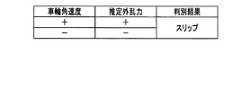
続いて、図5〜図8を参照して、各推定外乱力の種別の判別条件を説明する。ここでは、右車輪4Rについて説明するが、左車輪4Lについても同様の判別条件が用いられる。《スリップ:図4のステップS205》
図5は、スリップに対する判別条件を示す表である。
なお、図5〜図8において、車輪角速度が「+」であるとは、倒立振子型移動装置1が前方に向うよう車輪4Rが回転していることを示し、「−」であるとは、倒立振子型移動装置1が後方に向うよう車輪4Rが回転していることを示す。
また、推定外乱力が「+」であるとは、倒立振子型移動装置1が前方に向うように、車輪4Rに対して推定外乱力が余計に働いていることを示し、「−」であるとは、倒立振子型移動装置1が後方に向うように、車輪4Rに対して推定外乱力が余計に働いていることを示す。
なお、推定外乱力が「0」であるとは、余分な推定外乱力が働いていない状態を示す、[Determination condition]
Subsequently, with reference to FIG. 5 to FIG. 8, a determination condition for each type of estimated disturbance force will be described. Here, the
FIG. 5 is a table showing discrimination conditions for slipping.
5 to 8, the wheel angular velocity of “+” indicates that the
Further, the estimated disturbance force being “+” indicates that the estimated disturbance force is excessively applied to the
Note that an estimated disturbance force of “0” indicates a state in which an extra estimated disturbance force is not working.
図5に示すように、最初、車輪角速度、推定外乱力がともに「+」であった後、所定時間内に、両者とも「−」に変化した場合、倒立制御部24は外乱原因の判別結果として「スリップ」を出力する。つまり、スリップを起こしたため、前方に進んでいた倒立振子型移動装置1の車輪4Rが、車輪角速度および推定外乱力ともに「+」方向に余計な力が働いた後、バランスをとるため、倒立振子型移動装置1が逆方向に進もうとすると、ここでもスリップが生じて、車輪角速度および推定外乱力ともに「−」方向に余計な力が働いた場合、倒立制御部24は外乱原因を「スリップ」と判別する。
なお、判別条件が生じる順番は逆でもよい。つまり、最初、車輪角速度および推定外乱力の両者が「−」であり、所定時間内に、車輪角速度および推定外乱力の両者が「+」となった場合でも、倒立制御部24は外乱原因を「スリップ」と判別する。As shown in FIG. 5, when both the wheel angular velocity and the estimated disturbance force are initially “+” and both change to “−” within a predetermined time, the
Note that the order in which the determination conditions occur may be reversed. That is, at first, both the wheel angular velocity and the estimated disturbance force are “−”, and even when both the wheel angular velocity and the estimated disturbance force are “+” within a predetermined time, the
《段差:図4のステップS207》
(前方上り段差)
図6は、段差に対する判別条件を示す表である。
図6に示すように、現在(あるいは所定の時点)の車輪角速度が「+」で、推定外乱力が「−」である状態から、所定時間内に車輪角速度が「−」、推定外乱力が「0」の状態となった場合、倒立制御部24は外乱原因を「前方上り段差」と判別する。これは、倒立振子型移動装置1が段差にぶつかって、その段差を乗り越えている状態(車輪角速度「+」、推定外乱力「−」)から、段差を乗り越えた後、バランスをとるため、倒立振子型移動装置1がやや後退した(車輪角速度「−」、推定外乱力「0」)ことを意味している。<< Step: Step S207 in FIG. 4 >>
(Front up step)
FIG. 6 is a table showing discrimination conditions for steps.
As shown in FIG. 6, from a state where the current (or predetermined time) wheel angular velocity is “+” and the estimated disturbance force is “−”, the wheel angular velocity is “−” and the estimated disturbance force is within a predetermined time. When the state becomes “0”, the
なお、判別条件が生じる順番は逆でもよい。つまり、最初、車輪角速度が「−」で推定外乱力が「0」の状態から、所定時間内に、車輪角速度が「+」になり、推定外乱力が「−」となった場合でも、倒立制御部24は外乱原因を「前方上り段差」と判別する。これは、倒立振子型移動装置1が段差にぶつかった後、一旦後退してから、段差を乗り越えることを意味する。 Note that the order in which the determination conditions occur may be reversed. That is, at first, even if the wheel angular velocity becomes “+” and the estimated disturbance force becomes “−” within a predetermined time from the state where the wheel angular velocity is “−” and the estimated disturbance force is “0”, it is inverted. The
(前方下り段差)
また、現在(あるいは所定の時点)の車輪角速度および推定外乱力の両者が「+」である状態から、所定時間内に車輪角速度が「−」、推定外乱力が「0」の状態となった場合、倒立制御部24は外乱原因を「前方下り段差」と判別する。これは、前進している下り段差を降りている状態(車輪角速度「+」、推定外乱力「+」)の後、倒立振子型移動装置1が、やや後退した(車輪角速度「−」、推定外乱力「0」)ことを意味している。(Front descending step)
Also, from the state where both the wheel angular velocity and the estimated disturbance force at the current (or a predetermined time) are “+”, the wheel angular velocity is “−” and the estimated disturbance force is “0” within a predetermined time. In this case, the
なお、判別条件が生じる順番は逆でもよい。つまり、最初、車輪角速度が「−」で推定外乱力が「0」の状態から、所定時間内に、車輪角速度および推定外乱力の両者が「+」となった場合でも、倒立制御部24は外乱原因を「前方下り段差」と判別する。これは、倒立振子型移動装置1が段差に遭遇した時点で、一旦後退してから、段差を降りることを意味する。 Note that the order in which the determination conditions occur may be reversed. That is, even when the wheel angular velocity and the estimated disturbance force both become “+” within a predetermined time from the state where the wheel angular velocity is “−” and the estimated disturbance force is “0”, the
(後方上り段差)
さらに、現在(あるいは所定の時点)の車輪角速度が「−」で、推定外乱力が「+」である状態から、所定時間内に車輪角速度が「+」、推定外乱力が「0」の状態となった場合、倒立制御部24は外乱原因を「後方上り段差」と判別する。これは、後進している倒立振子型移動装置1が段差にぶつかって、その段差を後ろ向きに乗り越えている状態(車輪角速度「−」、推定外乱力「+」)から、段差を乗り越えた後、バランスをとるため、倒立振子型移動装置1がやや前進した(車輪角速度「+」、推定外乱力「0」)ことを意味している。(Back up step)
Furthermore, from the state where the current (or predetermined time) wheel angular velocity is “−” and the estimated disturbance force is “+”, the wheel angular velocity is “+” and the estimated disturbance force is “0” within a predetermined time. In this case, the
なお、判別条件が生じる順番は逆でもよい。つまり、最初、車輪角速度が「+」で推定外乱力が「0」の状態から、所定時間内に、車輪角速度が「−」になり、推定外乱力が「+」となった場合でも、倒立制御部24は外乱原因を「後方上り段差」と判別する。これは、倒立振子型移動装置1が後ろ向きに段差にぶつかった後、一旦前進してから、段差を乗り越えることを意味する。 Note that the order in which the determination conditions occur may be reversed. That is, at first, even when the wheel angular velocity becomes “−” and the estimated disturbance force becomes “+” within a predetermined time from the state where the wheel angular velocity is “+” and the estimated disturbance force is “0”, the vehicle is inverted. The
(後方下り段差)
さらに、現在(あるいは所定の時点)の車輪角速度および推定外乱力の両者が「−」である状態から、所定時間内に車輪角速度が「+」、推定外乱力が「0」の状態となった場合、倒立制御部24は外乱原因を「後方下り段差」と判別する。これは、後進している倒立振子型移動装置1が段差を降りている状態(車輪角速度「−」、推定外乱力「−」)の状態後、バランスをとるため、倒立振子型移動装置1がやや前進した(車輪角速度「+」、推定外乱力「0」)ことを意味している。(Backward descending step)
Furthermore, from the state where both the wheel angular velocity and the estimated disturbance force at the present time (or at a predetermined time) are “−”, the wheel angular velocity is “+” and the estimated disturbance force is “0” within a predetermined time. In this case, the
なお、判別条件が生じる順番は逆でもよい。つまり、最初、車輪角速度が「+」で推定外乱力が「0」の状態から、所定時間内に、車輪角速度が「−」になり、推定外乱力が「−」となった場合でも、倒立制御部24は外乱原因を「後方下り段差」と判別する。これは、倒立振子型移動装置1が後ろ向きに段差に遭遇した後、一旦前進してから、段差を降りることを意味する。 Note that the order in which the determination conditions occur may be reversed. That is, at first, even when the wheel angular velocity becomes “−” and the estimated disturbance force becomes “−” within a predetermined time from the state where the wheel angular velocity is “+” and the estimated disturbance force is “0”, the vehicle is inverted. The
《斜面:図4のステップS210》
(上り傾斜面)
図7は、斜面に対する判別条件を示す表である。
図7に示すように、現在(あるいは所定の時点)の車輪角速度が「+」で、推定外乱力が「−」である状態から、所定時間内に車輪角速度および推定外乱力の両者が「−」の状態となった場合、倒立制御部24は外乱原因を「上り傾斜面」と判別する。これは、倒立振子型移動装置1が、上り傾斜面を上った(車輪角速度「+」、推定外乱力「−」)後、バランスをとるため、一旦、この斜面を下る(車輪角速度「−」、推定外乱力「−」)ことを意味している。<< Slope: Step S210 in FIG. 4 >>
(Up slope)
FIG. 7 is a table showing discrimination conditions for slopes.
As shown in FIG. 7, from the state where the current (or predetermined time) wheel angular velocity is “+” and the estimated disturbance force is “−”, both the wheel angular velocity and the estimated disturbance force are “−” within a predetermined time. In the state of “”, the
なお、判別条件が生じる順番は逆でもよい。つまり、最初、車輪角速度および推定外乱力の両者が「−」の状態から、所定時間内に、車輪角速度が「+」になり、推定外乱力が「−」となった場合でも、倒立制御部24は外乱原因を「上り傾斜面」と判別する。これは、倒立振子型移動装置1が上り傾斜面を上り始めた直後に、バランスをとるため、一旦傾斜面を少し下ってから、傾斜面を登ることを意味する。 Note that the order in which the determination conditions occur may be reversed. That is, at first, even if the wheel angular velocity becomes “+” and the estimated disturbance force becomes “−” within a predetermined time from the state where both the wheel angular velocity and the estimated disturbance force are “−”, the
(下り傾斜面)
また、現在(あるいは所定の時点)の車輪角速度および推定外乱力の両者が「+」である状態から、所定時間内に車輪角速度が「−」、推定外乱力が「+」の状態となった場合、倒立制御部24は推定外乱力の原因を「下り傾斜面」と判別する。これは、前進している倒立振子型移動装置1が、下り傾斜面を下った(車輪角速度「+」、推定外乱力「+」)後、バランスをとるため、倒立振子型移動装置1が、一旦、この斜面を登る(車輪角速度「−」、推定外乱力「+」)ことを意味している。(Down slope)
In addition, from the state where both the wheel angular velocity and the estimated disturbance force at the current (or predetermined time) are “+ ”, the wheel angular velocity is “−” and the estimated disturbance force is “+” within a predetermined time. In this case, the
なお、判別条件が生じる順番は逆でもよい。つまり、最初、車輪角速度が「−」で推定外乱力が「+」の状態から、所定時間内に、車輪角速度および推定外乱力の両者が「+」となった場合でも、倒立制御部24は外乱原因を「下り傾斜面」と判別する。これは、倒立振子型移動装置1が下り傾斜面を下り始めた直後に、バランスをとるため、一旦傾斜面を登ってから、傾斜面を下ることを意味する。 Note that the order in which the determination conditions occur may be reversed. That is, even when the wheel angular velocity and the estimated disturbance force both become “+” within a predetermined time from the state where the wheel angular velocity is “−” and the estimated disturbance force is “+”, the
《柔らかい路面:図4のステップS212》
図8は、柔らかい路面に対する判別条件を示す表である。
図8に示すように、路面が柔らかいとき、車輪4Rが路面に沈み込むので、倒立振子型移動装置1が前後に動いても、車輪4Rには抵抗力(つまり、車輪角速度とは逆方向の推定外乱力)が働く。従って、図8に示すように、前進しようとしているが、後ろ向きに抵抗(推定外乱力)が働いている状態(車輪角速度「+」、推定外乱力「−」)から、所定時間内に後進しようとしているが、前向きに抵抗(推定外乱力)が働いている状態(車輪角速度「−」、推定外乱力「+」)となったとき、倒立制御部24は外乱原因を「柔らかい路面」と判別する。<< Soft road surface: Step S212 in FIG. 4 >>
FIG. 8 is a table showing discrimination conditions for soft road surfaces.
As shown in FIG. 8, when the road surface is soft, the
この判別条件が生じる順番は逆でもよい。つまり、倒立振子型移動装置1が後進しようとしているが、前向きに抵抗(推定外乱力)が働いている状態(車輪角速度「−」、推定外乱力「+」)状態から、所定時間内に、前進しようとしているが、後ろ向きに抵抗(推定外乱力)が働いている状態(車輪角速度「+」、推定外乱力「−」)となったとき、倒立制御部24は外乱原因を「柔らかい路面」と判別する。 The order in which the determination conditions occur may be reversed. That is, the inverted pendulum type moving device 1 is going to move backward, but within a predetermined time from a state where the resistance (estimated disturbance force) works forward (wheel angular velocity “−”, estimated disturbance force “+”), When the vehicle is going to move forward but resistance (estimated disturbance force) is working backward (wheel angular velocity “+”, estimated disturbance force “−”), the
(別の実施形態)
なお、本実施形態では、行動決定部21において移動目標や、経路が予めプログラムされているとしたが、人間がジョイスティックやコンソールなどを用いて、直接指定(操縦)してもよい。また、人間がリアルタイムに操縦を行う場合においては、行動決定部21が生成する移動目標の中に移動先位置が含まれない。従って、経路計画部22が不要となり、速度計画部23は並進に関わる速度計画のみを計画し、旋回に関する計画は、常に操縦者によりリアルタイムで入力される旋回角速度を用いる。この場合、倒立制御部24は、式(5)、式(6)によるτs,τcの算出に関し、位置と旋回角度に関する項を「0」として扱うとよい。(Another embodiment)
In this embodiment, it is assumed that the movement target and the route are programmed in advance in the
また、図3における一連の処理において、倒立制御部24は推定外乱力DR,DLをそのまま用いているが、推定外乱力DR,DLの値をローパスフィルタなどのデジタルフィルタを介して整形して用いてもよい。また車輪4R,4L自体の柔らかさに由来する特性を取り除くため、倒立制御部24が事前に十分硬い路面上で車輪角速度dφR,dφLの正負それぞれの場合において、推定外乱力DR,DLが、どの様な値をとるかを測定し、その測定結果を図3の処理で得られた推定外乱力DR,DLから、車輪角速度dφR,dφLの正負それぞれの場合においてそれぞれ予め減じておいてもよい。Further, in the series of processes in FIG. 3, the
そして、倒立制御部24は、図4の外乱原因の判別において閾値を用い、外乱力(推定外乱力)の絶対値が閾値より小さい場合は「0」として扱うようにしてもよい。 Then, the
さらに、倒立制御部24は、車輪角速度および車輪角度を、それぞれ倒立振子型移動装置1の移動速度と位置、旋回角速度で変換したものを代わりに用いてもよい。 Further, the
さらに、倒立制御部24は、段差、路面傾斜、柔らかい路面などの外乱力の種別を判別した際に、路面形状と位置情報を同時に記憶部(不図示)に記録し、次回以降の路面形状と位置情報の記憶部への追加時に、記録してある路面形状や、位置情報を用いて補正を行うなどの利用をしてもよい。 Further, the
また、本実施形態では外乱力を外乱推定オブザーバによる推定外乱力としたが、これに限らず、センサによる実測の外乱力を使用してもよい。 In the present embodiment, the disturbance force is the estimated disturbance force by the disturbance estimation observer. However, the present invention is not limited to this, and a disturbance force actually measured by a sensor may be used.
本実施形態によれば、前記したように外乱力(推定外乱力)の種類を判別し、その判別結果に応じた指示トルクを決定するので、様々な種類の外乱力に対応でき、安定した走行を可能とする倒立振子型移動装置1を提供することができる。 According to the present embodiment, as described above, the type of disturbance force (estimated disturbance force) is determined, and the command torque according to the determination result is determined. Thus, the inverted pendulum type moving device 1 can be provided.
1 倒立振子型移動装置
2 計算部
3 移動機構部
4,4L,4R 車輪
5 姿勢センサ
21 行動決定部
22 経路計画部
23 速度計画部
24 倒立制御部
31,31L,31R モータ
32 機構制御部DESCRIPTION OF SYMBOLS 1 Inverted pendulum
Claims (12)
Translated fromJapanese前記車輪の回転状態を基に、外乱力の原因を判別し、前記判別結果に基づいて、前記車輪への出力トルクを決定する倒立制御部を
有し、
前記車輪の回転状態は、車輪角速度と、前記車輪に加えられる外乱力であり、
前記倒立制御部は、
以下の式(1)が成立している場合、前記外乱力の原因を空転と判別する
ことを特徴とする倒立振子型移動装置。
Based on the rotational state of the wheel, to determine the cause of the disturbance force, on the basis of the determination result,it has a inversion control unit for determining an output torque to thewheel,
The rotational state of the wheel is a wheel angular velocity and a disturbance force applied to the wheel,
The inverted controller is
An inverted pendulum type moving device characterizedin thatwhen the following formula (1) holds, the cause of the disturbance force is determined to beidling .
前記車輪の回転状態を基に、外乱力の原因を判別し、前記判別結果に基づいて、前記車輪への出力トルクを決定する倒立制御部を
有し、
前記車輪の回転状態は、車輪角速度と、前記車輪に加えられる外乱力であり、
前記倒立制御部は、
前記車輪角速度および前記外乱力の方向が同じである状態から、所定時間内において、ともに逆方向となった場合、前記外乱力の原因をスリップと判別する
ことを特徴とする倒立振子型移動装置。A plurality ofwheels are arranged onone wheel orcoaxial, and the center of gravity of the portion to be placed on the wheel is an inverted pendulum type moving device located in the upper Riby carshaft,
Based on the rotational state of the wheel, to determine the cause of the disturbance force, on the basis of the determination result,it has a inversion control unit for determining an output torque to thewheel,
The rotational state of the wheel is a wheel angular velocity and a disturbance force applied to the wheel,
The inverted controller is
An inverted pendulum type moving device characterizedin thatwhen the wheel angular velocity and the direction of the disturbance force are the same within a predetermined period of time from the same state, the cause of the disturbance force is determined to be aslip .
前記車輪の回転状態を基に、外乱力の原因を判別し、前記判別結果に基づいて、前記車輪への出力トルクを決定する倒立制御部を
有し、
前記車輪の回転状態は、車輪角速度と、前記車輪に加えられる外乱力であり、
前記倒立制御部は、
所定時間内において、前記車輪角速度の方向が逆方向に変化し、かつ、前記外乱力が存在する状態から、0へと変化した場合、
または、
所定時間内において、前記車輪角速度の方向が逆方向に変化し、かつ、前記外乱力が0から、前記外乱力が存在する状態に変化した場合、
前記外乱力の原因を段差と判別する
ことを特徴とする倒立振子型移動装置。A plurality ofwheels are arranged onone wheel orcoaxial, and the center of gravity of the portion to be placed on the wheel is an inverted pendulum type moving device located in the upper Riby carshaft,
Based on the rotational state of the wheel, to determine the cause of the disturbance force, on the basis of the determination result,it has a inversion control unit for determining an output torque to thewheel,
The rotational state of the wheel is a wheel angular velocity and a disturbance force applied to the wheel,
The inverted controller is
Within a predetermined time, when the direction of the wheel angular velocity changes in the reverse direction and the state where the disturbance force exists changes to 0,
Or
Within a predetermined time, when the direction of the wheel angular velocity is changed in the reverse direction and the disturbance force is changed from 0 to a state where the disturbance force exists,
An inverted pendulum type moving device characterizedin thatthe cause of the disturbance force is determined as a step .
前記車輪の回転状態を基に、外乱力の原因を判別し、前記判別結果に基づいて、前記車輪への出力トルクを決定する倒立制御部を
有し、
前記車輪の回転状態は、車輪角速度と、前記車輪に加えられる外乱力であり、
前記倒立制御部は、
所定時間内において、前記車輪角速度の方向が前方へ移動する回転から、後方へ移動する回転に変化し、かつ、前記外乱力が前記車輪の回転方向に対して逆方向から、0へと変化した場合、
または、
所定時間内において、前記車輪角速度の方向が後方へ移動する回転から、前方へ移動する回転に変化し、かつ、前記外乱力が0から、前記車輪の回転方向に対して逆方向へと変化した場合、
前記外乱力の原因を前方上り段差と判別する
ことを特徴とする倒立振子型移動装置。A plurality ofwheels are arranged onone wheel orcoaxial, and the center of gravity of the portion to be placed on the wheel is an inverted pendulum type moving device located in the upper Riby carshaft,
Based on the rotational state of the wheel, to determine the cause of the disturbance force, on the basis of the determination result,it has a inversion control unit for determining an output torque to thewheel,
The rotational state of the wheel is a wheel angular velocity and a disturbance force applied to the wheel,
The inverted controller is
Within a predetermined time, the direction of the wheel angular velocity has changed from a rotation that moves forward to a rotation that moves backward, and the disturbance force has changed from a direction opposite to the rotation direction of the wheel to 0. If
Or
Within a predetermined time, the direction of the wheel angular velocity changed from a rotation moving backward to a rotation moving forward, and the disturbance force changed from 0 to the opposite direction to the rotation direction of the wheel. If
An inverted pendulum type moving device characterizedin thatthe cause of the disturbance force is determined as a forward ascending step .
前記車輪の回転状態を基に、外乱力の原因を判別し、前記判別結果に基づいて、前記車輪への出力トルクを決定する倒立制御部を
有し、
前記車輪の回転状態は、車輪角速度と、前記車輪に加えられる外乱力であり、
前記倒立制御部は、
所定時間内において、前記車輪角速度の方向が前方へ移動する回転から、後方へ移動する回転に変化し、かつ、前記外乱力が前記車輪の回転方向に対して順方向から、0へと変化した場合、
または、
所定時間内において、前記車輪角速度の方向が後方へ移動する回転から、前方へ移動する回転に変化し、かつ、前記外乱力が0から、前記車輪の回転方向に対して順方向へと変化した場合、
前記外乱力の原因を前方下り段差と判別する
ことを特徴とする倒立振子型移動装置。A plurality ofwheels are arranged onone wheel orcoaxial, and the center of gravity of the portion to be placed on the wheel is an inverted pendulum type moving device located in the upper Riby carshaft,
Based on the rotational state of the wheel, to determine the cause of the disturbance force, on the basis of the determination result,it has a inversion control unit for determining an output torque to thewheel,
The rotational state of the wheel is a wheel angular velocity and a disturbance force applied to the wheel,
The inverted controller is
Within a predetermined time, the direction of the wheel angular velocity changed from a rotation moving forward to a rotation moving backward, and the disturbance force changed from a forward direction to 0 with respect to the rotation direction of the wheel. If
Or
Within a predetermined time, the direction of the wheel angular velocity changes from a rotation that moves backward to a rotation that moves forward, and the disturbance force changes from 0 to the forward direction with respect to the rotation direction of the wheel. If
An inverted pendulum type moving device characterizedin thatthe cause of the disturbance force is determined as a forward descending step .
前記車輪の回転状態を基に、外乱力の原因を判別し、前記判別結果に基づいて、前記車輪への出力トルクを決定する倒立制御部を
有し、
前記車輪の回転状態は、車輪角速度と、前記車輪に加えられる外乱力であり、
前記倒立制御部は、
所定時間内において、前記車輪角速度の方向が後方へ移動する回転から、前方へ移動する回転に変化し、かつ、前記外乱力が前記車輪の回転方向に対して順方向から、0へと変化した場合、
または、
所定時間内において、前記車輪角速度の方向が前方へ移動する回転から、後方へ移動する回転に変化し、かつ、前記外乱力が0から、前記車輪の回転方向に対して順方向へと変化した場合、
前記外乱力の原因を後方上り段差と判別する
ことを特徴とする倒立振子型移動装置。A plurality ofwheels are arranged onone wheel orcoaxial, and the center of gravity of the portion to be placed on the wheel is an inverted pendulum type moving device located in the upper Riby carshaft,
Based on the rotational state of the wheel, to determine the cause of the disturbance force, on the basis of the determination result,it has a inversion control unit for determining an output torque to thewheel,
The rotational state of the wheel is a wheel angular velocity and a disturbance force applied to the wheel,
The inverted controller is
Within a predetermined time, the direction of the wheel angular velocity changed from a rotation moving backward to a rotation moving forward, and the disturbance force changed from a forward direction to 0 with respect to the rotation direction of the wheel. If
Or
Within a predetermined time, the direction of the wheel angular velocity changed from a rotation moving forward to a rotation moving backward, and the disturbance force changed from 0 to the forward direction with respect to the rotation direction of the wheel. If
An inverted pendulum type moving device characterizedin thatthe cause of the disturbance force is determined as a rear upward step .
前記車輪の回転状態を基に、外乱力の原因を判別し、前記判別結果に基づいて、前記車輪への出力トルクを決定する倒立制御部を
有し、
前記車輪の回転状態は、車輪角速度と、前記車輪に加えられる外乱力であり、
前記倒立制御部は、
所定時間内において、前記車輪角速度の方向が後方へ移動する回転から、前方へ移動する回転に変化し、かつ、前記外乱力が前記車輪の回転方向に対して逆方向から、0へと変化した場合、
または、
所定時間内において、前記車輪角速度の方向が前方へ移動する回転から、後方へ移動する回転に変化し、かつ、前記外乱力が0から、前記車輪の回転方向に対して逆方向へと変化した場合、
前記外乱力の原因を後方下り段差と判別する
ことを特徴とする倒立振子型移動装置。A plurality ofwheels are arranged onone wheel orcoaxial, and the center of gravity of the portion to be placed on the wheel is an inverted pendulum type moving device located in the upper Riby carshaft,
Based on the rotational state of the wheel, to determine the cause of the disturbance force, on the basis of the determination result,it has a inversion control unit for determining an output torque to thewheel,
The rotational state of the wheel is a wheel angular velocity and a disturbance force applied to the wheel,
The inverted controller is
Within a predetermined time, the direction of the wheel angular velocity has changed from a rotation that moves backward to a rotation that moves forward, and the disturbance force has changed from a direction opposite to the rotation direction of the wheel to 0. If
Or
Within a predetermined time, the direction of the wheel angular velocity has changed from a rotation that moves forward to a rotation that moves backward, and the disturbance force has changed from 0 to a direction opposite to the rotation direction of the wheel. If
An inverted pendulum type moving device characterizedin thatthe cause of the disturbance force is determined as a backward descending step .
前記車輪の回転状態を基に、外乱力の原因を判別し、前記判別結果に基づいて、前記車輪への出力トルクを決定する倒立制御部を
有し、
前記車輪の回転状態は、車輪角速度と、前記車輪に加えられる外乱力であり、
前記倒立制御部は、
所定時間内に、前記外乱力の方向に変化はないが、前記車輪角速度の方向が逆方向に変化した場合、前記外乱力の原因を傾斜面と判別する
ことを特徴とする倒立振子型移動装置。A plurality ofwheels are arranged onone wheel orcoaxial, and the center of gravity of the portion to be placed on the wheel is an inverted pendulum type moving device located in the upper Riby carshaft,
Based on the rotational state of the wheel, to determine the cause of the disturbance force, on the basis of the determination result,it has a inversion control unit for determining an output torque to thewheel,
The rotational state of the wheel is a wheel angular velocity and a disturbance force applied to the wheel,
The inverted controller is
Inverted pendulum type moving apparatus characterizedin that when the direction of the wheel angular velocity does not change within a predetermined time, but the direction of the wheel angular velocity changes in the opposite direction, the cause of the disturbance force is determined as an inclined surface. .
前記車輪の回転状態を基に、外乱力の原因を判別し、前記判別結果に基づいて、前記車輪への出力トルクを決定する倒立制御部を
有し、
前記車輪の回転状態は、車輪角速度と、前記車輪に加えられる外乱力であり、
前記倒立制御部は、
所定時間内において、前記外乱力の方向が、前記車輪の回転に対して逆方向のままで、前記車輪角速度の方向が逆方向に変化した場合、前記外乱力の原因を上り傾斜面と判別する
ことを特徴とする倒立振子型移動装置。A plurality ofwheels are arranged onone wheel orcoaxial, and the center of gravity of the portion to be placed on the wheel is an inverted pendulum type moving device located in the upper Riby carshaft,
Based on the rotational state of the wheel, to determine the cause of the disturbance force, on the basis of the determination result,it has a inversion control unit for determining an output torque to thewheel,
The rotational state of the wheel is a wheel angular velocity and a disturbance force applied to the wheel,
The inverted controller is
If the direction of the disturbance force remains in the reverse direction with respect to the rotation of the wheel within a predetermined time, and the direction of the wheel angular velocity is changed in the reverse direction, the cause of the disturbance force is determined as an upward inclined surface. An inverted pendulum type moving device characterized by that.
前記車輪の回転状態を基に、外乱力の原因を判別し、前記判別結果に基づいて、前記車輪への出力トルクを決定する倒立制御部を
有し、
前記車輪の回転状態は、車輪角速度と、前記車輪に加えられる外乱力であり、
前記倒立制御部は、
所定時間内において、前記外乱力の方向が、前記車輪の回転に対して順方向のままで、前記車輪角速度の方向が逆方向に変化した場合、前記外乱力の原因を下り傾斜面と判別する
ことを特徴とする倒立振子型移動装置。A plurality ofwheels are arranged onone wheel orcoaxial, and the center of gravity of the portion to be placed on the wheel is an inverted pendulum type moving device located in the upper Riby carshaft,
Based on the rotational state of the wheel, to determine the cause of the disturbance force, on the basis of the determination result,it has a inversion control unit for determining an output torque to thewheel,
The rotational state of the wheel is a wheel angular velocity and a disturbance force applied to the wheel,
The inverted controller is
If the direction of the disturbance force remains in the forward direction with respect to the rotation of the wheel and the direction of the wheel angular velocity changes in the reverse direction within a predetermined time, the cause of the disturbance force is determined to be a downward inclined surface. An inverted pendulum type moving device characterized by that.
前記車輪の回転状態を基に、外乱力の原因を判別し、前記判別結果に基づいて、前記車輪への出力トルクを決定する倒立制御部を
有し、
前記車輪の回転状態は、車輪角速度と、前記車輪に加えられる外乱力であり、
前記倒立制御部は、
前記車輪角速度および前記外乱力の方向が互いに逆方向の状態であり、所定時間内において前記車輪角速度および前記外乱力のそれぞれの方向が逆方向に変化した場合、前記外乱力の原因を柔らかい路面と判別する
ことを特徴とする倒立振子型移動装置。A plurality ofwheels are arranged onone wheel orcoaxial, and the center of gravity of the portion to be placed on the wheel is an inverted pendulum type moving device located in the upper Riby carshaft,
Based on the rotational state of the wheel, to determine the cause of the disturbance force, on the basis of the determination result,it has a inversion control unit for determining an output torque to thewheel,
The rotational state of the wheel is a wheel angular velocity and a disturbance force applied to the wheel,
The inverted controller is
When the wheel angular velocity and the direction of the disturbance force are in opposite directions, and the respective directions of the wheel angular velocity and the disturbance force change in the reverse direction within a predetermined time, the cause of the disturbance force is a soft road surface. An inverted pendulum type moving device characterizedby discriminating .
前記車輪角速度の方向が、所定時間内に変化している場合、車輪の回転方向の急激な変化が生じていると判別する
ことを特徴とする請求項1から請求項11のいずれか一項に記載の倒立振子型移動装置。The inverted controller is
12. The method according toclaim 1, wherein when the direction of the wheel angular velocity has changed within a predetermined time, it is determined that a sudden change in the rotation direction of the wheel has occurred. The inverted pendulum type moving device described.
Applications Claiming Priority (1)
| Application Number | Priority Date | Filing Date | Title |
|---|---|---|---|
| PCT/JP2011/078576WO2013084354A1 (en) | 2011-12-09 | 2011-12-09 | Inverted pendulum type mobile device and control method therefor |
Publications (2)
| Publication Number | Publication Date |
|---|---|
| JPWO2013084354A1 JPWO2013084354A1 (en) | 2015-04-27 |
| JP5873879B2true JP5873879B2 (en) | 2016-03-01 |
Family
ID=48573752
Family Applications (1)
| Application Number | Title | Priority Date | Filing Date |
|---|---|---|---|
| JP2013548037AActiveJP5873879B2 (en) | 2011-12-09 | 2011-12-09 | Inverted pendulum type moving device |
Country Status (3)
| Country | Link |
|---|---|
| US (1) | US9290109B2 (en) |
| JP (1) | JP5873879B2 (en) |
| WO (1) | WO2013084354A1 (en) |
Families Citing this family (7)
| Publication number | Priority date | Publication date | Assignee | Title |
|---|---|---|---|---|
| CN105270525B (en)* | 2015-09-28 | 2018-02-02 | 小米科技有限责任公司 | The control method and device of two-wheeled balance car |
| CN106904233B (en)* | 2017-05-04 | 2019-04-09 | 歌尔科技有限公司 | A kind of two-wheel robot lifts detection method and device |
| US11409289B2 (en)* | 2018-02-26 | 2022-08-09 | Sony Corporation | Information processing device, information processing method, and program |
| JP2022078372A (en)* | 2019-03-27 | 2022-05-25 | パナソニックIpマネジメント株式会社 | Mobile work robot control device |
| CN114764241B (en) | 2021-01-14 | 2025-02-18 | 腾讯科技(深圳)有限公司 | Motion state control method, device, equipment and readable storage medium |
| KR20230172332A (en)* | 2022-06-15 | 2023-12-22 | 현대자동차주식회사 | Apparatus for controlling robot and method thereof |
| JP2024157847A (en)* | 2023-04-26 | 2024-11-08 | 双葉電子工業株式会社 | Gyro unit, control system |
Family Cites Families (7)
| Publication number | Priority date | Publication date | Assignee | Title |
|---|---|---|---|---|
| JP5107533B2 (en)* | 2006-06-01 | 2012-12-26 | 株式会社日立製作所 | Mobile robot |
| JP5024652B2 (en)* | 2006-09-15 | 2012-09-12 | 株式会社エクォス・リサーチ | vehicle |
| JP4779982B2 (en)* | 2007-02-02 | 2011-09-28 | トヨタ自動車株式会社 | MOBILE BODY AND METHOD FOR CONTROLLING MOBILE BODY |
| JP2008263676A (en) | 2007-04-10 | 2008-10-30 | Toyota Central R&D Labs Inc | Self-propelled vehicle and its control device and control method |
| JP5223265B2 (en)* | 2007-08-10 | 2013-06-26 | 株式会社エクォス・リサーチ | vehicle |
| CN101784437B (en) | 2007-08-10 | 2012-04-18 | 爱考斯研究株式会社 | vehicle |
| JP5330200B2 (en)* | 2009-11-13 | 2013-10-30 | 本田技研工業株式会社 | Control device for inverted pendulum type vehicle |
- 2011
- 2011-12-09WOPCT/JP2011/078576patent/WO2013084354A1/enactiveApplication Filing
- 2011-12-09USUS14/363,747patent/US9290109B2/enactiveActive
- 2011-12-09JPJP2013548037Apatent/JP5873879B2/enactiveActive
Also Published As
| Publication number | Publication date |
|---|---|
| US20150274032A1 (en) | 2015-10-01 |
| JPWO2013084354A1 (en) | 2015-04-27 |
| US9290109B2 (en) | 2016-03-22 |
| WO2013084354A1 (en) | 2013-06-13 |
Similar Documents
| Publication | Publication Date | Title |
|---|---|---|
| JP5873879B2 (en) | Inverted pendulum type moving device | |
| KR100685339B1 (en) | Mobile robot | |
| JP4434186B2 (en) | MOBILE BODY AND METHOD FOR CONTROLLING MOBILE BODY | |
| JP4760162B2 (en) | Control method of mobile cart and mobile cart | |
| EP2083340B1 (en) | Inverted type movable body and control method thereof | |
| US20090105908A1 (en) | Apparatus and Method for Controlling Vehicle Motion | |
| JP5919889B2 (en) | Vehicle attitude control device | |
| JP4138546B2 (en) | Mobile cart and control method of mobile cart | |
| JPWO2017175844A1 (en) | Attitude estimation device and transportation equipment | |
| WO2013001658A1 (en) | Inverted pendulum type moving body equipped with velocity planning device | |
| US20200130701A1 (en) | Pseudo-emotion generation method, travel evaluation method, and travel evaluation system | |
| JP2010247804A (en) | Attitude control device | |
| CN108725666B (en) | Inverted pendulum | |
| JP2012126293A (en) | Steering controlling system of vehicle | |
| JP5617595B2 (en) | Inverted moving body and control method thereof | |
| Ojeda et al. | The FLEXnav precision dead-reckoning system | |
| JP5369602B2 (en) | vehicle | |
| JP5772373B2 (en) | Inverted moving body control device and control method thereof | |
| JP6380951B2 (en) | Navigation body control device, navigation body, navigation body control method, program | |
| JP5786633B2 (en) | MOBILE BODY CONTROL DEVICE, ITS CONTROL METHOD, AND PROGRAM | |
| JP5962068B2 (en) | Vehicle attitude control device | |
| JP7238490B2 (en) | Sensor error correction device and sensor error correction program | |
| JP5200574B2 (en) | vehicle | |
| JP5874618B2 (en) | Mobile device | |
| CN119984258A (en) | A method for enhancing inertial positioning of ground vehicles considering motion constraints |
Legal Events
| Date | Code | Title | Description |
|---|---|---|---|
| A131 | Notification of reasons for refusal | Free format text:JAPANESE INTERMEDIATE CODE: A131 Effective date:20150630 | |
| A521 | Request for written amendment filed | Free format text:JAPANESE INTERMEDIATE CODE: A523 Effective date:20150828 | |
| TRDD | Decision of grant or rejection written | ||
| A01 | Written decision to grant a patent or to grant a registration (utility model) | Free format text:JAPANESE INTERMEDIATE CODE: A01 Effective date:20151222 | |
| A61 | First payment of annual fees (during grant procedure) | Free format text:JAPANESE INTERMEDIATE CODE: A61 Effective date:20160118 | |
| R150 | Certificate of patent or registration of utility model | Ref document number:5873879 Country of ref document:JP Free format text:JAPANESE INTERMEDIATE CODE: R150 |