JP5870973B2 - Linear motor - Google Patents
Linear motorDownload PDFInfo
- Publication number
- JP5870973B2 JP5870973B2JP2013156803AJP2013156803AJP5870973B2JP 5870973 B2JP5870973 B2JP 5870973B2JP 2013156803 AJP2013156803 AJP 2013156803AJP 2013156803 AJP2013156803 AJP 2013156803AJP 5870973 B2JP5870973 B2JP 5870973B2
- Authority
- JP
- Japan
- Prior art keywords
- magnetic field
- armature
- stator
- field sensor
- linear motor
- Prior art date
- Legal status (The legal status is an assumption and is not a legal conclusion. Google has not performed a legal analysis and makes no representation as to the accuracy of the status listed.)
- Active
Links
Images


Classifications
- H—ELECTRICITY
- H02—GENERATION; CONVERSION OR DISTRIBUTION OF ELECTRIC POWER
- H02K—DYNAMO-ELECTRIC MACHINES
- H02K41/00—Propulsion systems in which a rigid body is moved along a path due to dynamo-electric interaction between the body and a magnetic field travelling along the path
- H02K41/02—Linear motors; Sectional motors
- H02K41/03—Synchronous motors; Motors moving step by step; Reluctance motors
- H02K41/031—Synchronous motors; Motors moving step by step; Reluctance motors of the permanent magnet type
- H02K41/033—Synchronous motors; Motors moving step by step; Reluctance motors of the permanent magnet type with armature and magnets on one member, the other member being a flux distributor
- H—ELECTRICITY
- H02—GENERATION; CONVERSION OR DISTRIBUTION OF ELECTRIC POWER
- H02K—DYNAMO-ELECTRIC MACHINES
- H02K41/00—Propulsion systems in which a rigid body is moved along a path due to dynamo-electric interaction between the body and a magnetic field travelling along the path
- H02K41/02—Linear motors; Sectional motors
- H02K41/03—Synchronous motors; Motors moving step by step; Reluctance motors
- H02K41/031—Synchronous motors; Motors moving step by step; Reluctance motors of the permanent magnet type
- H—ELECTRICITY
- H02—GENERATION; CONVERSION OR DISTRIBUTION OF ELECTRIC POWER
- H02K—DYNAMO-ELECTRIC MACHINES
- H02K29/00—Motors or generators having non-mechanical commutating devices, e.g. discharge tubes or semiconductor devices
- H02K29/06—Motors or generators having non-mechanical commutating devices, e.g. discharge tubes or semiconductor devices with position sensing devices
- H02K29/08—Motors or generators having non-mechanical commutating devices, e.g. discharge tubes or semiconductor devices with position sensing devices using magnetic effect devices, e.g. Hall-plates, magneto-resistors
Landscapes
- Engineering & Computer Science (AREA)
- Power Engineering (AREA)
- Physics & Mathematics (AREA)
- Chemical & Material Sciences (AREA)
- Combustion & Propulsion (AREA)
- Electromagnetism (AREA)
- Linear Motors (AREA)
Description
Translated fromJapanese本発明は、リニアモータに関する。 The present invention relates to a linear motor.
リニアモータは、空隙を介して互いに対向する電機子及び長尺の固定子を備え、固定子の長手方向に沿って電機子及び固定子の相対運動を発生させる。このようなリニアモータの一種として、電機子には電機子コア、電機子巻線及び複数の永久磁石が設けられ、固定子には複数の突極が設けられたものが開示されている(例えば、特許文献1参照)。電機子コアは、固定子側に突出するティースをなし、電機子巻線はティースに巻かれる。複数の永久磁石はティースの先端側に設けられ、固定子の長手方向に沿って並ぶように配置される。複数の突極は、固定子の長手方向に沿って並ぶと共に、それぞれ電機子側に突出する。電機子は、電機子コア、電機子巻線及び永久磁石を協働させて進行磁界を発生させる。この進行磁界が固定子の突極に作用することで上記相対運動が生じる。 The linear motor includes an armature and a long stator facing each other through a gap, and generates a relative motion of the armature and the stator along the longitudinal direction of the stator. As one type of such a linear motor, an armature provided with an armature core, an armature winding and a plurality of permanent magnets, and a stator provided with a plurality of salient poles is disclosed (for example, , See Patent Document 1). The armature core forms teeth that protrude toward the stator, and the armature winding is wound around the teeth. The plurality of permanent magnets are provided on the tip side of the teeth, and are arranged along the longitudinal direction of the stator. The plurality of salient poles are arranged along the longitudinal direction of the stator and each project toward the armature side. In the armature, the armature core, the armature winding, and the permanent magnet cooperate to generate a traveling magnetic field. This traveling magnetic field acts on the salient poles of the stator to cause the relative motion.
上述したリニアモータでは、電機子に対する突極の相対位置を検出し、突極の位置に合わせて進行磁界を発生させる必要がある。しかしながら、突極は永久磁石のような磁界発生要素ではないので、固定子側から発生する磁界に基づいて突極の相対位置を検出することができない。このため、磁界センサを用いた単純な構成で突極の相対位置を検出すことが難しい。 In the linear motor described above, it is necessary to detect the relative position of the salient pole with respect to the armature and generate a traveling magnetic field in accordance with the position of the salient pole. However, since the salient pole is not a magnetic field generating element like a permanent magnet, the relative position of the salient pole cannot be detected based on the magnetic field generated from the stator side. For this reason, it is difficult to detect the relative position of the salient poles with a simple configuration using a magnetic field sensor.
そこで本発明は、電機子に対する突極の相対位置を単純な構成で検出できるリニアモータを提供することを目的とする。 Accordingly, an object of the present invention is to provide a linear motor that can detect the relative position of a salient pole with respect to an armature with a simple configuration.
本発明に係るリニアモータは、空隙を介して互いに対向する固定子及び電機子を備え、固定子は、電機子との対向方向に交差するように延びた長尺形状を呈し、当該長尺形状の長手方向に沿って並び且つそれぞれ電機子側に突出する複数の突極を有し、電機子は、固定子側に突出するティースをなす電機子コアと、ティースに巻かれた電機子巻線と、固定子の長手方向に沿って並ぶようにティースの先端側に設けられた複数の永久磁石と、永久磁石により発生して突極を通る磁界を検出する磁界センサとを有する。 A linear motor according to the present invention includes a stator and an armature that are opposed to each other through a gap, and the stator has an elongated shape extending so as to intersect with the facing direction of the armature. The armature has a plurality of salient poles arranged along the longitudinal direction of the armature and projecting toward the armature side, and the armature includes a armature core forming a tooth projecting toward the stator side, and an armature winding wound around the tooth And a plurality of permanent magnets provided on the tip end side of the teeth so as to be arranged along the longitudinal direction of the stator, and a magnetic field sensor that detects a magnetic field generated by the permanent magnets and passing through the salient poles.
本発明によれば、電機子に対する突極の相対位置を単純な構成で検出できる。 According to the present invention, the relative position of the salient pole with respect to the armature can be detected with a simple configuration.
以下、本発明の好適な実施形態について、図面を参照しつつ詳細に説明する。説明において、同一要素又は同一機能を有する要素には同一の符号を付し、重複する説明を省略する。 DESCRIPTION OF EXEMPLARY EMBODIMENTS Hereinafter, preferred embodiments of the invention will be described in detail with reference to the drawings. In the description, the same elements or elements having the same functions are denoted by the same reference numerals, and redundant description is omitted.
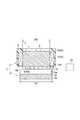
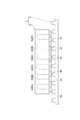
本実施形態に係るリニアモータ1は、例えば様々な製造装置又は加工装置等のFA機器において、テーブル送り等に利用される。図1及び図2に示すように、リニアモータ1は、互いに空隙を介して対向する電機子2及び固定子3を備える。固定子3は、電機子2との対向方向に直交するように延びる長尺形状を呈し、設置対象(例えばFA機器の本体部)に固定される。電機子2は、固定子3の長手方向に沿って移動自在となるように、リニアガイド(不図示)により支持される。電機子2は、駆動対象(例えばFA機器のテーブル)に固定される。リニアモータ1は、固定子3の長手方向に沿って、固定子3に対する電機子2の相対運動を発生させることで駆動対象を移送する。なお、電機子2が設置対象に固定され、固定子3が駆動対象に固定されてもよい。この場合、リニアモータ1は、電機子2に対する固定子3の相対運動を発生させることで駆動対象を移送する。 The
続いて、固定子3及び電機子2の構成について詳細に説明する。説明において、「上下」、「前後」及び「左右」は、電機子2側を上側とし、固定子3側を下側とし、固定子3の一端側を前側とした方向を意味する。 Then, the structure of the
固定子3は、ヨーク3aと複数の突極3bとを有する。ヨーク3aは、前後方向に沿って延びると共に左右方向に沿って広がった帯状を呈する。複数の突極3bは、前後方向に沿って並ぶと共に、それぞれヨーク3aから上側に突出する。突極3bは、左右方向に沿って延び、台形の断面形状を呈する。突極3bの断面形状は台形に限られず、例えば矩形又は半円形であってもよい。 The
固定子3は、例えば3%珪素鉄等の鉄系の軟磁性材料により構成される。固定子3は、珪素鋼板等の電磁鋼板を左右方向に沿って積層したものであってもよく、軟磁性複合材料(SMC)を圧縮成形したものであってもよく、鉄系の構造材により一体的に形成されたものであってもよい。 The
電機子2は、電機子コア4と、6セットの電機子巻線7と、12個の永久磁石8と、6個の磁界センサ10とを有する。 The
電機子コア4は、ヨーク5と、6箇所のティース6とを有する。ヨーク5は、前後方向に沿って延びると共に左右方向に沿って広がった平板状を呈する。6箇所のティース6は、前後方向に沿って並ぶと共にそれぞれヨーク5から下側に突出する。 The
電機子コア4は、例えば3%珪素鉄等の鉄系の軟磁性材料により構成される。電機子コア4は、珪素鋼板等の電磁鋼板を左右方向に沿って積層したものであってもよく、軟磁性複合材料(SMC)を圧縮成形したものであってもよい。 The
6セットの電機子巻線7は、6箇所のティース6にそれぞれ巻かれている。最前のティース6Aに巻かれた電機子巻線7Aと、前から3番目のティース6Cに巻かれた電機子巻線7Cと、前から5番目のティース6Eに巻かれた電機子巻線7Eとには、互いに位相が1/3周期ずれた3相の交流がそれぞれ供給される。以下、電機子巻線7Aに供給される交流を「U相交流」といい、電機子巻線7Cに供給される交流を「V相交流」といい、電機子巻線7Eに供給される交流を「W相交流」という。 Six sets of
前から2番目のティース6Bに巻かれた電機子巻線7Bと、前から4番目のティース6Dに巻かれた電機子巻線7Dと、前から6番目のティース6Fに巻かれた電機子巻線7Fとには、W相交流と、U相交流と、V相交流とがそれぞれ供給される。電機子巻線7D,7F,7Bへの交流の供給方向は、電機子巻線7A,7C,7Eへの交流の供給方向に対してそれぞれ逆向きである。 The armature winding 7B wound around the
電機子コア4及び電機子巻線7は、モールド材Pにより一体化され、電磁石ユニット9を構成している。モールド材P1は、例えばエポキシ系樹脂である。電磁石ユニット9は、前後方向に延びた直方体形状を呈する。電磁石ユニット9の下面9aは、ティース6の先端面(下端面)と略面一になっている。 The
12個の永久磁石8は、前後方向に沿って並んだ状態で、接着等により電磁石ユニット9の下面9aに固定されている。それぞれの永久磁石8は、左右方向に沿って延び、矩形の断面形状を呈する。6個の永久磁石8Aは、下側がS極、上側がN極となるように配置されている。残りの6個の永久磁石8Bは、下側がN極、上側がS極となるように配置されている。永久磁石8Aと永久磁石8Bとは交互に並んでおり、ティース6ごとに一対の永久磁石8A,8Bが位置している。すなわち、それぞれのティース6の先端側には、前後方向に沿って並ぶ一対の永久磁石8A,8Bが設けられている。 The twelve
図2及び図3に示すように、磁界センサ10は、左右方向(固定子3の幅方向)において永久磁石8の外側に配置されている。6個の磁界センサ10は、前後方向において、ティース6Dの先端側の永久磁石8A,8Bと、ティース6Eの先端側の永久磁石8A,8Bと、ティース6Fの先端側の永久磁石8A,8Bとにそれぞれ対応するように配置されている。すなわち、2個の磁界センサ10は、U相交流を受け入れる電機子巻線7Dに対応している。2個の磁界センサ10は、W相交流を受け入れる電機子巻線7Eに対応している。残りの2個の磁界センサ10は、V相交流を受け入れる電機子巻線7Fに対応している。このように、磁界センサ10は、3相交流の相ごとに2個ずつ配置されている。この状態で、磁界センサ10は電磁石ユニット9に固定されている。 As shown in FIGS. 2 and 3, the
磁界センサ10は、例えばホール素子又はホール素子を内蔵するホールICであり、磁界を検出する。磁界センサ10の感磁面10aは、上側及び下側に面する。感磁面10aは、磁界センサ10により検出可能な磁界の方向に交差する面である。 The
左右方向における突極3bの幅W1は、左右方向におけるティース6及び永久磁石8の幅W2より大きい。左右方向において、突極3bの端部は永久磁石8の端部より外側に張り出し、磁界センサ10の下方に位置している。磁界センサ10の感磁面10aは上側から突極3bに対向する。 The width W1 of the
このようなリニアモータ1では、電機子2の電機子コア4、電機子巻線7及び永久磁石8の協働により進行磁界が生じ、この進行磁界が突極3bに作用することで推力が発生する。この推力により、固定子3の長手方向に沿って電機子2及び固定子3の相対運動が生じる。 In such a
期待通りの推力を発生させるには、電機子2に対する突極3bの相対位置を検出し、突極3bの位置に合わせて進行磁界を発生させる必要がある。図4に示すように、永久磁石8により発生した磁界Mの一部は、磁界センサ10による検出対象としても用いられる。詳しくは、左右方向における永久磁石8の端部において発生した磁界Maが検出対象として用いられる。 In order to generate the expected thrust, it is necessary to detect the relative position of the
永久磁石8Bの端部においては、永久磁石8Bから下側に出る磁界Maが発生する。この磁界Maは、突極3bにより磁界センサ10側に導かれ、下側から上側に向かって磁界センサ10の感磁面10aを通過する。一方、永久磁石8Aの端部においては、下側から永久磁石8Aに入る磁界Maが発生する。この磁界Maは、突極3bにより磁界センサ10側に導かれ、上側から下側に向かって磁界センサ10の感磁面10aを通過する。 At the end of the
このように、検出対象の磁界は突極3bによって磁界センサ10側に導かれるので、突極3bが永久磁石8に近接するにつれて磁界センサ10により検出される磁界が強くなる。このため、磁界センサ10により検出される磁界の強さに基づいて、永久磁石8に対する突極3bの相対位置を検出できる。従って、磁界センサ10を用いた単純な構成で、電機子2に対する突極3bの相対位置を検出できる。なお、検出対象の磁界の発生に、進行磁界の発生用の永久磁石8が兼用されている。このことも、突極3bの相対位置を検出する構成の単純化に寄与している。 Thus, since the magnetic field to be detected is guided to the
磁界センサ10は、突極3bに空隙をもって対向するように配置されている。このため、永久磁石8により発生した磁界を突極3bによって更に効率よく磁界センサ10側に導き、永久磁石8に対する突極3bの相対位置をより高感度に検出できる。 The
なお、磁界センサ10を突極3bに対向させる形態は、上述したものに限られない。図5は、左右方向の外側から突極3bに対向するように磁界センサ10を配置した例を示している。この場合、左右方向における突極3bの幅は、ティース6及び永久磁石8の幅W2に比べ大きい必要はない。そこで、図5の例では、突極3bの幅W1はティース6及び永久磁石8の幅W2に対し同等となっている。磁界センサ10は、左右方向において突極3bの外側に位置すると共に、突極3bに対応する高さに位置する。磁界センサ10の感磁面10aは、左側及び右側に面する。この状態で、磁界センサ10は、連結部材11を介して電機子コア4に固定される。連結部材11は、例えば鉄系の軟磁性材料からなる。 In addition, the form which makes the
この例によれば、突極3bの側面を有効活用して、永久磁石8に対する突極3bの相対位置を検出できる。また、連結部材11を磁界の経路として利用できるので、永久磁石8により発生した磁界を更に効率よく磁界センサ10に導き、永久磁石8に対する突極3bの相対位置をより高感度に検出できる。 According to this example, the relative position of the
磁界センサ10は、前後方向において少なくとも一つの永久磁石8に対応するように配置されると共に、左右方向において当該永久磁石8の外側に配置されている。このため、電機子2及び固定子3が相対運動する方向において、磁界センサ10が電機子2の外側に張り出すことがないので、磁界センサ10の設置に伴う運動ストロークの低減を防止できる。 The
左右方向において、突極3bの端部は永久磁石8の端部より外側に張り出し、磁界センサ10は、電機子2側から突極3bに対向する。このため、磁界センサ10を永久磁石8の近傍に配置しつつ、突極3bに対向させることができる。従って、永久磁石8により発生した磁界を更に効率よく磁界センサ10に導き、永久磁石8に対する突極の相対位置をより高感度に検出できる。 In the left-right direction, the end of the
リニアモータ1は、前後方向に並ぶ複数の磁界センサ10を備える。このため、複数の磁界センサ10を用いることで、電機子2に対する突極3bの相対位置をより高精度に検出できる。 The
電機子2は、前後方向に並ぶ複数のティース6と、複数のティース6にそれぞれ巻かれ、複数相の交流をそれぞれ受け入れる複数の電機子巻線7とを有し、磁界センサ10は交流の相ごとに配置されている。このため、突極3bがいずれの相の電機子巻線7に近接しているのかを高精度に検出し、進行磁界をより確実に突極3bの位置に合わせることができる。 The
なお、磁界センサ10を交流の相ごとに配置する形態は、上述したものに限られない。図6は、3個の磁界センサ10を交流の相ごとに配置した例を示している。この例では、3個の磁界センサ10は、ティース6Cの先端側の永久磁石8Bと、ティース6Dの先端側の永久磁石8Aと、ティース6Eの先端側の永久磁石8Bとにそれぞれ対応するように配置されている。すなわち、1個の磁界センサ10は、V相交流を受け入れる電機子巻線7Cに対応している。1個の磁界センサ10は、U相交流を受け入れる電機子巻線7Dに対応している。残りの1個の磁界センサ10は、W相交流を受け入れる電機子巻線7Eに対応している。このように、磁界センサ10は、3相交流の相ごとに1個ずつ配置されている。 In addition, the form which arrange | positions the
リニアモータ1は、磁界センサ10の出力に基づいて、電機子2と固定子3との相対移動量を計測する計測部20を更に備えてもよい(図2参照)。計測部20は、例えば、磁界センサ10の出力を取得するポートを有するコンピュータにより構成可能である。この場合、相対移動量の計測専用の計測器を設ける必要がないので、リニアモータ1を利用する装置を単純化できる。 The
以上、本発明の好適な実施形態について説明してきたが、本発明は必ずしも上述した実施形態に限定されるものではなく、その要旨を逸脱しない範囲で様々な変更が可能である。例えば、磁界センサ10の数は1個であってもよい。また、磁界センサ10は、前後方向において永久磁石8に隣接するように配置されていてもよい。ティース6の数、電機子巻線7の数及び3相交流の割り当ては適宜変更可能である。永久磁石8の数及び配置も適宜変更可能である。電機子巻線7に供給する交流は、必ずしも3相に限られない。推力を継続的に発生させられる構成であれば、単層、2相又は4相以上であってもよい。 The preferred embodiments of the present invention have been described above. However, the present invention is not necessarily limited to the above-described embodiments, and various modifications can be made without departing from the scope of the present invention. For example, the number of
1…リニアモータ、2…電機子、3…固定子、3b…突極、4…電機子コア、6…ティース、7…電機子巻線、8…永久磁石、10…磁界センサ、11…連結部材、20…計測部。 DESCRIPTION OF
Claims (9)
Translated fromJapanese前記固定子は、
前記電機子との対向方向に交差するように延びた長尺形状を呈し、当該長尺形状の長手方向に沿って並び且つそれぞれ前記電機子側に突出する複数の突極を有し、
前記電機子は、
前記固定子側に突出するティースをなす電機子コアと、
前記ティースに巻かれた電機子巻線と、
前記固定子の前記長手方向に沿って並ぶように前記ティースの先端側に設けられ、前記電機子コア及び前記電機子巻線と協働して進行磁界を発生させる複数の永久磁石と、
前記永久磁石により発生して前記突極を通る磁界を検出する磁界センサとを有するリニアモータ。Comprising a stator and an armature facing each other through a gap,
The stator is
Presenting a long shape extending so as to intersect the facing direction of the armature, and having a plurality of salient poles arranged along the longitudinal direction of the long shape and projecting to the armature side,
The armature is
An armature core forming teeth protruding toward the stator side;
An armature winding wound around the teeth;
A plurality of permanent magnets that are provided on the tip side of the teeth so as to be aligned along the longitudinal direction of the stator,and generate a traveling magnetic field in cooperation with the armature core and the armature winding ;
And a magnetic field sensor that detects a magnetic field generated by the permanent magnet and passing through the salient pole.
Priority Applications (4)
| Application Number | Priority Date | Filing Date | Title |
|---|---|---|---|
| JP2013156803AJP5870973B2 (en) | 2013-07-29 | 2013-07-29 | Linear motor |
| US14/311,351US9270156B2 (en) | 2013-07-29 | 2014-06-23 | Linear motor |
| CN201410363742.0ACN104348332B (en) | 2013-07-29 | 2014-07-28 | Linear electric motors |
| KR1020140095551AKR101647189B1 (en) | 2013-07-29 | 2014-07-28 | Linear motor |
Applications Claiming Priority (1)
| Application Number | Priority Date | Filing Date | Title |
|---|---|---|---|
| JP2013156803AJP5870973B2 (en) | 2013-07-29 | 2013-07-29 | Linear motor |
Publications (2)
| Publication Number | Publication Date |
|---|---|
| JP2015027230A JP2015027230A (en) | 2015-02-05 |
| JP5870973B2true JP5870973B2 (en) | 2016-03-01 |
Family
ID=52389890
Family Applications (1)
| Application Number | Title | Priority Date | Filing Date |
|---|---|---|---|
| JP2013156803AActiveJP5870973B2 (en) | 2013-07-29 | 2013-07-29 | Linear motor |
Country Status (4)
| Country | Link |
|---|---|
| US (1) | US9270156B2 (en) |
| JP (1) | JP5870973B2 (en) |
| KR (1) | KR101647189B1 (en) |
| CN (1) | CN104348332B (en) |
Families Citing this family (184)
| Publication number | Priority date | Publication date | Assignee | Title |
|---|---|---|---|---|
| US9831718B2 (en) | 2013-07-25 | 2017-11-28 | Energous Corporation | TV with integrated wireless power transmitter |
| US10193396B1 (en) | 2014-05-07 | 2019-01-29 | Energous Corporation | Cluster management of transmitters in a wireless power transmission system |
| US9368020B1 (en) | 2013-05-10 | 2016-06-14 | Energous Corporation | Off-premises alert system and method for wireless power receivers in a wireless power network |
| US10218227B2 (en) | 2014-05-07 | 2019-02-26 | Energous Corporation | Compact PIFA antenna |
| US10224982B1 (en) | 2013-07-11 | 2019-03-05 | Energous Corporation | Wireless power transmitters for transmitting wireless power and tracking whether wireless power receivers are within authorized locations |
| US9900057B2 (en) | 2012-07-06 | 2018-02-20 | Energous Corporation | Systems and methods for assigning groups of antenas of a wireless power transmitter to different wireless power receivers, and determining effective phases to use for wirelessly transmitting power using the assigned groups of antennas |
| US9871398B1 (en) | 2013-07-01 | 2018-01-16 | Energous Corporation | Hybrid charging method for wireless power transmission based on pocket-forming |
| US9853458B1 (en) | 2014-05-07 | 2017-12-26 | Energous Corporation | Systems and methods for device and power receiver pairing |
| US9853692B1 (en) | 2014-05-23 | 2017-12-26 | Energous Corporation | Systems and methods for wireless power transmission |
| US10050462B1 (en) | 2013-08-06 | 2018-08-14 | Energous Corporation | Social power sharing for mobile devices based on pocket-forming |
| US9787103B1 (en) | 2013-08-06 | 2017-10-10 | Energous Corporation | Systems and methods for wirelessly delivering power to electronic devices that are unable to communicate with a transmitter |
| US10090886B1 (en) | 2014-07-14 | 2018-10-02 | Energous Corporation | System and method for enabling automatic charging schedules in a wireless power network to one or more devices |
| US11502551B2 (en) | 2012-07-06 | 2022-11-15 | Energous Corporation | Wirelessly charging multiple wireless-power receivers using different subsets of an antenna array to focus energy at different locations |
| US9867062B1 (en) | 2014-07-21 | 2018-01-09 | Energous Corporation | System and methods for using a remote server to authorize a receiving device that has requested wireless power and to determine whether another receiving device should request wireless power in a wireless power transmission system |
| US9887584B1 (en) | 2014-08-21 | 2018-02-06 | Energous Corporation | Systems and methods for a configuration web service to provide configuration of a wireless power transmitter within a wireless power transmission system |
| US10199835B2 (en) | 2015-12-29 | 2019-02-05 | Energous Corporation | Radar motion detection using stepped frequency in wireless power transmission system |
| US9876648B2 (en) | 2014-08-21 | 2018-01-23 | Energous Corporation | System and method to control a wireless power transmission system by configuration of wireless power transmission control parameters |
| US10008889B2 (en) | 2014-08-21 | 2018-06-26 | Energous Corporation | Method for automatically testing the operational status of a wireless power receiver in a wireless power transmission system |
| US9948135B2 (en) | 2015-09-22 | 2018-04-17 | Energous Corporation | Systems and methods for identifying sensitive objects in a wireless charging transmission field |
| US9954374B1 (en) | 2014-05-23 | 2018-04-24 | Energous Corporation | System and method for self-system analysis for detecting a fault in a wireless power transmission Network |
| US10211674B1 (en) | 2013-06-12 | 2019-02-19 | Energous Corporation | Wireless charging using selected reflectors |
| US10141791B2 (en) | 2014-05-07 | 2018-11-27 | Energous Corporation | Systems and methods for controlling communications during wireless transmission of power using application programming interfaces |
| US9793758B2 (en) | 2014-05-23 | 2017-10-17 | Energous Corporation | Enhanced transmitter using frequency control for wireless power transmission |
| US9843213B2 (en) | 2013-08-06 | 2017-12-12 | Energous Corporation | Social power sharing for mobile devices based on pocket-forming |
| US9859797B1 (en) | 2014-05-07 | 2018-01-02 | Energous Corporation | Synchronous rectifier design for wireless power receiver |
| US9806564B2 (en) | 2014-05-07 | 2017-10-31 | Energous Corporation | Integrated rectifier and boost converter for wireless power transmission |
| US9991741B1 (en) | 2014-07-14 | 2018-06-05 | Energous Corporation | System for tracking and reporting status and usage information in a wireless power management system |
| US9143000B2 (en) | 2012-07-06 | 2015-09-22 | Energous Corporation | Portable wireless charging pad |
| US9825674B1 (en) | 2014-05-23 | 2017-11-21 | Energous Corporation | Enhanced transmitter that selects configurations of antenna elements for performing wireless power transmission and receiving functions |
| US10038337B1 (en) | 2013-09-16 | 2018-07-31 | Energous Corporation | Wireless power supply for rescue devices |
| US10291055B1 (en) | 2014-12-29 | 2019-05-14 | Energous Corporation | Systems and methods for controlling far-field wireless power transmission based on battery power levels of a receiving device |
| US10256657B2 (en) | 2015-12-24 | 2019-04-09 | Energous Corporation | Antenna having coaxial structure for near field wireless power charging |
| US10992187B2 (en) | 2012-07-06 | 2021-04-27 | Energous Corporation | System and methods of using electromagnetic waves to wirelessly deliver power to electronic devices |
| US10199849B1 (en) | 2014-08-21 | 2019-02-05 | Energous Corporation | Method for automatically testing the operational status of a wireless power receiver in a wireless power transmission system |
| US10063064B1 (en) | 2014-05-23 | 2018-08-28 | Energous Corporation | System and method for generating a power receiver identifier in a wireless power network |
| US9906065B2 (en) | 2012-07-06 | 2018-02-27 | Energous Corporation | Systems and methods of transmitting power transmission waves based on signals received at first and second subsets of a transmitter's antenna array |
| US10381880B2 (en) | 2014-07-21 | 2019-08-13 | Energous Corporation | Integrated antenna structure arrays for wireless power transmission |
| US9923386B1 (en) | 2012-07-06 | 2018-03-20 | Energous Corporation | Systems and methods for wireless power transmission by modifying a number of antenna elements used to transmit power waves to a receiver |
| US10263432B1 (en) | 2013-06-25 | 2019-04-16 | Energous Corporation | Multi-mode transmitter with an antenna array for delivering wireless power and providing Wi-Fi access |
| US9899873B2 (en) | 2014-05-23 | 2018-02-20 | Energous Corporation | System and method for generating a power receiver identifier in a wireless power network |
| US9973021B2 (en) | 2012-07-06 | 2018-05-15 | Energous Corporation | Receivers for wireless power transmission |
| US20140008993A1 (en) | 2012-07-06 | 2014-01-09 | DvineWave Inc. | Methodology for pocket-forming |
| US10224758B2 (en) | 2013-05-10 | 2019-03-05 | Energous Corporation | Wireless powering of electronic devices with selective delivery range |
| US9438045B1 (en) | 2013-05-10 | 2016-09-06 | Energous Corporation | Methods and systems for maximum power point transfer in receivers |
| US9876379B1 (en) | 2013-07-11 | 2018-01-23 | Energous Corporation | Wireless charging and powering of electronic devices in a vehicle |
| US9124125B2 (en) | 2013-05-10 | 2015-09-01 | Energous Corporation | Wireless power transmission with selective range |
| US10124754B1 (en) | 2013-07-19 | 2018-11-13 | Energous Corporation | Wireless charging and powering of electronic sensors in a vehicle |
| US9843201B1 (en) | 2012-07-06 | 2017-12-12 | Energous Corporation | Wireless power transmitter that selects antenna sets for transmitting wireless power to a receiver based on location of the receiver, and methods of use thereof |
| US9912199B2 (en) | 2012-07-06 | 2018-03-06 | Energous Corporation | Receivers for wireless power transmission |
| US10205239B1 (en) | 2014-05-07 | 2019-02-12 | Energous Corporation | Compact PIFA antenna |
| US9876394B1 (en) | 2014-05-07 | 2018-01-23 | Energous Corporation | Boost-charger-boost system for enhanced power delivery |
| US9824815B2 (en) | 2013-05-10 | 2017-11-21 | Energous Corporation | Wireless charging and powering of healthcare gadgets and sensors |
| US9252628B2 (en) | 2013-05-10 | 2016-02-02 | Energous Corporation | Laptop computer as a transmitter for wireless charging |
| US9939864B1 (en) | 2014-08-21 | 2018-04-10 | Energous Corporation | System and method to control a wireless power transmission system by configuration of wireless power transmission control parameters |
| US10186913B2 (en) | 2012-07-06 | 2019-01-22 | Energous Corporation | System and methods for pocket-forming based on constructive and destructive interferences to power one or more wireless power receivers using a wireless power transmitter including a plurality of antennas |
| US10312715B2 (en) | 2015-09-16 | 2019-06-04 | Energous Corporation | Systems and methods for wireless power charging |
| US10270261B2 (en) | 2015-09-16 | 2019-04-23 | Energous Corporation | Systems and methods of object detection in wireless power charging systems |
| US10063106B2 (en) | 2014-05-23 | 2018-08-28 | Energous Corporation | System and method for a self-system analysis in a wireless power transmission network |
| US10206185B2 (en) | 2013-05-10 | 2019-02-12 | Energous Corporation | System and methods for wireless power transmission to an electronic device in accordance with user-defined restrictions |
| US9847679B2 (en) | 2014-05-07 | 2017-12-19 | Energous Corporation | System and method for controlling communication between wireless power transmitter managers |
| US9882430B1 (en) | 2014-05-07 | 2018-01-30 | Energous Corporation | Cluster management of transmitters in a wireless power transmission system |
| US10141768B2 (en) | 2013-06-03 | 2018-11-27 | Energous Corporation | Systems and methods for maximizing wireless power transfer efficiency by instructing a user to change a receiver device's position |
| US9966765B1 (en) | 2013-06-25 | 2018-05-08 | Energous Corporation | Multi-mode transmitter |
| US10230266B1 (en) | 2014-02-06 | 2019-03-12 | Energous Corporation | Wireless power receivers that communicate status data indicating wireless power transmission effectiveness with a transmitter using a built-in communications component of a mobile device, and methods of use thereof |
| US9941707B1 (en) | 2013-07-19 | 2018-04-10 | Energous Corporation | Home base station for multiple room coverage with multiple transmitters |
| US10103582B2 (en) | 2012-07-06 | 2018-10-16 | Energous Corporation | Transmitters for wireless power transmission |
| US10965164B2 (en) | 2012-07-06 | 2021-03-30 | Energous Corporation | Systems and methods of wirelessly delivering power to a receiver device |
| US10223717B1 (en) | 2014-05-23 | 2019-03-05 | Energous Corporation | Systems and methods for payment-based authorization of wireless power transmission service |
| US10291066B1 (en) | 2014-05-07 | 2019-05-14 | Energous Corporation | Power transmission control systems and methods |
| US20150326070A1 (en) | 2014-05-07 | 2015-11-12 | Energous Corporation | Methods and Systems for Maximum Power Point Transfer in Receivers |
| US10211682B2 (en) | 2014-05-07 | 2019-02-19 | Energous Corporation | Systems and methods for controlling operation of a transmitter of a wireless power network based on user instructions received from an authenticated computing device powered or charged by a receiver of the wireless power network |
| US9899861B1 (en) | 2013-10-10 | 2018-02-20 | Energous Corporation | Wireless charging methods and systems for game controllers, based on pocket-forming |
| US10148097B1 (en) | 2013-11-08 | 2018-12-04 | Energous Corporation | Systems and methods for using a predetermined number of communication channels of a wireless power transmitter to communicate with different wireless power receivers |
| US10128693B2 (en) | 2014-07-14 | 2018-11-13 | Energous Corporation | System and method for providing health safety in a wireless power transmission system |
| US9891669B2 (en) | 2014-08-21 | 2018-02-13 | Energous Corporation | Systems and methods for a configuration web service to provide configuration of a wireless power transmitter within a wireless power transmission system |
| US10211680B2 (en) | 2013-07-19 | 2019-02-19 | Energous Corporation | Method for 3 dimensional pocket-forming |
| US10992185B2 (en) | 2012-07-06 | 2021-04-27 | Energous Corporation | Systems and methods of using electromagnetic waves to wirelessly deliver power to game controllers |
| US9812890B1 (en) | 2013-07-11 | 2017-11-07 | Energous Corporation | Portable wireless charging pad |
| US12057715B2 (en) | 2012-07-06 | 2024-08-06 | Energous Corporation | Systems and methods of wirelessly delivering power to a wireless-power receiver device in response to a change of orientation of the wireless-power receiver device |
| US9887739B2 (en) | 2012-07-06 | 2018-02-06 | Energous Corporation | Systems and methods for wireless power transmission by comparing voltage levels associated with power waves transmitted by antennas of a plurality of antennas of a transmitter to determine appropriate phase adjustments for the power waves |
| US10439448B2 (en) | 2014-08-21 | 2019-10-08 | Energous Corporation | Systems and methods for automatically testing the communication between wireless power transmitter and wireless power receiver |
| US9882427B2 (en) | 2013-05-10 | 2018-01-30 | Energous Corporation | Wireless power delivery using a base station to control operations of a plurality of wireless power transmitters |
| US9859756B2 (en) | 2012-07-06 | 2018-01-02 | Energous Corporation | Transmittersand methods for adjusting wireless power transmission based on information from receivers |
| US9941747B2 (en) | 2014-07-14 | 2018-04-10 | Energous Corporation | System and method for manually selecting and deselecting devices to charge in a wireless power network |
| US10243414B1 (en) | 2014-05-07 | 2019-03-26 | Energous Corporation | Wearable device with wireless power and payload receiver |
| US10128699B2 (en) | 2014-07-14 | 2018-11-13 | Energous Corporation | Systems and methods of providing wireless power using receiver device sensor inputs |
| US10090699B1 (en) | 2013-11-01 | 2018-10-02 | Energous Corporation | Wireless powered house |
| US10063105B2 (en) | 2013-07-11 | 2018-08-28 | Energous Corporation | Proximity transmitters for wireless power charging systems |
| US9893768B2 (en) | 2012-07-06 | 2018-02-13 | Energous Corporation | Methodology for multiple pocket-forming |
| US9893554B2 (en) | 2014-07-14 | 2018-02-13 | Energous Corporation | System and method for providing health safety in a wireless power transmission system |
| US9538382B2 (en) | 2013-05-10 | 2017-01-03 | Energous Corporation | System and method for smart registration of wireless power receivers in a wireless power network |
| US9419443B2 (en) | 2013-05-10 | 2016-08-16 | Energous Corporation | Transducer sound arrangement for pocket-forming |
| US9866279B2 (en) | 2013-05-10 | 2018-01-09 | Energous Corporation | Systems and methods for selecting which power transmitter should deliver wireless power to a receiving device in a wireless power delivery network |
| US9537357B2 (en) | 2013-05-10 | 2017-01-03 | Energous Corporation | Wireless sound charging methods and systems for game controllers, based on pocket-forming |
| US9819230B2 (en) | 2014-05-07 | 2017-11-14 | Energous Corporation | Enhanced receiver for wireless power transmission |
| US10103552B1 (en) | 2013-06-03 | 2018-10-16 | Energous Corporation | Protocols for authenticated wireless power transmission |
| US10003211B1 (en) | 2013-06-17 | 2018-06-19 | Energous Corporation | Battery life of portable electronic devices |
| US10021523B2 (en) | 2013-07-11 | 2018-07-10 | Energous Corporation | Proximity transmitters for wireless power charging systems |
| US9979440B1 (en) | 2013-07-25 | 2018-05-22 | Energous Corporation | Antenna tile arrangements configured to operate as one functional unit |
| US9935482B1 (en) | 2014-02-06 | 2018-04-03 | Energous Corporation | Wireless power transmitters that transmit at determined times based on power availability and consumption at a receiving mobile device |
| US10075017B2 (en) | 2014-02-06 | 2018-09-11 | Energous Corporation | External or internal wireless power receiver with spaced-apart antenna elements for charging or powering mobile devices using wirelessly delivered power |
| US9966784B2 (en) | 2014-06-03 | 2018-05-08 | Energous Corporation | Systems and methods for extending battery life of portable electronic devices charged by sound |
| US10158257B2 (en) | 2014-05-01 | 2018-12-18 | Energous Corporation | System and methods for using sound waves to wirelessly deliver power to electronic devices |
| US10153653B1 (en) | 2014-05-07 | 2018-12-11 | Energous Corporation | Systems and methods for using application programming interfaces to control communications between a transmitter and a receiver |
| US10170917B1 (en) | 2014-05-07 | 2019-01-01 | Energous Corporation | Systems and methods for managing and controlling a wireless power network by establishing time intervals during which receivers communicate with a transmitter |
| US10153645B1 (en) | 2014-05-07 | 2018-12-11 | Energous Corporation | Systems and methods for designating a master power transmitter in a cluster of wireless power transmitters |
| US9973008B1 (en) | 2014-05-07 | 2018-05-15 | Energous Corporation | Wireless power receiver with boost converters directly coupled to a storage element |
| US9876536B1 (en) | 2014-05-23 | 2018-01-23 | Energous Corporation | Systems and methods for assigning groups of antennas to transmit wireless power to different wireless power receivers |
| US10068703B1 (en) | 2014-07-21 | 2018-09-04 | Energous Corporation | Integrated miniature PIFA with artificial magnetic conductor metamaterials |
| US9871301B2 (en) | 2014-07-21 | 2018-01-16 | Energous Corporation | Integrated miniature PIFA with artificial magnetic conductor metamaterials |
| US10116143B1 (en) | 2014-07-21 | 2018-10-30 | Energous Corporation | Integrated antenna arrays for wireless power transmission |
| US9965009B1 (en) | 2014-08-21 | 2018-05-08 | Energous Corporation | Systems and methods for assigning a power receiver to individual power transmitters based on location of the power receiver |
| US10122415B2 (en) | 2014-12-27 | 2018-11-06 | Energous Corporation | Systems and methods for assigning a set of antennas of a wireless power transmitter to a wireless power receiver based on a location of the wireless power receiver |
| US9893535B2 (en) | 2015-02-13 | 2018-02-13 | Energous Corporation | Systems and methods for determining optimal charging positions to maximize efficiency of power received from wirelessly delivered sound wave energy |
| US10523033B2 (en) | 2015-09-15 | 2019-12-31 | Energous Corporation | Receiver devices configured to determine location within a transmission field |
| US12283828B2 (en) | 2015-09-15 | 2025-04-22 | Energous Corporation | Receiver devices configured to determine location within a transmission field |
| US9906275B2 (en) | 2015-09-15 | 2018-02-27 | Energous Corporation | Identifying receivers in a wireless charging transmission field |
| US10158259B1 (en) | 2015-09-16 | 2018-12-18 | Energous Corporation | Systems and methods for identifying receivers in a transmission field by transmitting exploratory power waves towards different segments of a transmission field |
| US10778041B2 (en) | 2015-09-16 | 2020-09-15 | Energous Corporation | Systems and methods for generating power waves in a wireless power transmission system |
| US9893538B1 (en) | 2015-09-16 | 2018-02-13 | Energous Corporation | Systems and methods of object detection in wireless power charging systems |
| US9871387B1 (en) | 2015-09-16 | 2018-01-16 | Energous Corporation | Systems and methods of object detection using one or more video cameras in wireless power charging systems |
| US9941752B2 (en) | 2015-09-16 | 2018-04-10 | Energous Corporation | Systems and methods of object detection in wireless power charging systems |
| US10186893B2 (en) | 2015-09-16 | 2019-01-22 | Energous Corporation | Systems and methods for real time or near real time wireless communications between a wireless power transmitter and a wireless power receiver |
| US11710321B2 (en) | 2015-09-16 | 2023-07-25 | Energous Corporation | Systems and methods of object detection in wireless power charging systems |
| US10199850B2 (en) | 2015-09-16 | 2019-02-05 | Energous Corporation | Systems and methods for wirelessly transmitting power from a transmitter to a receiver by determining refined locations of the receiver in a segmented transmission field associated with the transmitter |
| US10211685B2 (en) | 2015-09-16 | 2019-02-19 | Energous Corporation | Systems and methods for real or near real time wireless communications between a wireless power transmitter and a wireless power receiver |
| US10008875B1 (en) | 2015-09-16 | 2018-06-26 | Energous Corporation | Wireless power transmitter configured to transmit power waves to a predicted location of a moving wireless power receiver |
| US10128686B1 (en) | 2015-09-22 | 2018-11-13 | Energous Corporation | Systems and methods for identifying receiver locations using sensor technologies |
| US10020678B1 (en) | 2015-09-22 | 2018-07-10 | Energous Corporation | Systems and methods for selecting antennas to generate and transmit power transmission waves |
| US10135295B2 (en) | 2015-09-22 | 2018-11-20 | Energous Corporation | Systems and methods for nullifying energy levels for wireless power transmission waves |
| US10033222B1 (en) | 2015-09-22 | 2018-07-24 | Energous Corporation | Systems and methods for determining and generating a waveform for wireless power transmission waves |
| US10135294B1 (en) | 2015-09-22 | 2018-11-20 | Energous Corporation | Systems and methods for preconfiguring transmission devices for power wave transmissions based on location data of one or more receivers |
| US10027168B2 (en) | 2015-09-22 | 2018-07-17 | Energous Corporation | Systems and methods for generating and transmitting wireless power transmission waves using antennas having a spacing that is selected by the transmitter |
| US10153660B1 (en) | 2015-09-22 | 2018-12-11 | Energous Corporation | Systems and methods for preconfiguring sensor data for wireless charging systems |
| US10050470B1 (en) | 2015-09-22 | 2018-08-14 | Energous Corporation | Wireless power transmission device having antennas oriented in three dimensions |
| US10333332B1 (en) | 2015-10-13 | 2019-06-25 | Energous Corporation | Cross-polarized dipole antenna |
| US10734717B2 (en) | 2015-10-13 | 2020-08-04 | Energous Corporation | 3D ceramic mold antenna |
| US9899744B1 (en) | 2015-10-28 | 2018-02-20 | Energous Corporation | Antenna for wireless charging systems |
| US9853485B2 (en) | 2015-10-28 | 2017-12-26 | Energous Corporation | Antenna for wireless charging systems |
| US10135112B1 (en) | 2015-11-02 | 2018-11-20 | Energous Corporation | 3D antenna mount |
| US10063108B1 (en) | 2015-11-02 | 2018-08-28 | Energous Corporation | Stamped three-dimensional antenna |
| US10027180B1 (en) | 2015-11-02 | 2018-07-17 | Energous Corporation | 3D triple linear antenna that acts as heat sink |
| US10038332B1 (en) | 2015-12-24 | 2018-07-31 | Energous Corporation | Systems and methods of wireless power charging through multiple receiving devices |
| US10116162B2 (en) | 2015-12-24 | 2018-10-30 | Energous Corporation | Near field transmitters with harmonic filters for wireless power charging |
| US10027159B2 (en) | 2015-12-24 | 2018-07-17 | Energous Corporation | Antenna for transmitting wireless power signals |
| US11863001B2 (en) | 2015-12-24 | 2024-01-02 | Energous Corporation | Near-field antenna for wireless power transmission with antenna elements that follow meandering patterns |
| US10256677B2 (en) | 2016-12-12 | 2019-04-09 | Energous Corporation | Near-field RF charging pad with adaptive loading to efficiently charge an electronic device at any position on the pad |
| US10079515B2 (en) | 2016-12-12 | 2018-09-18 | Energous Corporation | Near-field RF charging pad with multi-band antenna element with adaptive loading to efficiently charge an electronic device at any position on the pad |
| US10320446B2 (en) | 2015-12-24 | 2019-06-11 | Energous Corporation | Miniaturized highly-efficient designs for near-field power transfer system |
| US10008886B2 (en) | 2015-12-29 | 2018-06-26 | Energous Corporation | Modular antennas with heat sinks in wireless power transmission systems |
| US10923954B2 (en) | 2016-11-03 | 2021-02-16 | Energous Corporation | Wireless power receiver with a synchronous rectifier |
| KR102185600B1 (en) | 2016-12-12 | 2020-12-03 | 에너저스 코포레이션 | A method of selectively activating antenna zones of a near field charging pad to maximize transmitted wireless power |
| US10439442B2 (en) | 2017-01-24 | 2019-10-08 | Energous Corporation | Microstrip antennas for wireless power transmitters |
| US10680319B2 (en) | 2017-01-06 | 2020-06-09 | Energous Corporation | Devices and methods for reducing mutual coupling effects in wireless power transmission systems |
| US10389161B2 (en) | 2017-03-15 | 2019-08-20 | Energous Corporation | Surface mount dielectric antennas for wireless power transmitters |
| US11011942B2 (en) | 2017-03-30 | 2021-05-18 | Energous Corporation | Flat antennas having two or more resonant frequencies for use in wireless power transmission systems |
| US10511097B2 (en) | 2017-05-12 | 2019-12-17 | Energous Corporation | Near-field antennas for accumulating energy at a near-field distance with minimal far-field gain |
| US12074452B2 (en) | 2017-05-16 | 2024-08-27 | Wireless Electrical Grid Lan, Wigl Inc. | Networked wireless charging system |
| US12074460B2 (en) | 2017-05-16 | 2024-08-27 | Wireless Electrical Grid Lan, Wigl Inc. | Rechargeable wireless power bank and method of using |
| US11462949B2 (en) | 2017-05-16 | 2022-10-04 | Wireless electrical Grid LAN, WiGL Inc | Wireless charging method and system |
| US10848853B2 (en) | 2017-06-23 | 2020-11-24 | Energous Corporation | Systems, methods, and devices for utilizing a wire of a sound-producing device as an antenna for receipt of wirelessly delivered power |
| US10122219B1 (en) | 2017-10-10 | 2018-11-06 | Energous Corporation | Systems, methods, and devices for using a battery as a antenna for receiving wirelessly delivered power from radio frequency power waves |
| US11342798B2 (en) | 2017-10-30 | 2022-05-24 | Energous Corporation | Systems and methods for managing coexistence of wireless-power signals and data signals operating in a same frequency band |
| US10615647B2 (en) | 2018-02-02 | 2020-04-07 | Energous Corporation | Systems and methods for detecting wireless power receivers and other objects at a near-field charging pad |
| US11159057B2 (en) | 2018-03-14 | 2021-10-26 | Energous Corporation | Loop antennas with selectively-activated feeds to control propagation patterns of wireless power signals |
| US11515732B2 (en) | 2018-06-25 | 2022-11-29 | Energous Corporation | Power wave transmission techniques to focus wirelessly delivered power at a receiving device |
| US11437735B2 (en) | 2018-11-14 | 2022-09-06 | Energous Corporation | Systems for receiving electromagnetic energy using antennas that are minimally affected by the presence of the human body |
| US11539243B2 (en) | 2019-01-28 | 2022-12-27 | Energous Corporation | Systems and methods for miniaturized antenna for wireless power transmissions |
| EP3921945A1 (en) | 2019-02-06 | 2021-12-15 | Energous Corporation | Systems and methods of estimating optimal phases to use for individual antennas in an antenna array |
| US12155231B2 (en) | 2019-04-09 | 2024-11-26 | Energous Corporation | Asymmetric spiral antennas for wireless power transmission and reception |
| CN114731061A (en) | 2019-09-20 | 2022-07-08 | 艾诺格思公司 | Classifying and detecting foreign objects using a power amplifier controller integrated circuit in a wireless power transmission system |
| US11381118B2 (en) | 2019-09-20 | 2022-07-05 | Energous Corporation | Systems and methods for machine learning based foreign object detection for wireless power transmission |
| WO2021055901A1 (en) | 2019-09-20 | 2021-03-25 | Energous Corporation | Asymmetric spiral antennas with parasitic elements for wireless power transmission |
| WO2021055898A1 (en) | 2019-09-20 | 2021-03-25 | Energous Corporation | Systems and methods for machine learning based foreign object detection for wireless power transmission |
| WO2021055899A1 (en) | 2019-09-20 | 2021-03-25 | Energous Corporation | Systems and methods of protecting wireless power receivers using multiple rectifiers and establishing in-band communications using multiple rectifiers |
| US11355966B2 (en) | 2019-12-13 | 2022-06-07 | Energous Corporation | Charging pad with guiding contours to align an electronic device on the charging pad and efficiently transfer near-field radio-frequency energy to the electronic device |
| US10985617B1 (en) | 2019-12-31 | 2021-04-20 | Energous Corporation | System for wirelessly transmitting energy at a near-field distance without using beam-forming control |
| US11799324B2 (en) | 2020-04-13 | 2023-10-24 | Energous Corporation | Wireless-power transmitting device for creating a uniform near-field charging area |
| CN111600445B (en)* | 2020-05-29 | 2021-10-26 | 北京机械设备研究所 | Linear motor rotor position signal processing method, device and system and storage medium |
| US11469629B2 (en) | 2020-08-12 | 2022-10-11 | Energous Corporation | Systems and methods for secure wireless transmission of power using unidirectional communication signals from a wireless-power-receiving device |
| US12306285B2 (en) | 2020-12-01 | 2025-05-20 | Energous Corporation | Systems and methods for using one or more sensors to detect and classify objects in a keep-out zone of a wireless-power transmission field, and antennas with integrated sensor arrangements |
| US11916398B2 (en) | 2021-12-29 | 2024-02-27 | Energous Corporation | Small form-factor devices with integrated and modular harvesting receivers, and shelving-mounted wireless-power transmitters for use therewith |
| US12142939B2 (en) | 2022-05-13 | 2024-11-12 | Energous Corporation | Integrated wireless-power-transmission platform designed to operate in multiple bands, and multi-band antennas for use therewith |
| KR102850709B1 (en)* | 2022-12-29 | 2025-08-26 | 주식회사 에스에프에이 | In-line system for manufacturing secondary battery |
Family Cites Families (19)
| Publication number | Priority date | Publication date | Assignee | Title |
|---|---|---|---|---|
| JPS6115560A (en)* | 1984-06-28 | 1986-01-23 | Toshiro Higuchi | linear step motor |
| JPS62114462A (en)* | 1985-11-11 | 1987-05-26 | Matsushita Electric Ind Co Ltd | linear motor |
| JPS6321483U (en)* | 1986-07-23 | 1988-02-12 | ||
| JPS63228954A (en)* | 1987-03-18 | 1988-09-22 | Amada Co Ltd | Secondary side stator for linear pulse motor |
| JPH07107732A (en)* | 1993-09-29 | 1995-04-21 | Oriental Motor Co Ltd | Linear motor |
| CN1038289C (en)* | 1994-09-29 | 1998-05-06 | 东方电机株式会社 | Linear motor |
| JPH1066328A (en) | 1996-08-23 | 1998-03-06 | Yamaha Motor Co Ltd | Linear motor |
| DE102004045992A1 (en)* | 2004-09-22 | 2006-04-06 | Siemens Ag | Electric machine |
| DE102005007489A1 (en)* | 2005-02-17 | 2006-08-24 | Siemens Ag | Woodworking machine with linear direct drive |
| DE102005017498B4 (en)* | 2005-04-15 | 2010-07-08 | Siemens Ag | Synchronous linear motor with contactless scanning of the tooth structure of the abutment |
| DE102006016503A1 (en)* | 2006-04-07 | 2007-10-18 | Siemens Ag | Encoder device for an electrical machine |
| DE102006038162A1 (en)* | 2006-08-16 | 2008-02-21 | Siemens Ag | Electric motor with measuring system for position or movement |
| JP5289799B2 (en) | 2008-03-07 | 2013-09-11 | オークマ株式会社 | Linear motor |
| KR100984488B1 (en)* | 2008-06-04 | 2010-10-01 | 한국과학기술연구원 | Linear motor |
| JP2010035287A (en)* | 2008-07-25 | 2010-02-12 | Hitachi Ltd | Cylindrical linear motor, and electromagnetic suspension and motor-driven power steering device using the same |
| JP2011061995A (en)* | 2009-09-10 | 2011-03-24 | Nikon Corp | Linear motor and position detecting method of linear motor |
| JP5574173B2 (en)* | 2010-03-18 | 2014-08-20 | 株式会社安川電機 | Permanent magnet type synchronous linear motor and table feeding device using the same |
| JP5488836B2 (en) | 2011-02-23 | 2014-05-14 | 株式会社安川電機 | Linear motor |
| JP5739254B2 (en)* | 2011-07-08 | 2015-06-24 | オークマ株式会社 | Control device for synchronous motor |
- 2013
- 2013-07-29JPJP2013156803Apatent/JP5870973B2/enactiveActive
- 2014
- 2014-06-23USUS14/311,351patent/US9270156B2/enactiveActive
- 2014-07-28KRKR1020140095551Apatent/KR101647189B1/enactiveActive
- 2014-07-28CNCN201410363742.0Apatent/CN104348332B/enactiveActive
Also Published As
| Publication number | Publication date |
|---|---|
| CN104348332A (en) | 2015-02-11 |
| JP2015027230A (en) | 2015-02-05 |
| CN104348332B (en) | 2017-06-16 |
| KR101647189B1 (en) | 2016-08-09 |
| US20150028697A1 (en) | 2015-01-29 |
| US9270156B2 (en) | 2016-02-23 |
| KR20150014392A (en) | 2015-02-06 |
Similar Documents
| Publication | Publication Date | Title |
|---|---|---|
| JP5870973B2 (en) | Linear motor | |
| JP5509049B2 (en) | Magnetic encoder, actuator | |
| US9118237B2 (en) | Mover for a linear motor and linear motor | |
| US10411527B2 (en) | Linear motor | |
| JP5418558B2 (en) | Linear motor stator and linear motor | |
| JPWO2014054098A1 (en) | Electric drive | |
| JP2015111080A (en) | Bus bar module | |
| JP5527426B2 (en) | Linear motor | |
| JPWO2016056135A1 (en) | Current detection device and current detection method | |
| JP2017525329A (en) | Electric linear machine | |
| JP2015027234A (en) | Linear motor | |
| WO2013047610A1 (en) | Actuator | |
| JP2015111079A (en) | Bus bar module | |
| US7808132B2 (en) | Electric machine comprising a screened leakage-field-sensitive sensor | |
| JP2010115020A (en) | Position sensor unit and three-phase ac linear motor | |
| CN112224844A (en) | Linear transport apparatus, control method, and medium | |
| JP6761186B2 (en) | Linear motor | |
| JP5403008B2 (en) | Linear motor armature and linear motor | |
| TWI343166B (en) | ||
| JP2007209176A (en) | Three-phase linear motor | |
| JP2018169188A (en) | Current detection device | |
| JP2012100423A (en) | Linear motor | |
| JP2016082653A (en) | Linear motor and linear motor device |
Legal Events
| Date | Code | Title | Description |
|---|---|---|---|
| A621 | Written request for application examination | Free format text:JAPANESE INTERMEDIATE CODE: A621 Effective date:20150115 | |
| A977 | Report on retrieval | Free format text:JAPANESE INTERMEDIATE CODE: A971007 Effective date:20150526 | |
| A131 | Notification of reasons for refusal | Free format text:JAPANESE INTERMEDIATE CODE: A131 Effective date:20150602 | |
| A521 | Request for written amendment filed | Free format text:JAPANESE INTERMEDIATE CODE: A523 Effective date:20150630 | |
| TRDD | Decision of grant or rejection written | ||
| A01 | Written decision to grant a patent or to grant a registration (utility model) | Free format text:JAPANESE INTERMEDIATE CODE: A01 Effective date:20151215 | |
| A61 | First payment of annual fees (during grant procedure) | Free format text:JAPANESE INTERMEDIATE CODE: A61 Effective date:20151228 | |
| R150 | Certificate of patent or registration of utility model | Ref document number:5870973 Country of ref document:JP Free format text:JAPANESE INTERMEDIATE CODE: R150 | |
| R250 | Receipt of annual fees | Free format text:JAPANESE INTERMEDIATE CODE: R250 |