JP5870880B2 - Structure for determining the thickness of the hard coat layer - Google Patents
Structure for determining the thickness of the hard coat layerDownload PDFInfo
- Publication number
- JP5870880B2 JP5870880B2JP2012189895AJP2012189895AJP5870880B2JP 5870880 B2JP5870880 B2JP 5870880B2JP 2012189895 AJP2012189895 AJP 2012189895AJP 2012189895 AJP2012189895 AJP 2012189895AJP 5870880 B2JP5870880 B2JP 5870880B2
- Authority
- JP
- Japan
- Prior art keywords
- coat layer
- hard coat
- marker
- film thickness
- limit film
- Prior art date
- Legal status (The legal status is an assumption and is not a legal conclusion. Google has not performed a legal analysis and makes no representation as to the accuracy of the status listed.)
- Expired - Fee Related
Links
- 239000003550markerSubstances0.000claimsdescription114
- 229920005989resinPolymers0.000claimsdescription66
- 239000011347resinSubstances0.000claimsdescription66
- 239000000463materialSubstances0.000claimsdescription47
- QVGXLLKOCUKJST-UHFFFAOYSA-Natomic oxygenChemical compound[O]QVGXLLKOCUKJST-UHFFFAOYSA-N0.000claimsdescription7
- 229910052760oxygenInorganic materials0.000claimsdescription7
- 239000001301oxygenSubstances0.000claimsdescription7
- 239000002195soluble materialSubstances0.000claimsdescription5
- 230000001678irradiating effectEffects0.000claimsdescription4
- 239000010410layerSubstances0.000description165
- 238000005498polishingMethods0.000description17
- 230000006866deteriorationEffects0.000description11
- 230000007423decreaseEffects0.000description8
- 238000002845discolorationMethods0.000description6
- 239000000758substrateSubstances0.000description6
- 239000011248coating agentSubstances0.000description4
- 238000000576coating methodMethods0.000description4
- 239000011521glassSubstances0.000description4
- 239000003795chemical substances by applicationSubstances0.000description3
- 238000001723curingMethods0.000description3
- 229910052751metalInorganic materials0.000description3
- 239000002184metalSubstances0.000description3
- 239000000126substanceSubstances0.000description3
- 230000037314wound repairEffects0.000description3
- 229920002430Fibre-reinforced plasticPolymers0.000description2
- 238000005299abrasionMethods0.000description2
- 230000015556catabolic processEffects0.000description2
- 239000000919ceramicSubstances0.000description2
- 238000006731degradation reactionMethods0.000description2
- 239000011151fibre-reinforced plasticSubstances0.000description2
- 239000007788liquidSubstances0.000description2
- 238000000034methodMethods0.000description2
- 230000004048modificationEffects0.000description2
- 238000012986modificationMethods0.000description2
- 230000003287optical effectEffects0.000description2
- 229920003229poly(methyl methacrylate)Polymers0.000description2
- -1polybutylene terephthalatePolymers0.000description2
- 239000004417polycarbonateSubstances0.000description2
- 229920000515polycarbonatePolymers0.000description2
- 229920005668polycarbonate resinPolymers0.000description2
- 239000004431polycarbonate resinSubstances0.000description2
- 229920001059synthetic polymerPolymers0.000description2
- 229920003002synthetic resinPolymers0.000description2
- 239000000057synthetic resinSubstances0.000description2
- 239000002023woodSubstances0.000description2
- RBTBFTRPCNLSDE-UHFFFAOYSA-N3,7-bis(dimethylamino)phenothiazin-5-iumChemical compoundC1=CC(N(C)C)=CC2=[S+]C3=CC(N(C)C)=CC=C3N=C21RBTBFTRPCNLSDE-UHFFFAOYSA-N0.000description1
- WSSSPWUEQFSQQG-UHFFFAOYSA-N4-methyl-1-penteneChemical compoundCC(C)CC=CWSSSPWUEQFSQQG-UHFFFAOYSA-N0.000description1
- 229920000178Acrylic resinPolymers0.000description1
- 239000004925Acrylic resinSubstances0.000description1
- 229920001817AgarPolymers0.000description1
- 229920002134Carboxymethyl cellulosePolymers0.000description1
- RYGMFSIKBFXOCR-UHFFFAOYSA-NCopperChemical compound[Cu]RYGMFSIKBFXOCR-UHFFFAOYSA-N0.000description1
- 229920002261Corn starchPolymers0.000description1
- 229920002307DextranPolymers0.000description1
- 108010010803GelatinProteins0.000description1
- 239000004354Hydroxyethyl celluloseSubstances0.000description1
- 229920000663Hydroxyethyl cellulosePolymers0.000description1
- 229920000057MannanPolymers0.000description1
- 239000004368Modified starchSubstances0.000description1
- 229920000881Modified starchPolymers0.000description1
- 239000004677NylonSubstances0.000description1
- 229920003171Poly (ethylene oxide)Polymers0.000description1
- 239000004695Polyether sulfoneSubstances0.000description1
- 229920002873PolyethyleniminePolymers0.000description1
- 239000004372Polyvinyl alcoholSubstances0.000description1
- 239000004373PullulanSubstances0.000description1
- 229920001218PullulanPolymers0.000description1
- XUIMIQQOPSSXEZ-UHFFFAOYSA-NSiliconChemical compound[Si]XUIMIQQOPSSXEZ-UHFFFAOYSA-N0.000description1
- RTAQQCXQSZGOHL-UHFFFAOYSA-NTitaniumChemical compound[Ti]RTAQQCXQSZGOHL-UHFFFAOYSA-N0.000description1
- XECAHXYUAAWDEL-UHFFFAOYSA-Nacrylonitrile butadiene styreneChemical compoundC=CC=C.C=CC#N.C=CC1=CC=CC=C1XECAHXYUAAWDEL-UHFFFAOYSA-N0.000description1
- 239000004676acrylonitrile butadiene styreneSubstances0.000description1
- 229920000122acrylonitrile butadiene styrenePolymers0.000description1
- 239000008272agarSubstances0.000description1
- 235000010419agarNutrition0.000description1
- 239000000783alginic acidSubstances0.000description1
- 235000010443alginic acidNutrition0.000description1
- 229920000615alginic acidPolymers0.000description1
- 229960001126alginic acidDrugs0.000description1
- 150000004781alginic acidsChemical class0.000description1
- 239000000956alloySubstances0.000description1
- 229910045601alloyInorganic materials0.000description1
- 229910052782aluminiumInorganic materials0.000description1
- XAGFODPZIPBFFR-UHFFFAOYSA-NaluminiumChemical compound[Al]XAGFODPZIPBFFR-UHFFFAOYSA-N0.000description1
- 239000004566building materialSubstances0.000description1
- 239000001768carboxy methyl celluloseSubstances0.000description1
- 235000010948carboxy methyl celluloseNutrition0.000description1
- 239000008112carboxymethyl-celluloseSubstances0.000description1
- GVPFVAHMJGGAJG-UHFFFAOYSA-Lcobalt dichlorideChemical compound[Cl-].[Cl-].[Co+2]GVPFVAHMJGGAJG-UHFFFAOYSA-L0.000description1
- 238000004040coloringMethods0.000description1
- 150000001875compoundsChemical class0.000description1
- 229910052802copperInorganic materials0.000description1
- 239000010949copperSubstances0.000description1
- 239000008120corn starchSubstances0.000description1
- 238000005520cutting processMethods0.000description1
- 238000000354decomposition reactionMethods0.000description1
- 230000007547defectEffects0.000description1
- 230000003111delayed effectEffects0.000description1
- 230000008034disappearanceEffects0.000description1
- 239000003822epoxy resinSubstances0.000description1
- 238000001125extrusionMethods0.000description1
- 238000011049fillingMethods0.000description1
- 239000008273gelatinSubstances0.000description1
- 229920000159gelatinPolymers0.000description1
- 235000019322gelatineNutrition0.000description1
- 235000011852gelatine dessertsNutrition0.000description1
- 239000003292glueSubstances0.000description1
- 238000013007heat curingMethods0.000description1
- 235000019447hydroxyethyl celluloseNutrition0.000description1
- KHLVKKOJDHCJMG-QDBORUFSSA-Lindigo carmineChemical compound[Na+].[Na+].N/1C2=CC=C(S([O-])(=O)=O)C=C2C(=O)C\1=C1/NC2=CC=C(S(=O)(=O)[O-])C=C2C1=OKHLVKKOJDHCJMG-QDBORUFSSA-L0.000description1
- 229960003988indigo carmineDrugs0.000description1
- 235000012738indigotineNutrition0.000description1
- 239000004179indigotineSubstances0.000description1
- 238000001746injection mouldingMethods0.000description1
- 238000004519manufacturing processMethods0.000description1
- 150000002739metalsChemical class0.000description1
- 229960000907methylthioninium chlorideDrugs0.000description1
- 239000000203mixtureSubstances0.000description1
- 235000019426modified starchNutrition0.000description1
- 229920005615natural polymerPolymers0.000description1
- 229920001778nylonPolymers0.000description1
- 239000011368organic materialSubstances0.000description1
- 239000001254oxidized starchSubstances0.000description1
- 235000013808oxidized starchNutrition0.000description1
- 239000001814pectinSubstances0.000description1
- 235000010987pectinNutrition0.000description1
- 229920001277pectinPolymers0.000description1
- 230000002093peripheral effectEffects0.000description1
- 239000005011phenolic resinSubstances0.000description1
- 229920006287phenoxy resinPolymers0.000description1
- 239000013034phenoxy resinSubstances0.000description1
- 230000000704physical effectEffects0.000description1
- 229920003217poly(methylsilsesquioxane)Polymers0.000description1
- 229920001495poly(sodium acrylate) polymerPolymers0.000description1
- 229920002492poly(sulfone)Polymers0.000description1
- 229920002401polyacrylamidePolymers0.000description1
- 229920001230polyarylatePolymers0.000description1
- 229920001707polybutylene terephthalatePolymers0.000description1
- 229920000647polyepoxidePolymers0.000description1
- 229920006393polyether sulfonePolymers0.000description1
- 229920001721polyimidePolymers0.000description1
- 239000009719polyimide resinSubstances0.000description1
- 239000004926polymethyl methacrylateSubstances0.000description1
- 150000008442polyphenolic compoundsChemical class0.000description1
- 235000013824polyphenolsNutrition0.000description1
- 229920005990polystyrene resinPolymers0.000description1
- 229920002451polyvinyl alcoholPolymers0.000description1
- 229920000036polyvinylpyrrolidonePolymers0.000description1
- 239000001267polyvinylpyrrolidoneSubstances0.000description1
- 235000013855polyvinylpyrrolidoneNutrition0.000description1
- 230000001681protective effectEffects0.000description1
- 235000019423pullulanNutrition0.000description1
- 239000012783reinforcing fiberSubstances0.000description1
- 239000010703siliconSubstances0.000description1
- 229910052710siliconInorganic materials0.000description1
- 229920002050silicone resinPolymers0.000description1
- 229910052709silverInorganic materials0.000description1
- 239000004332silverSubstances0.000description1
- 239000002356single layerSubstances0.000description1
- NNMHYFLPFNGQFZ-UHFFFAOYSA-Msodium polyacrylateChemical compound[Na+].[O-]C(=O)C=CNNMHYFLPFNGQFZ-UHFFFAOYSA-M0.000description1
- 238000007711solidificationMethods0.000description1
- 230000008023solidificationEffects0.000description1
- 239000000243solutionSubstances0.000description1
- 238000004544sputter depositionMethods0.000description1
- 229920005992thermoplastic resinPolymers0.000description1
- 229920001187thermosetting polymerPolymers0.000description1
- 239000010936titaniumSubstances0.000description1
- 229910052719titaniumInorganic materials0.000description1
- 238000001771vacuum depositionMethods0.000description1
Images


Landscapes
- Laminated Bodies (AREA)
Description
Translated fromJapanese本発明は、樹脂基材に形成された透明なハードコート層の限界膜厚判断構造に関する。 The present invention relates to a structure for determining a critical film thickness of a transparent hard coat layer formed on a resin substrate.
従来から、紫外線や風雨に晒されたり、指や異物等が接触し得る合成樹脂成形品(樹脂基材)においては、耐候性、耐摩耗性、及び表面硬度等を付与するために、表面に透明なハードコート層を形成することで、樹脂基材の保護が図られているものがある。例えば、ポリカーボネート等の透明樹脂製の樹脂ガラスの表面にも、ハードコート層が形成される。 Conventionally, in a synthetic resin molded product (resin base material) that can be exposed to ultraviolet rays, wind and rain, or that can come into contact with fingers or foreign substances, the surface is provided with weather resistance, wear resistance, surface hardness, etc. In some cases, the resin base material is protected by forming a transparent hard coat layer. For example, a hard coat layer is also formed on the surface of a resin glass made of a transparent resin such as polycarbonate.
しかし、ハードコート層も、紫外線や風雨等に晒されることで分解が進行する耐候劣化や、指や異物の接触に伴う摩耗等によって徐々に膜厚が減少していく。この場合、ハードコート層はある程度の膜厚を有していないと、これによる樹脂基材の保護効果が得られなくなったり、ハードコート層が剥離し易くなるなどの問題が生じる。そこで、ハードコート層がある程度減膜すると、その機能を回復するためにハードコート層をリコートする必要がある。 However, the film thickness of the hard coat layer also gradually decreases due to weather resistance deterioration that decomposes when exposed to ultraviolet rays, wind and rain, and wear due to contact with fingers and foreign matter. In this case, if the hard coat layer does not have a certain film thickness, there arises a problem that the protective effect of the resin base material cannot be obtained or the hard coat layer is easily peeled off. Therefore, when the hard coat layer is reduced to some extent, it is necessary to recoat the hard coat layer in order to restore its function.
しかしながら、ハードコート層は透明であるため、その膜厚をはっきり把握することが難しい。透明なハードコート層の膜厚を測定するには、例えばサンプルを切り出して断面観察したり、光干渉計等の膜厚測定装置を使用する方法等が挙げられる。しかし、サンプル観察の場合、実製品の一部を切り出すと欠陥が生じるので現実的には不可能である。一方、光干渉計等の特殊な膜厚測定装置を一般ユーザーが所持していることは想定し難い。このように、透明なハードコート層の膜厚をはっきり把握することができないことから、従来では経験等に基づき何となくの感覚でリコートするタイミングを計るしかなく、樹脂基材を保護するために最低限必要なハードコート層の限界膜厚を判断することができなかった。したがって、従来ではリコートするタイミングが遅れて、樹脂基材に劣化や損傷等が生じてしまうおそれがあった。 However, since the hard coat layer is transparent, it is difficult to clearly grasp the film thickness. In order to measure the film thickness of the transparent hard coat layer, for example, a sample is cut out and a cross section is observed, or a film thickness measuring device such as an optical interferometer is used. However, in the case of sample observation, if a part of an actual product is cut out, a defect occurs, which is practically impossible. On the other hand, it is difficult to assume that a general user has a special film thickness measuring device such as an optical interferometer. As described above, since the film thickness of the transparent hard coat layer cannot be clearly grasped, conventionally, there is no choice but to measure the timing of recoating with some sense based on experience, etc. The critical film thickness of the required hard coat layer could not be determined. Therefore, conventionally, the recoating timing is delayed, and there is a possibility that the resin base material is deteriorated or damaged.
また、ハードコート層は、異物の衝突や擦れによる傷から樹脂基材を保護する機能も有する。したがって、ハードコート層に傷がつくことも多い。この場合、ハードコート層をコンパウンド等によって研磨することで傷消し補修を行うことになる。このとき、ハードコート層を研磨し過ぎて膜厚が小さくなりすぎると、上記と同様の問題が生じる。しかしながら、やはり透明なハードコート層の膜厚を把握することができないため、どの程度ハードコート層を研磨してもよいのか、すなわち樹脂基材を保護するために最低限必要なハードコート層の限界膜厚を判断できず、樹脂基材まで研磨してしまうおそれがあった。 The hard coat layer also has a function of protecting the resin base material from scratches caused by collision or rubbing of foreign substances. Therefore, the hard coat layer is often damaged. In this case, the hard coat layer is polished and repaired by polishing it with a compound or the like. At this time, if the hard coat layer is excessively polished and the film thickness becomes too small, the same problem as described above occurs. However, it is still impossible to grasp the film thickness of the transparent hard coat layer, so how much the hard coat layer may be polished, that is, the minimum limit of the hard coat layer necessary for protecting the resin substrate The film thickness could not be determined, and there was a possibility that the resin base material would be polished.
これに対し、透明なハードコート層を備えるウィンド部材の補修方法として、特許文献1が提案されている。特許文献1では、ポリカーボネート等からなる樹脂ガラス(樹脂基材)の表面に透明なハードコート層を備えるウィンド部材において、ハードコート層に傷が生じた場合は、その傷を含めて樹脂基材に達するまで削り、そこへ傷補修剤を充填したうえで、形状保持用シートをハードコート層上に配置し、形状保持用シート上から傷を含む部位に赤外線レーザーを照射して補修している。 On the other hand, Patent Document 1 has been proposed as a method for repairing a window member having a transparent hard coat layer. In Patent Document 1, in a window member having a transparent hard coat layer on the surface of a resin glass (resin base material) made of polycarbonate or the like, if the hard coat layer is damaged, the resin base material including the scratch is applied to the resin base material. The shape-retaining sheet is placed on the hard coat layer, and repaired by irradiating the part containing the scratch with an infrared laser from the shape-retaining sheet.
特許文献1では、ハードコート層の膜厚に関係なく樹脂基材を含めて削っており、ここへ傷補修剤を充填している。これでは、ハードコート層の膜厚を把握する必要はないが、樹脂基材を傷つけている以上、例え傷補修剤がある程度樹脂基材と相溶性を有しているとしても、補修箇所における透明性や物性の低下が懸念される。しかも、形状保持シートも必要とし、樹脂基材の切削、傷補修剤の充填、形状保持シートの配置、赤外線レーザによる固化という手順を経ており、補修作業が煩雑である。これは、そもそも透明なハードコート層の膜厚を把握できないという根本的な問題に起因している。また、特許文献1では、ハードコート層のリコートタイミングに対しては対応できない。 In Patent Document 1, the resin base material is shaved regardless of the film thickness of the hard coat layer, and a wound repair agent is filled therein. With this, it is not necessary to know the film thickness of the hard coat layer, but since the resin base material is damaged, even if the wound repair agent has some compatibility with the resin base material, it is transparent at the repair location. There is concern about deterioration of properties and physical properties. In addition, a shape maintaining sheet is also required, and procedures such as cutting of the resin base material, filling of a wound repair agent, arrangement of the shape maintaining sheet, and solidification by an infrared laser are performed, and the repair work is complicated. This is due to a fundamental problem that the film thickness of the transparent hard coat layer cannot be grasped in the first place. Moreover, in patent document 1, it cannot respond to the recoat timing of a hard-coat layer.
そこで、本発明は上記課題を解決するものであって、透明なハードコート層において樹脂基材を保護するために最低限必要とされる限界膜厚を容易に判断可能な、ハードコート層の限界膜厚判断構造を提供することを目的とする。 Therefore, the present invention solves the above-mentioned problems, and can easily determine the minimum film thickness required for protecting the resin base material in the transparent hard coat layer, the limit of the hard coat layer An object is to provide a film thickness judgment structure.
そのための手段として、本発明は、樹脂基材に形成された透明なハードコート層の限界膜厚判断構造であって、前記ハードコート層内に、前記ハードコート層の限界膜厚の判断基準となるマーカーを有することを特徴とする。このように、マーカーを配置していることで、実際の膜厚を測定する必要が無く、ハードコート層が限界膜厚にまで減膜しているか否かを容易に判断することができる。 As a means for that, the present invention is a limit film thickness judgment structure of a transparent hard coat layer formed on a resin substrate, and in the hard coat layer, a judgment standard for the limit film thickness of the hard coat layer and It has the marker which becomes. Thus, by arranging the markers, it is not necessary to measure the actual film thickness, and it can be easily determined whether or not the hard coat layer has been reduced to the limit film thickness.
前記マーカーの一形態としては、前記ハードコート層が前記限界膜厚にまで減膜すると、前記マーカーの少なくとも一部が消失するものを使用することができる。すなわち、マーカーが消失することで、ハードコート層が限界膜厚にまで減膜したものと判断することができる。 As one form of the marker, one in which at least a part of the marker disappears when the hard coat layer is reduced to the limit film thickness can be used. That is, it can be determined that the hard coat layer has been reduced to the limit film thickness by the disappearance of the marker.
このように消失するマーカーとしては、例えば前記ハードコート層の前記限界膜厚となる位置にレーザを照射することによって形成することができる。この場合、マーカーは、ハードコート層と共に削られたり分解することで消失することになる。 The marker disappearing in this way can be formed, for example, by irradiating the hard coat layer with a laser at a position where the limit film thickness is reached. In this case, the marker disappears by being scraped or decomposed together with the hard coat layer.
また、マーカーを前記ハードコート層の前記限界膜厚となる位置に埋設することもできる。この場合、ハードコート層が限界膜厚にまで減膜すると、マーカーがハードコート層から脱落することで消失することになる。 Moreover, a marker can be embedded at a position where the limit film thickness of the hard coat layer is reached. In this case, when the hard coat layer is reduced to the limit film thickness, the marker disappears from the hard coat layer.
また、前記マーカーを水溶性材料によって形成することもできる。この場合、ハードコート層が限界膜厚にまで減膜してマーカーが外部に露呈されると、マーカーが水分によって溶失することになる。なお、水溶性マーカーは、限界膜厚位置に浮かべた状態でハードコート層へ埋設してもよいし、ハードコート層の限界膜厚分の厚みとしたうえでハードコート層の底部に埋設してもよい。 In addition, the marker can be formed of a water-soluble material. In this case, when the hard coat layer is reduced to the limit film thickness and the marker is exposed to the outside, the marker is dissolved by moisture. In addition, the water-soluble marker may be embedded in the hard coat layer in a state of being floated at the limit film thickness position, or it may be embedded at the bottom of the hard coat layer after setting the thickness as the limit film thickness of the hard coat layer. Also good.
また、前記マーカーの他の形態として、前記ハードコート層の減膜に伴って、前記マーカーの形状が変化するものを使用することもできる。すなわち、ハードコート層の減膜に伴いマーカーの直径、長さ、又は断面積等の形状が漸次変化し、所定の形状となったところでハードコート層が限界膜厚にまで減膜したものと判断することができる。 Further, as another form of the marker, a marker whose shape changes as the hard coat layer is reduced can be used. That is, the shape of the marker, such as the diameter, length, or cross-sectional area, gradually changes as the thickness of the hard coat layer decreases, and it is determined that the hard coat layer has been reduced to the limit thickness when it reaches a predetermined shape. can do.
このような形状が変化するマーカーとしては、例えば円錐形や多角錐形等のような、前記ハードコート層の膜厚方向に沿って、前記マーカーの断面積が変化するものを使用することができる。この場合、ハードコート層の膜厚に応じたマーカー表面(露出面)のサイズを予め把握しておき、当該マーカー表面のサイズをノギス等によって測定すればよい。そして、マーカー表面のサイズが基準値となったところで、ハードコート層が限界膜厚にまで減膜したものと判断することができる。なお、ハードコート層の減膜に伴い、マーカー表面のサイズは漸次大きくなってもよいし、漸次小さくなってもよい。 As such a marker whose shape changes, a marker whose cross-sectional area changes along the film thickness direction of the hard coat layer, such as a cone or a polygonal cone, can be used. . In this case, the size of the marker surface (exposed surface) corresponding to the film thickness of the hard coat layer may be grasped in advance, and the size of the marker surface may be measured with calipers or the like. When the size of the marker surface reaches the reference value, it can be determined that the hard coat layer has been reduced to the limit film thickness. As the hard coat layer is reduced, the size of the marker surface may gradually increase or decrease gradually.
また、前記マーカーを、前記ハードコート層の膜厚方向に対して斜めに埋設した棒状マーカーとすることもできる。すなわち、ハードコート層の減膜に伴い棒状マーカーが漸次短くなり、所定の長さ又は消失した時点で、ハードコート層が限界膜厚にまで減膜したものと判断することができる。この場合は、前記樹脂基材の表面に、前記棒状マーカーの長さに対応した目盛りを記しておくことも好ましい。 Moreover, the said marker can also be used as the rod-shaped marker embed | buried diagonally with respect to the film thickness direction of the said hard-coat layer. That is, it can be determined that the hard coat layer has been reduced to the limit film thickness when the rod-shaped marker is gradually shortened as the hard coat layer is reduced in thickness and disappears to a predetermined length. In this case, it is also preferable to write a scale corresponding to the length of the rod-shaped marker on the surface of the resin base material.
また、前記マーカーのさらに他の形態として、水分又は酸素と反応して変色する変色成分を有するマーカーを、前記ハードコート層の前記限界膜厚となる位置に埋設することもできる。この場合、前記ハードコート層が限界膜厚にまで減膜して前記マーカーが外部に露呈されると変色することで、ハードコート層が限界膜厚にまで減膜したものと判断することができる。 As still another form of the marker, a marker having a discoloration component that changes color by reacting with moisture or oxygen can be embedded at a position where the limit film thickness of the hard coat layer is reached. In this case, it can be determined that the hard coat layer has been reduced to the limit thickness by changing the color when the hard coat layer is reduced to the limit thickness and the marker is exposed to the outside. .
なお、ハードコート層が透明である限り、前記樹脂基材は透明・不透明を問わないが、例えば樹脂ガラス等のように樹脂基材が透明である場合に好適である。 In addition, as long as a hard-coat layer is transparent, the said resin base material does not ask | require transparent and opaque, but it is suitable when the resin base material is transparent like resin glass etc., for example.
本発明によれば、ハードコート層内に限界膜厚の判断基準となるマーカーを有することで、一部サンプルを切り出したり特殊な測定装置を使用する必要が無く、実際のハードコート層の膜厚を把握せずとも容易に限界膜厚を判断することができる。これにより、リコートのタイミングを的確に把握したり、研磨による傷消し補修も的確に行うことができ、樹脂基材の劣化や損傷等を確実に避けることができる。 According to the present invention, it is not necessary to cut out a part of the sample or use a special measuring device by having a marker that is a criterion for determining the limit film thickness in the hard coat layer, and the film thickness of the actual hard coat layer The critical film thickness can be easily determined without grasping the above. As a result, the timing of recoating can be accurately grasped, and scratch removal and repair by polishing can be accurately performed, and deterioration or damage of the resin base material can be reliably avoided.
本発明の具体的な各実施形態について説明する前に、先ずはこれらに共通する基本構成について説明する。 Before describing specific embodiments of the present invention, first, a basic configuration common to these embodiments will be described.
<樹脂基材>
ハードコート層の形成対象となる樹脂基材は、屋外において使用されて太陽からの紫外線や風雨等に晒され、さらに人間の身体や異物が接触ないし衝突し得ることで、耐候性や耐摩耗性等が要求される樹脂成形品であれば特に限定されない。例えば、自動車等の車両における樹脂ウィンドウ、車体ボディの外板、ランプカバー等のほか、建築物や構造物等における樹脂ガラスやパネル部材等の建材などを例示することができる。<Resin substrate>
The resin base material on which the hard coat layer is to be formed is used outdoors and exposed to ultraviolet rays, wind and rain from the sun, and the human body and foreign objects can come into contact with or collide with each other. If it is a resin molded product which etc. are requested | required, it will not specifically limit. For example, in addition to a resin window in a vehicle such as an automobile, an outer plate of a vehicle body, a lamp cover, etc., building materials such as resin glass and panel members in buildings and structures can be exemplified.
また、樹脂基材は、合成樹脂をベース(主材)とする成形品であれば特に限定されない。したがって、射出成形や押出し成形等に適した熱可塑性樹脂製や、所定形状に押圧成形等する熱硬化性樹脂製のほか、これらに強化繊維を配合した繊維強化プラスチック(FRP)でもよい。例えば、樹脂基材を透明な樹脂ウィンドウや樹脂ガラスとする場合は、ポリカーボネート樹脂、ポリメチルメタクリレート樹脂、メチルメタクリレート樹脂、透明アクリロニトリル‐ブタジエン‐スチレン樹脂、透明ポリスチレン樹脂、透明エポキシ樹脂、ポリアリレート、ポリサルフォン、ポリエーテルサルフォン、透明ナイロン樹脂、透明ポリブチレンテレフタレート、透明フッ素樹脂、ポリ−4−メチルペンテン−1、透明フェノキシ樹脂、ポリイミド樹脂、透明フェノール樹脂などを挙げることができる。中でも、機械的特性、加工性、耐候性等が良好なポリカーボネート樹脂が好ましい。 The resin base material is not particularly limited as long as it is a molded product based on a synthetic resin (main material). Accordingly, it may be made of a thermoplastic resin suitable for injection molding or extrusion molding, a thermosetting resin that is press-molded into a predetermined shape, or a fiber reinforced plastic (FRP) in which reinforcing fibers are blended. For example, when the resin base material is a transparent resin window or resin glass, polycarbonate resin, polymethyl methacrylate resin, methyl methacrylate resin, transparent acrylonitrile-butadiene-styrene resin, transparent polystyrene resin, transparent epoxy resin, polyarylate, polysulfone And polyether sulfone, transparent nylon resin, transparent polybutylene terephthalate, transparent fluororesin, poly-4-methylpentene-1, transparent phenoxy resin, polyimide resin, and transparent phenol resin. Of these, polycarbonate resins having good mechanical properties, processability, weather resistance, and the like are preferable.
<ハードコート層>
ハードコート層は、耐候性、耐摩耗性、耐擦傷性等を向上するために樹脂基材の表面に積層される透明な層である。このようなハードコート層としては、この種の分野において使用されている公知の材料を特に制限されることなく使用することができる。代表的には、アクリル樹脂やシリコーン樹脂などを挙げることができる。これらのハードコート層は、ハードコート層用塗液を樹脂基材上へ塗布したうえで、熱硬化や紫外線硬化等によって硬化させることで積層できる。ハードコート層は、単層でもよいし、複数積層することもできる。<Hard coat layer>
The hard coat layer is a transparent layer laminated on the surface of the resin base material in order to improve weather resistance, abrasion resistance, scratch resistance, and the like. As such a hard coat layer, a known material used in this kind of field can be used without particular limitation. Typically, an acrylic resin or a silicone resin can be used. These hard coat layers can be laminated by applying a hard coat layer coating liquid onto a resin base material and then curing it by heat curing, ultraviolet curing or the like. The hard coat layer may be a single layer or a plurality of layers.
硬化後のハードコート層の膜厚は、少なくとも3μm以上、好ましくは7μm以上、より好ましくは12μm以上とする。ハードコート層の膜厚が小さすぎると、樹脂基材を的確に保護できないからである。したがって、上記膜厚が、樹脂基材を保護するために最低限必要なハードコート層の限界膜厚ということもできる。基本的にはハードコート層の膜厚は大きいほど好ましいので、ハードコート層の膜厚の上限は特に規定されないが、コストや製造容易性などの観点からは、1mm以下、好ましくは500μm以下、より好ましくは100μm以下を目安とすればよい。 The film thickness of the hard coat layer after curing is at least 3 μm or more, preferably 7 μm or more, more preferably 12 μm or more. It is because a resin base material cannot be protected exactly when the film thickness of a hard-coat layer is too small. Therefore, it can be said that the above-mentioned film thickness is the limit film thickness of the hard coat layer that is the minimum necessary for protecting the resin base material. Basically, the larger the thickness of the hard coat layer is, the better. Therefore, the upper limit of the thickness of the hard coat layer is not particularly specified, but from the viewpoint of cost and ease of manufacture, 1 mm or less, preferably 500 μm or less, more Preferably, 100 μm or less may be used as a standard.
<無機層>
なお、ハードコート層は、さらに耐候性や耐摩耗性等を向上するための無機層を介して積層することもできる。このような無機層としては、アルミニウム、ケイ素、チタン、又はこれらの合金等からなる層を挙げることができる。無機層は、スパッタリングや真空蒸着などによって形成することができ、その膜厚は、0.1〜500nm程度、好ましくは1〜100nm程度とすればよい。また、無機層は、ハードコート層の上に積層することもできる。<Inorganic layer>
In addition, a hard-coat layer can also be laminated | stacked through the inorganic layer for improving a weather resistance, abrasion resistance, etc. further. Examples of such an inorganic layer include a layer made of aluminum, silicon, titanium, or an alloy thereof. The inorganic layer can be formed by sputtering, vacuum deposition, or the like, and the film thickness may be about 0.1 to 500 nm, preferably about 1 to 100 nm. The inorganic layer can also be laminated on the hard coat layer.
<マーカー>
ハードコート層は樹脂基材を保護するものであるが、当該ハードコート層も有機材料からなることで、紫外線、水分、酸素、熱などによって分解が進み、耐候劣化に伴い経時的に減膜していく。また、指など人間の身体や小石などの異物が接触ないし衝突することで傷が付くこともある。この場合、ハードコート層をリコートしたり、傷消し研磨を行う必要がある。そこで、ハードコート層内には、樹脂基材を保護するために最低限必要なハードコート層の限界膜厚(最低膜厚)の判断基準となるマーカーが埋設されている。ハードコート層の膜厚が十分に大きくてマーカーが外面(ハードコート層の表面)に臨んでいなくても、透明なハードコート層を介してマーカーを確認できる。<Marker>
The hard coat layer protects the resin base material, but the hard coat layer is also made of an organic material, so that the decomposition proceeds due to ultraviolet rays, moisture, oxygen, heat, etc., and the film thickness decreases with time due to weather resistance deterioration. To go. In addition, a human body such as a finger or a foreign object such as a pebble may be damaged by contact or collision. In this case, it is necessary to recoat the hard coat layer or perform scratch removal polishing. Therefore, a marker serving as a criterion for determining the limit film thickness (minimum film thickness) of the hard coat layer necessary for protecting the resin base material is embedded in the hard coat layer. Even if the thickness of the hard coat layer is sufficiently large and the marker does not face the outer surface (the surface of the hard coat layer), the marker can be confirmed through the transparent hard coat layer.
マーカーは、ハードコート層内においてその存在を確認できるサイズとする必要があるが、あまり目立たない程度のサイズとする。マーカーはハードコート層の本来的機能からすれば異物として存在するので、マーカーが大きすぎると意匠性が低下するからである。具体的には、平面方向のマーカーの最大寸法(最大直径や最大長さなど)は10μm〜10mm程度、好ましくは30μm〜5mm程度、より好ましくは50μm〜1mm程度とすればよい。マーカーは、ハードコート層内の複数箇所に設けることもできるが、十分視認できるサイズであれば1箇所で足りる。また、マーカーを配す平面方向の位置は、ハードコート層の平面方向中央部よりも、周辺部に設けることが好ましい。 The marker needs to have a size that allows its presence to be confirmed in the hard coat layer, but has a size that is not so noticeable. This is because the marker exists as a foreign substance in view of the original function of the hard coat layer, and if the marker is too large, the design is reduced. Specifically, the maximum dimension (maximum diameter, maximum length, etc.) of the marker in the planar direction may be about 10 μm to 10 mm, preferably about 30 μm to 5 mm, more preferably about 50 μm to 1 mm. The marker can be provided at a plurality of locations in the hard coat layer, but one location is sufficient as long as the size is sufficiently visible. Moreover, it is preferable to provide the position of the planar direction which arrange | positions a marker in a peripheral part rather than the center part of the planar direction of a hard-coat layer.
以上が本発明の基本的構成である。これを前提として、以下に本発明の各実施形態について説明する。本発明の実施形態は大きく分けて3つの形態があり、ハードコート層が限界膜厚になるとマーカーの少なくとも一部が消失する実施形態1と、ハードコート層の減膜に伴ってマーカーの形状が変化する実施形態2と、ハードコート層が限界膜厚になるとマーカーの色が変化する実施形態3とがある。 The above is the basic configuration of the present invention. Based on this, each embodiment of the present invention will be described below. Embodiments of the present invention can be broadly divided into three forms: Embodiment 1 in which at least a part of the marker disappears when the hard coat layer reaches the limit film thickness, and the shape of the marker in accordance with the film reduction of the hard coat layer. There are Embodiment 2 that changes, and Embodiment 3 in which the color of the marker changes when the hard coat layer reaches a critical thickness.
(実施形態1−1)
図1に、本発明の実施形態1−1を示す。本実施形態1−1では、図1(a)に示すように、樹脂基材10上に形成されたハードコート層11の限界膜厚となる位置に小点状のマーカー20が存在している。詳しくは、樹脂基材10からマーカー20の下端までがほぼハードコート層11の限界膜厚tとなっている。ここでのマーカー20は、ハードコート層11内の所定位置にレーザ照射して熱変色ないし焼き付けることで形成している。このとき、マーカー20を形成する深さ位置は、レーザの焦点距離によって調節できる。(Embodiment 1-1)
FIG. 1 shows Embodiment 1-1 of the present invention. In this Embodiment 1-1, as shown to Fig.1 (a), the dot-
そのうえで、ハードコート層11が耐候劣化や傷消し研磨等によって減膜しても、マーカー20の存在を確認できる範囲であれば特に問題ない。しかし、さらに減膜が進行してハードコート層11が限界膜厚tとなると、図1(b)に示すように、マーカー20がハードコート層11と共に消失する。これにより、ハードコート層11が限界膜厚tにまで減膜していると判断することができ、ハードコート層11をリコートする必要性や傷消し研磨の終了タイミングを把握することができる。 In addition, even if the
(実施形態1−2)
マーカー20は、レーザ照射の他にも、予め別途形成しておいた小片状のマーカー体を、図1(a)に示すようにハードコート層の限界膜厚となる位置に浮かべた状態で埋設することもできる。この場合も、樹脂基材10からマーカー20の下端までがほぼハードコート層11の限界膜厚tとなっている。ここでのマーカー20は、樹脂製、金属製、木製、セラミック製など、特に材料は制限されない。必要に応じて目立つ色に着色しておくことも好ましい。形状としても、図1(a)に示すような球体のほか、棒状体、板状体、楕円球体、立方体、直方体、不定形状など、特に制限は無い。このような小片状のマーカー20をハードコート層11内へ埋設するには、ハードコート層用塗布液を樹脂基材10上に塗装した後にマーカーを20所定深さに埋設したうえで、ハードコート層11を硬化すればよい。(Embodiment 1-2)
In addition to laser irradiation, the
本実施形態1−2でも、ハードコート層11が耐候劣化や傷消し研磨等によって減膜しても、マーカー20の存在を確認できる範囲であれば特に問題ない。しかし、さらに減膜が進行してハードコート層11が限界膜厚t近くまでとなると、マーカー20がハードコート層11から脱落して消失する(図1(b))。これにより、ハードコート層11が限界膜厚tにまで減膜していると判断することができ、ハードコート層11をリコートする必要性や傷消し研磨の終了タイミングを把握することができる。 Even in Embodiment 1-2, there is no particular problem as long as the presence of the
(実施形態1−3)
図2に、本発明の実施形態1−3を示す。本実施形態1−3では、図2(a)に示すように、ハードコート層11の限界膜厚tとほぼ同じ厚みのマーカー22を、ハードコート層11の底部に埋設している。この場合、樹脂基材10上に予めマーカー22を載置ないし貼着したうえで、ハードコート層11を形成するだけでよい。(Embodiment 1-3)
FIG. 2 shows Embodiment 1-3 of the present invention. In Embodiment 1-3, as shown in FIG. 2A, the
ここでのマーカー22は水溶性材料からなり、必要に応じて着色している。水溶性材料としては、コーンスターチ、マンナン、ペクチン、寒天、アルギン酸、デキストラン、プルラン、ニカワ、ゼラチンなどの天然ポリマー、カルボキシメチルセルロース、ヒドロキシエチルセルロース、酸化でんぷん、変性でんぷんなどの半合成ポリマー、ポリアクリル酸ナトリウム、ポリアクリルアミド、ポリビニルアルコール、ポリエチレンイミン、ポリエチレンオキシド、ポリビニルピロリドンなどの合成ポリマーなどが挙げられる。これらの水溶性材料は、一種のみを単独配合してもよいし、二種以上を混合して配合することもできる。 The
そのうえで、ハードコート層11が耐候劣化や傷消し研磨等によって減膜しても、マーカー22の存在を確認できる範囲であれば特に問題ない。しかし、さらに減膜が進行してハードコート層11が限界膜厚tとなると、マーカー22が外部に露呈される。すると、マーカー22が水分と反応することで、図2(b)に示すように、マーカー22が溶失する。これにより、ハードコート層11が限界膜厚tにまで減膜していると判断することができ、ハードコート層11をリコートする必要性や傷消し研磨の終了タイミングを把握することができる。 In addition, even if the
(実施形態2−1)
図3・4に、本発明の実施形態2−1を示す。本実施形態2−1では、図3(a)に示すように、ハードコート層11の膜厚方向に沿って断面積が変化する形状のマーカー23が埋設されている。ここでのマーカー23は、ハードコート層11と共に耐候劣化や研磨が進行するよう樹脂製となっている。ハードコート層11と共に耐候劣化や研磨が進行するような樹脂であれば、具体的材料は特に限定されず透明樹脂でも不透明樹脂でも構わないが、ハードコート層11と同種の樹脂を使用することが好ましい。必要に応じて目立つ色に着色しておくことが好ましい。ハードコート層11と同種の透明樹脂を使用する場合は、着色が必須である。(Embodiment 2-1)
FIGS. 3 and 4 show Embodiment 2-1 of the present invention. In this Embodiment 2-1, as shown to Fig.3 (a), the
マーカー23は、少なくともハードコート層11の限界膜厚以上の厚み(高さ)を有し、ハードコート層11の底部に埋設されている。すなわち、樹脂基材10上に予めマーカー23を載置ないし貼着したうえで、ハードコート層11を形成することで埋設されている。本実施形態では、マーカー23の初期厚み(高さ)をハードコート層11の初期膜厚と同じにしている。そのうえで、マーカー23は、ハードコート層11の膜厚方向に沿って断面積が漸次変化する錐体状に形成されている。図3・4には円錐状のマーカー23として図示しているが、その他三角錐や四角錐等の多角錐としたり、断面視台形とすることもできる。 The
そのうえで、ハードコート層11が減膜していなければ、図4(a)に示すように、ハードコート層11の表面において確認できるマーカー23のサイズ(直径ないし面積)は小さい。しかし、耐候劣化や傷消し研磨等によってハードコート層11の減膜が進行すると、図3(b)・図4(b)に示すように、ハードコート層11の表面において確認できるマーカー23のサイズは徐々に大きくなっていく。ある程度マーカー23のサイズが大きくなってきたら、当該マーカー23の直径Wをノギスなどによって測定する。なお、ハードコート層11が限界膜厚となった時点でのマーカー23の基準サイズを予め把握しておく。そして、マーカー23のサイズが基準サイズと同等となったところで、ハードコート層11が限界膜厚にまで減膜していると判断することができる。これにより、ハードコート層11をリコートする必要性や傷消し研磨の終了タイミングを把握することができる。 In addition, if the
(実施形態2−2)
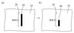
図5・6に、本発明の実施形態2−2を示す。本実施形態2−2では、図5(a)に示すように、ハードコート層11内に棒状のマーカー24を膜厚方向に対して斜めに傾斜させて埋設している。ここでのマーカー24も、実施形態2−1と同様にハードコート層11と共に耐候劣化や研磨が進行するよう樹脂製となっている。また、樹脂基材10の表面には、マーカー24の見た目の長さ(ハードコート層11の表面から確認できる長さ)に対応した目盛り30が記されている。(Embodiment 2-2)
5 and 6 show Embodiment 2-2 of the present invention. In the present embodiment 2-2, as shown in FIG. 5A, a bar-shaped
マーカー24は、少なくともハードコート層11の限界膜厚以上の長さを有し、ハードコート層11の底部から斜めに立設するように埋設されている。当該マーカー24は、樹脂基材10上にハードコート層用塗布液を塗装した後にマーカー24を埋設したうえで、ハードコート層11を硬化させればよい。本実施形態では、マーカー24の初期長さをハードコート層11の初期膜厚において底面から表面に至る長さとしている。 The
そのうえで、ハードコート層11が減膜していなければマーカー24は十分な長さを有し、図6(a)に示すように、マーカー24の見た目の長さも長い。しかし、耐候劣化や傷消し研磨等によってハードコート層11の減膜が進行すると、図5(b)に示すように、マーカー24も同時に短くなっていく。すると、図6(b)に示すように、ハードコート層11の表面から確認できるマーカー24の見た目の長さも徐々に短くなっていく。このとき、マーカー24の見た目の長さは目盛り30によって確認することができる。なお、ハードコート層11が限界膜厚となった時点でのマーカー24の(見た目の)基準長さを予め把握しておく。そして、マーカー24の見た目の長さが基準長さと同等となったところで、ハードコート層11が限界膜厚にまで減膜していると判断することができる。これにより、ハードコート層11をリコートする必要性や傷消し研磨の終了タイミングを把握することができる。 In addition, if the
(実施形態2−2の変形例)
なお、樹脂基材10に記す目盛りは、棒状マーカー24の見た目の長さを数値で表すほか、図7に示すように、単にハードコート層11が限界膜厚にまで減膜されたことを示す基準長さ位置に印を示すだけでもよい。また、目盛りは必ずしも必要なく、棒状マーカー24の見た目の長さをノギス等によって直接測定することもできる。(Modification of Embodiment 2-2)
Note that the scale marked on the
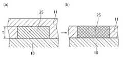
(実施形態3)
図8に、本発明の実施形態3を示す。本実施形態3では、図8(a)に示すように、ハードコート層11の限界膜厚tとほぼ同じ厚みのマーカー25を、ハードコート層11の底部に埋設している。この場合、樹脂基材10上に予めマーカー25を載置ないし貼着したうえで、ハードコート層11を形成するだけでよい。(Embodiment 3)
FIG. 8 shows a third embodiment of the present invention. In the third embodiment, as shown in FIG. 8A, a
ここでのマーカー25は、所定の厚みに形成するベース材料と共に、水分又は酸素と反応して変色する変色成分を有する。ベース材料としては、樹脂、金属、木材、セラミックスなどを特に制限無く使用できる。ベース材料が樹脂であれば、当該ベース材料に変色成分を混合配合することができる。他の材料であれば、所定の厚みに形成したマーカー25の表面に変色成分を塗布すればよい。 The
水分と反応して変色する変色成分としては、塩化コバルトなどが挙げられる。また、酸素と反応して変色する変色成分としては、ポリフェノール類、メチレンブルー、インジゴカーミン、銅,銀等の金属類などが挙げられる。これらの変色成分は、一種のみを単独配合してもよいし、二種以上を混合して配合することもできる。中でも、水分によって変色する変色成分と酸素によって変色する変色成分とを混用することが好ましい。 Examples of the color changing component that changes color by reacting with moisture include cobalt chloride. Examples of the color changing component that changes color by reacting with oxygen include polyphenols, methylene blue, indigo carmine, metals such as copper and silver, and the like. These discoloration components may be blended alone or in a combination of two or more. Among them, it is preferable to mix a color changing component that changes color with moisture and a color changing component that changes color with oxygen.
そのうえで、ハードコート層11が耐候劣化や傷消し研磨等によって減膜しても、マーカー25が変色していない範囲であれば特に問題ない。すなわち、ハードコート層11が限界膜厚tにまで減膜していなければ、マーカー25は初期色のままである。しかし、さらに減膜が進行してハードコート層11が限界膜厚tとなると、マーカー25が外部に露呈される。すると、変色成分が水分や酸素と反応することで、図8(b)に示すように、マーカー25が変色する。これにより、ハードコート層11が限界膜厚tにまで減膜していると判断することができ、ハードコート層11をリコートする必要性や傷消し研磨の終了タイミングを把握することができる。 In addition, even if the
10 樹脂基材
11 ハードコート層
20・22・23・24・25 マーカー
30・31 目盛り
t ハードコート層の限界膜厚
W マーカーの直径
10
Claims (9)
Translated fromJapanese前記ハードコート層内に、前記ハードコート層の限界膜厚の判断基準となるマーカーを有し、
前記ハードコート層が前記限界膜厚にまで減膜すると、前記マーカーの少なくとも一部が消失することを特徴とする、ハードコート層の限界膜厚判断構造。It is a limit film thickness judgment structure of a transparent hard coat layer formed on a resin base material,
The hard coat layer,have a marker of criterion limit the thickness of the hard coatlayer,
When the hard coat layer is reduced to the limit film thickness, at least a part of the marker disappears , the limit film thickness judgment structure of the hard coat layer.
前記ハードコート層内に、前記ハードコート層の限界膜厚の判断基準となるマーカーを有し、
前記マーカーは、水分又は酸素と反応して変色する変色成分を有し、前記ハードコート層の前記限界膜厚となる位置に埋設されている、ハードコート層の限界膜厚判断構造。
It is a limit film thickness judgment structure of a transparent hard coat layer formed on a resin base material,
In the hard coat layer, having a marker that is a criterion for determining the limit film thickness of the hard coat layer,
The marker, moisture or oxygen and has a reaction to discoloring component which changes color, the are embedded in the limit thickness and a position of the hard coatlayer, a limit thickness determined structureHa Dokoto layer.
Priority Applications (1)
| Application Number | Priority Date | Filing Date | Title |
|---|---|---|---|
| JP2012189895AJP5870880B2 (en) | 2012-08-30 | 2012-08-30 | Structure for determining the thickness of the hard coat layer |
Applications Claiming Priority (1)
| Application Number | Priority Date | Filing Date | Title |
|---|---|---|---|
| JP2012189895AJP5870880B2 (en) | 2012-08-30 | 2012-08-30 | Structure for determining the thickness of the hard coat layer |
Publications (2)
| Publication Number | Publication Date |
|---|---|
| JP2014046507A JP2014046507A (en) | 2014-03-17 |
| JP5870880B2true JP5870880B2 (en) | 2016-03-01 |
Family
ID=50606679
Family Applications (1)
| Application Number | Title | Priority Date | Filing Date |
|---|---|---|---|
| JP2012189895AExpired - Fee RelatedJP5870880B2 (en) | 2012-08-30 | 2012-08-30 | Structure for determining the thickness of the hard coat layer |
Country Status (1)
| Country | Link |
|---|---|
| JP (1) | JP5870880B2 (en) |
Families Citing this family (1)
| Publication number | Priority date | Publication date | Assignee | Title |
|---|---|---|---|---|
| US10061058B2 (en)* | 2014-05-21 | 2018-08-28 | Universal City Studios Llc | Tracking system and method for use in surveying amusement park equipment |
Family Cites Families (1)
| Publication number | Priority date | Publication date | Assignee | Title |
|---|---|---|---|---|
| JP5607961B2 (en)* | 2010-03-19 | 2014-10-15 | トヨタホーム株式会社 | Building materials |
- 2012
- 2012-08-30JPJP2012189895Apatent/JP5870880B2/ennot_activeExpired - Fee Related
Also Published As
| Publication number | Publication date |
|---|---|
| JP2014046507A (en) | 2014-03-17 |
Similar Documents
| Publication | Publication Date | Title |
|---|---|---|
| JP4930657B2 (en) | Water repellent film and automotive parts provided with the same | |
| JP2012529079A5 (en) | ||
| KR101975867B1 (en) | Window for display device and display device including the window | |
| KR20160146888A (en) | Optical member, production method therefor, window material, and fixture | |
| WO2014021377A1 (en) | Antireflective article, image display device, and production mold for antireflective article | |
| KR102255973B1 (en) | Retroreflective sheeting including a low-elastic modulus layer | |
| JP6052641B2 (en) | Antifouling film and automobile parts using the same | |
| CN106646705A (en) | Surface layer of reflective film, surface protecting film, reflective film and manufacturing technique thereof | |
| WO2010051432A3 (en) | Retroreflective coating and method for applying a retroreflective coating on a structure | |
| ES2213502T1 (en) | PROCEDURE FOR MARKING OBJECTS OF AN INFALSIFYABLE FORM AND INFALSIFICABLE MARKING. | |
| TW201441649A (en) | Window for display device and display device including the window | |
| JP6890012B2 (en) | Retroreflective sheet material with a substantially amorphous polymer layer | |
| US20170209308A1 (en) | Transparent laminate | |
| JP5870880B2 (en) | Structure for determining the thickness of the hard coat layer | |
| JP2015525131A5 (en) | ||
| JP2018533397A5 (en) | ||
| KR20140121176A (en) | Window for display device and display device including the window | |
| KR20150015906A (en) | LCD Protection Film for Protecting Display | |
| JP2018060134A (en) | Displacement visualization sensor | |
| CN211111730U (en) | Transparent antifogging structure with extensive suitability | |
| CN207216062U (en) | A kind of fabric with reflectance coating | |
| CN110845891A (en) | Preparation method of reflective spray | |
| CN205705527U (en) | A kind of new vehicle reflective membrane | |
| JP5685087B2 (en) | Blindfold film | |
| JP3160844U (en) | Retroreflective member |
Legal Events
| Date | Code | Title | Description |
|---|---|---|---|
| A621 | Written request for application examination | Free format text:JAPANESE INTERMEDIATE CODE: A621 Effective date:20141211 | |
| A977 | Report on retrieval | Free format text:JAPANESE INTERMEDIATE CODE: A971007 Effective date:20150925 | |
| A131 | Notification of reasons for refusal | Free format text:JAPANESE INTERMEDIATE CODE: A131 Effective date:20150929 | |
| A521 | Request for written amendment filed | Free format text:JAPANESE INTERMEDIATE CODE: A523 Effective date:20151127 | |
| TRDD | Decision of grant or rejection written | ||
| A01 | Written decision to grant a patent or to grant a registration (utility model) | Free format text:JAPANESE INTERMEDIATE CODE: A01 Effective date:20151215 | |
| A61 | First payment of annual fees (during grant procedure) | Free format text:JAPANESE INTERMEDIATE CODE: A61 Effective date:20151228 | |
| R151 | Written notification of patent or utility model registration | Ref document number:5870880 Country of ref document:JP Free format text:JAPANESE INTERMEDIATE CODE: R151 | |
| LAPS | Cancellation because of no payment of annual fees |