Movatterモバイル変換


[0]ホーム

URL:


JP5867152B2 - Method for manufacturing absorbent article - Google Patents

Method for manufacturing absorbent article
Download PDF

Info

Publication number
JP5867152B2
JP5867152B2JP2012036110AJP2012036110AJP5867152B2JP 5867152 B2JP5867152 B2JP 5867152B2JP 2012036110 AJP2012036110 AJP 2012036110AJP 2012036110 AJP2012036110 AJP 2012036110AJP 5867152 B2JP5867152 B2JP 5867152B2
Authority
JP
Japan
Prior art keywords
sheet
top sheet
core wrap
joining
absorbent
Prior art date
Legal status (The legal status is an assumption and is not a legal conclusion. Google has not performed a legal analysis and makes no representation as to the accuracy of the status listed.)
Expired - Fee Related
Application number
JP2012036110A
Other languages
Japanese (ja)
Other versions
JP2013169388A (en
Inventor
守 越智
守 越智
Current Assignee (The listed assignees may be inaccurate. Google has not performed a legal analysis and makes no representation or warranty as to the accuracy of the list.)
New Oji Paper Co Ltd
Oji Holdings Corp
Original Assignee
Oji Holdings Corp
Oji Paper Co Ltd
Priority date (The priority date is an assumption and is not a legal conclusion. Google has not performed a legal analysis and makes no representation as to the accuracy of the date listed.)
Filing date
Publication date
Application filed by Oji Holdings Corp, Oji Paper Co LtdfiledCriticalOji Holdings Corp
Priority to JP2012036110ApriorityCriticalpatent/JP5867152B2/en
Publication of JP2013169388ApublicationCriticalpatent/JP2013169388A/en
Application grantedgrantedCritical
Publication of JP5867152B2publicationCriticalpatent/JP5867152B2/en
Expired - Fee Relatedlegal-statusCriticalCurrent
Anticipated expirationlegal-statusCritical

Links

Images

Landscapes

Description

Translated fromJapanese

本発明は,着用者の股下に装着され,尿などの液体を吸収し保持するための吸収性物品及びその製造方法に関する。具体的に説明すると,本発明は,着用者の肌に当接するトップシートに凹凸が形成された吸収性物品及びその製造方法に関するものである。  The present invention relates to an absorbent article that is attached to a crotch of a wearer and absorbs and holds a liquid such as urine and a method for manufacturing the same. If it demonstrates concretely, this invention relates to the absorbent article by which the unevenness | corrugation was formed in the top sheet which contact | abuts a wearer's skin, and its manufacturing method.

従来から,例えば,使い捨ておむつや,生理用ナプキン,失禁パッドのような吸収性物品が知られている。吸収性物品は,一般的に,トップシートと,バックシートと,これらのシート間に介在する吸収体を含む。一般的な吸収性物品において,吸収体は,着用者の肌に接する表面側から液透過性材料で形成されたトップシートにより被覆され,反対の裏面側から液不透過性材料で形成されたバックシートにより被覆されている。このため,着用者が排泄した体液は,トップシートを透過して,吸収体により吸収され,バックシートによって外側への漏出が防止されるようになっている。  Conventionally, for example, absorbent articles such as disposable diapers, sanitary napkins, and incontinence pads are known. The absorbent article generally includes a top sheet, a back sheet, and an absorbent body interposed between these sheets. In a general absorbent article, the absorbent body is covered with a top sheet formed of a liquid permeable material from the surface side that comes into contact with the wearer's skin, and is formed of a liquid impermeable material from the opposite back side. Covered by a sheet. For this reason, the bodily fluid excreted by the wearer passes through the top sheet, is absorbed by the absorbent body, and is prevented from leaking outward by the back sheet.

このような構成を有する吸収性物品は,着用時において,トップシートが着用者の肌に当接する。一般的なトップシートは,不織布や,不織布を二次加工して小孔を形成したものが用いられており,繊維間に液体を引きこむことができる液吸収性で形成されている。ただし,トップシートに引きこまれた液体の多くは,トップシートを透過してその下層に位置する吸収体によって吸収保持されるものの,多少の残液がトップシートには残る。このため,液を吸収したトップシートに着用者の肌が当たると,着用者に対しベタつき感や不快感を与えることがあった。また,湿潤したトップシートに皮膚が長時間触れていると,トップシートと皮膚との摩擦刺激や,尿に含まれる刺激物質によって,皮膚トラブルを招く恐れがあった。  When the absorbent article having such a configuration is worn, the top sheet comes into contact with the wearer's skin. A general top sheet is a non-woven fabric or a non-woven fabric formed by secondary processing of a non-woven fabric to form a small hole, and is formed with a liquid absorbability that can draw liquid between fibers. However, most of the liquid drawn into the top sheet passes through the top sheet and is absorbed and held by the absorber located in the lower layer, but some residual liquid remains in the top sheet. For this reason, when a wearer's skin hits the top sheet which absorbed the liquid, a sticky feeling and a discomfort may be given to the wearer. In addition, when the skin touched the wet topsheet for a long time, there was a risk of causing skin troubles due to frictional stimulation between the topsheet and the skin and irritants contained in the urine.

このため,従来から,トップシートと肌の接触による不快感や皮膚トラブルを解消するための種々の提案がなされている。
例えば,特許文献1には,トップシートに対し熱接着によるエンボス加工を施し,トップシートの構成繊維を部分的に融着させることで,トップシート上に凹凸を形成する技術が開示されている。
また,特許文献2には,トップシートに対し規則的なドット状のエンボス加工を施して,各ドット状のエンボス間を繋ぐライン部分によって凹部を形成し,その他の部分を凸部とする技術が開示されている。
また,特許文献3には,トップシートを,多数の襞寄状部が平行に形成された凹凸形成用シートと,凹凸形成シートを接合するための基材シートとにより構成する技術が開示されている。
また,特許文献4には,トップシートを,潜在捲縮性繊維の層と熱融着性繊維の層とで構成し,潜在捲縮性繊維を加熱してその捲縮性を発現させることにより,トップシートに凹凸を形成するとうい技術が開示されている。
上記従来技術のように,トップシートに凹部と凸部を作り出すことにより,トップシートと着用者の肌の接触面積を低減させることができる。このため,着用者に対しベタつき感や不快感を与えることや,湿潤したトップシートに由来する皮膚トラブルを低減させることができるとされている。
For this reason, conventionally, various proposals have been made to eliminate discomfort and skin troubles due to contact between the top sheet and the skin.
For example,Patent Document 1 discloses a technique for forming irregularities on a top sheet by embossing the top sheet by thermal bonding and partially fusing constituent fibers of the top sheet.
Patent Document 2 discloses a technology in which regular dot-shaped embossing is performed on the top sheet, concave portions are formed by line portions connecting the respective dot-shaped embosses, and other portions are convex portions. It is disclosed.
Patent Document 3 discloses a technique in which a top sheet is constituted by a concavo-convex forming sheet in which a large number of interleaved portions are formed in parallel and a base sheet for bonding the concavo-convex forming sheet. Yes.
InPatent Document 4, the top sheet is composed of a layer of latent crimpable fiber and a layer of heat-fusible fiber, and the latent crimpable fiber is heated to express its crimpability. A technique for forming irregularities on the top sheet is disclosed.
As in the above-described prior art, the contact area between the top sheet and the wearer's skin can be reduced by creating the concave and convex portions on the top sheet. For this reason, it is said that a sticker feeling and a discomfort can be given to the wearer, and skin troubles derived from a wet top sheet can be reduced.

特開2010−148730号公報JP 2010-148730 A特開2008−136563号公報JP 2008-136563 A特開2002−165830号公報JP 2002-165830 A特開2011−208297号公報JP 2011-208297 A

しかしながら,上記特許文献1のように,トップシートに熱接着によるエンボス加工を施す場合,大掛かりな熱エンボス装置を用いることが必要となる。このため,製造装置の導入費用や,メンテナンス費用,人件費などに多くのコストがかかり,結果として吸収性物品の原価が上昇するという問題があった。
また,特許文献2のように,ドット状のエンボス間を繋ぐライン部分によって凹部を形成することで,一時的にはトップシートに凹凸を設けることは可能である。しかし,実際にはトップシートの構成繊維の復元力は高く,トップシートに形成した凹凸を長時間維持することは困難であった。
また,特許文献3のように,トップシートを構成する凹凸形成用シートに多数の襞寄状部を平行に形成する技術は極めて精密な作業が必要である。このため,トップシートの製造工程が複雑になるばかりでなく,その製造に時間を要することから短時間で大量に製造することが困難であった。
さらに,特許文献4のように,トップシートに凹凸を形成するために潜在捲縮性繊維を用いることとすると,トップシートを形成するために,潜在捲縮性繊維層と熱融着性繊維層を重ね合わせる工程や,潜在捲縮性繊維を加熱してその捲縮性を発現させる工程が必要となる。このため,作業工程が長くなり,さらには製造装置が大型化するという問題を有していた。
However, as inPatent Document 1, when embossing is performed on the top sheet by thermal bonding, it is necessary to use a large-scale heat embossing device. For this reason, there is a problem that a lot of costs are added to the manufacturing equipment introduction cost, the maintenance cost, the labor cost, and the cost of the absorbent article increases as a result.
Further, as inPatent Document 2, it is possible to temporarily provide unevenness on the top sheet by forming the concave portion by a line portion connecting the dot-shaped embosses. However, in reality, the restoring force of the constituent fibers of the top sheet is high, and it was difficult to maintain the unevenness formed on the top sheet for a long time.
In addition, as inPatent Document 3, a technique for forming a large number of strut-shaped portions in parallel on the unevenness forming sheet constituting the top sheet requires extremely precise work. For this reason, not only the manufacturing process of the top sheet is complicated, but also it takes time to manufacture the top sheet, so that it is difficult to manufacture the top sheet in a short time.
Furthermore, if the latent crimpable fiber is used to form irregularities on the top sheet as inPatent Document 4, the latent crimpable fiber layer and the heat-fusible fiber layer are formed to form the top sheet. And a process for heating the latent crimpable fiber to develop its crimpability. For this reason, there has been a problem that the work process becomes longer and the manufacturing apparatus becomes larger.

このため,現在は,簡易にトップシートに凹凸を形成して着用者の肌との接触面積を低減させることができ,しかも,トップシートに形成された凹凸を長時間維持することができる吸収性物品,及びその製造方法が求められている。  Therefore, at present, it is possible to reduce the contact area with the wearer's skin by simply forming irregularities on the top sheet, and to maintain the irregularities formed on the top sheet for a long time. There is a need for articles and methods for their manufacture.

そこで,本発明の発明者は,上記の従来発明の問題点を解決する手段について鋭意検討した結果,吸収性物品のトップシートを,その下層に位置する下層シートに部分的に接合してトップシートに凹凸を形成することにより,着用者の肌との接触面積を低減させてベタつき感や肌トラブルを軽減し,かつ,その凹凸を長時間維持することができるという知見を得た。そして,本発明者は,上記知見に基づけば,従来技術の課題を解決できることに想到し,本発明を完成させた。
具体的に本発明は,以下の構成を有する。
Therefore, the inventor of the present invention diligently studied the means for solving the problems of the conventional invention described above, and as a result, the top sheet of the absorbent article was partially joined to the lower layer sheet positioned below the top sheet. It was found that by forming irregularities on the surface, the contact area with the skin of the wearer can be reduced to reduce stickiness and skin trouble, and the irregularities can be maintained for a long time. The inventor has conceived that the problems of the prior art can be solved based on the above knowledge, and has completed the present invention.
Specifically, the present invention has the following configuration.

本発明の第1の側面は,吸収性物品に関する。
本発明の吸収性物品は,着用者の肌に当接する面にトップシート1を備えている。
このトップシート1は,複数の凹部11と複数の凸部12を有している。
複数の凹部11は,トップシート1とトップシート1の下層に位置する下層シートとが接合された接合領域13において,トップシート1の厚みが相対的に小さくなることにより形成されたものである。
一方,複数の凸部12は,トップシート1と下層シートとの非接合領域14において,トップシート1の厚みが相対的に大きくなることにより形成されたものである。
The first aspect of the present invention relates to an absorbent article.
The absorbent article of the present invention includes atop sheet 1 on the surface that comes into contact with the wearer's skin.
Thetop sheet 1 has a plurality ofconcave portions 11 and a plurality ofconvex portions 12.
The plurality ofconcave portions 11 are formed by relatively reducing the thickness of thetop sheet 1 in the joiningregion 13 where thetop sheet 1 and the lower layer sheet positioned below thetop sheet 1 are joined.
On the other hand, the plurality ofconvex portions 12 are formed by relatively increasing the thickness of thetop sheet 1 in thenon-joining region 14 between thetop sheet 1 and the lower layer sheet.

上記構成のように,トップシート1と,トップシート1とは別体に形成された下層シートを,例えばホットメルトのような接合剤を用いて部分的に接合することにより,簡易にトップシート1に凹凸を形成することができる。すなわち,例えば,トップシート1と下層シートの間に部分的に,流動性を有する接合剤を塗工することにより,この接合剤が,トップシート1と下層シートに浸透して,両シートを接合する。すると,接合剤が塗工された接合領域13において,トップシート1は下層シートに接着されて,トップシート1の繊維密度が高まるため,トップシート1の厚みが相対的に小さくなる。他方,接合剤が塗工されていない非接合領域14においては,トップシート1の繊維密度は変化せず,その厚みがそのまま維持されるため,トップシート1の厚みは相対的に大きくなる。このように,トップシート1と下層シートを接合し,接合領域13と非接合領域14において,トップシート1の厚みを変化させることにより,トップシート1に凹部11と凸部12を簡単に形成することが可能である。
また,トップシート1と下層シートを接合してトップシート1に凹凸を付与することにより,トップシート1の凹凸を持続性の高いものとすることができる。
なお,下層シートとは,トップシート1と別体として形成されたシートであり,例えば吸収性コアを被包するコアラップシートであってもよいし,トップシート1に接合するため用途として別途設けられたシートであってもよい。
As described above, thetop sheet 1 and the lower sheet formed separately from thetop sheet 1 are partially bonded using, for example, a bonding agent such as hot melt, so that thetop sheet 1 can be easily obtained. Unevenness can be formed on the surface. That is, for example, by partially applying a fluid bonding agent between thetop sheet 1 and the lower layer sheet, the bonding agent penetrates into thetop sheet 1 and the lower layer sheet and bonds both sheets. To do. Then, in thebonding region 13 where the bonding agent is applied, thetop sheet 1 is bonded to the lower layer sheet, and the fiber density of thetop sheet 1 is increased. Therefore, the thickness of thetop sheet 1 is relatively decreased. On the other hand, in thenon-bonding region 14 where the bonding agent is not applied, the fiber density of thetop sheet 1 does not change and the thickness is maintained as it is, so that the thickness of thetop sheet 1 becomes relatively large. As described above, thetop sheet 1 and the lower layer sheet are joined, and the thickness of thetop sheet 1 is changed in the joiningregion 13 and thenon-joining region 14 to easily form theconcave portion 11 and theconvex portion 12 in thetop sheet 1. It is possible.
Moreover, the unevenness | corrugation of thetop sheet 1 can be made highly sustainable by joining thetop sheet 1 and a lower layer sheet | seat, and providing an unevenness | corrugation to thetop sheet 1. FIG.
The lower layer sheet is a sheet formed separately from thetop sheet 1, and may be, for example, a core wrap sheet that encloses the absorbent core, or provided separately as a use for joining thetop sheet 1. It may be a sheet obtained.

本発明のある実施形態に係る吸収性物品は,トップシート1と,バックシート2と,トップシート1とバックシート2の間に介在された吸収体3を有する。また,吸収体3は,トップシート1側に位置する上側コアラップシート31と,バックシート2側に位置する下側コアラップシート32と,上側コアラップシート31と下側コアラップシート32により封入された吸収性コア33を有している。
この場合において,上記した下層シートは,吸収体3の上側コアラップシート31であることが好ましい。
すなわち,トップシート1に形成された複数の凹部11は,トップシート1と上側コアラップシート31を接合した接合領域13に形成されたものであり,他方,複数の凸部12は,トップシート1と上側コアラップシート31の非接合領域14に形成されたものであることが好ましい。
An absorbent article according to an embodiment of the present invention includes atop sheet 1, aback sheet 2, and anabsorbent body 3 interposed between thetop sheet 1 and theback sheet 2. Theabsorber 3 is enclosed by the uppercore wrap sheet 31 located on thetop sheet 1 side, the lowercore wrap sheet 32 located on theback sheet 2 side, and the uppercore wrap sheet 31 and the lowercore wrap sheet 32. Theabsorbent core 33 is provided.
In this case, the lower layer sheet is preferably the uppercore wrap sheet 31 of theabsorbent body 3.
That is, the plurality ofconcave portions 11 formed in thetop sheet 1 are formed in the joiningregion 13 where thetop sheet 1 and the uppercore wrap sheet 31 are joined, while the plurality ofconvex portions 12 are formed in thetop sheet 1. It is preferably formed in the non-bondedregion 14 of the uppercore wrap sheet 31.

上記構成のように,トップシート1と上側コアラップシート31を接合することによっても,トップシート1に凹凸を付与することができる。また,トップシート1と上側コアラップシート31の間に流動性を有する接合剤を部分的に塗工して,両者を接合することで,トップシート1と吸収体3の間の距離を近づけることができる。このため,尿などの液体がトップシート1を透過した後,迅速に吸収体3によって吸収されるようになり,トップシート1に残液が残りにくくなる。従って,上記構成によれば,トップシート1に凹凸を付与したことと,トップシート1を吸収体3に近接させたことが相俟って,着用者に対しベタつき感や不快感を与えにくくなり,肌トラブルも低減できるため,おむつの装着感が良好なものとなる。  Concavity and convexity can be imparted to thetop sheet 1 by joining thetop sheet 1 and the uppercore wrap sheet 31 as in the above configuration. Moreover, the adhesive agent which has fluidity | liquidity is partially coated between thetop sheet 1 and the upper core wrap sheet |seat 31, and the distance between thetop sheet 1 and theabsorber 3 is made close by joining both. Can do. For this reason, after a liquid such as urine has permeated through thetop sheet 1, the liquid is quickly absorbed by theabsorber 3, and the remaining liquid is hardly left on thetop sheet 1. Therefore, according to the above configuration, it is difficult to give the wearer a feeling of stickiness or discomfort due to the fact that thetop sheet 1 is uneven and thetop sheet 1 is close to theabsorbent body 3. Because skin troubles can be reduced, the diaper feels good.

本発明の吸収性物品において,接合領域13は,線状であり,トップシート1の長手方向に延びて,複数本形成されていることとしてもよい。また,線状の接合領域13は,それぞれトップシート1の短手方向に間隔を空けて設けられていることが好ましい。  In the absorbent article of the present invention, the joiningregion 13 may be linear, and a plurality of joiningregions 13 may be formed extending in the longitudinal direction of thetopsheet 1. Moreover, it is preferable that the linear joining area |region 13 is provided at intervals in the transversal direction of thetop sheet 1, respectively.

上記構成のように,接合領域13をトップシート1の長手方向に延びる線状とし,各接合領域13間に間隔を設けることにより,トップシート1の凹部11(接合領域13)に沿わせて,尿などの液体を吸収体3の長手方向に拡散させることができる。通常,吸収体3が尿を吸収する際の吸収部分は1箇所に集中しやすいが,吸収部分を吸収体3の長手方向に拡散させることで,より効率的に液体を吸収保持することが可能になる。  Like the above configuration, the joiningregion 13 is formed in a linear shape extending in the longitudinal direction of thetop sheet 1, and by providing an interval between each joiningregion 13, along the concave portion 11 (joining region 13) of thetop sheet 1, Liquid such as urine can be diffused in the longitudinal direction of theabsorber 3. Normally, the absorption part when theabsorber 3 absorbs urine is likely to concentrate in one place, but by absorbing the absorption part in the longitudinal direction of theabsorber 3, the liquid can be absorbed and held more efficiently. become.

本発明の吸収性物品において,接合領域13は,複数のS字状が連続した形状であり,トップシート1の長手方向に延びて,複数本形成されていることとしてもよい。また,複数のS字状が連続した形状の接合領域13は,それぞれトップシート1の短手方向に間隔を空けて設けられていることが好ましい。  In the absorbent article of the present invention, the joiningregion 13 may have a shape in which a plurality of S-shapes are continuous, and a plurality of joiningregions 13 may be formed extending in the longitudinal direction of thetopsheet 1. Moreover, it is preferable that the joining area |region 13 of the shape where several S-shape continued was provided at intervals in the transversal direction of thetop sheet 1, respectively.

上記構成のように,接合領域13を複数のS字状が連続した形状とすることにより,トップシート1の長手方向と短手方向にそれぞれに凹凸を形成でき,凹凸の連続が細かくなる。また,S字の湾曲部分には特にトップシート1と下層シートの間に空隙が生じ易く,トップシート1の凸部12が比較的大きく膨らむ。このため,接合領域13をS字状に形成することで,トップシート1のクッション性を高めることができる。  As described above, by forming the joiningregion 13 in a shape in which a plurality of S-shapes are continuous, unevenness can be formed in the longitudinal direction and the short-side direction of thetop sheet 1, and the continuity of the unevenness becomes fine. Further, in the S-shaped curved portion, a gap is easily generated particularly between thetop sheet 1 and the lower layer sheet, and theconvex portion 12 of thetop sheet 1 swells relatively large. For this reason, the cushioning property of thetop sheet 1 can be improved by forming the joiningregion 13 in an S shape.

本発明の第2の側面は,着用者の肌に当接する面にトップシート1を備えた吸収性物品の製造方法に関する。
この製造方法では,
トップシート1の下層に位置する下層シート上に,部分的に接合剤を塗布する工程と,
接合剤により,トップシート1と下層シートを部分的に接合する工程を行う。
そして,トップシート1と下層シートの接合領域13において,トップシート1の厚みを相対的に小さくすることによりトップシート1に凹部11を形成し,トップシート1と下層シートの非接合領域14において,トップシート1の厚みを相対的に大きくすることによりトップシート1に凸部12を形成する。
The 2nd side surface of this invention is related with the manufacturing method of the absorbent article which provided thetop sheet 1 in the surface contact | abutted to a wearer's skin.
In this manufacturing method,
A step of partially applying a bonding agent on a lower layer sheet located below thetop sheet 1;
A step of partially bonding thetop sheet 1 and the lower layer sheet with the bonding agent is performed.
And in the joining area |region 13 of thetop sheet 1 and a lower layer sheet, the recessedpart 11 is formed in thetop sheet 1 by making the thickness of thetop sheet 1 relatively small, and in the non-joining area |region 14 of thetop sheet 1 and a lower layer sheet, Theconvex portion 12 is formed on thetop sheet 1 by relatively increasing the thickness of thetop sheet 1.

本発明の第2の側面に係る製造方法によれば,上記第1の側面に係る吸収性物品を製造することができる。  According to the manufacturing method according to the second aspect of the present invention, the absorbent article according to the first aspect can be manufactured.

本発明の製造方法では,トップシート1を下層シートに接合する前に,トップシート1又は下層シートを延伸させる工程を行うことが好ましい。  In the manufacturing method of this invention, it is preferable to perform the process of extending thetop sheet 1 or a lower layer sheet, before joining thetop sheet 1 to a lower layer sheet.

上記工程のように,トップシート1を下層シートに接合する前に,トップシート1又は下層シートを,その長手方向及び短手方向,又はそのいずれか一方の方向に延伸させることにより,トップシート1を下層シートに接合した後,延伸されたシートが収縮するため,接合領域13と非接合領域14において,トップシート1に厚みに,差が生じやすくなる。このため,トップシート1により顕著な凹凸を形成することができる。  Like the said process, before joining thetop sheet 1 to a lower layer sheet, thetop sheet 1 or a lower layer sheet is extended | stretched in the longitudinal direction and a transversal direction, or any one direction, Thetop sheet 1 Since the stretched sheet contracts after bonding the sheet to the lower layer sheet, a difference in the thickness of thetop sheet 1 tends to occur between thebonding region 13 and thenon-bonding region 14. For this reason, a remarkable unevenness | corrugation can be formed with thetop sheet 1. FIG.

本発明のある実施形態に係る製造方法は,トップシート1と,バックシート2と,トップシート1とバックシート2の間に介在された吸収体3を有し,吸収体3は,トップシート1側に位置する上側コアラップシート31と,バックシート2側に位置する下側コアラップシート32と,上側コアラップシート31と下側コアラップシート32により封入された吸収性コア33を有する吸収性物品を製造する方法である。
この製造方法は,まず,
バックシート2上に下側コアラップシート32が配設され,下側コアラップシート32上に吸収性コア33が配設された物品を得る工程と,
トップシート1と上側コアラップシート31を部分的に接合し,接合領域13において相対的に厚みが小さくなることにより凹部11が形成され,非接合領域14において相対的に厚み大きくなることにより凸部12が形成されたトップシート1と,上側コアラップシート31との接合体を得る工程と,を行う。
そして,その後,トップシート1と上側コアラップシート31の接合体を平面側から押圧して圧着させる工程を行う。
そして,上記物品上に,上記接合体を接合する工程を行う。
The manufacturing method according to an embodiment of the present invention includes atop sheet 1, aback sheet 2, and anabsorbent body 3 interposed between thetop sheet 1 and theback sheet 2. The uppercore wrap sheet 31 located on the side, the lowercore wrap sheet 32 located on theback sheet 2 side, and theabsorbent core 33 enclosed by the uppercore wrap sheet 31 and the lower core wrap sheet 32 A method for manufacturing an article.
This manufacturing method starts with
Obtaining an article in which a lowercore wrap sheet 32 is disposed on theback sheet 2 and anabsorbent core 33 is disposed on the lowercore wrap sheet 32;
Thetop sheet 1 and the uppercore wrap sheet 31 are partially joined, and theconcave portion 11 is formed by a relatively small thickness in thejoint region 13, and the convex portion by a relatively large thickness in thenon-joined region 14. The process of obtaining the joined body of thetop sheet 1 in which 12 is formed and the uppercore wrap sheet 31 is performed.
And after that, the process of pressing and pressing the joined body of thetop sheet 1 and the uppercore wrap sheet 31 from the plane side is performed.
And the process of joining the said conjugate | zygote on the said article | item is performed.

例えば,上側コアラップシート31と下側コアラップシート32により吸収性コア33を被包した後,トップシート1を上側コアラップシート31に接合すると,トップシート1と上側コアラップシート31を圧着させにくく,両者の接合状態を十分なものとすることは困難である。この点,本発明の工程のように,トップシート1と上側コアラップシート31の接合体を,バックシート2,下側コアラップシート32,及び吸収性コア33により構成される物品に取り付ける前に,当該接合体を平面側から押圧して圧着しておくことにより,トップシート1と上側コアラップシート31に対し十分に圧力を与えることができる。これにより,トップシート1と上側コアラップシート31の接合状態を良好なものとすることができる。さらに,トップシート1と上側コアラップシート31の接合状態が良好になれば,接合領域13と非接合領域14において,トップシート1に厚みの差が生じやすくなる。このため,トップシート1に,より顕著な凹凸を発現させることができるようになる。  For example, after theabsorbent core 33 is encapsulated by the uppercore wrap sheet 31 and the lowercore wrap sheet 32, when thetop sheet 1 is joined to the uppercore wrap sheet 31, thetop sheet 1 and the uppercore wrap sheet 31 are pressed together. It is difficult, and it is difficult to make the bonding state between the two satisfactory. In this respect, before attaching the joined body of thetop sheet 1 and the uppercore wrap sheet 31 to the article composed of theback sheet 2, the lowercore wrap sheet 32, and theabsorbent core 33, as in the process of the present invention. By pressing the bonded body from the plane side and pressing it, thetop sheet 1 and the uppercore wrap sheet 31 can be sufficiently pressurized. Thereby, the joining state of thetop sheet 1 and the uppercore wrap sheet 31 can be made favorable. Furthermore, if the joining state of thetop sheet 1 and the uppercore wrap sheet 31 becomes good, a difference in thickness is likely to occur in thetop sheet 1 in the joiningregion 13 and thenon-joining region 14. For this reason, thetop sheet 1 can be made to have more prominent irregularities.

本発明は,トップシートと下層シートを接合するだけで簡易にトップシートに対して凹凸を付与できるため,熱エンボス装置のような大掛かりな装置を使用する必要がなく,製造装置の導入費用等の面において,吸収性物品の製造に掛かる費用を低減させることができる。
また,本発明は,吸収性物品のトップシートを,その下層に位置する下層シートに部分的に接合してトップシートに凹凸を形成するため,着用者の肌との接触面積を低減させてベタつき感や肌トラブルを軽減し,かつ,その凹凸を長時間維持することができる。
また,トップシートと下層シートを接合するだけで簡易にトップシートに対して凹凸を付与できるため,トップシートに凹凸が付与された吸収性物品を短時間で大量に製造することができる。
さらに,本発明は,ホットメルト塗布装置などを用いて,トップシートと下層シートを接合するものであるため,特殊な装置を用いる必要がなく製造装置の大型化することを回避できる。
Since the present invention can easily give irregularities to the top sheet simply by joining the top sheet and the lower layer sheet, it is not necessary to use a large-scale device such as a heat embossing device, and the introduction cost of the manufacturing equipment, etc. In terms of cost, the cost for manufacturing the absorbent article can be reduced.
In addition, the present invention partially adheres the top sheet of the absorbent article to the lower layer sheet located below the absorbent sheet to form irregularities on the top sheet, thereby reducing the contact area with the wearer's skin and stickiness. The feeling and skin troubles can be reduced and the unevenness can be maintained for a long time.
Moreover, since unevenness | corrugation can be easily provided with respect to a top sheet only by joining a top sheet and a lower layer sheet, the absorbent article by which the unevenness | corrugation was provided to the top sheet can be manufactured in large quantities in a short time.
Furthermore, the present invention joins the top sheet and the lower layer sheet using a hot melt coating apparatus or the like, so that it is not necessary to use a special apparatus and an increase in the size of the manufacturing apparatus can be avoided.

図1は,本発明に係る吸収性物品例を示す展開図であり,吸収性物品をトップシート側からみた状態を示している。FIG. 1 is a development view showing an example of an absorbent article according to the present invention, showing a state in which the absorbent article is viewed from the top sheet side.図2は,吸収性物品の断面形状を示している。図2(a)は,図1に示されたX−X´の線分で吸収性物品切断した状態を示す断面図であり,図2(b)は,図2(a)に示された枠B内を拡大して示した拡大断面図である。FIG. 2 shows a cross-sectional shape of the absorbent article. 2A is a cross-sectional view showing a state in which the absorbent article is cut along the line XX ′ shown in FIG. 1, and FIG. 2B is shown in FIG. FIG. 5 is an enlarged cross-sectional view showing the inside of a frame B in an enlarged manner.図3は,トップシートと下層シートの接合パターンの例を示している。FIG. 3 shows an example of the joining pattern of the top sheet and the lower layer sheet.図4は,本発明の他の実施形態に係る吸収性物品の例を示す断面図である。FIG. 4 is a cross-sectional view showing an example of an absorbent article according to another embodiment of the present invention.図5は,本発明に係る吸収性物品の製造方法の例を示す概念図である。FIG. 5 is a conceptual diagram showing an example of a method for manufacturing an absorbent article according to the present invention.

以下,図面を用いて本発明を実施するための形態について説明する。以下では,吸収性物品の例として使い捨ておむつを挙げて説明するが,本発明は,以下に説明する形態に限定されるものではなく,以下の形態から当業者が自明な範囲で適宜修正したものも含む。
例えば,本発明は,使い捨ておむつやだけでなく,生理用ナプキンや,失禁パッドのような公知の吸収性物品に適用可能である。
なお,本願明細書において,使い捨ておむつやトップシートの「長手方向」というときは,使い捨ておむつの前身頃と後身頃を結ぶ方向(図1における上下方向)を意味し,「短手方向」というときは,上記「長手方向」と直交する方向(図1における左右方向)を意味する。
また,本願明細書において,「A〜B」とは,「A以上B以下」であることを意味する。
Hereinafter, embodiments for carrying out the present invention will be described with reference to the drawings. In the following, a disposable diaper will be described as an example of an absorbent article, but the present invention is not limited to the form described below, and is appropriately modified by those skilled in the art from the following form. Including.
For example, the present invention can be applied not only to disposable diapers but also to known absorbent articles such as sanitary napkins and incontinence pads.
In the present specification, the “longitudinal direction” of the disposable diaper and the top sheet means the direction (vertical direction in FIG. 1) connecting the front body and the back body of the disposable diaper, and the “short direction”. Means a direction (left-right direction in FIG. 1) orthogonal to the “longitudinal direction”.
In the present specification, “A to B” means “A or more and B or less”.

(1.使い捨ておむつの全体構成)
本発明は,例えば使い捨ておむつに代表される吸収性物品に関する。例えば,本発明は,パンツ型の使い捨ておむつやテープ型のような公知のタイプの使い捨ておむつに適用することができる。
パンツ型の使い捨ておむつは,前身頃と後身頃の両側部が接合されることにより,胴回りと各脚部周りに開口部が形成されるタイプのおむつである。パンツ型の使い捨ておむつは,胴回りの開口部から両脚を入れ,各脚部周りの開口部から両脚を出すことにより,着用者に装着される。
また,テープ型の使い捨ておむつは,後身頃の両端部に止着テープが設けられているタイプのおむつである。テープ型の使い捨ておむつは,後身頃に取り付けられている止着テープを,着用者の背部側から腹部側に回して,前身頃に取り付けることにより着用者に装着される。
(1. Overall configuration of disposable diapers)
The present invention relates to an absorbent article represented by, for example, a disposable diaper. For example, the present invention can be applied to known types of disposable diapers such as pants-type disposable diapers and tape-types.
The pants-type disposable diaper is a type of diaper in which openings are formed around the waist and each leg by joining both sides of the front body and the back body. A pants-type disposable diaper is worn by the wearer by putting both legs through the opening around the waist and taking out both legs through the opening around each leg.
A tape-type disposable diaper is a diaper in which fastening tapes are provided at both ends of the back body. A tape-type disposable diaper is attached to the wearer by turning the fastening tape attached to the back body from the back side of the wearer to the abdomen side and attaching it to the front body.

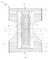
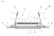
図1は,本発明に係る使い捨ておむつの例を示す展開図であり,使い捨ておむつ100をトップシート1側からみた状態を示している。図2(a)は,図1におけるX−X´の線分において,使い捨ておむつ100を切断した状態の例を示す断面図である。さらに,図2(b)は,図2(b)に示された枠Bを拡大して示した拡大断面図である。  FIG. 1 is a development view showing an example of a disposable diaper according to the present invention, and shows a state in which adisposable diaper 100 is viewed from thetop sheet 1 side. Fig.2 (a) is sectional drawing which shows the example of the state which cut | disconnected thedisposable diaper 100 in the line segment of XX 'in FIG. Further, FIG. 2B is an enlarged sectional view showing the frame B shown in FIG. 2B in an enlarged manner.

図1に示された例において,使い捨ておむつ100は,前身頃外装体41と,後身頃外装体42と,吸収性本体43を有している。前身頃外装体41は,装着時において着用者の腹部に接触し,後身頃外装体42は,装着時において着用者の背部に接触する。吸収性本体43は,その長手方向の一端部側が前身頃外装体41に固定され,他端部側が後身頃外装体42の間に固定される。このため,本発明では,吸収性本体43が,前身頃外装体41と後身頃外装体42との間に架橋された状態となっている。前身頃外装体41と後身頃外装体42の両側縁部を接合することにより,胴回りと各脚部周りに開口部が形成される。これによりパンツ型の使い捨ておむつが形成される。  In the example shown in FIG. 1, thedisposable diaper 100 includes a frontbody exterior body 41, a backbody exterior body 42, and an absorbentmain body 43. The frontbody exterior body 41 contacts the wearer's abdomen when worn, and the backbody exterior body 42 contacts the wearer's back when worn. The absorbentmain body 43 has one end side in the longitudinal direction fixed to the frontbody exterior body 41 and the other end side fixed between the rearbody exterior body 42. For this reason, in this invention, the absorptivemain body 43 is in the state bridge | crosslinked between the frontbody exterior body 41 and the backbody exterior body 42. FIG. By joining both side edges of the frontbody exterior body 41 and the backbody exterior body 42, openings are formed around the trunk and each leg. Thereby, a pants-type disposable diaper is formed.

(1−1.前身頃外装体及び後身頃外装体)
前身頃外装体41及び後身頃外装体42は,着用者の腹部及び背部に接触するとともに,使い捨ておむつ100の着用時において,前身頃外装体41及び後身頃外装体42の間に位置する吸収性本体43を,吊持するための部材である。前身頃外装体41と後身頃外装体42の両側縁部は,互いに重ね合わされ,例えば,熱エンボス加工やソニック溶着のような公知の接合手段により接合される。
(1-1. Front body exterior body and back body exterior body)
The frontbody exterior body 41 and the backbody exterior body 42 are in contact with the wearer's abdomen and back, and absorbable between the frontbody exterior body 41 and the backbody exterior body 42 when thedisposable diaper 100 is worn. It is a member for suspending themain body 43. Both side edges of the frontbody exterior body 41 and the backbody exterior body 42 are overlapped with each other and joined by a known joining means such as hot embossing or sonic welding.

前身頃外装体41及び後身頃外装体42は,例えばインナーシートとアウターシートを重ね合わせることにより構成されている。インナーシートは,着用者の肌に接する面(肌当接面)側に配置され,アウターシートは,着用者の肌に接しない面(肌非当接面)側に配置される。インナーシートとアウターシートは,別途形成されたシート材であってもよいし,例えば一枚のシート材を使い捨ておむつの腰周り開口部の端縁に相当する位置で折り返すことにより一体的に形成されたものであってもよい。インナーシートとアウターシートは,例えば,柔軟な繊維不織布やプラスチックシートや,それらのラミネートシートによって形成されている。インナーシートとアウターシートの間は,例えばホットメルト接着剤によって接着される。  The frontbody exterior body 41 and the backbody exterior body 42 are configured, for example, by overlapping an inner sheet and an outer sheet. The inner sheet is disposed on the surface (skin contact surface) side that contacts the wearer's skin, and the outer sheet is disposed on the surface (skin non-contact surface) side that does not contact the wearer's skin. The inner sheet and the outer sheet may be separately formed sheet materials, for example, formed integrally by folding one sheet material at a position corresponding to the edge of the waist opening of the disposable diaper. It may be. The inner sheet and the outer sheet are formed of, for example, a flexible fiber nonwoven fabric, a plastic sheet, or a laminate sheet thereof. The inner sheet and the outer sheet are bonded by, for example, a hot melt adhesive.

また,インナーシートとアウターシートの間には,使い捨ておむつの幅方向に沿って,複数のタミー伸縮部材51や,複数のウエスト伸縮部材52が,伸長状態で固定されている。
タミー伸縮部材51は,前身頃外装体41及び後身頃外装体42の幅方向にわたって伸長状態で配置されており,収縮することにより,使い捨ておむつの腹周りにタミーギャザーを形成するための部材である。複数のタミー伸縮部材51のそれぞれは,実質的に平行に配置されることが好ましい。
ウエスト伸縮部材52は,前身頃外装体41及び後身頃外装体42の腰周り開口部の端縁に沿って配置され,収縮することにより,使い捨ておむつの腰周り開口部近傍に,ウエストギャザーを形成するための部材である。複数のウエスト伸縮部材52は,インナーシートとアウターシートの間に伸長状態で固定されている。複数のウエスト伸縮部材52は,図2に示されるように,使い捨ておむつの長手方向に所定間隔で,略平行に並置されることが好ましい。
Further, between the inner sheet and the outer sheet, a plurality of tammyelastic members 51 and a plurality of waistelastic members 52 are fixed in an extended state along the width direction of the disposable diaper.
The tammystretchable member 51 is arranged in a stretched state over the width direction of the frontbody exterior body 41 and the backbody exterior body 42, and is a member for forming a tammy gather around the stomach of the disposable diaper by contracting. . Each of the plurality of Tammyelastic members 51 is preferably arranged substantially in parallel.
The waistelastic member 52 is disposed along the edge of the waist opening of the frontbody exterior body 41 and the backbody exterior body 42 and contracts to form a waist gather near the waist opening of the disposable diaper. It is a member for doing. The plurality of waistelastic members 52 are fixed in an extended state between the inner sheet and the outer sheet. As shown in FIG. 2, the plurality of waistelastic members 52 are preferably juxtaposed in parallel in the longitudinal direction of the disposable diaper at predetermined intervals.

(1−2.吸収性本体)
吸収性本体43は,前身頃外装体41と後身頃外装体42の間に架橋された状態で保持され,使い捨ておむつ100の着用時おいて,着用者の股下に位置し,着用者が排泄した尿などの液体を吸収保持するための部材である。図2(a)の断面図に示されるように,吸収性本体43は,トップシート1と,バックシート2と,吸収体3と,サイドシート4と,立体ギャザー伸縮部材5と,カバーシート6を基本構成としている。
(1-2. Absorbent body)
The absorbentmain body 43 is held in a state of being bridged between the frontbody exterior body 41 and the backbody exterior body 42, and is located in the inseam of the wearer when thedisposable diaper 100 is worn, and the wearer excretes it. It is a member for absorbing and holding liquid such as urine. 2A, the absorbentmain body 43 includes atop sheet 1, aback sheet 2, anabsorbent body 3, aside sheet 4, a three-dimensional gatherelastic member 5, and acover sheet 6. Is the basic configuration.

(1−2−1.吸収体)
まず,吸収体3の構成について説明する。吸収体3は,尿などの液体を吸収し,吸収した液体を保持するための部材である。吸収体3は,液透過性のトップシート1と,液不透過性のバックシート2の間に配置される。
(1-2-1. Absorber)
First, the configuration of theabsorber 3 will be described. Theabsorber 3 is a member for absorbing liquid such as urine and holding the absorbed liquid. Theabsorber 3 is disposed between the liquid-permeabletop sheet 1 and the liquid-impermeable back sheet 2.

吸収体3は,図2に示されるように,吸収性材料を単層又は複数層のマット状に形成された吸収性コア33と,吸収性コア33を肌当接面側から被覆する上側コアラップシート31と,吸収性コア33を下側から被覆する下側コアラップシート32により構成されている。吸収性コア33は,上側コアラップシート31と下側コアラップシート32により吸収性材料が外側へ漏れ出さないように周囲を被包されている。  As shown in FIG. 2, theabsorbent body 3 includes anabsorbent core 33 in which an absorbent material is formed in a single-layer or multiple-layer mat, and an upper core that covers theabsorbent core 33 from the skin contact surface side. Thewrap sheet 31 and the lowercore wrap sheet 32 that covers theabsorbent core 33 from below are configured. Theabsorbent core 33 is surrounded by the uppercore wrap sheet 31 and the lowercore wrap sheet 32 so that the absorbent material does not leak outside.

吸収性コア33は,トップシート1を透過した液体を吸収する機能を有し,吸収性材料により構成される。吸収性材料には,公知の材料を採用することができる。吸収性材料としては,例えば,フラップパルプ,高吸収性ポリマー,又は親水性シートを用いることとしても良い。また,吸収性材料には,フラップパルプ,高吸収性ポリマー,又は親水性シートのうち1種類を単独で用いてもよいし,2種類以上を併用することとしてもよい。吸収性材料は,通常,単層又は複数層のマット状に形成され用いられる。
また,上側コアラップシート31及び下側コアラップシート32は,吸収性物品に公知の材料で形成することができ,例えば,ティッシュペーパーのような不織布があげられる。例えば,不織布は,スパンボンド不織布,SMS不織布,SMMS不織布,エアスルー不織布,及びエアレイド不織布のいずれであってもよい。
Theabsorbent core 33 has a function of absorbing the liquid that has passed through thetop sheet 1 and is made of an absorbent material. A well-known material can be employ | adopted for an absorptive material. As the absorbent material, for example, flap pulp, superabsorbent polymer, or hydrophilic sheet may be used. In addition, as the absorbent material, one kind of flap pulp, superabsorbent polymer, or hydrophilic sheet may be used alone, or two or more kinds may be used in combination. The absorbent material is usually formed and used in the form of a single layer or a plurality of layers.
Further, the uppercore wrap sheet 31 and the lowercore wrap sheet 32 can be formed of a known material for the absorbent article, and examples thereof include a nonwoven fabric such as tissue paper. For example, the nonwoven fabric may be any of a spunbond nonwoven fabric, an SMS nonwoven fabric, an SMMS nonwoven fabric, an air-through nonwoven fabric, and an airlaid nonwoven fabric.

(1−2−2.トップシート)
トップシート1は,着用者の股下部の肌に直接接し,尿などの液体を吸収体3に透過させるための部材である。このため,トップシート1は,柔軟性の高い液透過性材料で構成される。また,トップシート1は,吸収体3の肌当接面側を被覆するように配置される。
(1-2-2. Top sheet)
Thetop sheet 1 is a member that is in direct contact with the skin of the wearer's crotch and allows liquid such as urine to pass through theabsorber 3. For this reason, thetop sheet 1 is composed of a highly flexible liquid-permeable material. Thetop sheet 1 is disposed so as to cover the skin contact surface side of theabsorbent body 3.

トップシート1を構成する不透過性材料の例は,織布,不織布,又は多孔性フィルムである。また,例えばポリプロピレンやポリエチレン,ポリエステル,ナイロンのような熱可塑性樹脂の繊維を親水化処理してさらに不織布にしたものを用いることとしてもよい。  The example of the impermeable material which comprises thetop sheet 1 is a woven fabric, a nonwoven fabric, or a porous film. Further, for example, a fiber made of a thermoplastic resin such as polypropylene, polyethylene, polyester, or nylon, which has been subjected to a hydrophilization treatment and further made into a non-woven fabric may be used.

また,本発明において,トップシート1は,比較的嵩量が高い材料で形成されているものであることが好ましい。例えば,トップシート1は,構成繊維の坪量が35g/m以下であって,荷重2kPaで押圧した際のシート厚さが0.2mm以上であることが好ましい。特に,トップシート1は,坪量が15〜25g/m,荷重2kPa押圧時の厚さが0.25〜0.8mmのシートを用いることが好ましい。このように,トップシート1に,嵩高の不織布シートを用いることにより,トップシート1の下層に位置する下層シートに接合した際,トップシート1の表面上に凹凸が発現し易くなる。また,嵩高の不織布シートとしては,例えば,エアスルー,スパンボンド,カードエンボス,又はスパンレースのような不織布シートを好適に用いることができる。また,不織布シートには,界面活性剤による親水化処理等を施すことが好ましい。In the present invention, thetop sheet 1 is preferably made of a material having a relatively high bulk. For example, thetop sheet 1 preferably has a basis weight of the constituent fibers of 35 g / m2 or less and a sheet thickness of 0.2 mm or more when pressed with a load of 2 kPa. In particular, thetop sheet 1 is preferably a sheet having a basis weight of 15 to 25 g / m2 and a thickness of 0.25 to 0.8 mm when a load of 2 kPa is pressed. Thus, when a bulky nonwoven fabric sheet is used for thetop sheet 1, unevenness is likely to appear on the surface of thetop sheet 1 when bonded to the lower layer sheet positioned below thetop sheet 1. Moreover, as a bulky nonwoven fabric sheet, for example, a nonwoven fabric sheet such as air-through, spunbond, card embossing, or spunlace can be suitably used. The nonwoven fabric sheet is preferably subjected to a hydrophilic treatment with a surfactant.

図2(b)の拡大断面図に示されるように,トップシート1は,着用者の肌に当接しない方向(下方)に窪んだ複数の凹部11と,肌に当接する方向(上方)に突起した凸部12を有する。すなわち,トップシート1は,その下層に位置する吸収体3の上側コアラップシート31に対し,複数の接合領域13において接合されている。接合領域13には,例えばホットメルトのような流動性を有する接合剤が塗布されており,接合領域13において,接合剤がトップシート1と上側コアラップシート31に浸透して,両シートを解離しないように固着する。このため,トップシート1は,上側コアラップシート31との接合領域13において,繊維密度が高まってその厚みが相対的に小さくなるため,トップシート1に凹部11が形成される。ホットメルト接着剤としては,ゴム系,ポリオレフィン系,酢酸ビニル系等の流動性のあるホットメルト接着剤から適宜選択することができ,例えば,SBS(スチレン−ブタジエン−スチレン共重合物),SIS(スチレン−イソブチレン−スチレン共重合物),SEBS(スチレン−エチレン−ブチレン−スチレン共重合物),SEPS(スチレン−エチレン−プロピレン−スチレン共重合物),APAO(Amorphous Poly Alpha Orefin)などをベースポリマーとしたものを使用できる。  As shown in the enlarged cross-sectional view of FIG. 2 (b), thetop sheet 1 has a plurality ofrecesses 11 that are recessed in a direction that does not contact the wearer's skin (downward) and a direction that contacts the skin (upward). It has theconvex part 12 which protruded. That is, thetop sheet 1 is bonded to the uppercore wrap sheet 31 of theabsorbent body 3 located in the lower layer in a plurality ofbonding regions 13. For example, a bonding agent having fluidity such as hot melt is applied to thebonding region 13, and in thebonding region 13, the bonding agent penetrates into thetop sheet 1 and the uppercore wrap sheet 31 to dissociate both sheets. Do not stick. For this reason, since the fiber density increases and the thickness becomes relatively small in the joiningregion 13 with the uppercore wrap sheet 31, thetop sheet 1 is formed with therecess 11 in thetop sheet 1. The hot-melt adhesive can be appropriately selected from fluid hot-melt adhesives such as rubber, polyolefin, and vinyl acetate. For example, SBS (styrene-butadiene-styrene copolymer), SIS ( Base polymers such as styrene-isobutylene-styrene copolymer), SEBS (styrene-ethylene-butylene-styrene copolymer), SEPS (styrene-ethylene-propylene-styrene copolymer), APAO (Amorphous Poly Alpha Orefin), etc. Can be used.

他方,トップシート1の複数の凸部12は,複数の凹部11の間に形成される。すなわち,トップシート1に形成された複数の凸部12は,各接合領域13の間に設けられた非接合領域14において,トップシート1の厚みが相対的に大きくなることにより,トップシート1が部分的に突起したものである。接合領域13と非接合領域14は,例えば所定のパターンで交互に連続するように形成されている。このように,トップシート1と上側コアラップシート31を部分的に接合し,接合領域13と非接合領域14において,トップシート1の厚みを変化させることにより,トップシート1が部分的に膨出するため,トップシート1と着用者の肌の接触面積が低減する。また,トップシート1に形成された複数の凸部12によって,トップシート1表面側のクッション性が高くなる。  On the other hand, the plurality ofconvex portions 12 of thetop sheet 1 are formed between the plurality ofconcave portions 11. In other words, the plurality ofconvex portions 12 formed on thetop sheet 1 has a relatively large thickness of thetop sheet 1 in thenon-joining regions 14 provided between the joiningregions 13. It is partly protruding. The joining area |region 13 and the non-joining area |region 14 are formed so that it may continue alternately with a predetermined pattern, for example. In this way, thetop sheet 1 and the uppercore wrap sheet 31 are partially joined, and thetop sheet 1 partially bulges by changing the thickness of thetop sheet 1 in the joiningregion 13 and thenon-joining region 14. Therefore, the contact area between thetop sheet 1 and the wearer's skin is reduced. Moreover, the cushioning property of thetop sheet 1 surface side becomes high by the someconvex part 12 formed in thetop sheet 1. FIG.

上記のようにトップシート1と上側コアラップシート31の間に流動性を有する接合剤を部分的に塗布することにより,トップシート1に接合剤が浸透し,トップシート1は,側コアラップシート31に接着されるため,トップシート1の繊維密度が高くなる。他方,接合剤が塗布されていない領域においては,トップシート1の繊維密度は通常の状態に維持される。これにより,トップシート1の厚みが変化し,接合領域13と非接合領域14において,凹凸が発現する。また,トップシート1の凸部12の嵩をより高くするためには,トップシート1と上側コアラップシート31を接合する前に,どちらか一方のシートを延伸させることが好ましい。例えば,トップシート1を延伸させてから上側コアラップシート31に部分的に接合することにより,その接合後,トップシート1は構成繊維の復元力によって,トップシート1は収縮する。このトップシート1の収縮性により,上側コアラップシート31との非接合領域14において,トップシート1に細かい皺が生じ,この皺がトップシート1の凸部12をより嵩高にする。  As described above, a bonding agent having fluidity is partially applied between thetop sheet 1 and the uppercore wrap sheet 31 so that the bonding agent penetrates into thetop sheet 1. Since it adheres to 31, the fiber density of thetop sheet 1 becomes high. On the other hand, in the region where the bonding agent is not applied, the fiber density of thetop sheet 1 is maintained in a normal state. Thereby, the thickness of thetop sheet 1 changes, and unevenness appears in the joiningregion 13 and thenon-joining region 14. In order to increase the bulk of theconvex portion 12 of thetop sheet 1, it is preferable to stretch one of the sheets before joining thetop sheet 1 and the uppercore wrap sheet 31. For example, thetop sheet 1 is stretched and then partially joined to the uppercore wrap sheet 31. After the joining, thetop sheet 1 contracts due to the restoring force of the constituent fibers. Due to the shrinkability of thetop sheet 1, fine wrinkles are generated in thetop sheet 1 in thenon-joining region 14 with the uppercore wrap sheet 31, and the wrinkles make theconvex portion 12 of thetop sheet 1 more bulky.

例えば,トップシート1と上側コアラップシート31は,その短手方向と長手方向のどちらに延伸させることとしてもよく,その接合パターンにより適宜変更可能である。また,延伸させるシートは,製造直後の初期状態の幅や長さを100%とした場合において,延伸後の幅や長さを,100.5%〜120%,101%〜115%,又は105〜110%とすることが好ましい。例えば,トップシート1の幅を100.5%未満で延伸させたとしても,トップシート1と上側コアラップシート31の非接合領域に効果的に空間が生じず,あまり意味がない。一方,トップシート1の幅を120%以上に延伸させてしまうと,トップシート1の幅が上側コアラップシートの幅に対して広くなり過ぎてしまい,その状態でトップシート1を上側コアラップシート31に接合すると,トップシート1に撚れが生じ,却ってトップシート1自体の機能を損なうこととなる。このため,シート延伸後の幅や長さは,初期状態の幅や長さに比較して,100.5%〜120%であることが好ましい。  For example, thetop sheet 1 and the uppercore wrap sheet 31 may be extended in either the short side direction or the long side direction, and can be appropriately changed depending on the joining pattern. In addition, the sheet to be stretched has a width and length of 100.5% to 120%, 101% to 115%, or 105 when the width and length in the initial state immediately after production are 100%. It is preferable to set it to -110%. For example, even if the width of thetop sheet 1 is stretched at less than 100.5%, a space is not effectively generated in the non-joined region between thetop sheet 1 and the uppercore wrap sheet 31, which is not very meaningful. On the other hand, if the width of thetop sheet 1 is extended to 120% or more, the width of thetop sheet 1 becomes too wide with respect to the width of the upper core wrap sheet. If it joins to 31, the twist will arise in thetop sheet 1, and on the contrary, the function of thetop sheet 1 itself will be impaired. For this reason, it is preferable that the width | variety and length after extending | stretching a sheet | seat are 100.5%-120% compared with the width | variety and length of an initial state.

また,トップシート1の凸部12の嵩をより高くするためには,トップシート1と上側コアラップシート31の間に流動性を有する接合剤を部分的に塗布した後,トップシート1と上側コアラップシート31を平面方向からプレス圧着させればよい。これにより,接合領域13においては,トップシート1と上側コアラップシート31の密着性が高まり,接合領域13におけるトップシート1の厚みがより小さくなる一方で,非接合領域14においては,トップシート1に含まれる構成繊維の復元力によってトップシート1の厚みが維持されるため,その結果,トップシート1の凹部11と凸部12の高低差がより顕著になる。  Further, in order to increase the bulk of theconvex portion 12 of thetop sheet 1, after partially applying a fluid bonding agent between thetop sheet 1 and the uppercore wrap sheet 31, Thecore wrap sheet 31 may be press-bonded from the planar direction. Thereby, in the joining area |region 13, while the adhesiveness of thetop sheet 1 and the upper core wrap sheet |seat 31 increases, the thickness of thetop sheet 1 in the joining area |region 13 becomes smaller, On the other hand, in the non-joining area |region 14,top sheet 1 Since the thickness of thetop sheet 1 is maintained by the restoring force of the constituent fibers contained in the top, the difference in height between theconcave portion 11 and theconvex portion 12 of thetop sheet 1 becomes more remarkable.

また,トップシート1と上側コアラップシート31は,例えばホットメルト接着剤やその他流動性のある接着剤を用いた接着方法により接合される。特に,製造装置の構成や製造方法の工程を簡素化するためには,トップシート1と上側コアラップシート31は,ホットメルト接着剤により部分的に接合さていることが好ましい。ホットメルト接着剤は,所定の間隔を空けたパターンを形成するように,上側コアラップシート31における肌当接面側のほぼ全体にわたって塗布されたものであることが好ましい  Further, thetop sheet 1 and the uppercore wrap sheet 31 are joined by an adhesive method using, for example, a hot melt adhesive or other fluid adhesive. In particular, in order to simplify the configuration of the manufacturing apparatus and the steps of the manufacturing method, it is preferable that thetop sheet 1 and the uppercore wrap sheet 31 are partially bonded by a hot melt adhesive. The hot melt adhesive is preferably applied over substantially the entire skin contact surface side of the uppercore wrap sheet 31 so as to form a pattern with a predetermined interval.

図3は,トップシート1と上側コアラップシート31の接合パターンの例を示した図である。図3の左右方向はトップシート1の短手方向に相当し,図3の上下方向はトップシートの長手方向に相当する。
まず,図3(a)には,接合パターンの第一例の平面図と,X−X´断面図が示されている。図3(a)の平面図に示されるように,トップシート1と上側コアラップシート31の接合領域13のそれぞれは,トップシート1の長手方向に延びる直線状に形成されている。また,各接合領域13は,隣接する接合領域13と所定距離Pを隔てて設けられている。この隣接する接合領域13の間の距離Pは,例えば5mm〜30mm,10mm〜25mm,又は15mm〜20であることが好ましい。また,図3(a)に示される接合パターンを形成するためには,ホットメルト塗布装置のノズルヘッドにノズルシムを用いてホットメルト接着剤を塗布すればよい。
FIG. 3 is a diagram illustrating an example of a joining pattern between thetop sheet 1 and the uppercore wrap sheet 31. The left-right direction in FIG. 3 corresponds to the short direction of thetop sheet 1, and the up-down direction in FIG. 3 corresponds to the longitudinal direction of the top sheet.
First, FIG. 3A shows a plan view of a first example of a bonding pattern and a cross-sectional view taken along the line XX ′. As shown in the plan view of FIG. 3A, each of the joiningregions 13 of thetop sheet 1 and the uppercore wrap sheet 31 is formed in a straight line extending in the longitudinal direction of thetop sheet 1. In addition, eachbonding region 13 is provided with a predetermined distance P from theadjacent bonding region 13. The distance P between theadjacent bonding regions 13 is preferably 5 mm to 30 mm, 10 mm to 25 mm, or 15 mm to 20, for example. Further, in order to form the bonding pattern shown in FIG. 3A, a hot melt adhesive may be applied to a nozzle head of a hot melt coating apparatus using a nozzle shim.

図3(a)に示されるように,各接合領域13が長手方向に延びる直線状に形成されている場合,トップシート1と上側コアラップシート31を接合する前に,両シートのいずれか一方を,その短手方向に延伸することが好ましい。これにより,トップシート1と上側コアラップシート31の接合後において,延伸されたシートが収縮し,トップシート1における接合領域13と非接合領域14のシート材の厚みの差がより大きくなる。このため,トップシート1に効果的にクッション性の高い凸部12を形成できる。  As shown in FIG. 3A, when each joiningregion 13 is formed in a straight line extending in the longitudinal direction, either one of the two sheets is joined before joining thetop sheet 1 and the uppercore wrap sheet 31. Is preferably stretched in the short direction. Thereby, after joining thetop sheet 1 and the uppercore wrap sheet 31, the stretched sheet contracts, and the difference in thickness of the sheet material between the joiningregion 13 and thenon-joining region 14 in thetop sheet 1 becomes larger. For this reason, theconvex part 12 with high cushioning properties can be effectively formed in thetop sheet 1.

次に,図3(b)には,接合パターンの第二例の平面図,X−X´断面図,及びY−Y´断面図が示されている。図3(b)の平面図に示されるように,接合領域13のそれぞれは,複数のS字状が連続した形状であり,トップシート1の長手方向に延びて形成されている。接合領域13を連続したS字状に形成することにより,トップシート1の短手方向だけでなく,トップシート1の長手方向にも,接合点が所定の間隔で連続して形成される。
すなわち,各接合領域13は,トップシート1の短手方向において,隣接する接合領域13とある程度の距離を隔てて設けられている。接合領域13の間の最大離間距離Pcは,例えば5mm〜30mm,10mm〜25mm,又は15mm〜20であることが好ましい。
一方,接合領域13はS字状に連続して湾曲するものであるため,ある接合領域13を長手方向にみると,接合点13´が,トップシート1の長手方向に程度の距離を隔てて形成される。ある接合領域13における接合点13´間の最大離間距離Pmは,少なくとも,1mm〜10mm,又は2mm〜5mmであることが好ましい。
Next, FIG. 3B shows a plan view, a XX ′ sectional view, and a YY ′ sectional view of a second example of the bonding pattern. As shown in the plan view of FIG. 3B, each of the joiningregions 13 has a shape in which a plurality of S shapes are continuous, and is formed extending in the longitudinal direction of thetop sheet 1. By forming the joiningregion 13 in a continuous S shape, joining points are continuously formed at predetermined intervals not only in the short direction of thetop sheet 1 but also in the longitudinal direction of thetop sheet 1.
That is, eachjoint region 13 is provided at a certain distance from the adjacentjoint region 13 in the short direction of thetop sheet 1. The maximum separation distance Pc between thebonding regions 13 is preferably 5 mm to 30 mm, 10 mm to 25 mm, or 15 mm to 20, for example.
On the other hand, since the joiningregion 13 is continuously curved in an S shape, when a certain joiningregion 13 is viewed in the longitudinal direction, the joiningpoint 13 ′ is separated by a certain distance in the longitudinal direction of thetop sheet 1. It is formed. The maximum separation distance Pm between the joiningpoints 13 ′ in a certain joiningregion 13 is preferably at least 1 mm to 10 mm, or 2 mm to 5 mm.

また,長手方向における最大離間距離Pmは,短手方向における最大離間距離Pcよりも小さいものであることが好ましい(Pm<Pc)。例えば,距離Pmの値は,距離Pcの値に対して,5%〜80%,10%〜60%,又は20%〜40%とすることが特に好ましい。このように,長手方向における最大離間距離Pmを,短手方向における最大離間距離Pcをよりも小さくすることにより,Y−Y´断面図に示されるように,トップシート1を長手方向に細かい襞が生じる。例えば,着用者が使い捨ておむつ装着した状態で,椅子の立ち座りのような運動を繰り返すと,使い捨ておむつが,徐々にトップシート1の長手方向にズレることがある。使い捨ておむつと着用者の肌の間にズレが生じると,着用感の低下や液体の横漏れの原因となる。この点,図3(b)に示される接合パターンのように,トップシート1を長手方向に細かい襞を生じさせることにより,トップシート1を長手方向において,着用者の肌とトップシート1の摩擦抵抗力が大きくなり,使い捨ておむつがズレるという事態を防止して,おむつのフィット性を高めることができる。従って,長手方向における最大離間距離Pmは,短手方向における最大離間距離Pcよりも小さいものであることが好ましい。  Further, it is preferable that the maximum separation distance Pm in the longitudinal direction is smaller than the maximum separation distance Pc in the short direction (Pm <Pc). For example, the value of the distance Pm is particularly preferably 5% to 80%, 10% to 60%, or 20% to 40% with respect to the value of the distance Pc. In this way, by making the maximum separation distance Pm in the longitudinal direction smaller than the maximum separation distance Pc in the short side direction, thetop sheet 1 can be made fine in the longitudinal direction as shown in the YY ′ sectional view. Occurs. For example, when a wearer wears a disposable diaper and repeats an exercise like standing on a chair, the disposable diaper may gradually shift in the longitudinal direction of thetopsheet 1. If there is a gap between the disposable diaper and the wearer's skin, it may cause a decrease in the feeling of wearing and a side leak of liquid. In this respect, as shown in FIG. 3B, thetop sheet 1 is caused to have fine wrinkles in the longitudinal direction so that thetop sheet 1 is frictional between the wearer's skin and thetop sheet 1 in the longitudinal direction. The resistance increases and prevents the disposable diaper from slipping, thereby improving the fit of the diaper. Therefore, the maximum separation distance Pm in the longitudinal direction is preferably smaller than the maximum separation distance Pc in the short direction.

(1−2−3.バックシート)
バックシート2は,トップシート1を透過し吸収体3に吸収された液体が,漏出することを防止するための部材である。このため,バックシート2は,液不透過性材料によって構成される。そして,バックシート2は,吸収体3の底面からの液漏れを防止するため,吸収体3の底面を被覆するように配置される。
(1-2-3. Backsheet)
Theback sheet 2 is a member for preventing the liquid that has passed through thetop sheet 1 and absorbed by theabsorber 3 from leaking. For this reason, thebacksheet 2 is made of a liquid-impermeable material. Theback sheet 2 is arranged so as to cover the bottom surface of theabsorber 3 in order to prevent liquid leakage from the bottom surface of theabsorber 3.

バックシート2を構成する不透過材料の例は,ポリエチレン樹脂からなる液不透過性のフィルムである。特に,0.1〜4μmの微細な孔が複数形成された微多孔性ポリエチレンフィルムを用いることが好ましい。  An example of the impermeable material constituting theback sheet 2 is a liquid impermeable film made of polyethylene resin. In particular, it is preferable to use a microporous polyethylene film in which a plurality of fine pores of 0.1 to 4 μm are formed.

また,図2に示されるように,バックシート2には吸収体3が載置され,載置された吸収体3の上面がトップシート1によって被覆され,吸収体3を被覆したトップシート1が,吸収体3の両側縁に沿って,バックシート2に接着されている。トップシート1とバックシート2は,例えば,ホットメルト接着剤やその他流動性のある接着剤を用いた接着方法により接着されてもよいし,ヒートシールのような熱溶着や超音波溶着により接着されていてもよい。  In addition, as shown in FIG. 2, theabsorber 3 is placed on theback sheet 2, the top surface of the placedabsorber 3 is covered with thetop sheet 1, and thetop sheet 1 covering theabsorber 3 is , Bonded to theback sheet 2 along both side edges of theabsorber 3. Thetop sheet 1 and theback sheet 2 may be bonded by, for example, a bonding method using a hot-melt adhesive or other fluid adhesive, or bonded by heat welding such as heat sealing or ultrasonic welding. It may be.

(1−2−4.サイドシート)
サイドシート4は,吸収体3の左右両側縁に沿って配置されるシートであり,立体ギャザーを形成するためのものである。立体ギャザーは,吸収体3の両側縁部に沿って起立し,着用者が排泄した尿の横漏れを防止する。立体ギャザーは,吸収体3の両側縁部に沿って一対形成されるものであってもよいし,2対以上形成されてもよい。立体ギャザーは,起立した状態(弾性伸縮部材が収縮した状態)において尿の防漏壁となるため,トップシート1を透過しなかった尿や,吸収体3により吸収しきれなった尿が,使い捨ておむつの脚部周り開口部などから漏出する事態を防止できる。
(1-2-4. Side seat)
Theside sheet 4 is a sheet disposed along the left and right side edges of theabsorber 3 and is for forming a three-dimensional gather. The three-dimensional gather stands along both side edges of theabsorber 3 and prevents side leakage of urine excreted by the wearer. A pair of solid gathers may be formed along both side edges of theabsorber 3, or two or more pairs may be formed. Since the three-dimensional gather becomes a urine leakage-preventing wall in a standing state (a state in which the elastic elastic member contracts), urine that has not permeated through thetop sheet 1 or urine that cannot be absorbed by theabsorber 3 is disposable. It is possible to prevent leakage from the opening around the leg of the diaper.

サイドシート4は,使い捨ておむつの長手方向に沿って,トップシート1上に固定される。また,サイドシート4は,トップシート1及びバックシート2の両側縁を挟みこむようにして,トップシート1の上面及びバックシート2の底面に固定されている。  Theside sheet 4 is fixed on thetop sheet 1 along the longitudinal direction of the disposable diaper. Further, theside sheet 4 is fixed to the top surface of thetop sheet 1 and the bottom surface of theback sheet 2 so as to sandwich both side edges of thetop sheet 1 and theback sheet 2.

立体ギャザーは,一又は複数の立体ギャザー伸縮部材5が,使い捨ておむつの長手方向に沿って配設されており,立体ギャザー伸縮部材5の収縮力を利用して起立するものである。つまり,立体ギャザー伸縮部材5は,伸張された状態で,サイドシート4に固定されており,立体ギャザー伸縮部材5が収縮すると,サイドシート4が収縮して肌当接面方向に起立する。  In the three-dimensional gather, one or a plurality of three-dimensional gather expansion /contraction members 5 are arranged along the longitudinal direction of the disposable diaper, and stand up using the contraction force of the three-dimensional gather expansion /contraction member 5. That is, the three-dimensional gather expansion /contraction member 5 is fixed to theside sheet 4 in an expanded state, and when the three-dimensional gather expansion /contraction member 5 contracts, theside sheet 4 contracts and stands in the skin contact surface direction.

図2に示されるように,立体ギャザーは,外側ギャザー部4aと内側ギャザー部4bの2つのギャザー部を有するものであってもよい。すなわち,図2に示されるように,吸収体3の長手方向に沿って,バックシート2の裏面(肌非当接面)に一部固定されたサイドシート4を,トップシート1とバックシート2の接合位置よりも幅方向外側において,吸収体3の内方に向かって折り返して,外側折返部を形成する。このサイドシート4の外側折返部には,使い捨ておむつの長手方向に沿って立体ギャザー伸縮部材5が配置される。これにより,サイドシート4には外側ギャザー部4aが形成される。
外側の折返部において折り返されたサイドシート4の一部は,トップシート1とバックシート2を挟み込むように,トップシート1の表面(肌当接面)上に固定される。さらに,サイドシート4は,トップシート1との固定線より幅方向内側にも延在しており,この延在している部分が,吸収体3の幅方向内方又は幅方向外方に向かって折り返され,内側折返部を形成する。そして,サイドシート4の内側折返部には,使い捨ておむつの長手方向に沿って立体ギャザー伸縮部材5が配置される。これにより,サイドシート4には内側ギャザー部4bが形成される。
As shown in FIG. 2, the three-dimensional gather may have two gather parts, an outer gatherpart 4 a and an inner gatherpart 4 b. That is, as shown in FIG. 2, theside sheet 4 that is partially fixed to the back surface (non-skin contact surface) of theback sheet 2 along the longitudinal direction of theabsorber 3 is replaced with thetop sheet 1 and theback sheet 2. The outer folded portion is formed by folding back toward the inner side of theabsorbent body 3 on the outer side in the width direction from the joining position. A three-dimensional gather expansion /contraction member 5 is disposed along the longitudinal direction of the disposable diaper at the outer folded portion of theside seat 4. Thereby, the outer gatherpart 4a is formed in the side seat |sheet 4. FIG.
A part of theside sheet 4 folded at the outer folded portion is fixed on the surface (skin contact surface) of thetop sheet 1 so as to sandwich thetop sheet 1 and theback sheet 2. Further, theside sheet 4 extends inward in the width direction from the fixing line with thetop sheet 1, and the extending part faces inward in the width direction or outward in the width direction of theabsorber 3. Are folded back to form an inner folded portion. And the three-dimensional gather expansion-contraction member 5 is arrange | positioned along the longitudinal direction of a disposable diaper in the inner side folding | returning part of the side seat |sheet 4. Thereby, theinner gathering part 4b is formed in the side seat |sheet 4. FIG.

立体ギャザーを形成するサイドシート4としては,撥水性を有する材料を用いることが好ましい。撥水性の材料の例としては,撥水性が高くかつ通気性が良いという観点から,スパンボンドやカードエンボスのような不織布を用いることが好ましい。特に,耐水圧が高いという理由から,SMS(スパンボンド/メルトブロー/スパンボンド)や,SMMS(スパンボンド/メルトブロー/メルトブロー/スパンボンド)のような目の詰まった不織布を用いることが好ましい。  As theside sheet 4 forming the three-dimensional gather, it is preferable to use a material having water repellency. As an example of the water-repellent material, it is preferable to use a nonwoven fabric such as spunbond or card emboss from the viewpoint of high water repellency and good air permeability. In particular, it is preferable to use a clogged nonwoven fabric such as SMS (spunbond / meltblown / spunbond) or SMMS (spunbond / meltblown / meltblown / spunbond) because of its high water pressure resistance.

(1−2−5.カバーシート)
カバーシート6は,バックシート2を補強し,かつ,その手触りを良くするための部材である。図2に示されるように,カバーシート6は,バックシート2の衣類と対抗する側に貼り合わせられる。カバーシート6は,サイドシート4の一部に重畳して貼り合わせられるものであってもよい。カバーシート6を構成する材料としては,織布や不織布が用いられる。特に,カバーシート6を構成する材料として,ポリエチレン,ポリプロピレン,ポリエステルのような熱可塑性樹脂からなる不織布又は湿式不織布を用いることが好ましい。
(1-2-5. Cover sheet)
Thecover sheet 6 is a member for reinforcing theback sheet 2 and improving its feel. As shown in FIG. 2, thecover sheet 6 is bonded to the side of theback sheet 2 facing the clothing. Thecover sheet 6 may be superposed and bonded to a part of theside sheet 4. As a material constituting thecover sheet 6, a woven fabric or a non-woven fabric is used. In particular, it is preferable to use a nonwoven fabric or a wet nonwoven fabric made of a thermoplastic resin such as polyethylene, polypropylene, or polyester as a material constituting thecover sheet 6.

(2.使い捨ておむつの他の実施形態)
図4は,本発明の他の実施形態に係る使い捨ておむつの構成を示す断面図である。
本発明の他の実施形態については,上記した実施形態と同様の点については説明を割愛し,上記した実施形態と異なる点について説明を行う。
すなわち,図4に示された実施形態は,上記した実施形態とは異なり,トップシート1が,トップシート1と上側コアラップシート31の間に介在する補助シート7に対して,部分的に接合されることにより,トップシート1に凹凸が付与されている。
(2. Other embodiments of disposable diapers)
FIG. 4 is a cross-sectional view showing a configuration of a disposable diaper according to another embodiment of the present invention.
Regarding other embodiments of the present invention, description of points that are the same as those of the above-described embodiment will be omitted, and differences from the above-described embodiment will be described.
That is, the embodiment shown in FIG. 4 is different from the above-described embodiment in that thetop sheet 1 is partially joined to theauxiliary sheet 7 interposed between thetop sheet 1 and the uppercore wrap sheet 31. As a result, thetop sheet 1 is provided with irregularities.

補助シート7は,液透過性を有する不織布などのシート材で形成される。不織布の例は,スパンボンド不織布,SMS不織布,SMMS不織布,エアスルー不織布,及びエアレイド不織布である。トップシート1が,その下層に位置する補助シート7と複数の接合領域13において接合されることにより,補助シート7との接合領域13においてトップシート1の厚みが相対的に小さくなり,非接合領域14においてトップシート1の厚みが相対的に大きくなる。このため,トップシート1には,接合領域13において凹部11が形成され,非接合領域14において凸部12が形成される。  Theauxiliary sheet 7 is formed of a sheet material such as a nonwoven fabric having liquid permeability. Examples of the nonwoven fabric are spunbond nonwoven fabric, SMS nonwoven fabric, SMMS nonwoven fabric, air-through nonwoven fabric, and airlaid nonwoven fabric. When thetop sheet 1 is joined to theauxiliary sheet 7 positioned below thetop sheet 1 in the plurality of joiningregions 13, the thickness of thetop sheet 1 is relatively reduced in the joiningregion 13 with theauxiliary sheet 7. 14, the thickness of thetop sheet 1 is relatively increased. For this reason, in thetop sheet 1, theconcave portion 11 is formed in the joiningregion 13 and theconvex portion 12 is formed in thenon-joining region 14.

このように,本発明は,トップシート1と接合するための用途として,補助シート7を有するものであってもよい。例えば,トップシート1と上側コアラップシート31を直接接合すると,トップシート1が引っ張られたときに,上側コアラップシート31も併せて引っ張られて破れてしまい,吸収性材料が露出してしまうという恐れもある。この点,図4に示された実施形態のように,トップシート1と上側コアラップシート31の間に補助シート7を介在させ,トップシート1と補助シート7を部分的に接合することにより,上側コアラップシート31が破れる恐れを解消できる。  Thus, the present invention may have theauxiliary sheet 7 as an application for joining with thetop sheet 1. For example, when thetop sheet 1 and the uppercore wrap sheet 31 are directly joined, when thetop sheet 1 is pulled, the uppercore wrap sheet 31 is also pulled and torn, and the absorbent material is exposed. There is also a fear. In this regard, as in the embodiment shown in FIG. 4, by interposing theauxiliary sheet 7 between thetop sheet 1 and the uppercore wrap sheet 31 and partially joining thetop sheet 1 and theauxiliary sheet 7, The fear that the uppercore wrap sheet 31 is torn is eliminated.

(3.使い捨ておむつの製造方法)
続いて,図5を参照して,使い捨ておむつの製造方法について説明する。
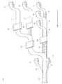
図5は,使い捨ておむつの製造工程の例を説明するための図であり,各シートを平面方向からみた状態を概念的に示している。特に,図5は,使い捨ておむつにおける吸収性本体を得るための工程を示したものである。図5に示された矢印は,装置の流れ方向を示している。なお,装置の流れ方向は,製造された使い捨ておむつの長手方向に一致する。
(3. Manufacturing method of disposable diapers)
Then, with reference to FIG. 5, the manufacturing method of a disposable diaper is demonstrated.
FIG. 5 is a diagram for explaining an example of the manufacturing process of the disposable diaper, and conceptually shows a state in which each sheet is viewed from the plane direction. In particular, FIG. 5 shows a process for obtaining an absorbent main body in a disposable diaper. The arrows shown in FIG. 5 indicate the flow direction of the apparatus. The flow direction of the device coincides with the longitudinal direction of the manufactured disposable diaper.

図5に示されるように,第1の原反ロール61からカバーシートの連続体6´が繰り出される。第1の原反ロール61の下流側には,第2の原反ロール62が位置している。第2の原反ロール62からは,バックシートの連続体2´が繰り出され,バックシートの連続体2´は,カバーシートの連続体6´の上に重ね合わされる。第2の原反ロール62の下流側には,第3の原反ロール63が位置している。第3の原反ロール63からは,下側コアラップシートの連続体32´が繰り出され,下側コアラップシートの連続体32´は,バックシートの連続体2´の上に重ね合わされる。また,第3の原反ロール63の下流側には,吸収性コア成型装置64が位置している。吸収性コア成型装置64は,下側コアラップシートの連続体32´の上に,吸収性コア33を供給する。  As shown in FIG. 5, the cover sheetcontinuous body 6 ′ is fed out from the firstoriginal fabric roll 61. A secondoriginal fabric roll 62 is located downstream of the firstoriginal fabric roll 61. Abacksheet continuum 2 ′ is fed out from the secondoriginal fabric roll 62, and thebacksheet continuum 2 ′ is superimposed on thecover sheet continuum 6 ′. A thirdoriginal fabric roll 63 is located downstream of the secondoriginal fabric roll 62. A lower corewrap sheet continuum 32 ′ is fed out from thethird web roll 63, and the lower corewrap sheet continuum 32 ′ is superimposed on theback sheet continuum 2 ′. In addition, an absorbentcore molding device 64 is located downstream of the thirdoriginal fabric roll 63. The absorbentcore molding device 64 supplies theabsorbent core 33 on the lower core wrap sheet continuum 32 '.

他方,上記第1〜3の原反ロール61,62,63とは別の流れに位置する第4の原反ロール65から上側コアラップシートの連続体31´が繰り出される。第4の原反ロール65の下流側には,ホットメルト塗布装置66が位置している。ホットメルト塗布装置66は,所定の間隔で上側コアラップシートの連続体31´の上にホットメルト接着剤を吐出する。このため,上側コアラップシートの連続体31´の上には,例えば装置の流れ方向に沿って直線状にホットメルト接着剤が塗布される。ホットメルト接着剤としては,ゴム系,ポリオレフィン系,酢酸ビニル系等の流動性のあるホットメルト接着剤から適宜選択することができる。また,ホットメルト塗布装置66によるホットメルト接着剤の塗布量を調節することにより,トップシートの連続体1´における相対的な凹凸の厚みの差を調整できる。例えば,ホットメルト接着剤の塗布量を多くすることにより,トップシートの連続体1´と上側コアラップシートの連続体31´の接合部における密着度が高くなるため,凹部の厚みが薄くなり,相対的に凸部の厚みを大きくすることができる。  On the other hand, acontinuous body 31 ′ of the upper core wrap sheet is fed out from a fourthoriginal roll 65 located in a flow different from the first to thirdoriginal rolls 61, 62, 63. A hotmelt coating device 66 is located downstream of the fourthraw roll 65. The hotmelt application device 66 discharges the hot melt adhesive onto the upper core wrap sheetcontinuous body 31 ′ at predetermined intervals. For this reason, a hot melt adhesive is applied on the upper corewrap sheet continuum 31 ′, for example, linearly along the flow direction of the apparatus. The hot-melt adhesive can be appropriately selected from fluid hot-melt adhesives such as rubber, polyolefin, and vinyl acetate. Further, by adjusting the application amount of the hot melt adhesive by the hotmelt application device 66, the difference in relative uneven thickness in the top sheet continuous body 1 'can be adjusted. For example, by increasing the amount of hot melt adhesive applied, the adhesiveness at the joint between thetop sheet continuum 1 ′ and the upper corewrap sheet continuum 31 ′ increases, so the thickness of the recesses decreases, The thickness of the convex portion can be relatively increased.

また,第5の原反ロール67からは,トップシートの連続体1´が繰り出される。第5の原反ロール67の下流には,シート延伸装置68が位置しており,シート延伸装置68は,第5の原反ロール67から繰り出されたトップシートの連続体1´を,その短手方向に延伸させる。シート延伸装置68は,例えば,トップシートの連続体1´の左右両側縁を引張して,第5の原反ロール67から繰り出された時点の初期状態と比較し,トップシートの連続体1´の短手方向の幅を,100.5%〜120%,101%〜115%,又は105〜110%に延伸させるものであることが好ましい。  Further, acontinuous body 1 ′ of the top sheet is fed out from the fifthoriginal fabric roll 67. Asheet stretching device 68 is located downstream of the fifthoriginal fabric roll 67, and thesheet stretching device 68 removes the top sheetcontinuous body 1 ′ fed out from the fifthoriginal fabric roll 67 from its short side. Stretch in the hand direction. For example, thesheet stretching device 68 pulls the left and right edges of thecontinuous body 1 ′ of the top sheet and compares it with the initial state when it is fed out from the fifthoriginal fabric roll 67. It is preferable that the width in the short direction is stretched to 100.5% to 120%, 101% to 115%, or 105 to 110%.

シート延伸装置68により延伸されたトップシートの連続体1´は,ホットメルト接着剤が塗布された上側コアラップシートの連続体31´の上に重ね合わされて,部分的に接合される。トップシートの連続体1´と上側コアラップシートの連続体31´の合流地点の下流側には,シート圧着装置69が位置している。シート圧着装置69は,トップシートの連続体1´と上側コアラップシートの連続体31´を平面方向に対してプレス圧力を付与し,両者を圧着させる。これにより,トップシートの連続体1´が上側コアラップシートの連続体31´が密着し,ホットメルト接着材が塗布された領域において,トップシートの連続体1´の繊維密度が高くなり,トップシートの連続体1´の厚みが小さくなる。他方,トップシートの連続体1´はシート延伸装置68により幅方向に延伸されているため,上側コアラップシートの連続体31´の上に接合された後,徐々に収縮し始める。これにより,ホットメルト接着材が塗布されていない領域においては,トップシート1に含まれる構成繊維の復元力によってトップシート1の厚みが増すようになる。このため,トップシートの連続体1´の接合領域における厚みと,トップシートの連続体1´の非接合領域における厚みの差が大きくなって,トップシートの連続体1´により顕著な凹凸が形成される。特に,シート圧着装置69によるプレス圧を調節することにより,トップシートの連続体1´における相対的な凹凸の厚みの差を調整できる。例えば,プレス圧を高くすることにより,トップシートの連続体1´と上側コアラップシートの連続体31´の接合部における密着度が高くなるため,凹部の厚みが薄くなり,相対的に凸部の厚みを大きくすることができる。  Thecontinuous body 1 ′ of the top sheet stretched by thesheet stretching device 68 is superposed on thecontinuous body 31 ′ of the upper core wrap sheet coated with the hot melt adhesive, and is partially joined. Asheet crimping device 69 is located on the downstream side of the joining point of thecontinuous body 1 ′ of the top sheet and thecontinuous body 31 ′ of the upper core wrap sheet. Thesheet crimping device 69 applies a pressing pressure to thecontinuum 1 ′ of the top sheet and thecontinuum 31 ′ of the upper core wrap sheet in the plane direction to crimp them together. As a result, the top sheetcontinuous body 1 ′ is in close contact with the upper core wrap sheetcontinuous body 31 ′, and the fiber density of the top sheetcontinuous body 1 ′ increases in the region where the hot melt adhesive is applied. The thickness of the sheet continuous body 1 'is reduced. On the other hand, since thecontinuous body 1 ′ of the top sheet is stretched in the width direction by thesheet stretching device 68, it is gradually contracted after being joined on thecontinuous body 31 ′ of the upper core wrap sheet. Thereby, in the area | region where the hot-melt-adhesive material is not apply | coated, the thickness of thetop sheet 1 comes to increase by the restoring force of the constituent fiber contained in thetop sheet 1. FIG. For this reason, the difference between the thickness in the joining region of the topsheetcontinuous body 1 ′ and the thickness in the non-joining region of the topsheetcontinuous body 1 ′ becomes large, and significant unevenness is formed by the topsheetcontinuous body 1 ′. Is done. In particular, by adjusting the pressing pressure by thesheet crimping device 69, it is possible to adjust the relative uneven thickness difference in the top sheetcontinuous body 1 ′. For example, by increasing the press pressure, the degree of adhesion at the joint between the top sheetcontinuous body 1 ′ and the upper core wrap sheetcontinuous body 31 ′ increases, so that the thickness of the concave portion is reduced and the convex portion is relatively Can be increased in thickness.

その後,図5に示されるように,カバーシートの連続体6´,バックシートの連続体2´,下側コアラップシートの連続体32´,及び吸収性コア33から構成される積層シートと,トップシートの連続体1´及び上側コアラップシートの連続体31´の接合シートが合流し,上記積層シート上に上記接合シートが重ね合わされる。積層シートと接合シートの合流地点の下流側には,第6の原反ロール70及び第7の原反ロール71が位置している。第6の原反ロール70及び第7の原反ロール71からは,それぞれ一対のサイドシートの連続体4´が繰り出され,上記積層シートと上記接合シートが重ね合わされたシートの連続体の左右両側縁を挟持するように折り返されて接合される。このとき,図示は省略するが,一対のサイドシートの連続体4´には,それぞれ伸長状態の立体ギャザー伸縮部材5が複数本固定される。  Thereafter, as shown in FIG. 5, a laminated sheet composed of acontinuous body 6 ′ of the cover sheet, acontinuous body 2 ′ of the back sheet, acontinuous body 32 ′ of the lower core wrap sheet, and theabsorbent core 33; The joining sheet of thecontinuous body 1 ′ of the top sheet and thecontinuous body 31 ′ of the upper core wrap sheet merges, and the joining sheet is superimposed on the laminated sheet. A sixthoriginal fabric roll 70 and a seventhoriginal fabric roll 71 are located on the downstream side of the joining point of the laminated sheet and the joining sheet. From the sixthoriginal fabric roll 70 and the seventhoriginal fabric roll 71, a pair of side sheet continuums 4 'are fed out, and both the left and right sides of the sheet continuum in which the laminated sheet and the joining sheet are overlaid. It is folded and joined so as to sandwich the edge. At this time, although not shown, a plurality of three-dimensional gatheredelastic members 5 are fixed to thecontinuous body 4 ′ of the pair of side sheets.

以上の工程により,吸収性本体43を構成するシートの連続体43´が得られる。このため,その後,吸収性本体を構成するシートの連続体43´に対して,前身頃外装体41及び後身頃外装体42を接着した後,吸収性本体43の一端部に前身頃外装体41が取り付けられ,他端部に後身頃外装体42が取り付けられた状態となるように個別に裁断することにより,使い捨ておむつを製造することができる。  Through the above steps, acontinuous sheet 43 ′ constituting the absorbentmain body 43 is obtained. Therefore, after the frontbody exterior body 41 and the rearbody exterior body 42 are bonded to thecontinuous body 43 ′ of the sheet constituting the absorbent body, the frontbody exterior body 41 is then attached to one end of theabsorbent body 43. Is attached, and the disposable diaper can be manufactured by individually cutting so that the rearbody exterior body 42 is attached to the other end.

以上,使い捨ておむつの製造工程の一例を説明したが,本発明に係る使い捨ておむつの製造方法はこれに限定されるものではない。例えば,上側コアラップシートの連続体31´にホットメルト接着剤と塗布する代わりに,トップシートの連続体1´と上側コアラップシートの連続体31´の間に介在する補助シート7の連続体に対して,ホットメルト接着剤を塗布し,トッププシート1の連続体と補助シート7の連続体を部分的に接合することとしてもよい。また,使い捨ておむつの製造方法に使用される吸収性コア成型装置64,ホットメルト塗布装置66,シート延伸装置68,及びシート圧着装置69などの各種装置には,適宜公知の装置を利用することができる。  As mentioned above, although an example of the manufacturing process of a disposable diaper was demonstrated, the manufacturing method of the disposable diaper which concerns on this invention is not limited to this. For example, instead of applying hot melt adhesive to the upper corewrap sheet continuum 31 ′, a continuum of theauxiliary sheet 7 interposed between thetop sheet continuum 1 ′ and the upper corewrap sheet continuum 31 ′. On the other hand, a hot melt adhesive may be applied to partially join the continuous body of thetop sheet 1 and the continuous body of theauxiliary sheet 7. In addition, various known devices such as an absorbentcore molding device 64, a hotmelt coating device 66, asheet stretching device 68, and asheet crimping device 69 used in the manufacturing method for disposable diapers may be appropriately used. it can.

本発明は,乳幼児用や高齢者用の使い捨ておむつ及びその製造方法に関する。従って,本発明は,育児及び介護に関する産業において好適に利用し得る。  The present invention relates to a disposable diaper for infants and the elderly and a method for producing the same. Therefore, the present invention can be suitably used in industries related to childcare and nursing care.

1 トップシート
2 バックシート
3 吸収体
4 サイドシート
4a 外側ギャザー部
4b 内側ギャザー部
5 立体ギャザー伸縮部材
6 カバーシート
7 補助シート
11 凹部
12 凸部
13 接合領域
14 非接合領域
31 上側コアラップシート
32 下側コアラップシート
33 吸収性コア
41 前身頃外装体
42 後身頃外装体
43 吸収性本体
51 タミー伸縮部材
52 ウエスト伸縮部材
61 第1の原反ロール
62 第2の原反ロール
63 第3の原反ロール
64 吸収性コア成形装置
65 第4の原反ロール
66 ホットメルト塗布装置
67 第5の原反ロール
68 シート延伸装置
69 シート圧着装置
70 第6の原反ロール
71 第7の原反ロール
100 使い捨ておむつ
DESCRIPTION OFSYMBOLS 1Top sheet 2Back sheet 3Absorber 4Side sheet 4a Outer gatherpart 4b Inner gatherpart 5 Three-dimensional gather expansion /contraction member 6Cover sheet 7Auxiliary sheet 11Concave part 12Convex part 13Non-joining area 31 Uppercore wrap sheet 32 Below Sidecore wrap sheet 33Absorbent core 41 Frontbody exterior body 42 Rearbody exterior body 43Absorbent body 51 Tammyelastic member 52 Waistelastic member 61 Firstoriginal fabric roll 62 Secondoriginal fabric roll 63 Thirdoriginal fabric Roll 64 Absorbentcore forming device 65 Fourthraw fabric roll 66 Hotmelt coating device 67 Fifthoriginal fabric roll 68Sheet stretching device 69Sheet crimping device 70 Sixthoriginal fabric roll 71 Seventhoriginal fabric roll 100 Disposable Diapers

Claims (1)

Translated fromJapanese
トップシート(1)と,バックシート(2)と,前記トップシート(1)と前記バックシート(2)の間に介在された吸収体(3)を有し,
前記吸収体(3)は,前記トップシート(1)側に位置する上側コアラップシート(31)と,前記バックシート(2)側に位置する下側コアラップシート(32)と,前記上側コアラップシート(31)と前記下側コアラップシート(32)により封入された吸収性コア(33)を有する
吸収性物品の製造方法であって,
前記バックシート(2)上に前記下側コアラップシート(32)が配設され,前記下側コアラップシート(32)上に前記吸収性コア(33)が配設された物品を得る工程と,
前記トップシート(1)と前記上側コアラップシート(31)を部分的に接合して,接合領域(13)と非接合領域(14)を有する前記トップシート(1)前記上側コアラップシート(31)接合体を得る工程と,
前記接合体を平面側から押圧して,前記トップシート(1)に,前記接合領域(13)において相対的に厚みが小さくなった凹部(11),前記非接合領域(14)において相対的に厚みが大きくなった凸部(12)を形成する工程と,
前記トップシート(1)に前記凹部(11)と前記凸部(12)を形成した後に,前記物品上に前記接合体を接合する工程と,を行う
吸収性物品の製造方法。
A top sheet (1), a back sheet (2), and an absorber (3) interposed between the top sheet (1) and the back sheet (2);
The absorber (3) includes an upper core wrap sheet (31) located on the top sheet (1) side, a lower core wrap sheet (32) located on the back sheet (2) side, and the upper core A method of manufacturing an absorbent article having an absorbent core (33) enclosed by a wrap sheet (31) and the lower core wrap sheet (32),
Obtaining an article in which the lower core wrap sheet (32) is disposed on the back sheet (2) and the absorbent core (33) is disposed on the lower core wrap sheet (32); ,
Thejoined top sheet (1) and the upper core wrap sheet (31)partly, thejoining region (13)and said topsheethaving a non-bonding region (14) (1) upper core wrap sheet ( 31) obtaininga joined body;
The joined body is pressed from the plane side, and relativeto the top sheet (1) in the concave portion (11)having a relatively small thickness in the joining region (13)and in the non-joining region (14). Forming a convex portion (12) having an increased thickness on the substrate,
A method of manufacturing an absorbent article, comprising:forming the concave portion (11) and the convex portion (12) on the top sheet (1), and then joining the joined body on the article.
JP2012036110A2012-02-222012-02-22 Method for manufacturing absorbent articleExpired - Fee RelatedJP5867152B2 (en)

Priority Applications (1)

Application NumberPriority DateFiling DateTitle
JP2012036110AJP5867152B2 (en)2012-02-222012-02-22 Method for manufacturing absorbent article

Applications Claiming Priority (1)

Application NumberPriority DateFiling DateTitle
JP2012036110AJP5867152B2 (en)2012-02-222012-02-22 Method for manufacturing absorbent article

Publications (2)

Publication NumberPublication Date
JP2013169388A JP2013169388A (en)2013-09-02
JP5867152B2true JP5867152B2 (en)2016-02-24

Family

ID=49263742

Family Applications (1)

Application NumberTitlePriority DateFiling Date
JP2012036110AExpired - Fee RelatedJP5867152B2 (en)2012-02-222012-02-22 Method for manufacturing absorbent article

Country Status (1)

CountryLink
JP (1)JP5867152B2 (en)

Families Citing this family (11)

* Cited by examiner, † Cited by third party
Publication numberPriority datePublication dateAssigneeTitle
US10064766B2 (en)2014-09-122018-09-04The Procter & Gamble CompanyNonwoven material having discrete three-dimensional deformations that are configured to collapse in a controlled manner
US10076898B2 (en)2014-09-122018-09-18The Procter & Gamble CompanyApparatus having forming members with surface texture for making nonwoven material having discrete three-dimensional deformations with wide base openings
RU2017106030A (en)2014-09-122018-10-12Дзе Проктер Энд Гэмбл Компани Non-woven material with discrete three-dimensional deforming elements characterized by a wide mouth and various fiber concentrations
CN106794100A (en)2014-09-122017-05-31宝洁公司Absorbent article with mark and/or color
JP5866045B1 (en)*2015-04-222016-02-17ユニ・チャーム株式会社 Absorbent articles
JP5963987B1 (en)*2016-02-292016-08-03ユニ・チャーム株式会社 Absorbent articles
EP3216434A1 (en)2016-03-082017-09-13The Procter and Gamble CompanyAbsorbent article comprising a topsheet/acquisition web laminate
JP6427520B2 (en)2016-03-292018-11-21ユニ・チャーム株式会社 Absorbent articles
EP3554439B1 (en)*2016-12-192021-11-10The Procter & Gamble CompanyAbsorbent article with absorbent core
WO2018161288A1 (en)2017-03-092018-09-13The Procter & Gamble CompanyThree-dimensional materials having apertures and voids
JP2023063221A (en)*2021-10-222023-05-09王子ホールディングス株式会社absorbent article

Family Cites Families (8)

* Cited by examiner, † Cited by third party
Publication numberPriority datePublication dateAssigneeTitle
JP4229868B2 (en)*2004-04-272009-02-25花王株式会社 Solid nonwoven fabric
JP5328089B2 (en)*2006-06-232013-10-30ユニ・チャーム株式会社 Multilayer nonwoven fabric and method for producing multilayer nonwoven fabric
JP4834529B2 (en)*2006-11-302011-12-14大王製紙株式会社 Absorbent articles
JP2009102774A (en)*2007-10-242009-05-14Kao Corp Nonwoven manufacturing method
JP2010148730A (en)*2008-12-252010-07-08Kao CorpSurface sheet of absorbent article
JP5631035B2 (en)*2010-03-292014-11-26ユニ・チャーム株式会社 Nonwoven sheet
JP5543268B2 (en)*2010-05-102014-07-09大王製紙株式会社 Disposable absorbent article
JP5972584B2 (en)*2012-01-312016-08-17大王製紙株式会社 Absorbent articles

Also Published As

Publication numberPublication date
JP2013169388A (en)2013-09-02

Similar Documents

PublicationPublication DateTitle
JP5867152B2 (en) Method for manufacturing absorbent article
TWI706773B (en) Stretchable structure of absorbent article and manufacturing method thereof
WO2008062873A1 (en)Absorptive article and method of producing the same
CN104837455B (en) disposable diapers
JP5977928B2 (en) Absorbent articles
JP6095207B2 (en) Absorbent articles
CN108348374A (en)Absorbent commodity
JP6124282B2 (en) Absorbent article and method for forming fit stretchable part
JP2017148111A (en) Pants-type absorbent article
JP2018038465A (en)Disposable diaper
JP2014104261A5 (en)
JP6830134B2 (en) Disposable diapers and how to make them
JP5946182B2 (en) Disposable diapers
JP6301422B2 (en) Absorbent articles
JP2020081313A (en) Absorbent article
JP2016158799A (en)Underpants type absorbent article
JP2018007954A (en)Disposable diaper
JP6297438B2 (en) Disposable wear
JP5413000B2 (en) Fastening tape, manufacturing method of fastening tape, and tape-type disposable diaper
JP4966841B2 (en) Disposable pants-type diapers
JP2016182169A (en)Underpants type absorbent article
JP5980262B2 (en) Disposable diapers
JP2003062008A (en)Absorptive article and its manufacturing method
JP2015198798A (en) Absorbent articles
JP6265110B2 (en) Absorbent article and manufacturing method thereof

Legal Events

DateCodeTitleDescription
A711Notification of change in applicant

Free format text:JAPANESE INTERMEDIATE CODE: A711

Effective date:20130605

A621Written request for application examination

Free format text:JAPANESE INTERMEDIATE CODE: A621

Effective date:20140801

A977Report on retrieval

Free format text:JAPANESE INTERMEDIATE CODE: A971007

Effective date:20150417

A131Notification of reasons for refusal

Free format text:JAPANESE INTERMEDIATE CODE: A131

Effective date:20150602

A521Request for written amendment filed

Free format text:JAPANESE INTERMEDIATE CODE: A523

Effective date:20150731

TRDDDecision of grant or rejection written
A01Written decision to grant a patent or to grant a registration (utility model)

Free format text:JAPANESE INTERMEDIATE CODE: A01

Effective date:20151208

A61First payment of annual fees (during grant procedure)

Free format text:JAPANESE INTERMEDIATE CODE: A61

Effective date:20151221

R150Certificate of patent or registration of utility model

Ref document number:5867152

Country of ref document:JP

Free format text:JAPANESE INTERMEDIATE CODE: R150

R250Receipt of annual fees

Free format text:JAPANESE INTERMEDIATE CODE: R250

R250Receipt of annual fees

Free format text:JAPANESE INTERMEDIATE CODE: R250

R250Receipt of annual fees

Free format text:JAPANESE INTERMEDIATE CODE: R250

LAPSCancellation because of no payment of annual fees

[8]ページ先頭

©2009-2025 Movatter.jp