JP5866548B1 - Wearable camera - Google Patents
Wearable cameraDownload PDFInfo
- Publication number
- JP5866548B1 JP5866548B1JP2014186486AJP2014186486AJP5866548B1JP 5866548 B1JP5866548 B1JP 5866548B1JP 2014186486 AJP2014186486 AJP 2014186486AJP 2014186486 AJP2014186486 AJP 2014186486AJP 5866548 B1JP5866548 B1JP 5866548B1
- Authority
- JP
- Japan
- Prior art keywords
- camera
- recording
- terminal
- charging
- cable
- Prior art date
- Legal status (The legal status is an assumption and is not a legal conclusion. Google has not performed a legal analysis and makes no representation as to the accuracy of the status listed.)
- Expired - Fee Related
Links
Images


Classifications
- H—ELECTRICITY
- H04—ELECTRIC COMMUNICATION TECHNIQUE
- H04N—PICTORIAL COMMUNICATION, e.g. TELEVISION
- H04N5/00—Details of television systems
- H04N5/76—Television signal recording
- H04N5/907—Television signal recording using static stores, e.g. storage tubes or semiconductor memories
- G—PHYSICS
- G06—COMPUTING OR CALCULATING; COUNTING
- G06F—ELECTRIC DIGITAL DATA PROCESSING
- G06F1/00—Details not covered by groups G06F3/00 - G06F13/00 and G06F21/00
- G06F1/16—Constructional details or arrangements
- G06F1/1613—Constructional details or arrangements for portable computers
- G06F1/163—Wearable computers, e.g. on a belt
- G—PHYSICS
- G06—COMPUTING OR CALCULATING; COUNTING
- G06F—ELECTRIC DIGITAL DATA PROCESSING
- G06F1/00—Details not covered by groups G06F3/00 - G06F13/00 and G06F21/00
- G06F1/26—Power supply means, e.g. regulation thereof
- G06F1/263—Arrangements for using multiple switchable power supplies, e.g. battery and AC
- G—PHYSICS
- G06—COMPUTING OR CALCULATING; COUNTING
- G06F—ELECTRIC DIGITAL DATA PROCESSING
- G06F1/00—Details not covered by groups G06F3/00 - G06F13/00 and G06F21/00
- G06F1/26—Power supply means, e.g. regulation thereof
- G06F1/266—Arrangements to supply power to external peripherals either directly from the computer or under computer control, e.g. supply of power through the communication port, computer controlled power-strips
- H—ELECTRICITY
- H04—ELECTRIC COMMUNICATION TECHNIQUE
- H04N—PICTORIAL COMMUNICATION, e.g. TELEVISION
- H04N23/00—Cameras or camera modules comprising electronic image sensors; Control thereof
- H04N23/60—Control of cameras or camera modules
- H04N23/65—Control of camera operation in relation to power supply
- H—ELECTRICITY
- H04—ELECTRIC COMMUNICATION TECHNIQUE
- H04N—PICTORIAL COMMUNICATION, e.g. TELEVISION
- H04N5/00—Details of television systems
- H04N5/76—Television signal recording
- H04N5/765—Interface circuits between an apparatus for recording and another apparatus
- H04N5/77—Interface circuits between an apparatus for recording and another apparatus between a recording apparatus and a television camera
- H04N5/772—Interface circuits between an apparatus for recording and another apparatus between a recording apparatus and a television camera the recording apparatus and the television camera being placed in the same enclosure
Landscapes
- Engineering & Computer Science (AREA)
- Theoretical Computer Science (AREA)
- General Engineering & Computer Science (AREA)
- Computer Hardware Design (AREA)
- Multimedia (AREA)
- Signal Processing (AREA)
- General Physics & Mathematics (AREA)
- Physics & Mathematics (AREA)
- Human Computer Interaction (AREA)
- Power Engineering (AREA)
- Studio Devices (AREA)
- Details Of Cameras Including Film Mechanisms (AREA)
- Accessories Of Cameras (AREA)
Abstract
Translated fromJapaneseDescription
Translated fromJapanese本発明は、携帯可能であり録画を行うことができるウェアラブルカメラに関する。The present invention relates to awearable camera that is portable and capable of recording.
近年、警察官や警備員の業務を支援するために、ウェアラブルカメラの導入が検討されている。
ウェアラブルカメラを用いた認証システムが開発されており、例えば特許文献1に記載されたものがある。特許文献1に記載された認証システムは、カメラ付き懐中電灯である携帯端末と、該携帯端末の充電機能を有するクレードルと、該クレードルに接続されたパーソナルコンピュータを有し、当該システムが警備に用いられる場合、巡回パトロールを始めようとする警備員(ユーザ)が、まず個人認証情報の入力を含む認証作業を実施した後、携帯端末をクレードルから抜き取る。この抜き取りに応答して、該携帯端末にて録画が開始され、パーソナルコンピュータに接続された外部機器に対してパーソナルコンピュータから認証結果データを含む警備開始通知メールが送信される。警備員は、巡回を終えて携帯端末をクレードルに戻すと、警備終了通知メールが外部機器に送信される。その後、携帯端末における録画は終了されて、撮像データはパーソナルコンピュータ内の主記録媒体に転送される。In recent years, the introduction of wearable cameras has been considered to support the operations of police officers and guards.
An authentication system using a wearable camera has been developed. For example, there is one described in
ところで、上述した特許文献1に記載された認証システムにおいては、携帯端末であるカメラをクレードルから引き抜いたときに録画を開始するようにしているが、使用状況によりクレードルから引き抜いた直後に録画する必要が無い場合がある。そのため、ユーザが任意に録画するようにすると、必要なときに録画できない恐れがあるが、常時録画を行うようにすると無駄な録画が行われるとともに、携帯端末の記憶容量を無駄にしてしまうという課題がある。 By the way, in the authentication system described in
本発明は、係る事情に鑑みてなされたものであり、必要なときにのみ録画が可能なウェアラブルカメラを提供することを目的とする。The present invention has been made in view of such circumstances, and an object thereof is to provide awearable camera capable of recording only when necessary.
本発明は、警察官等が装着するウェアラブルカメラであって、撮像部と、前記撮像部から出力される画像情報の記録媒体への記録を開始するか否かを制御する記録制御部と、を備え、パトロール中に車載パーソナルコンピュータと接続し、前記ウェアラブルカメラに電源を供給する第1のケーブル、又はパトロール中以外にACアダプタと接続し、前記ウェアラブルカメラに電源を供給する第2のケーブルに接続可能であり、前記記録制御部は、前記第1のケーブルとの接続状態が解除されると前記撮像部から出力される画像情報の記録を開始するとともに、前記第2のケーブルとの接続状態が解除されると前記撮像部から出力される画像情報の記録は開始しない、ウェアラブルカメラである。This onsetMing isa wearable camera policeman wears, a recording control section for controlling the imagingunit, whether to start the recording to the recording medium of the image information output from theprevious SL imaging unit Afirst cable for connecting to an in-vehicle personal computer during patrol and supplying power to the wearable camera, or a second cable for connecting to an AC adapter other than during patrol and supplying power to the wearable camera When the connection state with the first cable is released, the recording control unit starts recording image information output from the imaging unit and connects with the second cable. When the state is released, the wearable camera does not start recording the image information output from the imaging unit .
本発明によれば、必要なときにのみ録画が可能となる。 According to the present invention, recording is possible only when necessary.
以下、本発明を実施するための好適な実施の形態について、図面を参照して詳細に説明する。 DESCRIPTION OF EXEMPLARY EMBODIMENTS Hereinafter, preferred embodiments for carrying out the invention will be described in detail with reference to the drawings.
(実施の形態1)
図1は、本発明の実施の形態1に係るカメラの外観を示す斜視図であり、同図の(a)は正面側を示し、同図の(b)は裏面側を示す。この場合、同図の(b)は上下逆さまにした状態を示している。同図の(a)、(b)に示すように、カメラ1は、録画可能なカメラであって、縦長方形状に形成されている。カメラ1の本体正面の上部中央にレンズ11が設けられており、本体上面には録画ボタン12とスナップショットボタン13が設けられている。また、カメラ1の本体正面の下部には3個のLED(発光ダイオード)14〜16が等間隔で設けられており、カメラ1の本体右面にはWi−Fi(登録商標)ボタン17が設けられている。また、カメラ1の本体下面には、パーソナルコンピュータ等の外部機器と接続するためのコンタクトターミナル19が設けられている。なお、本実施の形態に係るカメラ1は、警察署において使用する場合を想定したものであるが、警察署以外の様々な事業所で使用できることは言うまでもない。なお、カメラ1は、携帯可能なカメラであるため、例えば、身体に装着して利用するウェアラブルカメラ等である。(Embodiment 1)
1A and 1B are perspective views showing the appearance of a camera according to
録画ボタン12は、動画撮像時に操作するボタンであり、これを押下することで動画の撮影が開始される。スナップショットボタン13は静止画撮像時に操作するボタンであり、これを押下することで静止画が撮像される。LED14は、カメラ1の電源投入状態を示すランプであり、電源ボタン(図示略)が押下されることで点灯する。LED15は、カメラ1の録画状態を示すランプであり、録画ボタン12が押下されることで点灯する。LED15は録画中継続して点灯する。LED16は、Wi−Fiによる無線通信状態を示すランプであり、Wi−Fiボタン17が押下されることで点灯する。特に、LED16は、2色点灯が可能なLEDであり、Wi−Fiボタン17の押下によって異なる色で点灯する。すなわち、1回目の押下によって第1色(例えば、赤)で点灯し、2回目の押下によって第2色(例えば、緑)で点灯し、3回目の押下によって消灯する。これらの状態がWi−Fiボタン17の押下によって繰り返される。つまり、Wi−Fiボタン17の押下毎に第1色点灯→第2色点灯→消灯→第1色点灯→・・・が繰り返される。 The
カメラ1には通信に関するモードとして、アクセスポイントモードとステーションモードが用意されており、Wi−Fiボタン17の押下が行われる毎にアクセスポイントモード→ステーションモード→通信オフ→アクセスポイントモード…と、モードが切り替わる。そして、モードの切り替えに応じてLED16の点灯色が変わる。すなわち、アクセスポイントモード時には第1色で点灯し、ステーションモード時には第2色で点灯する。なお、通信オフ時には消灯する。 As the communication mode, the
コンタクトターミナル19には、図1(b)に示すように、「充電端子V+(以下、V+端子とも言う)」、「CON.DET端子(検出端子)」、「データ端子D−,D+」及び「GND端子(グランド端子)」が設けられている。充電端子V+は、充電電圧が印加される端子である。CON.DET端子は、電圧変化を検出するための端子である。データ端子D−,D+は、パーソナルコンピュータにカメラ1で撮像した撮像データ等を送信するための端子である。コンタクトターミナル19は、後述する充電ケーブル又はACアダプタと接続される。 As shown in FIG. 1B, the
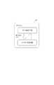
図2は、カメラ1の概略構成を示すブロック図である。同図において、カメラ1は、上述した録画ボタン12、スナップショットボタン13、LED14〜16、Wi−Fiボタン17及びコンタクトターミナル19の他に、撮像部100、GPIO(General Purpose Input/Output)101、RAM(Random Access Memory)102、ROM(Read Only Memory)103、SDメモリ104、EEPROM(Electrically Erasable Programmable Read-Only Memory)105、RTC(Real-Time Clock)106、GPS(Global Positioning System)107、CPU(Central Processing Unit)108、物理層(Physical Layer)109、Wi−Fi通信部110、USB(Universal Serial Bus)111、電源部112及びバッテリ113を有している。なお、CPU108は、検出部及び記録制御部に対応する。なお、SDメモリ104は、カメラ1から着脱可能な媒体であり、具体的にはSDカード等であるが、カメラ1本体に内蔵されていても良い。 FIG. 2 is a block diagram illustrating a schematic configuration of the
撮像部100は、上述したレンズ11の他に、CCD(Charge Coupled Device)型イメージセンサやCMOS(Complementary Metal Oxide Semiconductor)型イメージセンサ等の固体撮像素子を有しており、撮像データを出力する。GPIO101は、パラレルインタフェースであり、上述した録画ボタン12、スナップショットボタン13、LED14〜16及びWi−Fiボタン17とCPU108との間の信号の入出力を行う。 In addition to the
RAM102は、CPU108の動作において使用されるワークメモリである。ROM103は、CPU108を制御するためのプログラムを記憶する。SDメモリ104は、撮像部100から出力される撮像データを記憶する。SDメモリ104は、カメラ1の本体に対して取付け/取外しが可能となっている。EEPROM105は、カメラ1のシリアル番号を記憶する。RTC106は、現在時刻情報を出力する。GPS107は、現在位置情報を出力する。物理層109は、OSI(Open Systems Interconnection)参照モデルの第1層であり、Wi−Fi通信部110とCPU108との接続を規定する。Wi−Fi通信部110は、Wi−Fi通信を行う。USB111は、シリアルバスであり、カメラ1とパーソナルコンピュータ(後述する)の接続を可能とする。電源部112は、コンタクトターミナル19を介して供給される電源でバッテリ113を充電する。バッテリ113は、カメラ1の各部に電源を供給する。 The
CPU108は、ROM103に記憶されたプログラムに従って動作する。CPU108は、その動作において、RAM102を使用し、またRTC106より現在時刻情報を得るとともに、GPS107より現在位置情報を得る。また、CPU108は、録画ボタン12、スナップショットボタン13及びWi−Fiボタン17の各ボタンの押下の検出を行い、操作があったボタンに対する処理を行う。すなわち、録画ボタン12が押下された場合は、撮像部100から出力される撮像データを動画像としてSDメモリ104に保存する。また、スナップショットボタン13が押下された場合は、当該ボタン13が押されたときの撮像データを静止画像としてSDメモリ104に保存する。また、録画ボタン12が押下された場合はLED15を点灯させる。Wi−Fiボタン17が押下された場合はWi−Fi通信部110を使用してWi−Fi通信を行う。Wi−Fiボタン17が押下された場合はLED16を点灯させるが、通信に関するモードがアクセスポイントモードであれば第1色で点灯させ、ステーションモードであれば第2色で点灯させる。CPU108は、動画撮像、静止画撮像及びWi−Fi通信を行う。 The
図3は、充電ケーブル4(第1のケーブル)によるカメラ1とパーソナルコンピュータ3の接続状態を示す図である。同図において、充電ケーブル4の一方の端には、カメラ1のコンタクトターミナル19に接続可能なプラグ41が取付けられており、他方の端にはパーソナルコンピュータ3のレセプタクル31に接続可能なプラグ42が取付けられている。充電ケーブル4は、パーソナルコンピュータ3のレセプタクル31のVBUS(5V)端子とカメラ1のコンタクトターミナル19のV+端子及びCON.DET端子とを接続する。また、充電ケーブル4は、レセプタクル31のD−端子とコンタクトターミナル19のD−端子、レセプタクル31のD+端子とコンタクトターミナル19のD+端子、レセプタクル31のGND端子とコンタクトターミナル19のGND端子をそれぞれ接続する。また、コンタクトターミナル19に接続可能なプラグ41は、パーソナルコンピュータ3のレセプタクル31に接続可能なプラグ42よりも接続が外れやすくなっており、例えば、プラグ41は、磁力で固定されるようなマグネット端子等でコンタクトターミナル19と接続し、プラグ42はUSB端子等を差し込むことでレセプタクル31と接続している。 FIG. 3 is a diagram showing a connection state between the
充電ケーブル4においてカメラ1のコンタクトターミナル19の充電端子V+とCON.DET端子を電気的に接続することで、充電ケーブル4のプラグ41がカメラ1のコンタクトターミナル19から外れた場合に、カメラ1のコンタクトターミナル19のCON.DET端子に充電電圧が印加されなくなる。カメラ1のCPU108は、コンタクトターミナル19のCON.DET端子に充電電圧が印加されなくなったことを検出することで、撮像部100から出力される撮像データのSDメモリ104への記録を開始する。すなわち、充電ケーブル4のプラグ41がカメラ1のコンタクトターミナル19から外れた場合に録画が開始される。 In the charging
図4は、カメラ1のコンタクトターミナル19のV+端子における充電電圧とCON.DET端子における電圧の変化を示す図である。カメラ1を充電ケーブル4でパーソナルコンピュータ3と接続すると、カメラ1に充電ケーブル4が接続された時点(時刻T1)で、カメラ1のコンタクトターミナル19のV+端子に5Vの充電電圧が印加されるとともに、コンタクトターミナル19のCON.DET端子にも5Vの充電電圧が印加される。カメラ1に充電電圧が印加されることで、カメラ1のバッテリ113の充電が行われる。また、カメラ1のコンタクトターミナル19のCON.DET端子に充電電圧が印加されることで、CON.DET端子における信号レベルが「H(Hi)」になる。 4 shows the charging voltage at the V + terminal of the
その後、カメラ1から充電ケーブル4が外れると、その時点(時刻T2)でカメラ1のコンタクトターミナル19のV+端子への充電電圧の供給が停止し、また同時にカメラ1のコンタクトターミナル19のCON.DET端子への充電電圧の供給が停止する。カメラ1のコンタクトターミナル19のCON.DET端子への充電電圧の供給が停止されることで、カメラ1のコンタクトターミナル19のCON.DET端子における信号レベルが「H」から「L(Low)」になり、カメラ1はこの「H」から「L」に変化するタイミングを検知しこのタイミングで録画を開始する。すなわち、カメラ1のCPU108は、信号レベルの変化を検知すると撮像部100から出力される画像データを取り込んで、SDメモリ104に記録する。なお、CON.DET端子における「H」から「L」への信号レベルの変化は検知できればよく、必要なタイミングが検知できれば、「L」から「H」を検知するようにしてもよく、また、一方の信号レベルが0である必要も無い。さらに、本実施の形態では、信号レベルを電圧としているが、他のものでもよく、例えば、外部と通信中か否かを検知対象としてもよい。 Thereafter, when the charging
一方、パーソナルコンピュータではなく電源から直接カメラ1を充電する場合、ACアダプタ5(第2のケーブル、図5参照)を使用して、これをカメラ1のコンタクトターミナル19に接続する。図5は、カメラ1とACアダプタ5の接続状態を示す図である。同図において、ACアダプタ5の充電電圧出力側のケーブル51には、カメラ1のコンタクトターミナル19に接続可能なプラグ52が取付けられている。このプラグ52をカメラ1のコンタクトターミナル19に接続することで、プラグ52のVBUS(5V)がカメラ1のコンタクトターミナル19のV+端子に接続され、またプラグ52のGNDがカメラ1のコンタクトターミナル19のGNDに接続される。ACアダプタ5には、充電ケーブル4と異なり、カメラ1のコンタクトターミナル19のCON.DET端子と接続する端子がないので、ACアダプタ5の抜き差しにより、CON.DET端子における信号レベルが変化しない。そのため、カメラ1からACアダプタ5を外してもカメラ1は録画を開始しない。なお、図5では、ACアダプタ5に直接接続するようにしているが、利便性を考慮してクレードルを利用してカメラ1をACアダプタ5に接続しても良い。 On the other hand, when charging the
図6は、カメラ1のコンタクトターミナル19のV+端子における充電電圧とCON.DET端子における電圧の変化を示す図である。同図において、カメラ1にACアダプタ5が接続された時点(時刻T1)で、カメラ1のコンタクトターミナル19のV+端子に5Vの充電電圧が印加される。充電電圧が印加されることで、カメラ1のバッテリ113の充電が開始される。このとき、CON.DET端子における信号レベルは「L」のままである。その後、カメラ1からACアダプタ5が外される。その時点(時刻T2)でカメラ1のコンタクトターミナル19のV+端子への充電電圧の供給が停止するが、コンタクトターミナル19のCON.DET端子における信号レベルが「L」のままであり、つまり信号レベルが変化しないので、カメラ1における録画は開始されない。 6 shows the charging voltage at the V + terminal of the
なお、パーソナルコンピュータ3は、カメラ1に充電用の電源を供給する以外に、カメラ1に保存されている撮像データを取り込んで保存する。また、録画を停止するには、カメラ1に充電ケーブル4を接続する、手動で録画を停止する、又は、タイマーを利用して所定の時間のみを録画するようにしても構わない。 Note that the
上記説明したカメラ1に関するシステムについて、具体的な使用例について、以下詳細に説明する。なお、ここでの例は、あくまで一例であり、下記に限定されない。警察で利用する場合、警察署内では、ACアダプタ5を用いてカメラ1を充電し、パトロールカー(図示略、以下“パトカー”と呼ぶ)内では、パトカー内に搭載されているパーソナルコンピュータ3から充電ケーブル4を用いてカメラ1を充電する。 About the system regarding the
上記のような使用状況において、パトロール前に警察官は、まず警察署内で充電されているカメラ1を持ち出し、身体(頭、肩、胸等)に装着する。この際、事件等は起こっておらず録画する必要は無いため、ACアダプタ5から抜いた時点では録画を行わない(録画を開始しない)。つまり、図5、図6に示した動作を行う。 Under the above-mentioned usage situation, before the patrol, the police officer first takes out the
カメラ1を警察署から持ち出した警察官は、パトカーに乗ってパトロール業務を行う。この際、パトカー内では充電ケーブル4を介してパーソナルコンピュータ3から充電を行う。なお、パトカーには、パーソナルコンピュータ3に接続されカメラ1とは異なる車載カメラが設けられており、パトカーでのパトロール中は、この車載カメラにて録画を行う。そして、事件等が起こった場合、パトカーで現場近くまで向かい車から降りてその現場に向かう。その際、パトカーから離れるため車載カメラでは、現場の録画を行うことができない。そのため、カメラ1にて録画を行うが、この際、警察官が録画ボタンを押して録画するようにすると、警察官が録画し忘れる可能性がある。そのため、カメラ1が充電ケーブル4から抜けたとき自動的に録画できるようにする。つまり、図3、図4に示した動作を行う。 The police officer who took the
また、上述したように、カメラ1と充電ケーブル4は、マグネット端子で接続されているので、警察官が意識してケーブルを抜くことが不要、つまり一定の力がかかれば、簡単に充電ケーブル4が抜けるので、パトカーから飛び出す場合にも、警察官が意識することなく、録画を開始させることができる。 Further, as described above, since the
以上のように、カメラ1を利用することで、パトロール中、必要なとき(車載カメラが録画できないとき等)に自動的に録画することができる。 As described above, by using the
なお、撮像データに関しては、所定のタイミングで、警察署のサーバ、若しくはクラウドサーバにアップロードして、車載カメラの撮像データと、カメラ1の撮像データとをまとめて管理する。この際、車載カメラの撮像データと、カメラ1の撮像データをどの警察官が撮像したかも合わせて管理するため、車載カメラ、カメラ1共にパーソナルコンピュータ3を介してユーザID等で警察官を特定できるようにする。なお、カメラ1から上記のサーバに直接アップロードする場合には、例えば、カメラ1に上記ユーザIDを送信し、カメラ1がアップロードする際に、撮像データをユーザIDと共にサーバに送信すればよいし、パーソナルコンピュータ3を介してカメラ1の撮像データを送信する場合には、パーソナルコンピュータ3にて、車載カメラの撮像データと、カメラ1の撮像データ、ユーザIDを合わせてサーバに送信すればよい。 The imaging data is uploaded to a police station server or a cloud server at a predetermined timing, and the imaging data of the in-vehicle camera and the imaging data of the
また、カメラ1の撮像データは、どのタイミングでサーバに送信してもよいが、パーソナルコンピュータ3と接続中に送信した方が好ましい。カメラ1は携帯型であるため、記憶容量には限度があり、パトロール中、つまりパーソナルコンピュータ3で充電中録画したデータを送信し削除すれば、記憶容量に余裕ができ、必要なときに録画できないという状況をなくすことができる。 Moreover, although the imaging data of the
また、警察官が撮像した撮像データは、証拠等に用いられるため改ざんを防止する必要がある。そのため、仮に着脱可能なSDメモリであっても、特定の方法でしか抜き差しできないようになっている。 Moreover, since the image data captured by the police officer is used for evidence and the like, it is necessary to prevent tampering. For this reason, even a removable SD memory can be inserted and removed only by a specific method.
このように本実施の形態に係るカメラ1によれば、コンタクトターミナル19に、充電電圧が印加される充電端子V+と、電圧変化を検出するCON.DET端子とを有し、充電ケーブル4のプラグ41がコンタクトターミナル19に接続された場合、充電端子V+とCON.DET端子が充電ケーブル4によって電気的に接続されて、CON.DET端子における信号レベルが「H」になり、充電ケーブル4のプラグ41がコンタクトターミナル19から抜けた場合、CON.DET端子に充電電圧が印加されなくなって、CON.DET端子における信号レベルが「H」から「L」になることで、カメラ1の撮像部100から出力される画像情報の記録を開始する。したがって、カメラ1から充電ケーブル4が抜けた場合に、カメラ1による画像情報の記録を開始するので、必要なときにのみ録画が可能となる。また、無駄な録画を行わないことから事件性のあるシーンについての十分な量の録画が可能となる。特に、本実施の形態では、カメラ1を警察官が使用することを想定していることから、警察署から事件現場までの間は撮影が行われず、事件現場到着時から撮影を行うことができる。 As described above, according to the
また、無駄な録画をしないので、記憶容量の少ない携帯型のカメラでも、必要なときに録画できない事態に陥る場合を減らすことができる。 In addition, since unnecessary recording is not performed, it is possible to reduce the case where even a portable camera having a small storage capacity cannot be recorded when necessary.
また、カメラ1から撮像データをアップロードする場合にも、無駄な録画データが無いので、データ転送量を減らすことができ、特に、転送時間を短縮することができる。 Even when uploading image data from the
(実施の形態2)
本発明の実施の形態2に係るカメラは、前述した実施の形態1に係るカメラ1と同様の構成を採るので、図1〜図3を援用することとする。また、機能的には一部異なることから符号1Aを付与する。(Embodiment 2)
Since the camera according to Embodiment 2 of the present invention has the same configuration as that of the
また、前述した実施の形態1に係るカメラ1では、カメラ1のコンタクトターミナル19の充電端子V+とCON.DET端子を接続できる充電ケーブル4を使用したが、実施の形態2に係るカメラ1Aでは、充電ケーブル4、ACアダプタ5を使用する必要はなく、一般的な充電ケーブル、ACアダプタを使用することができる。充電ケーブル4は、カメラ1のコンタクトターミナル19の充電端子V+とCON.DET端子を電気的に接続する配線になっているが、本実施の形態ではそのような配線にはなっていない。また、本発明の実施の形態1と同様に警察を例に説明するが、他の例でも構わない。 In the
以下、実施の形態2に係るカメラ1Aで使用する一般的な充電ケーブルに符号4Aを付与する。なお、充電ケーブル4Aの代わりに一般的なACアダプタを利用しても良いが、以降の説明は充電ケーブル4Aで説明する。この場合、充電ケーブル4Aは、前述した充電ケーブル4と同様に、一方の端には、カメラ1Aのコンタクトターミナル19に接続できるプラグ41が取付けられており、他方の端にはパーソナルコンピュータ3のレセプタクル31(図3参照)に接続できるプラグ42が取付けられている。但し、充電ケーブル4Aは、カメラ1Aのコンタクトターミナル19の充電端子V+とCON.DET端子を電気的に接続する配線にはなっていない。 Hereinafter,
前述した実施の形態1に係るカメラ1では、充電ケーブル4のプラグ41がカメラ1から抜けて、カメラ1のコンタクトターミナル19のCON.DET端子に充電電圧が印加されなくなった場合に録画を開始するが、実施の形態2に係るカメラ1Aでは、フラグを設定可能とし、所定のフラグが設定されている状態で、充電ケーブル4Aがカメラ1Aから抜けた場合に録画を開始するようになっている。フラグの設定はCPU108によって行われ、RAM102に保持される。フラグは“0”、“1”、“2”又は“3”に設定されるが、フラグの“0”と“1”は、カメラ1Aをパーソナルコンピュータ3に接続して、パーソナルコンピュータ3でログイン/ログアウトすることで設定される。すなわち、ログインしたときに“1”に設定され、ログアウトしたときに“0”に設定される。一方、フラグの“2”と“3”はユーザによって手動で設定されるフラグである。フラグのユーザによる手動設定は、例えばカメラ1Aに専用のボタンを設けるか、録画ボタン12、スナップショットボタン13及びWi−Fiボタン17の操作の組み合わせでの設定が考えられる。また、例えば充電ケーブル4Aを介してパーソナルコンピュータ3上で設定しても良く、例えば、設定アプリのGUIにより設定するようにしても良い。 In the
〔フラグ=“0”又は“1”の場合〕
図7は、カメラ1Aにおいてフラグを“0”と“1”に設定した場合における録画の可否を説明するための図であり、カメラ1Aのフラグ管理を示した概念図(状態遷移図)である。同図において、カメラ接続状態とは、カメラ1Aがクレードル(図示略)に接続されている状態又は充電ケーブル4Aが接続されている状態であり、カメラ非接続状態とは、カメラ1Aが充電ケーブル4Aに接続されていない状態又は充電ケーブル4Aを介してクレードルに接続されていない状態である。[When flag = "0" or "1"]
FIG. 7 is a diagram for explaining the possibility of recording when the flag is set to “0” and “1” in the
カメラ1Aのフラグは、通常“0”に設定されており、カメラ1Aが警察署内にあるときは、この状態にある。したがって、カメラ接続状態からカメラ非接続状態に移行したとしても録画は開始されない。すなわち、警察署内でカメラ1Aをクレードルから外しても録画は開始されない。 The flag of the
警察官がカメラ1Aをパトカー内に持ち込み、パトカーに搭載されたパーソナルコンピュータ3に充電ケーブル4Aで接続し、パーソナルコンピュータ3の管理画面でログインする(警察官がパトロール業務を開始する)と、フラグは“0”から“1”に変わる。フラグが“1”に変わった後、カメラ1Aから充電ケーブル4Aが外れた場合、録画が開始される。すなわち、フラグが“1”に設定されているときに、カメラ接続状態からカメラ非接続状態に移行すると、録画が開始される。このように、パトカー内でカメラ1Aから充電ケーブル4Aが外れることで、録画が開始される。なお、録画が開始された後に録画を停止するには、カメラ1Aに充電ケーブル4Aを接続する、手動で録画を停止する、又は、タイマーを利用して所定の時間のみを録画するようにしても構わない。 When the police officer brings the
その後、パトカー内に戻り、カメラ1Aに充電ケーブル4Aを接続して、パーソナルコンピュータ3の管理画面でログアウトする(警察官がパトロール業務を終了する)と、フラグは“1”から“0”に変わる。フラグが“0”になると、上述したように、カメラ接続状態からカメラ非接続状態に移行したとしても録画は開始されない。すなわち、カメラ1Aから充電ケーブル4Aが抜けても録画は開始されない。以上のように、フラグが“0”又は“1”の場合は、ログイン/ログアウトによってフラグが変化し、カメラ1Aから充電ケーブル4Aが抜けた場合、録画の可否が変化する。 After that, when returning to the police car, connecting the charging
〔フラグ=“2”の場合〕
図8は、カメラ1Aにおいてフラグを“2”に設定した場合における録画の可否を説明するための図である。同図において、フラグが“2”の場合は、ログイン/ログアウトによって変化せず、カメラ1Aから充電ケーブル4Aが抜けても録画は開始されない。フラグ=“0”又は“1”の場合は、ログインすると、フラグが“0”から“1”に変化したが、この場合はログインしてもしなくてもフラグは“2”のままである。したがって、充電ケーブル4Aが抜けても録画は開始しない。以上のように、フラグを“2”に設定することで、自動的に録画する機能をオフにすることができる。[When flag = "2"]
FIG. 8 is a diagram for explaining whether or not recording is possible when the flag is set to “2” in the
〔フラグ=“3”の場合〕
図9は、カメラ1Aにおいてフラグを“3”に設定した場合における録画の可否を説明するための図である。同図において、フラグが“3”の場合は、ログイン/ログアウトによって変化せず、カメラ1Aから充電ケーブル4Aが抜けると録画を開始する。すなわち、フラグを“3”に設定することで、自動的に録画する機能をオンにすることができる。したがって、警察署内においても充電ケーブル4Aが抜けると、録画が開始される。以上のように、フラグを“3”に設定することで、自動的に録画する機能をオンにすることができる。[When flag = "3"]
FIG. 9 is a diagram for explaining whether or not recording is possible when the flag is set to “3” in the
このように実施の形態2に係るカメラ1Aによれば、フラグの設定を可能とし、充電ケーブル4Aで接続されたパーソナルコンピュータ3にてログインされることで、フラグを“1”に設定し、フラグを“1”に設定した状態で、充電ケーブル4Aが抜けた場合、録画を開始する。したがって、カメラ1Aから充電ケーブル4Aが抜けることで、カメラ1Aが録画を開始するので、必要なときにのみ録画が可能となる。また、無駄な録画を行わないことから事件性のあるシーンについての十分な量の録画が可能となる。特に、本実施の形態では、カメラ1を警察官が使用することを想定していることから、警察署から事件現場までの間は撮影が行われず、事件現場到着時から撮影を行うことができる。 As described above, according to the
なお、実施の形態2に係るカメラ1Aにおいて、充電ケーブル4Aが接続されていることを検出して、そのときのフラグに応じてSDメモリ104に記録された撮像データをパーソナルコンピュータ3にアップロードするか、しないかを制御することも可能である。 Whether the
また、実施の形態2に係るカメラ1Aにおいて、クレードル(図示略)にパーソナルコンピュータ(図示略)が接続されている場合で、カメラ1Aをクレードルに接続されたときに、SDメモリ104に記録された撮像データを前記パーソナルコンピュータにアップロードするようにしてもよい。上記の場合も同様に、SDメモリ104に記録された撮像データをアップロードすることで、SDメモリ104のメモリ空間を空けて記録時間を確保することができる。 Further, in the
また、実施の形態2に係るカメラ1Aにおいて、パトカーに搭載されたパーソナルコンピュータ3に対してログインする場合、予めカメラ1AのIDをパーソナルコンピュータ3に登録しておく必要があるが、IDを登録しないカメラ1Aであっても、パーソナルコンピュータ3でIDを付与できるようにしてもよい。 Further, in the
また、フラグは上記以外にも、例えば、食事をとるためやトイレへ行くためにパトカーを離れる場合等カメラ1Aで撮影したくないときに用いるプライバシーを保護するためのフラグを設けてもよい。 In addition to the above, the flag may be provided to protect privacy used when it is not desired to take a picture with the
本発明は、必要なときにのみ録画できるといった効果を奏し、携帯型のカメラなど録画容量の制限が厳しいウェアラブルカメラへの適用が可能である。The present invention provides an effect that recording can be performed only when necessary, and can be applied to awearable camera having a severe recording capacity limitation such as a portable camera.
1,1A カメラ
3 パーソナルコンピュータ
4,4A 充電ケーブル
5 ACアダプタ
11 レンズ
12 録画ボタン
13 スナップショットボタン
14〜16 LED
17 Wi−Fiボタン
19 コンタクトターミナル
31 レセプタクル
41,42,52 プラグ
51 ケーブル
100 撮像部
101 GPIO
102 RAM
103 ROM
104 SDメモリ
105 EEPROM
106 RTC
107 GPS
108 CPU
109 物理層
110 Wi−Fi通信部
111 USB
112 電源部
113 バッテリ1,
17 Wi-
102 RAM
103 ROM
104
106 RTC
107 GPS
108 CPU
109
112
Claims (2)
Translated fromJapanese撮像部と、
前記撮像部から出力される画像情報の記録媒体への記録を開始するか否かを制御する記録制御部と、を備え、
パトロール中に車載パーソナルコンピュータと接続し、前記ウェアラブルカメラに電源を供給する第1のケーブル、又はパトロール中以外にACアダプタと接続し、前記ウェアラブルカメラに電源を供給する第2のケーブルに接続可能であり、
前記記録制御部は、前記第1のケーブルとの接続状態が解除されると前記撮像部から出力される画像情報の記録を開始するとともに、前記第2のケーブルとの接続状態が解除されると前記撮像部から出力される画像情報の記録は開始しない、
ウェアラブルカメラ。A wearable camera worn by police officers,
An imaging unit;
And a recording control unit that controls whether to start the recording to the recording medium of the image information output from theprevious SL imagingunit,
It can be connected to an in-vehicle personal computer during patrol and connected to a first cable that supplies power to the wearable camera, or to a second cable that connects to an AC adapter other than during patrol and supplies power to the wearable camera. Yes,
When the connection state with the first cable is released, the recording control unit starts recording image information output from the imaging unit, and when the connection state with the second cable is released. Recording of image information output from the imaging unit does not start,
Wearable camera.
前記第1のケーブルは、充電可能な充電ケーブルであり、
充電電圧が印加される充電端子と、電圧変化を検出する検出端子とを設け、
前記充電ケーブルにおいて前記充電端子と前記検出端子とが電気的に接続されるように構成し、
前記充電ケーブルのプラグが抜けた場合、前記検出端子が前記電圧変化を検出したことにより、前記撮像部から出力される画像情報の記録を開始する、
ウェアラブルカメラ。Thewearable camera according to claim1 ,
The first cable is a chargeable charging cable,
A charging terminalfor charging voltage is applied, and a detection terminal for detecting a voltage change is provided,
In the charging cable, the charging terminal and the detection terminal are configured to be electrically connected,
When the plug of the charging cableis onlydisconnectby said detecting terminaldetects the change in voltage, to start recording of image information output from the imagingunit,
Wearable camera.
Priority Applications (2)
| Application Number | Priority Date | Filing Date | Title |
|---|---|---|---|
| JP2014186486AJP5866548B1 (en) | 2014-09-12 | 2014-09-12 | Wearable camera |
| US14/814,224US9413959B2 (en) | 2014-09-12 | 2015-07-30 | Camera |
Applications Claiming Priority (1)
| Application Number | Priority Date | Filing Date | Title |
|---|---|---|---|
| JP2014186486AJP5866548B1 (en) | 2014-09-12 | 2014-09-12 | Wearable camera |
Publications (2)
| Publication Number | Publication Date |
|---|---|
| JP5866548B1true JP5866548B1 (en) | 2016-02-17 |
| JP2016059016A JP2016059016A (en) | 2016-04-21 |
Family
ID=55347039
Family Applications (1)
| Application Number | Title | Priority Date | Filing Date |
|---|---|---|---|
| JP2014186486AExpired - Fee RelatedJP5866548B1 (en) | 2014-09-12 | 2014-09-12 | Wearable camera |
Country Status (2)
| Country | Link |
|---|---|
| US (1) | US9413959B2 (en) |
| JP (1) | JP5866548B1 (en) |
Cited By (1)
| Publication number | Priority date | Publication date | Assignee | Title |
|---|---|---|---|---|
| JP2018048418A (en)* | 2016-09-21 | 2018-03-29 | ヨツギ株式会社 | Winter clothing |
Families Citing this family (6)
| Publication number | Priority date | Publication date | Assignee | Title |
|---|---|---|---|---|
| WO2018097354A1 (en)* | 2016-11-23 | 2018-05-31 | ㈜ 트라이너스 | Automatically-activated electronic device and charging cable therefor |
| CN106653076A (en)* | 2016-12-15 | 2017-05-10 | 北京塞宾科技有限公司 | Sound recording device |
| WO2020054266A1 (en)* | 2018-09-13 | 2020-03-19 | ソニー株式会社 | Camera system and cables |
| WO2020231886A2 (en)* | 2019-05-10 | 2020-11-19 | Jenkinson Glenn M | Multifunctional device for use in augmented/virtual/mixed reality, law enforcement, medical, military, self defense, industrial, and other applications |
| WO2020232055A1 (en)* | 2019-05-13 | 2020-11-19 | Illinois Tool Works Inc. | Capless sealing system |
| US20220321771A1 (en)* | 2022-06-17 | 2022-10-06 | Intel Corporation | Method, system and apparatus for privacy enhancement mode for integrated cameras |
Citations (8)
| Publication number | Priority date | Publication date | Assignee | Title |
|---|---|---|---|---|
| JP2000134530A (en)* | 1998-10-26 | 2000-05-12 | Sony Corp | Electronic equipment and camera integrated magnetic recording and reproducing device |
| JP2002123342A (en)* | 2000-10-16 | 2002-04-26 | Ricoh Co Ltd | USB mounted electronic camera |
| JP2002237971A (en)* | 2001-02-13 | 2002-08-23 | Fuji Photo Film Co Ltd | Electronic still camera |
| JP2009176152A (en)* | 2008-01-25 | 2009-08-06 | Sony Corp | Information processing apparatus |
| JP2010035177A (en)* | 2009-08-28 | 2010-02-12 | Casio Comput Co Ltd | Image photographing apparatus and image processing system |
| JP2010154692A (en)* | 2008-12-25 | 2010-07-08 | Nikon Corp | Charger for electronic device, electronic device, and charging method |
| WO2013070595A2 (en)* | 2011-11-07 | 2013-05-16 | Cooper Technologies Company | Electronic device state detection for zero power charger control, systems and methods |
| JP2014146184A (en)* | 2013-01-29 | 2014-08-14 | Xacti Corp | Authentication system, apparatus coupling system and charging system |
Family Cites Families (4)
| Publication number | Priority date | Publication date | Assignee | Title |
|---|---|---|---|---|
| JP4653609B2 (en)* | 2005-09-16 | 2011-03-16 | 株式会社東芝 | Recording device |
| JP4062339B2 (en)* | 2006-04-05 | 2008-03-19 | 船井電機株式会社 | Information recording / reproducing device |
| US20140333828A1 (en)* | 2013-05-10 | 2014-11-13 | Microsoft Corporation | Portable camera dock |
| JP2014239303A (en)* | 2013-06-06 | 2014-12-18 | キヤノン株式会社 | Radio imaging system, radio imaging system control method, program, and radio communication device |
- 2014
- 2014-09-12JPJP2014186486Apatent/JP5866548B1/ennot_activeExpired - Fee Related
- 2015
- 2015-07-30USUS14/814,224patent/US9413959B2/enactiveActive
Patent Citations (8)
| Publication number | Priority date | Publication date | Assignee | Title |
|---|---|---|---|---|
| JP2000134530A (en)* | 1998-10-26 | 2000-05-12 | Sony Corp | Electronic equipment and camera integrated magnetic recording and reproducing device |
| JP2002123342A (en)* | 2000-10-16 | 2002-04-26 | Ricoh Co Ltd | USB mounted electronic camera |
| JP2002237971A (en)* | 2001-02-13 | 2002-08-23 | Fuji Photo Film Co Ltd | Electronic still camera |
| JP2009176152A (en)* | 2008-01-25 | 2009-08-06 | Sony Corp | Information processing apparatus |
| JP2010154692A (en)* | 2008-12-25 | 2010-07-08 | Nikon Corp | Charger for electronic device, electronic device, and charging method |
| JP2010035177A (en)* | 2009-08-28 | 2010-02-12 | Casio Comput Co Ltd | Image photographing apparatus and image processing system |
| WO2013070595A2 (en)* | 2011-11-07 | 2013-05-16 | Cooper Technologies Company | Electronic device state detection for zero power charger control, systems and methods |
| JP2014146184A (en)* | 2013-01-29 | 2014-08-14 | Xacti Corp | Authentication system, apparatus coupling system and charging system |
Cited By (1)
| Publication number | Priority date | Publication date | Assignee | Title |
|---|---|---|---|---|
| JP2018048418A (en)* | 2016-09-21 | 2018-03-29 | ヨツギ株式会社 | Winter clothing |
Also Published As
| Publication number | Publication date |
|---|---|
| US20160080651A1 (en) | 2016-03-17 |
| US9413959B2 (en) | 2016-08-09 |
| JP2016059016A (en) | 2016-04-21 |
Similar Documents
| Publication | Publication Date | Title |
|---|---|---|
| JP5866548B1 (en) | Wearable camera | |
| WO2016103610A1 (en) | Wearable camera | |
| US11588966B2 (en) | Wearable camera, in-vehicle communication device, charging device, and communication system | |
| JP2017005436A (en) | Wearable camera system and recording control method | |
| JP2016219964A (en) | Wearable camera system and recording control method | |
| CN104333621A (en) | Mobile terminal and camera shooting method and device thereof | |
| JP5861073B1 (en) | Wearable camera | |
| JP5842103B1 (en) | Login authentication apparatus and login authentication method for in-vehicle camera system | |
| JP5856700B1 (en) | Wearable camera system and recording control method | |
| JP5857276B1 (en) | Authentication system for authenticating wearable cameras and their users | |
| JP6145780B2 (en) | Wearable camera system and video data transfer method | |
| JP5810332B1 (en) | Wearable camera | |
| US11893101B2 (en) | Wearable camera, user authentication system and user authentication method | |
| JP5849195B1 (en) | Wearable camera system and imaging method | |
| JP5861075B1 (en) | Wearable camera | |
| JP5861074B1 (en) | Wearable camera | |
| WO2021039978A1 (en) | Image composition system and image composition method | |
| JP6124222B2 (en) | Wearable camera and imaging system | |
| WO2016121314A1 (en) | Wearable camera system and recording control method | |
| JP5830708B1 (en) | Recording system and wearable camera | |
| JP2019149606A (en) | Wearable camera system | |
| CA3100477A1 (en) | Security flashlight, computing device and video recorder |
Legal Events
| Date | Code | Title | Description |
|---|---|---|---|
| TRDD | Decision of grant or rejection written | ||
| A01 | Written decision to grant a patent or to grant a registration (utility model) | Free format text:JAPANESE INTERMEDIATE CODE: A01 Effective date:20150929 | |
| R151 | Written notification of patent or utility model registration | Ref document number:5866548 Country of ref document:JP Free format text:JAPANESE INTERMEDIATE CODE: R151 | |
| S111 | Request for change of ownership or part of ownership | Free format text:JAPANESE INTERMEDIATE CODE: R313113 | |
| SZ03 | Written request for cancellation of trust registration | Free format text:JAPANESE INTERMEDIATE CODE: R313Z03 | |
| R350 | Written notification of registration of transfer | Free format text:JAPANESE INTERMEDIATE CODE: R350 | |
| S111 | Request for change of ownership or part of ownership | Free format text:JAPANESE INTERMEDIATE CODE: R313111 | |
| R350 | Written notification of registration of transfer | Free format text:JAPANESE INTERMEDIATE CODE: R350 | |
| R250 | Receipt of annual fees | Free format text:JAPANESE INTERMEDIATE CODE: R250 | |
| R250 | Receipt of annual fees | Free format text:JAPANESE INTERMEDIATE CODE: R250 | |
| S531 | Written request for registration of change of domicile | Free format text:JAPANESE INTERMEDIATE CODE: R313531 | |
| S533 | Written request for registration of change of name | Free format text:JAPANESE INTERMEDIATE CODE: R313533 | |
| R350 | Written notification of registration of transfer | Free format text:JAPANESE INTERMEDIATE CODE: R350 | |
| R250 | Receipt of annual fees | Free format text:JAPANESE INTERMEDIATE CODE: R250 | |
| LAPS | Cancellation because of no payment of annual fees |