JP5865498B2 - Liquid dosing device - Google Patents
Liquid dosing deviceDownload PDFInfo
- Publication number
- JP5865498B2 JP5865498B2JP2014525626AJP2014525626AJP5865498B2JP 5865498 B2JP5865498 B2JP 5865498B2JP 2014525626 AJP2014525626 AJP 2014525626AJP 2014525626 AJP2014525626 AJP 2014525626AJP 5865498 B2JP5865498 B2JP 5865498B2
- Authority
- JP
- Japan
- Prior art keywords
- rail
- cover member
- slider
- liquid
- groove
- Prior art date
- Legal status (The legal status is an assumption and is not a legal conclusion. Google has not performed a legal analysis and makes no representation as to the accuracy of the status listed.)
- Active
Links
Images


Classifications
- A—HUMAN NECESSITIES
- A61—MEDICAL OR VETERINARY SCIENCE; HYGIENE
- A61M—DEVICES FOR INTRODUCING MEDIA INTO, OR ONTO, THE BODY; DEVICES FOR TRANSDUCING BODY MEDIA OR FOR TAKING MEDIA FROM THE BODY; DEVICES FOR PRODUCING OR ENDING SLEEP OR STUPOR
- A61M5/00—Devices for bringing media into the body in a subcutaneous, intra-vascular or intramuscular way; Accessories therefor, e.g. filling or cleaning devices, arm-rests
- A61M5/178—Syringes
- A61M5/31—Details
- A61M5/32—Needles; Details of needles pertaining to their connection with syringe or hub; Accessories for bringing the needle into, or holding the needle on, the body; Devices for protection of needles
- A61M5/3205—Apparatus for removing or disposing of used needles or syringes, e.g. containers; Means for protection against accidental injuries from used needles
- A61M5/321—Means for protection against accidental injuries by used needles
- A61M5/3216—Caps placed transversally onto the needle, e.g. pivotally attached to the needle base
- A—HUMAN NECESSITIES
- A61—MEDICAL OR VETERINARY SCIENCE; HYGIENE
- A61M—DEVICES FOR INTRODUCING MEDIA INTO, OR ONTO, THE BODY; DEVICES FOR TRANSDUCING BODY MEDIA OR FOR TAKING MEDIA FROM THE BODY; DEVICES FOR PRODUCING OR ENDING SLEEP OR STUPOR
- A61M5/00—Devices for bringing media into the body in a subcutaneous, intra-vascular or intramuscular way; Accessories therefor, e.g. filling or cleaning devices, arm-rests
- A61M5/178—Syringes
- A61M5/31—Details
- A61M5/315—Pistons; Piston-rods; Guiding, blocking or restricting the movement of the rod or piston; Appliances on the rod for facilitating dosing ; Dosing mechanisms
- A—HUMAN NECESSITIES
- A61—MEDICAL OR VETERINARY SCIENCE; HYGIENE
- A61M—DEVICES FOR INTRODUCING MEDIA INTO, OR ONTO, THE BODY; DEVICES FOR TRANSDUCING BODY MEDIA OR FOR TAKING MEDIA FROM THE BODY; DEVICES FOR PRODUCING OR ENDING SLEEP OR STUPOR
- A61M5/00—Devices for bringing media into the body in a subcutaneous, intra-vascular or intramuscular way; Accessories therefor, e.g. filling or cleaning devices, arm-rests
- A61M5/178—Syringes
- A61M5/28—Syringe ampoules or carpules, i.e. ampoules or carpules provided with a needle
- A61M5/285—Syringe ampoules or carpules, i.e. ampoules or carpules provided with a needle with sealing means to be broken or opened
- A61M5/288—Syringe ampoules or carpules, i.e. ampoules or carpules provided with a needle with sealing means to be broken or opened by piercing without internal pressure increase
- A—HUMAN NECESSITIES
- A61—MEDICAL OR VETERINARY SCIENCE; HYGIENE
- A61M—DEVICES FOR INTRODUCING MEDIA INTO, OR ONTO, THE BODY; DEVICES FOR TRANSDUCING BODY MEDIA OR FOR TAKING MEDIA FROM THE BODY; DEVICES FOR PRODUCING OR ENDING SLEEP OR STUPOR
- A61M5/00—Devices for bringing media into the body in a subcutaneous, intra-vascular or intramuscular way; Accessories therefor, e.g. filling or cleaning devices, arm-rests
- A61M5/178—Syringes
- A61M5/31—Details
- A61M5/32—Needles; Details of needles pertaining to their connection with syringe or hub; Accessories for bringing the needle into, or holding the needle on, the body; Devices for protection of needles
- A61M5/3205—Apparatus for removing or disposing of used needles or syringes, e.g. containers; Means for protection against accidental injuries from used needles
- A61M5/321—Means for protection against accidental injuries by used needles
- A61M5/3243—Means for protection against accidental injuries by used needles being axially-extensible, e.g. protective sleeves coaxially slidable on the syringe barrel
- A61M5/326—Fully automatic sleeve extension, i.e. in which triggering of the sleeve does not require a deliberate action by the user
- A—HUMAN NECESSITIES
- A61—MEDICAL OR VETERINARY SCIENCE; HYGIENE
- A61M—DEVICES FOR INTRODUCING MEDIA INTO, OR ONTO, THE BODY; DEVICES FOR TRANSDUCING BODY MEDIA OR FOR TAKING MEDIA FROM THE BODY; DEVICES FOR PRODUCING OR ENDING SLEEP OR STUPOR
- A61M5/00—Devices for bringing media into the body in a subcutaneous, intra-vascular or intramuscular way; Accessories therefor, e.g. filling or cleaning devices, arm-rests
- A61M5/178—Syringes
- A61M5/31—Details
- A61M5/32—Needles; Details of needles pertaining to their connection with syringe or hub; Accessories for bringing the needle into, or holding the needle on, the body; Devices for protection of needles
- A61M5/3205—Apparatus for removing or disposing of used needles or syringes, e.g. containers; Means for protection against accidental injuries from used needles
- A61M5/321—Means for protection against accidental injuries by used needles
- A61M5/3243—Means for protection against accidental injuries by used needles being axially-extensible, e.g. protective sleeves coaxially slidable on the syringe barrel
- A61M5/3271—Means for protection against accidental injuries by used needles being axially-extensible, e.g. protective sleeves coaxially slidable on the syringe barrel with guiding tracks for controlled sliding of needle protective sleeve from needle exposing to needle covering position
- A61M5/3272—Means for protection against accidental injuries by used needles being axially-extensible, e.g. protective sleeves coaxially slidable on the syringe barrel with guiding tracks for controlled sliding of needle protective sleeve from needle exposing to needle covering position having projections following labyrinth paths
- A—HUMAN NECESSITIES
- A61—MEDICAL OR VETERINARY SCIENCE; HYGIENE
- A61M—DEVICES FOR INTRODUCING MEDIA INTO, OR ONTO, THE BODY; DEVICES FOR TRANSDUCING BODY MEDIA OR FOR TAKING MEDIA FROM THE BODY; DEVICES FOR PRODUCING OR ENDING SLEEP OR STUPOR
- A61M5/00—Devices for bringing media into the body in a subcutaneous, intra-vascular or intramuscular way; Accessories therefor, e.g. filling or cleaning devices, arm-rests
- A61M5/178—Syringes
- A61M5/31—Details
- A61M5/315—Pistons; Piston-rods; Guiding, blocking or restricting the movement of the rod or piston; Appliances on the rod for facilitating dosing ; Dosing mechanisms
- A61M5/31501—Means for blocking or restricting the movement of the rod or piston
- A61M2005/31508—Means for blocking or restricting the movement of the rod or piston provided on the piston-rod
- A—HUMAN NECESSITIES
- A61—MEDICAL OR VETERINARY SCIENCE; HYGIENE
- A61M—DEVICES FOR INTRODUCING MEDIA INTO, OR ONTO, THE BODY; DEVICES FOR TRANSDUCING BODY MEDIA OR FOR TAKING MEDIA FROM THE BODY; DEVICES FOR PRODUCING OR ENDING SLEEP OR STUPOR
- A61M5/00—Devices for bringing media into the body in a subcutaneous, intra-vascular or intramuscular way; Accessories therefor, e.g. filling or cleaning devices, arm-rests
- A61M5/178—Syringes
- A61M5/31—Details
- A61M5/32—Needles; Details of needles pertaining to their connection with syringe or hub; Accessories for bringing the needle into, or holding the needle on, the body; Devices for protection of needles
- A61M5/3205—Apparatus for removing or disposing of used needles or syringes, e.g. containers; Means for protection against accidental injuries from used needles
- A61M5/321—Means for protection against accidental injuries by used needles
- A61M5/3243—Means for protection against accidental injuries by used needles being axially-extensible, e.g. protective sleeves coaxially slidable on the syringe barrel
- A61M5/326—Fully automatic sleeve extension, i.e. in which triggering of the sleeve does not require a deliberate action by the user
- A61M2005/3267—Biased sleeves where the needle is uncovered by insertion of the needle into a patient's body
- A—HUMAN NECESSITIES
- A61—MEDICAL OR VETERINARY SCIENCE; HYGIENE
- A61M—DEVICES FOR INTRODUCING MEDIA INTO, OR ONTO, THE BODY; DEVICES FOR TRANSDUCING BODY MEDIA OR FOR TAKING MEDIA FROM THE BODY; DEVICES FOR PRODUCING OR ENDING SLEEP OR STUPOR
- A61M5/00—Devices for bringing media into the body in a subcutaneous, intra-vascular or intramuscular way; Accessories therefor, e.g. filling or cleaning devices, arm-rests
- A61M5/178—Syringes
- A61M5/31—Details
- A61M5/32—Needles; Details of needles pertaining to their connection with syringe or hub; Accessories for bringing the needle into, or holding the needle on, the body; Devices for protection of needles
- A61M5/3287—Accessories for bringing the needle into the body; Automatic needle insertion
Landscapes
- Health & Medical Sciences (AREA)
- Engineering & Computer Science (AREA)
- Hematology (AREA)
- Anesthesiology (AREA)
- Biomedical Technology (AREA)
- Heart & Thoracic Surgery (AREA)
- Vascular Medicine (AREA)
- Life Sciences & Earth Sciences (AREA)
- Animal Behavior & Ethology (AREA)
- General Health & Medical Sciences (AREA)
- Public Health (AREA)
- Veterinary Medicine (AREA)
- Environmental & Geological Engineering (AREA)
- Infusion, Injection, And Reservoir Apparatuses (AREA)
Description
Translated fromJapanese本発明は、液体投与具に関する。 The present invention relates to a liquid administration device.
従来から、無菌的に液状製剤が充填され、その液状製剤を投与可能なプレフィルドシリンジが知られている(例えば、特許文献1参照)。特許文献1に記載のプレフィルドシリンジは、液状製剤が吐出する口部を有するシリンジ外筒と、シリンジ外筒内で摺動し得るガスケットと、シリンジ外筒とガスケットとで囲まれた空間に充填された液状製剤と、ガスケットの基端側に連結され、該ガスケットを先端方向に向かって押圧して液状製剤を口部から吐出させるプランジャとを備えている。また、このプレフィルドシリンジは、未使用状態で、シリンジ外筒の口部が液密的にキャップで封止されている。そして、プレフィルドシリンジを用いて液状製剤を投与する際には、まず、シリンジ外筒の口部からキャップを取り外し、当該キャップが取り外された口部に、注射針を装着する。次に、注射針で生体を穿刺して、この穿刺状態のまま、プランジャを押圧操作する。これにより、ガスケットで液状製剤が口部から吐出することとなり、よって、当該液状製剤を注射針を介して生体に投与することができる。 Conventionally, a prefilled syringe is known in which a liquid preparation is aseptically filled and the liquid preparation can be administered (see, for example, Patent Document 1). The prefilled syringe described in
しかしながら、プレフィルドシリンジは、通常、キャップを取り外せば、使用者の任意のタイミングでプランジャを押圧操作することができるため、注射針で生体を穿刺する以前に、誤ってプランジャを押圧操作してしまうという問題が生じるおそれがあった。この場合、液状製剤が注射針から不本意に漏出したり、漏出した分、液状製剤が不足して、十分な量の液状製剤を生体に投与するのが困難となったりしていた。 However, since the prefilled syringe can normally press the plunger at any timing of the user if the cap is removed, the plunger is erroneously pressed before the living body is punctured with the injection needle. There was a risk of problems. In this case, the liquid preparation leaked unintentionally from the injection needle, or the amount of the liquid preparation was insufficient, and it was difficult to administer a sufficient amount of the liquid preparation to the living body.
本発明の目的は、操作部材が誤って作動するのを確実に防止することができる液体投与具を提供することにある。 An object of the present invention is to provide a liquid administration device that can reliably prevent an operating member from operating erroneously.
このような目的は、下記(1)〜(7)の本発明により達成される。 Such an object is achieved by the present inventions (1) to (7) below.
(1) 筒状をなし、その内側に液体が充填された筒体と、
前記筒体の先端側に、該筒体と連通して、もしくは連通可能に設けられた、先端に鋭利な針先を有する針管と、
前記筒体内で摺動し得るガスケットと、
前記ガスケットを先端方向に向かって押圧して前記液体を前記針管から吐出させる押圧操作を行なう操作部材と、
前記筒体の外周側に配置され、前記押圧操作を規制可能な規制部材と、
前記針管の少なくとも前記針先を覆う第1の位置と、該第1の位置から基端方向に退避して、前記針先が露出する第2の位置とに移動可能なカバー部材とを備え、
前記操作部材および前記規制部材のうちの一方の部材には、スライダ部が設けられ、他方の部材には、前記スライダ部が摺動するレール部が設けられており、該レール部は、前記押圧操作時の操作方向と同方向に形成された縦方向レールと、該縦方向レールに連続し、前記操作方向に対し垂直な方向に形成された横方向レールとを有し、
前記カバー部材が前記第1の位置にあるときに、前記スライダ部が前記横方向レールに位置して、前記押圧操作を不能とし、
前記カバー部材が前記第1の位置から前記第2の位置に移動した際、その移動に連動して前記スライダ部が前記横方向レールから前記縦方向レールに移動し、これにより、前記押圧操作が可能となることを特徴とする液体投与具。(1) A cylindrical body having a cylindrical shape and filled with liquid;
A needle tube having a sharp needle tip at the tip, provided on the tip side of the tube, in communication with the cylinder, or provided to be able to communicate with the tube,
A gasket that can slide in the cylinder;
An operation member that performs a pressing operation of pressing the gasket toward the distal direction to discharge the liquid from the needle tube;
A regulating member that is arranged on the outer peripheral side of the cylindrical body and that can regulate the pressing operation;
A first member that covers at least the needle tip of the needle tube, and a cover member that is movable in a proximal direction from the first position to the second position where the needle tip is exposed.
One member of the operation member and the regulating member is provided with a slider portion, and the other member is provided with a rail portion on which the slider portion slides. A vertical rail formed in the same direction as the operation direction at the time of operation, and a horizontal rail continuous to the vertical rail and formed in a direction perpendicular to the operation direction,
When the cover member is in the first position, the slider portion is positioned on the lateral rail, and the pressing operation is disabled.
When the cover member moves from the first position to the second position, the slider portion moves from the horizontal rail to the vertical rail in conjunction with the movement, whereby the pressing operation is performed. A liquid administration device characterized by being made possible.
(2) 前記規制部材は、円筒状をなすものであり、
前記操作部材は、前記規制部材の内側に該規制部材と同心的に配置された柱状をなすプランジャを有し、
前記スライダ部は、前記規制部材の内周部にその周方向に沿って配置され、前記レール部は、前記プランジャの外周部に前記各スライダ部にそれぞれ対応するように配置されている上記(1)に記載の液体投与具。(2) The restricting member has a cylindrical shape,
The operating member has a plunger having a columnar shape arranged concentrically with the regulating member inside the regulating member,
The slider portion is disposed along the circumferential direction of the inner peripheral portion of the restricting member, and the rail portion is disposed on the outer peripheral portion of the plunger so as to correspond to each slider portion. ) Liquid administration device.
(3) 前記規制部材は、円筒状をなすものであり、
前記カバー部材は、前記規制部材の外側に該規制部材と同心的に配置された円筒状をなすものであり、
前記規制部材の外周部および前記カバー部材の内周部のうちの一方には、前記スライダ部よりも外側に位置する外側スライダ部が設けられ、他方には、前記外側スライダ部が摺動する外側レール部が設けられており、該外側レール部は、前記操作方向に対し傾斜した方向に形成された外側傾斜レールを有し、
前記カバー部材が前記第1の位置から前記第2の位置に移動する過程で、前記外側スライダ部が前記外側傾斜レールを摺動することにより、前記規制部材がその軸回りに回転して、前記スライダ部が前記横方向レールから前記縦方向レールを摺動し、これにより、前記押圧操作が可能となる上記(1)または(2)に記載の液体投与具。(3) The restriction member has a cylindrical shape,
The cover member has a cylindrical shape arranged concentrically with the regulating member on the outside of the regulating member,
Outside the one of the inner periphery of the outer peripheral portion and the cover member of the regulating member, the outer slider part is provided which is located outside thesaid slider portion to the other, where the outer slider is slid A rail portion is provided, the outer rail portion having an outer inclined rail formed in a direction inclined with respect to the operation direction;
In the process in which the cover member moves from the first position to the second position, the outer slider portion slides on the outer inclined rail, whereby the regulating member rotates about its axis, The liquid administration device according to (1) or (2), wherein the slider portion slides on the vertical rail from the horizontal rail, thereby enabling the pressing operation.
(4) 前記カバー部材は、さらに、前記針先を覆い、かつ前記第2の位置へ移動が阻止された第3の位置に移動可能であり、
前記規制部材は、前記押圧操作の完了に連動して、前記カバー部材の前記第2の位置から前記第3の位置への移動を許容するよう構成された上記(1)または(2)に記載の液体投与具。(4) The cover member is further movable to a third position that covers the needle tip and is prevented from moving to the second position;
In theabove (1) or (2) , the restricting member is configured to allow the cover member to move from the second position to the third position in conjunction with completion of the pressing operation. Liquid dosing device.
(5)前記規制部材は、円筒状をなすものであり、
前記カバー部材は、前記規制部材の外側に該規制部材と同心的に配置された円筒状をなすものであり、
前記規制部材の外周部および前記カバー部材の内周部のうちの一方には、前記スライダ部よりも外側に位置する外側スライダ部が設けられ、他方には、前記外側スライダ部が摺動する外側レール部が設けられており、該外側レール部は、前記操作方向に対し傾斜した方向に形成された外側傾斜レールを有し、
前記外側レール部は、前記外側傾斜レールの基端部に連続し、前記押圧操作時の操作方向と同方向に形成された第1の外側縦方向レールと、前記外側傾斜レールの先端部に連続し、前記操作方向に対し垂直な方向に形成された外側横方向レールと、該外側横方向レールに連続し、前記押圧操作時の操作方向と反対方向に形成された第2の外側縦方向レールとを有し、
前記カバー部材が前記第1の位置から前記第2の位置に移動する過程では、前記外側スライダ部が前記第1の外側縦方向レール、前記外側傾斜レールを順に摺動し、前記カバー部材が前記第2の位置にあるときには、前記外側スライダ部が前記外側横方向レールを摺動し、前記カバー部材が前記第2の位置から前記第3の位置に移動するときには、前記外側スライダ部が前記第2の外側縦方向レールを移動する上記(4)に記載の液体投与具。(5) Therestricting member has a cylindrical shape,
The cover member has a cylindrical shape arranged concentrically with the regulating member on the outside of the regulating member,
One of the outer peripheral part of the regulating member and the inner peripheral part of the cover member is provided with an outer slider part positioned outside the slider part, and the other is an outer side on which the outer slider part slides. A rail portion is provided, the outer rail portion having an outer inclined rail formed in a direction inclined with respect to the operation direction;
The outer rail portion is continuous with a base end portion of the outer inclined rail, and is continuous with a first outer longitudinal rail formed in the same direction as the operation direction during the pressing operation, and a distal end portion of the outer inclined rail. And an outer lateral rail formed in a direction perpendicular to the operation direction, and a second outer longitudinal rail formed in a direction opposite to the operation direction at the time of the pressing operation, which is continuous with the outer lateral rail. And
In the process in which the cover member moves from the first position to the second position, the outer slider portion slides on the first outer vertical rail and the outer inclined rail in order, and the cover member when in the second position, the outer slider is slid to the outer lateral rails, when the cover member is moved to the third position from the second position, the outer slider part isthe first The liquid administration device according to (4) above, which moves on the two outer longitudinal rails.
(6) 前記外側レール部は、前記カバー部材が前記第3の位置に移動した際に前記外側スライダ部にその先端側から係合して、前記カバー部材の再度の前記第2の位置への移動を規制する係合部を有する上記(5)に記載の液体投与具。 (6) The outer rail portion is engaged with the outer slider portion from the front end side when the cover member moves to the third position, and the cover member is moved to the second position again. The liquid administration device according to the above (5), which has an engagement part that regulates movement.
(7) 前記係合部は、弾性的に変形して前記カバー部材の前記第2の位置から前記第3の位置への移動を許容する上記(6)に記載の液体投与具。 (7) The liquid administration device according to (6), wherein the engagement portion is elastically deformed and allows the cover member to move from the second position to the third position.
本発明によれば、カバー部材の位置に応じて、操作部材による押圧操作の可能・不能が規制手段で確実に切り換えられ、よって、操作部材の作動を規制したいときに、操作部材が誤って作動するのを確実に防止することができる。 According to the present invention, according to the position of the cover member, whether or not the pressing operation by the operation member can be reliably switched by the restricting means, so that the operation member is erroneously operated when it is desired to restrict the operation of the operation member. Can be surely prevented.
また、カバー部材が第1の位置から第2の位置になるまで確実に操作部材の移動が規制されるため、この間に筒体中の液体の内圧が上昇するのを防止することができる。 Further, since the movement of the operation member is surely restricted until the cover member changes from the first position to the second position, it is possible to prevent the internal pressure of the liquid in the cylinder from increasing during this time.
以下、本発明の液体投与具を添付図面に示す好適な実施形態に基づいて詳細に説明する。
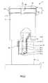
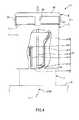
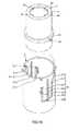
図1〜図7は、それぞれ、本発明の液体投与具の使用時の作動状態を順に示す側面図(一部を切欠いた図)、図8〜図14は、それぞれ、図1〜図7に示す状態の液体投与具の縦断面図、図15は、本発明の液体投与具が備える操作部材と規制部材との位置関係を示す分解斜視図、図16は、本発明の液体投与具が備える規制部材とカバー部材との位置関係を示す分解斜視図、図17は、本発明の液体投与具が備える規制部材を先端側から見た図、図18は、本発明の液体投与具が備える穿刺針を示す斜視図である。なお、以下では、説明の都合上、図1〜図16および図18中の上側を「基端」または「上(上方)」、下側を「先端」「下(下方)」と言う。Hereinafter, the liquid administration device of the present invention will be described in detail based on preferred embodiments shown in the accompanying drawings.
FIGS. 1 to 7 are side views (partially cutaway views) illustrating the operating states of the liquid administration device of the present invention in order, and FIGS. 8 to 14 are FIGS. FIG. 15 is an exploded perspective view showing the positional relationship between the operation member and the regulating member provided in the liquid administration device of the present invention, and FIG. 16 is provided in the liquid administration device of the present invention. 17 is an exploded perspective view showing the positional relationship between the regulating member and the cover member, FIG. 17 is a view of the regulating member provided in the liquid administration device of the present invention as viewed from the distal end side, and FIG. 18 is a puncture provided in the liquid administration device of the present invention. It is a perspective view which shows a needle | hook. In the following, for convenience of explanation, the upper side in FIGS. 1 to 16 and 18 is referred to as “base end” or “upper (upper)”, and the lower side is referred to as “tip” and “lower (lower)”.
図1〜図14に示す液体投与具10は、液体Qを生体Bに投与する(注入する)際に用いられる医療器具である。なお、液体Qとしては、その使用目的に応じて適宜選択されるが、例えば、造血剤、ワクチン、ホルモン製剤、抗リウマチ剤、抗ガン剤、麻酔剤、血液凝固防止剤等、主に皮下注射される薬液が挙げられる。 A
液体投与具10は、内筒(筒体)1と、両頭針2と支持部材9とで構成された穿刺針50と、内筒1内で摺動し得るガスケット3と、ガスケット3の基端側に連結された操作部材11と、操作部材11の作動を規制する規制部材4と、内筒1の外周側に配置されたカバー部材6と、カバー部材6を付勢する付勢手段としてのコイルバネ60とを備えている。 The
図8〜図14に示すように、内筒1は、先端部に底部12と、当該底部12の縁部から立設した側壁13とを有する部材、すなわち、有底筒状をなす部材で構成された内筒本体14を有している。そして、内筒1の内部には、液体Qが充填可能である。 As shown in FIGS. 8 to 14, the
底部12は、形状がすり鉢状をなし、その中心部に液体が通過する口部121が貫通して形成されている。 The
側壁13は、形状が円筒状をなしている。 The
また、内筒1は、内筒本体14の口部121を液密に封止する封止部材(封止部)15と、封止部材15をその先端側から固定する固定部材16とを有している。 Further, the
封止部材15は、円板状をなす弾性片で構成され、その基端面にリング状の凹部151が形成されている。この凹部151に、内筒本体14の口部121に突出形成されたリング状の凸部122が液密に嵌合することができる。これにより、封止部材15が内筒本体14の口部121に装着されるとともに、当該口部121を液密に封止することができる。 The sealing
固定部材16は、リング状をなす部材である。そして、この固定部材16は、封止部材15にその外周側から嵌合して、凸部122との間で封止部材15を挟持することにより、当該封止部材15を内筒本体14に対して確実に固定することができる。これにより、封止部材15の内筒本体14からの離脱が確実に防止される。なお、固定部材16の固定方法としては、その他、接着による方法や溶着による方法であってもよい。 The fixing
また、内筒本体14、固定部材16、カバー部材6、支持部材9、操作部材11、規制部材4の構成材料としては、特に限定されず、例えば、ポリ塩化ビニル、ポリエチレン、ポリプロピレン、環状ポリオレフィン、ポリスチレン、ポリ−(4−メチルペンテン−1)、ポリカーボネート、アクリル樹脂、アクリルニトリル−ブタジエン−スチレン共重合体、ポリエチレンテレフタレート、ポリエチレンナフタレート等のポリエステル、ブタジエン−スチレン共重合体、ポリアミド(例えば、ナイロン6、ナイロン6・6、ナイロン6・10、ナイロン12)のような各種樹脂が挙げられるが、その中でも、成形が容易であるという点で、ポリプロピレン、環状ポリオレフィン、ポリエステル、ポリ−(4−メチルペンテン−1)のような樹脂が好ましい。 Moreover, it does not specifically limit as a constituent material of the inner cylinder
また、封止部材15、ガスケット3を構成する弾性材料としては、特に限定されず、例えば、天然ゴム、ブチルゴム、イソプレンゴム、ブタジエンゴム、スチレン−ブタジエンゴム、シリコーンゴムのような各種ゴム材料や、ポリウレタン系、ポリエステル系、ポリアミド系、オレフィン系、スチレン系等の各種熱可塑性エラストマー、あるいはそれらの混合物等の弾性材料が挙げられる。 The elastic material constituting the sealing
内筒1の先端側には、穿刺針50が配置されている。穿刺針50は、両頭針2と支持部材9とで構成されている。 A
両頭針2は、中空の針管であり、先端に鋭利な先端側針先(針先)21を有し、基端にも鋭利な基端側針先23を有する。この両頭針2は、先端側針先21で生体Bを穿刺することができ、基端側針先23で内筒1の封止部材15を刺通することができる。 The double-ended
両頭針2の内腔部(中空部)は、基端側針先23が内筒1の封止部材15を刺通した状態で、内筒1と連通しており、内筒1からの液体Qが通過する流路22として機能する。そして、さらに先端側針先21で生体Bを皮膚から所定の深さまで穿刺した状態で、当該生体Bに流路22を介して液体Qが注入される。 The lumen portion (hollow portion) of the double-ended
なお、両頭針2の構成材料としては、特に限定されず、例えば、ステンレス鋼、アルミニウムまたはアルミニウム合金、チタンまたはチタン合金のような金属材料が挙げられる。 In addition, it does not specifically limit as a constituent material of the double-ended
このような構成の両頭針2は、支持部材9を介して内筒1に装着されている。支持部材9は、両頭針2を内筒1に対しその中心軸方向に沿って移動可能に支持するものである。この支持部材9は、円板状をなす固定部(支持部)91と、固定部91の縁部から基端方向に向かって立設した壁部92とで構成されている。 The double-ended
固定部91は、その中心部で両頭針2を支持、固定することができる。なお、両頭針2の固定部91で支持される箇所は、両頭針2の長手方向の途中である。 The fixing
壁部92は、固定部91の縁部に沿ったリング状をなす部分である。図18に示すように、壁部92の基端内周部には、内側に向かって突出した複数(図8に示す構成では4つ)の係合部921が形成されている。各係合部921は、それぞれ、壁部92の周方向に沿って等間隔に配置されている。各係合部921は、それぞれ、穿刺針50の内筒1に対する位置に応じて、当該内筒1の底部12の縁部に凹没して形成された第1の係合部123または第2の係合部124に係合することができる(図8、図9、図11〜図14参照)。そして、各係合部921が第1の係合部123に係合する状態、各係合部921が各係合部921に係合する状態のいずれの状態でも、穿刺針50が内筒1の先端部から離脱するのが防止される。 The
前述したように、穿刺針50は、支持部材9を介して内筒1に対しその中心軸方向に沿って移動可能に支持されている。これにより、穿刺針50は、基端側針先23が内筒1の封止部材15から離間した(または刺通仕切らない)図8〜図10に示す離間状態と、基端側針先23が封止部材15を刺通した図11〜図14に示す刺通状態とを取り得る。よって、刺通状態となるまで両頭針2からの液体Qの不本意な漏出が防止される。 As described above, the
なお、離間状態では、各係合部921が第1の係合部123に係合しており、刺通状態では、各係合部921が各係合部921に係合している。 Note that, in the separated state, each engaging
ガスケット3は、内筒1の軸方向に沿って摺動可能に収納されている。なお、このガスケット3と内筒1とで囲まれた空間には、液体Qが予め充填されている。そして、ガスケット3が先端方向に向かって移動することにより、内筒1内の液体Qを、当該内筒1に連通した状態の両頭針2から押し出すことができる。 The
このガスケット3は、外形形状が円盤状をなし、その外周部に2つの突部31、32が突出形成されている。突部31と突部32とは、ガスケット3の軸方向に沿って離間している。また、突部31、32は、それぞれ、ガスケット3の周方向に沿ったリング状をなし、その外径は、外力を付与しない自然状態で、内筒1の内径よりも若干大きい。これにより、突部31、32は、それぞれ、内筒1の側壁13の内周部133に対し密着しつつ摺動することができ、よって、液密性を確実に保持するとともに、摺動性の向上が図れる。 The
また、ガスケット3の基端面には、操作部材11のプランジャ82の先端部が挿入されて(嵌合して)連結する凹部33が開口している。 In addition, a
操作部材11は、ガスケット3を先端方向に向かって押圧して液体Qを両頭針2から吐出させる押圧操作(吐出操作)を行なう部材である。操作部材11は、ガスケット3と連結される操作部材本体8と、押圧操作を行なうときに把持される把持部材(把持部)7とを有している。 The
図15に示すように、操作部材本体8は、円板状をなす天板81と、天板81の下面に円柱状に突出形成されたプランジャ82とを有している。 As shown in FIG. 15, the operation member
天板81の縁部側には、当該天板81から先端方向に向かって形成された爪部83が複数配置されている。そして、円筒状をなす把持部材7の外周部71にその周方向に沿ってリング状に突出形成されたリブ711に各爪部83が係合することにより、操作部材本体8と把持部材7とが互いに固定されることとなる(図1〜図14参照)。そして、操作部材11を操作する際に、例えば片方の手の人差し指から小指までを把持部材7の外周部71に掛け、親指を操作部材本体8の天板81に掛けて、その操作を確実に行なうことができる。 On the edge side of the
図8〜図14に示すように、液体投与具10では、内筒1の外周側に円筒状をなす規制部材4が配置され、さらに、規制部材4の外周側に円筒状をなすカバー部材6が配置されている。これらの部材同士は、同心的に配置されている。また、規制部材4は、内筒1に対しその中心軸回りに回動可能に支持されており、カバー部材6は、内筒1に対しその中心軸方向に沿って移動可能に支持されている。 As shown in FIGS. 8 to 14, in the
カバー部材6は、第1の位置(図1、図2、図8、図9参照)と、第2の位置(図3〜図6および図10〜図13参照)と、第3の位置(図7および図14参照)とに移動することができる。第1の位置では、カバー部材6は、両頭針2の少なくとも先端側針先21を覆うことができる。これにより、先端側針先21による誤穿刺や、先端側針先21が損傷を受けるのを確実に防止することができる。また、この第1の位置から基端方向に移動した(退避した)第2の位置では、先端側針先21が露出する。これにより、先端側針先21で生体Bを穿刺することができる。また、第2の位置から先端方向に向かって移動した第3の位置では、両頭針2の少なくとも先端側針先21を再度覆うことができるとともに、第2の位置へ移動が阻止される。 The
このカバー部材6は、コイルバネ60の付勢力により、第2の位置から第1の位置(第3の位置)に移動する方向に向かって付勢されている。 The
図8〜図14に示すように、コイルバネ60は、圧縮状態でカバー部材6に収納されている。このコイルバネ60は、その先端601がカバー部材6のリング状の先端壁部63に当接し、基端602が内筒1のリブ43に当接している。そして、これらの間で、コイルバネ60が圧縮されている。これにより、カバー部材6を第2の位置から第1の位置へ向かう方向に確実に付勢することができる。このようなコイルバネ60の付勢力により、液体投与具10の使用前後で、穿刺針50の先端側針先21をカバー部材6で覆うことができ、よって、当該先端側針先21による誤穿刺等を確実に防止することができる。 As shown in FIGS. 8 to 14, the
なお、コイルバネ60の構成材料としては、特に限定されず、例えば、ステンレス鋼等のような金属材料を用いることができる。 In addition, it does not specifically limit as a constituent material of the
また、規制部材4は、操作部材11に対し、押圧操作規制状態(図8、図9参照)と、押圧操作可能状態(図11〜図13参照)とを取り得る。押圧操作規制状態は、カバー部材6が第1の位置にあるときに、操作部材11による押圧操作を規制することができる状態である。押圧操作可能状態は、カバー部材6が第1の位置から第2の位置に移動した際に、操作部材11による押圧操作を可能とする(許可する)状態である。 Further, the restricting
さらに、規制部材4は、カバー部材6に対し、第1の移動可能状態(図1〜図3参照)と、第2の移動可能状態(図6参照)と、移動規制状態(図7参照)とを取り得る。移動可能状態は、カバー部材6が第1の位置から第2の位置への移動するのを可能とする(許可する)状態である。第2の移動可能状態は、押圧操作の完了に連動して、カバー部材6が第2の位置から第3の位置へ移動するのを可能とする(許容する)状態である。移動規制状態は、カバー部材6が一旦第2の位置に退避して第3の位置に移動してから再度第2の位置へ移動するのを規制する状態である。 Furthermore, the regulating
以下、これらの状態を取るための構成について説明する。 Hereinafter, a configuration for taking these states will be described.
図15、図16に示すように、規制部材4(一方の部材)の内周部の基端部には、その周方向に沿ってリング状に形成されたリブ41が突出している。そして、このリブ41には、スライダ部となる、内側に向かって突出した内側突部(内側フォロア部)42が複数(本実施形態では4つ)形成されている。これらの内側突部42は、リブ41(規制部材4の内周部)の周方向に沿って等間隔に配置されている。 As shown in FIGS. 15 and 16, a
また、規制部材4の外周部には、その軸方向の途中に、当該外周部の周方向に沿ってリング状に形成されたリブ43が突出している。そして、このリブ43には、内側突部42よりも外側に位置する外側スライダ部となる、外側に向かって突出した外側突部(外側フォロア部)44が複数(本実施形態では2つ)形成されている。これらの外側突部44は、リブ43(規制部材4の外周部)の周方向に沿って等間隔に配置されている。 Further, a
図15に示すように、規制部材4の内側に規制部材4と同心的に配置されたプランジャ82(他方の部材)には、その外周部に、内側突部42が摺動する内側レール部(レール部)として、内側突部42と同数の内側溝部(内側カム溝)84が形成されている。これらの内側溝部84は、各内側突部42にそれぞれ対応するように複数配置されており、対応する1つの内側突部42が挿入される。 As shown in FIG. 15, the plunger 82 (the other member) arranged concentrically with the regulating
なお、内側突部42および内側溝部84の形成数は、1つでもよいが、本実施形態のように複数あるのが好ましい。これにより、規制部材4が安定して回動することができる。 Note that the number of the
各内側溝部84の構成は、それぞれ、同じであるため、1つの内側溝部84について代表的に説明する。 Since the configuration of each
内側溝部84は、内側縦溝(縦方向レール)841と、内側横溝(横方向レール)842と、内側傾斜溝843とで構成されている。 The
内側縦溝841は、操作部材11による押圧操作時の操作方向と同方向に向かって、すなわち、プランジャ82の軸方向(長手方向)に沿って形成されている。 The inner
内側横溝842は、押圧操作時の操作方向に対し垂直な方向に向かって、すなわち、プランジャ82の周方向に沿って形成されている。この内側横溝842は、内側縦溝841の長手方向の途中と交差して、すなわち、連通して(連続して)いる。 The inner
内側傾斜溝843は、プランジャ82の軸方向に対して傾斜した方向に沿って形成されている。この内側傾斜溝843は、その先端部が内側縦溝841の基端部と交差している。 The inner
また、隣接する内側溝部84の内側横溝842同士は、互いに連通しており、4つの内側溝部84の内側横溝842が全体としてリング状の溝を構成している。 The inner
図8、図9に示すように、カバー部材6が第1の位置にあるときには、内側突部42は、内側横溝842に位置している。これにより、操作部材11による押圧操作を規制する押圧操作規制状態となる。 As shown in FIGS. 8 and 9, when the
図11〜図13に示すように、カバー部材6がコイルバネ60の付勢力に抗して第1の位置から第2の位置に移動した際には、その移動に連動して、内側突部42は、内側横溝842から内側縦溝841に移動して、当該内側縦溝841(内側縦溝841と内側横溝842との交差部、内側縦溝841と内側傾斜溝843との交差部も含む)に位置する。これにより、操作部材11による押圧操作が可能となる押圧操作可能状態となる。なお、内側突部42の内側横溝842から内側縦溝841への移動は、規制部材4が回転することにより行なわれ、その回転力は、規制部材4の外側突部44が、後述するカバー部材6の外側溝部61を移動することにより生じる。 As shown in FIGS. 11 to 13, when the
図14に示すように、カバー部材6がコイルバネ60の付勢力により第2の位置から第1の位置に戻るまでは、内側突部42は、内側縦溝841から内側傾斜溝843に移動して、当該内側傾斜溝843を進む。なお、このときも、規制部材4は前記と同方向に回転することとなる。 As shown in FIG. 14, the
図16に示すように、カバー部材6には、外側突部44が摺動する外側レール部として、外側突部44と同数の外側溝部(外側カム溝)61が形成されている。これらの外側溝部61は、各外側突部44にそれぞれ対応するように複数配置されており、対応する1つの外側突部44が挿入される。 As shown in FIG. 16, the
なお、外側突部44および外側溝部61の形成数は、1つでもよいが、本実施形態のように複数あるのが好ましい。これにより、内側突部42および内側溝部84がそれぞれ複数形成されているのと相まって、規制部材4がより安定して回動することができる。 The number of the
各外側溝部61の構成は、それぞれ、同じであるため、1つの外側溝部61について代表的に説明する。 Since the configuration of each
外側溝部61は、第1の外側縦溝(第1の外側縦方向レール)611と、第2の外側縦溝(第2の外側縦方向レール)612と、第3の外側縦溝613と、第1の外側傾斜溝(外側傾斜レール)614と、第2の外側傾斜溝615と、外側横溝(外側横方向レール)616と、外側係合部617とで構成されている。なお、第1の外側縦溝611〜外側横溝616は、それぞれ、カバー部材6の内周部から外周部まで、すなわち、円筒状をなすカバー部材6の壁部を貫通した貫通孔である。 The
第1の外側縦溝611は、操作部材11による押圧操作時の操作方向と同方向に向かって、すなわち、プランジャ82の軸方向に沿って形成されている。 The first outer
第2の外側縦溝612は、第1の外側縦溝611に対してプランジャ82の周方向に沿って離間した位置に、押圧操作時の操作方向と反対方向に向かって、すなわち、第1の外側縦溝611と平行に形成されている。 The second outer
第3の外側縦溝613は、第1の外側縦溝611と第2の外側縦溝612との間に、押圧操作時の操作方向と反対方向に向かって形成されている。 The third outer
第1の外側傾斜溝614は、第1の外側縦溝611と第3の外側縦溝613との間に、押圧操作時の操作方向に対し傾斜した方向に沿って形成されている。この第1の外側傾斜溝614は、その先端部が第3の外側縦溝613の先端部と交差しており、基端部が第1の外側縦溝611の先端部と交差している。 The first outer
第2の外側傾斜溝615は、押圧操作時の操作方向に対し傾斜した方向に沿って形成され、その先端部が第1の外側縦溝611の基端部と交差している。 The second outer
外側横溝616は、第2の外側縦溝612と第3の外側縦溝613との間に、押圧操作時の操作方向に対し垂直な方向に沿って形成されている。この外側横溝616は、その一端部が第2の外側縦溝612に基端部と交差し、他端部が第3の外側縦溝613の先端部および第1の外側傾斜溝614の先端部と交差している。 The outer
外側係合部617は、第2の外側縦溝612を画成するカバー部材6の壁部の一部で構成された弾性片である。この外側係合部617は、第2の外側縦溝612の基端部に配置され、カバー部材6が第1の位置に戻った際に外側突部44にその先端側から係合することができる(図7参照)。また、弾性片で構成された外側係合部617は、弾性的に変形することができ、よって、カバー部材6が第2の位置から第3の位置へ移動する際に、外側突部44が外側係合部617を超えることができ、よって、その移動を許容することができる。 The outer
図1〜図3に示すように、外側突部44は、第2の外側傾斜溝615、第1の外側縦溝611、第1の外側傾斜溝614を順に移動することができる。これにより、カバー部材6が第1の位置から第2の位置に移動するのが可能な第1の移動可能状態となる。 As shown in FIGS. 1 to 3, the
また、外側突部44が第1の外側傾斜溝614を移動する際には、規制部材4が回転することができる。前述したように、この回転により、内側突部42が内側横溝842から内側縦溝841に移動することができ、よって、操作部材11による押圧操作が可能な押圧操作可能状態となる。 Further, when the
図4〜図6に示すように、カバー部材6が第2の位置にあるときには、外側突部44が外側横溝616を移動することができる。なお、この移動は、規制部材4が回転することにより行なわれ、その回転力は、内側突部42が内側傾斜溝843を移動することにより生じる。 As shown in FIGS. 4 to 6, when the
また、図6に示すように、外側突部44が外側横溝616を移動しきると、それに続いて、第2の外側縦溝612を移動することができる。これにより、カバー部材6が第2の位置から第3の位置へ移動するのが可能な第2の移動可能状態となる。 As shown in FIG. 6, when the
図7に示すように、カバー部材6が第2の位置から第1の位置に戻るときには、外側突部44が第2の外側縦溝612を移動する。そして、この外側突部44は、外側係合部617に係合することとなる。これにより、カバー部材6が再度第2の位置へ移動するが規制される移動規制状態となる。 As shown in FIG. 7, when the
また、外側溝部61は、前述したように貫通孔であり、外側突部44が露出することができる。図7に示すように、移動規制状態では、外側突部44と、外側突部44に係合した状態の外側係合部617とが、操作部材11の把持部材7で覆われる。これにより、外側突部44と外側係合部617との係合が不本意に解除されるのを確実に防止することができ、よって、カバー部材6が第1の位置に確実に留まることができる。このカバー部材6により、先端側針先21が覆われ、誤穿刺等を防止することができる。 Moreover, the outer
図8〜図14に示すように、穿刺針50は、内筒1に対しその軸方向に沿って移動することができる。そして、規制部材4は、カバー部材6が第1の位置にあるときに、穿刺針50(支持部材9)の移動を規制する穿刺針移動規制状態を取ることもできる。次に、この穿刺針移動規制状態を取るための構成について説明する。 As shown in FIGS. 8 to 14, the
図17に示すように、規制部材4の内周部の先端部には、内側に向かって突出した内側突部(第2の内側突部)45が複数(本実施形態では4つ)形成されている。これらの内側突部45は、規制部材4の周方向に沿って等間隔に配置されている。 As shown in FIG. 17, a plurality (four in the present embodiment) of inner protrusions (second inner protrusions) 45 projecting inward are formed at the tip of the inner peripheral portion of the regulating
図18に示すように、穿刺針50の支持部材9の壁部92の外周部には、内側突部45と同数の段差部922が形成されている。各段差部922は、それぞれ、壁部92の外周部に外側に向かった段差を生じさせるように形成されている。 As shown in FIG. 18, the same number of
カバー部材6が第1の位置にあるときには、各段差部922に、それぞれ、その基端側から内側突部45が係合する(図18中の実線で示す「内側突部45」参照)。これにより、穿刺針50の移動が規制される穿刺針移動規制状態となり、よって、液体投与具10の使用前に不本意に両頭針2が内筒1の封止部材15を刺通するのが防止され、両頭針2からの液体Qの漏れが防止される。 When the
そして、穿刺針移動規制状態から、前述したように規制部材4が回転することにより、各段差部922から内側突部45が外れて(図18中の二点鎖線で示す「内側突部45」参照)、穿刺針移動規制状態が解除される。これにより、穿刺針50が基端側に移動可能な状態となり、よって、両頭針2が内筒1の封止部材15を刺通することができる。 Then, when the restricting
次に、液体投与具10の使用方法と、その使用時の作動状態とについて、図1〜図14を参照しつつ説明する。 Next, a method for using the
[1] 図1、図8に示す未使用状態(初期状態)の液体投与具10を用意する。この未使用状態の液体投与具10では、カバー部材6は、第1の位置にあり、両頭針2の先端側針先21を覆っている。なお、この未使用状態では、コイルバネ60の付勢力により、カバー部材6で先端側針先21が覆われた状態が維持されている。これにより、先端側針先21による誤穿刺を確実に防止することができる。 [1] A
また、図8に示すように、穿刺針50は、両頭針2の基端側針先23が内筒1の封止部材15から離間しており、封止部材15を未だ刺通していない。この基端側針先23が内筒1の封止部材15から離間した状態は、穿刺針移動規制状態の規制部材4によって確実に維持されている。これにより、薬液Qの投与が開始されるまで、液体Qの無菌状態を維持することができる。 Further, as shown in FIG. 8, the
また、規制部材4は、各内側突部42がそれぞれ操作部材11のプランジャ82の内側横溝842に位置しており、操作部材11に対して押圧操作規制状態となっている。これにより、操作部材11による押圧操作が規制される(不能となる)。 Further, in the restricting
さらに、規制部材4は、各外側突部44がそれぞれ第2の外側傾斜溝615に位置しており、カバー部材6に対して移動可能状態となっている。 Further, the restricting
[2] 次に、未使用状態の液体投与具10の操作部材11の把持部材7を把持して、図2、図9に示すように、カバー部材6の先端壁部63を生体Bに当接させ、そのまま、操作部材11を先端方向に向かって押圧する。これにより、カバー部材6は、コイルバネ60の付勢力に抗して、第1の位置から第2の位置へ移動し始める。また、その移動過程では、各外側突部44がそれぞれ第2の外側傾斜溝615を進む。これにより、規制部材4が回転して、穿刺針移動規制状態が解除され、よって、穿刺針50が基端側に移動可能な状態となる。 [2] Next, the grasping member 7 of the
[3] 図2に示す状態から操作部材11をさらに先端方向に向かって押圧すると、各外側突部44がそれぞれ第1の外側縦溝611を進むこととなり(図3参照)、カバー部材6が穿刺防止位置から穿刺可能位置へ移動する。このとき、両頭針2の先端側針先21が、カバー部材6の先端壁部63の開口部631から突出して、先端側針先21での生体Bに対する穿刺が行なわれる(図3、図10参照)。 [3] When the
また、カバー部材6の移動とともに、当該カバー部材6の先端壁部63が穿刺針50の支持部材9を基端方向に向かって押圧し始める(図10参照)。 As the
[4] 図3に示す状態から操作部材11を先端方向に向かって押圧し続けると、各外側突部44がそれぞれ第1の外側傾斜溝614を進む(図4参照)。これにより、規制部材4が回転して、内側突部42が内側縦溝841まで移動することとなり、押圧操作可能状態となる(図11参照)。 [4] When the operating
また、このとき、カバー部材6の先端壁部63が穿刺針50の支持部材9を基端方向に向かってさらに押圧する。これにより、両頭針2の基端側針先23で、内筒1の封止部材15を刺通することができ、よって、生体Bを穿刺した両頭針2と、内筒1とが連通する(図11参照)。 At this time, the
[5] さらに、図4、図11に示す状態から操作部材11を先端方向に向かって押圧し続けると、内側突部42が内側縦溝841、内側傾斜溝843を順に進むこととなり、ガスケット3が内筒1の底部12に当接する移動限界まで移動して、液体Qを両頭針2から排出することができる(図12、図13参照)。これにより、液体Qの投与が完了する。 [5] Further, when the operating
なお、内側突部42が内側傾斜溝843を進むことにより、規制部材4が回転する。これにより、外側突部44が外側横溝616を進んで、第2の外側縦溝612に至る(図5、図6参照)。 In addition, when the
[6] 次に、図7、図14に示すように、液体投与具10を生体Bから離間させる。これにより、カバー部材6は、コイルバネ60の付勢力により先端方向に向かって付勢されることとなり、外側突部44が第2の外側縦溝612を進み、第1の位置に戻る。 [6] Next, as shown in FIGS. 7 and 14, the
このとき、規制部材4は、外側突部44が外側係合部617に係合することができ、よって、カバー部材6に対して移動規制状態となる。これにより、カバー部材6が再度第2の位置へ移動するのが確実に規制され、先端側針先21による誤穿刺が防止される。 At this time, the restricting
このように、液体投与具10では、生体Bに対する穿刺が行なわれてから、液体Qの投与が行なわれる。すなわち、液体投与具10では、「穿刺」、「投与」の順番で確実に使用することができる。従って、生体Bに対する穿刺が行われる前に、操作部材11によって液体Qを吐出させる押圧操作が誤って行なわれるのを確実に防止することができる。 Thus, in the
なお、液体投与具10では、液体Qの投与中に、その投与を停止することができる。この場合、液体投与具10を生体Bから離間させれば、カバー部材6は、コイルバネ60の付勢力により先端方向に向かって付勢されることとなり、外側突部44が第3の外側縦溝613を進み、第1の位置に戻ることができる。 In addition, in the
以上、本発明の液体投与具を図示の実施形態について説明したが、本発明は、これに限定されるものではなく、液体投与具を構成する各部は、同様の機能を発揮し得る任意の構成のものと置換することができる。また、任意の構成物が付加されていてもよい。 The liquid administration device of the present invention has been described above with respect to the illustrated embodiment. However, the present invention is not limited to this, and each component constituting the liquid administration device can have any function that can exhibit the same function. Can be substituted. Moreover, arbitrary components may be added.
また、穿刺針は、前記実施形態では両頭針である針管を有するものであるが、これに限定されず、基端側針先が省略された針管を有するものであってもよい。この場合、針管は、予め(未使用状態で既に)内筒と連通している。 Moreover, although the puncture needle has a needle tube which is a double-ended needle in the embodiment, the puncture needle is not limited to this, and may have a needle tube from which the proximal needle tip is omitted. In this case, the needle tube communicates with the inner cylinder in advance (already in an unused state).
また、前記実施形態では、内側突部が操作部材および規制部材のうちの規制部材に形成され、内側突部が挿入される内側溝部が操作部材のプランジャに形成されている。本願発明では、これに限定されず、内側突部が操作部材のプランジャに形成され、内側溝部が規制部材に形成されていてもよい。 Moreover, in the said embodiment, the inner side protrusion is formed in the control member of an operation member and a control member, and the inner side groove part in which an inner side protrusion is inserted is formed in the plunger of the operation member. In this invention, it is not limited to this, An inner side protrusion part may be formed in the plunger of an operation member, and the inner side groove part may be formed in the control member.
前記実施形態では、外側突部が規制部材およびカバー部材のうちの規制部材に形成され、外側突部が挿入される外側溝部がカバー部材に形成されている。本願発明では、これに限定されず、外側突部がカバー部材に形成され、外側溝部が規制部材に形成されていてもよい。 In the embodiment, the outer protrusion is formed on the restriction member of the restriction member and the cover member, and the outer groove portion into which the outer protrusion is inserted is formed on the cover member. In this invention, it is not limited to this, An outer side protrusion part may be formed in a cover member, and the outer side groove part may be formed in the control member.
また、外側溝部では、第3の外側縦溝を省略することができる。 In the outer groove portion, the third outer longitudinal groove can be omitted.
また、前記実施形態では、規制部材は円筒状をなすものとして説明したが、円筒の高さ方向が短く、実質的に中心に孔を有する円盤状(ドーナツ形状)であってもよく、本願明細書の規制部材の説明における「円筒状」の概念には円盤状のものも含まれるものとする。 In the above-described embodiment, the restriction member has been described as having a cylindrical shape, but the height direction of the cylinder may be short, and may be a disk shape (doughnut shape) having a hole substantially in the center. It is assumed that the “cylindrical” concept in the description of the restricting member of the book includes a disk shape.
また、外側レール部および内側レール部は、それぞれ、前記実施形態では溝で構成されているが、外側スライダ部および内側スライダ部がレールに沿って滑動可能であればこれに限定されず、例えば、外側レール部および内側レール部がそれぞれ凸条(リブ)や段差で構成されていてもよい。 In addition, the outer rail portion and the inner rail portion are each configured with a groove in the above embodiment, but the outer slider portion and the inner slider portion are not limited to this as long as the outer slider portion and the inner slider portion can slide along the rail. The outer rail portion and the inner rail portion may each be constituted by a ridge (rib) or a step.
本発明の液体投与具は、筒状をなし、その内側に液体が充填された筒体と、先端および基端のうちの少なくとも先端に鋭利な先端側針先を有し、前記筒体の先端側に設けられ、該筒体と連通可能な針管と、前記筒体内で摺動し得るガスケットと、前記ガスケットの基端側に連結され、該ガスケットを先端方向に向かって押圧して前記液体を前記針管から吐出させる押圧操作を行なう操作部材と、前記筒体の外周側に配置され、前記押圧操作を規制可能な規制部材と、前記針管の少なくとも前記先端側針先を覆う第1の位置と、該第1の位置から基端方向に退避して、前記先端側針先が露出する第2の位置とに移動可能なカバー部材とを備え、前記操作部材および前記規制部材のうちの一方の部材には、内側突部が突出形成され、他方の部材には、前記内側突部が挿入される内側溝部が形成されており、該内側溝部は、前記押圧操作時の操作方向と同方向に形成された内側縦溝と、該内側縦溝に連通し、前記操作方向に対し垂直な方向に形成された内側横溝とを有し、前記カバー部材が前記第1の位置にあるときに、前記内側突部が前記内側横溝に位置して、前記押圧操作を規制し、前記カバー部材が前記第1の位置から前記第2の位置に移動した際、その移動に連動して前記内側突部が前記内側横溝から前記内側縦溝に移動し、これにより、前記押圧操作が可能となる。そのため、操作部材の作動を規制したいときに、操作部材が誤って作動するのを確実に防止することができる。また、カバー部材が第1の位置から第2の位置になるまで確実に操作部材の移動が規制されるため、この間に筒体中の液体の内圧が上昇するのを防止することができる。 The liquid administration device of the present invention has a cylindrical shape, a cylindrical body filled with liquid, and a sharp distal needle tip at least at the distal end and the proximal end, and the distal end of the tubular body A needle tube that can communicate with the cylindrical body, a gasket that can slide within the cylindrical body, and a proximal end side of the gasket, and press the gasket toward the distal direction to discharge the liquid. An operation member that performs a pressing operation to be discharged from the needle tube, a regulating member that is disposed on an outer peripheral side of the cylindrical body and that can regulate the pressing operation, and a first position that covers at least the tip side needle tip of the needle tube; A cover member that is retracted from the first position in the proximal direction and is movable to a second position where the distal needle tip is exposed, and one of the operating member and the regulating member The member has an inner protrusion that protrudes and the other member An inner groove portion into which the inner protrusion is inserted is formed, the inner groove portion communicates with the inner longitudinal groove formed in the same direction as the operation direction during the pressing operation, and the inner longitudinal groove, An inner lateral groove formed in a direction perpendicular to the operation direction, and when the cover member is in the first position, the inner protrusion is located in the inner lateral groove to restrict the pressing operation. When the cover member moves from the first position to the second position, the inner protrusion moves from the inner lateral groove to the inner vertical groove in conjunction with the movement, whereby the pressing member Operation becomes possible. Therefore, when it is desired to regulate the operation of the operation member, it is possible to reliably prevent the operation member from operating erroneously. Further, since the movement of the operation member is surely restricted until the cover member changes from the first position to the second position, it is possible to prevent the internal pressure of the liquid in the cylinder from increasing during this time.
従って、本発明の液体投与具は、産業上の利用可能性を有する。 Therefore, the liquid administration device of the present invention has industrial applicability.
10 液体投与具
1 内筒(筒体)
12 底部
121 口部
122 凸部
123 第1の係合部
124 第2の係合部
13 側壁
133 内周部
14 内筒本体
15 封止部材(封止部)
151 凹部
16 固定部材
2 両頭針
21 先端側針先(針先)
22 流路
23 基端側針先
3 ガスケット
31、32 突部
33 凹部
4 規制部材
41 リブ
42 内側突部(内側フォロア部)
43 リブ
44 外側突部(外側フォロア部)
45 内側突部(第2の内側突部)
6 カバー部材
61 外側溝部(外側カム溝)
611 第1の外側縦溝(第1の外側縦方向レール)
612 第2の外側縦溝(第2の外側縦方向レール)
613 第3の外側縦溝
614 第1の外側傾斜溝(外側傾斜レール)
615 第2の外側傾斜溝
616 外側横溝(外側横方向レール)
617 外側係合部
63 先端壁部
631 開口部
7 把持部材(把持部)
71 外周部
711 リブ
8 操作部材本体
81 天板
82 プランジャ
83 爪部
84 内側溝部(内側カム溝)
841 内側縦溝(縦方向レール)
842 内側横溝(横方向レール)
843 内側傾斜溝
9 支持部材
91 固定部(支持部)
92 壁部
921 係合部
922 段差部
11 操作部材
50 穿刺針
60 コイルバネ
601 先端
602 基端
B 生体
Q 液体10
12
151
22
43
45 Inner protrusion (second inner protrusion)
6 Cover
611 First outer longitudinal groove (first outer longitudinal rail)
612 Second outer longitudinal groove (second outer longitudinal rail)
613 Third outer
615 Second outer
617
71
841 Inner vertical groove (longitudinal rail)
842 Inner lateral groove (lateral rail)
843 Inner
92
Claims (7)
Translated fromJapanese前記筒体の先端側に、該筒体と連通して、もしくは連通可能に設けられた、先端に鋭利な針先を有する針管と、
前記筒体内で摺動し得るガスケットと、
前記ガスケットを先端方向に向かって押圧して前記液体を前記針管から吐出させる押圧操作を行なう操作部材と、
前記筒体の外周側に配置され、前記押圧操作を規制可能な規制部材と、
前記針管の少なくとも前記針先を覆う第1の位置と、該第1の位置から基端方向に退避して、前記針先が露出する第2の位置とに移動可能なカバー部材とを備え、
前記操作部材および前記規制部材のうちの一方の部材には、スライダ部が設けられ、他方の部材には、前記スライダ部が摺動するレール部が設けられており、該レール部は、前記押圧操作時の操作方向と同方向に形成された縦方向レールと、該縦方向レールに連続し、前記操作方向に対し垂直な方向に形成された横方向レールとを有し、
前記カバー部材が前記第1の位置にあるときに、前記スライダ部が前記横方向レールに位置して、前記押圧操作を不能とし、
前記カバー部材が前記第1の位置から前記第2の位置に移動した際、その移動に連動して前記スライダ部が前記横方向レールから前記縦方向レールに移動し、これにより、前記押圧操作が可能となることを特徴とする液体投与具。A cylindrical body that has a cylindrical shape and is filled with liquid;
A needle tube having a sharp needle tip at the tip, provided on the tip side of the tube, in communication with the cylinder, or provided to be able to communicate with the tube,
A gasket that can slide in the cylinder;
An operation member that performs a pressing operation of pressing the gasket toward the distal direction to discharge the liquid from the needle tube;
A regulating member that is arranged on the outer peripheral side of the cylindrical body and that can regulate the pressing operation;
A first member that covers at least the needle tip of the needle tube, and a cover member that is movable in a proximal direction from the first position to the second position where the needle tip is exposed.
One member of the operation member and the regulating member is provided with a slider portion, and the other member is provided with a rail portion on which the slider portion slides. A vertical rail formed in the same direction as the operation direction at the time of operation, and a horizontal rail continuous to the vertical rail and formed in a direction perpendicular to the operation direction,
When the cover member is in the first position, the slider portion is positioned on the lateral rail, and the pressing operation is disabled.
When the cover member moves from the first position to the second position, the slider portion moves from the horizontal rail to the vertical rail in conjunction with the movement, whereby the pressing operation is performed. A liquid administration device characterized by being made possible.
前記操作部材は、前記規制部材の内側に該規制部材と同心的に配置された柱状をなすプランジャを有し、
前記スライダ部は、前記規制部材の内周部にその周方向に沿って配置され、前記レール部は、前記プランジャの外周部に前記各スライダ部にそれぞれ対応するように配置されている請求項1に記載の液体投与具。The restriction member has a cylindrical shape,
The operating member has a plunger having a columnar shape arranged concentrically with the regulating member inside the regulating member,
2. The slider portion is disposed along an inner circumferential portion of the restricting member along a circumferential direction thereof, and the rail portion is disposed on an outer circumferential portion of the plunger so as to correspond to each slider portion. A liquid administration device according to 1.
前記カバー部材は、前記規制部材の外側に該規制部材と同心的に配置された円筒状をなすものであり、
前記規制部材の外周部および前記カバー部材の内周部のうちの一方には、前記スライダ部よりも外側に位置する外側スライダ部が設けられ、他方には、前記外側スライダ部が摺動する外側レール部が設けられており、該外側レール部は、前記操作方向に対し傾斜した方向に形成された外側傾斜レールを有し、
前記カバー部材が前記第1の位置から前記第2の位置に移動する過程で、前記外側スライダ部が前記外側傾斜レールを摺動することにより、前記規制部材がその軸回りに回転して、前記スライダ部が前記横方向レールから前記縦方向レールを摺動し、これにより、前記押圧操作が可能となる請求項1または2に記載の液体投与具。The restriction member has a cylindrical shape,
The cover member has a cylindrical shape arranged concentrically with the regulating member on the outside of the regulating member,
Outside the one of the inner periphery of the outer peripheral portion and the cover member of the regulating member, the outer slider part is provided which is located outside thesaid slider portion to the other, where the outer slider is slid A rail portion is provided, the outer rail portion having an outer inclined rail formed in a direction inclined with respect to the operation direction;
In the process in which the cover member moves from the first position to the second position, the outer slider portion slides on the outer inclined rail, whereby the regulating member rotates about its axis, The liquid administration device according to claim 1 or 2, wherein a slider portion slides on the vertical rail from the horizontal rail, thereby enabling the pressing operation.
前記規制部材は、前記押圧操作の完了に連動して、前記カバー部材の前記第2の位置から前記第3の位置への移動を許容するよう構成された請求項1または2に記載の液体投与具。The cover member is further movable to a third position that covers the needle tip and is prevented from moving to the second position;
The liquid administration according toclaim 1 , wherein the restricting member is configured to allow movement of the cover member from the second position to the third position in conjunction with completion of the pressing operation. Ingredients.
前記カバー部材は、前記規制部材の外側に該規制部材と同心的に配置された円筒状をなすものであり、
前記規制部材の外周部および前記カバー部材の内周部のうちの一方には、前記スライダ部よりも外側に位置する外側スライダ部が設けられ、他方には、前記外側スライダ部が摺動する外側レール部が設けられており、該外側レール部は、前記操作方向に対し傾斜した方向に形成された外側傾斜レールを有し、
前記外側レール部は、前記外側傾斜レールの基端部に連続し、前記押圧操作時の操作方向と同方向に形成された第1の外側縦方向レールと、前記外側傾斜レールの先端部に連続し、前記操作方向に対し垂直な方向に形成された外側横方向レールと、該外側横方向レールに連続し、前記押圧操作時の操作方向と反対方向に形成された第2の外側縦方向レールとを有し、
前記カバー部材が前記第1の位置から前記第2の位置に移動する過程では、前記外側スライダ部が前記第1の外側縦方向レール、前記外側傾斜レールを順に摺動し、前記カバー部材が前記第2の位置にあるときには、前記外側スライダ部が前記外側横方向レールを摺動し、前記カバー部材が前記第2の位置から前記第3の位置に移動するときには、前記外側スライダ部が前記第2の外側縦方向レールを移動する請求項4に記載の液体投与具。The restriction member has a cylindrical shape,
The cover member has a cylindrical shape arranged concentrically with the regulating member on the outside of the regulating member,
One of the outer peripheral part of the regulating member and the inner peripheral part of the cover member is provided with an outer slider part positioned outside the slider part, and the other is an outer side on which the outer slider part slides. A rail portion is provided, the outer rail portion having an outer inclined rail formed in a direction inclined with respect to the operation direction;
The outer rail portion is continuous with a base end portion of the outer inclined rail, and is continuous with a first outer longitudinal rail formed in the same direction as the operation direction during the pressing operation, and a distal end portion of the outer inclined rail. And an outer lateral rail formed in a direction perpendicular to the operation direction, and a second outer longitudinal rail formed in a direction opposite to the operation direction at the time of the pressing operation, which is continuous with the outer lateral rail. And
In the process in which the cover member moves from the first position to the second position, the outer slider portion slides on the first outer vertical rail and the outer inclined rail in order, and the cover member when in the second position, the outer slider is slid to the outer lateral rails, when the cover member is moved to the third position from the second position, the outer slider part isthe first 5. A liquid dosing device according to claim 4, which moves on two outer longitudinal rails.
Applications Claiming Priority (1)
| Application Number | Priority Date | Filing Date | Title |
|---|---|---|---|
| PCT/JP2012/068367WO2014013594A1 (en) | 2012-07-19 | 2012-07-19 | Liquid-administering instrument |
Publications (2)
| Publication Number | Publication Date |
|---|---|
| JP5865498B2true JP5865498B2 (en) | 2016-02-17 |
| JPWO2014013594A1 JPWO2014013594A1 (en) | 2016-06-30 |
Family
ID=49948448
Family Applications (1)
| Application Number | Title | Priority Date | Filing Date |
|---|---|---|---|
| JP2014525626AActiveJP5865498B2 (en) | 2012-07-19 | 2012-07-19 | Liquid dosing device |
Country Status (5)
| Country | Link |
|---|---|
| US (1) | US20150119815A1 (en) |
| EP (1) | EP2875838B1 (en) |
| JP (1) | JP5865498B2 (en) |
| CN (1) | CN104470562B (en) |
| WO (1) | WO2014013594A1 (en) |
Families Citing this family (16)
| Publication number | Priority date | Publication date | Assignee | Title |
|---|---|---|---|---|
| JP6104747B2 (en)* | 2013-07-25 | 2017-03-29 | テルモ株式会社 | Liquid dosing device |
| JP6296840B2 (en) | 2014-03-11 | 2018-03-20 | テルモ株式会社 | Liquid dosing device |
| JP6262030B2 (en)* | 2014-03-11 | 2018-01-17 | テルモ株式会社 | Liquid dosing device |
| JP6262031B2 (en)* | 2014-03-11 | 2018-01-17 | テルモ株式会社 | Liquid dosing device |
| EP3380147B1 (en)* | 2015-11-27 | 2025-02-19 | Sanofi-Aventis Deutschland GmbH | Medicament injection device |
| EP3380164A1 (en) | 2015-11-27 | 2018-10-03 | Sanofi-Aventis Deutschland GmbH | Medicament injection device |
| US11419992B2 (en) | 2015-11-27 | 2022-08-23 | Sanofi-Aventis Deutschland Gmbh | Medicament injection device |
| JP6937754B2 (en)* | 2015-11-27 | 2021-09-22 | サノフィ−アベンティス・ドイチュラント・ゲゼルシャフト・ミット・ベシュレンクテル・ハフツング | Drug delivery device |
| JP6617203B2 (en)* | 2016-03-16 | 2019-12-11 | イーライ リリー アンド カンパニー | Trigger assembly for automatic drug injection device |
| CN109152883B (en)* | 2016-05-18 | 2020-12-01 | 艾斯曲尔医疗公司 | Drug delivery mechanism for drug delivery devices |
| JP7246318B2 (en) | 2016-12-15 | 2023-03-27 | ピーケイエイ ソフトタッチ コーポレイション | Intradermal drug delivery device with locked post-dispensing configuration |
| EP4037734A1 (en)* | 2019-09-30 | 2022-08-10 | Amgen Inc. | Drug delivery device |
| EP4194032A4 (en)* | 2020-08-05 | 2024-09-11 | Lightnix, Inc. | Medical dosing device |
| JP2024501680A (en)* | 2020-12-24 | 2024-01-15 | エスエイチエル・メディカル・アーゲー | drug delivery device |
| EP4469111A1 (en)* | 2022-01-25 | 2024-12-04 | Regeneron Pharmaceuticals, Inc. | Drug delivery device safety system |
| CN117281978A (en)* | 2023-07-28 | 2023-12-26 | 梵颖(上海)生物科技有限公司 | Syringe protection device and safety syringe |
Citations (4)
| Publication number | Priority date | Publication date | Assignee | Title |
|---|---|---|---|---|
| JP2004049726A (en)* | 2002-07-23 | 2004-02-19 | Shimizu Pharmaceutical Co Ltd | Syringe |
| WO2009013844A1 (en)* | 2007-07-23 | 2009-01-29 | Terumo Kabushiki Kaisha | Drug solution injector |
| JP2009095392A (en)* | 2007-10-13 | 2009-05-07 | Iwaki:Kk | Injection needle and syringe using the same |
| WO2012000838A2 (en)* | 2010-07-02 | 2012-01-05 | Sanofi-Aventis Deutschland Gmbh | Safety device for a pre-filled syringe and injection device |
Family Cites Families (9)
| Publication number | Priority date | Publication date | Assignee | Title |
|---|---|---|---|---|
| JP4339260B2 (en)* | 2002-11-25 | 2009-10-07 | テクファーマ・ライセンシング・アクチェンゲゼルシャフト | Injection device with needle protection device |
| US20050101919A1 (en)* | 2003-11-07 | 2005-05-12 | Lennart Brunnberg | Device for an injector |
| JP2005319118A (en) | 2004-05-10 | 2005-11-17 | Terumo Corp | Method of manufacturing cap and prefilled syringe |
| WO2009040602A1 (en)* | 2007-09-25 | 2009-04-02 | Becton Dickinson France | Autoinject0r with deactivating means moveable by a safety shield |
| JP5432151B2 (en)* | 2007-09-25 | 2014-03-05 | ベクトン・ディキンソン・フランス・エス.エー.エス. | Automatic syringe housed in external socket |
| JP5732039B2 (en)* | 2009-03-20 | 2015-06-10 | アンタレス・ファーマ・インコーポレーテッド | Hazardous drug injection system |
| EP2424599B1 (en)* | 2009-04-27 | 2020-07-15 | SHL Medical AG | Safety pen needle device |
| US9155838B2 (en)* | 2010-02-05 | 2015-10-13 | Sanofi-Aventis Deutschland Gmbh | Medicated module having a double needle guard |
| US8496619B2 (en)* | 2011-07-15 | 2013-07-30 | Antares Pharma, Inc. | Injection device with cammed ram assembly |
- 2012
- 2012-07-19JPJP2014525626Apatent/JP5865498B2/enactiveActive
- 2012-07-19EPEP12881488.6Apatent/EP2875838B1/enactiveActive
- 2012-07-19CNCN201280074765.9Apatent/CN104470562B/enactiveActive
- 2012-07-19WOPCT/JP2012/068367patent/WO2014013594A1/enactiveApplication Filing
- 2015
- 2015-01-09USUS14/593,090patent/US20150119815A1/ennot_activeAbandoned
Patent Citations (4)
| Publication number | Priority date | Publication date | Assignee | Title |
|---|---|---|---|---|
| JP2004049726A (en)* | 2002-07-23 | 2004-02-19 | Shimizu Pharmaceutical Co Ltd | Syringe |
| WO2009013844A1 (en)* | 2007-07-23 | 2009-01-29 | Terumo Kabushiki Kaisha | Drug solution injector |
| JP2009095392A (en)* | 2007-10-13 | 2009-05-07 | Iwaki:Kk | Injection needle and syringe using the same |
| WO2012000838A2 (en)* | 2010-07-02 | 2012-01-05 | Sanofi-Aventis Deutschland Gmbh | Safety device for a pre-filled syringe and injection device |
Also Published As
| Publication number | Publication date |
|---|---|
| EP2875838A4 (en) | 2016-03-30 |
| US20150119815A1 (en) | 2015-04-30 |
| JPWO2014013594A1 (en) | 2016-06-30 |
| CN104470562B (en) | 2017-04-12 |
| WO2014013594A1 (en) | 2014-01-23 |
| EP2875838A1 (en) | 2015-05-27 |
| EP2875838B1 (en) | 2017-04-19 |
| CN104470562A (en) | 2015-03-25 |
Similar Documents
| Publication | Publication Date | Title |
|---|---|---|
| JP5865498B2 (en) | Liquid dosing device | |
| JP6731909B2 (en) | Packaging and packaging assembly | |
| JP5670242B2 (en) | Drug preparation tool | |
| WO2014112426A1 (en) | Liquid dispenser | |
| JP2011062527A (en) | Outer cover of pen type needle for drug supplying pen | |
| WO2014162551A1 (en) | Syringe | |
| WO2014115241A1 (en) | Liquid dispenser | |
| JP6046721B2 (en) | Liquid dosing device | |
| JP6068467B2 (en) | Pharmaceutical container | |
| JP6360470B2 (en) | Liquid dosing device | |
| JP6125187B2 (en) | Liquid dosing device | |
| JP6104747B2 (en) | Liquid dosing device | |
| JP6215550B2 (en) | Liquid dosing device | |
| JP6178306B2 (en) | Liquid dosing device | |
| WO2014013547A1 (en) | Liquid-administering instrument | |
| WO2013146049A1 (en) | Liquid administration device | |
| JP6342907B2 (en) | Liquid dosing device | |
| JP5897125B2 (en) | Liquid dosing device | |
| JP6165131B2 (en) | Liquid dosing device | |
| JP2005211336A (en) | Liquid guide appliance storage body |
Legal Events
| Date | Code | Title | Description |
|---|---|---|---|
| TRDD | Decision of grant or rejection written | ||
| A01 | Written decision to grant a patent or to grant a registration (utility model) | Free format text:JAPANESE INTERMEDIATE CODE: A01 Effective date:20151201 | |
| A61 | First payment of annual fees (during grant procedure) | Free format text:JAPANESE INTERMEDIATE CODE: A61 Effective date:20151225 | |
| R150 | Certificate of patent or registration of utility model | Ref document number:5865498 Country of ref document:JP Free format text:JAPANESE INTERMEDIATE CODE: R150 | |
| R250 | Receipt of annual fees | Free format text:JAPANESE INTERMEDIATE CODE: R250 | |
| R250 | Receipt of annual fees | Free format text:JAPANESE INTERMEDIATE CODE: R250 | |
| R250 | Receipt of annual fees | Free format text:JAPANESE INTERMEDIATE CODE: R250 | |
| R250 | Receipt of annual fees | Free format text:JAPANESE INTERMEDIATE CODE: R250 | |
| R250 | Receipt of annual fees | Free format text:JAPANESE INTERMEDIATE CODE: R250 | |
| R250 | Receipt of annual fees | Free format text:JAPANESE INTERMEDIATE CODE: R250 | |
| R250 | Receipt of annual fees | Free format text:JAPANESE INTERMEDIATE CODE: R250 |