JP5865356B2 - Diesel particulate filter - Google Patents
Diesel particulate filterDownload PDFInfo
- Publication number
- JP5865356B2 JP5865356B2JP2013512999AJP2013512999AJP5865356B2JP 5865356 B2JP5865356 B2JP 5865356B2JP 2013512999 AJP2013512999 AJP 2013512999AJP 2013512999 AJP2013512999 AJP 2013512999AJP 5865356 B2JP5865356 B2JP 5865356B2
- Authority
- JP
- Japan
- Prior art keywords
- filter
- catalyst
- exhaust gas
- zeolite
- group
- Prior art date
- Legal status (The legal status is an assumption and is not a legal conclusion. Google has not performed a legal analysis and makes no representation as to the accuracy of the status listed.)
- Active
Links
Images


Classifications
- B—PERFORMING OPERATIONS; TRANSPORTING
- B01—PHYSICAL OR CHEMICAL PROCESSES OR APPARATUS IN GENERAL
- B01J—CHEMICAL OR PHYSICAL PROCESSES, e.g. CATALYSIS OR COLLOID CHEMISTRY; THEIR RELEVANT APPARATUS
- B01J29/00—Catalysts comprising molecular sieves
- B01J29/04—Catalysts comprising molecular sieves having base-exchange properties, e.g. crystalline zeolites
- B01J29/06—Crystalline aluminosilicate zeolites; Isomorphous compounds thereof
- B01J29/40—Crystalline aluminosilicate zeolites; Isomorphous compounds thereof of the pentasil type, e.g. types ZSM-5, ZSM-8 or ZSM-11, as exemplified by patent documents US3702886, GB1334243 and US3709979, respectively
- B01J29/42—Crystalline aluminosilicate zeolites; Isomorphous compounds thereof of the pentasil type, e.g. types ZSM-5, ZSM-8 or ZSM-11, as exemplified by patent documents US3702886, GB1334243 and US3709979, respectively containing iron group metals, noble metals or copper
- B01J29/44—Noble metals
- B—PERFORMING OPERATIONS; TRANSPORTING
- B01—PHYSICAL OR CHEMICAL PROCESSES OR APPARATUS IN GENERAL
- B01D—SEPARATION
- B01D39/00—Filtering material for liquid or gaseous fluids
- B01D39/14—Other self-supporting filtering material ; Other filtering material
- B01D39/20—Other self-supporting filtering material ; Other filtering material of inorganic material, e.g. asbestos paper, metallic filtering material of non-woven wires
- B—PERFORMING OPERATIONS; TRANSPORTING
- B01—PHYSICAL OR CHEMICAL PROCESSES OR APPARATUS IN GENERAL
- B01D—SEPARATION
- B01D53/00—Separation of gases or vapours; Recovering vapours of volatile solvents from gases; Chemical or biological purification of waste gases, e.g. engine exhaust gases, smoke, fumes, flue gases, aerosols
- B01D53/34—Chemical or biological purification of waste gases
- B01D53/92—Chemical or biological purification of waste gases of engine exhaust gases
- B01D53/94—Chemical or biological purification of waste gases of engine exhaust gases by catalytic processes
- B01D53/9404—Removing only nitrogen compounds
- B01D53/9409—Nitrogen oxides
- B01D53/9413—Processes characterised by a specific catalyst
- B01D53/9418—Processes characterised by a specific catalyst for removing nitrogen oxides by selective catalytic reduction [SCR] using a reducing agent in a lean exhaust gas
- B—PERFORMING OPERATIONS; TRANSPORTING
- B01—PHYSICAL OR CHEMICAL PROCESSES OR APPARATUS IN GENERAL
- B01D—SEPARATION
- B01D53/00—Separation of gases or vapours; Recovering vapours of volatile solvents from gases; Chemical or biological purification of waste gases, e.g. engine exhaust gases, smoke, fumes, flue gases, aerosols
- B01D53/34—Chemical or biological purification of waste gases
- B01D53/92—Chemical or biological purification of waste gases of engine exhaust gases
- B01D53/94—Chemical or biological purification of waste gases of engine exhaust gases by catalytic processes
- B01D53/944—Simultaneously removing carbon monoxide, hydrocarbons or carbon making use of oxidation catalysts
- B—PERFORMING OPERATIONS; TRANSPORTING
- B01—PHYSICAL OR CHEMICAL PROCESSES OR APPARATUS IN GENERAL
- B01J—CHEMICAL OR PHYSICAL PROCESSES, e.g. CATALYSIS OR COLLOID CHEMISTRY; THEIR RELEVANT APPARATUS
- B01J23/00—Catalysts comprising metals or metal oxides or hydroxides, not provided for in group B01J21/00
- B01J23/38—Catalysts comprising metals or metal oxides or hydroxides, not provided for in group B01J21/00 of noble metals
- B01J23/40—Catalysts comprising metals or metal oxides or hydroxides, not provided for in group B01J21/00 of noble metals of the platinum group metals
- B01J23/42—Platinum
- B—PERFORMING OPERATIONS; TRANSPORTING
- B01—PHYSICAL OR CHEMICAL PROCESSES OR APPARATUS IN GENERAL
- B01J—CHEMICAL OR PHYSICAL PROCESSES, e.g. CATALYSIS OR COLLOID CHEMISTRY; THEIR RELEVANT APPARATUS
- B01J23/00—Catalysts comprising metals or metal oxides or hydroxides, not provided for in group B01J21/00
- B01J23/38—Catalysts comprising metals or metal oxides or hydroxides, not provided for in group B01J21/00 of noble metals
- B01J23/40—Catalysts comprising metals or metal oxides or hydroxides, not provided for in group B01J21/00 of noble metals of the platinum group metals
- B01J23/44—Palladium
- B—PERFORMING OPERATIONS; TRANSPORTING
- B01—PHYSICAL OR CHEMICAL PROCESSES OR APPARATUS IN GENERAL
- B01J—CHEMICAL OR PHYSICAL PROCESSES, e.g. CATALYSIS OR COLLOID CHEMISTRY; THEIR RELEVANT APPARATUS
- B01J29/00—Catalysts comprising molecular sieves
- B01J29/04—Catalysts comprising molecular sieves having base-exchange properties, e.g. crystalline zeolites
- B01J29/06—Crystalline aluminosilicate zeolites; Isomorphous compounds thereof
- B01J29/40—Crystalline aluminosilicate zeolites; Isomorphous compounds thereof of the pentasil type, e.g. types ZSM-5, ZSM-8 or ZSM-11, as exemplified by patent documents US3702886, GB1334243 and US3709979, respectively
- B—PERFORMING OPERATIONS; TRANSPORTING
- B01—PHYSICAL OR CHEMICAL PROCESSES OR APPARATUS IN GENERAL
- B01J—CHEMICAL OR PHYSICAL PROCESSES, e.g. CATALYSIS OR COLLOID CHEMISTRY; THEIR RELEVANT APPARATUS
- B01J29/00—Catalysts comprising molecular sieves
- B01J29/04—Catalysts comprising molecular sieves having base-exchange properties, e.g. crystalline zeolites
- B01J29/06—Crystalline aluminosilicate zeolites; Isomorphous compounds thereof
- B01J29/70—Crystalline aluminosilicate zeolites; Isomorphous compounds thereof of types characterised by their specific structure not provided for in groups B01J29/08 - B01J29/65
- B01J29/7015—CHA-type, e.g. Chabazite, LZ-218
- B—PERFORMING OPERATIONS; TRANSPORTING
- B01—PHYSICAL OR CHEMICAL PROCESSES OR APPARATUS IN GENERAL
- B01J—CHEMICAL OR PHYSICAL PROCESSES, e.g. CATALYSIS OR COLLOID CHEMISTRY; THEIR RELEVANT APPARATUS
- B01J29/00—Catalysts comprising molecular sieves
- B01J29/04—Catalysts comprising molecular sieves having base-exchange properties, e.g. crystalline zeolites
- B01J29/06—Crystalline aluminosilicate zeolites; Isomorphous compounds thereof
- B01J29/70—Crystalline aluminosilicate zeolites; Isomorphous compounds thereof of types characterised by their specific structure not provided for in groups B01J29/08 - B01J29/65
- B01J29/72—Crystalline aluminosilicate zeolites; Isomorphous compounds thereof of types characterised by their specific structure not provided for in groups B01J29/08 - B01J29/65 containing iron group metals, noble metals or copper
- B01J29/76—Iron group metals or copper
- B01J29/763—CHA-type, e.g. Chabazite, LZ-218
- B—PERFORMING OPERATIONS; TRANSPORTING
- B01—PHYSICAL OR CHEMICAL PROCESSES OR APPARATUS IN GENERAL
- B01J—CHEMICAL OR PHYSICAL PROCESSES, e.g. CATALYSIS OR COLLOID CHEMISTRY; THEIR RELEVANT APPARATUS
- B01J29/00—Catalysts comprising molecular sieves
- B01J29/04—Catalysts comprising molecular sieves having base-exchange properties, e.g. crystalline zeolites
- B01J29/06—Crystalline aluminosilicate zeolites; Isomorphous compounds thereof
- B01J29/80—Mixtures of different zeolites
- B—PERFORMING OPERATIONS; TRANSPORTING
- B01—PHYSICAL OR CHEMICAL PROCESSES OR APPARATUS IN GENERAL
- B01J—CHEMICAL OR PHYSICAL PROCESSES, e.g. CATALYSIS OR COLLOID CHEMISTRY; THEIR RELEVANT APPARATUS
- B01J35/00—Catalysts, in general, characterised by their form or physical properties
- B01J35/19—Catalysts containing parts with different compositions
- B—PERFORMING OPERATIONS; TRANSPORTING
- B01—PHYSICAL OR CHEMICAL PROCESSES OR APPARATUS IN GENERAL
- B01J—CHEMICAL OR PHYSICAL PROCESSES, e.g. CATALYSIS OR COLLOID CHEMISTRY; THEIR RELEVANT APPARATUS
- B01J35/00—Catalysts, in general, characterised by their form or physical properties
- B01J35/30—Catalysts, in general, characterised by their form or physical properties characterised by their physical properties
- B01J35/31—Density
- B—PERFORMING OPERATIONS; TRANSPORTING
- B01—PHYSICAL OR CHEMICAL PROCESSES OR APPARATUS IN GENERAL
- B01J—CHEMICAL OR PHYSICAL PROCESSES, e.g. CATALYSIS OR COLLOID CHEMISTRY; THEIR RELEVANT APPARATUS
- B01J35/00—Catalysts, in general, characterised by their form or physical properties
- B01J35/40—Catalysts, in general, characterised by their form or physical properties characterised by dimensions, e.g. grain size
- B—PERFORMING OPERATIONS; TRANSPORTING
- B01—PHYSICAL OR CHEMICAL PROCESSES OR APPARATUS IN GENERAL
- B01J—CHEMICAL OR PHYSICAL PROCESSES, e.g. CATALYSIS OR COLLOID CHEMISTRY; THEIR RELEVANT APPARATUS
- B01J35/00—Catalysts, in general, characterised by their form or physical properties
- B01J35/60—Catalysts, in general, characterised by their form or physical properties characterised by their surface properties or porosity
- B01J35/64—Pore diameter
- B01J35/657—Pore diameter larger than 1000 nm
- B—PERFORMING OPERATIONS; TRANSPORTING
- B01—PHYSICAL OR CHEMICAL PROCESSES OR APPARATUS IN GENERAL
- B01J—CHEMICAL OR PHYSICAL PROCESSES, e.g. CATALYSIS OR COLLOID CHEMISTRY; THEIR RELEVANT APPARATUS
- B01J37/00—Processes, in general, for preparing catalysts; Processes, in general, for activation of catalysts
- B01J37/0009—Use of binding agents; Moulding; Pressing; Powdering; Granulating; Addition of materials ameliorating the mechanical properties of the product catalyst
- B01J37/0027—Powdering
- B01J37/0054—Drying of aerosols
- B—PERFORMING OPERATIONS; TRANSPORTING
- B01—PHYSICAL OR CHEMICAL PROCESSES OR APPARATUS IN GENERAL
- B01J—CHEMICAL OR PHYSICAL PROCESSES, e.g. CATALYSIS OR COLLOID CHEMISTRY; THEIR RELEVANT APPARATUS
- B01J37/00—Processes, in general, for preparing catalysts; Processes, in general, for activation of catalysts
- B01J37/02—Impregnation, coating or precipitation
- B01J37/03—Precipitation; Co-precipitation
- B01J37/038—Precipitation; Co-precipitation to form slurries or suspensions, e.g. a washcoat
- F—MECHANICAL ENGINEERING; LIGHTING; HEATING; WEAPONS; BLASTING
- F01—MACHINES OR ENGINES IN GENERAL; ENGINE PLANTS IN GENERAL; STEAM ENGINES
- F01N—GAS-FLOW SILENCERS OR EXHAUST APPARATUS FOR MACHINES OR ENGINES IN GENERAL; GAS-FLOW SILENCERS OR EXHAUST APPARATUS FOR INTERNAL-COMBUSTION ENGINES
- F01N3/00—Exhaust or silencing apparatus having means for purifying, rendering innocuous, or otherwise treating exhaust
- F01N3/02—Exhaust or silencing apparatus having means for purifying, rendering innocuous, or otherwise treating exhaust for cooling, or for removing solid constituents of, exhaust
- F01N3/021—Exhaust or silencing apparatus having means for purifying, rendering innocuous, or otherwise treating exhaust for cooling, or for removing solid constituents of, exhaust by means of filters
- F01N3/022—Exhaust or silencing apparatus having means for purifying, rendering innocuous, or otherwise treating exhaust for cooling, or for removing solid constituents of, exhaust by means of filters characterised by specially adapted filtering structure, e.g. honeycomb, mesh or fibrous
- F01N3/0222—Exhaust or silencing apparatus having means for purifying, rendering innocuous, or otherwise treating exhaust for cooling, or for removing solid constituents of, exhaust by means of filters characterised by specially adapted filtering structure, e.g. honeycomb, mesh or fibrous the structure being monolithic, e.g. honeycombs
- F—MECHANICAL ENGINEERING; LIGHTING; HEATING; WEAPONS; BLASTING
- F01—MACHINES OR ENGINES IN GENERAL; ENGINE PLANTS IN GENERAL; STEAM ENGINES
- F01N—GAS-FLOW SILENCERS OR EXHAUST APPARATUS FOR MACHINES OR ENGINES IN GENERAL; GAS-FLOW SILENCERS OR EXHAUST APPARATUS FOR INTERNAL-COMBUSTION ENGINES
- F01N3/00—Exhaust or silencing apparatus having means for purifying, rendering innocuous, or otherwise treating exhaust
- F01N3/02—Exhaust or silencing apparatus having means for purifying, rendering innocuous, or otherwise treating exhaust for cooling, or for removing solid constituents of, exhaust
- F01N3/021—Exhaust or silencing apparatus having means for purifying, rendering innocuous, or otherwise treating exhaust for cooling, or for removing solid constituents of, exhaust by means of filters
- F01N3/033—Exhaust or silencing apparatus having means for purifying, rendering innocuous, or otherwise treating exhaust for cooling, or for removing solid constituents of, exhaust by means of filters in combination with other devices
- F01N3/035—Exhaust or silencing apparatus having means for purifying, rendering innocuous, or otherwise treating exhaust for cooling, or for removing solid constituents of, exhaust by means of filters in combination with other devices with catalytic reactors
- B—PERFORMING OPERATIONS; TRANSPORTING
- B01—PHYSICAL OR CHEMICAL PROCESSES OR APPARATUS IN GENERAL
- B01D—SEPARATION
- B01D2255/00—Catalysts
- B01D2255/10—Noble metals or compounds thereof
- B01D2255/102—Platinum group metals
- B01D2255/1021—Platinum
- B—PERFORMING OPERATIONS; TRANSPORTING
- B01—PHYSICAL OR CHEMICAL PROCESSES OR APPARATUS IN GENERAL
- B01D—SEPARATION
- B01D2255/00—Catalysts
- B01D2255/10—Noble metals or compounds thereof
- B01D2255/102—Platinum group metals
- B01D2255/1023—Palladium
- B—PERFORMING OPERATIONS; TRANSPORTING
- B01—PHYSICAL OR CHEMICAL PROCESSES OR APPARATUS IN GENERAL
- B01D—SEPARATION
- B01D2255/00—Catalysts
- B01D2255/50—Zeolites
- B01D2255/504—ZSM 5 zeolites
- B—PERFORMING OPERATIONS; TRANSPORTING
- B01—PHYSICAL OR CHEMICAL PROCESSES OR APPARATUS IN GENERAL
- B01J—CHEMICAL OR PHYSICAL PROCESSES, e.g. CATALYSIS OR COLLOID CHEMISTRY; THEIR RELEVANT APPARATUS
- B01J35/00—Catalysts, in general, characterised by their form or physical properties
- B01J35/50—Catalysts, in general, characterised by their form or physical properties characterised by their shape or configuration
- B01J35/56—Foraminous structures having flow-through passages or channels, e.g. grids or three-dimensional monoliths
- F—MECHANICAL ENGINEERING; LIGHTING; HEATING; WEAPONS; BLASTING
- F01—MACHINES OR ENGINES IN GENERAL; ENGINE PLANTS IN GENERAL; STEAM ENGINES
- F01N—GAS-FLOW SILENCERS OR EXHAUST APPARATUS FOR MACHINES OR ENGINES IN GENERAL; GAS-FLOW SILENCERS OR EXHAUST APPARATUS FOR INTERNAL-COMBUSTION ENGINES
- F01N2370/00—Selection of materials for exhaust purification
- F01N2370/02—Selection of materials for exhaust purification used in catalytic reactors
- F01N2370/04—Zeolitic material
- Y—GENERAL TAGGING OF NEW TECHNOLOGICAL DEVELOPMENTS; GENERAL TAGGING OF CROSS-SECTIONAL TECHNOLOGIES SPANNING OVER SEVERAL SECTIONS OF THE IPC; TECHNICAL SUBJECTS COVERED BY FORMER USPC CROSS-REFERENCE ART COLLECTIONS [XRACs] AND DIGESTS
- Y02—TECHNOLOGIES OR APPLICATIONS FOR MITIGATION OR ADAPTATION AGAINST CLIMATE CHANGE
- Y02T—CLIMATE CHANGE MITIGATION TECHNOLOGIES RELATED TO TRANSPORTATION
- Y02T10/00—Road transport of goods or passengers
- Y02T10/10—Internal combustion engine [ICE] based vehicles
- Y02T10/12—Improving ICE efficiencies
Landscapes
- Chemical & Material Sciences (AREA)
- Engineering & Computer Science (AREA)
- Chemical Kinetics & Catalysis (AREA)
- Materials Engineering (AREA)
- Organic Chemistry (AREA)
- Combustion & Propulsion (AREA)
- Crystallography & Structural Chemistry (AREA)
- Biomedical Technology (AREA)
- Oil, Petroleum & Natural Gas (AREA)
- Health & Medical Sciences (AREA)
- General Chemical & Material Sciences (AREA)
- Environmental & Geological Engineering (AREA)
- Analytical Chemistry (AREA)
- Mechanical Engineering (AREA)
- General Engineering & Computer Science (AREA)
- Dispersion Chemistry (AREA)
- Life Sciences & Earth Sciences (AREA)
- Geology (AREA)
- Catalysts (AREA)
- Exhaust Gas After Treatment (AREA)
- Filtering Materials (AREA)
- Exhaust Gas Treatment By Means Of Catalyst (AREA)
- Nanotechnology (AREA)
Description
Translated fromJapanese本発明はリーンバーン内燃機関から排出される排ガスからパティキュレートマター(粒子状物質)をろ過するためのフィルターに関する。特に、本発明は、吸入面と排出面を有する多孔質基体を有してなり、第一平均孔径の細孔を含む多孔質構造によって吸入面が排出面と離間されているフィルターの改良に関する。 The present invention relates to a filter for filtering particulate matter (particulate matter) from exhaust gas discharged from a lean burn internal combustion engine. In particular, the present invention relates to an improvement in a filter having a porous substrate having a suction surface and a discharge surface, the suction surface being separated from the discharge surface by a porous structure including pores having a first average pore diameter.
内燃機関、特に人口の多い市街地で運転される自動車向けのディーゼルエンジンからの、通例スート(すす)と呼ばれるパティキュレートマター(PM)の排出が懸念されている。主な懸念事項は健康への影響の可能性であり、ごく最近ではナノメートル範囲の粒径を有する非常に小さな粒子に関連している。約100nmサイズのナノ粒子はしばしば集合(accumulation)モードと称され、約10nmの非常に小さな粒子は核形成(nucleation)モードと称されている。ナノ粒子は吸入されると肺に深く浸入し、そこから容易に血流に入って、体のあらゆる器官に移動し、様々な問題を引き起こす場合がある。また、ナノ粒子は、嗅腺からの神経に沿って動物の脳内に直接転位する場合があるとの証拠もある。これらの懸念事項のため、ディーゼル式乗用車及び大型車両からの排気ガス粒子の最大量は、環境影響に対する懸念と歩調を合わせて近年低減した法律で規制されている。最近まで、これらの排出規制はグラムで表されており、5mg/km(ユーロ5)の現在の欧州乗用車の規制は、かかる低レベルを達成するための排ガスフィルター装備品を必要とする。 There is concern about particulate matter (PM) emissions, usually called soot, from internal combustion engines, especially diesel engines for automobiles operating in populated urban areas. The main concern is the potential for health effects, most recently associated with very small particles with particle sizes in the nanometer range. Nanoparticles of about 100 nm size are often referred to as accumulation mode, and very small particles of about 10 nm are referred to as nucleation mode. When inhaled, nanoparticles can penetrate deeply into the lungs, where they can easily enter the bloodstream and travel to any organ of the body, causing various problems. There is also evidence that nanoparticles may translocate directly into the animal's brain along nerves from the olfactory gland. Because of these concerns, the maximum amount of exhaust gas particles from diesel passenger cars and large vehicles is regulated by laws that have been reduced in recent years to keep pace with concerns about environmental impact. Until recently, these emissions regulations were expressed in grams, and current European passenger car regulations of 5 mg / km (Euro 5) require exhaust gas filter equipment to achieve such low levels.
ディーゼルパティキュレートフィルター(DPF)は、焼結金属、セラミック又は金属繊維等を含む様々な材料を使用して製造されており、実際の大量生産において最も一般的なタイプは、本体の長手方向に沿って延びる多くの小チャネルのモノリシックアレイの形態に製造された多孔質セラミック材料製のウォールフロー型のものである。交互チャネルは一端が塞がれ、排ガスは、ほとんどのパティキュレートの通過を防止し、浄化されたガスだけが環境に入っていくような多孔質のセラミックチャネル壁を通過するようになっている。商業生産されているセラミックウォールフローフィルターは、コーディエライト、様々な形態の炭化ケイ素及びチタン酸アルミニウムから作製されたものを含む。車両上の実用フィルターの実際の形状及び寸法、並びにチャネル壁厚及びその空孔率のような特性は、考慮される用途に依存する。 Diesel particulate filters (DPFs) are manufactured using a variety of materials including sintered metal, ceramic or metal fibers, and the most common type in actual mass production is along the longitudinal direction of the body. It is of the wall flow type made of a porous ceramic material manufactured in the form of a monolithic array of many small channels extending in length. The alternating channels are plugged at one end so that the exhaust gas passes through a porous ceramic channel wall that prevents most particulates from passing through and only purified gas enters the environment. Commercially produced ceramic wall flow filters include those made from cordierite, various forms of silicon carbide and aluminum titanate. The actual shape and dimensions of the practical filter on the vehicle, as well as characteristics such as channel wall thickness and its porosity, depend on the application considered.
ガスが通過するセラミックウォールフローフィルターのフィルターチャネル壁における細孔の平均寸法は、典型的には10〜50μmの範囲にあり、通常は約20μmである。これとは大いに異なって、現代の乗用車の高速ディーゼルエンジンからの殆どのディーゼルパティキュレートマターのサイズは非常に小さく、例えば10〜200nmであるので、フィルターを通過することができるはずであり、これが排ガスが初めて浄化フィルターを通過するときに実際に生じることである。しかしながら、いくらかのPMは、フィルター壁中の多孔質構造内に保持され、これが、PMの網目により孔がつながるまで徐々に大きくなり、その後このPMの網目がフィルターチャネル内壁にパティキュレートケーキを容易な形成せしめることになる。パティキュレートケーキは優れたろ過媒体であり、その存在により、非常に高いろ過効率(浄化効率)が得られる。 The average size of the pores in the filter channel wall of the ceramic wall flow filter through which the gas passes is typically in the range of 10-50 μm, usually about 20 μm. Very different from this, the size of most diesel particulate matter from modern passenger car high speed diesel engines is very small, for example 10-200 nm, so it should be able to pass through a filter, which is the exhaust gas Is actually the first time it passes through the purification filter. However, some PM is retained within the porous structure in the filter wall, which gradually increases until the pores are connected by the PM network, which then facilitates the particulate cake on the filter channel inner wall. It will be formed. Particulate cake is an excellent filtration medium, and its presence provides very high filtration efficiency (purification efficiency).
エンジン性能に支障を生じせしめ、燃費悪化を引き起こすおそれのある過度の背圧の強まりを防止するために、捕集されたPMを周期的にフィルターから除去する必要がある。そこで、ディーゼル用途においては、保持されたPMはそれを空気中で燃焼させることによりフィルターから除去されるが、そのプロセス中では、利用可能な空気量と保持されたPMに着火するのに必要な高温を達成するために使用される過剰燃料の量とが非常に注意深く制御される。通常再生と称されるこのプロセスが終了する少し前に、フィルター中の最後に残存しているパティキュレートを除去すると、浄化効率が著しく低下し、多くの小粒子の燃焼物が環境中に放出される。よって、フィルターは、最初に使用されるときと、続く各再生事象後と、さらには各再生プロセスの後の部分で、浄化効率が低下する。 In order to prevent an excessive increase in back pressure that may cause a problem in engine performance and cause a deterioration in fuel consumption, it is necessary to periodically remove the collected PM from the filter. Thus, in diesel applications, retained PM is removed from the filter by burning it in air, but in that process it is necessary to ignite the amount of available air and retained PM. The amount of excess fuel used to achieve the high temperature is very carefully controlled. Shortly before the end of this process, usually referred to as regeneration, removing the last remaining particulate in the filter significantly reduces the purification efficiency and releases many small particulate combustion products into the environment. The Thus, the purification efficiency of the filter decreases when it is first used, after each subsequent regeneration event, and even after each regeneration process.
以前はパティキュレート排出量の法定限度は重量基準であり、より大きく重い粒子に偏重していた。現在では、粒子数測定が導入され、ディーゼル乗用車では、2011年9月1日からの新モデルについて6.0×10¹¹(ユーロ5b規制値)で、ユーロ6b規制値(施行日は承認待ち)も同じであり、これにより、より小さく、環境的により危険な粒子にバイアスがかけられている。この変化についてのさらなる現実的な理由は、許容される粒子の質量が漸進的に低下し、今は非常に小さい質量を計測してそれらを判定することが実際には難しいレベルにあるためである。粒子数の法律の導入に伴い、常に浄化効率を維持することが非常に重要である−再生中とその直後の排出は、全体的に許容されるものに対して非常に顕著な寄与となり得、その結果、特に現在のディーゼル浄化システムは、新法の要求を満たすには十分ではない。In the past, the legal limit for particulate emissions was based on weight and was heavily biased towards larger and heavier particles. At present, particle number measurement is introduced, and for diesel passenger cars, the new model from September 1, 2011 is 6.0 × 10¹¹ (Euro 5b regulation value), Euro 6b regulation value (the enforcement date is awaiting approval) The same, which biases the smaller, environmentally more dangerous particles. A further practical reason for this change is that the mass of allowed particles gradually decreases, and now it is practically difficult to measure and determine very small masses. . With the introduction of particle count laws, it is very important to always maintain purification efficiency-emissions during and immediately after regeneration can make a very significant contribution to what is generally acceptable, As a result, current diesel purification systems in particular are not sufficient to meet the requirements of the new law.
ディーゼルエンジン、特にディーゼル乗用車のエンジンの排ガスで主流であるものより、さらに高温で作動するガソリン火花点火エンジン用フィルターに関連した問題が存在している。特に、直噴ガソリンエンジンは、比較的高レベルの排出パティキュレートマターを形成する傾向にある。ここで、温度が非常に高いと、パティキュレートマターはフィルターに保持された直ぐ後に燃焼するので、有意な量のパティキュレートケーキがフィルター中に決して形成されず、高い浄化効率は決して達成されない。 There are problems associated with filters for gasoline spark ignition engines that operate at higher temperatures than the mainstream exhaust gas from diesel engines, particularly diesel passenger car engines. In particular, direct injection gasoline engines tend to form a relatively high level of exhaust particulate matter. Here, if the temperature is very high, the particulate matter burns immediately after being held in the filter, so a significant amount of particulate cake is never formed in the filter, and high purification efficiency is never achieved.
特定の用途では、フィルターを触媒化することが知られている。例えば、(その全内容が出典明示によりここに援用される)米国特許第4477417号には、ディーゼルスートの点火温度を低下させるための触媒が開示されている。 For certain applications, it is known to catalyze filters. For example, US Pat. No. 4,477,417 (the entire contents of which are incorporated herein by reference) discloses a catalyst for reducing the ignition temperature of diesel soot.
よって、浄化システムに付加的な背圧を生じせしめることなく、フィルターの浄化効率を改善する手段に対して大きな必要性が存在している。 Thus, there is a great need for means to improve the purification efficiency of the filter without causing additional back pressure in the purification system.
(その全内容が出典明示によりここに援用される)欧州特許出願公開第2158956号には、ウォールフロー型のハニカムフィルターと、流入側の隔壁のみ、又は流入側及び流出側の隔壁双方に設けられた表層が開示されている。該文献には、特に2つのハニカムフィルターの実施態様と、5つのハニカムフィルターの製造方法が開示されている。第一又は第二のハニカムフィルターの表層は、好ましくは白金又はパラジウムの一方又は双方の微小粒子を担持しており、次の条件に従う:(1)表層のピーク孔径は、隔壁の基材の平均孔径と等しいか小さく、表層の空孔率は隔壁の基材のものよりも大きく;(2)表層は0.3μm以上で20μm未満のピーク孔径と、60%以上で95%未満の空孔率(測定法は水銀ポロシメトリーである)を有し;(3)表層の厚みL1は、隔壁の厚みL2の0.5%以上で30%未満であり;(4)ろ過面積当たりの表層の質量は0.01mg/cm2以上で6mg/cm2未満であり;(5)隔壁の基材は10μm以上で60μm未満の平均孔径と、40%以上で65%未満の空孔率を有する。5つのハニカムフィルター製造方法は、少なくとも一つの繊維状材料を含むスラリーを調製し、例えば、針様アトマイザーを使用するアトマイゼーション法により、ハニカムフィルター基体にスラリーを塗布することを含む。European Patent Application No. 2,158,956 (the entire contents of which are incorporated herein by reference) is provided with a wall-flow honeycomb filter and an inflow side partition only, or both an inflow side and an outflow side partition wall. The surface layer is disclosed. In this document, in particular two honeycomb filter embodiments and five honeycomb filter manufacturing methods are disclosed. The surface layer of the first or second honeycomb filter preferably carries fine particles of one or both of platinum and palladium, and conforms to the following conditions: (1) The peak pore diameter of the surface layer is the average of the base material of the partition wall Equal to or smaller than the pore diameter, the porosity of the surface layer is larger than that of the base material of the partition; (2) the surface layer has a peak pore diameter of 0.3 μm or more and less than 20 μm, and a porosity of 60% or more and less than 95% (Measurement method is mercury porosimetry); (3) Surface layer thickness L1 is 0.5% or more and less than 30% of partition wall thickness L2; (4) Surface layer mass per filtration area Is 0.01 mg / cm2 or more and less than 6 mg / cm2 ; (5) The partition wall substrate has an average pore diameter of 10 μm or more and less than 60 μm and a porosity of 40% or more and less than 65%. The five honeycomb filter manufacturing methods include preparing a slurry containing at least one fibrous material and applying the slurry to the honeycomb filter substrate, for example, by an atomization method using a needle-like atomizer.
欧州特許出願公開第2158956号の著者によるデトロイト,ミシガン州2008年4月14−17日開催の2008年世界会議からの自動車技術者協会(SAE)テクニカルペーパー2008−01−0621には、炭化ケイ素ディーゼルパティキュレートフィルターに15g/lの添加量で、300nmの粒径を有するCeO2ベース材料(貴金属含まず)の表層を使用することが記載されている。The Automotive Engineers Association (SAE) Technical Paper 2008-01-0621 from the 2008 World Conference held in Detroit, Michigan, April 14-17, 2008, by the author of European Patent Application No. 2158958, describes silicon carbide diesel. It is described to use a surface layer of CeO2 base material (without precious metal) having a particle size of 300 nm at an addition amount of 15 g / l in a particulate filter.
我々は、欧州特許出願公開第2158956号に開示の表層を有するコート非触媒化フィルターを研究したが、それらが満足できないことを見出した。すなわち、触媒化スートフィルターをコーティングするための標準的なウォッシュコート処方物は、使用時に過剰な背圧を生じるコートフィルターをもたらし;ゾル系処方物は耐久性が低く、より多くの白金族金属の添加は、金属の化学蒸着の困難性のために難しかった。 We have studied coated non-catalyzed filters with a surface layer as disclosed in European Patent Publication No. 2,158,956 and found that they are not satisfactory. That is, standard washcoat formulations for coating catalyzed soot filters result in coat filters that generate excessive back pressure when used; sol-based formulations are less durable and contain more platinum group metal The addition was difficult due to the difficulty of chemical vapor deposition of metals.
我々は、非常に驚くべきことに、フィルターの吸入面にエアロゾル形態でパティキュレート耐熱材料を付着させてそこに架橋網目構造を形成させることにより、得られたフィルターは、従来のフィルターと比較して低い背圧で、内燃機関の排ガスから同量のパティキュレートマターを捕集することができ、ウォッシュコートはフィルターの多孔質構造に浸透することを今見出した。 We have surprisingly found that the resulting filter is in comparison with conventional filters by attaching particulate heat-resistant materials in the form of aerosols to the suction surface of the filter to form a crosslinked network structure there. It has now been found that at low back pressure, the same amount of particulate matter can be collected from the exhaust gas of an internal combustion engine and the washcoat penetrates the porous structure of the filter.
一態様によれば、本発明は、内燃機関、好ましくはリーンバーンディーゼルエンジン又は燃料噴射ガスエンジンから排出される排ガスからパティキュレートマターをろ過するためのフィルターを作製する方法を提供するものであり、該フィルターは吸入面及び排出面を有する多孔質基体を含み、吸入面は、第一の平均孔径の細孔を含む多孔質構造により、排出面から離間しており、吸入面は、多孔質構造の細孔上に耐熱材料の相互結合粒子を含む架橋網目構造を含み、該方法は、フィルター基体の吸入面を乾燥粉末形態の耐熱材料を含むエアロゾルと接触させる工程を含む。 According to one aspect, the present invention provides a method of making a filter for filtering particulate matter from exhaust gas discharged from an internal combustion engine, preferably a lean burn diesel engine or a fuel injection gas engine, The filter includes a porous substrate having a suction surface and a discharge surface, and the suction surface is separated from the discharge surface by a porous structure including pores having a first average pore diameter, and the suction surface is a porous structure The method includes the step of contacting the suction surface of the filter substrate with an aerosol containing the refractory material in the form of a dry powder.
発明は、以下の添付図面を参照することにより、より十分に理解されうる:
本発明は、フィルターが所定量の捕集されたパティキュレートマターを含む場合、背圧を低減させながら、フィルター、特にウォールフローフィルターの浄化効率を改善する手段を提供する。フィルターは、「ベア」フィルター、又は酸化、NOxトラップ、又は選択式触媒還元活性等の触媒機能能力が導入されたものでありうる。我々は、微細な乾燥エアロゾルの形態で、適切に微細な少量の無機耐熱材料をウォールフローフィルターの流入側に導入することにより、全ての操作条件下で改善された浄化性能を達成できることができ、ディーゼル及びガソリンエンジンの排ガス用途における操作条件下、所定のパティキュレート負荷で、背圧が低くなるという重要な利益がまた得られることを見出した。 The present invention provides a means for improving the purification efficiency of a filter, particularly a wall flow filter, while reducing back pressure when the filter includes a predetermined amount of collected particulate matter. The filter may be a “bare” filter, or one that incorporates catalytic functional capabilities such as oxidation, NOx trap, or selective catalytic reduction activity. We can achieve improved purification performance under all operating conditions by introducing a suitably small amount of inorganic heat resistant material into the inflow side of the wall flow filter in the form of fine dry aerosol, It has been found that under the operating conditions in diesel and gasoline engine exhaust gas applications, an important benefit of lower back pressure is also obtained at a given particulate load.
添加された無機材料が無機材料の次の性質を機能させる作用機構は重要な変数であると考えられる:
1.適切な小さなサイズ(10μm未満、好ましくは0.2〜5.0μm)とすることができるので、ガス、好ましくは空気の流れに、エアロゾルとしてフィルターの流入側に適用することができる;
2.そのサイズは、実質的にフィルター壁の孔に入らず、それらの上に架橋網目構造を形成するようなものとすることができる。実際の最適な平均サイズは、考慮されるフィルターの特性に依存する。実際には、約15.0−20.0μmの平均孔径を持つフィルターを使用する場合、サイズは0.2μmより大きくすることができることを、我々は見出した;
3.孔の架橋網目構造が、ガス流がそれらを通過可能とし、排ガスに暴露されたときに、パティキュレートケーキの生長を容易にできるように、多孔質とすることができること。かさ密度として空孔率を表して、良好に機能するエアロゾルとして導入される前の粉末は0.1−0.6g/cm3の範囲のかさ密度を有する;
4.無機材料が、高温、例えばディーゼルエンジンにおいて再生中に被る温度及びガソリンエンジンにおける点火失敗発生時の温度に耐えるのに十分な耐熱性を有すること。典型的には、1000℃を越える融点(軟化温度)を有していなければならない。
5.表面のテクスチャーは、粒子が絡み合う傾向があり、フィルターから容易には除去されないようなものとできる。この性質は、以下に言及する低いかさ密度に部分的に反映される。The mechanism of action by which the added inorganic material functions the following properties of the inorganic material is considered to be an important variable:
1. Since it can be of an appropriate small size (less than 10 μm, preferably 0.2-5.0 μm), it can be applied to the flow of gas, preferably air, as an aerosol to the inflow side of the filter;
2. Its size can be such that it does not substantially enter the pores of the filter wall and forms a crosslinked network on them. The actual optimal average size depends on the characteristics of the filter considered. In practice, we have found that the size can be greater than 0.2 μm when using a filter with an average pore size of about 15.0-20.0 μm;
3. The pore bridging network should be porous so that the gas stream can pass through them and facilitate the growth of the particulate cake when exposed to the exhaust gas. Expressing porosity as bulk density, the powder before being introduced as a well-functioning aerosol has a bulk density in the range of 0.1-0.6 g / cm3 ;
4). The inorganic material has sufficient heat resistance to withstand high temperatures, such as the temperatures experienced during regeneration in diesel engines and the temperatures at which ignition failures occur in gasoline engines. Typically, it must have a melting point (softening temperature) in excess of 1000 ° C.
5. The surface texture can be such that the particles tend to entangle and are not easily removed from the filter. This property is partially reflected in the low bulk density referred to below.
本発明において使用される架橋網目構造は、基体モノリスに塗布される従来のウォッシュコートとは異なる。従来のウォッシュコートでは、あるものは付着する別個の粒子であり、ウォッシュコート中の空隙は、とりわけ粒子の充填により形成される。本発明の架橋網目構造においては、相互に作用して架橋網目構造を形成する粒子の相互結合により空隙が形成される。 The cross-linked network structure used in the present invention is different from the conventional washcoat applied to the substrate monolith. In conventional washcoats, some are discrete particles that adhere, and voids in the washcoat are formed, among other things, by particle packing. In the crosslinked network structure of the present invention, voids are formed by mutual bonding of particles that interact to form a crosslinked network structure.
フィルター材料の孔サイズと無機材料粒子のサイズは、最適の性能となるように調整される必要がある。よって、あるフィルタータイプにおいて優れた結果をもたらす特定の無機材料のサイズは、より大きな多孔質構造を有するフィルターへの使用には全く不適である場合がある。良好に機能する材料は、エアロゾルの容易な形成を促進させる空気力学的特性を有し、一般的に、1g/cm3未満、典型的には0.05〜0.5g/cm3の範囲、好ましくは0.1〜0.4g/cm3の範囲のかさ密度を有し、該かさ密度は、エアロゾルの適用及び/又はフィルターへの適用に適した条件下で測定される。低いかさ密度は、フィルター壁の孔入口に架橋される場合に必要とされる性質である、互いに絡まる傾向を材料の粒子が有していることを示す。直径5.66インチ(14.4cm)で長さ7インチ(17.8cm)のフィルターに添加される材料の量は、典型的には2〜100g、好ましくは5〜50gであり、フィルターの種々のサイズに比例する量である。The pore size of the filter material and the size of the inorganic material particles need to be adjusted for optimum performance. Thus, the size of certain inorganic materials that give good results in certain filter types may be totally unsuitable for use in filters with larger porous structures. Material works well, has aerodynamic characteristics to facilitate easy formation of an aerosol, typically, less than 1 g / cm3, typically in the range of 0.05 to 0.5 g / cm3, Preferably it has a bulk density in the range of 0.1-0.4 g / cm3 , which is measured under conditions suitable for aerosol application and / or filter application. The low bulk density indicates that the particles of material have a tendency to entangle with each other, a property required when crosslinked to the pore inlet of the filter wall. The amount of material added to a 5.66 inch (14.4 cm) diameter and 7 inch (17.8 cm) long filter is typically 2 to 100 g, preferably 5 to 50 g. The amount is proportional to the size of.
実施態様では、耐熱材料は、アルミナ、シリカ、ジルコニア、セリア、クロミア、マグネシア、カルシア、チタニア、及びそれらの任意の2以上の混合酸化物からなる群から選択される酸化物をベースにすることができる。あるいは、又は加えて、耐熱材料はモレキュラーシーブを含みうる。モレキュラーシーブは、シリケートゼオライト、アルミノシリケートゼオライト、金属置換アルミノシリケートゼオライト又は非ゼオライト性モレキュラーシーブでありうる。非ゼオライト性モレキュラーシーブが使用される場合、その又は各非ゼオライト性モレキュラーシーブは、AlPO、MeAlPO、SAPO又はMeAPSOでありうる。CHA構造を有しているモレキュラーシーブ、例えばSAPO-34又はSSZ-13が特に好ましい。 In an embodiment, the refractory material may be based on an oxide selected from the group consisting of alumina, silica, zirconia, ceria, chromia, magnesia, calcia, titania, and any two or more mixed oxides thereof. it can. Alternatively or in addition, the refractory material can include molecular sieves. The molecular sieve can be a silicate zeolite, an aluminosilicate zeolite, a metal-substituted aluminosilicate zeolite or a non-zeolitic molecular sieve. If a non-zeolitic molecular sieve is used, the or each non-zeolitic molecular sieve can be AlPO, MeAlPO, SAPO or MeAPSO. Particularly preferred are molecular sieves having a CHA structure, such as SAPO-34 or SSZ-13.
本発明の主な効果は、フィルター壁に触媒を含むフィルターを、触媒化した後に処理することができることを含み、フィルター壁の孔に触媒を導入するプロセスを妨害しない。さらに、触媒に有害かもしれない高温処理手順が必要とされない。触媒化工程の前にフィルターを処理する代替手段は、触媒の適用をかなり複雑なものにし得、極端な場合には、これがなされるのを妨げる。 The main effects of the present invention include that the filter containing the catalyst on the filter wall can be treated after it has been catalyzed and does not interfere with the process of introducing the catalyst into the pores of the filter wall. Furthermore, there is no need for high temperature processing procedures that may be harmful to the catalyst. Alternative means of treating the filter prior to the catalyzing step can complicate the application of the catalyst and, in extreme cases, prevent this from being done.
従って、好ましい実施態様では、フィルター基体は、フィルターの多孔質構造に浸透する触媒組成物(ウォッシュコートとして知られる)を含む。 Thus, in a preferred embodiment, the filter substrate includes a catalyst composition (known as a washcoat) that penetrates the porous structure of the filter.
本発明のフィルターに使用されるウォッシュコートは触媒性ウォッシュコートであり、実施態様では、炭化水素トラップ、三元触媒(TWC)、NOx吸収体、酸化触媒、選択式触媒還元(SCR)触媒、リーンNOx触媒及びそれらの任意の2以上の組合せからなる群から選択される。例えば、特定の実施態様では、吸入面はTWCウォッシュコート又はNOx吸収体組成物でコートされ、排出面はSCRウォッシュコートでコートされる。この構成では、例えばNOx吸収体のNOx吸収能を再生させるための、エンジンの断続的なリッチ運転により、排出面上のSCR触媒のNOxを還元させるのに使用するためにTWC又はNOx吸収体にその場でアンモニアを生成させることができる。同様に、酸化触媒には炭化水素トラップ機能を含めることができる。一実施態様では、吸入面はSCR触媒でコートされない。 The washcoat used in the filter of the present invention is a catalytic washcoat. In an embodiment, a hydrocarbon trap, a three-way catalyst (TWC), a NOx absorber, an oxidation catalyst, a selective catalytic reduction (SCR) catalyst, a lean It is selected from the group consisting of NOx catalysts and any two or more combinations thereof. For example, in certain embodiments, the suction surface is coated with a TWC washcoat or NOx absorber composition and the discharge surface is coated with an SCR washcoat. In this configuration, the TWC or NOx absorber is used for reducing NOx of the SCR catalyst on the exhaust surface, for example, by intermittent rich operation of the engine to regenerate the NOx absorption capacity of the NOx absorber. Ammonia can be generated in situ. Similarly, the oxidation catalyst can include a hydrocarbon trap function. In one embodiment, the suction surface is not coated with an SCR catalyst.
触媒性ウォッシュコート、例えばTWC、NOx吸収体、酸化触媒、炭化水素トラップ、及びリーンNOx触媒は、一又は複数の白金族金属、特に白金、パラジウム及びロジウムからなる群から選択されるものを含みうる。 Catalytic washcoats such as TWC, NOx absorbers, oxidation catalysts, hydrocarbon traps, and lean NOx catalysts may include one or more platinum group metals, particularly those selected from the group consisting of platinum, palladium and rhodium. .
TWCは、3つの同時反応:(i)一酸化炭素の二酸化炭素への酸化、(ii)未燃焼炭化水素の二酸化炭素及び水への酸化、(iii)窒素酸化物の窒素及び酸素への還元を触媒する。これらの3つの反応は、TWCが、化学量論点で又はほぼ化学量論点で運転されるエンジンからの排気を受容する場合に最も効率的に生じる。当該技術分野でよく知られているように、ガソリン燃料がポジティブ点火(例えば火花点火)内燃機関で燃焼される場合に排出される一酸化炭素(CO)、未燃焼炭化水素(HO)及び窒素酸化物(NOx)の量は、主として、燃焼シリンダ内の空燃比に影響を受ける。化学量論的にバランスのとれた組成を有する排ガスは、酸化ガス(NOx及びO2)及び還元ガス(HC及びCO)の濃度が実質的に一致しているものである。化学量論的にバランスのとれた排ガス組成を生じる空燃比は典型的には14.7:1として与えられる。TWC involves three simultaneous reactions: (i) oxidation of carbon monoxide to carbon dioxide, (ii) oxidation of unburned hydrocarbons to carbon dioxide and water, and (iii) reduction of nitrogen oxides to nitrogen and oxygen. To catalyze. These three reactions occur most efficiently when the TWC accepts exhaust from an engine operating at or near stoichiometric point. As is well known in the art, carbon monoxide (CO), unburned hydrocarbons (HO), and nitrogen oxidation emitted when gasoline fuel is burned in a positive ignition (eg, spark ignition) internal combustion engine. The amount of substances (NOx) is mainly affected by the air-fuel ratio in the combustion cylinder. The exhaust gas having a stoichiometrically balanced composition is one in which the concentrations of the oxidizing gas (NOx and O2 ) and the reducing gas (HC and CO) are substantially the same. The air / fuel ratio resulting in a stoichiometrically balanced exhaust gas composition is typically given as 14.7: 1.
理論的には、化学量論的にバランスのとれた排ガス組成におけるO2、NOx、CO及びHCのCO2、H2O及びN2への完全な転換を達成することが可能であるべきであり、これが三元触媒の務めである。よって、理想的には、エンジンは、燃焼混合物の空燃比が、化学量論的にバランスのとれた排ガス組成を生じるように運転されるべきである。Theoretically, it should be possible to achieve complete conversion toO 2, NOx,CO 2 CO and HC,H 2 O andN 2 in a stoichiometrically balanced exhaust gas composition of the balance Yes, this is the duty of the three-way catalyst. Thus, ideally, the engine should be operated such that the air / fuel ratio of the combustion mixture produces a stoichiometrically balanced exhaust gas composition.
排ガスの酸化ガスと還元ガスとの間の組成的なバランスを定義する方法は、排ガスのラムダ(λ)値であり、これは、等式(1):
実際のエンジン空燃比/化学量論的なエンジン空燃比 (1)
に従って定義でき、ここで、ラムダ値1は、化学量論的にバランスのとれた(又は化学量論的な)排ガス組成を表し、ラムダ値>1は、過剰のO2及びNOxを表し、組成は「リーン」と記述され、ラムダ値<1は、過剰のHC及びCOを表し、組成は「リッチ」と記述される。また、エンジンが運転される空燃比を、空燃比が生じる排ガス組成に応じて、「ストイキ(化学量論的)」、「リーン」又は「リッチ」と称することが当該技術分野ではまた一般的であり:よって、ストイキ運転されるガソリンエンジン又はリーンバーンガソリンエンジンである。The method for defining the compositional balance between the oxidizing gas and the reducing gas of the exhaust gas is the lambda (λ) value of the exhaust gas, which is equal to equation (1):
Actual engine air / fuel ratio / stoichiometric engine air / fuel ratio (1)
Where
TWCを使用するNOxのN2への還元は、排ガス組成が化学量論的にリーンである場合に効率が低いことが理解されるべきである。同様に、TWCは、排ガス組成がリッチである場合に、CO及びHCをほとんど酸化させることができない。よって、課題は、TWCに流入する排ガスの組成を、ストイキ組成に可能な限り近く維持することである。It should be understood that the reduction of NOx to N2 using TWC is less efficient when the exhaust gas composition is stoichiometrically lean. Similarly, TWC can hardly oxidize CO and HC when the exhaust gas composition is rich. The challenge is therefore to maintain the composition of the exhaust gas flowing into the TWC as close as possible to the stoichiometric composition.
もちろん、エンジンが定常状態にある場合は、空燃比が化学量論的であるようにするのは比較的容易である。しかしながら、エンジンが車両を推進するために使用される場合は、必要とされる燃料の量は、ドライバーがエンジンにかける負荷要求に応じて、一時的に変化する。これが、ストイキ排ガスが三元転換に対して生じるように空燃比を制御することを特に困難にしている。実際には、空燃比は、排ガス酸素(EGO)(又はラムダ)センサからの排ガス組成についての情報を受け取るエンジン制御ユニット、いわゆる閉ループフィードバックシステムによって制御される。このようなシステムの特徴は、空燃比の調節に付随してタイムラグが存在するために、空燃比が、ストイキ(又は制御設定)点よりわずかにリッチとわずかにリーンの間で振動(摂動)していることである。この摂動は、空燃比の大きさと応答周波数(Hz)により特徴付けられる。 Of course, it is relatively easy to make the air-fuel ratio stoichiometric when the engine is in steady state. However, if the engine is used to propel a vehicle, the amount of fuel required will vary temporarily depending on the load demands placed on the engine by the driver. This makes it particularly difficult to control the air / fuel ratio so that stoichiometric exhaust gas is generated for the three way conversion. In practice, the air / fuel ratio is controlled by an engine control unit that receives information about the exhaust gas composition from an exhaust gas oxygen (EGO) (or lambda) sensor, a so-called closed loop feedback system. The characteristic of such a system is that there is a time lag associated with the adjustment of the air / fuel ratio, so that the air / fuel ratio oscillates (perturbs) between slightly rich and slightly lean from the stoichiometric (or control setting) point. It is that. This perturbation is characterized by the magnitude of the air / fuel ratio and the response frequency (Hz).
典型的なTWC中の活性成分は、広い表面積の酸化物に担持された、ロジウムとの組合せで白金又はパラジウムの一方又は双方、あるいはパラジウムのみ(ロジウム不含)と、酸素貯蔵成分を含む。 The active ingredients in a typical TWC include one or both of platinum or palladium in combination with rhodium, or only palladium (no rhodium), supported on a high surface area oxide, and an oxygen storage component.
排ガス組成が設定点よりわずかにリッチである場合、未反応のCO及びHCを消費するために、すなわち反応をより化学量論的にするために、少量の酸素を必要とする。逆に、排ガスがわずかにリーンになった場合、過剰の酸素を消費させる必要がある。これは、摂動中に酸素を放出し又は吸収する酸素貯蔵成分の開発により達成された。現代のTWCにおいて最も一般的に使用される酸素貯蔵成分(OSC)は、酸化セシウム(CeO2)、又はセリウムを含む混合酸化物、例えばCe/Zr混合酸化物である。If the exhaust gas composition is slightly richer than the set point, a small amount of oxygen is required to consume unreacted CO and HC, ie to make the reaction more stoichiometric. Conversely, if the exhaust gas becomes slightly lean, excess oxygen must be consumed. This has been achieved through the development of oxygen storage components that release or absorb oxygen during perturbation. The most commonly used oxygen storage component (OSC) in modern TWCs is cesium oxide (CeO2 ), or mixed oxides containing cerium, such as Ce / Zr mixed oxides.
NOx吸収触媒(NAC)は、例えば米国特許第5473887号(その内容が出典明示によりここに援用される)から知られており、リーン排ガス(ラムダ>1)から窒素酸化物(NOx)を吸収し、排ガス中の酸素濃度が低減する場合は、NOxを脱着させるように設計されている。脱着されたNOxは、適切な還元剤、例えばガソリン燃料によりN2に還元され、NACそれ自体の、又はNACの下流に位置する触媒成分、例えばロジウムにより促進されうる。実際には、酸素濃度の制御は、例えば通常のエンジン運転操作よりリッチな(しかし、ストイキ又はラムダ=1の組成よりリーンな)、ストイキ、又はストイキよりリッチな(ラムダ<1)ように、NACの算出された残りのNOx吸収能に応じて断続的に、所望の酸化還元組成に調整することができる。酸素濃度は多くの手段、例えばスロットル調整、排気行程中におけるようなエンジンシリンダへの付加的な炭化水素燃料の注入、又はエンジンマニホールドの下流の排ガスへの炭化水素燃料の直接の注入により、調整することができる。NOx absorption catalysts (NACs) are known, for example, from US Pat. No. 5,473,887, the contents of which are hereby incorporated by reference, and absorb nitrogen oxides (NOx) from lean exhaust gases (lambda> 1). When the oxygen concentration in the exhaust gas is reduced, it is designed to desorb NOx. The desorbed NOx can be reduced to N2 by a suitable reducing agent, such as gasoline fuel, and promoted by a catalytic component such as rhodium located on or downstream of NAC itself. In practice, the control of oxygen concentration is NAC, for example, richer than normal engine operation (but leaner than stoichiometric or lambda = 1 composition), stoichiometric, or richer than stoichiometric (lambda <1). In accordance with the calculated remaining NOx absorption capacity, the desired redox composition can be adjusted intermittently. The oxygen concentration is adjusted by a number of means such as throttle adjustment, injection of additional hydrocarbon fuel into the engine cylinder, such as during the exhaust stroke, or direct injection of hydrocarbon fuel into the exhaust gas downstream of the engine manifold. be able to.
典型的なNAC処方物は、触媒酸化成分、例えば白金、有意な量、すなわちTWCにおける促進剤のような促進剤として使用するのに必要とされるよりも実質的に多いNOx貯蔵成分、例えばバリウム、及び還元酵素、例えばロジウムを含む。この処方物に対してリーン排ガスからのNOx貯蔵に一般的に与えられる一つの機構は、
NO+1/2O2→NO2 (2);及び
BaO+NO2+1/2O2→Ba(NO3)2 (3)
であり、ここで、反応(2)において、一酸化窒素が白金上の活性酸化部位上で酸素と反応してNO2を形成する。反応(3)は、無機硝酸塩の形態での貯蔵材料によるNO2の吸着を含む。A typical NAC formulation is a catalytic oxidation component, such as platinum, a significant amount of NOx storage component, such as barium, that is substantially greater than required for use as a promoter, such as a promoter in TWC. And reductases such as rhodium. One mechanism commonly given to NOx storage from lean exhaust for this formulation is:
NO + 1 / 2O2 → NO2 (2); and BaO + NO2 + 1 / 2O2 → Ba (NO3 )2 (3)
Here, in reaction (2), nitric oxide reacts with oxygen on the active oxidation sites on platinum to form NO2 . Reaction (3) involves the adsorption of NO2 by the storage material in the form of inorganic nitrate.
低酸素濃度及び/又は高温では、硝酸塩種が熱力学的に不安定になり、分解し、下記の反応(4)に従ってNO又はNO2を生じる。適切な還元剤の存在下で、これらの窒素酸化物は、続いて、一酸化炭素、水素及び炭化水素によりN2に還元され、これは還元触媒上で生じうる(反応(5)を参照)。
Ba(NO3)2→BaO+2NO+3/2O2又はBa(NO3)2
→BaO+2NO2+1/2O2 (4);及び
NO+CO→1/2N2+CO2 (5);
(他の反応は、Ba(NO3)2+8H2→BaO+2NH3+5H2O、続いてNH3+NOx→N2+yH2O又は2NH3+2O2+CO→N2+3H2O+CO2等を含む)。At low oxygen concentrations and / or high temperatures, nitrate species become thermodynamically unstable and decompose, producing NO or NO2 according to reaction (4) below. In the presence of a suitable reducing agent, these nitrogen oxides are subsequently reduced to N2 by carbon monoxide, hydrogen and hydrocarbons, which can occur on the reduction catalyst (see reaction (5)). .
Ba (NO3 )2 → BaO + 2NO + 3 / 2O2 or Ba (NO3 )2
→ BaO + 2NO2 + 1 / 2O2 (4); and NO + CO → 1 / 2N2 + CO2 (5);
(Other reactions include Ba (NO3 )2 + 8H2 → BaO + 2NH3 + 5H2 O, followed by NH3 + NOx → N2 + yH2 O or 2NH3 + 2O2 + CO → N2 + 3H2 O + CO2 etc.).
上記の(2)−(5)の反応では、反応性バリウム種が酸化物として与えられている。しかし、空気の存在下で、バリウムの殆どは炭酸塩又は場合によっては水酸化物の形態にあると理解される。従って、当業者であれば、酸化物以外のバリウム種及び排気流における触媒コート列に上記の反応スキームを適合化させることができる。 In the reactions (2) to (5) above, reactive barium species are provided as oxides. However, in the presence of air, it is understood that most of the barium is in the form of carbonate or possibly hydroxide. Accordingly, those skilled in the art can adapt the above reaction scheme to barium species other than oxides and catalyst coat trains in the exhaust stream.
酸化触媒は、一酸化炭素の二酸化炭素への酸化及び未燃焼の炭化水素の二酸化炭素と水への酸化を促進する。典型的にな酸化触媒は、高表面積の支持体上に白金及び/又はパラジウムを含む。 The oxidation catalyst promotes the oxidation of carbon monoxide to carbon dioxide and the oxidation of unburned hydrocarbons to carbon dioxide and water. A typical oxidation catalyst comprises platinum and / or palladium on a high surface area support.
炭化水素トラップは典型的にはモレキュラーシーブを含み、例えば白金族金属、例えば白金又は白金とパラジウム双方の組合せで触媒化されうる。 The hydrocarbon trap typically includes a molecular sieve and can be catalyzed, for example, with a platinum group metal such as platinum or a combination of both platinum and palladium.
SCR触媒は、耐熱酸化物又はモレキュラーシーブ上に支持された、Cu、Hf、La、Au、In、V、ランタノイド類、VIII族遷移金属、例えばFeの少なくとも一つからなる群から選択することができる。適切な耐熱性酸化物は、Al2O3、TiO2、CeO2、SiO2、ZrO2及びそれらの2以上を含む混合酸化物を含む。また、非ゼオライト触媒は、酸化タングステン、例えばV2O5/WO3/TiO2を含む。The SCR catalyst may be selected from the group consisting of at least one of Cu, Hf, La, Au, In, V, lanthanoids, Group VIII transition metals, eg Fe, supported on a refractory oxide or molecular sieve. it can. Suitable refractory oxides include Al2 O3 , TiO2 , CeO2 , SiO2 , ZrO2 and mixed oxides containing two or more thereof. Non-zeolite catalysts also include tungsten oxide, such as V2 O5 / WO3 / TiO2 .
しばしば炭化水素-SCR触媒とも呼ばれるリーンNOx触媒、DeNOx触媒又は非選択式触媒還元触媒は、Pt/Al2O3、Cu-Pt-、Fe-、Co-又はIr-交換ZSM-5、プロトン化ゼオライト類、例えばH-ZSM-5又はH-Yゼオライト、ペロブスカイト及びAg/Al2O3を含む。炭化水素(HC)による選択式触媒還元(SCR)では、HCが、O2よりもNOxと反応し、等式(6)に従って窒素、CO2及び水を形成する:
{HC}+NOx→N2+CO2+H2O (6)Often the lean NOx catalyst, also known as hydrocarbon -SCR catalyst, DeNOx catalyst or a non-selective catalyst reductioncatalyst, Pt / Al 2 O 3, Cu-Pt-, Fe-, Co- , or Ir- exchange ZSM-5, protonated zeolites, including for example H-ZSM-5 or H-Y zeolite, a perovskite, and Ag /Al 2O 3. In selective catalytic reduction (SCR) with hydrocarbons (HC), HC reacts with NOx rather than O2 to form nitrogen, CO2 and water according to equation (6):
{HC} + NOx → N2 + CO2 + H2 O (6)
酸素との競合的な非選択的反応は、等式(7)によって与えられる:
{HC}+O2→CO2+H2O (6)
よって、良好なHC-SCR触媒は、反応(7)よりも反応(6)に対して、より選択的である。A competitive non-selective reaction with oxygen is given by equation (7):
{HC} + O2 → CO2 + H2 O (6)
Thus, a good HC-SCR catalyst is more selective for reaction (6) than for reaction (7).
特定の実施態様では、ウォッシュコートは、少なくとも1つのモレキュラーシーブ、例えばポジティブ点火PMを捕集するための、アルミノシリケートゼオライト又はSAPOを含む。少なくとも1つのモレキュラーシーブは、例えば小さい、中程度、又は大きい孔のモレキュラーシーブとすることができる。ここでの「小さい孔のモレキュラーシーブ」とは、例えばCHA等、最大環サイズ8を含むモレキュラーシーブを意味し、ここでの「中程度の孔のモレキュラーシーブ」とは、例えばZSM-5等、最大環サイズ10を含むモレキュラーシーブを意味し、「大きい孔のモレキュラーシーブ」とは、例えばベータ等、最大環サイズ12を有するモレキュラーシーブを意味する。小さい孔のモレキュラーシーブは、SCR触媒での使用には潜在的に有利である−例えば、国際公開第2008/132452号を参照(その全内容を出典明示によりここに援用する)。 In certain embodiments, the washcoat comprises at least one molecular sieve, such as an aluminosilicate zeolite or SAPO, for collecting positive ignition PM. The at least one molecular sieve can be, for example, a small, medium, or large pore molecular sieve. “Small-pore molecular sieve” here means a molecular sieve including a maximum ring size 8 such as CHA, and “medium-pore molecular sieve” here means, for example, ZSM-5, etc. A molecular sieve containing a maximum ring size of 10 is meant, and “large pore molecular sieve” means a molecular sieve having a maximum ring size of 12, such as beta. Small pore molecular sieves are potentially advantageous for use with SCR catalysts-see, for example, WO 2008/132252, the entire contents of which are incorporated herein by reference.
本発明において利用される特定のモレキュラーシーブは、AEI、ZSM-5、ZSM-20、ZSM-34を含むERI、モルデナイト、フェリエライト、ベータを含むBEA、Y、CHA、Nu-3を含むLEV、MCM-22及びEU-1からなる群から選択される。 Specific molecular sieves utilized in the present invention include AEI, ZSM-5, ZSM-20, ERI including ZSM-34, mordenite, ferrierite, beta including BEA, Y, CHA, LEV including Nu-3, Selected from the group consisting of MCM-22 and EU-1.
実施態様では、モレキュラーシーブは、金属化されていなくとも又は周期律表のIB、IIB、IIIA、IIIB、VB、VIB、VIB及びVIII族からなる群から選択される少なくとも1つの金属で金属化されていてもよい。金属化されている場合、金属は、Cr、Co、Cu、Fe、Hf、La、Ce、In、V、Mn、Ni、Zn、Ga、及び貴金属Ag、Au、Pt、Pd及びRhからなる群から選択することができる。このように金属化されたモレキュラーシーブは、還元剤を使用するポジティブ点火排ガスにおける、窒素酸化物の還元を選択的に触媒するプロセスに使用することができる。ここで「金属化」とは、例えばFe含有ベータフレームワーク、及びCu含有CHAフレームワーク等、モレキュラーシーブのフレームワークに導入された一又は複数の金属を含むモレキュラーシーブを含むことを意味する。上述のように、還元剤が炭化水素である場合、そのプロセスは、しばしば「炭化水素選択式触媒還元(HC-SCR)」、「リーンNOx触媒作用」又は「DeNOx触媒作用」と呼ばれ、この用途向けの特定の金属は、Cu、Pt、Mn、Fe、Co、Ni、Zn、Ag、Ce、Gaを含む。炭化水素還元剤は、エンジンマネージメント技術、例えば後期ポスト噴射又は初期ポスト噴射(いわゆる「アフター噴射」)により、排ガスに導入することができる。 In an embodiment, the molecular sieve is not metallized or is metallized with at least one metal selected from the group consisting of groups IB, IIB, IIIA, IIIB, VB, VIB, VIB and VIII of the periodic table. It may be. When metallized, the metal is a group consisting of Cr, Co, Cu, Fe, Hf, La, Ce, In, V, Mn, Ni, Zn, Ga, and noble metals Ag, Au, Pt, Pd, and Rh. You can choose from. Such metallized molecular sieves can be used in processes that selectively catalyze the reduction of nitrogen oxides in positive ignition exhaust gas using a reducing agent. Here, “metallization” is meant to include molecular sieves containing one or more metals introduced into the molecular sieve framework, such as, for example, Fe-containing beta framework and Cu-containing CHA framework. As mentioned above, when the reducing agent is a hydrocarbon, the process is often referred to as "hydrocarbon selective catalytic reduction (HC-SCR)", "lean NOx catalysis" or "DeNOx catalysis" Specific metals for applications include Cu, Pt, Mn, Fe, Co, Ni, Zn, Ag, Ce, and Ga. The hydrocarbon reducing agent can be introduced into the exhaust gas by engine management techniques such as late post injection or early post injection (so-called “after injection”).
還元剤が窒素含有還元剤(いわゆる「NH3-SCR」)である場合、特に関心ある金属はCe、Fe及びCuからなる群から選択される。適切な窒素含有還元剤には、アンモニアが含まれる。アンモニアは、例えば、フィルターの上流に配されるNACのリッチ再生中に、又はエンジン誘導性リッチ排ガスとのTWCの接触により、その場で生成されうる(上述の反応(4)及び(5)の代替反応を参照)。あるいは、窒素含有還元剤又はその前駆体は、排ガス中に直接噴射することができる。適切な前駆体には、ギ酸アンモニウム、尿素及びカルバミン酸アンモニウムが含まれる。前駆体のアンモニア及び他の副生成物への分解は、熱水又は触媒的加水分解によりなされうる。If the reducing agent is a nitrogen-containing reducing agent (so-called “NH3 -SCR”), the metal of particular interest is selected from the group consisting of Ce, Fe and Cu. Suitable nitrogen-containing reducing agents include ammonia. Ammonia can be generated in situ, for example, during rich regeneration of NAC located upstream of the filter, or by contact of TWC with engine-induced rich exhaust gas (reactions (4) and (5) above). See Alternative Reactions). Alternatively, the nitrogen-containing reducing agent or its precursor can be directly injected into the exhaust gas. Suitable precursors include ammonium formate, urea and ammonium carbamate. The decomposition of the precursor to ammonia and other by-products can be done by hot water or catalytic hydrolysis.
多孔質のフィルター基体をコートする方法は、当業者に知られており、限定されるものではないが、国際特許第99/47260号に開示されている方法、すなわち、(a)支持体の上部に封じ込め手段を配する工程と、(b)予め決定された量の液体成分を上記封じ込め手段中に注入する工程を、(a)の後に(b)又は(b)の後に(a)のいずれかの順で含み、(c)圧を印加するか又は真空によって、支持体の少なくとも一部に上記液体成分を吸引し、支持体内に上記量の実質的に全てを保持させる工程を含むモノリシック支持体をコートする方法を含む。このようなプロセス工程は、任意の焼成/か焼と共に、第一のコートの乾燥後に、モノリシック支持体の他端から繰り返すことができる。 Methods for coating porous filter substrates are known to those skilled in the art and include, but are not limited to, the methods disclosed in WO 99/47260, namely: (a) the top of the support (B) or (b) after (a), and (b) a step of injecting a predetermined amount of liquid component into the containment means. (C) a monolithic support comprising the step of applying the pressure or applying a vacuum to suck at least a portion of the liquid component into the support to retain substantially all of the amount in the support Includes a method of coating the body. Such process steps can be repeated from the other end of the monolithic support after drying of the first coat, with optional firing / calcination.
さらなる方法は、2010年1月4日に出願され、「Coating a Monolith Substrate With Catalyst Component」と題された英国特許出願第1000019.8号に開示されているもの、すなわち、触媒成分を含む液体を用いて、複数のチャネルを含むハニカムモノリス基体をコートする方法であって、(i)ハニカムモノリス基体を実質的に垂直に保持し、(ii)基体の下端からチャネルの開口端を介して予め決定された量の液体を基体中に導入し、(iii)導入された液体を基体内に密封的に保持させ、(vi)保持された液体を含む基体を反転させ、及び(v)基体の反転された下端の基体のチャネルの開口端に真空をかけて、基体のチャネルに沿って液体を吸引する工程を含む方法を含む。ウォッシュコート粘度は適切に選択することができる。粒子径は、多孔質フィルター構造の平均孔径に従って選択することができる。よって、約11μmの平均孔径を有するウォールフローフィルターでは、2.5μmのD50を有するウォッシュコートが望ましい場合があるが、22μmの平均孔径を有するウォールフローフィルターでは、5μmのD90がより適している場合がある。 A further method is the one disclosed in UK patent application No. 1001001.8 filed on January 4, 2010 and entitled “Coating a Monolith Substrate With Catalyst Component”, ie a liquid containing a catalyst component. A method of coating a honeycomb monolith substrate comprising a plurality of channels, wherein: (i) the honeycomb monolith substrate is held substantially vertical; (ii) predetermined from the lower end of the substrate through the open end of the channel Introducing the amount of liquid into the substrate, (iii) allowing the introduced liquid to be hermetically held within the substrate, (vi) inverting the substrate containing the retained liquid, and (v) inverting the substrate Applying a vacuum to the open end of the channel of the bottom substrate formed to aspirate liquid along the channel of the substrate. The washcoat viscosity can be appropriately selected. The particle size can be selected according to the average pore size of the porous filter structure. Thus, for a wall flow filter having an average pore size of about 11 μm, a washcoat having a D50 of 2.5 μm may be desirable, but for a wall flow filter having an average pore size of 22 μm, a D90 of 5 μm is more suitable. There is.
フィルター基体の多孔質構造に浸透する触媒組成物のウォッシュコート添加量は、一般的に2.5g/in3未満、例えば<2.0g/in3、1.5g/in3、<1.3g/in3、1.2g/in3、1.1g/in3、1.0g/in3、又は<0.8g/in3等である。The amount of washcoat addition of the catalyst composition that penetrates the porous structure of the filter substrate is generally less than 2.5 g / in3 , for example <2.0 g / in3 , 1.5 g / in3 , <1.3 g. / In3 , 1.2 g / in3 , 1.1 g / in3 , 1.0 g / in3 , or <0.8 g / in3 .
さらに好ましい実施態様では、架橋網目構造は触媒を含む。このような触媒は、TWC、NOx吸収体、酸化触媒、炭化水素トラップ及びリーンNOx触媒からなる群から選択することができ、一又は複数の白金族金属、特に白金、パラジウム及びロジウムからなる群から選択されるものを含みうる。特定の実施態様は、多孔質フィルター構造に浸透する触媒組成物と触媒を含む架橋網目構造の双方を含む。多孔質フィルター構造及び架橋網目構造の双方が触媒組成物を含む場合、多孔質フィルター構造及び架橋網目構造のそれぞれの触媒は、同じでも又は異なっていてもよい。 In a further preferred embodiment, the crosslinked network comprises a catalyst. Such a catalyst can be selected from the group consisting of TWC, NOx absorber, oxidation catalyst, hydrocarbon trap and lean NOx catalyst, from the group consisting of one or more platinum group metals, in particular platinum, palladium and rhodium. It can include what is selected. Particular embodiments include both a catalyst composition that penetrates the porous filter structure and a crosslinked network that includes the catalyst. When both the porous filter structure and the crosslinked network structure contain a catalyst composition, the respective catalysts of the porous filter structure and the crosslinked network structure may be the same or different.
本発明の効果は、1.2g/in3未満、例えば<1.0g/in3、<0.8g/in3、<0.7g/in3、<0.6g/in3、<0.5g/in3、<0.3g/in3等の単位体積当たりの耐熱材料粉末添加量で、得ることができる。The effect of the present invention is less than 1.2 g / in3 , for example <1.0 g / in3 , <0.8 g / in3 , <0.7 g / in3 , <0.6 g / in3 , <0. It can be obtained at a heat-resistant material powder addition amount per unit volume such as 5 g / in3 and <0.3 g / in3 .
架橋網目構造が触媒を含むフィルターは、多くの理由から有利である。典型的には、ウォッシュコートがフィルター構造の壁面に浸透するように、触媒組成物がフィルター基体にウォッシュコートされる。しかしながら、例えばウォールフローフィルターのようなフィルター基体の多孔質構造は完全ではなく、いくつかのウォッシュコートは、触媒活性が不可能になる「デッドエンド」孔に捕集されるようになる。これが触媒を全体としてあまり効率的ではないものとする。架橋網目構造に触媒を含めることにより、触媒を、より効率的に利用することができる。よって、フィルターの多孔質構造に浸透する触媒組成物と、架橋網目構造の双方を含むことが決定される場合でさえ、従来のフィルター基体と同じ触媒活性を達成するために、より少ない量の触媒組成物を使用することができ、ここで触媒はフィルター基体の多孔質構造に全体的に位置させられる。 Filters in which the crosslinked network contains a catalyst are advantageous for a number of reasons. Typically, the catalyst composition is washcoated on the filter substrate so that the washcoat penetrates the walls of the filter structure. However, the porous structure of the filter substrate, such as a wall flow filter, is not perfect, and some washcoats become trapped in “dead end” pores where catalytic activity is not possible. This makes the catalyst overall less efficient. By including the catalyst in the crosslinked network structure, the catalyst can be used more efficiently. Thus, even if it is determined to include both a catalyst composition that penetrates the porous structure of the filter and a crosslinked network, a smaller amount of catalyst is required to achieve the same catalytic activity as a conventional filter substrate. A composition can be used, where the catalyst is located entirely in the porous structure of the filter substrate.
さらなる顕著な利点は、背圧を同じく増加させることなく、従来の触媒化フィルター基体と同じ触媒活性が得られることである。例えば、欧州特許出願公開第1663458号(その全内容を出典明示によりここに援用する)はSCRフィルターを開示しており、ここで、フィルターはウォールフローモノリスであり、SCR触媒組成物は、ウォールフローモノリスの壁面に浸透する。欧州特許出願公開第1663458号は、一般的に、ウォールフローフィルターの壁面が、一又は複数の触媒材料を、その上又はその内部(すなわち、双方ではない)に含むことができることを開示している。開示によれば、ウォールフローモノリス基体への触媒スラリーの分散を記述するために使用される場合、「浸透する」とは、触媒組成物が、基体の壁面を通して分散されることを意味する。特許請求の範囲では、>1.3g/in3のウォッシュコート添加量が必要とされている。本発明は、低い背圧で、同じウォッシュコートの添加を可能にする。A further significant advantage is that the same catalytic activity as a conventional catalyzed filter substrate can be obtained without increasing the back pressure as well. For example, EP 1663458 (the entire contents of which are incorporated herein by reference) discloses an SCR filter, where the filter is a wall flow monolith and the SCR catalyst composition is a wall flow. It penetrates the wall of the monolith.
一実施態様では、フィルターの多孔質構造に浸透し、及び/又は架橋網目構造を構成する触媒は、適切な還元剤の存在下でリーンバーン内燃機関の排ガス中の窒素酸化物の還元を促進する。適切な還元剤は、炭化水素、例えばエンジン燃料及び窒素含有還元剤、特にアンモニア及びその前駆体尿素を含む。還元剤を使用する窒素酸化物を触媒的に還元する方法は、「選択式触媒還元」又は「SCR」と呼ばれる。窒素含有還元剤を使用する方法が特に好ましい。 In one embodiment, the catalyst that penetrates the porous structure of the filter and / or constitutes a crosslinked network promotes the reduction of nitrogen oxides in the exhaust gas of a lean burn internal combustion engine in the presence of a suitable reducing agent. . Suitable reducing agents include hydrocarbons such as engine fuels and nitrogen containing reducing agents, particularly ammonia and its precursor urea. The process of catalytically reducing nitrogen oxides using a reducing agent is referred to as “selective catalytic reduction” or “SCR”. A method using a nitrogen-containing reducing agent is particularly preferred.
驚くべきことに、粉末は、ウォールフローフィルターに導入されると、保持され、容易には振るい出されない。何らかの理論に縛られることを望むものではないが、我々は、この相互の絡み合いはファンデルワールス力に起因すると考える。しかしながら、粉末を適所に結合させる必要がある場合、これは、例えば、ポリジメチルシロキサンでの処理により実施することができ、十分高い温度で加水分解されたときに、粉末と反応可能な反応性シリカを形成し、粒子を固結される。 Surprisingly, the powder is retained and not easily shaken out when introduced into the wall flow filter. While not wishing to be bound by any theory, we believe that this mutual entanglement is due to Van der Waals forces. However, if the powder needs to be bonded in place, this can be done, for example, by treatment with polydimethylsiloxane, which is a reactive silica that can react with the powder when hydrolyzed at a sufficiently high temperature. And the particles are consolidated.
上述の耐熱材料は、特定のプロセスでは、本来的に触媒的でありうる。しかしながら、好ましい実施態様によれば、耐熱材料は、貴金属、Cr、Ce、Mn、Fe、Co、Ni及びCu及びそれらの任意の2以上の混合物からなる群から選択される金属促進剤を含む。好ましい触媒は、CuCHA、例えばCu-SAPO-34、Cu-SSZ-13及びFe-ベータゼオライトを含み、ここで、Feがモレキュラーシーブ構造のフレームワーク中に存在するか、及び/又はフレームワーク構造に、例えばイオン交換されて、結合等している。 The refractory materials described above can be catalytic in nature in certain processes. However, according to a preferred embodiment, the refractory material comprises a metal promoter selected from the group consisting of noble metals, Cr, Ce, Mn, Fe, Co, Ni and Cu and any mixture of two or more thereof. Preferred catalysts include CuCHA, such as Cu-SAPO-34, Cu-SSZ-13 and Fe-beta zeolite, where Fe is present in and / or in the framework of the molecular sieve structure. , For example, ion exchange and bonding.
エアロゾルは、例えば上述のポリジメチルシロキサン等、架橋網目構造を含むフィルターが点火された後に、絡み合った粒子を一緒に結合させるための添加剤を含みうる。 The aerosol may contain additives to bind the intertwined particles together after the filter containing the crosslinked network is ignited, such as the polydimethylsiloxane described above.
多孔質基体は、金属、例えば焼結金属、又はセラミック、例えば炭化ケイ素、コーディエライト、窒化アルミニウム、窒化ケイ素、チタン酸アルミニウム、アルミナ、コーディエライト、ムライト、例えば針状ムライト(例えば、その全内容を出典明示によりここに援用する国際公開第01/16050号を参照)、ポルサイト、サーメット、例えばAl2O3/Fe、Al2O3/Ni、又はB4C/Fe、又はそれらの任意の2以上のセグメントを含む複合物でありうる。好ましい実施態様では、フィルターは、複数の流入チャネルと複数の流出チャネルを有するセラミック多孔質基体を含むウォールフローフィルターであり、各流入チャネル及び各流出チャネルは、多孔質構造のセラミック壁により一部が京成され、各流入チャネルは、多孔質構造のセラミック壁により、流出チャネルから離間している。このフィルター配置は、SAE810114(その全内容を出典明示によりここに援用する)に開示されており、さらなる詳細について、この文献を参照することができる。あるいは、フィルターはフォーム、又はいわゆる部分フィルター、例えば欧州特許出願公開第1057519号(その全内容を出典明示によりここに援用する)、又は国際公開第01/080978号(その全内容を出典明示によりここに援用する)に開示されているものでありうる。The porous substrate is made of metal, such as sintered metal, or ceramic, such as silicon carbide, cordierite, aluminum nitride, silicon nitride, aluminum titanate, alumina, cordierite, mullite, such as acicular mullite (for example, WO 01/16050, the contents of which are incorporated herein by reference), porsites, cermets such as Al2 O3 / Fe, Al2 O3 / Ni, or B4 C / Fe, or their It can be a composite comprising any two or more segments. In a preferred embodiment, the filter is a wall flow filter comprising a ceramic porous substrate having a plurality of inflow channels and a plurality of outflow channels, each inflow channel and each outflow channel being partly by a porous ceramic wall. Keisei, each inflow channel is separated from the outflow channel by a porous ceramic wall. This filter arrangement is disclosed in SAE810114, the entire contents of which are hereby incorporated by reference, and reference may be made to this document for further details. Alternatively, the filter can be a foam, or a so-called partial filter, such as EP-A-1057519 (the entire contents of which are hereby incorporated by reference) or WO 01/080978 (the entire contents of which are hereby incorporated by reference). Which is incorporated by reference).
さらなる態様によれば、本発明は、本発明に係る方法により得ることができるフィルターを提供する。本発明に係るフィルターを得る方法は、以下の実施例2に開示されている。 According to a further aspect, the present invention provides a filter obtainable by the method according to the present invention. A method for obtaining a filter according to the present invention is disclosed in Example 2 below.
さらなる態様によれば、本発明は、リーンバーン内燃機関から排出される排ガスからパティキュレートマターをろ過するためのフィルターを提供し、該フィルターは、吸入面及び排出面を有する多孔質基体を含み、吸入面は、第一の平均孔径の細孔を含む多孔質構造により、排出面から離間されており、フィルター基体は、フィルターの多孔質構造に浸透する触媒組成物を含み、吸入面は、多孔質構造の孔上に耐熱材料の相互結合粒子を含む架橋網目構造を含む。 According to a further aspect, the present invention provides a filter for filtering particulate matter from exhaust gas discharged from a lean burn internal combustion engine, the filter comprising a porous substrate having an intake surface and an exhaust surface; The suction surface is spaced from the discharge surface by a porous structure including pores of a first average pore size, the filter substrate includes a catalyst composition that penetrates the porous structure of the filter, and the suction surface is porous A crosslinked network structure including interconnected particles of a heat-resistant material is included on the pores of the porous structure.
配置は、単位体積当たりの重量、例えばg/in3で表される同一の触媒添加量に対して、本発明に係るフィルター基体が、流入及び流出フィルター面によって定まるフィルター基体の多孔質構造に浸透する同一の触媒添加量を含むフィルターよりも、使用中に低い背圧を有するようなものである。The arrangement is such that the filter substrate according to the present invention penetrates the porous structure of the filter substrate determined by the inflow and outflow filter surfaces for the same amount of catalyst addition expressed as weight per unit volume, eg g / in3 It is such that it has a lower back pressure during use than a filter containing the same catalyst loading.
さらなる態様によれば、本発明は、リーンバーン内燃機関の排ガスを処理するための本発明のフィルターの使用を提供し、ここで排ガスはパティキュレートマターを含む。好ましい実施態様では、エンジンは車両のための原動力として使用される。 According to a further aspect, the present invention provides the use of a filter of the present invention for treating the exhaust gas of a lean burn internal combustion engine, wherein the exhaust gas comprises particulate matter. In a preferred embodiment, the engine is used as a driving force for the vehicle.
比較例1−酸化触媒で触媒化されたフィルター−耐熱材料を添加せず
パティキュレートマターを含むディーゼル排ガスを、最大50ppmの硫黄を含む標準的なフォアコートポンプディーゼル燃料で運転されるディーゼルパティキュレートジェネレータ(DPG)から得た。この装置はCambustion社により製造され、その設計と運転モードの詳細は、我々の欧州特許出願公開第1850068A1号(その全内容を出典明示によりここに援用する)に与えられている。DPGユニットは、250kg/hrのガス質量流量、約240℃に維持されるインラインのパティキュレート炭化ケイ素フィルターを用いて、10g/hrのパティキュレート生成速度で運転した。Comparative Example 1-Filter Catalyzed with Oxidation Catalyst-Diesel Particulate Generator Operated with Standard Forecoat Pump Diesel Fuel with Diesel Exhaust Matter Containing Particulate Matter without Addition of Up to 50 ppm Sulfur (DPG). This device is manufactured by the Company, and details of its design and mode of operation are given in our European Patent Application Publication No. 1850068A1, the entire contents of which are incorporated herein by reference. The DPG unit was operated at a particulate production rate of 10 g / hr using an in-line particulate silicon carbide filter maintained at about 240 ° C. with a gas mass flow rate of 250 kg / hr.
使用したフィルターは、円形断面(直径5.6インチ)及び7.2インチ(18.3cm)長を有する炭化ケイ素セラミック製押出しセグメント(約35×35mm)から作製された標準生産型の触媒化炭化ケイ素フィルターであった。内部チャネルの寸法は1.16mm×1.16mmであった。チャネル壁厚は0.305mmであり、45%の空孔率を有していた。水銀ポロシメトリー測定法から推定した平均孔径は18μmであった。フィルターは、その長さに沿って明確に区分される2つの領域において異なる触媒処方物を用いて触媒化した。前方の2.6インチ(6.6cm)長の領域は、フィルターのこの部分における全金属添加量が立方フィート当たり約127g(2.08g/l)となるように、2:1の比率で白金とパラジウムを含んでいた。後方の4.6インチ(11.68cm)の領域は、フィルターのこの部分における全金属充填量が立方フィート当たり約6g(0.10g/l)となるように、2:1の比率で白金とパラジウムをまた含んでいた。フィルターは、上に記載したように、国際公開第99/47260号又は英国特許出願第1000019号に開示された方法に従って調製された。 The filter used was a standard production type catalyzed carbonization made from a silicon carbide ceramic extruded segment (about 35 x 35 mm) with a circular cross section (diameter 5.6 inches) and a length of 7.2 inches (18.3 cm). It was a silicon filter. The dimensions of the internal channel were 1.16 mm x 1.16 mm. The channel wall thickness was 0.305 mm and had a porosity of 45%. The average pore size estimated from the mercury porosimetry method was 18 μm. The filter was catalyzed with different catalyst formulations in two regions that were clearly separated along its length. The front 2.6 inch (6.6 cm) long area is platinum at a ratio of 2: 1 so that the total metal loading in this part of the filter is about 127 g (2.08 g / l) per cubic foot. And palladium. The rear 4.6 inch (11.68 cm) area has a 2: 1 ratio of platinum to the total metal loading in this part of the filter, approximately 6 g per cubic foot (0.10 g / l). Palladium was also included. The filters were prepared according to the methods disclosed in WO 99/47260 or UK patent application 1000019 as described above.
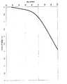
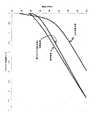
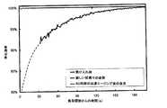
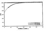
このフィルターのパティキュレートマターの添加中は、ガス流量は250kg/時間で、温度は240℃であり、背圧は差圧検出器により測定され、10秒毎にコンピュータに記録された。フィルターを通過する粒子は、Cambustion DMS500高速粒子質量分析器を使用して検出され、粒度分布は毎秒測定され、コンピュータに記録された。図1は、粒子数によって、このフィルターの初期の不良な浄化効率と、フィルターに収集されるパティキュレートマター量が増加するにつれて如何にしてこれが徐々に改善されるかを示している。約250秒後、約3×10¹³の粒子がフィルターを通過したと算出された。再生後、凝集式粒子数測定器(CPC)を使用する同型フィルターでの一連の別の実験により、初期の浄化効率が70%未満であったことが確認された。図2は、フィルターに保持されるパティキュレートマターの量が増加するにつれて、フィルターにかかる背圧が増加し、背圧の不均衡に大きい部分は、フィルター中における比較的少量のパティキュレートマターの蓄積から生じていることを示している。During the addition of particulate matter on this filter, the gas flow rate was 250 kg / hour, the temperature was 240 ° C., the back pressure was measured by a differential pressure detector and recorded in a computer every 10 seconds. Particles passing through the filter were detected using a Cambustion DMS500 fast particle mass analyzer and the particle size distribution was measured every second and recorded on a computer. FIG. 1 shows the initial poor purification efficiency of this filter and how it gradually improves as the amount of particulate matter collected in the filter increases with the number of particles. After about 250 seconds, it was calculated that about 3 × 10¹³ particles passed through the filter. After regeneration, a series of separate experiments with the same type of filter using an agglomerated particle number counter (CPC) confirmed that the initial purification efficiency was less than 70%. FIG. 2 shows that as the amount of particulate matter retained in the filter increases, the back pressure applied to the filter increases, and the large portion of the back pressure imbalance is the accumulation of a relatively small amount of particulate matter in the filter. It shows that it has arisen from.
実施例2−耐熱材料を添加した酸化触媒でのフィルターの触媒化
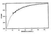
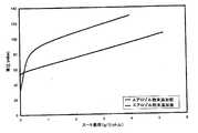
水性分散液の形態で約2μmの平均粒子径を有していることがMalvern Mastersizer2000により特徴付けられた乾燥ゼオライト粉末(ZSM−5、13g)を、実施例1で使用されたフィルターの流入側に、そこに捕集されたパティキュレートマターを、650℃に3時間維持された電気炉中で空気で燃焼させることにより完全に除去した後に、分配した。吸入面の架橋網目構造が導入されるフィルターをDPG装置に配し、該装置を、乱流空気流がフィルター基体の上流側に入るように、燃料なし、すなわちディーゼルパティキュレートの生成がないファンのみのモードで運転した。ゼオライトを、フィルター中に運ばれるエアロゾルを形成するように、フィルターの上流の導管のハウジングに配されたボスを介して、上流の乱流空気流内に250メッシュのふるいを通してそれを添加して、フィルターの流入側に均一に分散させた。エアロゾルの粒子径は、Cambustion DMS500により、約0.2μmを中心に分散していることが決定され、水性分散液として、一次粒子のかなりの凝集が存在していることが示唆された。ついで、フィルターに、DPGを使用して実施例1におけるようなパティキュレートマターを添加した。浄化効率を、Cambustion DMS500を使用して、先に記載したようにしてモニターし、結果を図3に示した。浄化効率は、ゼオライト粉末の添加がないものと比較して劇的に改善されていた。さらに、背圧対パティキュレート添加曲線も、粉末が存在しない場合と比較して、劇的に低下しており、この効果は、フィルターにおけるパティキュレートマター保持の初期段階中において背圧の増加が少ないためであった。Example 2-Catalysis of filter with oxidation catalyst with addition of refractory material Dry zeolite powder characterized by Malvern Mastersizer 2000 (ZSM-5) having an average particle size of about 2 μm in the form of an aqueous dispersion , 13 g) is completely removed by burning the particulate matter collected in the inflow side of the filter used in Example 1 with air in an electric furnace maintained at 650 ° C. for 3 hours. And then dispensed. A filter in which a cross-linking network structure of the suction surface is introduced is arranged in the DPG device, and the device is installed only in a fan without fuel, that is, without generation of diesel particulates, so that the turbulent air flow enters the upstream side of the filter base. Drove in mode. Add the zeolite through a 250 mesh screen into the upstream turbulent air flow through a boss placed in the conduit housing upstream of the filter to form an aerosol that is carried into the filter; Dispersed uniformly on the inflow side of the filter. The particle size of the aerosol was determined to be dispersed around about 0.2 μm by the Cambustion DMS500, suggesting that there is considerable aggregation of primary particles as an aqueous dispersion. The particulate matter as in Example 1 was then added to the filter using DPG. The purification efficiency was monitored as described above using a Cambustion DMS500 and the results are shown in FIG. The purification efficiency was dramatically improved compared to that without the addition of zeolite powder. In addition, the back pressure vs. particulate addition curve is also dramatically reduced compared to the absence of powder, and this effect is a small increase in back pressure during the initial stage of particulate matter retention in the filter. Because of that.
ついで、フィルターを、電気炉において650℃で3時間、空気中で再生し、パティキュレートマターの添加プロセスを繰り返した。パティキュレートマターの添加及び再生の全サイクルを全3回繰り返したところ、測定された最終浄化効率は、パティキュレートマターの添加中、全ての時点で非常に高いままであった−実験誤差内で、浄化効率は、ゼオライト粉末がフィルター中に添加された後の最初の添加中と同じ(99%より多い)であった。 The filter was then regenerated in air for 3 hours at 650 ° C. in an electric furnace and the particulate matter addition process was repeated. The entire cycle of particulate matter addition and regeneration was repeated a total of 3 times, and the final purification efficiency measured remained very high at all time points during particulate matter addition-within experimental error, The purification efficiency was the same (greater than 99%) during the first addition after the zeolite powder was added into the filter.
図4は、数回のフィルター添加/再生サイクル後の背圧/パティキュレートマター添加曲線を示す。背圧は、粉末が添加されない初期の挙動よりも、かなり低いままであった。よって、この添加された少量の無機粉末は、浄化効率を劇的に改善し、通常の使用中のフィルターの背圧に非常に望ましい低下をもたらした。 FIG. 4 shows the back pressure / particulate matter addition curve after several filter addition / regeneration cycles. The back pressure remained considerably lower than the initial behavior when no powder was added. Thus, this small amount of added inorganic powder dramatically improved the purification efficiency and resulted in a very desirable reduction in the back pressure of the filter during normal use.
比較例3−選択式触媒還元触媒を用いて触媒化されたフィルター−耐熱材料の添加なし
水銀ポロシメトリーにより推定された平均孔径14μm、空孔率42%、0.305mmのチャネル壁厚を有する円形断面(直径5.66インチ(14.4cm))及び6インチ(15.24cm)長の炭化ケイ素フィルターを、銅交換された(2.5重量%の銅)チャバサイトゼオライトアンモニアSCR触媒の分散液を用いて、フィルターの長さ全体にわたって、それがチャネル壁に0.5g/in3(8.2g/cm3)含むように処理した。Comparative Example 3-Filter Catalyzed Using Selective Catalytic Reduction Catalyst-No Addition of Heat Resistant Material Circular with an average pore size estimated by mercury porosimetry of 14 μm, a porosity of 42%, and a channel wall thickness of 0.305 mm A cross section (diameter 5.66 inch (14.4 cm)) and 6 inch (15.24 cm) long silicon carbide filters were dispersed in a copper exchanged (2.5 wt% copper) chabazite zeolite ammonia SCR catalyst. Was used to treat the entire length of the filter so that it contained 0.5 g / in3 (8.2 g / cm3 ) in the channel wall.
ついで、フィルターに、DPGを使用して、実施例1のパティキュレートマターを添加した。浄化効率及び背圧変化を、先に記載したようにしてモニターし、結果をそれぞれ図5及び6に示した。 Subsequently, the particulate matter of Example 1 was added to the filter using DPG. Purification efficiency and back pressure changes were monitored as described above and the results are shown in FIGS. 5 and 6, respectively.
実施例4−耐熱性添加材料と共に選択式触媒還元触媒を用いて触媒化されたフィルター
比較例3で使用されたものと同じフィルターを、電気炉で650℃で加熱し、全てのパティキュレートマターを燃焼させ、ついで冷却されたとき、ゼオライト(11g、ZSM−5)を、実施例2に記載したものと同じ方法を使用して、フィルターの流入側上にエアロゾルとして均一に分散させた。パティキュレートマターの添加中の浄化性能及び背圧を、先のようにして測定し、結果を、それぞれ図7及び図8に示した。Example 4-Filter catalyzed using selective catalytic reduction catalyst with heat resistant additive material The same filter as used in Comparative Example 3 was heated in an electric furnace at 650 ° C, and all particulate matter was removed. When combusted and then cooled, the zeolite (11 g, ZSM-5) was uniformly dispersed as an aerosol on the inflow side of the filter using the same method as described in Example 2. The purification performance and back pressure during the addition of particulate matter were measured as described above, and the results are shown in FIGS. 7 and 8, respectively.
ついで、フィルターを、1リットルの酸化触媒(95g/ft3、2:1の重量比の白金とパラジウムで、平方インチ当たり350セルのコーディエライトモノリシックフロースルー基体にコート)の下流のベンチ搭載Euro IV適合、2リットル直噴、コモンレールエンジン(例えば、乗用車に適したもの)の排ガスシステムに、フィルターの向きを粉末処理チャネルがフィルターのガス流入側になるようにして、装備した。エンジンは、次のような2工程サイクルを使用して運転した。The filter was then bench-mounted Euro downstream of 1 liter of oxidation catalyst (95 g / ft3 , platinum and palladium in a 2: 1 weight ratio, coated on cordierite monolithic flow-through substrate at 350 cells per square inch). An exhaust gas system of an IV compatible, 2 liter direct injection, common rail engine (eg suitable for passenger cars) was equipped with the orientation of the filter so that the powder treatment channel was on the gas inlet side of the filter. The engine was operated using a two-step cycle as follows.
工程1:エンジン速度3000rpm、エンジン負荷290Nm、持続時間30分、酸化触媒の流入口でのガス温度は560℃、酸化触媒及び流入口を出てからフィルターまでのガス温度は545℃であった。Step 1: The engine speed was 3000 rpm, the engine load was 290 Nm, the duration was 30 minutes, the gas temperature at the oxidation catalyst inlet was 560 ° C., and the gas temperature from the oxidation catalyst and the inlet to the filter was 545 ° C.
工程2:エンジン速度1800rpm、エンジン負荷75Nm、インシリンダーディーゼル燃料ポスト噴射、継続時間30分、酸化触媒への流入口のガス温度490℃、酸化触媒及び流入口を出てからフィルターまでのガス温度は600℃であった。Step 2: Engine speed 1800 rpm, engine load 75 Nm, in-cylinder diesel fuel post injection,
50ppmの硫黄含有量の標準的なディーゼル燃料を使用した。工程1及び2を、全20時間の間、連続して繰り返した。ついで、フィルターを排気システムから取り除き、電気炉において650℃で3時間処理することにより、あらゆるパティキュレートマターを取り除いた。比較例1に先に記載されたようにして、パティキュレートマターの添加中、DPGを使用して浄化効率及び背圧をモニターし、結果をぞれぞれ図9及び10に示した。 A standard diesel fuel with a sulfur content of 50 ppm was used.
ゼオライトの添加により達成される浄化効率及び背圧の有意な改善は、フィルターが、約40000kmに等価な間、エンジンについてエージングがなされた後でさえも保持されていた。 The significant improvement in purification efficiency and back pressure achieved by the addition of zeolite was retained even after the filter was aged for as long as the filter was equivalent to about 40,000 km.
実施例5−選択式触媒還元触媒で触媒化されたフィルター−触媒化耐熱材料を添加
比較例3と同じ寸法及びSCR触媒を有するフィルターを、DPGについて試験し、浄化効率及び背圧性能が比較例3と同様であったことを見出した。ついで、パティキュレートマターを、電気炉において650℃で燃焼させることにより完全に除去し、ついで、冷却されたとき、銅交換された(2.5重量%の銅)チャバサイトゼオライト(36g)及びゼオライトZSM5(6g)の混合物を、実施例2に記載されたものと同じ方法を使用し、フィルターの吸入面側にエアロゾルとして均一に分散させた。Example 5 Addition of Catalytic Heat-Resistant Material Catalyzed with Selective Catalytic Reduction Catalyst A filter having the same dimensions and SCR catalyst as Comparative Example 3 was tested for DPG and the purification efficiency and back pressure performance were comparative examples 3 was found to be the same. The particulate matter was then completely removed by burning in an electric furnace at 650 ° C. and then, when cooled, copper exchanged (2.5 wt% copper) chabazite zeolite (36 g) and zeolite A mixture of ZSM5 (6 g) was uniformly dispersed as an aerosol on the suction side of the filter using the same method as described in Example 2.
触媒化材料の添加の前後の浄化効率及び背圧性能を、それぞれ図11及び12に示す。 The purification efficiency and back pressure performance before and after the addition of the catalytic material are shown in FIGS. 11 and 12, respectively.
浄化効率及び背圧の双方における有意な改善の達成と同様に、触媒化された材料の添加がフィルターのNOx触媒性能を増加させることになり、これが図13に示されている。これらの結果は、10%の酸素(O2)、10%の水蒸気、残りが窒素(N2)中、800℃で16時間のリーン熱水エージング後に得られ、顕著な改善を示している。酸化触媒とフィルターとの間の排ガス中に尿素液(Adブルー)を噴射するために尿素噴射器を取り付けた実施例4に記載のものと同じエンジンセットアップを使用して、エージング部分を試験した。<10ppmの硫黄のディーゼル燃料を使用した。初期段階後、所望のフィルター流入温度を達成するために、一連のエンジン負荷でエンジンを運転した。試験条件は以下の通りであった。「アルファ」はNH3/NOx比として定義される。エンジンのエンジン制御策中にプログラムされた排ガス再循環バルブ位置を、EGRを止めるために無視して、工程3−5を、合理的な期間(時間ではない)で終了させた。一連の工程1〜5の全体は、順次直ぐに実施した。
図13において、右から左へのピークが工程1から5を表している。図11及び12にそれぞれ示されているような、浄化効率及び触媒化材料の添加の前後におけるフィルターの背圧性能の改善に加えて、図13は比較例3のフィルター(「標準的SCRフィルター」と標識)と比較したNOx転換活性の顕著な改善を示していることが分かる。 In FIG. 13, peaks from right to left represent
Claims (7)
Translated fromJapanese(a)吸入面と排出面を有し、吸入面と排出面が多孔質構造により離間している多孔質基体と;
(b)吸入面上に触媒フィルターケーキを含み、該ケーキが、シリケートゼオライト、アルミノシリケートゼオライト、金属置換アルミノシリケートゼオライト、非ゼオライト性モレキュラーシーブ、及び酸化物からなる群から選択される耐熱材料を含み、該酸化物は、アルミナ、シリカ、ジルコニア、セリア、クロミア、マグネシア、カルシア、チタニア、及びそれらの任意の2以上の混合酸化物からなる群から選択され、該耐熱材料は、0.2μmを越え、5μm未満の平均サイズを有する粒子として存在し、該耐熱材料が0.0488g/cm3(0.8g/in3)未満の量で存在する、フィルター。In the filter for filtering particulate matter from lean burn exhaust gas,
(A) a porous substrate having a suction surface and a discharge surface, the suction surface and the discharge surface being separated by a porous structure;
And (b)a catalyst filtercakes on the suction surface,heat-resistant material in which the cake is selected zeolite, aluminosilicate zeolites, metal-substituted aluminosilicate zeolites, non-zeolitic molecular sieves, from the group consisting及beauty oxides And theoxide is selected from the group consisting of alumina, silica, zirconia, ceria, chromia, magnesia, calcia, titania, and any two or more mixed oxides thereof, and the heat-resistant material is 0.2 μm The filteris present as particles having an average size greater than 5 μm and less than0.0488g /cm3(0.8 g / in3) .
Applications Claiming Priority (3)
| Application Number | Priority Date | Filing Date | Title |
|---|---|---|---|
| US35088910P | 2010-06-02 | 2010-06-02 | |
| US61/350,889 | 2010-06-02 | ||
| PCT/IB2011/001205WO2011151711A1 (en) | 2010-06-02 | 2011-06-02 | Diesel particulate filter |
Publications (2)
| Publication Number | Publication Date |
|---|---|
| JP2013534463A JP2013534463A (en) | 2013-09-05 |
| JP5865356B2true JP5865356B2 (en) | 2016-02-17 |
Family
ID=43736417
Family Applications (1)
| Application Number | Title | Priority Date | Filing Date |
|---|---|---|---|
| JP2013512999AActiveJP5865356B2 (en) | 2010-06-02 | 2011-06-02 | Diesel particulate filter |
Country Status (9)
| Country | Link |
|---|---|
| US (2) | US9352277B2 (en) |
| EP (1) | EP2576021B1 (en) |
| JP (1) | JP5865356B2 (en) |
| KR (2) | KR101999496B1 (en) |
| CN (1) | CN103079683B (en) |
| BR (1) | BR112012030599B8 (en) |
| GB (1) | GB201100595D0 (en) |
| RU (1) | RU2587086C2 (en) |
| WO (1) | WO2011151711A1 (en) |
Families Citing this family (74)
| Publication number | Priority date | Publication date | Assignee | Title |
|---|---|---|---|---|
| DE102011002936A1 (en)* | 2011-01-20 | 2012-07-26 | Ford Global Technologies, Llc | Particle sensor, exhaust system and method for determining particles in the exhaust gas |
| JP6395602B2 (en)* | 2011-07-13 | 2018-09-26 | ハルドール・トプサー・アクチエゼルスカベット | Catalyst fine particle filter and coating method of fine particle filter |
| GB201207313D0 (en) | 2012-04-24 | 2012-06-13 | Johnson Matthey Plc | Filter substrate comprising three-way catalyst |
| GB2513364B (en) | 2013-04-24 | 2019-06-19 | Johnson Matthey Plc | Positive ignition engine and exhaust system comprising catalysed zone-coated filter substrate |
| GB201302686D0 (en)* | 2013-02-15 | 2013-04-03 | Johnson Matthey Plc | Filter comprising three-way catalyst |
| FR3003478B1 (en)* | 2013-03-22 | 2016-12-23 | Peugeot Citroen Automobiles Sa | PARTICLE FILTER |
| GB2512648B (en) | 2013-04-05 | 2018-06-20 | Johnson Matthey Plc | Filter substrate comprising three-way catalyst |
| RU2629762C2 (en) | 2013-05-31 | 2017-09-01 | Джонсон Мэтти Паблик Лимитед Компани | Catalytic filter for exhaust gas processing |
| US9278343B2 (en)* | 2013-08-30 | 2016-03-08 | Johnson Matthey Public Limited Company | Zeolite blend catalysts for treating exhaust gas |
| JP6800014B2 (en)* | 2013-10-03 | 2020-12-16 | ユミコア・アクチエンゲゼルシャフト・ウント・コムパニー・コマンディットゲゼルシャフトUmicore AG & Co.KG | Exhaust aftertreatment system |
| US9616384B2 (en)* | 2014-06-11 | 2017-04-11 | Basf Se | Base metal catalyst |
| JP6379910B2 (en)* | 2014-09-17 | 2018-08-29 | 株式会社Ihi | Ammonia synthesis catalyst, method for producing ammonia synthesis catalyst, and ammonia synthesis method |
| KR102429402B1 (en)* | 2014-10-21 | 2022-08-05 | 바스프 코포레이션 | Emissions treatment systems with twc catalysts and scr-hct catalysts |
| EP3454968A1 (en)* | 2016-05-09 | 2019-03-20 | Unifrax I LLC | Catalyzed filtration media with high surface area material and method for making the same |
| WO2018054929A1 (en)* | 2016-09-20 | 2018-03-29 | Umicore Ag & Co. Kg | Diesel particle filter |
| GB201622179D0 (en)* | 2016-12-23 | 2017-02-08 | Johnson Matthey Plc | Gasoline particulate filter |
| DE102017219940A1 (en)* | 2017-11-09 | 2019-05-09 | Bayerische Motoren Werke Aktiengesellschaft | Method for operating a particle filter |
| DE102017219937B4 (en)* | 2017-11-09 | 2024-05-08 | Bayerische Motoren Werke Aktiengesellschaft | Method for introducing ash particles into an exhaust system of a motor vehicle |
| JP7158141B2 (en)* | 2017-11-27 | 2022-10-21 | エヌ・イーケムキャット株式会社 | Slurry composition for catalyst, method for producing the same, method for producing catalyst using the same, and method for producing Cu-containing zeolite |
| KR102085652B1 (en)* | 2017-12-29 | 2020-03-06 | 현대자동차 주식회사 | Hydrocarbon Trap Comprising Metal-impregnated Zeolite Particles Having Regular Mesopores and Method of Preparing the Same |
| JP7387643B2 (en)* | 2018-02-05 | 2023-11-28 | ビーエーエスエフ コーポレーション | Quaternary conversion catalyst with improved filter properties |
| WO2019161775A1 (en)* | 2018-02-26 | 2019-08-29 | Basf Corporation | Catalyst for gasoline engine exhaust gas aftertreatment |
| DE102018108346A1 (en) | 2018-04-09 | 2019-10-10 | Umicore Ag & Co. Kg | Coated wall flow filter |
| DE102018110804B4 (en)* | 2018-05-04 | 2024-06-27 | Umicore Ag & Co. Kg | Coated wall flow filter |
| DE102018111246A1 (en) | 2018-05-09 | 2019-11-14 | Umicore Ag & Co. Kg | Method for coating a wall-flow filter |
| JP2021536422A (en) | 2018-08-31 | 2021-12-27 | コーニング インコーポレイテッド | Method for manufacturing a honeycomb body having an inorganic filtration deposit |
| US11946405B2 (en) | 2018-08-31 | 2024-04-02 | Basf Corporation | Four-way conversion catalyst for the treatment of an exhaust gas stream |
| JP7608327B2 (en) | 2018-08-31 | 2025-01-06 | コーニング インコーポレイテッド | Method for manufacturing a honeycomb body having an inorganic filtration deposit - Patents.com |
| EP3847142A4 (en) | 2018-09-03 | 2022-04-20 | Corning Incorporated | Honeycomb body with porous material |
| DE102018127957A1 (en) | 2018-11-08 | 2020-05-14 | Umicore Ag & Co. Kg | Particle filter with multiple coatings |
| DE102018127953B4 (en)* | 2018-11-08 | 2025-03-20 | Umicore Ag & Co. Kg | Wall-flow filter with high filtration efficiency |
| DE102018127955A1 (en) | 2018-11-08 | 2020-05-14 | Umicore Ag & Co. Kg | Catalytically active particle filter with high filtration efficiency |
| KR102563441B1 (en)* | 2018-11-12 | 2023-08-03 | 현대자동차 주식회사 | Apparatus for purifying exhaust gas |
| DE102019100099B4 (en)* | 2019-01-04 | 2022-09-08 | Umicore Ag & Co. Kg | Process for the production of catalytically active wall-flow filters, catalytically active wall-flow filters and their use |
| DE102019103765B4 (en) | 2019-02-14 | 2023-01-12 | Umicore Ag & Co. Kg | Process for the production of automotive exhaust gas catalysts |
| US12264608B2 (en) | 2019-04-22 | 2025-04-01 | Basf Mobile Emissions Catalysts Llc | Catalyzed gasoline particulate filter |
| US11268413B2 (en)* | 2019-05-07 | 2022-03-08 | Ford Global Technologies, Llc | Method and system for gasoline particulate filter |
| CN110227538A (en)* | 2019-06-11 | 2019-09-13 | 一汽解放汽车有限公司 | The preparation method of the high activity DPF coating of NOx and PM is removed simultaneously |
| DE102019121084A1 (en) | 2019-08-05 | 2021-02-11 | Umicore Ag & Co. Kg | Catalyst substrates with porous coating |
| GB201911704D0 (en) | 2019-08-15 | 2019-10-02 | Johnson Matthey Plc | Treatment of particulate filters |
| GB201911702D0 (en)* | 2019-08-15 | 2019-10-02 | Johnson Matthey Plc | Particulate filters |
| KR102843140B1 (en) | 2019-11-29 | 2025-08-06 | (주)에이에스피 | Polymer bead and the manufacturing method thereof |
| DE102020103292A1 (en) | 2020-02-10 | 2021-08-12 | Umicore Ag & Co. Kg | Using ultrasound to clean wall flow filter substrates |
| GB2592258B (en) | 2020-02-21 | 2024-01-24 | Johnson Matthey Plc | Improvements in or relating to particulate filters |
| US20230173535A1 (en)* | 2020-04-28 | 2023-06-08 | Corning Incorporated | Aerosol deposition apparatus, method, and filter body with deposits |
| DE102020131366A1 (en) | 2020-11-26 | 2022-06-02 | Umicore Ag & Co. Kg | Emission control system for stoichiometric combustion engines |
| EP4015066A1 (en) | 2020-12-15 | 2022-06-22 | UMICORE AG & Co. KG | Catalytically active particle filter with high filtration efficiency |
| EP4015064B1 (en) | 2020-12-15 | 2025-01-22 | Umicore AG & Co. KG | Catalytically active particle filter with high filtration efficiency |
| EP4015065B1 (en) | 2020-12-15 | 2025-02-26 | Umicore AG & Co. KG | Catalytically active particle filter with high filtration efficiency |
| EP4015067A1 (en) | 2020-12-15 | 2022-06-22 | UMICORE AG & Co. KG | Catalytically active particle filter with high filtration efficiency |
| US12357981B2 (en) | 2021-02-12 | 2025-07-15 | Johnson Matthey Public Limited Company | Particulate filters |
| US20220258201A1 (en) | 2021-02-12 | 2022-08-18 | Johnson Matthey Public Limited Company | Powder spraying system, powder spraying nozzle and method |
| JP7717468B2 (en)* | 2021-02-16 | 2025-08-04 | 株式会社キャタラー | Exhaust gas purification catalyst |
| JP7717467B2 (en)* | 2021-02-16 | 2025-08-04 | 株式会社キャタラー | Exhaust gas purification catalyst |
| EP4063003A1 (en) | 2021-03-23 | 2022-09-28 | UMICORE AG & Co. KG | Filter for the aftertreatment of exhaust gases of internal combustion engines |
| DE102021107130B4 (en) | 2021-03-23 | 2022-12-29 | Umicore Ag & Co. Kg | Device for increasing the fresh filtration of petrol particle filters |
| DE202021103624U1 (en) | 2021-07-06 | 2022-10-14 | Umicore Ag & Co. Kg | WC applicator |
| JP7690073B2 (en) | 2021-08-20 | 2025-06-09 | ジョンソン、マッセイ、パブリック、リミテッド、カンパニー | Particulate filter improvements or improvements relating thereto |
| KR20240018530A (en) | 2021-08-27 | 2024-02-13 | 존슨 맛쎄이 퍼블릭 리미티드 컴파니 | Method for forming an inorganic oxide coating on a monolithic article |
| DE102021125536A1 (en) | 2021-10-01 | 2023-04-06 | Umicore Ag & Co. Kg | Catalytically active particle filter with high filtration efficiency |
| EP4159310A1 (en) | 2021-10-01 | 2023-04-05 | UMICORE AG & Co. KG | Catalytic coating |
| DE202021106828U1 (en) | 2021-12-15 | 2023-03-24 | Umicore Ag & Co. Kg | coating chamber |
| DE102022002854A1 (en) | 2022-08-05 | 2024-02-08 | Umicore Ag & Co. Kg | Catalytically active particle filter with high filtration efficiency and oxidation function |
| GB2621175B (en)* | 2022-08-05 | 2024-12-25 | Johnson Matthey Plc | Coated filters |
| DE102022121499A1 (en) | 2022-08-25 | 2024-03-07 | Umicore Ag & Co. Kg | Applicator for applying coating medium to substrates |
| EP4335547A1 (en) | 2022-09-12 | 2024-03-13 | Johnson Matthey Public Limited Company | Method of forming an inorganic oxide coating on a monolith article |
| EP4374952A1 (en) | 2022-11-28 | 2024-05-29 | Johnson Matthey Public Limited Company | Coatings on a monolith article |
| EP4400202A1 (en) | 2023-01-16 | 2024-07-17 | Johnson Matthey Public Limited Company | Coatings on a monolith article |
| WO2024161104A1 (en) | 2023-01-30 | 2024-08-08 | Johnson Matthey Public Limited Company | Catalytic wall flow filter |
| DE202023100970U1 (en) | 2023-03-01 | 2023-03-16 | Umicore Ag & Co. Kg | coating device |
| WO2025027274A1 (en) | 2023-08-02 | 2025-02-06 | Johnson Matthey Public Limited Company | Treatment of particulate filters |
| EP4501463A1 (en) | 2023-08-02 | 2025-02-05 | Johnson Matthey Plc | Treatment of particulate filters |
| US20250205623A1 (en) | 2023-12-20 | 2025-06-26 | Johnson Matthey Public Limited Company | Methods and apparatus relating to wall-flow filters |
| EP4624045A1 (en) | 2024-03-28 | 2025-10-01 | Johnson Matthey Public Limited Company | Method of forming an inorganic oxide coating on a monolith article |
Family Cites Families (29)
| Publication number | Priority date | Publication date | Assignee | Title |
|---|---|---|---|---|
| GB1000019A (en) | 1963-03-07 | 1965-08-04 | Ici Ltd | Improvements in or relating to films |
| DE10020170C1 (en) | 2000-04-25 | 2001-09-06 | Emitec Emissionstechnologie | Process for removing soot particles from the exhaust gas of internal combustion engine comprises feeding gas through collecting element, and holding and/or fluidizing until there is sufficient reaction with nitrogen dioxide in exhaust gas |
| DE3141713A1 (en) | 1981-10-21 | 1983-05-11 | Degussa Ag, 6000 Frankfurt | CATALYST FOR REDUCING THE TEMPERATURE OF DIESEL RUSS |
| DE3716446A1 (en)* | 1987-05-16 | 1988-12-01 | Dornier System Gmbh | CATALYTIC DIESEL RUSSIA FILTER |
| JPH0373866A (en) | 1989-05-24 | 1991-03-28 | Yasushi Ishii | Phase indicator circuit |
| WO1993007363A1 (en) | 1991-10-03 | 1993-04-15 | Toyota Jidosha Kabushiki Kaisha | Device for purifying exhaust of internal combustion engine |
| JP3750178B2 (en) | 1995-04-05 | 2006-03-01 | 株式会社デンソー | Exhaust gas purification filter and manufacturing method thereof |
| GB9805815D0 (en) | 1998-03-19 | 1998-05-13 | Johnson Matthey Plc | Manufacturing process |
| US7179430B1 (en)* | 1998-07-07 | 2007-02-20 | Corning Incorporated | Diesel exhaust gas filter |
| FI107828B (en) | 1999-05-18 | 2001-10-15 | Kemira Metalkat Oy | Systems for cleaning exhaust gases from diesel engines and method for cleaning exhaust gases from diesel engines |
| US6306335B1 (en) | 1999-08-27 | 2001-10-23 | The Dow Chemical Company | Mullite bodies and methods of forming mullite bodies |
| CN1298963A (en)* | 1999-12-09 | 2001-06-13 | 中国科学技术大学 | Chemical gas-phase deposition method and equipment for metal oxide or alloy film |
| US6468501B1 (en) | 2000-09-14 | 2002-10-22 | Chevrontexaco Corporation | Method for heteroatom lattice substitution in large and extra-large pore borosilicate zeolites |
| US20030101718A1 (en) | 2001-10-06 | 2003-06-05 | Marcus Pfeifer | Method and device for the catalytic conversion of gaseous pollutants in the exhaust gas of combustion engines |
| FR2853255B1 (en)* | 2003-04-01 | 2005-06-24 | Saint Gobain Ct Recherches | FILTRATION STRUCTURE, ESPECIALLY PARTICULATE FILTER FOR EXHAUST GASES OF AN INTERNAL COMBUSTION ENGINE |
| US7229597B2 (en) | 2003-08-05 | 2007-06-12 | Basfd Catalysts Llc | Catalyzed SCR filter and emission treatment system |
| DE102004040548A1 (en) | 2004-08-21 | 2006-02-23 | Umicore Ag & Co. Kg | Process for coating a Wandflußfilters with finely divided solids and thus obtained particulate filter and its use |
| JP4907860B2 (en) | 2004-11-11 | 2012-04-04 | 株式会社キャタラー | Filter catalyst |
| EP1775022B1 (en)* | 2005-10-12 | 2021-01-27 | Center for Research and Technology-Hellas (CERTH) | Process of producing a catalytic coating and catalyst filters |
| GB0607851D0 (en) | 2006-04-24 | 2006-05-31 | Johnson Matthey Plc | Particulate matter generator |
| DE102006034119A1 (en)* | 2006-07-24 | 2008-01-31 | Robert Bosch Gmbh | Filter for the removal of particles from a gas stream and process for its preparation |
| US7998423B2 (en)* | 2007-02-27 | 2011-08-16 | Basf Corporation | SCR on low thermal mass filter substrates |
| KR20090114480A (en)* | 2007-02-27 | 2009-11-03 | 바스프 카탈리스트 엘엘씨 | Binary Catalysts for Selective Ammonia Oxidation |
| JP5777339B2 (en) | 2007-04-26 | 2015-09-09 | ジョンソン、マッセイ、パブリック、リミテッド、カンパニーJohnson Matthey Publiclimited Company | Transition metal / zeolite SCR catalyst |
| WO2008136232A1 (en)* | 2007-04-27 | 2008-11-13 | Ngk Insulators, Ltd. | Honeycomb filter |
| JP5291966B2 (en) | 2008-03-25 | 2013-09-18 | 日本碍子株式会社 | Catalyst support filter |
| EP2364200A1 (en) | 2008-11-26 | 2011-09-14 | Corning Incorporated | Coated particulate filter and method |
| CN101711991B (en)* | 2009-10-15 | 2012-07-18 | 清华大学 | Fe molecular sieve composite catalyst and preparation method thereof |
| GB201000019D0 (en) | 2010-01-04 | 2010-02-17 | Johnson Matthey Plc | Coating a monolith substrate with catalyst component |
- 2011
- 2011-01-14GBGBGB1100595.6Apatent/GB201100595D0/ennot_activeCeased
- 2011-06-02KRKR1020187023796Apatent/KR101999496B1/enactiveActive
- 2011-06-02CNCN201180027307.5Apatent/CN103079683B/enactiveActive
- 2011-06-02WOPCT/IB2011/001205patent/WO2011151711A1/enactiveApplication Filing
- 2011-06-02KRKR1020127034425Apatent/KR20130111979A/ennot_activeCeased
- 2011-06-02RURU2012157520/05Apatent/RU2587086C2/enactive
- 2011-06-02JPJP2013512999Apatent/JP5865356B2/enactiveActive
- 2011-06-02USUS13/701,306patent/US9352277B2/enactiveActive
- 2011-06-02EPEP11731071.4Apatent/EP2576021B1/enactiveActive
- 2011-06-02BRBR112012030599Apatent/BR112012030599B8/enactiveIP Right Grant
- 2016
- 2016-05-23USUS15/161,384patent/US9517454B2/enactiveActive
Also Published As
| Publication number | Publication date |
|---|---|
| US20130243659A1 (en) | 2013-09-19 |
| JP2013534463A (en) | 2013-09-05 |
| RU2012157520A (en) | 2014-07-20 |
| US9352277B2 (en) | 2016-05-31 |
| RU2587086C2 (en) | 2016-06-10 |
| KR20130111979A (en) | 2013-10-11 |
| WO2011151711A1 (en) | 2011-12-08 |
| BR112012030599B8 (en) | 2020-05-12 |
| EP2576021B1 (en) | 2014-12-03 |
| BR112012030599A2 (en) | 2017-06-13 |
| KR101999496B1 (en) | 2019-07-11 |
| CN103079683B (en) | 2015-09-02 |
| EP2576021A1 (en) | 2013-04-10 |
| US20160310935A1 (en) | 2016-10-27 |
| CN103079683A (en) | 2013-05-01 |
| US9517454B2 (en) | 2016-12-13 |
| GB201100595D0 (en) | 2011-03-02 |
| BR112012030599B1 (en) | 2020-04-22 |
| KR20180098416A (en) | 2018-09-03 |
Similar Documents
| Publication | Publication Date | Title |
|---|---|---|
| JP5865356B2 (en) | Diesel particulate filter | |
| JP6687666B2 (en) | Exhaust system for vehicle positive ignition internal combustion engine | |
| CN105283241B (en) | The filter base of catalyst support coatings comprising zone coated | |
| JP2019069437A (en) | Wall-flow filter comprising catalytic washcoat | |
| KR101718574B1 (en) | Exhaust system for a vehicular positive ignition internal combustion engine | |
| CN112371164A (en) | Selective catalytic reduction catalyst system | |
| GB2554517A (en) | Catalyst binders for filter substrates | |
| EP2988851B1 (en) | Positive ignition engine with filter substrate comprising zone-coated catalyst washcoat |
Legal Events
| Date | Code | Title | Description |
|---|---|---|---|
| A621 | Written request for application examination | Free format text:JAPANESE INTERMEDIATE CODE: A621 Effective date:20140530 | |
| A977 | Report on retrieval | Free format text:JAPANESE INTERMEDIATE CODE: A971007 Effective date:20150423 | |
| A131 | Notification of reasons for refusal | Free format text:JAPANESE INTERMEDIATE CODE: A131 Effective date:20150519 | |
| A601 | Written request for extension of time | Free format text:JAPANESE INTERMEDIATE CODE: A601 Effective date:20150817 | |
| A601 | Written request for extension of time | Free format text:JAPANESE INTERMEDIATE CODE: A601 Effective date:20150918 | |
| A601 | Written request for extension of time | Free format text:JAPANESE INTERMEDIATE CODE: A601 Effective date:20151014 | |
| A521 | Request for written amendment filed | Free format text:JAPANESE INTERMEDIATE CODE: A523 Effective date:20151117 | |
| TRDD | Decision of grant or rejection written | ||
| A01 | Written decision to grant a patent or to grant a registration (utility model) | Free format text:JAPANESE INTERMEDIATE CODE: A01 Effective date:20151201 | |
| A61 | First payment of annual fees (during grant procedure) | Free format text:JAPANESE INTERMEDIATE CODE: A61 Effective date:20151225 | |
| R150 | Certificate of patent or registration of utility model | Ref document number:5865356 Country of ref document:JP Free format text:JAPANESE INTERMEDIATE CODE: R150 | |
| R250 | Receipt of annual fees | Free format text:JAPANESE INTERMEDIATE CODE: R250 | |
| R250 | Receipt of annual fees | Free format text:JAPANESE INTERMEDIATE CODE: R250 | |
| R250 | Receipt of annual fees | Free format text:JAPANESE INTERMEDIATE CODE: R250 | |
| R250 | Receipt of annual fees | Free format text:JAPANESE INTERMEDIATE CODE: R250 | |
| R250 | Receipt of annual fees | Free format text:JAPANESE INTERMEDIATE CODE: R250 | |
| R250 | Receipt of annual fees | Free format text:JAPANESE INTERMEDIATE CODE: R250 | |
| R250 | Receipt of annual fees | Free format text:JAPANESE INTERMEDIATE CODE: R250 |