JP5865113B2 - Image processing apparatus, image processing system, image processing method, and image processing program - Google Patents
Image processing apparatus, image processing system, image processing method, and image processing programDownload PDFInfo
- Publication number
- JP5865113B2 JP5865113B2JP2012033923AJP2012033923AJP5865113B2JP 5865113 B2JP5865113 B2JP 5865113B2JP 2012033923 AJP2012033923 AJP 2012033923AJP 2012033923 AJP2012033923 AJP 2012033923AJP 5865113 B2JP5865113 B2JP 5865113B2
- Authority
- JP
- Japan
- Prior art keywords
- brightness
- pixel
- main scanning
- scanning line
- document area
- Prior art date
- Legal status (The legal status is an assumption and is not a legal conclusion. Google has not performed a legal analysis and makes no representation as to the accuracy of the status listed.)
- Active
Links
Images


Classifications
- H—ELECTRICITY
- H04—ELECTRIC COMMUNICATION TECHNIQUE
- H04N—PICTORIAL COMMUNICATION, e.g. TELEVISION
- H04N1/00—Scanning, transmission or reproduction of documents or the like, e.g. facsimile transmission; Details thereof
- H04N1/04—Scanning arrangements, i.e. arrangements for the displacement of active reading or reproducing elements relative to the original or reproducing medium, or vice versa
- H—ELECTRICITY
- H04—ELECTRIC COMMUNICATION TECHNIQUE
- H04N—PICTORIAL COMMUNICATION, e.g. TELEVISION
- H04N1/00—Scanning, transmission or reproduction of documents or the like, e.g. facsimile transmission; Details thereof
- H04N1/40—Picture signal circuits
- H04N1/409—Edge or detail enhancement; Noise or error suppression
- H04N1/4092—Edge or detail enhancement
- G—PHYSICS
- G06—COMPUTING OR CALCULATING; COUNTING
- G06T—IMAGE DATA PROCESSING OR GENERATION, IN GENERAL
- G06T5/00—Image enhancement or restoration
- G06T5/90—Dynamic range modification of images or parts thereof
- G06T5/94—Dynamic range modification of images or parts thereof based on local image properties, e.g. for local contrast enhancement
- G—PHYSICS
- G06—COMPUTING OR CALCULATING; COUNTING
- G06T—IMAGE DATA PROCESSING OR GENERATION, IN GENERAL
- G06T7/00—Image analysis
- G06T7/10—Segmentation; Edge detection
- G06T7/12—Edge-based segmentation
- H—ELECTRICITY
- H04—ELECTRIC COMMUNICATION TECHNIQUE
- H04N—PICTORIAL COMMUNICATION, e.g. TELEVISION
- H04N1/00—Scanning, transmission or reproduction of documents or the like, e.g. facsimile transmission; Details thereof
- H04N1/40—Picture signal circuits
- H04N1/407—Control or modification of tonal gradation or of extreme levels, e.g. background level
Landscapes
- Engineering & Computer Science (AREA)
- Physics & Mathematics (AREA)
- General Physics & Mathematics (AREA)
- Theoretical Computer Science (AREA)
- Multimedia (AREA)
- Signal Processing (AREA)
- Computer Vision & Pattern Recognition (AREA)
- Image Input (AREA)
- Facsimile Scanning Arrangements (AREA)
- Image Processing (AREA)
- Facsimile Image Signal Circuits (AREA)
Description
Translated fromJapanese本明細書で論じられる実施態様は、画像処理装置、画像処理システム、画像処理方法及び画像処理プログラムに関する。 The embodiments discussed herein relate to an image processing apparatus, an image processing system, an image processing method, and an image processing program.
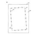
原稿を読み取って得られる画像データから原稿領域の画像を切り出す画像処理装置が知られている。図1は、原稿を読み取って得られる画像データの模式図を示す。画像データ100は、原稿の像を撮像素子で読み取った画素の集合で形成される原稿領域101と、撮像素子が原稿の外側の光を検出した画素の集合で形成される背景領域102とを含む。画像データから原稿領域の画像を切り出すために、原稿領域101と背景領域102との境界線103上の点であるエッジ点104が検出される。図1において各「×」印は、それぞれ境界線103上の異なるエッジ点104を表す。 An image processing apparatus that cuts out an image of a document area from image data obtained by reading a document is known. FIG. 1 is a schematic diagram of image data obtained by reading a document.
原稿の端部を検出する技術として、シェーディングデータに基づいて原稿の端部となる特定領域を決定し、画像データの特定領域における値を所定値に置換することで、原稿の端部のノイズを除去する画像読取装置が知られている。画像読取装置のマスク補正回路は、シェーディング補正を行うために利用するシェーディングデータに基づいて、ガンマ補正回路から入力される画像データについて原稿の端部となる特定領域の判定を行う。特定領域と判定された画像データの値は所定値に変換されて後段の各回路に出力される。 As a technique for detecting the edge of an original, a specific area that is an edge of the original is determined based on shading data, and a value in the specific area of the image data is replaced with a predetermined value, thereby reducing noise at the edge of the original. An image reading device to be removed is known. The mask correction circuit of the image reading apparatus determines a specific area serving as an edge portion of the document with respect to the image data input from the gamma correction circuit based on the shading data used for performing the shading correction. The value of the image data determined to be the specific area is converted into a predetermined value and output to each subsequent circuit.
また、ラインセンサの各素子間の濃度差を抑制する画像読取装置が知られている。この画像読取装置は、所定方向に沿って受光素子が配列されたラインセンサと、ラインセンサの読み取り領域のうち、少なくとも記録媒体に記録された画像を読み取る第1の読み取り領域以外の第2の読み取り領域に設けられた白基準板を備える。また画像読取装置は、第2の読み取り領域に対応した第2の受光素子により読み取られた第2の読み取り領域の画素値に基づいて、第1の読み取り領域に対応した第1の受光素子により読み取られた第1の読み取り領域の画素値を補正する補正手段を備える。 An image reading apparatus that suppresses a difference in density between each element of a line sensor is also known. This image reading apparatus includes a line sensor in which light receiving elements are arranged along a predetermined direction, and a second reading other than a first reading area that reads at least an image recorded on a recording medium among reading areas of the line sensor. A white reference plate is provided in the area. Further, the image reading apparatus reads the first light receiving element corresponding to the first reading area based on the pixel value of the second reading area read by the second light receiving element corresponding to the second reading area. Correction means for correcting the pixel value of the read first reading area.
図1の領域102において明度が均一でない現象、すなわち明度にムラが生じる現象が生じることがある。背景領域の明度のムラの原因の一例として、画像読取装置の原稿裏当て(以下、単に「裏当て」と表記する)の傾きやたわみがある。裏当ての傾きやたわみが生じると、裏当てと光学センサとの間の間隔に差ができるため、裏当てから反射する光を読み取った画素で形成される背景領域102で明度ムラが生じる。裏当ての傾きやたわみは、裏当ての支持部材の故障の他、例えば厚みのある原稿を読み取る際にも生じることがある。 In the
背景領域102の明度のムラによって、原稿領域101との境界付近の背景領域102の明度が変動すると、エッジ点104の位置の誤検出の一因となる。本明細書に記載される装置、システム、方法及びコンピュータプログラムは、原稿領域を含む画像データの背景領域に明度ムラがある場合の原稿領域のエッジ点の検出精度を向上することを目的とする。 If the brightness of the
装置の一観点によれば、原稿領域を含む画像データを入力する入力部と、原稿領域より外側の主走査ラインである第1主走査ライン上の各画素の明度を記憶する記憶部と、第1主走査ラインに続く第2主走査ライン上の第1部分の画素の明度と第2部分の画素の明度とに応じて、記憶部に記憶される第1主走査ライン上の各画素の明度を補正する補正部と、補正部により補正された第1主走査ライン上の各画素の明度と、第1主走査ライン上の各画素にそれぞれ対応する第2主走査ライン上の各画素の明度との間の差に応じて、第2主走査ライン上に位置する原稿領域のエッジ点を検出するエッジ点検出部を備える画像処理装置が与えられる。 According to one aspect of the apparatus, an input unit that inputs image data including a document region, a storage unit that stores the brightness of each pixel on a first main scanning line that is a main scanning line outside the document region, The brightness of each pixel on the first main scan line stored in the storage unit in accordance with the brightness of the pixel in the first portion on the second main scan line following the one main scan line and the brightness of the pixel in the second portion. , The brightness of each pixel on the first main scanning line corrected by the correcting unit, and the brightness of each pixel on the second main scanning line corresponding to each pixel on the first main scanning line An image processing apparatus is provided that includes an edge point detection unit that detects an edge point of the document area located on the second main scanning line in accordance with the difference between the first and second scanning lines.
装置の他の一観点によれば、画像読取装置と、該画像読取装置との間の通信により画像読取装置が読み込む画像を受信するコンピュータ装置とを有する画像処理システムが与えられる。画像処理システムは、画像読取装置により読み込まれる原稿領域を含んだ画像データ中の、原稿領域より外側の主走査ラインである第1主走査ライン上の各画素の明度を記憶する記憶部と、第1主走査ラインに続く第2主走査ライン上の第1部分の画素の明度と第2部分の画素の明度とに応じて、記憶部に記憶される第1主走査ライン上の各画素の明度を補正する補正部と、補正部により補正された第1主走査ライン上の各画素の明度と、第1主走査ライン上の各画素にそれぞれ対応する第2主走査ライン上の各画素の明度との間の差に応じて、第2主走査ライン上に位置する原稿領域のエッジ点を検出するエッジ点検出部を備える。 According to another aspect of the apparatus, an image processing system is provided that includes an image reading device and a computer device that receives an image read by the image reading device through communication with the image reading device. The image processing system includes a storage unit that stores the brightness of each pixel on the first main scanning line that is the main scanning line outside the document area in the image data including the document area read by the image reading device; The brightness of each pixel on the first main scan line stored in the storage unit in accordance with the brightness of the pixel in the first portion on the second main scan line following the one main scan line and the brightness of the pixel in the second portion. , The brightness of each pixel on the first main scanning line corrected by the correcting unit, and the brightness of each pixel on the second main scanning line corresponding to each pixel on the first main scanning line Is provided with an edge point detection unit for detecting an edge point of the document area located on the second main scanning line in accordance with the difference between the first and second scanning lines.
方法の一観点によれば、画像処理方法が与えられる。画像処理方法は、原稿領域を含む画像データを取得する処理と、原稿領域より外側の主走査ラインである第1主走査ライン上の各画素の明度を記憶部に記憶する処理と、第1主走査ラインに続く第2主走査ライン上の第1部分の画素の明度と第2部分の画素の明度とに応じて、記憶部に記憶される第1主走査ライン上の各画素の明度を補正する処理と、補正された第1主走査ライン上の各画素の明度と、第1主走査ライン上の各画素にそれぞれ対応する第2主走査ライン上の各画素の明度との間の差に応じて、第2主走査ライン上に位置する原稿領域のエッジ点を検出する処理を画像処理装置に実行させる。 According to one aspect of the method, an image processing method is provided. The image processing method includes a process of acquiring image data including a document area, a process of storing the brightness of each pixel on a first main scanning line that is a main scanning line outside the document area, and a first main The brightness of each pixel on the first main scan line stored in the storage unit is corrected according to the brightness of the pixel of the first portion on the second main scan line following the scan line and the brightness of the pixel of the second portion. Between the corrected brightness of each pixel on the first main scan line and the brightness of each pixel on the second main scan line corresponding to each pixel on the first main scan line. In response, the image processing apparatus is caused to execute processing for detecting an edge point of the document area located on the second main scanning line.
コンピュータプログラムの一観点によれば、制御部を備えた情報処理装置に実行させるための画像処理プログラムが与えられる。画像処理プログラムは、原稿領域を含む画像データを取得する処理と、原稿領域より外側の主走査ラインである第1主走査ライン上の各画素の明度を記憶部に記憶する処理と、第1主走査ラインに続く第2主走査ライン上の第1部分の画素の明度と第2部分の画素の明度とに応じて、記憶部に記憶される第1主走査ライン上の各画素の明度を補正する処理と、補正された第1主走査ライン上の各画素の明度と、第1主走査ライン上の各画素にそれぞれ対応する第2主走査ライン上の各画素の明度との間の差に応じて、第2主走査ライン上に位置する原稿領域のエッジ点を検出する処理を制御部に実行させる。 According to one aspect of the computer program, an image processing program to be executed by an information processing apparatus including a control unit is provided. The image processing program includes processing for acquiring image data including a document area, processing for storing the brightness of each pixel on the first main scanning line, which is a main scanning line outside the document area, in a storage unit, and first main The brightness of each pixel on the first main scan line stored in the storage unit is corrected according to the brightness of the pixel of the first portion on the second main scan line following the scan line and the brightness of the pixel of the second portion. Between the corrected brightness of each pixel on the first main scan line and the brightness of each pixel on the second main scan line corresponding to each pixel on the first main scan line. In response, the control unit is caused to execute processing for detecting an edge point of the document area located on the second main scanning line.
本明細書に記載される装置、システム、方法又はコンピュータプログラムによれば、原稿領域を含む画像データの背景領域に明度ムラがある場合の原稿領域のエッジ点の検出精度が向上される。 According to the apparatus, system, method, or computer program described in this specification, the detection accuracy of the edge point of the document area when the background area of the image data including the document area has uneven brightness is improved.
<1.ハードウエア構成>
以下、添付する図面を参照して好ましい実施例について説明する。図2は、画像処理システムのハードウエア構成図である。画像処理システム1は、画像読取装置10及びコンピュータ装置30を備える。画像読取装置10は、2次元の原稿を読み取って、この原稿に対応する画像信号を生成する。画像読取装置10は、例えば、複数の光源で露光された2次元原稿を走査して読み取る画像読取装置であってよい。このような、例えば画像読取装置の例として、例えばフィーダスキャナ、フラットベッドスキャナ、ハンディスキャナ等の各種スキャナ装置が挙げられる。以下、フィーダスキャナの例によって実施例の説明を行う。<1. Hardware configuration>
Hereinafter, preferred embodiments will be described with reference to the accompanying drawings. FIG. 2 is a hardware configuration diagram of the image processing system. The image processing system 1 includes an
コンピュータ装置30は、有線又は無線の通信回線を介して画像読取装置10との間で通信が可能であり、この通信回線を経由して画像読取装置10が読み取った原稿の画像信号を画像読取装置10から受信する。 The
画像読取装置10は、CPU(Central Processing Unit: 中央処理ユニット)11、メモリ12、イメージセンサ13、AFE(Analog Front-End Processor)14と、シェーディング処理部15と、ブロックバッファ16を備える。また、画像読取装置10は、画像処理制御部17と、画像メモリ18と、調停部19と、モータ20と、モータ制御部21と、原稿センサ22と、入力部23と、出力部24と、インタフェース(I/F)25を備える。 The
CPU11は、メモリ12に格納されたコンピュータプログラムに従い画像読取装置10の動作を制御する。ある実施例では、CPU11は、画像読取装置10が読み取る原稿画像の画像処理を行ってもよい。メモリ12にはこのような画像処理用のコンピュータプログラムが格納されてもよい。メモリ12には、CPU11により実行されるコンピュータプログラムや、このコンピュータプログラムの実行の際に使用されるデータが格納される。メモリ12は、プログラムを記憶するための非揮発性記憶装置や、データを一時的に記憶するための揮発性メモリを含んでいてよい。 The
イメージセンサ13は、2次元の原稿を撮像して、原稿に対応する画像信号を出力する。イメージセンサ13は、例えば、1次元又は2次元に配列されたCCD(Charge Coupled Device)センサやCMOS(Complementary Metal Oxide Semiconductor)センサ等の撮像素子と、この撮像素子に原稿の像を結像する光学系を備える。AFE14は、イメージセンサ13から出力される画像信号に対して増幅やその他の信号処理を施した後、処理された画像信号をシェーディング処理部15へ入力する。 The
シェーディング処理部15は、AFE14から受信した画像信号を、画像データとしてブロックバッファ16に収容し、この画像データにシェーディング処理を施した後に、画像処理制御部17に出力する。画像処理制御部17は、シェーディング処理が施された後の画像データに所定の画像処理を施し、画像データを画像メモリ18に格納する。他の実施例においてシェーディング処理部15は、シェーディング処理が施された後の画像データを画像メモリ18に格納し、画像処理制御部17は、画像メモリ18から画像データを入力してもよい。調停部19は、画像処理制御部17が画像処理の際に行うメモリ12に対するアクセスと、CPU11によるメモリ12へのアクセスとが競合しないように、これらのアクセスを調停する。 The
モータ20は、画像読取装置10の原稿トレイからイメージセンサ13による原稿読み取り位置まで原稿を搬送するローラに回転駆動力を与える。モータ制御部21は、原稿の読み取り時に原稿を搬送するモータ20の動作を制御する。原稿センサ22は、原稿読み取り位置まで原稿を運ぶ搬送路上の所定の位置に原稿が存在するか否かを検出する。 The
ある実施例では、シェーディング処理部15、画像処理制御部17、調停部19及びモータ制御部21は、論理回路として画像読取装置10に実装されてよい。論理回路は、例えば、LSI(large scale integration)やASIC(Application Specific Integrated Circuit)、FPGA(Field-Programming Gate Array)等であってよい。他の実施例では、シェーディング処理部15、画像処理制御部17、調停部19及びモータ制御部21は、CPUやDSP(digital signal processor)等のプロセッサと、プログラムを格納するメモリを含む電子回路として画像読取装置10に実装されてよい。 In an embodiment, the
入力部23は、ユーザによる入力操作を受け付ける入力装置である。入力部23は、例えば、ボタン、スクロールホイール、キーパッド、キーボード、ポインティングデバイス、タッチパネル等であってよい。出力部24は、画像読取装置10から各種情報をユーザに提示するための出力装置である。例えば、出力部24は、ユーザに提示する情報を利用者に可視的に表示する表示デバイスであってよい。出力部24は、発光素子や、液晶ディスプレイ、有機エレクトロルミネッセンスディスプレイ等の表示装置であってよい。または、出力部24は、音声信号を出力するスピーカやその駆動回路であってよい。 The
I/F25は、画像読取装置10とコンピュータ装置30との間の有線及び/又は無線による通信インタフェースである。画像読取装置10は、読み取った原稿の画像データをI/F25を介してコンピュータ装置30へ送信することが可能である。画像読取装置10は、画像読取装置10の動作に関する設定情報や指示をI/F25を介してコンピュータ装置30から受信する。ある実施例では、画像読取装置10は、コンピュータ装置30により処理が施された画像データをI/F25を介して受信してよい。 The I /
一方、コンピュータ装置30は、CPU31と、補助記憶装置32と、メモリ33と、入力部34と、出力部35と、媒体読取部36と、I/F37を備える。CPU31は、補助記憶装置32に格納されたコンピュータプログラムを実行することにより、コンピュータプログラムに応じた情報処理を実行する。ある実施例では、CPU31は、画像読取装置10により読み取られた原稿画像の画像処理を行ってもよい。補助記憶装置32にはこのような画像処理用のコンピュータプログラムが格納されてもよい。補助記憶装置32は、コンピュータプログラムを記憶するための、不揮発性記憶装置や、読み出し専用メモリ(ROM: Read Only Memory)やハードディスクなどを含んでいてもよい。 On the other hand, the
メモリ33には、CPU31が現在実行中のプログラムや、このプログラムによって一時的に使用されるデータが記憶される。メモリ33は、ランダムアクセスメモリ(RAM: Random Access Memory)を含んでいてよい。入力部34は、ユーザによる入力操作を受け付ける入力装置である。入力部34は、例えば、キーパッド、キーボード、ポインティングデバイス、タッチパネル等であってよい。 The
出力部35は、コンピュータ装置30によって処理された信号を出力する出力装置である。例えば、出力部35は、コンピュータ装置30によって処理された情報を利用者に可視的に表示する表示デバイスであってよい。出力部35は、例えば、液晶ディプレイ、CRT(Cathode Ray Tube)ディスプレイ、有機エレクトロルミネッセンスディスプレイなどの表示装置であってよい。または、出力部35は、音声信号を出力するスピーカやその駆動回路であってよい。 The
媒体読取部36は、コンピュータに読み取り可能な可搬型記録媒体に記憶されたデータを読み取る入力装置である。媒体読取部36は、例えばCD−ROMドライブ装置やDVD−ROMドライブ装置、フレキシブルディスクドライブ装置、CD−Rドライブ装置や、DVD−Rドライブ装置、MOドライブ装置、フラッシュメモリ装置へのアクセス装置であってよい。 The
I/F37は、画像読取装置10とコンピュータ装置30との間の有線及び/又は無線による通信インタフェースである。コンピュータ装置30は、画像読取装置10が読み取った原稿の画像データを、I/F37を経由して受信することが可能である。コンピュータ装置30は、画像読取装置10の動作に関する設定情報や指示をI/F37を介して画像読取装置10へ送信する。 The I /
<2.第1実施例>
<2.1.機能構成>
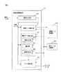
図3は、画像処理制御部17の機能構成例を示す図である。画像処理制御部17は、画像入力部50と、背景データ検出部51と、背景データ補正部52と、エッジ検出部53を備える。なお、図3は、以下の説明に関係する機能を中心として示している。このため、画像処理制御部17は図示の構成要素以外の他の構成要素を含んでいてよい。また、画像処理制御部17は、背景データ記憶部54に後述の背景データを記憶する。画像処理制御部17は、所定の設定データを設定データ記憶部55から読み取る。背景データ記憶部54及び設定データ記憶部55は、図2に示すメモリ12の記憶領域の一部として実現される。<2. First Example>
<2.1. Functional configuration>
FIG. 3 is a diagram illustrating a functional configuration example of the image
他の実施例では、画像入力部50、背景データ検出部51、背景データ補正部52及びエッジ検出部53により行われる処理の一部又は全部を、画像処理制御部17に代わってCPU11が実行してもよい。また、他の実施例では、これらの処理の一部又は全部をコンピュータ装置30のCPU31によって実行してもよい。背景データ記憶部54及び設定データ記憶部55は、コンピュータ装置30のメモリ33の記憶領域の一部として実現されてもよい。 In another embodiment, the
CPU31にこれらの情報処理を実行させるコンピュータプログラムは、機械可読記録媒体に記録されて、媒体読取部36により読み取られて補助記憶装置32にインストールされてもよい。また、CPU31にこれらの情報処理を実行させるコンピュータプログラムは、図示しないネットワークインタフェースを介してネットワークからダウンロードされ、補助記憶装置32にインストールされてもよい。 A computer program that causes the
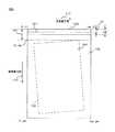
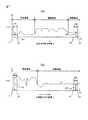
画像入力部50は、画像データを入力する。図4は、以下の説明に使用する画像データの例示の模式図である。画像データ100は、原稿の像をイメージセンサ13で読み取った画素の集合で形成される原稿領域101と、イメージセンサ13が原稿の外側の光を検出した画素の集合で形成される背景領域102とを含む。例えば、背景領域102は、原稿の裏当ての表面をイメージセンサ13で読み取った画素の集合で形成される。参照符号103は、原稿領域101と背景領域102との境界線を示す。 The
また、イメージセンサ13の主走査方向を矢印110で示し、副走査方向を矢印111で示す。画像データ100は、主走査方向110に(xe+1)個の画素を持ち、副走査方向111に(ye+1)個の画素を持つ。主走査方向110をX軸方向とし副走査方向111をY軸方向として画像データ100中の各画素の位置を座標(x,y)で表す。主走査方向110の始端及び終端のx座標をそれぞれ「0」及び「xe」とする。また、副走査方向111の始端及び終端のy座標をそれぞれ「0」及び「ye」とする。 The main scanning direction of the
画像データ100は、原稿領域101を含まない副走査方向の範囲120を有する。図4の例では、範囲120はY座標の値「0」〜「yb」の範囲には原稿領域101が含まれない。このような範囲120を以下の説明で「付帯領域」と表記することがある。付帯領域120は、例えば、原稿センサ22で搬送途中の原稿位置を読み取って、原稿の先端がイメージセンサ13による原稿読み取り位置へ達する前からイメージセンサ13の画像読み取りを開始させることによって生成することができる。他の実施例のフラットベッドスキャナは、原稿サイズを検出する原稿センサを備えてもよい。この実施例は、検出した原稿サイズよりも余計に副走査を行って付帯領域120を生成する。付帯領域120は、背景領域102と同様に、原稿の裏当ての表面をイメージセンサ13で読み取った画素の集合で形成される。 The
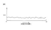
図3を参照する。背景データ検出部51は、裏当て表面がイメージセンサ13で読み取られた主走査ライン上の各画素の明度を検出し背景データdとして出力する。図5は、背景データdの一例の説明図である。図5のグラフは、裏当て表面がイメージセンサ13で読み取られた主走査ライン上の各座標xにおけるそれぞれの画素の明度を示す。 Please refer to FIG. The background
背景データ検出部51は、付帯領域120内のいずれか複数の主走査ライン上の各画素の明度を検出し、同じx座標について複数の主走査ライン間で明度を平均することにより、背景データdを算出してよい。背景データ検出部51は、付帯領域120内のいずれか1つの主走査ライン上で検出した明度を、背景データdとして出力してもよい。背景データ検出部51が出力した背景データdは、背景データ記憶部54に格納される。背景データdが検出される付帯領域120内の主走査ラインは、第1主走査ラインの一例である。 The background
図3を参照する。背景データ補正部52は、画像データ100においてエッジ点を検出する対象となる主走査ライン毎に、主走査ライン上の背景領域102の明度に背景データdの明度が近づくように背景データdを補正する。以下の説明において、エッジ点の検出の対象となるラインを「対象ライン」と表記することがある。対象ラインは第2主走査ラインの一例である。 Please refer to FIG. The background
図6に、対象ラインの例を示す。例示の対象ライン130は、主走査方向110に沿って座標(0,y1)から(xe,y1)まで延びている。後述の通り、エッジ検出部53は、原稿領域101と背景領域102との境界線103上のエッジ点104を対象ライン130上で検出する。画像処理制御部17は、画像データ100内の主走査ラインの中から、所定数のラインずつ飛ばして対象ライン130を選択してよい。他の実施例では、画像処理制御部17は、隣合って並ぶ複数の主走査ラインのそれぞれを対象ライン130として選択してよい。 FIG. 6 shows an example of the target line. The
図7の(A)は、ある対象ライン上の各画素の明度の例を示す。図7の(A)のグラフは、対象ライン上の各座標xにおけるそれぞれの画素の明度を示す。以下の説明において、対象ライン上の各画素の明度のデータを「画像データA」と表記する。図7の(A)は、比較的濃度の小さな原稿が、イメージセンサ13の中央付近で読み取られた場合の画像データAの例を示す。このため、対象ラインの各座標xのうち中央付近の原稿領域において明度が大きくなっており、対象ラインの始端側及び終端側での明度AL及びARが、中央付近の明度に比べて小さくなっている。 FIG. 7A shows an example of the brightness of each pixel on a certain target line. The graph in FIG. 7A shows the brightness of each pixel at each coordinate x on the target line. In the following description, the brightness data of each pixel on the target line is referred to as “image data A”. FIG. 7A shows an example of image data A when a document having a relatively low density is read near the center of the
図7の(B)は、他の対象ライン上の画像データAの例を示す。図7の(A)は、比較的濃度の小さな原稿がイメージセンサ13の始端側に寄った状態で読み取られた場合の画像データAの例を示す。原稿領域に含まれる始端側での明度ALが終端側での明度ARに比べて著しく大きくなっている。 FIG. 7B shows an example of image data A on another target line. FIG. 7A shows an example of the image data A when a document having a relatively low density is read in a state of being close to the start end side of the
背景データ補正部52は、対象ライン上の画像データAの複数の部分の明度を検出して、対象ライン上の背景領域102の明度に背景データdの明度が近づくように背景データdを補正する。背景データ補正部52は、明度判定部56と、選択部57と、係数決定部58を備える。明度判定部56は、画像データAの始端側及び終端側での明度AL及びARを検出する。 The background
図7の(A)及び図7の(B)に、始端側及び終端側での明度AL及びARの検出範囲を示す。始端側の明度ALが検出される範囲D1はx座標の値がx1〜x2の範囲であり、終端側の明度ARが検出される範囲D2はx座標の値がx3〜x4の範囲である。明度判定部56は、範囲D1内の画像データAの複数の画素の明度の平均をALとし、範囲D2内の画像データAの複数の画素の明度の平均をARとして算出する。 FIG. 7A and FIG. 7B show the detection ranges of brightness AL and AR on the start side and the end side. The range D1 in which the lightness AL on the start side is detected is an x coordinate value range from x1 to x2, and the range D2 in which the lightness AR on the end side is detected is a range from x3 to x4. The
他の実施例では、明度判定部56は、範囲D1内の画像データAのいずれかの1画素の明度をALとし、範囲D2内の画像データAのいずれかの1画素の明度をARとして選択してもよい。なお、座標x1、x2、x3及びx4の設定値は設定データ記憶部55に格納され、明度判定部56によって読み出される。座標x1、x2、x3及びx4の値は画像読取装置10の製造時に設定されてもよく、ユーザが画像読取装置10の入力部23やコンピュータ装置30の入力部34を操作することによって設定されてもよい。他の実施例では、座標x1、x2、x3及びx4の値は固定値でもよい。 In another embodiment, the
明度判定部56は、明度AL及びARの差の絶対値|AL−AR|が所定の閾値T1より小さいか否かを判断する。絶対値|AL−AR|が閾値T1より小さければ、原稿がイメージセンサ13の中央付近で読み取られており、明度AL及びARの両方が背景領域102の明度を持っていると判断することができる。この場合には、範囲D1及びD2での明度AL及びARの両方を背景データdの補正に使用できる。なお、閾値T1の設定値は設定データ記憶部55に格納され、明度判定部56によって読み出される。閾値T1の値は画像読取装置10の製造時に設定されてもよく、ユーザが画像読取装置10の入力部23やコンピュータ装置30の入力部34を操作することによって設定されてもよい。他の実施例では、閾値T1の値は固定値でもよい。 The
一方で、絶対値|AL−AR|が閾値T1以上であれば、原稿がイメージセンサ13の始端側又は終端側に寄った状態で読み取られており、始端側又は終端側の明度AL及びARのいずれか一方が、原稿領域101の明度を持っていると判断することができる。この場合には、明度AL及びARのうち原稿領域101の明度を持つ一方は背景データdの補正に使用できないため、背景領域102の明度を持つ他方のみが使用できる。 On the other hand, if the absolute value | AL−AR | is equal to or greater than the threshold value T1, the document is read in a state of approaching the start end side or the end side of the
絶対値|AL−AR|が閾値T1以上の場合、明度判定部56は、範囲D1及びD2と同じx座標の範囲における背景データdの明度BL及びBRを検出する。以下の説明において、範囲D1と同じx座標の範囲における背景データdの明度BLを、始点側の明度BLと表現することがある。また、範囲D2と同じx座標の範囲における背景データdの明度BRを、終端側の明度BRと表現することがある。図8の(A)は、始点側及び終端側における背景データdの明度BL及びBRの検出位置の説明図である。 When the absolute value | AL-AR | is equal to or greater than the threshold value T1, the
明度判定部56は、範囲D1内の背景データdの複数の画素の明度の平均をBLとし、範囲D2内の背景データdの複数の画素の明度の平均をBRとして算出する。他の実施例では、明度判定部56は、範囲D1内のいずれかの1画素の明度をBLとし、範囲D2内のいずれかの1画素の明度をBRとして選択してもよい。 The
明度判定部56は、範囲D1の背景データdと画像データAの明度の差の絶対値|BL−AL|と、範囲D2の背景データdと画像データAの明度の差の絶対値|BR−AR|のいずれが大きいかを判断する。範囲D1の明度差の絶対値|BL−AL|が、範囲D2の明度差の絶対値|BR−AR|よりも小さければ、範囲D1の画像データAの明度ALが背景領域102の明度を持っており、原稿は終端側に寄っていると判断することができる。 The
反対に、範囲D1の明度差の絶対値|BL−AL|が、範囲D2の明度差の絶対値|BR−AR|よりも小さくなければ、範囲D2の画像データAの明度ARが背景領域102の明度を持っており、原稿は始点側に寄っていると判断することができる。 Conversely, if the absolute value | BL-AL | of the brightness difference in the range D1 is not smaller than the absolute value | BR-AR | of the brightness difference in the range D2, the brightness AR of the image data A in the range D2 is the
明度差|AL−AR|が閾値T1以上の場合、選択部57は、明度判定部56の判定に従って、範囲D1及びD2のうち、画像データAの明度が背景領域102の明度を持っているいずれか一方の範囲を選択する。すなわち、選択部57は、範囲D1の背景データdと画像データAの明度差|BL−AL|が、範囲D2の明度差|BR−AR|よりも小さい場合には範囲D1を選択する。選択部57は、範囲D1の明度差|BL−AL|が、範囲D2の明度差|BR−AR|よりも小さくない場合には、範囲D2を選択する。このように範囲D1及びD2のいずれかを選択することによって、選択部57は、これらの範囲の画像データの明度AL及びARのうち一方を、背景データdの補正に使用する画像データAの明度として選択する。 When the brightness difference | AL−AR | is equal to or greater than the threshold value T1, the
係数決定部58は、明度判定部56の判定結果が以下の(ケース1)〜(ケース3)のいずれであるかに応じて定めた決定方法にしたがって、背景データdを補正するための補正係数Q(x)を定める。背景データ補正部52は、下式(1)により背景データdに補正係数Q(x)を乗ずることにより補正された背景データd’を算出する。
d’(x)=Q(x)×d(x) (1)
上式において、xは主走査ライン上のx座標を示し、Q(x)は、背景データdの各x座標における値d(x)に乗じる補正係数を示す。またd’(x)は、主走査ライン上の各x座標における補正された背景データd’の値を示す。The
d ′ (x) = Q (x) × d (x) (1)
In the above equation, x represents the x coordinate on the main scanning line, and Q (x) represents a correction coefficient by which the value d (x) at each x coordinate of the background data d is multiplied. D ′ (x) represents the value of the corrected background data d ′ at each x coordinate on the main scanning line.
(ケース1)明度AL及びARの差の絶対値|AL−AR|が所定の閾値T1より小さい場合には、係数決定部58は、範囲D1及びD2両方の画像データAの背景データdの明度に基づき、次式(2)の例により補正係数Q(x)を決定する。 (Case 1) When the absolute value | AL−AR | of the difference between the lightness values AL and AR is smaller than the predetermined threshold value T1, the
Q(x)=(AR/BR−AL/BL)/(xe)×x+AL/BL (2) Q (x) = (AR / BR−AL / BL) / (xe) × x + AL / BL (2)
図8の(B)は、式(1)の例による補正係数Q(x)により補正された背景データの例を示す。式(1)の補正係数Q(x)は、始端側のx座標「0」において値「AL/BL」を持ち、終端側のx座標「xe」において値「AR/BR」を有する一次関数である。このため、背景データdの始端側及び終端側の明度がそれぞれBL及びBRであるとき、補正された背景データd’の始端側及び終端側の明度はそれぞれAL及びARに近似する値となる。よって、対象ラインの画像データAの背景領域102に主走査方向110に沿って変化する明度ムラがあっても、背景領域102がある対象ラインの始端及び終端の範囲にて、背景データd’の明度を画像データAの背景領域102の明度に近づけることができる。 FIG. 8B shows an example of background data corrected by the correction coefficient Q (x) according to the example of Expression (1). The correction coefficient Q (x) in Expression (1) has a value “AL / BL” at the x coordinate “0” on the start side and a value “AR / BR” at the x coordinate “xe” on the end side. It is. Therefore, when the lightness on the start side and the end side of the background data d is BL and BR, respectively, the lightness on the start side and the end side of the corrected background data d ′ are values approximate to AL and AR, respectively. Therefore, even if the
明度AL及びARの差の絶対値|AL−AR|が所定の閾値T1より小さくない場合には、係数決定部58は、選択部57が選択した範囲の画像データAの背景データdの明度に基づき、次式(3)又は(4)の例により補正係数Q(x)を決定する。 When the absolute value | AL−AR | of the difference between the lightness values AL and AR is not smaller than the predetermined threshold value T1, the
(ケース2)選択部57が範囲D1を選択した場合
Q(x)=AL/BL (3)(Case 2) When the
(ケース3)選択部57が範囲D2を選択した場合
Q(x)=AR/BR (4)(Case 3) When the
図8の(C)は、式(3)の例による補正係数Q(x)により補正された背景データの例を示す。式(3)の補正係数Q(x)は、図7の(B)の例のように始端側の範囲D1が原稿領域101に含まれる場合に使用される。補正係数Q(x)は、背景領域102の明度ARを持つ終端側の範囲D2の背景データd’の明度をARに近づける。 FIG. 8C shows an example of background data corrected by the correction coefficient Q (x) according to the example of Expression (3). The correction coefficient Q (x) in the equation (3) is used when the
したがって、対象ラインの終端の範囲で、背景データd’の明度を画像データAの背景領域102の明度に近づけることができる。また、終端側明度ARのみを補正に用いることにより、原稿領域101内の始端側明度ALのために背景データdが背景領域102の明度と異なるように補正されることが防止される。 Therefore, the brightness of the background data d 'can be brought close to the brightness of the
終端側の範囲D2が原稿領域101に含まれる場合にも同様に、式(2)の例による補正係数Q(x)によって、対象ラインの始端の範囲で、背景データd’の明度を画像データAの背景領域102の明度に近づけることができる。また、原稿領域101内の終端側明度ARのために、背景データdが背景領域102の明度と異なるように補正されることが防止される。 Similarly, when the range D2 on the end side is included in the
図3を参照する。エッジ検出部53は、下式(5)の通り補正された背景データd’を画像データAから引くことによって、補正された画像データA’を算出する。
A’(x)=A(x)−d’(x) (5)
上式(5)において、A(x)は、対象ラインの画像データAの各x座標における明度値を示す。A(x)は、補正された画像データA’の各x座標における明度値を示す。Please refer to FIG. The
A ′ (x) = A (x) −d ′ (x) (5)
In the above equation (5), A (x) represents a lightness value at each x coordinate of the image data A of the target line. A (x) indicates a lightness value at each x coordinate of the corrected image data A ′.
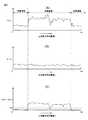
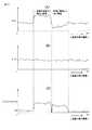
図9の(A)及び図9(B)は、画像データA及び補正された背景データd’の例を示す。図9の(C)に、図9(B)の補正された背景データd’によって図9の(A)の画像データAを補正した結果の一例を示す。補正された背景データd’の値は背景領域において画像データAの値に近似する。このため、対象ラインの背景領域の明度に関わらず、補正された画像データ(A−d’)の値は「0」に近似した値となる。 FIGS. 9A and 9B show examples of the image data A and the corrected background data d ′. FIG. 9C shows an example of the result of correcting the image data A in FIG. 9A with the corrected background data d ′ in FIG. 9B. The corrected value of the background data d 'approximates the value of the image data A in the background area. For this reason, the value of the corrected image data (A−d ′) is a value approximate to “0” regardless of the brightness of the background area of the target line.
エッジ検出部53は、補正された画像データA’が所定の閾値T2となる点をエッジ点の候補として検出する。なお、閾値T2の設定値は設定データ記憶部55に格納され、エッジ検出部53によって読み出される。閾値T2の値は画像読取装置10の製造時に設定されてもよく、ユーザが画像読取装置10の入力部23やコンピュータ装置30の入力部34を操作することによって設定されてもよい。他の実施例では、閾値T2の値は固定値でもよい。 The
<2.2.動作説明>
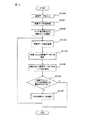
続いて、画像処理制御部17の動作について説明する。図10は、画像処理制御部17の動作の説明図である。ステップS100において画像処理システム1は、画像データを入力する。ステップS101において背景データ検出部51は、入力した画像データの付帯領域から背景データdを検出する。ステップS102において画像処理制御部17は、画像データのいずれかの主走査ラインを、エッジ点を検出する最初の対象ラインとして選択する。ステップS103において背景データ補正部52は、対象ライン上の画素の明度に応じて背景データdを補正する背景データ補正処理を行う。<2.2. Operation explanation>
Next, the operation of the image
図11は、背景データ補正処理の説明図である。ステップS200において明度判定部56は、画像データAの始端側範囲D1及び終端側範囲D2での明度AL及びARを検出する。ステップS201において明度判定部56は、明度AL及びARの差の絶対値|AL−AR|が所定の閾値T1より小さいか否かを判断する。絶対値|AL−AR|が所定の閾値T1より小さい場合(ステップS201:Y)に、処理はステップS202に進む。絶対値|AL−AR|が所定の閾値T1以上の場合(ステップS201:N)に、処理はステップS203に進む。 FIG. 11 is an explanatory diagram of the background data correction process. In step S200, the
ステップS202において係数決定部58は、範囲D1及びD2両方の画像データAの背景データdの明度に基づき、上式(2)の例により補正係数Qを決定する。その後に処理はステップS207に進む。 In step S202, the
ステップS203において明度判定部56は、範囲D1及びD2における背景データdの明度BL及びBRを検出する。ステップS204において明度判定部56は、範囲D1の背景データdと画像データAの明度の差の絶対値|BL−AL|が、範囲D2の背景データdと画像データAの明度の差の絶対値|BR−AR|より小さいか否かを判断する。絶対値|BL−AL|が絶対値|BR−AR|以上である場合(ステップS204:N)に処理はステップS205に進む。絶対値|BL−AL|が絶対値|BR−AR|より小さい場合(ステップS204:Y)に処理はステップS206に進む。 In step S203, the
ステップS205において選択部57は、範囲D2を選択する。係数決定部58は、選択された範囲D2の画像データAの背景データdの明度AR及びBRに基づき、上式(4)の例により補正係数Qを決定する。その後に処理はステップS207へ進む。ステップS206において範囲D1を選択する。係数決定部58は、選択された範囲D1の画像データAの背景データdの明度AL及びBLに基づき、上式(3)の例により補正係数Qを決定する。その後に処理はステップS207へ進む。ステップS207において背景データ補正部52は、背景データdに補正係数Qを乗ずることにより補正された背景データd’を算出する。その後に処理は終了する。 In step S205, the
図10を参照する。ステップS104においてエッジ検出部53は、補正された背景データd’を画像データAから引くことによって、補正された画像データA’を算出する。ステップS105においてエッジ検出部53は、補正された画像データA’が所定の閾値T2となる点をエッジ点の候補として検出する。 Please refer to FIG. In step S <b> 104, the
ステップS106において画像処理制御部17は、ステップS102で選択した対象ラインが、エッジ点検出の対象となる最後の主走査ラインであるか否かを判断する。対象ラインが最後の主走査ラインである場合(ステップS106:Y)に処理は終了する。対象ラインが最後の主走査ラインでない場合(ステップS106:N)に処理はステップS107へ進む。ステップS107において画像処理制御部17は、エッジ点を検出する次の対象ラインを選択する。その後に処理はステップS103へ戻る。 In step S <b> 106, the image
<2.3.効果>
本実施例によれば、対象ライン上の背景領域102の画像データAの明度の値が「0」に近くなるように、画像データAを補正された背景データd’で補正してからエッジ点を検出する。このため、背景領域102の画像データAの明度の大小に関わらず、エッジ点検出用の閾値T2を小さく設定することができるので、エッジ点の検出精度が向上される。図12の(A)及び図12の(B)を参照して、その理由を説明する。<2.3. Effect>
According to this embodiment, the edge point is corrected after the image data A is corrected with the corrected background data d ′ so that the brightness value of the image data A in the
図12の(A)は、背景データdで補正しない場合の画像データAを示す。裏当ての濃度や状態に応じて、背景領域102の明度は様々な値を取り得る。このため、エッジ点検出用に画像データと対比される閾値Txは、原稿毎の背景領域102の明度の違いに対応するためにマージンをもった比較的大きな値に設定される。閾値Txのマージンをより大きくすると、閾値Txと原稿領域の明度の差が小さくなるためエッジ点の検出精度が低下する。 (A) of FIG. 12 shows the image data A when not corrected with the background data d. The brightness of the
本実施例によれば、補正された画像データA’=A−dは、背景領域102の画像データAの明度に関わらず図12の(B)に示すように背景領域102にて値が小さくなる。このため、閾値Txのマージンをより少なくすることによってエッジ点の検出精度が向上させることができる。 According to this embodiment, the corrected image data A ′ = Ad has a small value in the
また、本実施例によれば、対象ライン毎に補正された背景データd’を用いて画像データAを補正する。このため背景領域に副走査方向に沿う明度ムラがあっても、明度ムラに追従するように画像データAを補正できる。このため、画像データAの背景領域に副走査方向に沿った明度ムラがあっても、エッジ点の検出精度が向上される。また、本実施例によれば、主走査方向に沿う対象ラインの複数の範囲D1及びD2の画像データAの明度AL及びARの両方を用いて補正された背景データd’を用いて画像データAを補正する。このため、背景領域に主走査方向に沿う明度ムラがあっても、明度ムラに追従するように画像データAを補正できる。このため、画像データAの背景領域に主走査方向に沿った明度ムラがあっても、エッジ点の検出精度が向上される。 Further, according to the present embodiment, the image data A is corrected using the background data d ′ corrected for each target line. For this reason, even if the background region has lightness unevenness along the sub-scanning direction, the image data A can be corrected so as to follow the lightness unevenness. For this reason, even if the background region of the image data A has lightness unevenness along the sub-scanning direction, the edge point detection accuracy is improved. Further, according to the present embodiment, the image data A using the background data d ′ corrected using both the brightness AL and AR of the image data A of the plurality of ranges D1 and D2 of the target line along the main scanning direction. Correct. For this reason, even if the background region has brightness unevenness along the main scanning direction, the image data A can be corrected so as to follow the brightness unevenness. For this reason, even if the background region of the image data A has brightness unevenness along the main scanning direction, the edge point detection accuracy is improved.
また、本実施例によれば、原稿領域が画像データAの始端側及び終端側に寄っているか否かを判断する。原稿領域が始端側及び終端側のいずれかに寄っていれば、始端側及び終端側のうち原稿領域でない方の範囲の画像データAの明度を用いて背景データdを補正する。このような補正により、背景データdの補正に原稿領域内の明度が使用されて補正後の背景データd’が背景領域の明度から離れることが防止される。この結果、補正後の画像データA’の背景領域の値が「0」から離れることが防止される。 Further, according to the present embodiment, it is determined whether or not the document area is close to the start side and the end side of the image data A. If the document area is closer to either the start side or the end side, the background data d is corrected using the brightness of the image data A in the range of the start side and the end side that is not the document area. Such correction prevents the lightness in the document area from being used for correcting the background data d, and the corrected background data d 'is prevented from leaving the lightness in the background area. As a result, the value of the background area of the corrected image data A ′ is prevented from leaving “0”.
<2.4.変形例>
本実施例では、背景データdの補正に用いる画像データAの明度AL及びARを検出する複数の領域として、対象ラインの始端側及び終端側の範囲D1及びD2が使用される。しかし、背景データdの補正に用いる画像データAの明度を検出する複数の領域は、2カ所に関わらず3カ所以上の領域であってもよい。また、背景データdの補正に用いる画像データAの明度を検出する複数の領域は、背景領域内であれば始端側及び終端側の範囲でなくともよい。背景データ補正部52は、背景領域内の複数箇所の明度差に基づき、内挿及び外挿処理によって主走査方向に沿った背景領域の明度を推定し、推定結果に基づいて背景データdを補正してよい。<2.4. Modification>
In the present embodiment, ranges D1 and D2 on the start end side and end end side of the target line are used as a plurality of areas for detecting the brightness AL and AR of the image data A used for correcting the background data d. However, the plurality of areas for detecting the brightness of the image data A used for the correction of the background data d may be three or more areas regardless of the two areas. Further, the plurality of areas for detecting the brightness of the image data A used for correcting the background data d need not be in the range of the start side and the end side as long as they are within the background area. The background
<3.第2実施例>
続いて、画像処理システム1の他の実施例について説明する。本実施例では、イメージセンサ13による原稿読み取りの際に、原稿の地の濃度が小さくても大きくてもエッジ点を検出できるように、中間的な濃度を有する裏当てが使用される。<3. Second Embodiment>
Next, another embodiment of the image processing system 1 will be described. In the present embodiment, a backing having an intermediate density is used so that the edge point can be detected when the
本実施例のエッジ検出部53は、下式(6)の通り補正された背景データd’と画像データAとの差の絶対値を、補正された画像データA’として算出する。
A’(x)=|A(x)−d’(x)| (6)The
A ′ (x) = | A (x) −d ′ (x) | (6)
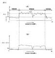
図13の(A)及び図13(B)は、画像データA及び補正された背景データd’の例を示す。図13の(C)に、図13(B)の補正された背景データd’によって図13の(A)の画像データAを補正した結果の一例を示す。背景データd’と画像データAとの差の絶対値を画像データA’とすることにより、原稿が背景領域より明るい領域であっても暗い領域であっても、補正された画像データ|A−d’|の値は正の値になる。エッジ検出部53は、補正された画像データA’が所定の閾値T3となる点をエッジ点の候補として検出する。なお、閾値T3の設定値は設定データ記憶部55に格納され、エッジ検出部53によって読み出される。閾値T3の値は画像読取装置10の製造時に設定されてもよく、ユーザが画像読取装置10の入力部23やコンピュータ装置30の入力部34を操作することによって設定されてもよい。他の実施例では、閾値T3の値は固定値でもよい。 FIGS. 13A and 13B show examples of image data A and corrected background data d ′. FIG. 13C shows an example of the result of correcting the image data A of FIG. 13A with the corrected background data d ′ of FIG. 13B. By setting the absolute value of the difference between the background data d ′ and the image data A as the image data A ′, the corrected image data | A− regardless of whether the document is brighter or darker than the background area. The value of d ′ | is a positive value. The
本実施例によれば、背景領域における画像データAの明度の値が「0」に近くなり、且つ原稿領域の画像データAの値が正の値となるように補正された画像データA’が補正される。このため、対象ラインの画像データAの背景領域の明度の大小に関わらず、各対象ライン間で一律の閾値T3をエッジ点検出用に使用することができる。このため、エッジ点の検出処理を簡略化することが可能となる。 According to this embodiment, the image data A ′ corrected so that the brightness value of the image data A in the background area is close to “0” and the value of the image data A in the document area is a positive value. It is corrected. Therefore, regardless of the brightness of the background area of the image data A of the target line, a uniform threshold value T3 can be used for edge point detection between the target lines. For this reason, it is possible to simplify the edge point detection process.
1 画像処理システム
10 画像読取装置
30 コンピュータ装置
50 画像入力部
51 背景データ検出部
52 背景データ補正部
53 エッジ検出部
54 背景データ記憶部DESCRIPTION OF SYMBOLS 1
Claims (8)
Translated fromJapanese前記原稿領域より外側の主走査ラインである第1主走査ライン上の各画素の明度を記憶する記憶部と、
第1主走査ラインに続く、少なくとも一部が前記原稿領域に含まれる第2主走査ライン上の第1部分の画素の明度と第2部分の画素の明度とに応じて、前記記憶部に記憶される第1主走査ライン上の各画素の明度を補正する補正部と、
前記補正部により補正された第1主走査ライン上の各画素の明度と、第1主走査ライン上の各画素にそれぞれ対応する第2主走査ライン上の各画素の明度との間の差に応じて、第2主走査ライン上に位置する前記原稿領域のエッジ点を検出するエッジ点検出部と、を備え、
第2主走査ライン上の前記第1部分と前記第2部分の内の一方は前記原稿領域より外側にあり、前記第1部分と前記第2部分の内の他方は前記原稿領域内、又は、前記原稿領域をはさんで前記一方と反対側であり且つ前記原稿領域より外側にある、
ことを特徴とする画像処理装置。An input unit for inputting image data including a document area;
A storage unit for storing brightness of each pixel on the first main scanning line which is a main scanning line outside the original region;
Stored in the storage unit in accordance with the brightness of the pixels of the first part and the brightness of the pixels of the second part on the second main scan lineat least partly following the first main scan line. A correction unit for correcting the brightness of each pixel on the first main scanning line,
The difference between the brightness of each pixel on the first main scanning line corrected by the correction unit and the brightness of each pixel on the second main scanning line corresponding to each pixel on the first main scanning line, respectively. And an edge point detection unit for detecting an edge point of the document area located on the second main scanning line,
One of the first part and the second part on the second main scanning line is outside the document area, and the other of the first part and the second part is in the document area, or Across the document area and opposite to the one and outside the document area,
The image processing apparatus according to claim andthis.
前記第1部分の画素と第2主走査ライン上の前記第1部分に対応する第1主走査ライン上の第3部分の画素との間の明度差、及び、前記第2部分の画素と第2主走査ライン上の前記第2部分に対応する第1主走査ライン上の第4部分の画素との間の明度差に応じて、前記第1部分の画素の明度及び前記第2部分の画素の明度の何れかを選択する選択部と、
前記選択部が選択した明度に応じて第1主走査ライン上の画素の明度を補正するための補正係数を決定する係数決定部と、
を備える請求項1に記載の画像処理装置。The correction unit is
Brightness difference between the third portion of the pixelof the first main scan on a line corresponding to a pixel andthe first portion of the second main scanning line of the firstpart,and,the pixel of the second portion The brightness of the pixels of the first portion and the pixels of the second portion according to the brightness difference with the pixelsof the fourth portionon the first main scan line corresponding to the second portion on the two main scan lines A selection unit for selecting one of the brightness values of
A coefficient determination unit that determines a correction coefficient for correcting the lightness of the pixels on the first main scanning line according to the lightness selected by the selection unit;
An image processing apparatus according to claim 1.
前記画像読取装置により読み込まれる原稿領域を含んだ画像データ中の、前記原稿領域より外側の主走査ラインである第1主走査ライン上の各画素の明度を記憶する記憶部と、
第1主走査ラインに続く、少なくとも一部が前記原稿領域に含まれる第2主走査ライン上の第1部分の画素の明度と第2部分の画素の明度とに応じて、前記記憶部に記憶される第1主走査ライン上の各画素の明度を補正する補正部と、
前記補正部により補正された第1主走査ライン上の各画素の明度と、第1主走査ライン上の各画素にそれぞれ対応する第2主走査ライン上の各画素の明度との間の差に応じて、第2主走査ライン上に位置する前記原稿領域のエッジ点を検出するエッジ点検出部と、を備え、
第2主走査ライン上の前記第1部分と前記第2部分の内の一方は前記原稿領域より外側にあり、前記第1部分と前記第2部分の内の他方は前記原稿領域内、又は、前記原稿領域をはさんで前記一方と反対側であり且つ前記原稿領域より外側にある、
ことを特徴とする画像処理システム。An image processing system comprising: an image reading device; and a computer device that receives an image read by the image reading device by communication between the image reading device,
A storage unit for storing brightness of each pixel on a first main scanning line which is a main scanning line outside the document region in image data including a document region read by the image reading device;
Stored in the storage unit in accordance with the brightness of the pixels of the first part and the brightness of the pixels of the second part on the second main scan lineat least partly following the first main scan line. A correction unit for correcting the brightness of each pixel on the first main scanning line,
The difference between the brightness of each pixel on the first main scanning line corrected by the correction unit and the brightness of each pixel on the second main scanning line corresponding to each pixel on the first main scanning line, respectively. And an edge point detection unit for detecting an edge point of the document area located on the second main scanning line,
One of the first part and the second part on the second main scanning line is outside the document area, and the other of the first part and the second part is in the document area, or Across the document area and opposite to the one and outside the document area,
Image processing system comprising acall.
画像処理装置に、
原稿領域を含む画像データを取得する処理と、
前記原稿領域より外側の主走査ラインである第1主走査ライン上の各画素の明度を記憶部に記憶する処理と、
第1主走査ラインに続く、少なくとも一部が前記原稿領域に含まれる第2主走査ライン上の第1部分の画素の明度と第2部分の画素の明度とに応じて、前記記憶部に記憶される第1主走査ライン上の各画素の明度を補正する処理と、
補正された第1主走査ライン上の各画素の明度と、第1主走査ライン上の各画素にそれぞれ対応する第2主走査ライン上の各画素の明度との間の差に応じて、第2主走査ライン上に位置する前記原稿領域のエッジ点を検出する処理と、を実行させ、
第2主走査ライン上の前記第1部分と前記第2部分の内の一方は前記原稿領域より外側にあり、前記第1部分と前記第2部分の内の他方は前記原稿領域内、又は、前記原稿領域をはさんで前記一方と反対側であり且つ前記原稿領域より外側にある、
ことを特徴とする画像処理方法。An image processing method comprising:
In the image processing device,
Processing for obtaining image data including a document area;
Processing for storing the brightness of each pixel on the first main scanning line, which is the main scanning line outside the document area, in the storage unit;
Stored in the storage unit in accordance with the brightness of the pixels of the first part and the brightness of the pixels of the second part on the second main scan lineat least partly following the first main scan line. Processing for correcting the brightness of each pixel on the first main scanning line to be performed,
Depending on the difference between the corrected brightness of each pixel on the first main scan line and the brightness of each pixel on the second main scan line corresponding to each pixel on the first main scan line, And 2) detecting an edge point of the document area located on the main scanning line,
One of the first part and the second part on the second main scanning line is outside the document area, and the other of the first part and the second part is in the document area, or Across the document area and opposite to the one and outside the document area,
An image processing method characterized by andthis.
原稿領域を含む画像データを取得する処理と、
前記原稿領域より外側の主走査ラインである第1主走査ライン上の各画素の明度を記憶部に記憶する処理と、
第1主走査ラインに続く、少なくとも一部が前記原稿領域に含まれる第2主走査ライン上の第1部分の画素の明度と第2部分の画素の明度とに応じて、前記記憶部に記憶される第1主走査ライン上の各画素の明度を補正する処理と、
補正された第1主走査ライン上の各画素の明度と、第1主走査ライン上の前記各画素にそれぞれ対応する第2主走査ライン上の各画素の明度との間の差に応じて、第2主走査ライン上に位置する前記原稿領域のエッジ点を検出する処理と、を前記制御部に実行させ、
第2主走査ライン上の前記第1部分と前記第2部分の内の一方は前記原稿領域より外側にあり、前記第1部分と前記第2部分の内の他方は前記原稿領域内、又は、前記原稿領域をはさんで前記一方と反対側であり且つ前記原稿領域より外側にある、
ことを特徴とする画像処理プログラム。An image processing program for causing an information processing apparatus provided with a control unit to execute,
Processing for obtaining image data including a document area;
Processing for storing the brightness of each pixel on the first main scanning line, which is the main scanning line outside the document area, in the storage unit;
Stored in the storage unit in accordance with the brightness of the pixels of the first part and the brightness of the pixels of the second part on the second main scan lineat least partly following the first main scan line. Processing for correcting the brightness of each pixel on the first main scanning line to be performed,
Depending on the difference between the corrected brightness of each pixel on the first main scan line and the brightness of each pixel on the second main scan line corresponding to each of the pixels on the first main scan line, A process of detecting an edge point of the document area located on the second main scanning line,
One of the first part and the second part on the second main scanning line is outside the document area, and the other of the first part and the second part is in the document area, or Across the document area and opposite to the one and outside the document area,
Image processing program, wherein acall.
Priority Applications (3)
| Application Number | Priority Date | Filing Date | Title |
|---|---|---|---|
| JP2012033923AJP5865113B2 (en) | 2012-02-20 | 2012-02-20 | Image processing apparatus, image processing system, image processing method, and image processing program |
| US13/714,304US8804209B2 (en) | 2012-02-20 | 2012-12-13 | Image processing apparatus, image processing system, image processing method and computer readable medium |
| CN201310030258.1ACN103259959B (en) | 2012-02-20 | 2013-01-25 | Image processing apparatus, image processing system, image processing method |
Applications Claiming Priority (1)
| Application Number | Priority Date | Filing Date | Title |
|---|---|---|---|
| JP2012033923AJP5865113B2 (en) | 2012-02-20 | 2012-02-20 | Image processing apparatus, image processing system, image processing method, and image processing program |
Publications (2)
| Publication Number | Publication Date |
|---|---|
| JP2013172243A JP2013172243A (en) | 2013-09-02 |
| JP5865113B2true JP5865113B2 (en) | 2016-02-17 |
Family
ID=48963635
Family Applications (1)
| Application Number | Title | Priority Date | Filing Date |
|---|---|---|---|
| JP2012033923AActiveJP5865113B2 (en) | 2012-02-20 | 2012-02-20 | Image processing apparatus, image processing system, image processing method, and image processing program |
Country Status (3)
| Country | Link |
|---|---|
| US (1) | US8804209B2 (en) |
| JP (1) | JP5865113B2 (en) |
| CN (1) | CN103259959B (en) |
Families Citing this family (23)
| Publication number | Priority date | Publication date | Assignee | Title |
|---|---|---|---|---|
| US9165187B2 (en)* | 2012-01-12 | 2015-10-20 | Kofax, Inc. | Systems and methods for mobile image capture and processing |
| US11321772B2 (en) | 2012-01-12 | 2022-05-03 | Kofax, Inc. | Systems and methods for identification document processing and business workflow integration |
| US10783615B2 (en) | 2013-03-13 | 2020-09-22 | Kofax, Inc. | Content-based object detection, 3D reconstruction, and data extraction from digital images |
| US10127636B2 (en) | 2013-09-27 | 2018-11-13 | Kofax, Inc. | Content-based detection and three dimensional geometric reconstruction of objects in image and video data |
| CN104700362A (en)* | 2013-12-06 | 2015-06-10 | 富士通株式会社 | Document image processing device and method |
| CN105335935B (en)* | 2014-06-11 | 2018-03-16 | 富士通株式会社 | Image processing apparatus and method |
| JP6330506B2 (en) | 2014-06-18 | 2018-05-30 | ブラザー工業株式会社 | Image reading device |
| JP6330505B2 (en)* | 2014-06-18 | 2018-05-30 | ブラザー工業株式会社 | Image reading device |
| CN105335953B (en)* | 2014-07-07 | 2018-04-10 | 富士通株式会社 | Extract the apparatus and method of the background luminance figure of image, go shade apparatus and method |
| US9760788B2 (en) | 2014-10-30 | 2017-09-12 | Kofax, Inc. | Mobile document detection and orientation based on reference object characteristics |
| JP6604044B2 (en)* | 2015-06-16 | 2019-11-13 | セイコーエプソン株式会社 | Image reading apparatus and document detection method in image reading apparatus |
| US10467465B2 (en) | 2015-07-20 | 2019-11-05 | Kofax, Inc. | Range and/or polarity-based thresholding for improved data extraction |
| US10242285B2 (en) | 2015-07-20 | 2019-03-26 | Kofax, Inc. | Iterative recognition-guided thresholding and data extraction |
| CN105513008B (en)* | 2015-12-15 | 2019-01-11 | 天津津芯微电子科技有限公司 | A kind of image processing method and device |
| WO2018170657A1 (en)* | 2017-03-20 | 2018-09-27 | 深圳配天智能技术研究院有限公司 | Visual inspection system and light field correction method therefor |
| JP6965015B2 (en)* | 2017-04-25 | 2021-11-10 | キヤノン株式会社 | Image reader |
| JP2018198386A (en)* | 2017-05-24 | 2018-12-13 | セイコーエプソン株式会社 | Reading apparatus and image generation method |
| US10803350B2 (en) | 2017-11-30 | 2020-10-13 | Kofax, Inc. | Object detection and image cropping using a multi-detector approach |
| JP6631647B2 (en)* | 2018-03-08 | 2020-01-15 | 株式会社島津製作所 | Scanning probe microscope and surface image correction method |
| JP7185477B2 (en)* | 2018-10-12 | 2022-12-07 | 株式会社Pfu | Image processing device, control method and control program |
| JP7211238B2 (en)* | 2019-04-16 | 2023-01-24 | 株式会社リコー | Edge detection device, tilt correction device, reading device, image processing device, and edge detection method |
| CN111048056A (en)* | 2019-12-19 | 2020-04-21 | 惠州Tcl移动通信有限公司 | Terminal equipment brightness adjusting method and system, storage medium and terminal equipment |
| CN118233632B (en)* | 2024-03-12 | 2024-10-18 | 北京富通亚讯网络信息技术有限公司 | Image filter based on B frame compression |
Family Cites Families (21)
| Publication number | Priority date | Publication date | Assignee | Title |
|---|---|---|---|---|
| US5696842A (en)* | 1991-07-04 | 1997-12-09 | Ricoh Company, Ltd. | Image processing system for adaptive coding of color document images |
| JP3027663B2 (en) | 1992-12-17 | 2000-04-04 | 株式会社日立製作所 | Image input device |
| JP3473707B2 (en)* | 1993-04-28 | 2003-12-08 | 松下電器産業株式会社 | Color image processing equipment |
| JP3631333B2 (en)* | 1996-08-23 | 2005-03-23 | シャープ株式会社 | Image processing device |
| JPH11250246A (en)* | 1998-02-27 | 1999-09-17 | Fuji Photo Film Co Ltd | Image processing method and image processor |
| CN1241390C (en)* | 1998-06-23 | 2006-02-08 | 夏普公司 | Device and its method for processing combined image of contracted character, stick figure and net point |
| JP3425366B2 (en)* | 1998-06-30 | 2003-07-14 | シャープ株式会社 | Image correction device |
| US6667815B1 (en)* | 1998-09-30 | 2003-12-23 | Fuji Photo Film Co., Ltd. | Method and apparatus for processing images |
| JP2000184144A (en)* | 1998-12-16 | 2000-06-30 | Fuji Xerox Co Ltd | Image reading device |
| US7102786B2 (en)* | 2000-10-05 | 2006-09-05 | Matsushita Electric Industrial Co., Ltd. | Image reading apparatus and processing apparatus |
| US20030095722A1 (en)* | 2001-11-19 | 2003-05-22 | Regimbal Laurent A. | Method and apparatus to detect and compensate for skew in a printing device |
| US7376269B2 (en)* | 2004-11-22 | 2008-05-20 | Xerox Corporation | Systems and methods for detecting image quality defects |
| JP4517961B2 (en) | 2005-07-07 | 2010-08-04 | 富士ゼロックス株式会社 | Image reading apparatus and image reading method |
| JP4354443B2 (en)* | 2005-09-21 | 2009-10-28 | 京セラミタ株式会社 | Image reading device |
| JP2009237977A (en)* | 2008-03-27 | 2009-10-15 | Seiko Epson Corp | Image output control device, image output control method, image output control program, and printer |
| JP2009260893A (en) | 2008-04-21 | 2009-11-05 | Murata Mach Ltd | Image reading apparatus |
| JP5231978B2 (en)* | 2008-12-25 | 2013-07-10 | キヤノン電子株式会社 | Image reading apparatus, image processing method and program, and image reading system |
| CN102326377B (en)* | 2009-05-01 | 2014-06-04 | 佳能组件股份有限公司 | Image reading device, image forming device and method |
| JP5574655B2 (en)* | 2009-09-25 | 2014-08-20 | キヤノン株式会社 | Image processing apparatus, image processing apparatus control method, and program |
| US8593689B2 (en)* | 2011-03-21 | 2013-11-26 | Hewlett-Packard Development Company, L.P. | Systems and methods for specifying color tolerance intent and implementation as part of a digital print workflow |
| US8773731B2 (en)* | 2012-04-17 | 2014-07-08 | uFollowit, Inc. | Method for capturing high-quality document images |
- 2012
- 2012-02-20JPJP2012033923Apatent/JP5865113B2/enactiveActive
- 2012-12-13USUS13/714,304patent/US8804209B2/enactiveActive
- 2013
- 2013-01-25CNCN201310030258.1Apatent/CN103259959B/ennot_activeExpired - Fee Related
Also Published As
| Publication number | Publication date |
|---|---|
| US8804209B2 (en) | 2014-08-12 |
| US20130215480A1 (en) | 2013-08-22 |
| CN103259959A (en) | 2013-08-21 |
| CN103259959B (en) | 2016-01-13 |
| JP2013172243A (en) | 2013-09-02 |
Similar Documents
| Publication | Publication Date | Title |
|---|---|---|
| JP5865113B2 (en) | Image processing apparatus, image processing system, image processing method, and image processing program | |
| JP5755089B2 (en) | Image processing apparatus, image processing method, image processing program, and image processing system | |
| JP6021557B2 (en) | Image processing apparatus, image processing system, image processing method, and image processing program | |
| JP5766073B2 (en) | Image processing apparatus, image processing method, image processing program, and image processing system | |
| US9544457B2 (en) | Image-reading apparatus, image-reading method, program, and recording medium | |
| JP4544311B2 (en) | Image processing device | |
| JP2013074597A (en) | Scanner and program | |
| US9282220B2 (en) | Image scanning apparatus and method for correcting vertical streak thereof | |
| JP5693418B2 (en) | Image processing apparatus, image processing method, image processing program, and image processing system | |
| TW574820B (en) | Image calibration method | |
| US8879123B2 (en) | Image processing apparatus, color conversion method and computer readable medium | |
| JP6704726B2 (en) | Edge detection device, edge detection method, and program | |
| JP2019036054A (en) | Image reader, control method and control program | |
| JP2018203450A (en) | Image reading device, method for controlling the same, and program | |
| JP5905715B2 (en) | Image reading apparatus and image reading method | |
| JP2020039093A (en) | Reader and program | |
| JP6642038B2 (en) | Scanner and image production method | |
| JP6642037B2 (en) | Scanner and image production method | |
| JP6424574B2 (en) | Image reading apparatus and image forming apparatus | |
| JP2001257877A (en) | Image reading apparatus and image reading processing method | |
| JP6047984B2 (en) | Image reading device | |
| JP2020028007A (en) | Image reading device | |
| JP2006094099A (en) | Image processor, and image processing method and program | |
| JP2018170583A (en) | Computer program and image processing apparatus | |
| JP2014192636A (en) | Image processing device |
Legal Events
| Date | Code | Title | Description |
|---|---|---|---|
| A621 | Written request for application examination | Free format text:JAPANESE INTERMEDIATE CODE: A621 Effective date:20140701 | |
| A977 | Report on retrieval | Free format text:JAPANESE INTERMEDIATE CODE: A971007 Effective date:20150528 | |
| A131 | Notification of reasons for refusal | Free format text:JAPANESE INTERMEDIATE CODE: A131 Effective date:20150623 | |
| A521 | Request for written amendment filed | Free format text:JAPANESE INTERMEDIATE CODE: A523 Effective date:20150818 | |
| TRDD | Decision of grant or rejection written | ||
| A01 | Written decision to grant a patent or to grant a registration (utility model) | Free format text:JAPANESE INTERMEDIATE CODE: A01 Effective date:20151201 | |
| A61 | First payment of annual fees (during grant procedure) | Free format text:JAPANESE INTERMEDIATE CODE: A61 Effective date:20151225 | |
| R150 | Certificate of patent or registration of utility model | Ref document number:5865113 Country of ref document:JP Free format text:JAPANESE INTERMEDIATE CODE: R150 |