JP5864002B2 - Joint probe - Google Patents
Joint probeDownload PDFInfo
- Publication number
- JP5864002B2 JP5864002B2JP2015043180AJP2015043180AJP5864002B2JP 5864002 B2JP5864002 B2JP 5864002B2JP 2015043180 AJP2015043180 AJP 2015043180AJP 2015043180 AJP2015043180 AJP 2015043180AJP 5864002 B2JP5864002 B2JP 5864002B2
- Authority
- JP
- Japan
- Prior art keywords
- links
- link
- cables
- cable
- probe
- Prior art date
- Legal status (The legal status is an assumption and is not a legal conclusion. Google has not performed a legal analysis and makes no representation as to the accuracy of the status listed.)
- Expired - Fee Related
Links
- 239000000523sampleSubstances0.000titleclaimsdescription79
- 229910000831SteelInorganic materials0.000claimsdescription4
- 239000010959steelSubstances0.000claimsdescription4
- 239000004677NylonSubstances0.000claimsdescription3
- 239000004698PolyethyleneSubstances0.000claimsdescription3
- NBVXSUQYWXRMNV-UHFFFAOYSA-NfluoromethaneChemical compoundFCNBVXSUQYWXRMNV-UHFFFAOYSA-N0.000claimsdescription3
- 229920001778nylonPolymers0.000claimsdescription3
- -1polyethylenePolymers0.000claimsdescription3
- 229920000573polyethylenePolymers0.000claimsdescription3
- 230000007246mechanismEffects0.000description32
- 238000000034methodMethods0.000description15
- 230000008901benefitEffects0.000description7
- 239000000463materialSubstances0.000description6
- 238000010586diagramMethods0.000description5
- 238000007689inspectionMethods0.000description5
- 239000004033plasticSubstances0.000description5
- 229920003023plasticPolymers0.000description5
- 238000005266castingMethods0.000description4
- 230000001788irregularEffects0.000description4
- 230000013011matingEffects0.000description4
- 230000008859changeEffects0.000description3
- 230000008439repair processEffects0.000description3
- 230000007704transitionEffects0.000description3
- 229920000049Carbon (fiber)Polymers0.000description2
- 230000000712assemblyEffects0.000description2
- 238000000429assemblyMethods0.000description2
- 238000005452bendingMethods0.000description2
- 239000004917carbon fiberSubstances0.000description2
- 238000006243chemical reactionMethods0.000description2
- 238000002405diagnostic procedureMethods0.000description2
- 239000011521glassSubstances0.000description2
- 238000004519manufacturing processMethods0.000description2
- 239000002184metalSubstances0.000description2
- VNWKTOKETHGBQD-UHFFFAOYSA-NmethaneChemical compoundCVNWKTOKETHGBQD-UHFFFAOYSA-N0.000description2
- 238000011084recoveryMethods0.000description2
- 238000001356surgical procedureMethods0.000description2
- 210000001519tissueAnatomy0.000description2
- 210000001835visceraAnatomy0.000description2
- 241000193738Bacillus anthracisSpecies0.000description1
- 230000005355Hall effectEffects0.000description1
- 229920000491PolyphenylsulfonePolymers0.000description1
- 229920012192Radel® R-5100Polymers0.000description1
- 230000003213activating effectEffects0.000description1
- 230000002411adverseEffects0.000description1
- WYTGDNHDOZPMIW-RCBQFDQVSA-NalstonineNatural productsC1=CC2=C3C=CC=CC3=NC2=C2N1C[C@H]1[C@H](C)OC=C(C(=O)OC)[C@H]1C2WYTGDNHDOZPMIW-RCBQFDQVSA-N0.000description1
- 239000012472biological sampleSubstances0.000description1
- 210000000988bone and boneAnatomy0.000description1
- 230000015271coagulationEffects0.000description1
- 238000005345coagulationMethods0.000description1
- 239000002131composite materialSubstances0.000description1
- 238000001816coolingMethods0.000description1
- 238000005520cutting processMethods0.000description1
- 238000007599dischargingMethods0.000description1
- 238000006073displacement reactionMethods0.000description1
- 229940079593drugDrugs0.000description1
- 239000003814drugSubstances0.000description1
- 238000012377drug deliveryMethods0.000description1
- 210000003238esophagusAnatomy0.000description1
- 239000000835fiberSubstances0.000description1
- 239000003365glass fiberSubstances0.000description1
- 230000005484gravityEffects0.000description1
- 239000002920hazardous wasteSubstances0.000description1
- 238000010438heat treatmentMethods0.000description1
- 230000003993interactionEffects0.000description1
- 238000009940knittingMethods0.000description1
- 238000002595magnetic resonance imagingMethods0.000description1
- 239000000203mixtureSubstances0.000description1
- 230000004048modificationEffects0.000description1
- 238000012986modificationMethods0.000description1
- 238000000465mouldingMethods0.000description1
- 230000003287optical effectEffects0.000description1
- 210000003200peritoneal cavityAnatomy0.000description1
- 238000000746purificationMethods0.000description1
- 230000000007visual effectEffects0.000description1
Images


Classifications
- A—HUMAN NECESSITIES
- A61—MEDICAL OR VETERINARY SCIENCE; HYGIENE
- A61B—DIAGNOSIS; SURGERY; IDENTIFICATION
- A61B34/00—Computer-aided surgery; Manipulators or robots specially adapted for use in surgery
- A61B34/70—Manipulators specially adapted for use in surgery
- A61B34/71—Manipulators operated by drive cable mechanisms
- A—HUMAN NECESSITIES
- A61—MEDICAL OR VETERINARY SCIENCE; HYGIENE
- A61B—DIAGNOSIS; SURGERY; IDENTIFICATION
- A61B1/00—Instruments for performing medical examinations of the interior of cavities or tubes of the body by visual or photographical inspection, e.g. endoscopes; Illuminating arrangements therefor
- A61B1/005—Flexible endoscopes
- A61B1/0051—Flexible endoscopes with controlled bending of insertion part
- A61B1/0055—Constructional details of insertion parts, e.g. vertebral elements
- A—HUMAN NECESSITIES
- A61—MEDICAL OR VETERINARY SCIENCE; HYGIENE
- A61B—DIAGNOSIS; SURGERY; IDENTIFICATION
- A61B1/00—Instruments for performing medical examinations of the interior of cavities or tubes of the body by visual or photographical inspection, e.g. endoscopes; Illuminating arrangements therefor
- A61B1/005—Flexible endoscopes
- A61B1/0051—Flexible endoscopes with controlled bending of insertion part
- A61B1/0057—Constructional details of force transmission elements, e.g. control wires
- A—HUMAN NECESSITIES
- A61—MEDICAL OR VETERINARY SCIENCE; HYGIENE
- A61B—DIAGNOSIS; SURGERY; IDENTIFICATION
- A61B34/00—Computer-aided surgery; Manipulators or robots specially adapted for use in surgery
- A61B34/30—Surgical robots
- A—HUMAN NECESSITIES
- A61—MEDICAL OR VETERINARY SCIENCE; HYGIENE
- A61B—DIAGNOSIS; SURGERY; IDENTIFICATION
- A61B1/00—Instruments for performing medical examinations of the interior of cavities or tubes of the body by visual or photographical inspection, e.g. endoscopes; Illuminating arrangements therefor
- A61B1/012—Instruments for performing medical examinations of the interior of cavities or tubes of the body by visual or photographical inspection, e.g. endoscopes; Illuminating arrangements therefor characterised by internal passages or accessories therefor
- A61B1/018—Instruments for performing medical examinations of the interior of cavities or tubes of the body by visual or photographical inspection, e.g. endoscopes; Illuminating arrangements therefor characterised by internal passages or accessories therefor for receiving instruments
- A—HUMAN NECESSITIES
- A61—MEDICAL OR VETERINARY SCIENCE; HYGIENE
- A61B—DIAGNOSIS; SURGERY; IDENTIFICATION
- A61B34/00—Computer-aided surgery; Manipulators or robots specially adapted for use in surgery
- A61B34/30—Surgical robots
- A61B2034/305—Details of wrist mechanisms at distal ends of robotic arms
- A61B2034/306—Wrists with multiple vertebrae
Landscapes
- Health & Medical Sciences (AREA)
- Life Sciences & Earth Sciences (AREA)
- Surgery (AREA)
- Engineering & Computer Science (AREA)
- General Health & Medical Sciences (AREA)
- Veterinary Medicine (AREA)
- Public Health (AREA)
- Animal Behavior & Ethology (AREA)
- Nuclear Medicine, Radiotherapy & Molecular Imaging (AREA)
- Molecular Biology (AREA)
- Biomedical Technology (AREA)
- Heart & Thoracic Surgery (AREA)
- Medical Informatics (AREA)
- Biophysics (AREA)
- Radiology & Medical Imaging (AREA)
- Physics & Mathematics (AREA)
- Pathology (AREA)
- Optics & Photonics (AREA)
- Robotics (AREA)
- Surgical Instruments (AREA)
- Endoscopes (AREA)
- Manipulator (AREA)
Description
Translated fromJapanese各実施形態は、一般に、ロボット工学の分野に関し、より詳細には、3次元にフレキシブルな操作可能ロボットデバイスに関する。 Each embodiment relates generally to the field of robotics, and more particularly to a three-dimensional flexible operable robotic device.
関連出願
本出願は、2010年10月22日に出願した米国仮出願第61/406,032号の利益を主張するものであり、その内容は、全体として本願に引用して援用する。
本出願は、2011年9月13日に出願した米国仮出願第61/534,032号の利益を主張するものであり、その内容は、全体として本願に引用して援用する。
本出願は、2010年11月11日に出願した米国仮出願第61/412,733号の利益を主張するものであり、その内容は、全体として本願に引用して援用する。
本出願は、2011年4月6日に出願した米国仮出願第61/472,344号の利益を主張するものであり、その内容は、全体として本願に引用して援用する。
本出願は、2011年6月2日に出願した米国仮出願第61/492,578号の利益を主張するものであり、その内容は、全体として本願に引用して援用する。
本出願は、2010年7月28日に出願した米国仮出願第61/368,257号に関連しており、その内容は、全体として本願に引用して援用する。
本出願は、2011年7月21日に出願したPCT出願PCT/US2011/044811に関連しており、その内容は、全体として本願に引用して援用する。
本出願は、2006年12月20日に出願され、米国特許出願公開第2009/0171151号として発行された米国特許出願第11/630,279号に関連しており、その内容は、全体として本願に引用して援用する。RELATED APPLICATION This application claims the benefit of US Provisional Application No. 61 / 406,032, filed Oct. 22, 2010, the contents of which are incorporated herein by reference in their entirety.
This application claims the benefit of US Provisional Application No. 61 / 534,032, filed September 13, 2011, the contents of which are incorporated herein by reference in their entirety.
This application claims the benefit of US Provisional Application No. 61 / 412,733, filed Nov. 11, 2010, the contents of which are incorporated herein by reference in their entirety.
This application claims the benefit of US Provisional Application No. 61 / 472,344, filed Apr. 6, 2011, the contents of which are incorporated herein by reference in their entirety.
This application claims the benefit of US Provisional Application No. 61 / 492,578, filed June 2, 2011, the contents of which are incorporated herein by reference in their entirety.
This application is related to US Provisional Application No. 61 / 368,257, filed July 28, 2010, the contents of which are incorporated herein by reference in their entirety.
This application is related to PCT application PCT / US2011 / 044811 filed on July 21, 2011, the contents of which are incorporated herein by reference in their entirety.
This application is related to US patent application Ser. No. 11 / 630,279 filed Dec. 20, 2006 and issued as US Patent Application Publication No. 2009/0171151, the contents of which are hereby incorporated by reference herein. Cited in and incorporated by reference.
多数のタイプの操作可能な多リンク式プローブが存在しており、そのようなデバイスは、様々な異なる応用で利用されている。その内容が全体として本願に引用して援用されるロバートスタージの米国特許第5,759,151号は、診断的処置を行うためのフレキシブルな操作可能デバイスを開示する。このデバイスは、少なくとも1つの背骨を含み、それぞれが、背骨をその長さに沿って選択的に堅くさせたり柔軟にさせたりする硬直化手段を有する。フレキシブルなシースが、背骨を取り囲み、背骨に対して軸方向に摺動可能に移動でき、それによって、シースは、堅い状態では背骨の形状に従ってしっくり馴染み、背骨が弛緩した状態にあるときは、さらなる湾曲に耐えるようになっている。操作可能な遠位先端が、デバイスの遠位端に設けられる。遠位先端の制御装置が、デバイスの近位端に取り付けられる。背骨の硬直化手段を選択的に作動および機能停止させるための機構が、デバイスの遠位端に設けられる。器具の導管を、シースに取り付けることができる。その内容が全体として本願に引用して援用されるハワードチョセットの米国特許出願第11/630,279号は、内側コアと外側スリーブの両方を前進および後退させると共に、内側コアまたは外側スリーブを操作し、堅い状態としなやかな状態の間で移行させるための使用されるケーブルを制御するように張力を選択的に加えるためのフィーダ機構を開示する。 There are many types of operable multilink probes, and such devices are utilized in a variety of different applications. Robert Sturge's US Pat. No. 5,759,151, the contents of which are incorporated herein by reference in their entirety, discloses a flexible manipulatable device for performing diagnostic procedures. The device includes at least one spine, each having stiffening means that selectively hardens or softens the spine along its length. A flexible sheath surrounds the spine and can be slidably moved axially with respect to the spine, so that the sheath fits well according to the shape of the spine in the rigid state and further when the spine is in a relaxed state It is designed to withstand bending. A steerable distal tip is provided at the distal end of the device. A distal tip controller is attached to the proximal end of the device. A mechanism is provided at the distal end of the device for selectively activating and deactivating the spinal stiffening means. The instrument conduit can be attached to the sheath. US Patent Application No. 11 / 630,279 to Howard Choset, the contents of which are incorporated herein by reference in their entirety, advances and retracts both the inner and outer sleeves and manipulates the inner or outer sleeve. And a feeder mechanism for selectively applying tension to control the cable used to transition between the stiff and supple states.
本願に引用して援用する米国特許第6,610,007号は、選択的に操作可能な遠位部分および自動制御される近位部分を備える細長い本体を有する操作可能な内視鏡を開示する。内視鏡本体は患者に挿入され、選択的に操作可能な遠位部分を使用して患者の体内の所望の経路を選択する。内視鏡本体が前進させられるとき、電子式モーションコントローラが、選択的に操作可能な遠位部分の選択した曲線を呈するように自動制御される近位部分を動作させる。別の所望の経路は、選択的に操作可能な遠位部分を用いて選択され、内視鏡本体がやはり前進させられる。内視鏡本体がさらに前進させられるとき、選択した曲線は、内視鏡本体に沿って近位方向に伝播し、内視鏡本体が近位方向に退くとき、選択した曲線は、内視鏡本体に沿って遠位方向に伝播する。これによって、内視鏡本体に蛇行運動をもたらし、内視鏡本体が、体内の器官を通ってまたは迂回しておよび体内の器官同士の間を所望の経路に沿って曲がりくねった曲線をうまく通り抜けることを可能にする。 US Pat. No. 6,610,007, incorporated herein by reference, discloses a steerable endoscope having an elongated body with a selectively steerable distal portion and an automatically controlled proximal portion. . The endoscope body is inserted into the patient and a selectively manipulable distal portion is used to select a desired path within the patient's body. As the endoscope body is advanced, an electronic motion controller operates a proximal portion that is automatically controlled to exhibit a selected curve of a selectively manipulatable distal portion. Another desired path is selected using the selectively manipulable distal portion and the endoscope body is also advanced. When the endoscope body is further advanced, the selected curve propagates proximally along the endoscope body, and when the endoscope body retracts proximally, the selected curve is Propagates distally along the body. This provides a serpentine motion to the endoscope body, and the endoscope body successfully passes through a tortuous curve through or around the internal organs and between the internal organs along the desired path. Enable.
医学的用途および他の不可欠な応用のために、各デバイスが目的通りに、知られている明細書の範囲内で実行するだけでなく、使用ごとに反復可能な性能およびその他の点では一貫した動作を有することが極めて大切である。これらおよび他の理由のため、システム、デバイスおよび方法の改善の必要がある。 For medical applications and other essential applications, each device not only performs as intended, within the scope of the known specification, but also repeatable performance from use to use and is otherwise consistent Having movement is extremely important. For these and other reasons, there is a need for improved systems, devices and methods.
一実施形態によれば、制御可能に剛直および柔軟であるように構成される少なくとも一部を有する関節プローブが、複数の内側リンクを有する内側コアと、複数の内側リンクを通じて延びると共に、内側コアを制御するように構成される内側ケーブルと、複数の外側リンクを有する外側スリーブと、複数の外側リンクを通じて延びると共に、外側スリーブを制御するように構成される複数の外側ケーブルとを含み、内側ケーブルが、個々の外側ケーブルの各々より大きい引張り強度を有する。 According to one embodiment, an articulation probe having at least a portion configured to be controllably rigid and flexible extends through an inner core having a plurality of inner links, a plurality of inner links, and an inner core. An inner cable configured to control, an outer sleeve having a plurality of outer links, and a plurality of outer cables extending through the outer links and configured to control the outer sleeve, the inner cable comprising: , Having a greater tensile strength than each of the individual outer cables.
いくつかの実施形態では、内側ケーブルの引張り強度が、複数の外側ケーブルの合成引張り強度にほぼ等しい。 In some embodiments, the tensile strength of the inner cable is approximately equal to the combined tensile strength of the plurality of outer cables.
いくつかの実施形態では、複数の外側ケーブルの各々が、ほぼ同じ引張り強度を有する。 In some embodiments, each of the plurality of outer cables has approximately the same tensile strength.
いくつかの実施形態では、複数の外側ケーブルの各々の引張り強度が、内側ケーブルの引張り強度の約1/Nであり、ただし、Nは外側ケーブルの本数である。 In some embodiments, the tensile strength of each of the plurality of outer cables is about 1 / N of the tensile strength of the inner cable, where N is the number of outer cables.
いくつかの実施形態では、複数の外側ケーブルの各々が、ほぼ同じ断面積を有する。 In some embodiments, each of the plurality of outer cables has approximately the same cross-sectional area.
いくつかの実施形態では、複数の外側ケーブルの各々の断面積が、内側ケーブルの断面積の約1/Nであり、ただし、Nは外側ケーブルの本数である。 In some embodiments, the cross-sectional area of each of the plurality of outer cables is approximately 1 / N of the cross-sectional area of the inner cable, where N is the number of outer cables.
いくつかの実施形態では、内側ケーブルおよび複数の外側ケーブルが、鋼鉄、ポリエチレン、ナイロン、およびフルオロカーボンのうちの少なくとも1つで構成される。 In some embodiments, the inner cable and the plurality of outer cables are composed of at least one of steel, polyethylene, nylon, and fluorocarbon.
別の実施形態によれば、関節プローブは、最大枢動角度によって互いに対して枢動するように構成される複数のリンクと、細長い部材とを備え、複数のリンクのうちの少なくとも2つが、内部に細長い部材を受け入れるためのチャンネルを含み、複数のリンクの各々内のチャンネルは、複数のリンクが、最大の枢動角度によって枢動することを可能にしつつ、細長い部材のためにリンクのチャンネル同士の間の実質的に連続な面を用意するのに十分な量でやはり先細りである。 According to another embodiment, the articulation probe comprises a plurality of links configured to pivot relative to each other with a maximum pivot angle and an elongate member, at least two of the plurality of links being internal A channel within each of the plurality of links, the channels within each of the plurality of links allowing the plurality of links to pivot at a maximum pivot angle while the channels of the links are It is still tapered in an amount sufficient to provide a substantially continuous surface between.
いくつかの実施形態では、関節プローブが、複数の内側リンクを含む内側コアを含み、チャンネルが、複数の内側リンクのうちの少なくとも2つの内側リンク内に配置される。 In some embodiments, the articulation probe includes an inner core that includes a plurality of inner links, and the channel is disposed within at least two inner links of the plurality of inner links.
いくつかの実施形態では、関節プローブが、複数の外側リンクを含む外側スリーブを含み、チャンネルが、複数の外側リンクのうちの少なくとも2つの外側リンク内に配置される。 In some embodiments, the articulation probe includes an outer sleeve that includes a plurality of outer links, and the channel is disposed within at least two outer links of the plurality of outer links.
いくつかの実施形態では、関節プローブが、複数の外側リンクを含む外側スリーブと、複数の内側リンクを含む内側コアとを含んでおり、チャンネルが、複数の外側リンクのうちの少なくとも2つの外側リンクと複数の内側リンクのうちの少なくとも2つ内側リンクとの間に配置される。 In some embodiments, the articulation probe includes an outer sleeve that includes a plurality of outer links and an inner core that includes a plurality of inner links, and the channel is at least two outer links of the plurality of outer links. And at least two inner links of the plurality of inner links.
いくつかの実施形態では、複数のリンクのうちの少なくとも2つのリンクが側部ポートを備え、チャンネルが、側部ポート内に配置される。 In some embodiments, at least two of the plurality of links comprise a side port and the channel is disposed in the side port.
いくつかの実施形態では、チャンネルが、複数のリンクのうちの少なくとも2つのリンク内に凹所を備える。 In some embodiments, the channel comprises a recess in at least two links of the plurality of links.
いくつかの実施形態では、先細りが、最大の枢動角度の約2倍である。 In some embodiments, the taper is about twice the maximum pivot angle.
いくつかの実施形態では、先細りが約26度であり、最大の枢動角度が約13度である。 In some embodiments, the taper is about 26 degrees and the maximum pivot angle is about 13 degrees.
いくつかの実施形態では、細長い部材の直径が、リンクの複数のチャンネルの直径未満である。 In some embodiments, the elongate member has a diameter that is less than the diameter of the plurality of channels of the link.
いくつかの実施形態では、細長い部材が、ツールおよびケーブルのうちの少なくとも1つを含む。 In some embodiments, the elongate member includes at least one of a tool and a cable.
いくつかの実施形態では、細長い部材が、複数の内側リンクから形成される内側コアを含む。 In some embodiments, the elongate member includes an inner core formed from a plurality of inner links.
さらに別の実施形態によれば、プローブの中心軸を有する関節プローブは、内側の最大の枢動角度によって互いに対しておよびプローブの中心軸に関して枢動するように構成される複数の内側リンクを有する内側コアと、外側の最大の枢動角度によって互いに対しておよびプローブの中心軸に関して枢動するように構成される複数の外側リンクを有する外側スリーブとを含み、内側の最大の枢動角度が、外側の最大の枢動角度以上である。 According to yet another embodiment, a joint probe having a central axis of the probe has a plurality of inner links configured to pivot relative to each other and with respect to the central axis of the probe by a maximum inner pivot angle. An inner sleeve and an outer sleeve having a plurality of outer links configured to pivot relative to each other and with respect to the central axis of the probe by an outer maximum pivot angle, the inner maximum pivot angle being Above the maximum outer pivot angle.
いくつかの実施形態では、外側スリーブにおける複数の外側リンクは、プローブの中心軸と一直線をなし得る第1の中心軸を有する第1の外側リンクであって、第1の中心軸に対して半径方向外側に延びる第1の係合面を備える外側に延びる第1のフランジを含む第1の外側リンクと、プローブの中心軸と一直線をなし得る第2の中心軸を有する第2の外側リンクであって、第2の中心軸に対して半径方向外側に延びる第2の係合面を備える外側に延びる第2のフランジを含む第2の外側リンクとを含み、第1の外側リンクおよび第2の外側リンクは、第1の係合面が第2の係合面に係合するまで、第1の外側リンクおよび第2の外側リンクが、外側の最大の枢動角度によって互いに対しておよびプローブの中心軸に関して枢動することを可能にするように構成される。 In some embodiments, the plurality of outer links in the outer sleeve is a first outer link having a first central axis that may be aligned with the central axis of the probe and having a radius relative to the first central axis. A first outer link including a first flange extending outwardly with a first engagement surface extending outwardly in a direction and a second outer link having a second central axis that may be aligned with the central axis of the probe A second outer link including a second flange extending outwardly with a second engagement surface extending radially outward relative to a second central axis, the first outer link and the second The outer link of the first outer link and the second outer link with respect to each other and with a maximum outer pivot angle until the first engagement surface engages the second engagement surface. Can pivot about the central axis of Configured to.
いくつかの実施形態では、第1の係合面が、第1の中心軸に垂直な線に対して先細りになる。 In some embodiments, the first engagement surface tapers with respect to a line perpendicular to the first central axis.
いくつかの実施形態では、第2の係合面が、第2の中心軸に垂直な線に対して先細りになる。 In some embodiments, the second engagement surface tapers with respect to a line perpendicular to the second central axis.
いくつかの実施形態では、第1の係合面が約6.5度先細りになり、第2の係合面が約6.5度先細りになる。 In some embodiments, the first engagement surface tapers about 6.5 degrees and the second engagement surface tapers about 6.5 degrees.
いくつかの実施形態では、外側の最大の枢動角度が、約13度以下である。 In some embodiments, the maximum outer pivot angle is about 13 degrees or less.
いくつかの実施形態では、複数の内側リンクおよび複数の外側リンクのうちの少なくとも1つが、内部に細長い部材を受け入れるように構成されるチャンネルを含んでおり、チャンネルが、外側の最大の枢動角度によって枢動することを可能にしつつ、細長い部材のためにチャンネル同士の間に実質的に連続な面を用意するのに十分な量で先細りである。 In some embodiments, at least one of the plurality of inner links and the plurality of outer links includes a channel configured to receive an elongate member therein, wherein the channel has a maximum outer pivot angle. Taper in an amount sufficient to provide a substantially continuous surface between the channels for the elongate member, while allowing for pivoting.
別の実施形態によれば、関節プローブは、互いに対して枢動するように構成される複数のリンクを備えており、複数のリンクが、第1の凹部および第1の凸部を有する第1のリンクと、第2の凹部および第2の凸部を有する第2のリンクとを含み、第1のリンクの第1の凸部が、第2のリンクの第2の凹部に枢動可能に係合し、第1の凸部が、第2の凹部の曲率半径以下の曲率半径を有する。 According to another embodiment, the joint probe comprises a plurality of links configured to pivot relative to each other, the plurality of links having a first recess and a first protrusion. And a second link having a second recess and a second protrusion, the first protrusion of the first link being pivotable to the second recess of the second link Engaged, the first convex portion has a radius of curvature equal to or less than the radius of curvature of the second concave portion.
いくつかの実施形態では、複数のリンクの各々が、隣接したリンクの対応する凸部および凹部に係合する凹部および凸部を有し、凸部がそれぞれ、対応する凹部の曲率半径以下の曲率半径を有する。 In some embodiments, each of the plurality of links has a corresponding protrusion of the adjacent link and a recess that engages the recess, and each protrusion has a curvature that is less than or equal to the radius of curvature of the corresponding recess. Has a radius.
別の実施形態では、外科的処置を行う方法は、本明細書中の実施形態のいずれかに記載した関節プローブを選択するステップと、プローブを操って少なくとも1つのツールを配置するステップとを含む。 In another embodiment, a method for performing a surgical procedure includes selecting a joint probe as described in any of the embodiments herein, and manipulating the probe to place at least one tool. .
別の実施形態では、複数のリンクで形成される関節プローブ用のリンクを生産する方法であって、鋳造装置内でリンクを成型するステップであって、関節プローブにおける隣接したリンクに係合するように構成される少なくとも1つの係合面を形成することを含む、リンクを成型するステップと、関節プローブにおける隣接したリンクに係合しないリンクの排出面に少なくとも1つの排出ピンを押し付けることによって、鋳造装置からリンクを排出するステップとを含む。 In another embodiment, a method for producing a link for a joint probe formed of a plurality of links, the step of molding the link in a casting apparatus to engage adjacent links in the joint probe. Forming a link comprising forming at least one engagement surface configured to: and casting at least one discharge pin against a discharge surface of a link that does not engage an adjacent link in the joint probe Discharging the link from the device.
いくつかの実施形態では、排出面は、リンク内の凹所に位置する。 In some embodiments, the discharge surface is located in a recess in the link.
別の態様では、実施形態は、図に関連して記載した通りの関節プローブに関連している。 In another aspect, embodiments relate to a joint probe as described in connection with the figures.
別の態様では、実施形態は、図に関連して記載した通りに医療処置を行う方法に関連している。 In another aspect, embodiments relate to a method of performing a medical procedure as described in connection with the figures.
本発明の概念の実施形態の前述および他の目的、特徴および利点は、添付図面に示される実施形態のより詳細な説明から明らかになろう。この図面では、種々の図全体にわたって、同じ参照符号は同じ要素について言及する。図面は、必ずしも原寸に比例しておらず、代わりに強調が行われて、実施形態の原理を示している。 The foregoing and other objects, features and advantages of embodiments of the inventive concept will become apparent from the more detailed description of the embodiments illustrated in the accompanying drawings. In the drawings, like reference numerals refer to like elements throughout the various views. The drawings are not necessarily to scale, emphasis instead being placed on illustrating the principles of the embodiments.
次に、本発明の概念の実施形態を、添付図面を参照して以下より十分に説明する。しかし、本発明の概念は、種々の形態で具体化されてもよく、本明細書に記載した実施形態に限定されると解釈されるべきではない。明細書全体を通じて、同じ番号は、同じ要素を言及する。 Embodiments of the inventive concept will now be described more fully hereinafter with reference to the accompanying drawings. However, the concepts of the present invention may be embodied in various forms and should not be construed as limited to the embodiments set forth herein. Like numbers refer to like elements throughout the specification.
様々な制限、要素、構成要素、領域、層および/または断面について記載するために、本明細書において第1、第2、第3などの用語が使用されることがあるが、これらの用語によって、様々な制限、要素、構成要素、領域、層および/または断面が限定されるべきではないことが理解されよう。これらの用語は、ある制限、要素、構成要素、領域、層または断面と、別の制限、要素、構成要素、領域、層または断面とを区別するために使用されるに過ぎない。したがって、本出願の教示から逸脱することなく、後述の第1の制限、要素、構成要素、領域、層または断面は、第2の制限、要素、構成要素、領域、層または断面と呼ぶことができ、その逆もできる。 The terms first, second, third, etc. may be used herein to describe various restrictions, elements, components, regions, layers and / or cross-sections, depending on these terms. It will be understood that various limitations, elements, components, regions, layers and / or cross sections should not be limited. These terms are only used to distinguish one restriction, element, component, region, layer or section from another restriction, element, component, region, layer or section. Accordingly, a first restriction, element, component, region, layer, or cross section described below may be referred to as a second restriction, element, component, region, layer, or cross section, without departing from the teachings of this application. And vice versa.
ある要素が別の要素の「上にある(on)」、別の要素に「接続される(connected)」または別の要素に「結合される(coupled)」と呼ばれるとき、この要素は、別の要素の直接上にあってもよく、別の要素に直接接続されていてもよく、または別の要素に直接結合されていてもよく、あるいは介在する要素が存在していてもよいことが理解されよう。対照的に、ある要素が別の要素の「直接上にある(directly on)」、別の要素に「直接接続される(directly connected)」、または別の要素に「直接結合される(directly coupled)」と呼ばれるとき、介在要素は存在しない。要素間の関係を説明するために使用される他の語も、同様に解釈されるべきである(例えば、「間にある(between)」と「直接間にある(directly between)」、「隣接する(adjacent)」と「直接隣接する(directly adjacent)」など)。ある要素が、別の要素を「覆っている(over)」と本明細書で呼ばれるとき、この要素は、別の要素の上方もしくは下方にあってもよく、別の要素に直接結合されてもよく、または介在要素が存在していてもよく、またはこの要素は空隙または間隙によって離間していてもよい。 When an element is called “on” another element, “connected” to another element, or “coupled” to another element, this element It may be directly on, connected directly to another element, directly coupled to another element, or there may be intervening elements Let's do it. In contrast, an element is “directly on” another element, “directly connected” to another element, or “directly coupled” to another element. ) ", There are no intervening elements. Other terms used to describe the relationship between elements should be interpreted similarly (eg, “between” and “directly between”, “adjacent”). “Adjacent” and “directly adjacent”). When an element is referred to herein as “over” another element, the element may be above or below another element and may be directly coupled to another element. Alternatively, intervening elements may be present, or the elements may be separated by a gap or gap.
本明細書で用いられる技術用語は、特定の実施形態を説明するためのものであり、本発明を限定するものではない。本明細書で用いられる場合、単数形「1つの(a、an)」および「その(the)」は、文脈に別段の明確な指示がない限り、その複数形も同様に含むものである。用語「備える、含む(「comprise」、「comprising」、「include」および/または「including」)」は、本明細書に用いられるとき、記載された特徴、整数、ステップ、動作、要素、および/または構成要素の存在を明示するが、1つ以上の他の特徴、整数、ステップ、動作、要素、構成要素、および/またはそれらの群の存在または追加を排除するものではないことがさらに理解されよう。 The terminology used herein is for the purpose of describing particular embodiments and is not intended to limit the invention. As used herein, the singular forms “a (an)” and “the” include the plural forms as well, unless the context clearly dictates otherwise. The terms “comprising” (“comprise”, “comprising”, “include” and / or “including”), as used herein, describe the described feature, integer, step, operation, element, and / or Or, it is further understood that the presence of a component is clearly indicated but does not exclude the presence or addition of one or more other features, integers, steps, operations, elements, components, and / or groups thereof. Like.
多関節のロボティックプローブの概要
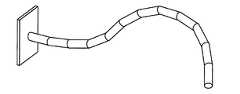
図1A〜図1Cに示す一実施形態による多関節のロボティックプローブ10は、本質的に2つの同心の機構、外側の機構および内側の機構であり、そのそれぞれは、操作可能な機構として見ることができる。図1A〜図1Cは、プローブ10の種々の実施形態の動作の仕方の概念を示す。図1Aを参照すると、内側の機構は、第1の機構、内側コアまたは内側コア機構12と呼ばれる。外側の機構は、第2の機構、外側スリーブまたは外側スリーブ機構14と呼ばれる。各機構は、剛直としなやかの間で交互することができる。剛直なモードまたは剛直な状態では、機構は、当然剛直である。しなやかなモードまたは状態では、機構は、非常に柔軟であり、したがってその周囲の形状を呈し、または新しい形をとることができる。本明細書で用いられる場合、用語「しなやかな(limp)」は、重力および機構の環境の形状に応じた特定の構成を受動的に呈する構造を示すのではなく、むしろ、本出願に記載の「しなやかな」構造は、デバイスの操作者によって望まれるポジションおよび構成を呈することができ、したがって、弛緩し、受動的であるのではなく、関節でつながれ、制御されることに留意されたい。Overview of an Articulated Robotic Probe An articulated
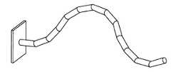
このプローブ10に関しては、ある機構がしなやかになり始め、他の機構が剛直になり始める。説明のために、図1A中のステップ1に見られるように、外側スリーブ14が剛直であり、内側コア12がしなやかであると仮定する。ここで、図1Aのステップ2に示されるように、内側コア12は、後述するフィード機構16によって前方に押される上に、その「ヘッド」または遠位端が操作される。次に、内側コア12が、剛直になるようにされ、外側スリーブ14がしなやかにされる。次いで、図1Aのステップ3に見られるように、外側スリーブ14が内側コア12に追い付き、または内側コア12と同一の広がりを持つまで、外側スリーブ14が、前方に押される。次に、外側スリーブ14が、剛直にされ、内側コア12がしなやかになり、次いで手順が繰り返される。この手法の一変更例は、外側スリーブ14も同様に操作可能にさせることである。図1Bに、そのようなデバイスの動作を示す。図1Bでは、各機構が、他方に追い付き、次いであるリンクを向こうに前進させることができることが分かる。一実施形態によれば、外側スリーブ14は操作可能であるが、内側コア12は操作可能ではない。図1Cに、そのようなデバイスの動作を示す。 With respect to the
医学的応用では、プローブ10が所望の位置に到着すると、操作者、典型的には外科医は、様々な診断法および/または投薬手技を行うように、外側スリーブ14、内側コア12、または外側スリーブ14と内側コア12の間に形成されたチャンネルのうちの1つ以上のチャンネルを通じて1つ以上のツールを摺動することができる。外科手術などの臨床処置に加えて、プローブ10は、エンジンの検査、修理、もしくは改造、タンクの検査および修理、スパイ行為または監視の応用、爆弾処理、潜水艦の区画室または核兵器などのきつく閉じ込められた空間内での検査または修理、建物の検査などの構造物の検査、有害廃棄物の浄化、炭疽菌回収などの生体試料の回収、ならびにこれらの組み合わせが含まれる多数の用途に使用することができるが、これらに限定されない。明らかに、本開示のデバイスは、より幅広い様々な用途を有し、任意の特定の用途に限定されるととらえるべきではない。 In medical applications, once the
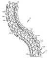
内側コア12および/または外側スリーブ14は、操作可能であり、内側コア12および側スリーブ14は、剛直としなやかの両方にそれぞれなすことができ、プローブ10が、3次元中のどこかへ駆動することを可能にする。プローブ10は、その以前の構成を「記憶する」ことができ、このため、プローブ10は、人間の患者などの患者の体内の空洞内空間などの3次元体積中のどこかへ行くことができる。図2A〜図2Bは、プローブ10による想定できる様々な構成の例を示す。 The
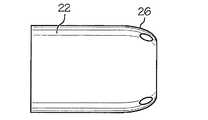
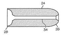
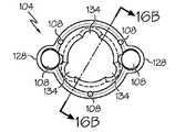
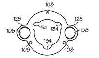
図3A〜図3Dならびに図4Aおよび図4Bに見られるように、一実施形態によれば、外側スリーブ14および内側コア12は、それぞれ、同心の複数の円筒、リンク22、24からそれぞれ構成することができるが、他の形状のリンク、例えば犬の骨の構成(図示せず)が使用されてもよく、ならびに同心のではないタイプのリンク、例えば、数多くある中でも骨格構成が使用されてもよい。リンク22、24の端部は平坦ではないが、代わりに一端26が「外側」または凸状の半球であり、他端28が「内側」または凹状の半球であり、両者は典型的には同様の曲率半径を有する。外側スリーブ14のリンク22、すなわちリンクは、あるリンクの凹状の端部28が、隣接したリンクの凸状の端部26に嵌め合わさるように「鎖状の」連続である。同様に、内側コア12のリンク24、すなわちリンクが、「鎖状の」連続である。その結果は、動学的見地から球のようなジョイントである。本実施形態では、各リンクは、隣接したリンクのヘッド上で回転することができ、任意の方向に約10〜20度の可動域を有する球面のジョイントとして働くが、他の可動域も可能であり、潜在的な利点である。一実施形態によれば、リンク22は、ケーブル、または細長いツールなどの細長いデバイスを制御するために内部を通じて延びる複数のチャンネル30を有する。 As seen in FIGS. 3A-3D and FIGS. 4A and 4B, according to one embodiment, the
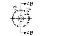
外側スリーブ14および内側コア12のいずれかまたは両方のヘッド(すなわち、遠位リンク)が、例えば、互いに120°で取り付けられる3本のケーブルを用いて操作可能である。図3A〜図3Dに見られるように、ケーブルがそれぞれ通過する3つの小さい円筒形のチャンネル30、32がある。図4Aおよび図4Bに示すデバイスのバージョンでは、内側リンク24は、ただ1本のケーブルを有し、この場合には、その中心を通るただ1つの穴34がある。 The head (ie, the distal link) of either or both the
上記の実施形態は、伝導性ワイヤもしくは非伝導性ワイヤ、または他のフレキシブルな糸状の構造などのケーブルを利用するが、個々のリンクの間に位置する小型の空気ピストンもしくは油圧ピストン、または他の機械的リンク機構などのしなやかな要素を操る代替手段が、本発明の概念の範囲から外れることなく用いることができることが理解されよう。 The above embodiments utilize cables such as conducting or non-conducting wires, or other flexible thread-like structures, but small air or hydraulic pistons located between individual links, or other It will be appreciated that alternative means of manipulating compliant elements such as mechanical linkages can be used without departing from the scope of the inventive concept.
リンク、したがってプローブ10は、プラスチックまたは他の磁気共鳴イメージングに適合する材料が含まれるほとんど任意の材料から作製することができる。外側スリーブ14は、典型的には5mmよりも大きい広範囲にわたる直径をとることができる。同様に、内側コア12は、外側スリーブ14の直径よりも小さく典型的には3mmより大きい広範囲にわたる直径をとることができる。リンクの総数は、大きい範囲にわたって変更することができるが、典型的には10個のリンクよりも多い。 The link, and hence the
述べた通り、内側コア12および外側スリーブ14は、ケーブルまたは他のフレキシブルな糸構造を用いて剛直またはしなやかにすることができる。一実施形態では、外側スリーブ14は、3本のケーブル上に張りめぐらされたリンク22のセットからなる。3本のケーブルは、典型的には120度離れており、任意の方向に操作することが可能である。プローブ10の曲率半径は、リンク22の長さ、ならびに嵌め合うリンク22の端部同士の間の嵌め合いの寸法が含まれるいくつかの要因に依存している。ケーブルが、外側スリーブ14の後部に向かって引っ張られるとき、リンク22は、互いに向かって引っ張られる。引張力が増加するとき、隣接したリンク22同士の間の摩擦力は、外側スリーブ14全体が堅くなる(すなわち、剛直なモードに入る)まで増加する。引張力を緩めると、外側スリーブ14はしなやかになる。したがって、ケーブルは、それらのそれぞれの張力組立体(例えば、モータにより駆動されるプーリ)と共に、ロックデバイスを形成する。張力組立体は、張力組立体を制御する電子機器と共に、ケーブルにかかる張力を制御する手段を含む。外側スリーブ14が、内側コア12の前方の1リンクに配置され、内側コア12が剛直なとき、外側スリーブ14の遠位リンクは、3本のケーブルのうちの1つ以上を引っ張ることによって向けることができる。ケーブルの前進または後退に加えて、各ケーブルに及ぼされる引張力の大きさは、監視または制御することができる。3本のケーブルを同じ大きさで引っ張ることによって、外側スリーブ14は、その形状を変化させずに剛直になる。 As stated, the
内側コア12は、外側スリーブ14のように、リンクのセットからなる。一実施形態によれば、外側スリーブ14とは対照的に、内側コア12は、操作機能を必要としない(しかし、適宜有してもよい)。内側コア12は、剛直なモードからしなやかなモードへ、および逆に変更する能力を必要としない。したがって、内側コア12が操作可能であることを必要としない実施形態では、内側コア12のリンクは、ただ1本のケーブル上に張りめぐらされてもよく、それによってプローブ10の全径の減少を可能にする。 The
フィード機構の概要
上述のように、フィード機構16は、プローブ10を制御するために使用され得る。図5Aおよび図5Bに示されるフィード機構16のあるタイプは、それぞれ、プローブ10を患者の食道、腹膜腔、心膜腔、または別の内部空間などの関心の領域に挿入およびそこから後退させる。フィーダ16は、2つの移動可能なカートを有する。第1の固定トレイ43で搬送される第1のカート42は、外側スリーブ14を前進および後退させる一方、第2の固定トレイ45で搬送される第2のカート44は、内側コア12を前進および後退させる。各カート42、44、したがって内側コア12および外側スリーブ14の各々は、それぞれ、別個のリニアアクチュエータ46、48によって独立して駆動される。リニアアクチュエータ46、48は、知られているようにポジション制御に用いられるシャフトエンコーダ(図示せず)を搬送することができる。代替としてまたは加えて、モータ電流が、ポジションを制御するために使用されるケーブルの張力の値を決定するために監視されてもよい。ケーブルの張力が、ロードセルなどの1つ以上のセンサを用いて監視されてもよい。多数のポジショニングセンサおよび他のセンサが、ケーブルの張力に関連した情報、カートのポジション、プローブの向きおよび構成、ならびに他のシステムのパラメータを供給するために備えられてもよい。典型的なセンサには、光学センサ、ホール効果センサなどの磁気センサ、加速度計、歪みゲージ、および機械スイッチなどの力センサおよび圧力センサ、ならびにこれらの組み合わせが含まれるが、これらに限定されない。1つ以上のセンサが、フィード機構16、内側コア12、および外側スリーブ14を含む複数の位置に配置されてもよいが、これらに限定されない。Overview of Feed Mechanism As mentioned above, the
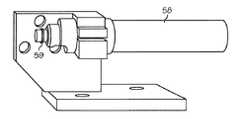
カート42、44の各々は、内側コア12および外側スリーブ14のケーブルを制御するのに必要な1つ以上のモータを搬送する。例えば、図6および図7に見られるように、カート42は、外側スリーブ14のケーブル54,55,56に対する張力を制御するモータ50、51、52を搬送する。図8に示すように、第2のカート44は、内側コア12のケーブル59への張力を制御するモータ58を有する。モータ50、51、52および58の各々は、知られているようにポジション制御に用いられるシャフトエンコーダ(図示せず)を備えることができる。内側コア12が操作可能である一実施形態では、内側コア12は、(例えば、2本以上のケーブルをぴんと張るために)2つ以上のモータ、または別のケーブルの張力機構を必要とする。 Each
図9は、制御システムの一実施形態の構成要素、およびこれらの構成要素間の情報の流れを示す構成図である。フィード機構16は、バス変換モジュール64を介して制御コンピュータ62に接続される。フィード機構16から出て行くデータは、USBに変換するためにモジュール64に入力され、次いでコンピュータ62にあるUSBポート66に入力される。制御ソフトウェア68へ入ってくるデータには、フィード機構16内の各ケーブルに関連したモータ電流データ、モータエンコーダデータ、および/またはケーブルの張力データが含まれ得る。代替としてまたは加えて、制御ソフトウェア68へ入ってくるデータには、フィード機構16、内側コア12、または外側スリーブ14内に位置する1つ以上のセンサからのデータが含まれ得る。ジョイスティックデータ(ポジションデータ)をジョイスティック70から受信することもできる。モニタ72は、外側スリーブ14および/または内側コア12の遠位端に取り付けたカメラからの映像データに応答することができて、プローブ10の遠位端のポジションに関するユーザへの視覚フィードバックを与える。制御ソフトウェア68は、モータ電流制限命令およびモータポジション命令を出力することができ、モータ電流制限命令およびモータポジション命令はフィード機構16へ入力される。 FIG. 9 is a block diagram showing the components of one embodiment of the control system and the flow of information between these components. The
内側コアおよび外側スリーブ
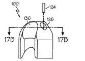
図10A〜図11Bは、内側コア12および外側スリーブ14を備える関節プローブ10の一実施形態を示す。内側コア12は、複数の内側リンク100(好ましくは少なくとも3つ、いくつかの実施形態では50個以上)を有する。外側スリーブ14は、複数の外側リンク104(好ましくは少なくとも3つ、いくつかの実施形態では、40個以上)を有する。Inner Core and Outer Sleeve FIGS. 10A-11B illustrate one embodiment of an articulating
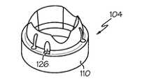
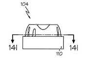
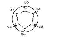
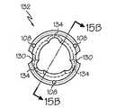
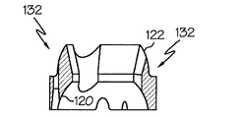
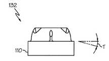
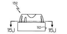
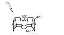
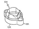
外側リンクに関しては、図14A〜図16Jは、そのような外側リンク104、132の現在好ましい実施形態の様々な図を示す。外側リンクのこれらの実施形態は、上記の概要で述べたものに類似する。しかし、これらの実施形態は、いくつかの重要な態様において上述のものとは異なると共に、互いに異なる。外側リンク104、132の本実施形態は、図11Aに示すような独特な外側スリーブ14を形成するために組み合されてもよい。詳細には、図16A〜図16Kは、ツール側部ポート128を備える外側リンク104の様々な図を示す。ツール側部ポート128は、ツールを受容および案内するために使用することができる。図15A〜図15Jは、つなぎ外側リンク132の様々な図を示す。図11Aに示すように、複数のつなぎ外側リンク132は、ツール側部ポート128を備える外側リンク104に隣接して配置することができる。つなぎ外側リンク132は、外側リンク104のツール側部ポート128にツールなどの細長い部材を収容しおよび送り込む1つ以上の凹所130を有することができる。例えば、好ましくは、外側リンク104、132の内径は、0.10〜2.00インチの範囲内であり、より好ましくは、内径は約0.394インチである。好ましくは、外側リンク104、132の外径は、0.20〜3.00インチの範囲内であり、より好ましくは、外径は約0.669インチである。外側リンク104、132は、例えば、金属、プラスチック、ガラス、カーボンファイバなどのうちの少なくとも1つから構成することができる。特定の実施形態では、外側リンク104、132は、例えば、ポリフェニルサルフォン(例えば、Radel(登録商標)R−5100)から構成される。 With respect to the outer links, FIGS. 14A-16J show various views of a presently preferred embodiment of such
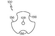
内側リンク100に関して、図17A〜図17Iは、現在好ましい実施形態の様々な図を示す。これらの内側リンク100は、上記の概要で述べたものに類似する。しかし、これらの内側リンク100は、いくつかの重要な態様において異なる。好ましくは、内側リンク100の長さは0.01〜2.00インチの範囲内であり、より好ましくは内側リンク100の長さは0.353インチである。好ましくは、内側リンクの外径は0.10〜2.00インチの範囲内であり、より好ましくは、内径は0.354インチである。内側リンク100は、例えば、金属、プラスチック、ガラス、カーボンファイバなどのうちの少なくとも1つから構成されてもよい。特定の実施形態では、内側リンク100は、埋め込まれたガラス繊維(30重量%)を有するプラスチックから構成される。 With respect to the
例えば、図10A〜図13Bに示すように、内側リンク100は、最大枢動角度によって互いに対して枢動するように構成され、外側リンク104は、最大枢動角度によって互いに対して枢動するように構成される。好ましくは、内側リンク100の最大の枢動角度は、外側リンク104の最大の枢動角度以上である。この枢動関係を考慮すると、リンク100、104が、関節プローブ10の屈曲の制限、リンク100、104内に配置できる細長い部材の挟み、および細長い部材の前進および後退に関して起こり得る問題などの1つ以上の望ましくない条件を避けるように構成されることが大切であり得る。 For example, as shown in FIGS. 10A-13B, the
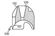
複数の内側リンク100および/または外側リンク104の各々は、細長い部材を受け入れるための1つ以上のチャンネル108を有してもよい。代替としてまたは加えて、内側リンク100および外側リンク104における嵌め合う凹所が、内側コア12と外側スリーブ14の間に1つ以上のチャンネルを作り出してもよい。細長い部材は、ツール、内側ケーブル102、外側ケーブル106、または内側コア12のいずれか1つであってもよい。典型的な細長いツールには、はさみ、外科用メス、および他の切断用ツール、組織把持装置などの把持装置、組織切除要素、電気メス、および凝固要素などのエネルギー供給要素、光ファイバカメラなどのキャンバ、加熱要素、冷却要素、薬物送達デバイス、およびこれらの組み合わせが含まれ得るが、それらに限定されない。概要で述べたように、ツールは、様々な動作を行うために使用することができ、1つ以上のケーブルは、外側スリーブ14の外側リンク104および内側コア12の内側リンク100を制御するために使用することができる。チャンネル108は、リンク100、104から隣接したリンク100、104へ半連続通路を形成するように構成され、細長い部材の受け入れを容易にするためにライナを含むことができる。図14Gに示すように、チャンネル108は、円周状フレアを有してもよい。円周状フレアは、チャンネル108内に細長い部材を挟むのを防ぎ、複数のリンク100、104の回転を容易にさせつつ、プローブ10を通じての細長い部材の前進または後退により生じ得る何らかの困難をかなり低減させる。さらに、内側リンク100および/または外側リンク104のチャンネル108は、リンク100、104からリンク100、104への半連続通路を実現するために先細りであってもよい。 Each of the plurality of
一実施形態によれば、内側リンク100および/または外側リンク104の各々におけるチャンネル108は、内側リンク100および/または外側リンク104が、最大の枢動角度によって枢動することを可能にしつつ、細長い部材を受け入れるためにリンク100のチャンネル108とリンク104のチャンネル108の間に実質的に連続な面を用意するのに十分な量で先細りである。より好ましくは、チャンネル108の開口および/または出口は、先細りであり得る。チャンネル108の先細りの開口および出口は、チャンネル108内に細長い部材を挟むのを防ぎ、プローブ10を通じての細長い部材の前進または後退により生じ得る何らかの困難をかなり低減させる。加えて、先細りの開口は、プローブ10の曲率半径に相関している。一実施形態によれば、チャンネル108の先細りは、最大の枢動角度の約2倍である。例えば、先細りは約26度とすることができ、最大の枢動角度は約13度とすることができる。好ましくは、チャンネル108の先細りは、13度以上の枢動角度を収容することができる。要するに、先細りのチャンネル108は、細長い部材を受け入れるためにリンク100のチャンネル108とリンク104のチャンネル108の間で実質的に連続な面を用意するように構成される。 According to one embodiment, the
内側コア12の内側リンク100は、図13A〜図13B、および図17A〜図17Iに示すように、中心軸の近くに配置され、内側ケーブル102(細長い部材)を受け入れるように構成されるチャンネル108を有してもよい。内側リンク100内のチャンネル108は、広がった開口を有することができる。一実施形態によれば、広がった開口は、内側リンク100の中心軸に対して中心を外れて配置される。広がった開口を中心を外して配置することによって、内側コア12の回転または起こり得る並進変位の任意の他の形態により、内側コア12の枢動点が変わることができるとき、内側ケーブル102の枢動点がより容易に変わることを可能にする。好ましくは、内側リンク100の複数のチャンネル108の直径は、内側ケーブル102の直径より大きく、それによって内側リンク100がねじれおよび鋸歯状の発生を減少させる。例えば、好ましくは、チャンネル108が0.003〜0.500インチの範囲内(より好ましくは約0.043インチ)の直径を有する場合、内側ケーブル102の直径は、0.002〜1.000インチの範囲内(より好ましくは約0.037インチ)であることが好ましい。ねじれおよび鋸歯状を減少させるように内側ケーブル102の直径、および内側リンク100のチャンネル108を構成することによって、挟みの可能性、または細長い部材の前進および後退に関連した困難は、やはりかなり減少する。したがって、内側リンク100のチャンネル108は、内側ケーブル102のためにリンク100同士の間に実質的に連続な面を用意する。 The
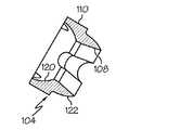
例えば、図12Aに示すように、外側スリーブ14の外側リンク104は、細長い部材を受け入れるために内部に形成されるチャンネル108を有することもできる。この特定の実施形態では、細長い部材は、複数の内側リンク100を備える内側コア12であり得る。チャンネル108は、複数の外側リンク104を備え、それぞれが、広がった開口を有する。図12Aに示すように、複数のリンク104の各々における広がった開口は、内側コア12を受け入れるためにリンク104同士の間に実質的に連続な面を用意する。外側リンク104のチャンネル108は、内側コア12が、最大枢動角度によって枢動することを可能にしつつ、内側コア12のためにチャンネル108同士の間に実質的に連続な面を用意するのに十分な量でやはり先細りである。チャンネル108の先細りは、内側リンク100の屈曲を可能にもする。好ましくは、内側リンク100の内側の屈曲は、13度以上であり得る。したがって、外側リンク104のチャンネル108は、内側コア12を受け入れるためにリンク104同士の間に実質的に連続な面を用意する。 For example, as shown in FIG. 12A, the
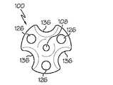
図14A〜図16Kに示すように、複数のチャンネル108は、外側リンク104の外面の近くに配置することもできる。一実施形態によれば、3つのチャンネル108が、外側スリーブ14を構成する1つ以上の外側リンク104の円周の周りに互いから約120度で配置される。外側リンク104のチャンネル108は、外側スリーブ14を制御するために外側ケーブル104の形態の細長い部材を受け入れるように構成される。好ましくは、複数の外側ケーブル106の直径は、外側リンク104の複数のチャンネル108の直径未満であり、それによって外側リンク104のねじれおよび鋸歯状の発生を減少させる。一実施形態によれば、複数の外側ケーブル106の直径は、0.002〜1.000インチの範囲内とすることができる。一実施形態では、複数の外側ケーブル106の直径は、0.027インチである。外側ケーブル106を受け入れるための外側リンク104ごとの複数のチャンネル108の直径は、0.003〜0.500インチの範囲内とすることができる。特定の実施形態では、外側リンク104ごとの複数のチャンネル108の直径は、約0.035インチである。ねじれおよび鋸歯状を減少させるように複数の外側ケーブル106の直径、および外側リンク104のチャンネル108を構成することによって、挟みの可能性、または細長い部材の前進および後退に関連した困難は、やはりかなり減少する。したがって、外側リンク104のチャンネル108は、複数のケーブル106のためにリンク104同士の間に実質的に連続な面を用意する。 As shown in FIGS. 14A-16K, the plurality of
内側リンク100と外側リンク104の組み合わせは、細長い部材を受け入れるためのチャンネル108を設けるように構成することもできる。図14A〜図14Iを参照すると、外側リンク104の内面は、ツールの形態の細長い部材を受け入れるためのチャンネル108の一方の半分を形成する広がったくぼみ134を有してもよい。図17A〜図17Iに示すように、チャンネル108の他の半分は、内側リンク100の外面上の広がったくぼみ136によって形成される。内側リンク100の広がったくぼみ136および外側リンク104の広がったくぼみ134によって形成されるチャンネル108は、1つ以上のツールのためにリンク100、104の間に実質的に連続な面を用意する。 The combination of the
図15A〜図16Kに示す外側リンク104および132は、ツール、ケーブル、または他の細長いデバイスの形態で細長い部材を受け入れるように共に構成することができる。図11Aおよび図16A〜図16Kを参照すると、外側リンク104のチャンネル108は、ツール側部ポート128によって形成することができる。ツール側部ポート128は、外側リンク104の外周から広がり、ツール、ケーブル、または他の細長いデバイスを受け入れるようにチャンネル108が形成される。図11Aに示すように、つなぎ外側リンク132が、プローブ10の長さに沿って、外側リンク104とツール側部ポート128を備える外側リンク104との間に配置される。一実施形態によれば、図15A〜図15Jに示すように、つなぎ外側リンク132は、ツール側部ポート128を有する外側リンク104にツールを収容しおよび送り込む1つ以上の凹所130を有する。したがって、プローブ10の周囲のほぼ外側で使用するように構成されるツールが、ツール側部ポート128によって形成されるチャンネル108、およびつなぎ外側リンク132の凹所130によって受け入れられ得る。ツール側部ポート128によって形成されるチャンネル108、および凹所130は、1つ以上の細長いデバイスのために外側リンク104、132の間に実質的に連続な面を用意する。 The
関節プローブ10の曲率半径は、内側リンク100および外側リンク104の枢動角度に依存し得る。図10A〜図12Bおよび図14A〜Iを参照すると、外側スリーブ14は、外側に延びるフランジ110を有する複数の外側リンク104を含んでもよい。フランジ110は、互いに対して外側リンク104の枢動角度を制御するように構成される。したがって、フランジ110の特徴は、実現され得る関節プローブ10の曲率半径に影響を及ぼす。 The radius of curvature of the
一実施形態によれば、フランジ110の幾何学的形状は、外側リンク104の各々の間で可能な枢動の程度を決定する。図14D〜図14Eを参照すると、フランジ110は、外側リンク104の第1の中心軸に対して半径方向外側に延びる第1の係合面112および第2の係合面114を有することができる。フランジ110は、第1の外側リンク104の第1の係合面112および第2の外側リンクの第2の係合面114が、互いに接触するまで、外側リンク104が、外側の最大の枢動角度によって互いに対しておよびプローブの中心軸に関して枢動することを可能にするように構成される。一実施形態によれば、第1の係合面112および第2の係合面114は、外側リンク104の中心軸に垂直な線に関して先細りである。図14Eを参照すると、特定の一実施形態では、第1の係合面112は、約6.5度先細りになり、第2の係合面114は、約6.5度先細りになる。本実施形態によれば、外側の最大の枢動角度は、約13度以下である。代替実施形態では、第1の係合面112および第2の係合面114の先細りは、最大の枢動角度が、13度より大きい、または13度未満であるように構成されてもよい。好ましくは、フランジ110の幾何学的形状は、関節プローブ10の曲率半径が、10〜600mmの範囲内であるように構成される。したがってフランジ110の幾何学的形状は、外側リンク104の最大の枢動角度を設定するように用いることができ、これは、関節プローブ10の曲率半径の範囲に影響を及ぼす。 According to one embodiment, the geometry of the
リンク100、104、132は、第1のリンク100と第2のリンク104の間に作用する不規則または望ましくない力(例えば、不規則または望ましくない摩擦係合力)の発生を減少させるように構成され得る。例えば、図14B、図14H、図15B、図15C、図15I、図16B、図16C、図16J、図17C、図17D、図17Hに示すように、複数の内側リンク100および外側リンク104は、第1の凹部120、および第1の凸部122を含むことができる。第1のリンク100、104の凸部122は、第2のリンク100、104の対応する凹部120に枢動可能に係合することができる。特定の実施形態によれば、第1のリンク100、104、凸部122は、第2のリンク100、104、凹部120の曲率半径以下の曲率半径を有する。リンク100、104は、共に連結されて、内側コア12および外側スリーブ14を形成することができる。(凹部120が、対応する凸部122に枢動可能に係合する)リンク100、104の構成によって、内側コア12および外側スリーブ14が、広い可動域で枢動し、関節プローブ10の効率的な動作を妨げる可能性があるリンク100、104の間の不規則または望ましくない摩擦力または他の力の発生を減少させることが可能である。 The
上記で明らかにしたように、内側コア12および外側スリーブ14の様々な特徴の物理的特性は、様々な形で関節プローブ10の特性および性能に悪影響を及ぼす。一実施形態によれば、外側リンク104の1つ以上のチャンネルの幾何学的寸法は、外側リンク104の1つ以上のパラメータ数学的に関連している。これらのパラメータには、外側リンク104の端部の半径、外側リンク104の直径、外側リンク104d同士間の枢動角度、チャンネルの平均直径などのチャンネルの直径、外側リンク104の中心軸からのチャンネルの距離などのチャンネルの位置が含まれ得る。 As revealed above, the physical characteristics of the various features of the
あるリンクの他のリンクに対する滑らかな継ぎ目を促進し、隣接したリンクの間の不規則な摩擦係合などの望ましくない嵌め合い力を防ぐようにリンクを形成することが有利であり得る。次に、図17A、図17B、図17D〜図17F、図17Iおよび図18を参照して、関節プローブ10用のリンク100、104を生産する方法を説明する。ステップ210では、リンク100、104が、関節プローブ10内の隣接したリンク100、104に係合するように構成される少なくとも1つの係合面を形成することを含めて、鋳造装置において成型される。ステップ212では、リンク100、104は、関節プローブ10内の隣接したリンク100、104に係合しないリンク100、104の排出面126に少なくとも1つの排出ピン124を押圧する(図17E参照)ことによって、鋳造装置から排出される。図17A、図17B、図17D〜図17E、および図17Iに示すように、一実施形態によれば、排出面126は、リンク100、104中の凹所に位置する。リンク100、104上に排出面126を合理的に配置することにより、隣接したリンク間の嵌め合う面から離れて排出ピンの狂いを配置することなどによって、排出面126が、あるリンク100、104と別のリンクの相互作用に影響を及ぼさないことを確実にする。したがって、上記の手順は、各リンク100、104が、別のリンク100、104に対して滑らかに関節でつながることを確実にする。 It may be advantageous to form a link so as to promote a smooth seam to one link to another and to prevent undesirable mating forces such as irregular frictional engagement between adjacent links. Next, a method for producing the
ケーブル
上記の概要で述べたように、1つ以上のケーブルが、外側スリーブ14の外側リンク104、および内側コア12の内側リンク100を制御するため使用することができる。以下、ケーブル構成のさらなる例を説明する。これらの構成では、図12Bに示すように、複数の外側ケーブル106は、複数の外側リンク104を通じて延びることができる。外側ケーブル106は、外側スリーブ14を制御(例えば、操作、および柔軟と剛直の間で移行)するように構成される。一実施形態では、複数の外側ケーブル106の各々は、ほぼ同じ引張り強度および/またはほぼ同じ断面積を有する。Cable As described in the above summary, one or more cables can be used to control the
図13A〜図13Bに示すように、内側ケーブル102は、複数の内側リンク100を通じて延びる。内側ケーブル102は、内側コア12を制御(例えば、柔軟と剛直の間で移行)するように構成される。一実施形態では、内側ケーブル102の引張り強度および/または断面積は、複数の外側ケーブル106の引張り強度および/または断面積に関連している。 As shown in FIGS. 13A-13B, the
内側ケーブル102の引張り強度および/または断面積と複数の外側ケーブル106の引張り強度および/または断面積との間の関係により、関節プローブ10の効率的な動きおよび動作を実現する。引張り強度に関しては、内側ケーブル102は、個々の外側ケーブル106の各々より大きい引張り強度を有し得る。いくつかの実施形態では、内側ケーブル102の引張り強度は、複数の外側ケーブル106の合成引張り強度にほぼ等しい。いくつかの実施形態では、複数の外側ケーブル106の各々の引張り強度は、内側ケーブル102の引張り強度の約1/Nであり、ただし、Nは、外側ケーブル106の本数である。例えば、内側ケーブル102の引張り強度および複数の外側ケーブル106の合成引張り強度は、2〜500lbの範囲内であり得、いくつかの実施形態では、約30lbである。 The relationship between the tensile strength and / or cross-sectional area of the
断面積に関しては、複数の外側ケーブル106の各々の断面積は、内側ケーブル102の断面積の約1/Nであり得、ただし、Nは、外側ケーブルの本数である。この関係は、排他的なものではないが、ケーブル102、106が同じ材料から形成される構成で、および/またはプローブ10の直径が最小であるとき、特に重要である。 Regarding the cross-sectional area, the cross-sectional area of each of the plurality of
内側ケーブル102および外側ケーブル106を形成する材料は、ケーブルの構成に影響を及ぼし得る。内側ケーブル102および複数の外側ケーブル106は、同じ材料で構成されてもよく、これは、いくつかの実施形態では、鋼鉄、ポリエチレン(UHMW−超高分子量)、プラスチック、ナイロン、およびフルオロカーボンのうちの少なくとも1つとすることができ、いくつかの実施形態では、鋼鉄がより好ましい。内側ケーブル102および複数の外側ケーブル106は、単繊維または編む技法によって形成することができる。しかし、所望の引張り強度の関係は、内側ケーブル102および外側ケーブル106に異なる材料を用いることによって実現することもできる。 The material forming the
要するに、内側コア12および外側スリーブ14を制御するために用いられる内側ケーブル102および外側ケーブル106は、様々な特徴を有し得る。これらの特徴には、引張り強度、断面積、およびケーブル102、106の組成が含まれ得るが、それに限定されるものではない。所望の特徴、および内側ケーブル102および外側ケーブル106に関する関係に基づいて、ケーブルの構成によって、関節プローブ10の安定性および他の性能パラメータを決定する。 In short, the
本デバイスおよび方法の好ましい実施形態を、それらが開発された環境に関連して説明してきたが、それらは、本発明の概念の原理の例示に過ぎない。上記の組立体の変形または組み合わせ、本発明を実施するための他の実施形態、構成、および方法、ならびに当業者に明らかな本発明の概念の態様の変更例は、特許請求の範囲の範囲内にあることが意図される。加えて、本出願が、特定の順序で挙げた方法または手順のステップを有する場合、いくつかのステップが実行される順序を変更することが可能であり得、またはある状況では適切でさえあり得、そのような順序の特定性が請求項において明示的に定められない限り、以下に本明細書に記載したこの方法または手順の請求項の特定のステップは、順序が特定されていると解釈されないものとする。 Although preferred embodiments of the devices and methods have been described in the context of the environment in which they were developed, they are merely illustrative of the principles of the inventive concept. Variations or combinations of the above-described assemblies, other embodiments, configurations and methods for practicing the present invention, and variations of aspects of the inventive concept apparent to those skilled in the art are within the scope of the claims. It is intended to be In addition, if the application has method or procedural steps listed in a particular order, it may be possible to change the order in which some steps are performed, or even appropriate in certain circumstances. Unless specificity of such a sequence is explicitly set forth in the claims, the specific steps of the claims of this method or procedure described herein below are not to be construed as specific Shall.
Claims (9)
Translated fromJapanese複数の内側リンクを有する内側コアと、
前記複数の内側リンクを通じて延びると共に、前記内側コアを制御するように構成される一つの内側ケーブルと、
複数の外側リンクを有する外側スリーブと、
前記複数の外側リンクを通じて延びると共に、前記外側スリーブを制御するように構成される複数の外側ケーブルと
を備え、
前記内側コアの内側リンクを通じて延びる前記内側ケーブルが、個々の前記外側リンクを通じて延びる前記外側ケーブルの各々より大きい引張り強度を有することを特徴とする関節プローブ。An articulation probe having at least a portion configured to be controllably rigid and flexible;
An inner core having a plurality of inner links;
An inner cable extending through the plurality of inner links and configured to control the inner core;
An outer sleeve having a plurality of outer links;
A plurality of outer cables extending through the plurality of outer links and configured to control the outer sleeve;
The joint probe, wherein the inner cables extending through the inner links of the inner core have a greater tensile strength than each of the outer cables extending through the individual outer links.
Applications Claiming Priority (10)
| Application Number | Priority Date | Filing Date | Title |
|---|---|---|---|
| US40603210P | 2010-10-22 | 2010-10-22 | |
| US61/406,032 | 2010-10-22 | ||
| US41273310P | 2010-11-11 | 2010-11-11 | |
| US61/412,733 | 2010-11-11 | ||
| US201161472344P | 2011-04-06 | 2011-04-06 | |
| US61/472,344 | 2011-04-06 | ||
| US201161492578P | 2011-06-02 | 2011-06-02 | |
| US61/492,578 | 2011-06-02 | ||
| US201161534032P | 2011-09-13 | 2011-09-13 | |
| US61/534,032 | 2011-09-13 |
Related Parent Applications (1)
| Application Number | Title | Priority Date | Filing Date |
|---|---|---|---|
| JP2013535114ADivisionJP5711380B2 (en) | 2010-10-22 | 2011-10-21 | Articulated robotic probe |
Publications (2)
| Publication Number | Publication Date |
|---|---|
| JP2015120034A JP2015120034A (en) | 2015-07-02 |
| JP5864002B2true JP5864002B2 (en) | 2016-02-17 |
Family
ID=45975912
Family Applications (2)
| Application Number | Title | Priority Date | Filing Date |
|---|---|---|---|
| JP2013535114AExpired - Fee RelatedJP5711380B2 (en) | 2010-10-22 | 2011-10-21 | Articulated robotic probe |
| JP2015043180AExpired - Fee RelatedJP5864002B2 (en) | 2010-10-22 | 2015-03-05 | Joint probe |
Family Applications Before (1)
| Application Number | Title | Priority Date | Filing Date |
|---|---|---|---|
| JP2013535114AExpired - Fee RelatedJP5711380B2 (en) | 2010-10-22 | 2011-10-21 | Articulated robotic probe |
Country Status (6)
| Country | Link |
|---|---|
| US (3) | US8992421B2 (en) |
| EP (1) | EP2629655B1 (en) |
| JP (2) | JP5711380B2 (en) |
| AU (2) | AU2011316849B2 (en) |
| CA (1) | CA2815396A1 (en) |
| WO (1) | WO2012054829A2 (en) |
Families Citing this family (63)
| Publication number | Priority date | Publication date | Assignee | Title |
|---|---|---|---|---|
| EP3123922B1 (en)* | 2004-06-25 | 2019-11-27 | Carnegie Mellon University | Steerable, follow the leader device |
| WO2013096610A1 (en)* | 2011-12-21 | 2013-06-27 | Oyola Arnold E | Stabilizing apparatus for highly articulated probes with link arrangement, methods of formation thereof, and methods of use thereof |
| GB2500711A (en)* | 2012-03-30 | 2013-10-02 | Philip Michael Peter Beglan | Structure of changeable shape |
| FR2991221B1 (en)* | 2012-06-01 | 2015-02-27 | Aldebaran Robotics | VERTEBRAL COLUMN FOR HUMANOID ROBOT |
| US9144370B2 (en) | 2013-02-28 | 2015-09-29 | Canon Usa Inc. | Mechanical structure of articulated sheath |
| US9913695B2 (en) | 2013-05-02 | 2018-03-13 | Medrobotics Corporation | Robotic system including a cable interface assembly |
| WO2015042453A1 (en)* | 2013-09-20 | 2015-03-26 | Canon U.S.A., Inc. | Control apparatus for tendon-driven device |
| KR20160090344A (en) | 2013-11-27 | 2016-07-29 | 메드로보틱스 코포레이션 | Oral retraction devices and methods |
| CA2966131A1 (en)* | 2014-06-05 | 2015-12-10 | Medrobotics Corporation | Articulating robotic probes, systems and methods incorporating the same, and methods for performing surgical procedures |
| JP2018512967A (en)* | 2015-04-20 | 2018-05-24 | メドロボティクス コーポレイション | Articulated robotic probe, system and method for incorporating a probe, and method for performing a surgical procedure |
| EA201890455A1 (en)* | 2015-08-07 | 2018-09-28 | Аджой И. Сингх | PORTABLE DEVICE FOR TREATMENT OF ARTERY AND METHOD OF TREATING ARTERIA |
| JP7082052B2 (en) | 2015-09-03 | 2022-06-07 | ネプチューン メディカル インク. | A device for advancing the endoscope in the small intestine |
| US20180193608A1 (en)* | 2016-01-15 | 2018-07-12 | Cook Medical Technologies Llc | Modular medical guide wire assembly |
| US10434288B2 (en)* | 2016-01-15 | 2019-10-08 | Cook Medical Technologies Llc | Locking medical guide wire |
| KR102708262B1 (en) | 2016-02-05 | 2024-09-20 | 보드 오브 리전츠, 더 유니버시티 오브 텍사스 시스템 | The manipulatable intraruminal medical device |
| BR112018009251A2 (en) | 2016-02-05 | 2019-04-09 | Board Of Regents Of The University Of Texas System | surgical apparatus and customized main controller for a surgical apparatus |
| WO2017145340A1 (en)* | 2016-02-25 | 2017-08-31 | オリンパス株式会社 | Manipulator system and operating method therefor |
| WO2017145342A1 (en)* | 2016-02-25 | 2017-08-31 | オリンパス株式会社 | Manipulator system and operating method therefor |
| US10603047B2 (en) | 2016-05-23 | 2020-03-31 | Mako Surgical Corp. | Medical device for cutting bone |
| EP3500151A4 (en) | 2016-08-18 | 2020-03-25 | Neptune Medical Inc. | DEVICE AND METHOD FOR IMPROVED VISUALIZATION OF THE SMALL BOWEL |
| CN110290738A (en)* | 2017-02-13 | 2019-09-27 | 奥林巴斯株式会社 | Endoscope-use bending section |
| US11103992B2 (en) | 2017-02-28 | 2021-08-31 | Canon Kabushiki Kaisha | Apparatus of continuum robot |
| US11278366B2 (en) | 2017-04-27 | 2022-03-22 | Canon U.S.A., Inc. | Method for controlling a flexible manipulator |
| US11241245B2 (en)* | 2017-05-15 | 2022-02-08 | Boston Scientific Scimed, Inc. | Tissue deflecting devices and related methods of use |
| WO2018216117A1 (en) | 2017-05-23 | 2018-11-29 | オリンパス株式会社 | Flexible tube for medical use and flexible manipulator for medical use |
| US11007641B2 (en) | 2017-07-17 | 2021-05-18 | Canon U.S.A., Inc. | Continuum robot control methods and apparatus |
| JP7379321B2 (en) | 2017-07-20 | 2023-11-14 | ネプチューン メディカル インク. | Dynamically rigid overtube |
| US20200261171A1 (en) | 2017-11-06 | 2020-08-20 | Medrobotics Corporation | Robotic system with articulating probe and articulating camera |
| FR3073440B1 (en)* | 2017-11-16 | 2019-10-25 | Warein | INFLATABLE TUBE WITH VARIABLE GEOMETRY AND CONSTANT VOLUME, ROBOTIC ARM AND ROBOT |
| US20210052336A1 (en)* | 2018-01-05 | 2021-02-25 | Medrobotics Corporation | Robotically controlled surgical tool |
| US20210068615A1 (en)* | 2018-01-05 | 2021-03-11 | Medrobotics Corporation | Robotic surgical system |
| USD874655S1 (en) | 2018-01-05 | 2020-02-04 | Medrobotics Corporation | Positioning arm for articulating robotic surgical system |
| US20200352554A1 (en)* | 2018-01-05 | 2020-11-12 | Medrobotics Corporation | Robotic system |
| CN108272429B (en)* | 2018-02-09 | 2020-12-01 | 京东方科技集团股份有限公司 | Endoscope with a detachable handle |
| US10962345B2 (en)* | 2018-05-23 | 2021-03-30 | General Electric Company | Tool and method for inspecting an annular space of an engine |
| US11458641B2 (en)* | 2018-05-23 | 2022-10-04 | General Electric Company | Robotic arm assembly construction |
| US11305420B2 (en)* | 2018-05-31 | 2022-04-19 | Virginia Tech Intellectual Properties, Inc. | Articulated multi-link robotic tail systems and methods |
| US12059128B2 (en) | 2018-05-31 | 2024-08-13 | Neptune Medical Inc. | Device and method for enhanced visualization of the small intestine |
| CN112714658A (en) | 2018-07-19 | 2021-04-27 | 海王星医疗公司 | Dynamic rigidized composite medical structure |
| US11707819B2 (en)* | 2018-10-15 | 2023-07-25 | General Electric Company | Selectively flexible extension tool |
| US12194620B2 (en)* | 2018-10-15 | 2025-01-14 | Oliver Crisipin Robotics Limited | Selectively flexible extension tool |
| US10906173B2 (en)* | 2018-11-15 | 2021-02-02 | Zezhi Intellectual Property Service | Smart cabinet |
| US11702955B2 (en) | 2019-01-14 | 2023-07-18 | General Electric Company | Component repair system and method |
| CN109693246A (en)* | 2019-01-18 | 2019-04-30 | 哈尔滨工业大学 | Enhance the bridging arrangement of growth type soft robot rigidity |
| US11793392B2 (en) | 2019-04-17 | 2023-10-24 | Neptune Medical Inc. | External working channels |
| WO2020214221A1 (en) | 2019-04-17 | 2020-10-22 | Neptune Medical Inc. | Dynamically rigidizing composite medical structures |
| US12405187B2 (en) | 2019-10-04 | 2025-09-02 | General Electric Company | Insertion apparatus for use with rotary machines |
| US11692650B2 (en) | 2020-01-23 | 2023-07-04 | General Electric Company | Selectively flexible extension tool |
| US11752622B2 (en) | 2020-01-23 | 2023-09-12 | General Electric Company | Extension tool having a plurality of links |
| US11613003B2 (en) | 2020-01-24 | 2023-03-28 | General Electric Company | Line assembly for an extension tool having a plurality of links |
| US11371437B2 (en) | 2020-03-10 | 2022-06-28 | Oliver Crispin Robotics Limited | Insertion tool |
| US11571269B2 (en) | 2020-03-11 | 2023-02-07 | Verb Surgical Inc. | Surgeon disengagement detection during termination of teleoperation |
| CA3178444A1 (en) | 2020-03-30 | 2021-10-07 | Neptune Medical Inc. | Layered walls for rigidizing devices |
| EP3900650A1 (en)* | 2020-04-23 | 2021-10-27 | Microsure B.V. | Surgical robotic system comprising spherical wrist |
| US12091981B2 (en) | 2020-06-11 | 2024-09-17 | General Electric Company | Insertion tool and method |
| FR3118406B1 (en)* | 2020-12-28 | 2024-05-03 | Robocath | ROBOT CATHETER COMPRISING AT LEAST TWO ELONGATED FLEXIBLE MEDICAL INSTRUMENT TRANSLATION MODULES |
| US20220221706A1 (en)* | 2021-01-08 | 2022-07-14 | General Electric Company | Insertion tool |
| US12416800B2 (en) | 2021-01-08 | 2025-09-16 | General Electric Company | Insertion tool |
| KR20230133374A (en) | 2021-01-29 | 2023-09-19 | 넵튠 메디컬 인코포레이티드 | Device and method for preventing inadvertent movement of a dynamic stiffening device |
| JPWO2022176841A1 (en)* | 2021-02-18 | 2022-08-25 | ||
| US11654547B2 (en) | 2021-03-31 | 2023-05-23 | General Electric Company | Extension tool |
| KR20250003955A (en) | 2022-04-27 | 2025-01-07 | 넵튠 메디컬 인코포레이티드 | Sanitary outer covering for endoscope |
| US12330292B2 (en) | 2023-09-28 | 2025-06-17 | Neptune Medical Inc. | Telescoping robot |
Family Cites Families (161)
| Publication number | Priority date | Publication date | Assignee | Title |
|---|---|---|---|---|
| US2510198A (en)* | 1947-10-17 | 1950-06-06 | Earl B Tesmer | Flexible positioner |
| US3060972A (en) | 1957-08-22 | 1962-10-30 | Bausch & Lomb | Flexible tube structures |
| US3557780A (en) | 1967-04-20 | 1971-01-26 | Olympus Optical Co | Mechanism for controlling flexure of endoscope |
| US3583393A (en) | 1967-12-26 | 1971-06-08 | Olympus Optical Co | Bendable tube assembly |
| US3572325A (en) | 1968-10-25 | 1971-03-23 | Us Health Education & Welfare | Flexible endoscope having fluid conduits and control |
| JPS4831554B1 (en) | 1968-12-24 | 1973-09-29 | ||
| US3638973A (en) | 1969-06-04 | 1972-02-01 | Charles Ellis Poletti | Joint means for use in work supporting arm |
| US3625200A (en) | 1969-08-26 | 1971-12-07 | Us Catheter & Instr Corp | Controlled curvable tip member |
| US3739770A (en) | 1970-10-09 | 1973-06-19 | Olympus Optical Co | Bendable tube of an endoscope |
| US3703968A (en) | 1971-09-20 | 1972-11-28 | Us Navy | Linear linkage manipulator arm |
| GB1372327A (en) | 1971-10-11 | 1974-10-30 | Commissariat Energie Atomique | Articulated manipulator |
| US3892228A (en) | 1972-10-06 | 1975-07-01 | Olympus Optical Co | Apparatus for adjusting the flexing of the bending section of an endoscope |
| US3920972A (en) | 1974-07-16 | 1975-11-18 | Cincinnati Milacron Inc | Method and apparatus for programming a computer operated robot arm |
| FR2278457A1 (en) | 1974-07-18 | 1976-02-13 | Commissariat Energie Atomique | MOTORIZED MANIPULATOR WITH CABLES |
| US4108211A (en) | 1975-04-28 | 1978-08-22 | Fuji Photo Optical Co., Ltd. | Articulated, four-way bendable tube structure |
| SE401637B (en) | 1976-03-29 | 1978-05-22 | Asea Ab | PROCEDURE AND DEVICE FOR BRINGING AN INDUSTRIAL ROBOT TO CARRY OUT A COMPLEX MOVEMENT |
| JPS54159964A (en) | 1978-06-06 | 1979-12-18 | Shiroyama Kogyo Kk | Articulated arm type manipulator |
| JPS594266B2 (en) | 1978-07-28 | 1984-01-28 | 元田電子工業株式会社 | Advanced control robot |
| US4221997A (en) | 1978-12-18 | 1980-09-09 | Western Electric Company, Incorporated | Articulated robot arm and method of moving same |
| US4494417A (en) | 1979-03-16 | 1985-01-22 | Robotgruppen Hb | Flexible arm, particularly a robot arm |
| JPS6041203Y2 (en) | 1979-04-03 | 1985-12-14 | 富士写真光機株式会社 | Curved tube part of endoscope |
| DE3045295A1 (en) | 1979-05-21 | 1982-02-18 | American Cystoscope Makers Inc | Surgical instrument for an endoscope |
| US4259876A (en) | 1979-10-02 | 1981-04-07 | Belyanin Petr N | Mechanical arm |
| JPH0122641Y2 (en) | 1979-10-20 | 1989-07-07 | ||
| US4445184A (en) | 1980-07-19 | 1984-04-24 | Shin Meiwa Industry Co., Ltd. | Articulated robot |
| JPS605432B2 (en) | 1980-09-30 | 1985-02-12 | ファナック株式会社 | industrial robot |
| JPS598516B2 (en)* | 1981-04-03 | 1984-02-24 | 茂男 広瀬 | Multisegmented funicular apparatus |
| NO148986C (en) | 1981-10-05 | 1984-01-25 | Ole Molaug | ROBOT MANIPULATOR DEVICE |
| JPS58177283A (en) | 1982-04-07 | 1983-10-17 | 株式会社岡村製作所 | Industrial robot with articulated type arm |
| SE450285B (en) | 1982-06-24 | 1987-06-15 | Asea Ab | SAFETY DEVICE ON INDUSTRIROBOT MANOVER UNIT |
| SE436848B (en) | 1982-06-28 | 1985-01-28 | Asea Ab | INDUSTRIROBOT CONTROL SYSTEM |
| US4479914A (en) | 1982-11-01 | 1984-10-30 | Cashiers Plastics | Process and mold for molding foamed plastic articles |
| US4806066A (en) | 1982-11-01 | 1989-02-21 | Microbot, Inc. | Robotic arm |
| US4517963A (en) | 1983-01-04 | 1985-05-21 | Harold Unger | Image-erecting barrel rotator for articulated optical arm |
| US4475375A (en) | 1983-01-24 | 1984-10-09 | Hill Ernest W | Multi-flex tube bending mandrel |
| US4666366A (en) | 1983-02-14 | 1987-05-19 | Canon Kabushiki Kaisha | Articulated arm transfer device |
| US4900218A (en) | 1983-04-07 | 1990-02-13 | Sutherland Ivan E | Robot arm structure |
| US4564179A (en) | 1984-04-12 | 1986-01-14 | Hollingsworth Ashley J | Articulated support arm apparatus |
| JPS6119593A (en) | 1984-07-04 | 1986-01-28 | フアナツク株式会社 | Safety device for inner-pressure explosion-proof robot |
| US4600355A (en) | 1984-08-29 | 1986-07-15 | Cybot, Inc. | Modular robotics system with basic interchangeable parts |
| JPS61146482A (en) | 1984-12-20 | 1986-07-04 | 工業技術院長 | Controller for different-structure different freedom-degree bilateral-master/slave-manipulator |
| JPH055529Y2 (en) | 1985-03-25 | 1993-02-15 | ||
| JPS61249286A (en) | 1985-04-27 | 1986-11-06 | フアナツク株式会社 | Industrial robot |
| JPS61281305A (en) | 1985-06-06 | 1986-12-11 | Toyota Motor Corp | Articulated robot control device |
| US4700693A (en) | 1985-12-09 | 1987-10-20 | Welch Allyn, Inc. | Endoscope steering section |
| JPS62192134A (en) | 1986-02-17 | 1987-08-22 | オリンパス光学工業株式会社 | Curved part device for endoscope |
| EP0239409A1 (en) | 1986-03-28 | 1987-09-30 | Life Technology Research Foundation | Robot for surgical operation |
| US5078140A (en) | 1986-05-08 | 1992-01-07 | Kwoh Yik S | Imaging device - aided robotic stereotaxis system |
| JPS63196388A (en) | 1987-02-06 | 1988-08-15 | 株式会社東芝 | Teaching device for remote controlled robots |
| SE462645B (en) | 1987-03-31 | 1990-08-06 | Asea Ab | DEVICE FOR INDUSTRIAL ROBOTS WITH REGARD TO TOOLS |
| JPS63256387A (en) | 1987-04-13 | 1988-10-24 | 三菱電機株式会社 | Industrial robot joint mechanism |
| US4838859A (en) | 1987-05-19 | 1989-06-13 | Steve Strassmann | Steerable catheter |
| US4863133A (en) | 1987-05-26 | 1989-09-05 | Leonard Medical | Arm device for adjustable positioning of a medical instrument or the like |
| US4790294A (en) | 1987-07-28 | 1988-12-13 | Welch Allyn, Inc. | Ball-and-socket bead endoscope steering section |
| US4796607A (en) | 1987-07-28 | 1989-01-10 | Welch Allyn, Inc. | Endoscope steering section |
| IT1235460B (en) | 1987-07-31 | 1992-07-30 | Confida Spa | FLEXIBLE ENDOSCOPE. |
| US4787369A (en) | 1987-08-14 | 1988-11-29 | Welch Allyn, Inc. | Force relieving, force limiting self-adjusting steering for borescope or endoscope |
| US4804897A (en) | 1987-08-19 | 1989-02-14 | Hewlett-Packard Company | Orientation-dependant robot controller |
| US4805477A (en) | 1987-10-22 | 1989-02-21 | Gmf Robotics Corporation | Multiple joint robot part |
| US4780045A (en) | 1987-11-09 | 1988-10-25 | Gmf Robotics Corporation | Robot with improved cable routing system |
| US5046375A (en) | 1988-04-21 | 1991-09-10 | Massachusetts Institute Of Technology | Compact cable transmission with cable differential |
| US4979949A (en) | 1988-04-26 | 1990-12-25 | The Board Of Regents Of The University Of Washington | Robot-aided system for surgery |
| US5005558A (en) | 1988-05-16 | 1991-04-09 | Kabushiki Kaisha Toshiba | Endoscope |
| US5012169A (en) | 1988-07-20 | 1991-04-30 | Yokogawa Electric Corporation | Motor drive system |
| US4950116A (en) | 1988-08-18 | 1990-08-21 | Kabushiki Kaisha Toshiba | Manipulator controlling apparatus |
| DE3829603A1 (en) | 1988-09-01 | 1990-03-15 | Kontron Holding Ag | ULTRASONIC DOSCOPE DEVICE |
| US4947827A (en) | 1988-12-30 | 1990-08-14 | Opielab, Inc. | Flexible endoscope |
| US5203772A (en) | 1989-01-09 | 1993-04-20 | Pilot Cardiovascular Systems, Inc. | Steerable medical device |
| US5108368A (en) | 1990-01-04 | 1992-04-28 | Pilot Cardiovascular System, Inc. | Steerable medical device |
| US5037391A (en) | 1989-01-09 | 1991-08-06 | Pilot Cardiovascular Systems, Inc. | Steerable angioplasty device |
| US4998916A (en) | 1989-01-09 | 1991-03-12 | Hammerslag Julius G | Steerable medical device |
| US5064340A (en) | 1989-01-20 | 1991-11-12 | Genmark Automation | Precision arm mechanism |
| US4941457A (en) | 1989-08-17 | 1990-07-17 | Olympus Optical Co., Ltd. | Endoscope using an optical guide twisted on the tip side to have the visual field direction and curvature axis coincide with each other |
| US5201325A (en) | 1989-09-01 | 1993-04-13 | Andronic Devices Ltd. | Advanced surgical retractor |
| EP0422887B1 (en) | 1989-10-13 | 1996-12-11 | Kabushiki Kaisha Machida Seisakusho | Bending device |
| JPH03128028A (en) | 1989-10-13 | 1991-05-31 | Machida Seisakusho:Kk | Angle for curving operation device |
| US4949927A (en) | 1989-10-17 | 1990-08-21 | John Madocks | Articulable column |
| JP2938486B2 (en) | 1989-12-28 | 1999-08-23 | 株式会社町田製作所 | Curved tube and manufacturing method thereof |
| JPH03218723A (en) | 1990-01-24 | 1991-09-26 | Toshiba Corp | Endoscope |
| US5254088A (en) | 1990-02-02 | 1993-10-19 | Ep Technologies, Inc. | Catheter steering mechanism |
| US5195968A (en) | 1990-02-02 | 1993-03-23 | Ingemar Lundquist | Catheter steering mechanism |
| US5200679A (en) | 1990-02-22 | 1993-04-06 | Graham Douglas F | Artificial hand and digit therefor |
| JP2852785B2 (en) | 1990-03-14 | 1999-02-03 | 株式会社町田製作所 | Angle for flexible tube |
| JPH03264041A (en) | 1990-03-14 | 1991-11-25 | Machida Endscope Co Ltd | Curving operating device |
| US5086401A (en) | 1990-05-11 | 1992-02-04 | International Business Machines Corporation | Image-directed robotic system for precise robotic surgery including redundant consistency checking |
| JP2987452B2 (en) | 1990-05-17 | 1999-12-06 | オリンパス光学工業株式会社 | Endoscope |
| US5193963A (en) | 1990-10-31 | 1993-03-16 | The United States Of America As Represented By The Administrator Of The National Aeronautics And Space Administration | Force reflecting hand controller |
| US5044063A (en) | 1990-11-02 | 1991-09-03 | The United States Of America As Represented By The Administrator Of The National Aeronautics And Space Administration | Robotic tool change mechanism |
| JPH04194406A (en)* | 1990-11-28 | 1992-07-14 | Toshiba Corp | Actuator |
| US5217003A (en) | 1991-03-18 | 1993-06-08 | Wilk Peter J | Automated surgical system and apparatus |
| US5217453A (en) | 1991-03-18 | 1993-06-08 | Wilk Peter J | Automated surgical system and apparatus |
| US5180276A (en) | 1991-04-18 | 1993-01-19 | Brooks Automation, Inc. | Articulated arm transfer device |
| US5251611A (en)* | 1991-05-07 | 1993-10-12 | Zehel Wendell E | Method and apparatus for conducting exploratory procedures |
| US5266875A (en) | 1991-05-23 | 1993-11-30 | Massachusetts Institute Of Technology | Telerobotic system |
| US5271381A (en) | 1991-11-18 | 1993-12-21 | Vision Sciences, Inc. | Vertebrae for a bending section of an endoscope |
| CA2128606C (en) | 1992-01-21 | 2008-07-22 | Philip S. Green | Teleoperator system and method with telepresence |
| US5257669A (en) | 1992-02-10 | 1993-11-02 | The United States Of America As Represented By The Administrator Of The National Aeronautics And Space Administration | Climbing robot |
| US5327905A (en) | 1992-02-14 | 1994-07-12 | Boaz Avitall | Biplanar deflectable catheter for arrhythmogenic tissue ablation |
| US5297443A (en) | 1992-07-07 | 1994-03-29 | Wentz John D | Flexible positioning appendage |
| US5524180A (en) | 1992-08-10 | 1996-06-04 | Computer Motion, Inc. | Automated endoscope system for optimal positioning |
| US5337732A (en) | 1992-09-16 | 1994-08-16 | Cedars-Sinai Medical Center | Robotic endoscopy |
| US5318526A (en) | 1992-09-29 | 1994-06-07 | Neuro Navigational Corporation | Flexible endoscope with hypotube activating wire support |
| DE4305376C1 (en) | 1993-02-22 | 1994-09-29 | Wolf Gmbh Richard | Medical instrument shaft |
| US5386741A (en) | 1993-06-07 | 1995-02-07 | Rennex; Brian G. | Robotic snake |
| US5649956A (en) | 1995-06-07 | 1997-07-22 | Sri International | System and method for releasably holding a surgical instrument |
| US5759151A (en) | 1995-06-07 | 1998-06-02 | Carnegie Mellon University | Flexible steerable device for conducting exploratory procedures |
| US6210337B1 (en)* | 1995-06-07 | 2001-04-03 | Atl Ultrasound Inc. | Ultrasonic endoscopic probe |
| US6132368A (en) | 1996-12-12 | 2000-10-17 | Intuitive Surgical, Inc. | Multi-component telepresence system and method |
| US5899425A (en)* | 1997-05-02 | 1999-05-04 | Medtronic, Inc. | Adjustable supporting bracket having plural ball and socket joints |
| US5916147A (en)* | 1997-09-22 | 1999-06-29 | Boury; Harb N. | Selectively manipulable catheter |
| US6949106B2 (en) | 1998-02-24 | 2005-09-27 | Endovia Medical, Inc. | Surgical instrument |
| US7789875B2 (en) | 1998-02-24 | 2010-09-07 | Hansen Medical, Inc. | Surgical instruments |
| WO2000007503A1 (en) | 1998-08-04 | 2000-02-17 | Intuitive Surgical, Inc. | Manipulator positioning linkage for robotic surgery |
| US6852107B2 (en) | 2002-01-16 | 2005-02-08 | Computer Motion, Inc. | Minimally invasive surgical training using robotics and tele-collaboration |
| US6234958B1 (en) | 1998-11-30 | 2001-05-22 | Medical Access Systems, Llc | Medical device introduction system including medical introducer having a plurality of access ports and methods of performing medical procedures with same |
| US7637905B2 (en) | 2003-01-15 | 2009-12-29 | Usgi Medical, Inc. | Endoluminal tool deployment system |
| US6450948B1 (en)* | 1999-11-02 | 2002-09-17 | Vista Medical Technologies, Inc. | Deflecting tip for surgical cannula |
| US6440061B1 (en) | 2000-03-24 | 2002-08-27 | Donald E. Wenner | Laparoscopic instrument system for real-time biliary exploration and stone removal |
| US6837846B2 (en)* | 2000-04-03 | 2005-01-04 | Neo Guide Systems, Inc. | Endoscope having a guide tube |
| US8888688B2 (en) | 2000-04-03 | 2014-11-18 | Intuitive Surgical Operations, Inc. | Connector device for a controllable instrument |
| US6610007B2 (en) | 2000-04-03 | 2003-08-26 | Neoguide Systems, Inc. | Steerable segmented endoscope and method of insertion |
| US6743239B1 (en) | 2000-05-25 | 2004-06-01 | St. Jude Medical, Inc. | Devices with a bendable tip for medical procedures |
| EP2005914B1 (en) | 2000-07-20 | 2012-04-04 | CareFusion 2200, Inc. | Hand-actuated articulating surgical tool |
| US6916306B1 (en) | 2000-11-10 | 2005-07-12 | Boston Scientific Scimed, Inc. | Steerable loop structures for supporting diagnostic and therapeutic elements in contact with body tissue |
| US6676669B2 (en) | 2001-01-16 | 2004-01-13 | Microdexterity Systems, Inc. | Surgical manipulator |
| US20030135204A1 (en) | 2001-02-15 | 2003-07-17 | Endo Via Medical, Inc. | Robotically controlled medical instrument with a flexible section |
| US7699835B2 (en) | 2001-02-15 | 2010-04-20 | Hansen Medical, Inc. | Robotically controlled surgical instruments |
| US7250027B2 (en)* | 2002-05-30 | 2007-07-31 | Karl Storz Endovision, Inc. | Articulating vertebrae with asymmetrical and variable radius of curvature |
| US6790173B2 (en) | 2002-06-13 | 2004-09-14 | Usgi Medical, Inc. | Shape lockable apparatus and method for advancing an instrument through unsupported anatomy |
| US7344543B2 (en) | 2003-07-01 | 2008-03-18 | Medtronic, Inc. | Method and apparatus for epicardial left atrial appendage isolation in patients with atrial fibrillation |
| US20060100610A1 (en) | 2004-03-05 | 2006-05-11 | Wallace Daniel T | Methods using a robotic catheter system |
| ES2552252T3 (en) | 2004-03-23 | 2015-11-26 | Boston Scientific Limited | Live View System |
| EP3123922B1 (en)* | 2004-06-25 | 2019-11-27 | Carnegie Mellon University | Steerable, follow the leader device |
| US8075476B2 (en)* | 2004-07-27 | 2011-12-13 | Intuitive Surgical Operations, Inc. | Cannula system and method of use |
| US8827899B2 (en) | 2004-09-24 | 2014-09-09 | Vivid Medical, Inc. | Disposable endoscopic access device and portable display |
| EP1838223A2 (en) | 2004-11-23 | 2007-10-03 | Novare Surgical Systems, Inc. | Articulating mechanisms and link systems with torque transmission in remote manipulation of instruments and tools |
| EP1815949A1 (en) | 2006-02-03 | 2007-08-08 | The European Atomic Energy Community (EURATOM), represented by the European Commission | Medical robotic system with manipulator arm of the cylindrical coordinate type |
| US8518024B2 (en) | 2006-04-24 | 2013-08-27 | Transenterix, Inc. | System and method for multi-instrument surgical access using a single access port |
| AU2007257754A1 (en) | 2006-06-08 | 2007-12-21 | Bannerman, Brett | Medical device with articulating shaft |
| BRPI0714489B8 (en) | 2006-08-14 | 2021-06-22 | Cardiorobotics Inc | airship multi-articulated device |
| EP2081711A4 (en) | 2006-10-20 | 2013-03-27 | APPARATUS FOR POSITIONING A DEVICE | |
| ES2420962T3 (en) | 2006-10-24 | 2013-08-28 | Carnegie Mellon University | Adjustable multi-articulated device that has a modular joint assembly |
| US8025670B2 (en) | 2006-11-22 | 2011-09-27 | Minos Medical | Methods and apparatus for natural orifice vaginal hysterectomy |
| US9456877B2 (en) | 2006-12-01 | 2016-10-04 | Boston Scientific Scimed, Inc. | Direct drive instruments and methods of use |
| ES2432083T3 (en) | 2007-02-27 | 2013-11-29 | Carnegie Mellon University | A multi-rod device that has a reinforcing member |
| ES2627667T3 (en)* | 2007-05-18 | 2017-07-31 | Boston Scientific Limited | Hollow joint device that can be twisted |
| JP2009045428A (en) | 2007-07-25 | 2009-03-05 | Terumo Corp | Operating mechanism, medical manipulator and surgical robot system |
| US8105233B2 (en) | 2007-10-24 | 2012-01-31 | Tarek Ahmed Nabil Abou El Kheir | Endoscopic system and method for therapeutic applications and obtaining 3-dimensional human vision simulated imaging with real dynamic convergence |
| US9005114B2 (en) | 2008-04-14 | 2015-04-14 | Carnegie Mellon University | Articulated device with visualization system |
| ES2658968T3 (en)* | 2008-06-05 | 2018-03-13 | Carnegie Mellon University | Extendable articulated probe device |
| US8864652B2 (en) | 2008-06-27 | 2014-10-21 | Intuitive Surgical Operations, Inc. | Medical robotic system providing computer generated auxiliary views of a camera instrument for controlling the positioning and orienting of its tip |
| JP5384869B2 (en) | 2008-07-24 | 2014-01-08 | オリンパスメディカルシステムズ株式会社 | Endoscopic treatment system |
| CN104887170B (en) | 2008-09-05 | 2017-06-09 | 卡内基梅隆大学 | More piece endoscopic apparatus with spherical distal ends component |
| KR100944412B1 (en) | 2008-10-13 | 2010-02-25 | (주)미래컴퍼니 | Surgical slave robot |
| KR101075363B1 (en) | 2008-10-31 | 2011-10-19 | 정창욱 | Surgical Robot System Having Tool for Minimally Invasive Surgery |
| US8348834B2 (en) | 2008-12-18 | 2013-01-08 | Ethicon Endo-Surgery, Inc. | Steerable surgical access devices and methods |
| US20100280325A1 (en) | 2009-04-30 | 2010-11-04 | Tamer Ibrahim | Retractors and surgical systems including the same |
| FR2960468B1 (en)* | 2010-05-31 | 2013-03-29 | Commissariat Energie Atomique | ARTICULATED INFLATABLE STRUCTURE AND ROBOTIC ARM COMPRISING SUCH A STRUCTURE |
| US9113862B2 (en)* | 2010-09-30 | 2015-08-25 | Ethicon Endo-Surgery, Inc. | Surgical stapling instrument with a variable staple forming system |
| WO2012161021A1 (en)* | 2011-05-20 | 2012-11-29 | オリンパスメディカルシステムズ株式会社 | Endoscope |
| JP5425354B1 (en)* | 2012-08-14 | 2014-02-26 | オリンパスメディカルシステムズ株式会社 | Endoscope |
- 2011
- 2011-10-21JPJP2013535114Apatent/JP5711380B2/ennot_activeExpired - Fee Related
- 2011-10-21AUAU2011316849Apatent/AU2011316849B2/ennot_activeCeased
- 2011-10-21WOPCT/US2011/057282patent/WO2012054829A2/enactiveApplication Filing
- 2011-10-21EPEP11835214.5Apatent/EP2629655B1/ennot_activeNot-in-force
- 2011-10-21CACA2815396Apatent/CA2815396A1/ennot_activeAbandoned
- 2011-10-21USUS13/880,525patent/US8992421B2/ennot_activeExpired - Fee Related
- 2014
- 2014-12-31USUS14/587,166patent/US10238460B2/ennot_activeExpired - Fee Related
- 2015
- 2015-03-05JPJP2015043180Apatent/JP5864002B2/ennot_activeExpired - Fee Related
- 2016
- 2016-07-29AUAU2016208441Apatent/AU2016208441A1/ennot_activeAbandoned
- 2019
- 2019-03-08USUS16/296,690patent/US20190307521A1/ennot_activeAbandoned
Also Published As
| Publication number | Publication date |
|---|---|
| WO2012054829A3 (en) | 2012-07-19 |
| US10238460B2 (en) | 2019-03-26 |
| EP2629655A2 (en) | 2013-08-28 |
| CA2815396A1 (en) | 2012-04-26 |
| WO2012054829A2 (en) | 2012-04-26 |
| JP2015120034A (en) | 2015-07-02 |
| JP2014500152A (en) | 2014-01-09 |
| AU2011316849A1 (en) | 2013-05-23 |
| AU2011316849B2 (en) | 2016-05-26 |
| EP2629655A4 (en) | 2016-09-14 |
| US20140005683A1 (en) | 2014-01-02 |
| US8992421B2 (en) | 2015-03-31 |
| US20190307521A1 (en) | 2019-10-10 |
| US20150313449A1 (en) | 2015-11-05 |
| EP2629655B1 (en) | 2018-12-19 |
| AU2016208441A1 (en) | 2016-08-18 |
| JP5711380B2 (en) | 2015-04-30 |
Similar Documents
| Publication | Publication Date | Title |
|---|---|---|
| JP5864002B2 (en) | Joint probe | |
| JP6317389B2 (en) | Introduction devices for articulated robotic probes and methods of producing and using such probes | |
| JP4980899B2 (en) | Steerable follow-the-reader device | |
| EP3321042A1 (en) | Highly articulated probes with anti-twist link arrangement |
Legal Events
| Date | Code | Title | Description |
|---|---|---|---|
| A521 | Request for written amendment filed | Free format text:JAPANESE INTERMEDIATE CODE: A523 Effective date:20150403 | |
| A621 | Written request for application examination | Free format text:JAPANESE INTERMEDIATE CODE: A621 Effective date:20150403 | |
| A871 | Explanation of circumstances concerning accelerated examination | Free format text:JAPANESE INTERMEDIATE CODE: A871 Effective date:20150403 | |
| A975 | Report on accelerated examination | Free format text:JAPANESE INTERMEDIATE CODE: A971005 Effective date:20150701 | |
| A131 | Notification of reasons for refusal | Free format text:JAPANESE INTERMEDIATE CODE: A131 Effective date:20150707 | |
| A521 | Request for written amendment filed | Free format text:JAPANESE INTERMEDIATE CODE: A523 Effective date:20150930 | |
| TRDD | Decision of grant or rejection written | ||
| A01 | Written decision to grant a patent or to grant a registration (utility model) | Free format text:JAPANESE INTERMEDIATE CODE: A01 Effective date:20151124 | |
| A61 | First payment of annual fees (during grant procedure) | Free format text:JAPANESE INTERMEDIATE CODE: A61 Effective date:20151222 | |
| R150 | Certificate of patent or registration of utility model | Ref document number:5864002 Country of ref document:JP Free format text:JAPANESE INTERMEDIATE CODE: R150 | |
| R250 | Receipt of annual fees | Free format text:JAPANESE INTERMEDIATE CODE: R250 | |
| R250 | Receipt of annual fees | Free format text:JAPANESE INTERMEDIATE CODE: R250 | |
| LAPS | Cancellation because of no payment of annual fees |