JP5860685B2 - Insulation cabinet - Google Patents
Insulation cabinetDownload PDFInfo
- Publication number
- JP5860685B2 JP5860685B2JP2011266795AJP2011266795AJP5860685B2JP 5860685 B2JP5860685 B2JP 5860685B2JP 2011266795 AJP2011266795 AJP 2011266795AJP 2011266795 AJP2011266795 AJP 2011266795AJP 5860685 B2JP5860685 B2JP 5860685B2
- Authority
- JP
- Japan
- Prior art keywords
- heat insulation
- vacuum heat
- bag body
- heat insulating
- film
- Prior art date
- Legal status (The legal status is an assumption and is not a legal conclusion. Google has not performed a legal analysis and makes no representation as to the accuracy of the status listed.)
- Active
Links
Images


Classifications
- F—MECHANICAL ENGINEERING; LIGHTING; HEATING; WEAPONS; BLASTING
- F16—ENGINEERING ELEMENTS AND UNITS; GENERAL MEASURES FOR PRODUCING AND MAINTAINING EFFECTIVE FUNCTIONING OF MACHINES OR INSTALLATIONS; THERMAL INSULATION IN GENERAL
- F16L—PIPES; JOINTS OR FITTINGS FOR PIPES; SUPPORTS FOR PIPES, CABLES OR PROTECTIVE TUBING; MEANS FOR THERMAL INSULATION IN GENERAL
- F16L59/00—Thermal insulation in general
- F16L59/06—Arrangements using an air layer or vacuum
- F16L59/065—Arrangements using an air layer or vacuum using vacuum
- F—MECHANICAL ENGINEERING; LIGHTING; HEATING; WEAPONS; BLASTING
- F25—REFRIGERATION OR COOLING; COMBINED HEATING AND REFRIGERATION SYSTEMS; HEAT PUMP SYSTEMS; MANUFACTURE OR STORAGE OF ICE; LIQUEFACTION SOLIDIFICATION OF GASES
- F25D—REFRIGERATORS; COLD ROOMS; ICE-BOXES; COOLING OR FREEZING APPARATUS NOT OTHERWISE PROVIDED FOR
- F25D23/00—General constructional features
- F25D23/06—Walls
- F25D23/062—Walls defining a cabinet
- F25D23/063—Walls defining a cabinet formed by an assembly of panels
- F—MECHANICAL ENGINEERING; LIGHTING; HEATING; WEAPONS; BLASTING
- F25—REFRIGERATION OR COOLING; COMBINED HEATING AND REFRIGERATION SYSTEMS; HEAT PUMP SYSTEMS; MANUFACTURE OR STORAGE OF ICE; LIQUEFACTION SOLIDIFICATION OF GASES
- F25D—REFRIGERATORS; COLD ROOMS; ICE-BOXES; COOLING OR FREEZING APPARATUS NOT OTHERWISE PROVIDED FOR
- F25D2201/00—Insulation
- F25D2201/10—Insulation with respect to heat
- F25D2201/12—Insulation with respect to heat using an insulating packing material
- F25D2201/128—Insulation with respect to heat using an insulating packing material of foil type
- F—MECHANICAL ENGINEERING; LIGHTING; HEATING; WEAPONS; BLASTING
- F25—REFRIGERATION OR COOLING; COMBINED HEATING AND REFRIGERATION SYSTEMS; HEAT PUMP SYSTEMS; MANUFACTURE OR STORAGE OF ICE; LIQUEFACTION SOLIDIFICATION OF GASES
- F25D—REFRIGERATORS; COLD ROOMS; ICE-BOXES; COOLING OR FREEZING APPARATUS NOT OTHERWISE PROVIDED FOR
- F25D2201/00—Insulation
- F25D2201/10—Insulation with respect to heat
- F25D2201/14—Insulation with respect to heat using subatmospheric pressure
Landscapes
- Engineering & Computer Science (AREA)
- General Engineering & Computer Science (AREA)
- Mechanical Engineering (AREA)
- Chemical & Material Sciences (AREA)
- Combustion & Propulsion (AREA)
- Physics & Mathematics (AREA)
- Thermal Sciences (AREA)
- Refrigerator Housings (AREA)
- Thermal Insulation (AREA)
Description
Translated fromJapanese本発明の実施形態は、断熱キャビネットに関する。 Embodiments of the present invention relate to an insulated cabinet.
家庭用の冷蔵庫においては、内箱と外箱との間に真空断熱パネルを配設した断熱壁で断熱キャビネットを構成したものが提案されている。真空断熱パネルは、例えば細いガラス繊維をマット状にしてコア材とし、このコア材を、ガスバリア性を有するフィルムで作製した袋体内に収容し、その袋体内を真空排気して当該袋体の開口端部を密閉することで内部を真空減圧状態に保持したパネルであり、薄くて低い熱伝導率(断熱性)を有している。このような真空断熱パネルを使用することで、断熱壁の厚さを薄くでき、収納室の容量を大きくすることが可能となる。 In a refrigerator for home use, there has been proposed one in which a heat insulation cabinet is constituted by a heat insulation wall provided with a vacuum heat insulation panel between an inner box and an outer box. The vacuum heat insulation panel is made of, for example, a thin glass fiber as a core material, and the core material is housed in a bag made of a film having a gas barrier property, and the bag body is evacuated to open the bag body. It is a panel in which the inside is kept in a vacuum reduced pressure state by sealing its end, and it is thin and has low thermal conductivity (heat insulation). By using such a vacuum heat insulating panel, the thickness of the heat insulating wall can be reduced, and the capacity of the storage chamber can be increased.
断熱キャビネットの断熱壁に真空断熱パネルを用いたものにおいて、例えば収納室内に貯蔵された貯蔵物からこぼれた液体が、断熱壁内に浸入して真空断熱パネルに接触し、その真空断熱パネルの袋体が劣化すると、その部分からガスの透過が発生し、真空断熱パネルとしての耐久性が大幅に悪化するという問題がある。 In the case where a vacuum insulation panel is used for the heat insulation wall of the heat insulation cabinet, for example, liquid spilled from the storage stored in the storage room enters the heat insulation wall and contacts the vacuum heat insulation panel, and the bag of the vacuum heat insulation panel When the body deteriorates, gas permeation occurs from that portion, and there is a problem that durability as a vacuum heat insulation panel is greatly deteriorated.
そこで、断熱壁に真空断熱パネルを用いたものにおいて、真空断熱パネルの劣化を極力防止できて耐久性の向上を図ることができる断熱キャビネットを提供する。 Therefore, there is provided a heat insulating cabinet that can prevent deterioration of the vacuum heat insulating panel as much as possible and improve durability in the case where a vacuum heat insulating panel is used for the heat insulating wall.
本実施形態の断熱キャビネットは、外箱を形成する外板と内箱を形成する内板との間に真空断熱パネルを配置して構成される断熱壁を有するとともに、内箱によって囲まれる内部を収納室とする。収納室内と真空断熱パネルとの間に、前記内板に形成された開口部を有する流体浸入可能部が存している。真空断熱パネルは、減圧状態の袋体内にコア材が収容され、前記袋体の開口端部が密閉された構成である。真空断熱パネルにおける袋体の密閉部分から当該袋体内へ酒や酢などの流体が浸入することを規制する規制部材を設けた。
The heat insulation cabinet of the present embodiment has a heat insulation wall configured by disposing a vacuum heat insulation panel between an outer plate forming an outer box and an inner plate forming an inner box, and an interior surrounded by the inner box. A storage room. Between the storage chamber and the vacuum heat insulation panel, there is a fluid intrusionable portion having an opening formed in the inner plate. The vacuum heat insulation panel hasa configuration in which acore material is accommodated in a bag body in areduced pressure state and an opening end portion of the bag body is sealed . A restricting member for restricting intrusion of fluid such as liquor or vinegar from the sealed portion of the bag body in the vacuum heat insulation panel into the bag body was provided.
以下、複数の実施形態による冷蔵庫の断熱キャビネットを図面を参照して説明する。なお、各実施形態において実質的に同一の部分には同一の符号を付し、説明を省略する。
(第1実施形態)
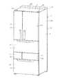
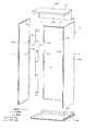
まず、第1実施形態について図1〜図8を参照して説明する。図1には冷蔵庫1の外観を示し、図2にはその冷蔵庫1の断熱キャビネット2の外観を示している。断熱キャビネット2は、この場合図3に示すように、その周壁となる左側壁部3と、右側壁部4と、奥壁部5と、天井壁部6と、底壁部7をそれぞれ別々に作成して、それらを組み合わせることにより形成したものであり、全体には、前面が開口した矩形箱状をなしている。これら左側壁部3、右側壁部4、奥壁部5、天井壁部6、底壁部7は、それぞれ断熱壁によって構成されていて、これら5個の壁部3〜7によって囲まれた空間を収納室8としている。Hereinafter, the heat insulation cabinet of the refrigerator by several embodiment is demonstrated with reference to drawings. In addition, in each embodiment, the substantially same part is attached | subjected with the same code | symbol and description is abbreviate | omitted.
(First embodiment)
First, a first embodiment will be described with reference to FIGS. FIG. 1 shows the appearance of the refrigerator 1, and FIG. 2 shows the appearance of the
断熱キャビネット2の前部には、図2に示すように、上下3段の前仕切部9a,9b,9cが設けられている。これら各前仕切部9a,9b,9cは、左側壁部3と右側壁部4の前部を連結するように設けられている。中段の前仕切部9bと下段の前仕切部9cの間には、縦仕切部10が設けられている。上段の前仕切部9aの奥側には仕切板12が設けられていて、この仕切板12の上方の空間を冷蔵室13としている。中段の前仕切部9bの奥側には、断熱性を有する仕切壁14が設けられていて、この仕切壁14と仕切板12との間の空間を野菜室15としている。冷蔵室13および野菜室15は、1〜5℃の冷蔵温度帯の貯蔵室とされる。 As shown in FIG. 2, front and rear three-
仕切壁14の下方において、縦仕切部10の左側の空間は製氷室16とされ、また、縦仕切部10の右側は小冷凍室17とされ、下段の前仕切部9cの下方の空間は主冷凍室18とされている。これら製氷室16、小冷凍室17、および主冷凍室18は、−20℃前後の冷凍温度帯の貯蔵室とされる。 Below the
図1に示すように、冷蔵室13は、断熱性を有する2枚の扉19,20によって開閉される。これら2枚の扉19,20は、それぞれヒンジ部19a、20aにより回動可能に支持された観音開き式の扉である。野菜室15、製氷室16、小冷凍室17、および主冷凍室18は、それぞれ断熱性を有する引き出し式の扉21,22,23,24によって開閉される。 As shown in FIG. 1, the
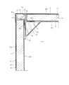
図3および図4に示すように、前記左側壁部3は、基本的に、外箱を形成する外板25Aと内箱を形成する内板26Aとの間に真空断熱パネル27を挟み込んだ構成となっている。この左側壁部3の後端部には、真空断熱パネル27の後端部を覆うように発泡断熱材28が設けられている。右側壁部4も、基本的に左側壁部3と同様に、外箱を形成する外板25Bと内箱を形成する内板26Bとの間に真空断熱パネル27を挟み込んだ構成となっている。この右側壁部4の後端部にも、真空断熱パネル27の後端部を覆うように発泡断熱材28が設けられている。奥壁部5も、基本的に左側壁部3と同様に、外箱を形成する外板25Cと内箱を形成する内板26Cとの間に真空断熱パネル27を挟み込んだ構成となっている。この奥壁部5の左右両端部には、真空断熱パネル27の左右両端部を覆うように発泡断熱材28が設けられている。 As shown in FIGS. 3 and 4, the
左側壁部3、右側壁部4および奥壁部5において、各真空断熱パネル27は、対応する外板25A,25B,25Cおよび内板26A,26B,26Cにそれぞれホットメルトからなる接着剤により接着固定されている。なお、図4および図5においては、接着剤は省略されている。 In the left
天井壁部6は、図3に示すように、外箱を形成する外板25Dと内箱を形成する内板26Dとの間に、図示はしないが真空断熱パネルと発泡断熱材を挟み込んだ構成となっている。また、底壁部7も、天井壁部6と同様に、外箱を形成する外板25Eと内箱を形成する内板26Eとの間に、図示はしないが真空断熱パネルと発泡断熱材を挟み込んだ構成となっている。天井壁部6および底壁部7の各真空断熱パネルは、例えば対応する内板26D,26Eにそれぞれホットメルトからなる接着剤により接着固定されている。 As shown in FIG. 3, the
各外板25A〜25Eは、鋼板などの金属板により構成されていて、断熱キャビネット2の外殻となる外箱25を形成する。また、各内板26A〜26Eは、合成樹脂により構成されていて、断熱キャビネット2の内箱26を形成する。この内箱26によって囲まれる内部の空間を収納室8としている。 Each of the
左側壁部3と奥壁部5の左部は、連結部材30を介して連結されている。この連結構造について説明する。連結部材30は、図3に示すように、左側壁部3と奥壁部5によって形成される左奥のコーナー部に配置され、上下方向に延びている。この連結部材30は、例えば合成樹脂製である。この連結部材30には、図5にも示すように、左右の両側の複数箇所に凹状の段部31が形成されていて、各段部31にねじ挿通孔32が形成されている。連結部材30の裏側には、三角柱状の断熱材33が配置されている。この断熱材33は、例えば発泡スチロールの成形品である。 The left
左側壁部3における内板26Aの後部および奥壁部5における内板26C左部には、前記段部31に対応して複数個の固定具34(図3、図5参照)が取り付けられている。この固定具34は、例えば合成樹脂製で、ねじ穴34aを有する角柱状のボス部34bと、このボス部34bの基端部に周囲に張り出すように設けられた張出し部34cを有している。内板26A,26Cには、固定具34を取り付ける部位に開口部35が形成されている。固定具34は、対応する内板26A,26Cの裏側からボス部34bを、開口部35を通して収納室8側に突出させるとともに、張出し部34cを内板26A,26Cの裏面に接着剤により接着固定することにより取り付けられている。 A plurality of fixtures 34 (see FIGS. 3 and 5) are attached to the rear portion of the
そして、収納室8側からねじ挿通孔32に挿通したねじ36を固定具34のねじ穴34aにねじ込むことによって、連結部材30と、左側壁部3の内板26Aおよび奥壁部5の内板26Cを連結している。したがって、左側壁部3と奥壁部5を、連結部材30を介して連結している。これにより、左側壁部3と奥壁部5は、直角となるように連結保持されている。このとき、断熱材33と内板26A,26Cが接触する部分には、シート状のシール部材37を設けている。 Then, the
なお、右側壁部4と奥壁部5の右部との間も、図示はしないが、上記左側壁部3と奥壁部5の左部と同様な構成により連結しているが、ここでは説明は省略する。
次に、真空断熱パネル27の構成について、主に図6を参照して説明する。真空断熱パネル27は、例えば細いガラス繊維をマット状にしてコア材39とし、このコア材39を、ガスバリア性を有する袋体40内に収容し、その袋体40内を真空排気して当該袋体40の開口端部を密閉した密閉部41を形成することで内部を真空減圧状態に保持したパネルであり、薄くて低い熱伝導率(断熱性)を有している。Although not shown, the
Next, the configuration of the vacuum
真空断熱パネル27の袋体40は、図6に示すように、コア材39の第1の面39aを覆う第1フィルム42と、コア材39の第1の面39aとは反対側の第2の面39bを覆う第2フィルム43とを有している。このうち、第1フィルム42は、内側の溶着層となるPE(ポリエチレン)層42aと、アルミ蒸着層(金属蒸着層)42bが設けられたEVOH(エチレン−ビニルアルコール共重合樹脂)(商品名:エバール)層42cと、ナイロン層42dと、最も外側の表面層となるPET(ポリエチレンテレフタレート)層42eの5層構造となっている。第2フィルム43は、内側の溶着層となるPE層43aと、アルミ箔層(金属箔層)43bと、ナイロン層43cと、最も外側の表面層となるPET層43dの4層構造となっている。 As shown in FIG. 6, the
このうち、溶着層となるPE層42a,43aは、耐薬品性が高く、吸水性が低く、熱溶着性に優れていて、熱溶着により密閉部41を形成するのに適している。アルミ蒸着層42bが設けられたEVOH層42cおよびアルミ箔層43bは、ともにガスバリア性に優れている。ナイロン層42d,43cは、柔軟性があり、外部から突起などが突き刺さり難い特性がある。表面層のPET層42e,43dは、強度および剛性が大きく、しかも耐薬品性が高い特性がある。 Among these, the PE layers 42a and 43a serving as the welding layers have high chemical resistance, low water absorption, and excellent thermal welding properties, and are suitable for forming the sealed
このように構成された袋体40は、コア材39の周囲において、第1フィルム42のPE層42aと第2フィルム43のPE層43aを合わせた状態でその開口端部を熱溶着して密閉部41が形成される。密閉部41は、図7に示すように、第1フィルム42側へ折り曲げられ、その端面41aを覆うようにして、規制部材である接着テープ44にて止められる。図7は、左側壁部3部分の構成を代表して示している。そして、真空断熱パネル27としては、接着テープ44にて止めた側(第1フィルム42側)を接着剤45により内板26Aの裏面に接着固定し、第2フィルム43側を接着剤45により外板25Aの裏面に接着固定する。左側壁部3の後端部において、真空断熱パネル27の後端部は前記発泡断熱材28にて覆われており、真空断熱パネル27における袋体40の密閉部41が存する側の端部が発泡断熱材28にて覆われている。なお、右側壁部4部分も、左側壁部3と同様に構成されている。 The
奥壁部5においても、真空断熱パネル27における袋体40の接着テープ44にて止めた側を接着剤により内板26Cの裏面に接着固定し、第2フィルム43側を接着剤により外板25Cの裏面に接着固定する。そして、奥壁部5において、真空断熱パネル27の左右両端部は前記発泡断熱材28にて覆われており、真空断熱パネル27における袋体40の密閉部41が存する側の端部が発泡断熱材28にて覆われている。この場合、各壁部3〜7において、真空断熱パネル27の端部を覆うように設けられた発泡断熱材28、および密閉部41の端面部41aを覆うように設けられた接着テープ44は、真空断熱パネル27における袋体40の密閉部41から当該袋体40内へ流体が浸入することを規制する規制部材を構成している。 Also in the
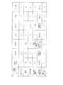
ここで、真空断熱パネル27を、各種の液体に浸して放置した場合の実験結果を図8に示している。この実験では、真空断熱パネル27を空気中に放置した場合(液体なし)と、真空断熱パネル27を各種の液体(日本酒、食用酢、醤油、赤ワイン、豆乳、メロン果汁)に浸して放置した場合において、68日間放置した後の状態を観察した。この実験では、真空断熱パネル27の密閉部41の接着テープ止めはせず、密閉部41の端面41aが露出した状態で行った。 Here, FIG. 8 shows experimental results when the vacuum
この実験結果から次のようなことがわかる。真空断熱パネル27を空気中に放置した場合(液体なし)には、68日間経過しても外観ダメージは認められなかった。しかし、真空断熱パネル27を液体に浸した場合において、特に赤ワインや食用酢に浸した場合には、袋体40の密閉部41に剥離が発生した。密閉部41に剥離が発生すると、ガスバリア性が低下し、ひいては断熱性能が低下してしまう。 From the experimental results, the following can be understood. When the
ガスバリア性の低下のメカニズムとしては、次のようなことが考えられる。酸性等の液体により、袋体40におけるEVOH層42cやナイロン層42d,43cなどの吸湿性の材料が膨潤し、各層の接着面で剥離が発生するとともに、蒸着されているアルミ蒸着層42bなどを酸化、消失させる。外部のガスは、特に剥離が発生した部分から、ガスが透過しやすいPE層42a,43aを通して、あるいは蒸着などがダメージを受けた部分から袋体40内に浸入するものと考えられる。 The following can be considered as a mechanism of the gas barrier property deterioration. The liquid such as acid swells hygroscopic materials such as the
真空断熱パネル27を使用した上記断熱キャビネット2を備えた冷蔵庫1においては、収納室8内に貯蔵された貯蔵物から液体がこぼれ、この液体が万一断熱壁内の真空断熱パネル27まで到達し、長期間経過すると、上記した実験結果に示すように、密閉部41から剥離が発生するなどして袋体40が劣化し、断熱性能が低下してしまうおそれがある。 In the refrigerator 1 equipped with the
本実施形態において、例えば収納室8内に貯蔵された貯蔵物から液体がこぼれた場合に、この液体が、左側壁部3内の真空断熱パネル27の密閉部41付近まで到達する経路としては、次の2つの経路が考えられる。第1の経路としては、図4において、連結部材30の端部と左側壁部3の内板26Aとの間の隙間、断熱材33と左側壁部3の内板26Aとの間の隙間、左側壁部3の内板26Aと奥壁部5の発泡断熱材28との間の隙間、真空断熱パネル27の袋体40と左側壁部3の発泡断熱材28および内板26Aとの間の隙間をつなぐ経路であり、この経路を第1流体浸入可能部46とする。また、第2の経路としては、図5において、連結部材30の端部と左側壁部3の内板26Aとの間の隙間、内板26Aに形成された固定具34取付け用の開口部35、固定具34の張出し部34cと内板26Aとの間の隙間、真空断熱パネル27の袋体40と内板26Aとの間の隙間をつなぐ経路であり、この経路を第2流体浸入可能部47とする。この第2流体浸入可能部47には、特に内板26Aに開口部35があるため、収納室8側の液体が真空断熱パネル27側へ一層浸入するおそれがある。 In the present embodiment, for example, when a liquid spills from a stored item stored in the
ここで、第1流体浸入可能部46には、断熱材33と左側壁部3の内板26Aとの間の隙間を塞ぐシール部材37が存し、また、左側壁部3における真空断熱パネル27の後端部には発泡断熱材28が存しているので、液体がこの第1流体浸入可能部46を通って真空断熱パネル27の密閉部41付近まで到達することを極力防止することができる。しかも、真空断熱パネル27の密閉部41の端面41aは、接着テープ44にて覆っているので、その端面41aから液体が浸入することを一層確実に防止することができる。 Here, a
また、第2流体浸入可能部47において、固定具34取付け用の開口部35の周縁部と固定具34の張出し部34cとの間、および真空断熱パネル27の袋体40と内板26Aとの間は接着剤で接着されているので、液体がこの第2流体浸入可能部47を通って真空断熱パネル27の密閉部41付近まで到達することも極力防止することができる。しかもこの場合も、真空断熱パネル27の密閉部41の端面41aは、接着テープ44にて覆っているので、その端面41aから液体が浸入することを一層確実に防止することができる。 Further, in the second fluid ingressible portion 47, between the peripheral portion of the
なお、収納室8内に貯蔵された貯蔵物からこぼれた液体が、右側壁部4内の真空断熱パネル27の密閉部41付近まで到達する経路も、上記した左側壁部3の経路と同様な事情となるので、説明は省略する。 In addition, the path | route in which the liquid spilled from the stored thing stored in the
また、収納室8内に貯蔵された貯蔵物から液体がこぼれた場合に、この液体が、奥壁部5内の真空断熱パネル27の密閉部41付近まで到達する経路としても、次の2つの経路が考えられる。第1の経路としては、図4において、連結部材30の端部と奥壁部5の内板26Cとの間の隙間、断熱材33と奥壁部5の内板26Cとの間の隙間、内板26Cと発泡断熱材28との間の隙間、真空断熱パネル27の袋体40と内板26Cとの間の隙間をつなぐ経路であり、この経路を第3流体浸入可能部48とする。また、第2の経路としては、図5において、連結部材30の端部と奥壁部5の内板26Cとの間の隙間、内板26Cに形成された固定具34取付け用の開口部35、固定具34の張出し部34cと内板26Cとの間の隙間、真空断熱パネル27の袋体40と内板26Cとの間の隙間をつなぐ経路であり、この経路を第4流体浸入可能部49とする。この第4流体浸入可能部49には、特に内板26Cに開口部35があるため、収納室8側の液体が真空断熱パネル27側へ一層浸入するおそれがある。 In addition, when a liquid spills from the stored material stored in the
ここで、第3流体浸入可能部48には、断熱材33と奥壁部5の内板26Cとの間の隙間を塞ぐシール部材37が存し、また、奥壁部5における真空断熱パネル27の左右両端部には発泡断熱材28が存しているので、液体がこの第3流体浸入可能部48を通って真空断熱パネル27の密閉部41付近まで到達することを極力防止することができる。しかも、真空断熱パネル27の密閉部41の端面41aは、接着テープ44にて覆っているので、その端面41aから液体が浸入することを一層確実に防止することができる。 Here, a
また、第4流体浸入可能部49において、固定具34取付け用の開口部35の周縁部と固定具34の張出し部34cとの間、および真空断熱パネル27の袋体40と内板26Cとの間は接着剤で接着されているので、液体がこの第4流体浸入可能部49を通って真空断熱パネル27の密閉部41付近まで到達することも極力防止することができる。しかもこの場合も、真空断熱パネル27の密閉部41の端面41aは、接着テープ44にて覆っているので、その端面41aから液体が浸入することを一層確実に防止することができる。 Further, in the fourth
なお、天井壁部6および底壁部7にも、図示はしないが、上記と同様な構成の真空断熱パネル27を設けていて、その袋体40の密閉部41は、その端面41aを覆うように接着テープ44で止めており、また、真空断熱パネル27の周囲の端部を発泡断熱材28で覆っている。このため、収納室8内でこぼれた液体が、それら天井壁部6および底壁部7の真空断熱パネル27の密閉部41付近まで浸入することを極力防止できるとともに、密閉部41の端面41aから液体が浸入することも一層確実に防止することができる。 Although not shown, the
また、上記した実施形態によれば、次のような作用効果も得られる。各壁部(左側壁部3、右側壁部4、奥壁部5、天井壁部6、底壁部7)の真空断熱パネル27における袋体40は、それぞれ複数の層が積層された第1フィルム42および第2フィルム43によって形成されていて、それらの最も外側の表面層は、PET層42e,43dとしている。PET層42e,43dは、強度および剛性が大きく、しかも耐薬品性が高い特性があるため、劣化し難く、耐久性の向上を図ることができる。 Moreover, according to the above-described embodiment, the following operational effects can also be obtained. The
なお、第1フィルム42および第2フィルム43の表面層をナイロン層とすることも考えられるが、ナイロン層は、吸湿しやすく、耐薬品性に弱いため、劣化し易くなる欠点がある。本実施形態によれば、そのような不具合を防止できる。 Although the surface layer of the
また、真空断熱パネル27の袋体40を構成する第1フィルム42および第2フィルム43は、当該袋体40の開口端部を密閉する際に溶着される溶着層が共にPE層42a,43aとしている。PE層42a,43aは、耐薬品性が高く、吸水性が低く、熱溶着性に優れていて、熱溶着により密閉部41を形成するのに適している。溶着層には、PEに代えて、例えばポリプロピレン(PP)を用いることもできる。 Moreover, as for the
(第2実施形態)
図9は第2実施形態を示す。この第2実施形態においては、第1実施形態とは次の点が異なっている。左側壁部3において、真空断熱パネル27の袋体40の密閉部41を、外板25A側へ折り返し、接着テープ44により端面41aを覆うように固定している。また、奥壁部5において、真空断熱パネル27の袋体40の密閉部41を、外板25C側へ折り返し、接着テープ44により端面41aを覆うように固定している。図示はしないが、右側壁部4、天井壁部6、底壁部7においても、真空断熱パネル27の袋体40の密閉部41を、外板25B,25D,25E側へ折り返し、接着テープ44により端面41aを覆うように固定している。(Second Embodiment)
FIG. 9 shows a second embodiment. The second embodiment is different from the first embodiment in the following points. In the left
このような構成とした場合には、各断熱壁において、真空断熱パネル27における密閉部41の端面41aを、収納室8から遠ざけることができるから、真空断熱パネル27の密閉部41が劣化することを一層防止することができる。 In such a configuration, in each heat insulating wall, the
(第3実施形態)
図10は第3実施形態を示す。この第3実施形態においては、第1実施形態とは次の点が異なっている。真空断熱パネル51の袋体52において、第1フィルム53は、第2フィルム43と同様な構成としている。すなわち、第1フィルム53は、内側の溶着層となるPE層53aと、アルミ箔層(金属箔層)53bと、ナイロン層53cと、最も外側の表面層となるPET層53dの4層構造となっており、アルミ蒸着層を有するEVOH層をアルミ箔層53bに代えた構成となっている。(Third embodiment)
FIG. 10 shows a third embodiment. The third embodiment is different from the first embodiment in the following points. In the
このような構成とした場合、第1フィルム53および第2フィルム43ともに、ガスバリア性に優れるアルミ箔層53b,43bを有している。アルミ箔層53b,43bは、厚さが10μmレベルであり、酸などの液体が浸入しても酸化、消失し難く、バリア性に優れているため、劣化を抑え、耐久性の向上を図ることができる。なお、アルミ蒸着層の場合、厚さが0.1μm以下であり、酸などの液体が浸入した場合に、アルミ箔に比べて、酸化し、消失しやすいという不具合があるが、本実施形態によれば、これを解消できる。 When it is set as such a structure, both the
(第4実施形態)
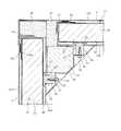
図11は第4実施形態を示す。この第4実施形態においては、第1実施形態とは次の点が異なっている。奥壁部5における内板26Cの左右両端部(図11には左端部のみ示す)に、収納室8側である前方へ突出する突出部55を一体に形成している。突出部55は、上から見て直角三角形状をなしている。内板26Cの端部56は、後方に向けられ、シール部材57を介して外板25Cの内面に当接させている。突出部55の内部には、例えば発泡スチロールの成形品である三角柱状の断熱材58が収容されている。(Fourth embodiment)
FIG. 11 shows a fourth embodiment. The fourth embodiment is different from the first embodiment in the following points. Protruding
左側壁部3における内板26Aの後部には、収納室8側である右側へ突出する位置決め凸部59が設けられていて、この位置決め凸部59の後面を、前記突出部55の前端部に当接させている。内板26Aの後端部60は左側に向けられ、シール部材57を介して外板25Cの内面に当接させている。図示はしないが、奥壁部5と右側壁部4との間にも上記と同様な構成が設けられている。 A positioning
上記した実施形態において、例えば収納室8内に貯蔵された貯蔵物から液体がこぼれた場合に、この液体が、左側壁部3内の真空断熱パネル27の密閉部41付近まで到達する経路としては、次の経路が考えられる。その経路としては、左側壁部3の内板26A(位置決め凸部59を含む)と奥壁部5の内板26Cの突出部55との間の隙間、左側壁部3の内板26Aの外面、その内板26Aの後端部60と外板25Aとの間の隙間、内板26Aと真空断熱パネル27の袋体40との間の隙間とをつなぐ経路であり、この経路を第1流体浸入可能部61とする。 In the above-described embodiment, for example, when a liquid spills from a stored item stored in the
この第1流体浸入可能部61には、内板26Aの後端部60と外板25Aとの間の隙間を塞ぐシール部材57が存しているので、液体がこの第1流体浸入可能部61を通って真空断熱パネル27の密閉部41付近まで到達することを極力防止することができる。しかも、真空断熱パネル27の密閉部41の端面41aは、接着テープ44にて覆っているので、その端面41aから液体が浸入することを一層確実に防止することができる。なお、右側壁部4側も、上記左側壁部3側と同様である。 Since the first
また、収納室8内に貯蔵された貯蔵物から液体がこぼれた場合に、この液体が、奥壁部5内の真空断熱パネル27の密閉部41付近まで到達する経路としても、次の経路が考えられる。その経路としては、左側壁部3の内板26Aと奥壁部5の内板26Cの突出部55との間の隙間、奥壁部5の内板26Cの外面、その内板26Cの端部56と外板25Cとの間の隙間、内板26Cと真空断熱パネル27の袋体40との間の隙間とをつなぐ経路であり、この経路を第2流体浸入可能部62とする。 Further, when a liquid is spilled from the stored item stored in the
この第2流体浸入可能部62にも、内板26Cの端部56と外板25Cとの間の隙間を塞ぐシール部材57が存しているので、液体がこの第2流体浸入可能部62を通って真空断熱パネル27の密閉部41付近まで到達することを極力防止することができる。しかも、真空断熱パネル27の密閉部41の端面41aは、接着テープ44にて覆っているので、その端面41aから液体が浸入することを一層確実に防止することができる。 Since the
なお、本実施形態において、左側壁部3において、真空断熱パネル27の後端部を覆うように発泡断熱材を設けるとともに、右側壁部4においても、同様に真空断熱パネル27の後端部を覆うように発泡断熱材を設けるようにしてもよい。また、奥壁部5において、真空断熱パネル27の左右両端部を覆うように発泡断熱材を設けるようにしてもよい。このようにした場合には、収納室8側でこぼれた液体が真空断熱パネル27の密閉部41付近まで到達することを一層防止することができる。 In the present embodiment, the
(その他の実施形態)
外箱25を形成する外板25A〜25Eは、すべてばらばらである必要はなく、一部が接続されていてもよい。また、内箱26を形成する内板26A〜26Eも、すべてがばらばらである必要はなく、一部が接続されていてもよい。(Other embodiments)
The
断熱キャビネットとしては、冷蔵庫にかぎられず、温蔵庫、冷凍ショーケースその他の恒温キャビネットとして使用することができる。
本発明のいくつかの実施形態を説明したが、これらの実施形態は、例として提示したものであり、発明の範囲を限定することは意図していない。これら新規な実施形態は、その他の様々な形態で実施されることが可能であり、発明の要旨を逸脱しない範囲で、種々の省略、置き換え、変更を行うことができる。これら実施形態やその変形は、発明の範囲や要旨に含まれるとともに、特許請求の範囲に記載された発明とその均等の範囲に含まれる。The heat insulation cabinet is not limited to a refrigerator, and can be used as a thermostat cabinet, a freezer showcase or other constant temperature cabinet.
Although several embodiments of the present invention have been described, these embodiments are presented by way of example and are not intended to limit the scope of the invention. These novel embodiments can be implemented in various other forms, and various omissions, replacements, and changes can be made without departing from the scope of the invention. These embodiments and modifications thereof are included in the scope and gist of the invention, and are included in the invention described in the claims and the equivalents thereof.
以上説明したように、本実施形態の断熱キャビネットによれば、断熱壁の内部に配置される真空断熱パネルにおける袋体の密閉部から当該袋体内へ流体が浸入することを規制する規制部材を設けたことにより、真空断熱パネルの劣化を極力防止できて耐久性の向上を図ることができる。 As described above, according to the heat insulation cabinet of the present embodiment, there is provided a restriction member that restricts fluid from entering the bag body from the sealed portion of the bag body in the vacuum heat insulation panel disposed inside the heat insulation wall. As a result, it is possible to prevent deterioration of the vacuum heat insulation panel as much as possible and to improve durability.
図面中、1は冷蔵庫、2は断熱キャビネット、3は左側壁部(断熱壁)、4は右側壁部(断熱壁)、5は奥壁部(断熱壁)、6は天井壁部(断熱壁)、7は底壁部(断熱壁)、8は収納室、25は外箱、25A〜25Eは外板、26は内箱、26A〜26Eは内板、27は真空断熱パネル、28は発泡断熱材(規制部材)、35は開口部、37はシール部材、39はコア材、40は袋体、41は密閉部、42は第1フィルム、42aはPE層、42bはアルミ蒸着層、42cはEVOH層、42dはナイロン層、42eはPET層、43は第2フィルム、43aはPE層、43bはアルミ箔層(金属箔層)、43cはナイロン層、43dはPET層、44は接着テープ(規制部材)、46は第1流体浸入可能部、47は第2流体浸入可能部、48は第3流体浸入可能部、49は第4流体浸入可能部、51は真空断熱パネル、52は袋体、53は第1フィルム、53aはPE層、53bはアルミ箔層(金属箔層)、53cはナイロン層、53dはPET層、61は第1流体浸入可能部、62は第2流体浸入可能部を示す。 In the drawings, 1 is a refrigerator, 2 is a heat insulation cabinet, 3 is a left side wall (insulation wall), 4 is a right side wall (insulation wall), 5 is a back wall (insulation wall), and 6 is a ceiling wall (insulation wall). ), 7 is a bottom wall (heat insulating wall), 8 is a storage chamber, 25 is an outer box, 25A to 25E are outer plates, 26 is an inner box, 26A to 26E are inner plates, 27 is a vacuum heat insulating panel, and 28 is foamed Insulating material (regulating member), 35 is an opening, 37 is a sealing member, 39 is a core material, 40 is a bag, 41 is a sealing part, 42 is a first film, 42a is a PE layer, 42b is an aluminum vapor deposition layer, 42c Is an EVOH layer, 42d is a nylon layer, 42e is a PET layer, 43 is a second film, 43a is a PE layer, 43b is an aluminum foil layer (metal foil layer), 43c is a nylon layer, 43d is a PET layer, 44 is an adhesive tape (Regulating member), 46 is a first fluid intrusionable portion, 47 is a second fluid intrusion possible portion, 8 is a third fluid ingressible portion, 49 is a fourth fluid intrusion possible portion, 51 is a vacuum heat insulating panel, 52 is a bag body, 53 is a first film, 53a is a PE layer, 53b is an aluminum foil layer (metal foil layer) 53c is a nylon layer, 53d is a PET layer, 61 is a first fluid intrusionable portion, and 62 is a second fluid intrusion possible portion.
Claims (8)
Translated fromJapanese前記収納室内と前記真空断熱パネルとの間に、前記内板に形成された開口部を有する流体浸入可能部が存していて、
前記真空断熱パネルは、減圧状態の袋体内にコア材が収容され、前記袋体の開口端部が密閉された構成であり、
前記真空断熱パネルにおける前記袋体の密閉部分から当該袋体内へ酒や酢などの流体が浸入することを規制する規制部材を設けたことを特徴とする断熱キャビネット。A heat insulating cabinet having a heat insulating wall configured by disposing a vacuum heat insulating panel between an outer plate forming an outer box and an inner plate forming an inner box, and having an interior surrounded by the inner box as a storage chamber; There,
Between the storage chamber and the vacuum heat insulation panel, there is a fluid intrusionable portion having an opening formed in the inner plate,
The vacuum insulation panel hasa configuration in which acore material is accommodated in a bag body in areduced pressure state, and an opening end of the bag body is sealed ,
A heat insulation cabinet provided with a restricting member for restricting a fluid such as liquor or vinegar from entering a sealed body of the bag body in the vacuum heat insulation panel.
Priority Applications (5)
| Application Number | Priority Date | Filing Date | Title |
|---|---|---|---|
| JP2011266795AJP5860685B2 (en) | 2011-12-06 | 2011-12-06 | Insulation cabinet |
| CN201280060161.9ACN103975210B (en) | 2011-12-06 | 2012-11-07 | Insulated cabinet |
| EP12855454.0AEP2789951B1 (en) | 2011-12-06 | 2012-11-07 | Insulated cabinet |
| PCT/JP2012/078842WO2013084647A1 (en) | 2011-12-06 | 2012-11-07 | Insulated cabinet |
| TW101142662ATWI558966B (en) | 2011-12-06 | 2012-11-15 | Insulated cabinet |
Applications Claiming Priority (1)
| Application Number | Priority Date | Filing Date | Title |
|---|---|---|---|
| JP2011266795AJP5860685B2 (en) | 2011-12-06 | 2011-12-06 | Insulation cabinet |
Publications (2)
| Publication Number | Publication Date |
|---|---|
| JP2013119967A JP2013119967A (en) | 2013-06-17 |
| JP5860685B2true JP5860685B2 (en) | 2016-02-16 |
Family
ID=48574026
Family Applications (1)
| Application Number | Title | Priority Date | Filing Date |
|---|---|---|---|
| JP2011266795AActiveJP5860685B2 (en) | 2011-12-06 | 2011-12-06 | Insulation cabinet |
Country Status (5)
| Country | Link |
|---|---|
| EP (1) | EP2789951B1 (en) |
| JP (1) | JP5860685B2 (en) |
| CN (1) | CN103975210B (en) |
| TW (1) | TWI558966B (en) |
| WO (1) | WO2013084647A1 (en) |
Families Citing this family (49)
| Publication number | Priority date | Publication date | Assignee | Title |
|---|---|---|---|---|
| US9221210B2 (en) | 2012-04-11 | 2015-12-29 | Whirlpool Corporation | Method to create vacuum insulated cabinets for refrigerators |
| US9071907B2 (en) | 2012-04-02 | 2015-06-30 | Whirpool Corporation | Vacuum insulated structure tubular cabinet construction |
| JP6089803B2 (en)* | 2013-03-07 | 2017-03-08 | 三菱電機株式会社 | Hot water storage water heater |
| US10052819B2 (en) | 2014-02-24 | 2018-08-21 | Whirlpool Corporation | Vacuum packaged 3D vacuum insulated door structure and method therefor using a tooling fixture |
| US9599392B2 (en) | 2014-02-24 | 2017-03-21 | Whirlpool Corporation | Folding approach to create a 3D vacuum insulated door from 2D flat vacuum insulation panels |
| US9689604B2 (en) | 2014-02-24 | 2017-06-27 | Whirlpool Corporation | Multi-section core vacuum insulation panels with hybrid barrier film envelope |
| US9476633B2 (en) | 2015-03-02 | 2016-10-25 | Whirlpool Corporation | 3D vacuum panel and a folding approach to create the 3D vacuum panel from a 2D vacuum panel of non-uniform thickness |
| US10161669B2 (en) | 2015-03-05 | 2018-12-25 | Whirlpool Corporation | Attachment arrangement for vacuum insulated door |
| US9897370B2 (en) | 2015-03-11 | 2018-02-20 | Whirlpool Corporation | Self-contained pantry box system for insertion into an appliance |
| US9441779B1 (en) | 2015-07-01 | 2016-09-13 | Whirlpool Corporation | Split hybrid insulation structure for an appliance |
| KR102456642B1 (en) | 2015-08-03 | 2022-10-19 | 엘지전자 주식회사 | Vacuum adiabatic body and refrigerator |
| KR102498210B1 (en) | 2015-08-03 | 2023-02-09 | 엘지전자 주식회사 | Vacuum adiabatic body and refrigerator |
| KR102442973B1 (en) | 2015-08-03 | 2022-09-14 | 엘지전자 주식회사 | Vacuum insulator and refrigerator |
| KR102447245B1 (en) | 2015-08-03 | 2022-09-27 | 엘지전자 주식회사 | Vacuum insulator and refrigerator |
| KR102529852B1 (en) | 2015-08-03 | 2023-05-08 | 엘지전자 주식회사 | Vacuum adiabatic body and refrigerator |
| KR102529853B1 (en) | 2015-08-03 | 2023-05-08 | 엘지전자 주식회사 | Vacuum adiabatic body, fabricating method for the Vacuum adiabatic body, porous substance package, and refrigerator |
| CN107923701B (en) | 2015-08-03 | 2020-04-24 | Lg电子株式会社 | Vacuum insulator and refrigerator |
| KR102525551B1 (en) | 2015-08-03 | 2023-04-25 | 엘지전자 주식회사 | Vacuum adiabatic body and refrigerator |
| KR102497139B1 (en) | 2015-08-03 | 2023-02-07 | 엘지전자 주식회사 | Vacuum adiabatic body |
| KR20170016188A (en) | 2015-08-03 | 2017-02-13 | 엘지전자 주식회사 | Vacuum adiabatic body and refrigerator |
| KR102525550B1 (en) | 2015-08-03 | 2023-04-25 | 엘지전자 주식회사 | Vacuum adiabatic body and refrigerator |
| KR102502160B1 (en) | 2015-08-03 | 2023-02-21 | 엘지전자 주식회사 | Vacuum adiabatic body and refrigerator |
| KR102466469B1 (en) | 2015-08-03 | 2022-11-11 | 엘지전자 주식회사 | Vacuum adiabatic body and refrigerator |
| KR102466470B1 (en)* | 2015-08-04 | 2022-11-11 | 엘지전자 주식회사 | Vacuum adiabatic body and refrigerator |
| US10422573B2 (en) | 2015-12-08 | 2019-09-24 | Whirlpool Corporation | Insulation structure for an appliance having a uniformly mixed multi-component insulation material, and a method for even distribution of material combinations therein |
| US10429125B2 (en) | 2015-12-08 | 2019-10-01 | Whirlpool Corporation | Insulation structure for an appliance having a uniformly mixed multi-component insulation material, and a method for even distribution of material combinations therein |
| US10041724B2 (en) | 2015-12-08 | 2018-08-07 | Whirlpool Corporation | Methods for dispensing and compacting insulation materials into a vacuum sealed structure |
| US11052579B2 (en) | 2015-12-08 | 2021-07-06 | Whirlpool Corporation | Method for preparing a densified insulation material for use in appliance insulated structure |
| US10222116B2 (en) | 2015-12-08 | 2019-03-05 | Whirlpool Corporation | Method and apparatus for forming a vacuum insulated structure for an appliance having a pressing mechanism incorporated within an insulation delivery system |
| US9791205B2 (en) | 2015-12-09 | 2017-10-17 | Whirlpool Corporation | Insulating material with renewable resource component |
| US10422569B2 (en) | 2015-12-21 | 2019-09-24 | Whirlpool Corporation | Vacuum insulated door construction |
| US9840042B2 (en) | 2015-12-22 | 2017-12-12 | Whirlpool Corporation | Adhesively secured vacuum insulated panels for refrigerators |
| US9752818B2 (en) | 2015-12-22 | 2017-09-05 | Whirlpool Corporation | Umbilical for pass through in vacuum insulated refrigerator structures |
| US10018406B2 (en) | 2015-12-28 | 2018-07-10 | Whirlpool Corporation | Multi-layer gas barrier materials for vacuum insulated structure |
| US10610985B2 (en) | 2015-12-28 | 2020-04-07 | Whirlpool Corporation | Multilayer barrier materials with PVD or plasma coating for vacuum insulated structure |
| US10807298B2 (en) | 2015-12-29 | 2020-10-20 | Whirlpool Corporation | Molded gas barrier parts for vacuum insulated structure |
| US10030905B2 (en) | 2015-12-29 | 2018-07-24 | Whirlpool Corporation | Method of fabricating a vacuum insulated appliance structure |
| US11247369B2 (en) | 2015-12-30 | 2022-02-15 | Whirlpool Corporation | Method of fabricating 3D vacuum insulated refrigerator structure having core material |
| WO2017180145A1 (en) | 2016-04-15 | 2017-10-19 | Whirlpool Corporation | Vacuum insulated refrigerator structure with three dimensional characteristics |
| WO2017180147A1 (en) | 2016-04-15 | 2017-10-19 | Whirlpool Corporation | Vacuum insulated refrigerator cabinet |
| US11320193B2 (en) | 2016-07-26 | 2022-05-03 | Whirlpool Corporation | Vacuum insulated structure trim breaker |
| WO2018034665A1 (en) | 2016-08-18 | 2018-02-22 | Whirlpool Corporation | Machine compartment for a vacuum insulated structure |
| WO2018101954A1 (en) | 2016-12-02 | 2018-06-07 | Whirlpool Corporation | Hinge support assembly |
| US10907888B2 (en) | 2018-06-25 | 2021-02-02 | Whirlpool Corporation | Hybrid pigmented hot stitched color liner system |
| KR102617454B1 (en)* | 2018-06-27 | 2023-12-26 | 엘지전자 주식회사 | Vacuum adiabatic body, and refrigerator |
| EP3708935B1 (en)* | 2019-03-13 | 2024-12-11 | Electrolux Appliances Aktiebolag | Method for fixing a built-in domestic appliance to a furniture |
| US11692763B2 (en)* | 2020-10-30 | 2023-07-04 | Whirlpool Corporation | Insulation materials for a vacuum insulated structure and methods of forming |
| USD990562S1 (en) | 2022-04-15 | 2023-06-27 | James M. Kunert | Combination electrical cabinet and sign |
| US11619055B1 (en) | 2022-06-22 | 2023-04-04 | James M. Kunert | Outdoor electrical cabinet and method of construction |
Family Cites Families (13)
| Publication number | Priority date | Publication date | Assignee | Title |
|---|---|---|---|---|
| JP2728318B2 (en) | 1991-02-15 | 1998-03-18 | シャープ株式会社 | Manufacturing method of vacuum insulation box |
| JPH06147744A (en) | 1992-11-09 | 1994-05-27 | Hitachi Ltd | Cold storage refrigerator |
| WO1995019255A1 (en)* | 1994-01-12 | 1995-07-20 | Oceaneering International, Inc. | Enclosure for thermoelectric refrigerator and method |
| US5950395A (en)* | 1995-06-20 | 1999-09-14 | Sanyo Electric Co., Ltd. | Heat insulating structure and production process thereof |
| US5900299A (en)* | 1996-12-23 | 1999-05-04 | Wynne; Nicholas | Vacuum insulated panel and container and method of production |
| JP2005299972A (en)* | 2004-04-08 | 2005-10-27 | Sanyo Electric Co Ltd | Refrigerator |
| JP2006029448A (en)* | 2004-07-15 | 2006-02-02 | Toshiba Corp | Vacuum insulation panel and refrigerator using the vacuum insulation panel |
| AU2006305083B2 (en)* | 2005-10-18 | 2011-01-06 | Lg Electronics Inc. | Vacuum insulation panel and insulation structure of refrigerator applying the same |
| JP2007253974A (en)* | 2006-03-22 | 2007-10-04 | Kurabo Ind Ltd | Insulator, opposing structure and heat insulation container |
| JP4695663B2 (en)* | 2008-03-19 | 2011-06-08 | 日立アプライアンス株式会社 | refrigerator |
| JP2010169302A (en)* | 2009-01-22 | 2010-08-05 | Panasonic Corp | refrigerator |
| JP2011106664A (en)* | 2009-10-23 | 2011-06-02 | Panasonic Corp | Vacuum heat insulating material, heat insulating box, and heat insulating body |
| JP2011237087A (en)* | 2010-05-10 | 2011-11-24 | Hitachi Appliances Inc | Refrigerator |
- 2011
- 2011-12-06JPJP2011266795Apatent/JP5860685B2/enactiveActive
- 2012
- 2012-11-07WOPCT/JP2012/078842patent/WO2013084647A1/ennot_activeCeased
- 2012-11-07CNCN201280060161.9Apatent/CN103975210B/enactiveActive
- 2012-11-07EPEP12855454.0Apatent/EP2789951B1/enactiveActive
- 2012-11-15TWTW101142662Apatent/TWI558966B/ennot_activeIP Right Cessation
Also Published As
| Publication number | Publication date |
|---|---|
| TWI558966B (en) | 2016-11-21 |
| EP2789951A1 (en) | 2014-10-15 |
| JP2013119967A (en) | 2013-06-17 |
| CN103975210A (en) | 2014-08-06 |
| WO2013084647A1 (en) | 2013-06-13 |
| CN103975210B (en) | 2017-03-22 |
| EP2789951B1 (en) | 2020-10-14 |
| EP2789951A4 (en) | 2015-08-12 |
| TW201329408A (en) | 2013-07-16 |
Similar Documents
| Publication | Publication Date | Title |
|---|---|---|
| JP5860685B2 (en) | Insulation cabinet | |
| JP5337681B2 (en) | refrigerator | |
| JP2014052111A (en) | Refrigerator | |
| KR20170044081A (en) | Vacuum heat insulating material, the method of manufacturing the same and refrigerator including the same | |
| JP2017511445A5 (en) | ||
| JP2017141053A (en) | Foldable cold insulation box | |
| JP5401258B2 (en) | refrigerator | |
| JP2016080281A (en) | Heat insulation box body and heat insulation door | |
| JP2011099566A (en) | Vacuum heat insulating panel and refrigerator | |
| CN111503962B (en) | Refrigerator and vacuum heat insulation plate | |
| JP6382596B2 (en) | refrigerator | |
| JP2017154776A (en) | Cold insulation/hot insulation box | |
| JP6875221B2 (en) | refrigerator | |
| JP2012229849A (en) | Refrigerator and freezer | |
| JP2021103080A (en) | refrigerator | |
| JP6605090B2 (en) | Vacuum insulation panel | |
| JP2015001290A (en) | Vacuum heat insulation material and refrigerator | |
| JP2016200309A (en) | refrigerator | |
| JP5098149B2 (en) | vending machine | |
| JP6469941B2 (en) | refrigerator | |
| JP5715937B2 (en) | Insulation cabinet | |
| JP7521879B2 (en) | Refrigerators and vacuum insulation panels | |
| JP2017032152A (en) | refrigerator | |
| JP5897317B2 (en) | refrigerator | |
| KR20180125759A (en) | Refrigerator |
Legal Events
| Date | Code | Title | Description |
|---|---|---|---|
| A711 | Notification of change in applicant | Free format text:JAPANESE INTERMEDIATE CODE: A712 Effective date:20140206 | |
| A521 | Request for written amendment filed | Free format text:JAPANESE INTERMEDIATE CODE: A523 Effective date:20140221 | |
| A621 | Written request for application examination | Free format text:JAPANESE INTERMEDIATE CODE: A621 Effective date:20141010 | |
| A131 | Notification of reasons for refusal | Free format text:JAPANESE INTERMEDIATE CODE: A131 Effective date:20150526 | |
| A521 | Request for written amendment filed | Free format text:JAPANESE INTERMEDIATE CODE: A523 Effective date:20150716 | |
| A131 | Notification of reasons for refusal | Free format text:JAPANESE INTERMEDIATE CODE: A131 Effective date:20150825 | |
| A521 | Request for written amendment filed | Free format text:JAPANESE INTERMEDIATE CODE: A523 Effective date:20151020 | |
| TRDD | Decision of grant or rejection written | ||
| A01 | Written decision to grant a patent or to grant a registration (utility model) | Free format text:JAPANESE INTERMEDIATE CODE: A01 Effective date:20151124 | |
| A61 | First payment of annual fees (during grant procedure) | Free format text:JAPANESE INTERMEDIATE CODE: A61 Effective date:20151221 | |
| R150 | Certificate of patent or registration of utility model | Ref document number:5860685 Country of ref document:JP Free format text:JAPANESE INTERMEDIATE CODE: R150 | |
| S111 | Request for change of ownership or part of ownership | Free format text:JAPANESE INTERMEDIATE CODE: R313117 | |
| R371 | Transfer withdrawn | Free format text:JAPANESE INTERMEDIATE CODE: R371 | |
| S111 | Request for change of ownership or part of ownership | Free format text:JAPANESE INTERMEDIATE CODE: R313117 | |
| S531 | Written request for registration of change of domicile | Free format text:JAPANESE INTERMEDIATE CODE: R313531 | |
| R350 | Written notification of registration of transfer | Free format text:JAPANESE INTERMEDIATE CODE: R350 |