JP5859650B2 - Surgical instrument with disengageable handle - Google Patents
Surgical instrument with disengageable handleDownload PDFInfo
- Publication number
- JP5859650B2 JP5859650B2JP2014526508AJP2014526508AJP5859650B2JP 5859650 B2JP5859650 B2JP 5859650B2JP 2014526508 AJP2014526508 AJP 2014526508AJP 2014526508 AJP2014526508 AJP 2014526508AJP 5859650 B2JP5859650 B2JP 5859650B2
- Authority
- JP
- Japan
- Prior art keywords
- surgical instrument
- axis
- distal
- handle
- longitudinal axis
- Prior art date
- Legal status (The legal status is an assumption and is not a legal conclusion. Google has not performed a legal analysis and makes no representation as to the accuracy of the status listed.)
- Expired - Fee Related
Links
- 230000005540biological transmissionEffects0.000claimsdescription72
- 230000033001locomotionEffects0.000claimsdescription40
- 230000008878couplingEffects0.000claimsdescription37
- 238000010168coupling processMethods0.000claimsdescription37
- 238000005859coupling reactionMethods0.000claimsdescription37
- 238000013519translationMethods0.000claimsdescription24
- 230000007246mechanismEffects0.000claimsdescription20
- 230000008054signal transmissionEffects0.000claimsdescription7
- 230000008859changeEffects0.000claimsdescription4
- 238000001356surgical procedureMethods0.000claimsdescription3
- 230000011664signalingEffects0.000claims2
- 238000005452bendingMethods0.000description14
- 230000008901benefitEffects0.000description7
- 238000003780insertionMethods0.000description5
- 230000037431insertionEffects0.000description5
- 230000036544postureEffects0.000description5
- 210000003811fingerAnatomy0.000description4
- 238000002357laparoscopic surgeryMethods0.000description4
- 238000000034methodMethods0.000description4
- 239000011295pitchSubstances0.000description4
- 238000004519manufacturing processMethods0.000description3
- 230000009471actionEffects0.000description2
- 238000004891communicationMethods0.000description2
- 238000002674endoscopic surgeryMethods0.000description2
- 239000000463materialSubstances0.000description2
- 238000002324minimally invasive surgeryMethods0.000description2
- 230000035515penetrationEffects0.000description2
- 238000007789sealingMethods0.000description2
- 230000001954sterilising effectEffects0.000description2
- 238000004659sterilization and disinfectionMethods0.000description2
- 210000000707wristAnatomy0.000description2
- 210000001015abdomenAnatomy0.000description1
- 238000013459approachMethods0.000description1
- 238000010276constructionMethods0.000description1
- 230000001186cumulative effectEffects0.000description1
- 238000011161developmentMethods0.000description1
- 230000009365direct transmissionEffects0.000description1
- 238000000605extractionMethods0.000description1
- 238000009434installationMethods0.000description1
- 230000000149penetrating effectEffects0.000description1
- 229920001296polysiloxanePolymers0.000description1
- 230000001681protective effectEffects0.000description1
- 229920005989resinPolymers0.000description1
- 239000011347resinSubstances0.000description1
- 230000000153supplemental effectEffects0.000description1
- 210000003813thumbAnatomy0.000description1
- 230000007704transitionEffects0.000description1
- 238000011282treatmentMethods0.000description1
Images


Classifications
- A—HUMAN NECESSITIES
- A61—MEDICAL OR VETERINARY SCIENCE; HYGIENE
- A61B—DIAGNOSIS; SURGERY; IDENTIFICATION
- A61B17/00—Surgical instruments, devices or methods
- A61B17/28—Surgical forceps
- A61B17/29—Forceps for use in minimally invasive surgery
- A61B17/2909—Handles
- A—HUMAN NECESSITIES
- A61—MEDICAL OR VETERINARY SCIENCE; HYGIENE
- A61B—DIAGNOSIS; SURGERY; IDENTIFICATION
- A61B17/00—Surgical instruments, devices or methods
- A—HUMAN NECESSITIES
- A61—MEDICAL OR VETERINARY SCIENCE; HYGIENE
- A61B—DIAGNOSIS; SURGERY; IDENTIFICATION
- A61B17/00—Surgical instruments, devices or methods
- A61B17/00234—Surgical instruments, devices or methods for minimally invasive surgery
- A—HUMAN NECESSITIES
- A61—MEDICAL OR VETERINARY SCIENCE; HYGIENE
- A61B—DIAGNOSIS; SURGERY; IDENTIFICATION
- A61B17/00—Surgical instruments, devices or methods
- A61B2017/00017—Electrical control of surgical instruments
- A—HUMAN NECESSITIES
- A61—MEDICAL OR VETERINARY SCIENCE; HYGIENE
- A61B—DIAGNOSIS; SURGERY; IDENTIFICATION
- A61B17/00—Surgical instruments, devices or methods
- A61B17/00234—Surgical instruments, devices or methods for minimally invasive surgery
- A61B2017/00292—Surgical instruments, devices or methods for minimally invasive surgery mounted on or guided by flexible, e.g. catheter-like, means
- A61B2017/003—Steerable
- A61B2017/00318—Steering mechanisms
- A61B2017/00323—Cables or rods
- A—HUMAN NECESSITIES
- A61—MEDICAL OR VETERINARY SCIENCE; HYGIENE
- A61B—DIAGNOSIS; SURGERY; IDENTIFICATION
- A61B17/00—Surgical instruments, devices or methods
- A61B2017/00367—Details of actuation of instruments, e.g. relations between pushing buttons, or the like, and activation of the tool, working tip, or the like
- A61B2017/00398—Details of actuation of instruments, e.g. relations between pushing buttons, or the like, and activation of the tool, working tip, or the like using powered actuators, e.g. stepper motors, solenoids
- A—HUMAN NECESSITIES
- A61—MEDICAL OR VETERINARY SCIENCE; HYGIENE
- A61B—DIAGNOSIS; SURGERY; IDENTIFICATION
- A61B17/00—Surgical instruments, devices or methods
- A61B2017/0042—Surgical instruments, devices or methods with special provisions for gripping
- A—HUMAN NECESSITIES
- A61—MEDICAL OR VETERINARY SCIENCE; HYGIENE
- A61B—DIAGNOSIS; SURGERY; IDENTIFICATION
- A61B17/00—Surgical instruments, devices or methods
- A61B2017/00681—Aspects not otherwise provided for
- A61B2017/0069—Aspects not otherwise provided for with universal joint, cardan joint
- A—HUMAN NECESSITIES
- A61—MEDICAL OR VETERINARY SCIENCE; HYGIENE
- A61B—DIAGNOSIS; SURGERY; IDENTIFICATION
- A61B17/00—Surgical instruments, devices or methods
- A61B2017/00681—Aspects not otherwise provided for
- A61B2017/00738—Aspects not otherwise provided for part of the tool being offset with respect to a main axis, e.g. for better view for the surgeon
- A—HUMAN NECESSITIES
- A61—MEDICAL OR VETERINARY SCIENCE; HYGIENE
- A61B—DIAGNOSIS; SURGERY; IDENTIFICATION
- A61B17/00—Surgical instruments, devices or methods
- A61B17/28—Surgical forceps
- A61B17/29—Forceps for use in minimally invasive surgery
- A61B2017/2901—Details of shaft
- A61B2017/2902—Details of shaft characterized by features of the actuating rod
- A61B2017/2903—Details of shaft characterized by features of the actuating rod transferring rotary motion
- A—HUMAN NECESSITIES
- A61—MEDICAL OR VETERINARY SCIENCE; HYGIENE
- A61B—DIAGNOSIS; SURGERY; IDENTIFICATION
- A61B17/00—Surgical instruments, devices or methods
- A61B17/28—Surgical forceps
- A61B17/29—Forceps for use in minimally invasive surgery
- A61B2017/2901—Details of shaft
- A61B2017/2908—Multiple segments connected by articulations
- A—HUMAN NECESSITIES
- A61—MEDICAL OR VETERINARY SCIENCE; HYGIENE
- A61B—DIAGNOSIS; SURGERY; IDENTIFICATION
- A61B17/00—Surgical instruments, devices or methods
- A61B17/28—Surgical forceps
- A61B17/29—Forceps for use in minimally invasive surgery
- A61B17/2909—Handles
- A61B2017/291—Handles the position of the handle being adjustable with respect to the shaft
- A—HUMAN NECESSITIES
- A61—MEDICAL OR VETERINARY SCIENCE; HYGIENE
- A61B—DIAGNOSIS; SURGERY; IDENTIFICATION
- A61B17/00—Surgical instruments, devices or methods
- A61B17/28—Surgical forceps
- A61B17/29—Forceps for use in minimally invasive surgery
- A61B17/2909—Handles
- A61B2017/2912—Handles transmission of forces to actuating rod or piston
- A61B2017/2923—Toothed members, e.g. rack and pinion
- A—HUMAN NECESSITIES
- A61—MEDICAL OR VETERINARY SCIENCE; HYGIENE
- A61B—DIAGNOSIS; SURGERY; IDENTIFICATION
- A61B17/00—Surgical instruments, devices or methods
- A61B17/28—Surgical forceps
- A61B17/29—Forceps for use in minimally invasive surgery
- A61B2017/2926—Details of heads or jaws
- A61B2017/2927—Details of heads or jaws the angular position of the head being adjustable with respect to the shaft
- A61B2017/2929—Details of heads or jaws the angular position of the head being adjustable with respect to the shaft with a head rotatable about the longitudinal axis of the shaft
Landscapes
- Health & Medical Sciences (AREA)
- Surgery (AREA)
- Life Sciences & Earth Sciences (AREA)
- Biomedical Technology (AREA)
- Nuclear Medicine, Radiotherapy & Molecular Imaging (AREA)
- Engineering & Computer Science (AREA)
- Heart & Thoracic Surgery (AREA)
- Medical Informatics (AREA)
- Molecular Biology (AREA)
- Animal Behavior & Ethology (AREA)
- General Health & Medical Sciences (AREA)
- Public Health (AREA)
- Veterinary Medicine (AREA)
- Ophthalmology & Optometry (AREA)
- Surgical Instruments (AREA)
Description
Translated fromJapanese本発明は、内視鏡下または腹腔鏡下の外科手術用に設計された手術器具に関する。 The present invention relates to a surgical instrument designed for endoscopic or laparoscopic surgery.
最小侵襲手術、例えば内視鏡下や腹腔鏡下の外科手術などの領域において、手術部位へのアクセスは患者の身体(腹部や胸部など)における小切開部を通じて行なわれる。この小切開部内に術者が、直径が3から15mmまで変化するチューブによって形成されるカニューレを配置する。このカニューレを介して術者は、モニタ上へのビデオ画像を得るための内視鏡か、手術部位で処置を行なうための長くて細い器具かのいずれかを患者の身体内へと挿入することができる。 In areas such as minimally invasive surgery, such as endoscopic or laparoscopic surgery, access to the surgical site is made through a small incision in the patient's body (such as the abdomen or chest). Within this small incision, the operator places a cannula formed by a tube whose diameter varies from 3 to 15 mm. Through this cannula, the operator inserts either an endoscope to obtain a video image on the monitor or a long and thin instrument to perform the procedure at the surgical site into the patient's body. Can do.
既存の器具の多くは、細くて(一般的には、直径で5mm前後)剛性の長く伸びた本体(一般的には、長さ30cm前後)によって構成されている。器具の近位端部は、術者用の把持ハンドルを備え、器具の遠位端部には多くの場合、随意に切断用の電流を伝えることのできる鉗子や鋏(単極型または双極型)が取り付けられている。 Many of the existing devices are constituted by a thin (generally around 5 mm in diameter) and a long and rigid body (generally around 30 cm in length). The proximal end of the instrument has a grasping handle for the surgeon, and the distal end of the instrument is often a forceps or scissors (monopolar or bipolar) that can optionally carry a cutting current ) Is attached.
腹腔鏡下手術の主な利点は、最小限の切開部にある。しかし主な制約は、長い器具による遠隔的なアクセスに関連して、手際が悪くなってしまうことである。実際に、器具が剛性である場合には、一定の切開箇所を通じて器具を通すことが平面的な運動の制約となり、自由度(DoF)の数を4つに、即ち切開箇所を中心とした3つの回転運動と、器具の貫入の並進運動とに制限してしまう。特に、従来の腹腔鏡下手術用の剛性器具では、術者に対して鉗子を最適な向きに合わせるように器具の遠位端部を曲げることが不可能である。これは、外科的処置に対する腹腔鏡下手術ツールの適用上の大きな制限となっている。 The main advantage of laparoscopic surgery is a minimal incision. However, the main limitation is that it can be tricky in connection with remote access by long instruments. In fact, when the instrument is rigid, passing the instrument through a fixed incision is a restriction on planar movement, and the number of degrees of freedom (DoF) is four, that is, 3 around the incision. Limited to two rotational movements and translational movements of instrument penetration. In particular, with a conventional rigid instrument for laparoscopic surgery, it is impossible to bend the distal end of the instrument so as to align the forceps in an optimal orientation with respect to the operator. This is a major limitation in the application of laparoscopic surgical tools for surgical procedures.
このことが、器具の主要本体に対して可動性を呈する遠位端部を備えた新規な器具の開発に繋がってきた。例えば、縫合運動のために外科医は湾曲した針を用いる。この運動を最適な条件で行なう場合、外科医は、
1.針の平面が鉗子の軸線に対して垂直となるように針を把持し、
2.針の平面を、縫合すべき縁部に対して垂直に配置し、
3.針を、その平面に垂直な軸線に従って回して、縫合すべき組織内へと挿入する。This has led to the development of new instruments with a distal end that is movable with respect to the main body of the instrument. For example, a surgeon uses a curved needle for a suturing motion. When performing this exercise under optimal conditions, the surgeon
1. Grab the needle so that the plane of the needle is perpendicular to the forceps axis,
2. Place the needle plane perpendicular to the edge to be sutured,
3. The needle is rotated along an axis perpendicular to its plane and inserted into the tissue to be sutured.
従って、有利な条件で縫合を行なうためには、縫合すべき縁部に対して器具の軸線を略平行に置いて、その軸線回りに鉗子を回さなければならない。幾つかの治療中には、手術部位に対する切開箇所の配置が、剛性の器具を用いる場合には縫合すべき縁部に対して鉗子の軸線を一直線に並べることができないようなものとなり、縫合を行なうことが実質的に困難となる。かくして、遠位側の可動性により、身体への器具の挿入の主軸線に対して鉗子の軸線を特定の向きにできるようにした器具が開発されてきた。 Therefore, in order to perform suturing under advantageous conditions, the axis of the instrument must be substantially parallel to the edge to be sewn, and the forceps must be rotated about that axis. During some treatments, the placement of the incision site relative to the surgical site may be such that when a rigid instrument is used, the forceps axis cannot be aligned with the edge to be sutured. It is substantially difficult to do. Thus, instruments have been developed that allow the forceps axis to be in a specific orientation with respect to the main axis of insertion of the instrument into the body due to distal mobility.
針の貫入を制御する鉗子自体の軸線回りの最終的な回転運動(鉗子の固有回転)は、組織を穿孔するのに足る力を加えつつ、鉗子の軸線方向の高い精確性と最大限の安定性とをもって行なわれねばならない、ということに留意されたい。 The final rotational movement around the axis of the forceps itself that controls the penetration of the needle (the natural rotation of the forceps) provides sufficient force in the axial direction of the forceps and maximum stability while applying sufficient force to puncture the tissue. Note that it must be done with sex.
遠位側の可動性を有する、多くの様々な手術器具が開発されてきた。概して、これらの手術器具は、器具の挿入の主軸線に垂直な任意の軸線回りでなされる回転を通じて、当該挿入の主軸線に対して鉗子の軸線を特定の向きにできるようなものである。これらの器具は、ロボット操作アームによって支持されてもよいが、手で持たれる場合の方が多い。 Many different surgical instruments have been developed that have distal mobility. Generally, these surgical instruments are such that the forceps axis can be oriented in a specific orientation relative to the main axis of insertion through rotation made about any axis perpendicular to the main axis of insertion of the instrument. These instruments may be supported by a robot operating arm, but are often held by hand.
これらの種類の器具で、使用者は更に、鉗子の軸線の向きを器具の挿入の主軸線に対して如何なる方向にもできるように望む。このことは、互いに直交した2つの枢動継手(ピボットジョイント)にて鉗子を器具のシャフト上に取り付けること、および、それぞれの枢動継手が、両方向で鉗子の向きを直角にするように180度の可動域を有していることを要求する。この要求を満たす器具は例えば、特許文献1(US7147650)、特許文献2(US7338513)、特許文献3(US7686826)、特許文献4(US7842028)、特許文献5(US2006111210)、特許文献6(US2007250113)、特許文献7(US2010286480)、または特許文献8(US2010331860)で説明されてきている。しかしながら、鉗子と器具のシャフトとの間の継手が複雑になればなるほど、その継手はより大きなものとなってしまう。その上、5mmの直径が最も信頼できる基準となる最小侵襲手術においては、器具の全体直径が問題の核心となる。継手の直径を減らすために、シャフトと鉗子との間の中に可撓性材料を用いることを選択したものもあるが、それが今度は全体の強度や剛性を損なってしまう。更に、提案された解決策の殆どが、あいにく、鉗子(或いは、任意の他の遠位側ツール)の動作を電動化できるように適合させることができないのである。これは、そのような遠位側ツールの動作が一般的に極めて精確な必要があることから、大きな欠点となっている。 With these types of instruments, the user further desires that the orientation of the forceps axis can be in any direction relative to the main axis of insertion of the instrument. This means that the forceps are mounted on the instrument shaft with two pivot joints (pivot joints) orthogonal to each other, and that each pivot joint is 180 degrees so that the forceps are oriented in both directions at right angles. It is required to have a range of motion. For example, Patent Literature 1 (US7147650), Patent Literature 2 (US7338513), Patent Literature 3 (US7686826), Patent Literature 4 (US7842028), Patent Literature 5 (US2006111210), Patent Literature 6 (US2007250113), This method is described in Patent Document 7 (US2010286480) or Patent Document 8 (US2010331860). However, the more complex the joint between the forceps and the instrument shaft, the larger the joint. Moreover, in minimally invasive surgery where a diameter of 5 mm is the most reliable standard, the overall diameter of the instrument is at the heart of the problem. Some have chosen to use a flexible material between the shaft and forceps to reduce the diameter of the joint, which in turn compromises the overall strength and rigidity. Furthermore, most of the proposed solutions are unfortunately not adaptable so that the operation of the forceps (or any other distal tool) can be motorized. This is a major drawback because the operation of such distal tools generally needs to be very accurate.
特許文献9(WO2010112608)および特許文献10(WO2010112609)では、外側アーム上に取り付けられた鉗子を有する器具が説明されている。その外側アームは、単一軸線回りの枢動継手を備えている。これにより、枢軸線に垂直な平面から外れて加えられる力に対して優れた耐性をもたらす、脊椎のような組立要素を用いることが可能となる。また、器具が電動化された場合には、1つの枢軸しか用いないことで、鉗子の向きを合わせるのに専用の1つのアクチュエータしか必要としないという利点が発揮される。但し上述したように、このことは鉗子の向きを任意の方向に合わせることを可能とするものではない。 Patent Document 9 (WO2010112608) and Patent Document 10 (WO2010112609) describe an instrument having forceps attached on an outer arm. The outer arm has a pivot joint about a single axis. This makes it possible to use an assembly element such as a spine that provides excellent resistance to forces applied off the plane perpendicular to the pivot axis. Further, when the instrument is electrified, the use of only one pivot provides the advantage that only one dedicated actuator is required to align the forceps. However, as described above, this does not enable the direction of the forceps to be adjusted to an arbitrary direction.
この問題を克服するための解決策は、挿入軸線回りの更なる回転を用いることである。この回転は例えば、ハンドル段階の所で外科医によって手動制御され得る。しかし、この手回しの欠点は、人間の手首の限られた可動域によって導かれる、限定された回転可能範囲である。器具のハンドルを取り扱うとき、回転の最大範囲は、手首の回内・回外動作の範囲である180度と見做すことができる。360度の回転が必要な場合には、特許文献11(WO2011013100)で説明された、円筒対称性を有するハンドルおよび制御手段を備えた器具を用いてもよい。その器具によって使用者は、その手の中で器具を回転させることができると共に、器具を普通に(何ら優先的な向きなしに)使用することさえできる。しかし、そのような直列的な器具を操作することは、肘を上げることを使用者に強いるものであり、それは必然的に肩の外転を伴うものである。この解剖学的な姿勢は、長期的に人間工学にかなうものではないと知られている。 A solution to overcome this problem is to use a further rotation around the insertion axis. This rotation can be manually controlled by the surgeon at the handle stage, for example. However, the disadvantage of this handwheel is the limited range of rotation guided by the limited range of motion of the human wrist. When handling the handle of the instrument, the maximum range of rotation can be considered as 180 degrees, the range of pronation / extraction of the wrist. When a 360-degree rotation is required, an instrument provided with a handle having a cylindrical symmetry and a control means described in Patent Document 11 (WO2011013100) may be used. The instrument allows the user to rotate the instrument in his hand and even use the instrument normally (without any preferential orientation). However, operating such a serial instrument forces the user to raise the elbow, which inevitably involves shoulder abduction. This anatomical posture is known not to be ergonomic in the long run.
特許文献12(US2010249497)においては、手術器具の異なる2つの実施形態が提案されている。その器具には、主シャフトの縦軸線に対して遠位側ツールを軌道周回させるための手段が設けられている。遠位側ツールの当該軌道は、器具のシャフトそれ自体の回転によって作られる。この文献で開示された第1の実施形態は、機械的な継手だけで、完全に手動で操作される。特に、遠位側ツールの屈曲を手動で作動させるための機械的なボール・アンド・ネック組立体を用いることが提案されている。特許文献12で開示された第2の実施形態は、ボール・アンド・ネック組立体に取って代わる、電動式の押し/引きケーブル駆動機構を備えている。その電動式の組立体はしかし、手術器具の構造を複雑化してしまう。特に、遠位側ツール自体の回転は、当該ツールの枢動と軌道運動との組合わせ、正確には、器具のシャフト自体の回転と、器具の縦軸線に垂直で互いに垂直な2つの軸線の回りで成される遠位側ツールの2つの枢動との組合わせによってしか操作することができない。しかしながら、そのような運動の組合わせは必然的に、対応する各モータの電子制御を必要とし、器具を複雑化してしまう。そのような器具は更に、完全な電動化を用いるときには比較的嵩張るものになるという欠点を有している。 In Patent Document 12 (US2010249497), two different embodiments of the surgical instrument are proposed. The instrument is provided with means for orbiting the distal tool relative to the longitudinal axis of the main shaft. The trajectory of the distal tool is created by rotation of the instrument shaft itself. The first embodiment disclosed in this document is completely manually operated with only mechanical joints. In particular, it has been proposed to use a mechanical ball and neck assembly for manually actuating the bending of the distal tool. The second embodiment disclosed in
かくして本発明の目的は、上記の欠点を呈することのない手術器具を提案することである。 The object of the present invention is thus to propose a surgical instrument which does not exhibit the above drawbacks.
正確には、本発明の目的は、遠位側ツールの動作の制御が非常に精確で、外科医にとって操作が容易かつ快適な、遠位側ツールが如何なる所望の位置を取ることをも可能とする手術器具を提案することである。 Precisely, the object of the present invention allows the distal tool to take any desired position, which is very precise in controlling the movement of the distal tool, easy to operate and comfortable for the surgeon. Proposing surgical instruments.
本発明のもう一つの目的は、遠位側ツールの屈曲動作の革新的な作動機構を伴った手術器具を提案することである。 Another object of the present invention is to propose a surgical instrument with an innovative actuation mechanism for the bending motion of the distal tool.
この目的のため、添付の請求項に定義された手術器具が提案される。 For this purpose, a surgical instrument as defined in the appended claims is proposed.
最初の態様によれば、
− 縦軸線に沿って伸びる伸長アームであって、前記縦軸線と直交した枢軸線回りの枢動継手を形成する手段にて当該伸長アームの遠位端部の所に取り付けられた遠位側部材を有する伸長アームと、
− 前記枢動継手と向かい合った自在継手(ユニバーサルジョイント)を形成する手段を備えた、前記伸長アームと同軸な回転シャフトと、
− 前記回転シャフトの遠位端部の所に固締され、前記伸長アームの前記遠位側部材上に、前記遠位側部材の延長上で回転可能に取り付けられた遠位側ツールであって、当該遠位側ツールが互いに別個の独立した2つの回転自由度を有し、一方の自由度が前記枢軸線回りのもので、他方の自由度が当該遠位側ツール自体の軸線と共線をなす軸線回りのものであるような遠位側ツールと、
− 前記伸長アームの近位端部上に、当該近位端部の延長上で取り付けられた作動ユニットであって、当該作動ユニットが、前記2つの回転自由度の少なくとも一方を通じて前記遠位側ツールの動作を作動させるための電動化手段を備えると共に、前記電動化手段を使用者が制御するための制御手段を更に備えている、作動ユニットと、
− 前記作動ユニットから延びると共に、レバーを備え、当該レバーは、前記伸長アームおよび回転シャフトの内部を同軸に伸びる作動ケーブルを介して、前記遠位側ツールの作動のために前記遠位側ツールと機械的に結合されている、ハンドルと、
を備えた手術器具において、
前記ハンドルは、非軸対称形状を有すると共に、当該ハンドルを前記作動ユニットに対して前記縦軸線回りに回転可能とする結合手段にて、前記作動ユニット上に、前記作動ユニットの延長上で取り付けられており、前記制御手段は、前記ハンドルが前記作動ユニットに対して如何なる回転位置にあっても使用者によって操作できるように適合されている、ことを特徴とする手術器具が提案される。According to the first aspect,
An extension arm extending along the longitudinal axis, the distal member being attached at the distal end of the extension arm by means of forming a pivot joint about a pivot perpendicular to the longitudinal axis An extension arm having
A rotating shaft coaxial with the extension arm, comprising means for forming a universal joint facing the pivot joint;
A distal tool secured at the distal end of the rotating shaft and rotatably mounted on the distal member of the extension arm on an extension of the distal member; The distal tool has two independent and independent rotational degrees of freedom, one degree of freedom around the pivot axis and the other degree of freedom collinear with the axis of the distal tool itself A distal tool, such as one around the axis
An actuating unit mounted on the extension of the proximal end on the proximal end of the extension arm, the actuating unit being connected to the distal tool through at least one of the two rotational degrees of freedom; An actuating unit, comprising: a motorized means for actuating the operation of: and further comprising a control means for a user to control the motorized means;
-Extending from said actuation unit and comprising a lever, said lever being adapted for actuation of said distal tool via an actuation cable extending coaxially within said extension arm and a rotating shaft Mechanically coupled with the handle;
In a surgical instrument with
The handle has a non-axisymmetric shape and is attached on the extension of the actuating unit on the actuating unit with coupling means that allows the handle to rotate about the longitudinal axis relative to the actuating unit. A surgical instrument is proposed, characterized in that the control means is adapted to be operated by a user regardless of the rotational position of the handle relative to the actuating unit.
そのような手術器具の好適な、但し限定されない、単独で、或いは組み合わせて用いられる諸態様は以下の通りである。
− 前記作動ユニットは、前記電動化手段および前記制御手段を収容するためのケーシングを備えている。
− 当該ケーシングは、前記ハンドルと前記作動ユニットとを互いに相対的に回転させながら当該手術器具を保持するための把持手段を備えている。
− 電気ケーブルが前記作動ユニットから軸線方向に出て前記電動化手段から前記ハンドルまで前記縦軸線に沿って通るのを可能とするための軸線上にない伝達機構で、前記レバーが前記作動ケーブルに結合されている。
− 前記伝達機構は、
・ 前記縦軸線から偏位して前記作動ユニット内に配置され、前記縦軸線と平行な軸線に沿って並進可能な少なくとも1本のロッドと、
・ 前記ロッドの並進運動を前記作動ケーブルへ伝えると共に前記作動ケーブルの前記縦軸線回りの自由回転を可能とするように形成および配置された、前記ロッドと前記作動ケーブルとの間の結合部材と、
・ 前記作動ユニット内に配置されて前記ハンドルの前記レバーと結合され、前記ロッドの端部に固定されると共に、前記電気ケーブルを取り囲んで前記縦軸線と平行な軸線に沿って並進可能となるように構成された輪形部材と、
を備え、
・ 前記輪形部材は、前記レバーの端部の所に設けられた少なくとも2本のピンを挿入するための環状溝を更に備え、前記環状溝およびピンは、前記作動ユニットに対する前記ハンドルおよびレバーの自由回転を可能としつつ前記レバーが前記輪形部材およびロッドを並進させることを可能とするカップリングを形成している。
− 前記制御手段は、前記電動化手段の作動用の電子部品と、使用者が前記電子部品を制御するためのスイッチ要素とを備え、前記電動化手段および電子部品は密封隔室内に封入されている。
− 前記スイッチ要素は前記密封隔室の外に置かれており、前記スイッチ要素および電子部品は非接触式の信号伝達用手段を備えている。
− 前記スイッチ要素は、前記電子部品のホールセンサへの非接触式信号伝達用の少なくとも1つの磁石を備えている。
− 前記少なくとも1つの磁石は、前記密封隔室上に取り付けられると共に、前記ホールセンサに対する当該磁石の位置を変化させるために2つの異なる自由度を通じて変位させられるように構成されている。
− 前記スイッチ要素は、1つの磁石と、外側ノブと、内側ノブとを備え、前記磁石は、前記外側ノブに固締されると共に、前記内側ノブに設けられた縦方向溝内で前記縦軸線と平行な軸線に沿って並進するように取り付けられており、前記内側ノブは前記縦軸線回りに回転可能に取り付けられている。
− 前記スイッチ要素は、少なくとも8つのホールセンサを備え、前記少なくとも8つのホールセンサのうち2つは、前記外側ノブの並進時に前記電動化手段へ信号をもたらすことができるように構成され、前記少なくとも8つのホールセンサのうち他の2つは、前記外側ノブの回転時に前記電動化手段へ信号をもたらせるように構成され、前記少なくとも8つのホールセンサのうち残りの4つは、前記外側ノブの並進と回転との組合わせ時に前記電動化手段へ信号をもたらすことができるように構成されている。
− 前記ホールセンサは、好ましくは前記電動化手段の速度を制御するために、電位差計として用いられる。
− 前記外側ノブの並進が、前記枢軸線回りの回転による前記遠位側ツールの作動のために前記電動化手段を制御し、前記外側ノブの回転が、前記遠位側ツール自体の軸線と共線をなす軸線回りの回転による前記遠位側ツールの作動のために前記電動化手段を制御する。
− 前記結合手段は、前記作動ユニットに対する前記ハンドルの回転を阻止するためのクラッチ組立体を備えている。The preferred but not limited aspects of such a surgical instrument used alone or in combination are as follows.
The actuating unit comprises a casing for accommodating the electrification means and the control means;
The casing comprises gripping means for holding the surgical instrument while rotating the handle and the actuation unit relative to each other;
A non-axial transmission mechanism for allowing an electrical cable to exit from the actuating unit in an axial direction and pass along the longitudinal axis from the motorized means to the handle, wherein the lever is connected to the actuating cable; Are combined.
-The transmission mechanism is
At least one rod arranged in the actuating unit deviating from the longitudinal axis and translatable along an axis parallel to the longitudinal axis;
A coupling member between the rod and the actuation cable formed and arranged to transmit the translational movement of the rod to the actuation cable and to allow free rotation of the actuation cable about the longitudinal axis;
-Disposed in the actuating unit, coupled to the lever of the handle, fixed to the end of the rod, and capable of translating along an axis surrounding the electrical cable and parallel to the longitudinal axis; A ring-shaped member configured in
With
The annular member further comprises an annular groove for inserting at least two pins provided at the end of the lever, the annular groove and the pin being free of the handle and lever relative to the actuating unit; The lever forms a coupling that allows the lever and the rod to translate while allowing rotation.
The control means comprises an electronic component for operating the motorized means and a switch element for a user to control the electronic component, the motorized means and the electronic component being enclosed in a sealed compartment; Yes.
The switch element is located outside the sealed compartment, the switch element and the electronic component being provided with non-contact signal transmission means;
The switch element comprises at least one magnet for non-contact signal transmission to the Hall sensor of the electronic component;
The at least one magnet is mounted on the sealed compartment and is configured to be displaced through two different degrees of freedom to change the position of the magnet relative to the Hall sensor;
The switch element comprises a magnet, an outer knob and an inner knob, the magnet being fastened to the outer knob and the longitudinal axis in a longitudinal groove provided in the inner knob; The inner knob is mounted so as to be rotatable about the longitudinal axis.
The switch element comprises at least eight Hall sensors, two of the at least eight Hall sensors being configured to be able to provide a signal to the motorized means upon translation of the outer knob, the at least The other two of the eight Hall sensors are configured to provide a signal to the motorized means upon rotation of the outer knob, and the remaining four of the at least eight Hall sensors are configured to be the outer knob. A signal can be provided to the motorized means at the time of a combination of translation and rotation.
The Hall sensor is preferably used as a potentiometer to control the speed of the motorized means.
-Translation of the outer knob controls the motorized means for actuation of the distal tool by rotation about the pivot axis, and rotation of the outer knob is co-ordinated with the axis of the distal tool itself. The motorized means is controlled for actuation of the distal tool by rotation about a line axis.
The coupling means comprises a clutch assembly for preventing rotation of the handle relative to the actuation unit;
もう一つの態様によれば、
− 縦軸線に沿って伸びる伸長アームであって、前記縦軸線と直交した枢軸線回りの枢動継手を形成する手段にて当該伸長アームの遠位端部の所に取り付けられた遠位側部材を有する伸長アームと、
− 前記枢動継手と向かい合った自在継手を形成する手段を備えた、前記伸長アームと同軸な回転シャフトと、
− 前記回転シャフトの遠位端部の所に固締され、前記伸長アームの前記遠位側部材上に、前記遠位側部材の延長上で回転可能に取り付けられた遠位側ツールであって、当該遠位側ツールが互いに別個の独立した2つの回転自由度を有し、一方の自由度が前記枢軸線回りのもので、他方の自由度が当該遠位側ツール自体の軸線と共線をなす軸線回りのものであるような遠位側ツールと、
− 前記伸長アームの近位端部上に、当該近位端部の延長上で取り付けられた作動ユニットであって、当該作動ユニットが、前記2つの回転自由度の少なくとも一方を通じて前記遠位側ツールの動作を作動させるための電動化手段を備えている、作動ユニットと、
− 前記伸長アーム内で前記縦軸線に沿って互いに平行に配置された第1の作動ケーブルと第2の作動ケーブルであって、当該第1および第2の作動ケーブルは、当該第1および第2の作動ケーブルの一方の、当該第1および第2の作動ケーブルの他方に対する並進が、前記枢軸線回りの回転を通じて前記遠位側ツールを作動させるように、前記遠位側部材に対して固締された端部をそれぞれ有している、第1および第2の作動ケーブルと、
を備えた手術器具において、
前記電動化手段は、駆動シャフト付きのモータを備え、そのシャフトは、当該シャフトを前記第1および第2の作動ケーブルとそれぞれ結合させるための第1および第2の伝達部材を有しており、前記第1の伝達部材は、前記駆動シャフトの時計回りの回転時に、前記縦軸線と共線をなす第1の方向へ前記第1の作動ケーブルを並進させるための手段を備え、前記第2の伝達部材は、前記駆動シャフトの反時計回りの回転時に前記第2の作動ケーブルを前記第1の方向へ並進させるための手段を備えている、ことを特徴とする手術器具が提供される。According to another aspect,
An extension arm extending along the longitudinal axis, the distal member being attached at the distal end of the extension arm by means of forming a pivot joint about a pivot perpendicular to the longitudinal axis An extension arm having
A rotating shaft coaxial with the extension arm, comprising means for forming a universal joint facing the pivot joint;
A distal tool secured at the distal end of the rotating shaft and rotatably mounted on the distal member of the extension arm on an extension of the distal member; The distal tool has two independent and independent rotational degrees of freedom, one degree of freedom around the pivot axis and the other degree of freedom collinear with the axis of the distal tool itself A distal tool, such as one around the axis
An actuating unit mounted on the extension of the proximal end on the proximal end of the extension arm, the actuating unit being connected to the distal tool through at least one of the two rotational degrees of freedom; An actuating unit comprising motorized means for actuating the operation of
A first actuation cable and a second actuation cable arranged parallel to each other along the longitudinal axis in the extension arm, wherein the first and second actuation cables are the first and second Securing to the distal member such that translation of one of the actuating cables relative to the other of the first and second actuating cables actuates the distal tool through rotation about the pivot axis. First and second actuating cables, each having a connected end;
In a surgical instrument with
The electrification means includes a motor with a drive shaft, and the shaft has first and second transmission members for coupling the shaft to the first and second operation cables, respectively. The first transmission member includes means for translating the first actuation cable in a first direction collinear with the longitudinal axis when the drive shaft rotates clockwise. The transmission member is provided with means for translating the second actuation cable in the first direction when the drive shaft rotates counterclockwise.
そのような手術器具の好適な、但し限定されない、単独で、或いは組み合わせて用いられる諸態様は以下の通りである。
− 前記モータの前記駆動シャフトの回転時に前記駆動シャフトの縦軸線に沿って前記伝達部材同士を互いに反対の方向へ並進させられるように適合された結合手段で、前記第1および第2の伝達部材が前記駆動シャフトに結合されている。
− 前記駆動シャフトは、前記第1の伝達部材の第1のねじ穴および前記第2の伝達部材の第2のねじ穴とそれぞれ協働するための第1のねじ部および第2のねじ部を備えており、前記第1および第2のねじ部は、互いに反対向きのねじ山を有している。
− 前記第1および第2のねじ部は、互いに異なるピッチを有している。
− 前記第1の伝達部材は、前記駆動シャフトの反時計回りの回転時に前記第1の作動ケーブルを解放するための手段を備え、前記第2の伝達部材は、前記駆動シャフトの時計回りの回転時に前記第2の作動ケーブルを解放するための手段を備えている。
− 前記第1、第2それぞれの伝達部材の前記第1の方向への並進が、前記第1、第2それぞれの作動ケーブルを当該第1の方向へ並進させるのに対して、前記第1、第2それぞれの伝達部材の前記第1の方向とは反対の第2の方向への並進が、前記第1、第2それぞれの作動ケーブルを解放するよう、前記第1、第2それぞれの作動ケーブルが、前記第1、第2それぞれの伝達部材と協働するように適合された受け体を備えている。
− 前記第1、第2それぞれの作動ケーブルが、ねじ部付きの端部と、当該第1、第2それぞれの作動ケーブルの長さの調節のために前記ねじ部に取り付けられるねじ付きボルトとを備えており、前記ねじ付きボルトが前記受け体を形成している。
− 前記第1の伝達部材は、前記駆動シャフトの反時計回りの回転時に、前記第1の方向とは反対の第2の方向へ前記第1の作動ケーブルを並進させるための手段を備え、前記第2の伝達部材は、前記駆動シャフトの時計回りの回転時に前記第2の作動ケーブルを前記第2の方向へ並進させるための手段を備えている。
− 前記第1、第2それぞれの作動ケーブルは、前記第1、第2それぞれの伝達部材に対して固締される端部を有している。
− 前記電動化手段は、前記遠位側ツール自体の軸線と共線をなす軸線回りの当該遠位側ツールの回転を作動させるために、前記回転シャフトの端部に固定されるもう一つの駆動シャフト付きのもう一つのモータを備えている。
− 当該手術器具は、前記電動化手段の作動用の電子部品と、使用者が前記電子部品を制御するためのスイッチ要素とを更に備え、前記電動化手段および電子部品は密封隔室内に封入されており、前記スイッチ要素は前記密封隔室の外に置かれており、前記スイッチ要素および電子部品は非接触式の信号伝達用手段を備えている。
− 前記スイッチ要素は、前記電子部品のホールセンサへの非接触式信号伝達用の少なくとも1つの磁石を備えている。
− 前記少なくとも1つの磁石は、前記密封隔室上に取り付けられると共に、前記ホールセンサに対する当該磁石の位置を変化させるために2つの異なる自由度を通じて変位させられるように構成されている。
− 前記スイッチ要素は、1つの磁石と、外側ノブと、内側ノブとを備え、前記磁石は、前記外側ノブに固締されると共に、前記内側ノブに設けられた縦方向溝内で前記縦軸線と平行な軸線に沿って並進するように取り付けられており、前記内側ノブは前記縦軸線回りに回転可能に取り付けられている。
− 前記ホールセンサは、好ましくは前記電動化手段の速度を制御するために、電位差計として用いられる。The preferred but not limited aspects of such a surgical instrument used alone or in combination are as follows.
The first and second transmission members are coupling means adapted to translate the transmission members in opposite directions along the longitudinal axis of the drive shaft during rotation of the drive shaft of the motor; Is coupled to the drive shaft.
The drive shaft has a first screw portion and a second screw portion for cooperating with the first screw hole of the first transmission member and the second screw hole of the second transmission member, respectively; And the first and second screw portions have screw threads in opposite directions.
The first and second threaded portions have different pitches from each other;
The first transmission member comprises means for releasing the first actuation cable when the drive shaft rotates counterclockwise, and the second transmission member rotates the drive shaft clockwise; Sometimes means are provided for releasing the second actuation cable.
The translation of the first and second transmission members in the first direction translates the first and second actuation cables in the first direction, whereas the first, The first and second actuating cables such that translation of the second respective transmission member in a second direction opposite to the first direction releases the first and second actuating cables. Comprises a receptacle adapted to cooperate with the first and second transmission members.
The first and second actuating cables each have a threaded end and a threaded bolt attached to the threaded part for adjusting the length of the first and second actuating cables. And the threaded bolt forms the receptacle.
The first transmission member comprises means for translating the first actuation cable in a second direction opposite to the first direction when the drive shaft rotates counterclockwise; The second transmission member includes means for translating the second actuation cable in the second direction when the drive shaft rotates clockwise.
Each of the first and second actuating cables has an end portion fastened to the first and second transmission members;
-The motorized means is another drive fixed to the end of the rotating shaft to actuate rotation of the distal tool about an axis collinear with the axis of the distal tool itself It has another motor with a shaft.
The surgical instrument further comprises an electronic component for operating the motorized means and a switch element for a user to control the electronic component, wherein the motorized means and the electronic component are enclosed in a sealed compartment. The switch element is placed outside the sealed compartment, and the switch element and the electronic component are provided with a contactless signal transmission means.
The switch element comprises at least one magnet for non-contact signal transmission to the Hall sensor of the electronic component;
The at least one magnet is mounted on the sealed compartment and is configured to be displaced through two different degrees of freedom to change the position of the magnet relative to the Hall sensor;
The switch element comprises a magnet, an outer knob and an inner knob, the magnet being fastened to the outer knob and the longitudinal axis in a longitudinal groove provided in the inner knob; The inner knob is mounted so as to be rotatable about the longitudinal axis.
The Hall sensor is preferably used as a potentiometer to control the speed of the motorized means.
更にもう一つの態様によれば、
− 縦軸線に沿って伸びる伸長アームであって、前記縦軸線と直交した枢軸線回りの枢動継手を形成する手段にて当該伸長アームの遠位端部の所に取り付けられた遠位側部材を有する伸長アームと、
− 前記枢動継手と向かい合った自在継手を形成する手段を備えた、前記伸長アームと同軸な回転シャフトと、
− 前記回転シャフトの遠位端部の所に固締され、前記伸長アームの前記遠位側部材上に、前記遠位側部材の延長上で回転可能に取り付けられた遠位側ツールであって、当該遠位側ツールが互いに別個の独立した2つの回転自由度を有し、一方の自由度が前記枢軸線回りのもので、他方の自由度が当該遠位側ツール自体の軸線と共線をなす軸線回りのものであるような遠位側ツールと、
− 前記伸長アームの近位端部上に、当該近位端部の延長上で取り付けられた作動ユニットであって、当該作動ユニットが、前記2つの回転自由度を通じて前記遠位側ツールの動作を作動させるための電動化手段を備えると共に、前記電動化手段を使用者が制御するための制御手段を更に備えている、作動ユニットと、
− 前記作動ユニットから延びるハンドルと、
を備えた手術器具において、
前記制御手段は、前記電動化手段の作動用の電子部品と、使用者が前記電子部品を制御するためのスイッチ要素とを備え、前記スイッチ要素は、前記電子部品のホールセンサへの非接触式信号伝達用の少なくとも1つの磁石を備えており、
前記スイッチ要素は、外側ノブと、内側ノブとを備え、前記磁石が、前記外側ノブに固締されると共に、前記内側ノブに設けられた縦方向溝内で前記縦軸線と平行な軸線に沿って並進するように取り付けられており、前記内側ノブは前記縦軸線回りに回転可能に取り付けられている、ことを特徴とする手術器具が提供される。According to yet another aspect,
An extension arm extending along the longitudinal axis, the distal member being attached at the distal end of the extension arm by means of forming a pivot joint about a pivot perpendicular to the longitudinal axis An extension arm having
A rotating shaft coaxial with the extension arm, comprising means for forming a universal joint facing the pivot joint;
A distal tool secured at the distal end of the rotating shaft and rotatably mounted on the distal member of the extension arm on an extension of the distal member; The distal tool has two independent and independent rotational degrees of freedom, one degree of freedom around the pivot axis and the other degree of freedom collinear with the axis of the distal tool itself A distal tool, such as one around the axis
An actuating unit mounted on the proximal end of the extension arm on an extension of the proximal end, the actuating unit allowing movement of the distal tool through the two rotational degrees of freedom; An actuating unit comprising an electrification means for actuating and further comprising a control means for a user to control the electrification means;
-A handle extending from said actuating unit;
In a surgical instrument with
The control means includes an electronic component for operating the motorization means, and a switch element for a user to control the electronic component, and the switch element is a non-contact type to the Hall sensor of the electronic component. At least one magnet for signal transmission,
The switch element includes an outer knob and an inner knob, and the magnet is fastened to the outer knob and along an axis parallel to the longitudinal axis in a longitudinal groove provided in the inner knob. A surgical instrument is provided, wherein the inner knob is rotatably mounted about the longitudinal axis.
そのような手術器具の好適な、但し限定されない、単独で、或いは組み合わせて用いられる諸態様は以下の通りである。
− 前記電動化手段および電子部品は密封隔室内に封入されており、前記スイッチ要素は前記密封隔室の外に置かれている。
− 前記スイッチ要素は、少なくとも8つのホールセンサを備え、前記少なくとも8つのホールセンサのうち2つは、前記外側ノブの並進時に前記電動化手段へ信号をもたらせるように構成され、前記少なくとも8つのホールセンサのうち他の2つは、前記外側ノブの回転時に前記電動化手段へ信号をもたらせるように構成され、前記少なくとも8つのホールセンサのうち残りの4つは、前記外側ノブの並進と回転との組合わせ時に前記電動化手段へ信号をもたらせるように構成されている。
− 前記ホールセンサは電位差計として用いられる。
− 前記ホールセンサは、前記電動化手段の速度を制御するために用いられる。
− 前記外側ノブの並進が、前記枢軸線回りの回転による前記遠位側ツールの作動のために前記電動化手段を制御し、前記外側ノブの回転が、前記遠位側ツール自体の軸線と共線をなす軸線回りの回転による前記遠位側ツールの作動のために前記電動化手段を制御する。
− 前記ハンドルはレバーを備え、当該レバーは、前記伸長アームおよび回転シャフトの内部を同軸に伸びる作動ケーブルを介して、前記遠位側ツールの作動のために前記遠位側ツールと機械的に結合されている。
− 前記作動ユニットは、前記伸長アームおよび回転シャフトの内部を同軸に伸びる作動ケーブルを介した前記遠位側ツールの作動のための補足的な電動化手段を更に備えている。
− 当該手術器具は、前記伸長アーム内で前記縦軸線に沿って互いに平行に配置された第1の作動ケーブルと第2の作動ケーブルとを更に備え、前記第1および第2の作動ケーブルは、当該第1および第2の作動ケーブルの一方の、当該第1および第2の作動ケーブルの他方に対する並進が、前記枢軸線回りの回転を通じて前記遠位側ツールを作動させるように、前記遠位側部材に対して固締された端部をそれぞれ有しており、前記電動化手段は、駆動シャフト付きのモータを備え、そのシャフトは、当該シャフトを前記第1および第2の作動ケーブルとそれぞれ結合させるための第1および第2の伝達部材を有しており、前記第1の伝達部材は、前記駆動シャフトの時計回りの回転時に、前記縦軸線と共線をなす第1の方向へ前記第1の作動ケーブルを並進させるための手段を備え、前記第2の伝達部材は、前記駆動シャフトの反時計回りの回転時に前記第2の作動ケーブルを前記第1の方向へ並進させるための手段を備えている。
− 前記モータの前記駆動シャフトの回転時に前記駆動シャフトの縦軸線に沿って前記伝達部材同士を互いに反対の方向へ並進させられるように適合された結合手段で、前記第1および第2の伝達部材が前記駆動シャフトに結合されている。
− 前記駆動シャフトは、前記第1の伝達部材の第1のねじ穴および前記第2の伝達部材の第2のねじ穴とそれぞれ協働するための第1のねじ部および第2のねじ部を備えており、前記第1および第2のねじ部は、互いに反対向きのねじ山を有している。
− 前記第1および第2のねじ部は、互いに異なるピッチを有している。
− 前記第1の伝達部材は、前記駆動シャフトの反時計回りの回転時に前記第1の作動ケーブルを解放するための手段を備え、前記第2の伝達部材は、前記駆動シャフトの時計回りの回転時に前記第2の作動ケーブルを解放するための手段を備えている。
− 前記第1、第2それぞれの伝達部材の前記第1の方向への並進が、前記第1、第2それぞれの作動ケーブルを当該第1の方向へ並進させるのに対して、前記第1、第2それぞれの伝達部材の前記第1の方向とは反対の第2の方向への並進が、前記第1、第2それぞれの作動ケーブルを解放するよう、前記第1、第2それぞれの作動ケーブルが、前記第1、第2それぞれの伝達部材と協働するように適合された受け体を備えている。
− 前記第1、第2それぞれの作動ケーブルが、ねじ部付きの端部と、当該第1、第2それぞれの作動ケーブルの長さの調節のために前記ねじ部に取り付けられるねじ付きボルトとを備えており、前記ねじ付きボルトが前記受け体を形成している。
− 前記第1の伝達部材は、前記駆動シャフトの反時計回りの回転時に、前記第1の方向とは反対の第2の方向へ前記第1の作動ケーブルを並進させるための手段を備え、前記第2の伝達部材は、前記駆動シャフトの時計回りの回転時に前記第2の作動ケーブルを前記第2の方向へ並進させるための手段を備えている。
− 前記第1、第2それぞれの作動ケーブルは、前記第1、第2それぞれの伝達部材に対して固締される端部を有している。
− 前記電動化手段は、前記遠位側ツール自体の軸線と共線をなす軸線回りの当該遠位側ツールの回転を作動させるために、前記回転シャフトの端部に固定されるもう一つの駆動シャフト付きのもう一つのモータを備えている。The preferred but not limited aspects of such a surgical instrument used alone or in combination are as follows.
The motorization means and the electronic components are enclosed in a sealed compartment and the switch element is located outside the sealed compartment;
The switch element comprises at least eight Hall sensors, two of the at least eight Hall sensors being configured to provide a signal to the motorized means upon translation of the outer knob; The other two of the two hall sensors are configured to provide a signal to the motorized means upon rotation of the outer knob, and the remaining four of the at least eight hall sensors are arranged on the outer knob. A signal is provided to the motorized means at the time of a combination of translation and rotation.
The Hall sensor is used as a potentiometer.
The Hall sensor is used to control the speed of the motorized means.
-Translation of the outer knob controls the motorized means for actuation of the distal tool by rotation about the pivot axis, and rotation of the outer knob is co-ordinated with the axis of the distal tool itself. The motorized means is controlled for actuation of the distal tool by rotation about a line axis.
The handle comprises a lever that is mechanically coupled to the distal tool for actuation of the distal tool via an actuation cable extending coaxially within the extension arm and rotating shaft; Has been.
The actuating unit further comprises supplementary motorized means for actuation of the distal tool via an actuating cable extending coaxially within the extension arm and the rotating shaft;
The surgical instrument further comprises a first actuation cable and a second actuation cable arranged parallel to each other along the longitudinal axis within the extension arm, the first and second actuation cables comprising: The distal side such that translation of one of the first and second actuation cables relative to the other of the first and second actuation cables actuates the distal tool through rotation about the pivot axis. The motorized means includes a motor with a drive shaft, the shaft coupling the shaft to the first and second actuation cables, respectively. First and second transmission members for causing the first transmission member to move in a first direction that is collinear with the longitudinal axis when the drive shaft rotates clockwise. 1 operation Means for translating the cable, and the second transmission member comprises means for translating the second actuation cable in the first direction when the drive shaft rotates counterclockwise. .
The first and second transmission members are coupling means adapted to translate the transmission members in opposite directions along the longitudinal axis of the drive shaft during rotation of the drive shaft of the motor; Is coupled to the drive shaft.
The drive shaft has a first screw portion and a second screw portion for cooperating with the first screw hole of the first transmission member and the second screw hole of the second transmission member, respectively; And the first and second screw portions have screw threads in opposite directions.
The first and second threaded portions have different pitches from each other;
The first transmission member comprises means for releasing the first actuation cable when the drive shaft rotates counterclockwise, and the second transmission member rotates the drive shaft clockwise; Sometimes means are provided for releasing the second actuation cable.
The translation of the first and second transmission members in the first direction translates the first and second actuation cables in the first direction, whereas the first, The first and second actuating cables such that translation of the second respective transmission member in a second direction opposite to the first direction releases the first and second actuating cables. Comprises a receptacle adapted to cooperate with the first and second transmission members.
The first and second actuating cables each have a threaded end and a threaded bolt attached to the threaded part for adjusting the length of the first and second actuating cables. And the threaded bolt forms the receptacle.
The first transmission member comprises means for translating the first actuation cable in a second direction opposite to the first direction when the drive shaft rotates counterclockwise; The second transmission member includes means for translating the second actuation cable in the second direction when the drive shaft rotates clockwise.
Each of the first and second actuating cables has an end portion fastened to the first and second transmission members;
-The motorized means is another drive fixed to the end of the rotating shaft to actuate rotation of the distal tool about an axis collinear with the axis of the distal tool itself It has another motor with a shaft.
本発明の他の特徴や利点は以下の説明から明らかとなるであろうが、その説明は、例示の目的のためだけに与えられるものであって、決して限定的なものではなく、また添付図面を参照して読み取るべきものである。 Other features and advantages of the present invention will become apparent from the following description, which is provided for purposes of illustration only and is not intended to be limiting in any way, and is not limited to the accompanying drawings. Should be read with reference to
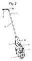
本発明の手術器具の概略構成が、図1から図3で説明されている。かくして、その手術器具は、
− 縦軸線に沿って伸びる伸長アーム3であって、縦軸線と直交した枢軸線回りの枢動継手を形成する手段にて当該伸長アーム3の遠位端部の所に取り付けられた遠位側部材30を有する伸長アーム3と、
− 枢動継手と向かい合った自在継手を形成する手段を備えた、伸長アーム3と同軸な回転シャフト4と、
− 回転シャフト4の遠位端部の所に固締され、伸長アーム3の遠位側部材30上に、遠位側部材30の延長上で回転可能に取り付けられた遠位側ツール5であって、当該遠位側ツール5が互いに別個の独立した2つの回転自由度を有し、一方の自由度が枢軸線回りのもので、他方の自由度が当該遠位側ツール自体の軸線と共線をなす軸線回りのものであるような遠位側ツール5(例えば、鉗子)と、
− 伸長アーム3の近位端部上に、当該近位端部の延長上で取り付けられた作動ユニット2であって、当該作動ユニット2が、前記2つの回転自由度の少なくとも一方を通じて遠位側におけるツールの可動性、即ち遠位側ツールの動作を作動させるための電動化手段20を備えると共に、電動化手段20を使用者が制御するための制御手段21を更に備えている、作動ユニット2と、
− 作動ユニット2から延びるハンドル1と、
を備えている。A schematic configuration of the surgical instrument of the present invention is illustrated in FIGS. 1 to 3. Thus, the surgical instrument is
An
A
A
An
A handle 1 extending from the
It has.
ハンドル1がレバー11を備え、そのレバー11が、前記伸長アーム3および回転シャフト4の内部を同軸に伸びる作動ケーブルを介して、前記遠位側ツール5の作動のために遠位側ツール5と機械的に結合されているのが好ましい。 The handle 1 comprises a
但し、もう一つの実施形態によれば、ハンドル1は如何なるレバーも備えていない。そのような場合、作動ユニット2は、前記伸長アーム3および回転シャフト4の内部を同軸に伸びる作動ケーブルを介した前記遠位側ツール5の作動のための補足的な電動化手段を備えていてもよい。 However, according to another embodiment, the handle 1 does not comprise any lever. In such a case, the
ここで、慣用用語において、自在継手とは、2本のシャフト同士を連結するために用いられ、一方のシャフトが他方のシャフトに対してどのような角度位置にあっても、一方のシャフトの回転運動をもう一方のシャフトへ伝達できるように適合されている機械力学的な継手である。いくつかのタイプの自在継手が存在している。 Here, in common terminology, a universal joint is used to connect two shafts together, and one shaft can rotate at any angular position with respect to the other shaft. A mechanical joint that is adapted to transmit motion to the other shaft. There are several types of universal joints.
手術器具のためのそのような構成は直接的な伝達を可能とし、その直接的な伝達は、子の軸線の位置を変更したり、作動機構を再構成し、或いはクラッチシステムを用いたりすることなく、鉗子のそれ自体の軸線回りの無限回転を生じさせる。全ての回転が独立して維持および/または作動される。更に、必要ならば全ての回転を同時に作動させ得る。他方の回転に対して任意の動きを描いて進むために、回転を逆転させたり相殺したりする必要はない。このため、例えば縫合運動を実行する際の器具の簡単な制御を確保するように遠位側の動きが最適に選択される。 Such a configuration for a surgical instrument allows direct transmission, which may change the position of the child axis, reconfigure the actuation mechanism, or use a clutch system. Rather, it causes infinite rotation about the axis of the forceps itself. All rotations are maintained and / or activated independently. Furthermore, if necessary, all rotations can be activated simultaneously. There is no need to reverse or cancel the rotation in order to draw an arbitrary movement relative to the other rotation. For this reason, for example, the distal movement is optimally selected so as to ensure simple control of the instrument when performing the suturing movement.
回転シャフトの自在継手は、例えば可撓性駆動スリーブを備えていてもよい。そのスリーブは、縦軸線に従う捩り応力に関しては剛性であることが好ましいが、縦軸線に垂直な如何なる軸線に従う捩り応力に関しても可撓性で弾性変形可能である。そのような構成の詳細な説明について、当業者は特許文献9(WO2010112608)として公開されたPCT出願を参照してもよく、当該出願の内容は本明細書に援用される。 The universal joint of the rotating shaft may comprise a flexible drive sleeve, for example. The sleeve is preferably rigid with respect to torsional stress along the longitudinal axis, but is flexible and elastically deformable with respect to torsional stress along any axis perpendicular to the longitudinal axis. For a detailed description of such a configuration, those skilled in the art may refer to a PCT application published as Patent Document 9 (WO2010112608), the contents of which are incorporated herein.
これに代えて、自在継手はカルダン継手を備えていてもよい。そのような構成の詳細な説明について、当業者は特許文献10(WO2010112609)として公開されたPCT出願を参照してもよく、当該出願の内容は本明細書に援用される。基本的に、カルダン継手は、中央要素の両側に取り付けられた2つの端部要素を備えた機械的な連結システムからなる。各端部要素は、中央要素と枢動継手をなして取り付けられる。中央要素における2つの枢動継手の軸線同士は、互いに垂直となっている。伸長アームの遠位側部材を形成するための直列に取り付けられた複数の連結要素と組み合わせる自在継手として、カルダン継手を用いることによって、手術器具の製造が大幅に単純化される。 Instead, the universal joint may include a cardan joint. For a detailed description of such a configuration, those skilled in the art may refer to the PCT application published as Patent Document 10 (WO2010112609), the contents of which are incorporated herein. Basically, a cardan joint consists of a mechanical coupling system with two end elements mounted on both sides of the central element. Each end element is mounted in a pivot joint with the central element. The axes of the two pivot joints in the central element are perpendicular to each other. By using a cardan joint as a universal joint in combination with a plurality of connecting elements mounted in series to form the distal member of the extension arm, the manufacture of the surgical instrument is greatly simplified.
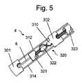
図4から図9は、遠位側部材を形成するための直列に取り付けられた連結要素と組み合わせる自在継手としてカルダン継手が用いられる、手術器具の特定の実施形態を示している。ここでは伸長アーム3が、枢動機能を作り出す複数の連結要素を備えている。それらの枢動要素の組は、中空の椎体の組と同様なものとすることができる。それらの椎体はそれぞれ、伸長アームの枢軸線に垂直な軸線回りの枢動継手にて、前の椎体に取り付けられている。正確には、伸長アーム3は、枢動継手(総合的枢動継手とも呼ばれる)を形成する5つの連結要素(301,302,303,304,305)を伴った遠位側部材30を備えている。伸長アーム3は中空であり、遠位側に中空の基部連結要素301を備えている。その基部連結要素301は、1組の枢動ラグ(雌側のみ)を備え、それらのラグが、伸長アーム3の遠位端部31の方向へ延びて、伸長アーム3の縦軸線に略垂直な軸線310を画成するように互いに対向している。伸長アーム3は更に、中空の中間連結要素(302,303,304)を備えている。それらの連結要素は、当該中間連結要素(302,303,304)の延長部をなして延びる2つのラグを備えている。それらのラグは、基部連結要素301の軸線310と平行で各中間連結要素(302,303,304)の遠位端部の所に置かれた軸線の回りの回転を可能とするように、互いに対向している。中間連結要素302は、基部連結要素301上に、軸線310に対して回転できるように取り付けられている。かくして中間連結要素302は、第1の有限枢動継手(連結要素の形態が枢動の範囲を自然に制限するため、くさび形枢動継手とも呼ばれる)を形成する。同様に、中間連結要素(302,303,304)は、軸線310と平行な軸線に対して相互に回転できるように取り付けられ、かくして第2および第3の有限枢動継手を形成する。伸長アーム3は更に、中空の端部連結要素305を備えている。同様に、端部連結要素305は、最後の中間連結要素304上に、軸線310と平行な軸線に対して回転できるように取り付けられている。かくして端部連結要素305は、第4の有限枢動継手を形成する。この端部連結要素305は、伸長アーム3の遠位端部を形成する。一連の有限枢動継手は、総合的枢動継手に対応するところの、本体全体に関しての累積的な枢動を作り出す。全体の屈曲角が、連結要素の各対同士の間における回転角の総和となるように、全ての枢動継手の軸線310同士が平行になっている。また、枢動の軸線310の両側に位置する2本のケーブル(312,314)がスライドするのを可能とするように、各椎体が穿孔されている。それらのケーブル(312,314)は、最後の椎体に取り付けられて、他の各椎体の開口内でスライドする。これにより、2本のケーブル(312,314)の一方ないし他方を引っ張ることによって、全ての枢軸を取付け後に作動させる、従って曲がらせることが可能となる。 FIGS. 4-9 illustrate a particular embodiment of a surgical instrument in which a cardan joint is used as a universal joint in combination with a serially attached coupling element to form a distal member. Here, the
手術器具は、伸長アーム3と略同軸に取り付けられた、伸長アーム3内で当該伸長アーム3の近位端部から基部連結要素301の近位側部分まで伸びる回転シャフト4を備えている。回転シャフト4は、その遠位端部の所に、様々な連結要素によって形成される空洞内を伸びた自在継手を形成する手段を備えている。この自在継手を形成する手段は、少なくとも1つのカルダン継手を備えている。自在継手を形成する手段は、少なくとも2つのカルダン継手を備えていることが好ましい。全範囲の動作(縦方向および半径方向の回転)を維持するためには、自在継手を形成する手段が各椎体(301,302,303,304,305)によって形成される枢軸線310と同じ数のカルダン継手を備えていることがより好ましい。従って、図4から図9に示す例では、4つのカルダン継手(320,330,340,350)が、異なる連結要素(301,302,303,304,305)同士の間に形成される各枢軸線310のレベルにそれぞれ配置されて、即ち対応する枢動継手に隣り合って設けられる。この実施形態の好適な態様によれば、各カルダン継手を画成する2つの枢動継手の軸線は、その継手が配置されるレベルにおいて枢軸線310と交差する。前に指摘したように、カルダン継手は、中央要素の両側に取り付けられた2つの端部要素を備える機械的連結システムであり、各端部要素は中央要素と枢動継手をなして取り付けられる。図4から図9に示す実施形態において、カルダン継手を形成する部品同士の間の枢動継手は、表面同士が重なり合うスライド式のガイドによって作られている。これを達成するために、例えば中央部品の表面上でスライドする表面を自らの端部に有した端部部品を設けることができる。これらの中央部品および端部部品は、スライド式のガイド手段を備えてもいる。 The surgical instrument includes a
遠位側ツール5(例えば、鉗子)は、端部連結要素305の遠位端部上に、その延長上で取り付けられる。遠位側ツール5は、端部連結要素305上に、当該要素の縦軸線回りに回転できるように取り付けられる。この遠位側ツール5は、伸長アーム3の内部を伸びる作動ケーブル6、例えばレバー11の作動を通じて引っ張られたときに鉗子5を閉じるように構成された作動ケーブル6によって作動されることが好ましい。カルダン継手による伝達装置を形成する各部品は、器具が曲げられていないときに器具の主軸線に沿う複数の貫通孔によって貫かれていることが、より好ましい。カルダン継手の部品に形成されるこれらの様々な孔によって、器具の遠位端部の所に配置された遠位側ツール5を作動させるように牽引力を伝達するための機械的な作動ケーブル6を貫通させることが可能となったり、信号、命令、または、単極および/もしくは双極電流の伝達のための電気ケーブル(図示せず)の余地あったりする。 A distal tool 5 (eg, forceps) is mounted on the distal end of the
90度に折れ曲がった状態を示す図8および図9、並びに、折れ曲がっていない状態を示す図6および図7を参照して、手術器具の操作を説明する。いずれの場合も、回転シャフト4の近位端部に加えられる回転運動370が、遠位側ツール5の回転運動371を引き起こす。この回転運動の完璧な伝達は、自在継手(例えば、カルダン継手320,330,340,350)を形成する手段によって確保される。これは、有限枢動継手の軸線310回りで転向する遠位端部の角偏向を問わない。折れ曲がった状態から折れ曲がっていない状態への(或いは、2つの異なる折れ曲がり状態同士の間での)移行は、ケーブル312,314のうち一方の、自らの軸線に従った並進移動を通じて行なわれる。これらのケーブルの一方を他方に対して相対的に並進させることによって、操作者が遠位側ツール5の曲がりを制御する。 The operation of the surgical instrument will be described with reference to FIGS. 8 and 9 showing the bent state at 90 degrees and FIGS. 6 and 7 showing the unfolded state. In any case, the
自らの縦軸線回りの回転対称性を有した手術器具は、通常は人間工学にかなった解剖学的な姿勢を可能とするものではなく、肘を上げて肩の外転させ続けることを使用者に強いるものである。これは、長期的には使用者にとっての苦痛に繋がり得る。かくして、手術器具には非軸対称な形状(即ち、当該器具の縦軸線回りの回転対称性を何ら有していない形状)を与えることが重要である。そのような形状は、より人間工学にかなった把持部材を使用者にもたらしてくれるのである。例えば、ピストルグリップ型のハンドルによって、使用者が肘を下げて、肩の外転や、人間工学にかなわない如何なる他の解剖学的な姿勢をも回避することが可能となる。そのハンドルによって、使用者は、把持能力を向上させ、かくして自らの挙動の更なる精確性を獲得することも可能となる。 Surgical instruments with rotational symmetry about their own vertical axis do not usually allow ergonomic anatomical posture, but users should continue to abduct the shoulders by raising their elbows It is a strong one. This can lead to pain for the user in the long run. Thus, it is important to give the surgical instrument a non-axisymmetric shape (ie, a shape that does not have any rotational symmetry about the longitudinal axis of the instrument). Such a shape provides the user with a more ergonomic gripping member. For example, a pistol grip handle allows the user to lower the elbow to avoid shoulder abduction or any other anatomical posture that is not ergonomic. The handle also allows the user to improve gripping ability and thus gain more accuracy of their behavior.
本発明の手術器具の特異性は、ハンドル1が非対称形状、好ましくはピストルグリップ型の形状を有すると共に、当該器具の縦軸線回りの枢動継手を形成する結合手段で作動ユニット2の延長上に取り付けられていることである。この結合手段はかくして、当該器具の縦軸線回りでの、作動ユニット2に対するハンドル1の相対的な回転を可能とするのである。 The peculiarity of the surgical instrument according to the invention is that the handle 1 has an asymmetrical shape, preferably a pistol grip type, and is on the extension of the
ハンドル1が作動ユニット2の延長上に取り付けられているという事実は、ハンドル1と作動ユニット2とが、特別な枢動継手を通じて一緒に結合された、互いに隣り合う2つの別個の部材である、ということを意味する。 The fact that the handle 1 is mounted on the extension of the
作動ユニット2は、電動化手段20と制御手段21との両者を取り囲むケーシングを備えているのが好ましい。かくしてハンドル1は、作動ユニット2のこのケーシング上に回転可能に取り付けられ、それにより作動ユニット2に対して係合解除可能なハンドル1を形成している。 The
更に、制御手段21は、ハンドル1が作動ユニット2に対して如何なる回転位置にあっても使用者によってハンドル1から操作できるように適合されている。ハンドル1が作動ユニット2に対して如何なる回転位置にあっても、当該ハンドル上の手の位置が同じ状態で遠位側の可動性を作動させることができるように、作動ユニット2の制御手段21は、器具の縦軸線回りの回転対称性を有していることが好ましい。 Furthermore, the control means 21 is adapted so that it can be operated from the handle 1 by the user when the handle 1 is in any rotational position with respect to the
作動ケーブル6を通じて遠位側ツール5を起動させるようにハンドル1上に配置されたレバー11もまた、使用者が自らのハンドル1の手の位置を変えることなくツールを作動させることもできるように、ハンドル1で向きを合わされる。 A
遠位側ツールにおける枢軸線回りの遠位側回転(即ち、器具の曲げ)は、0度から90度の間に限定されることが好ましい。それは、2つの極端な姿勢のうちの一方が、遠位側ツール5が伸長アーム3と一列に並ぶ非屈曲状態に対応するようなものである。かくして、外科医が例えば手術器具をカニューレから引き抜きたいと思うときには、その外科医は、ツール5が伸長アーム3と一列に並ぶと信じられる(もし曲げの範囲が−90度から90度の間であるならば、そうはならない)そのような極端な姿勢に置かれるように、当該ツール5を制御せねばならぬだけである。 The distal rotation about the pivot axis (ie, bending of the instrument) in the distal tool is preferably limited to between 0 and 90 degrees. It is such that one of the two extreme postures corresponds to the unbent state in which the
提案された、回転可能なハンドルを伴った特別な構成によって、如何なる(特に、遠位側ツールの)回転位置においても手術器具を使用することが可能となる。それにより、如何なる種類の外科手術に対しても外科医がくつろいで作業することが可能となるため、これは大きな利点である。 The proposed special configuration with a rotatable handle allows the surgical instrument to be used in any rotational position (especially the distal tool). This is a great advantage as it allows the surgeon to work comfortably for any kind of surgery.
図1および図2は、作動ユニット2に対して互いに反対向きのハンドル1の2つの回転位置を示している。図1に示す向きは、遠位側ツール5が手術器具の左手側を向いた状態で外科医が作業する必要のあるときの状況に対応している。遠位側ツール5が手術器具の右手側を向いた状態で外科医が作業せねばならない場合には、その外科医は、作動ユニット2に対してハンドル1を図2に示すように回転させねばならないだけである。制御手段21は、如何なるハンドル1の回転位置においても使用者によって操作できるように適合されているため、遠位側ツール5は容易に使用者の求めるような向きにされ得る。手術器具は、例えばツールを斜めに配置する必要があるときなどに、ハンドル1を作動ユニット2に対して如何なる回転位置にも置けるように適合されている。 1 and 2 show two rotational positions of the handle 1 opposite to each other with respect to the
作動ユニット2は、把握手段の設けられた外側ケーシングを備えていることが好ましい。その把握手段は、手によってか、任意の機械的な保持手段(ロボットなど)を使ってかのいずれかで、手術器具を掴んで保持できるように適合されている。従って使用時には、使用者は、作動ユニット2に対してハンドル1を係合解除して回転させつつ、(特に、伸長アーム3、回転シャフト4、および遠位側ツール5を含む)ツールユニットを何ら動かすことなく、作動ユニット2を所定位置に保持することができる。例えば、これにより外科医は、より快適な姿勢へとハンドル1を傾けて、より楽々と進行させることが可能となる。 The
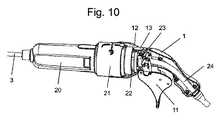
そのような構成は、作動ユニット2とツールユニット(かくして遠位側ツール5も)の両者が動かされるのを防ぎつつ、ハンドル1を極めて容易かつ迅速に係合解除させ得ることから、特に有利である。図10および図11は、結合手段が、作動ユニット2とハンドル1とにそれぞれ設けられた2つの輪形部分(12,22)を備えている、手術器具の特定の実施形態を示している。当該輪形部分同士は、例えば環状溝と対応する突条とを介して、互いに相対的な回転のために一緒に協働する。そのような結合手段にて、作動ユニット2の輪形部分22上でハンドル1が回転し得る。図10に示す実施形態においては、作動ユニット2が略円筒状の形状を有している。 Such a configuration is particularly advantageous because the handle 1 can be disengaged very easily and quickly while preventing both the
結合手段は、必要なときに作動ユニット2に対するハンドル1の回転を阻止することによってハンドルを所定位置にロックするためのクラッチ組立体13を備えていることが好ましい。これにより、外科医が手術器具を使用するときに、ハンドル1を作動ユニット2に対して所定位置に維持することが可能となる。それは外科医が、遠位側のツール5の可動性に加えて、縦軸線回りの軸回転を通じても器具を動かし得るようなものである。 The coupling means preferably comprises a
遠位側のツール5の可動性は電動化手段20によって作動されるが、その電動化手段20は、外科医の作業を容易にするだけでなく、その外科医の挙動を遙かに精確なものともしてくれる。但し、電動化手段20(例えば、モータなど)を有することによって、特に回転可能なハンドル1の配置や制御手段21の構成に関して、器具の構成がより複雑なものとなってしまう。 The mobility of the
第1の問題点は、各モータと、それらのモータの器具内での配置とに関するものである。作動ユニット2内での電動化手段の配置は、遠位側の可動性を作動させるための機械的要素の大部分を器具の回転不能な部分内に保ち、かくして機械的な複雑性を減少させるよう、特にハンドルの枢動関節結合を通じた複雑な動きの伝達を回避するように選択されている。但し電動化手段は、外部電源、および/または、ロジックや電力の伝達用の外部制御ユニットに対して電気的に接続されねばならない。それは、電気ケーブル24が必要となるようなものである。手術器具から伸びるそのような電気ケーブルによって外科医が悩まされるのを避けるように、そのケーブルは電動化手段20からハンドル1を通って作動ユニット2の外へと進んでいる。 The first problem relates to the motors and their placement in the appliance. The arrangement of the motorized means in the
この電気ケーブル24は、作動ユニット2内へと接続されるため、使用者用のハンドル1を貫通しつつ当該ハンドル1に対して回転できなければならない。この目的のために電気ケーブル24は、作動ユニット2に対してハンドル1が如何なる回転位置にあっても同じ姿勢を保てるように、作動ユニット2内へ軸線方向に接続されるべき、即ち縦軸線に沿って進むべきである。これにより、電気ケーブル24の、かくして電気的な接続の如何なる回転も回避されるが、これは手術器具の長寿命を確保するために重要なことである。 Since this
しかし、遠位側ツール5の操作を作動させるための(例えば、鉗子を開/閉させるための)機械的ケーブル6もまた、伝統的に軸線上にあるものである。電気的・機械的なケーブルを同軸に作ることができないため、遠位側ツール5の機械的な作動をハンドル1のレバー11から伝えるのに、軸線上にない機構が用いられる。この軸線上にない伝達機構23によって、電気ケーブル6の設置される区域内で、作動要素をレバー11から偏位させることが可能なる。 However, the
図10から図12に示す特定の実施形態によれば、そのような伝達機構23は、縦軸線から偏位して作動ユニット2内に配置された2本のロッド230を備えている。当該ロッド(230,231)は、縦軸線と平行な軸線に沿って並進可能となっている。 According to the particular embodiment shown in FIGS. 10 to 12, such a
これら2本のロッド(230,231)は、両者とも結合部材232に連結されているが、その結合部材232は、遠位側ツール5に直接的に結合された作動ケーブル6と連結されている。そのような結合部材232は、各ロッド(230,231)の並進運動を作動ケーブル6へ伝えると共に、作動ケーブル6の縦軸線回りの自由回転を可能とするように形成および配置されていることが好ましい。これにより、遠位側ツール5の自らの軸線と共線をなす軸線に沿った軸回転中における、作動ケーブル6のねじれが回避される。 These two rods (230, 231) are both connected to a connecting
軸線上にない伝達機構23は更に、作動ユニット2内に配置されてハンドル1のレバー11と結合された輪形部材234を備えている。そのような輪形部材234は、前記2本のロッド(230,231)それぞれの端部に固定されると共に、電気ケーブル24を取り囲んで縦軸線と平行な軸線に沿って並進可能となるように形成および配置されている。この輪形部材234は更に、レバー11の端部の所に設けられた少なくとも2本のピン236を挿入するための環状溝235を備えている。その結果、環状溝235およびピン236は、作動ユニット2に対するハンドル1およびレバー11の自由回転を可能としつつレバー11が輪形部材234およびロッド(230,231)へ並進運動を伝えることを可能とするカップリングを形成している。実際に、ハンドル1およびレバー11が回転するときには、2本のピン236が環状溝235内をスライドして、ハンドル1の回転が如何にあろうとも、それらのピン236が2本のロッドの軸線方向の並進を(かくして、遠位側ツールの作動をも)御するのである。この構成によって、ハンドル1の如何なる回転位置においてもレバー11が作動ケーブル6を並進させることが可能となる。 The
図12には、電気ケーブル24の両側を進む2本の縦方向ロッド(230,231)と、遠位側ツールの操作を作動させる作動ケーブル6との間の結合が示されている。上述したように、結合部材232のおかげで作動ケーブル6は、自らの縦軸線に沿って2本のロッド(230,231)に対して自由に回転することができる。そして作動ケーブル6は、軸線方向の回転シャフト4の内腔内を伸長アーム3と同軸に進み、最終的には遠位側部材の内部を進んで、遠位側ツールに固定されている。 FIG. 12 shows the coupling between the two longitudinal rods (230, 231) running on either side of the
上記の軸線上にない伝達機構は、専ら2本のロッドを備えるものでは必ずしもなく、作動ユニット2内に縦軸線から偏位して配置された1本のロッドしか備えなかったり、3本以上のロッドを備えたりするように適合されていてもよい、ということに留意されたい。 The transmission mechanism that is not on the axis is not necessarily provided with only two rods, but is provided with only one rod arranged in the
第2の問題点は、如何なるハンドル1の回転位置においても使用者の手が届かねばならない、電動化手段20の制御手段21に関するものである。その問題点への解決策は、器具の縦軸線に沿って実質的な軸対称性を有するように制御手段21を構成することである。かくして、このことが、如何なるハンドル1の回転位置においても使用者の手がその制御手段21に届くことを可能とする。 The second problem relates to the control means 21 of the motorized means 20 that must be reached by the user at any rotational position of the handle 1. A solution to that problem is to configure the control means 21 to have substantial axial symmetry along the longitudinal axis of the instrument. Thus, this allows the user's hand to reach the control means 21 at any rotational position of the handle 1.
図10に示すように、作動ユニット2は円筒形状を有しているのが好ましく、制御手段はこの場合、輪形の構成を有している。その制御手段は、例えば図11に示すような輪形のジョイスティック21を備えていてもよい。そのジョイスティック21によって、使用者の指による遠位側の可動性の制御、例えばハンドル1のピストルグリップ形状によるところの親指や人差指での制御が可能となる。 As shown in FIG. 10, the
制御手段21の輪形の構成は、様々な手法で実施することもできる。但し、器具の蒸気滅菌(滅菌のための最も信頼できる基準)に備えるためには、モータや電子機器が密封隔室内に置かれているのが好ましく、かくしてこれが制御手段を構成する手法に影響するのである。 The ring-shaped configuration of the control means 21 can be implemented by various methods. However, in order to prepare for the steam sterilization of the instrument (the most reliable standard for sterilization), it is preferable that the motor or the electronic device is placed in a sealed compartment, and this affects the method of constructing the control means. It is.
器具の完璧な密封を確保するためには、密封境界を通る機械的な動きを制限することが推奨される。かくして、非接触式の電子的な連絡、例えば密封隔室内に置かれた電子機器210と外部に置かれたスイッチ211との間の連絡のために適合された制御手段21を設けることが好ましい。 In order to ensure a perfect seal of the instrument, it is recommended to limit the mechanical movement through the sealing boundary. Thus, it is preferable to provide a control means 21 adapted for non-contact electronic communication, for example for communication between an
好適な実施形態によれば、スイッチ211は密封隔室の外部にある磁石2110を備え、電子機器210は密封隔室の内部にある複数のホールセンサ2100を備えている。その磁石2110は、使用者によって2方向へ横移動されるように構成されている。そのような磁石2110がホールセンサ2100の正面に置かれたとき、これらのホールセンサ2100によって磁界の変化が検出されて入力信号を生じさせ、この信号が電子機器によって処理されて、遠位側ツール5の遠位側の動きのために電動化手段20のモータを作動させる。According to a preferred embodiment, the
図13に示すように、指による制御システムは、内側ノブ2112上に並進するように取り付けられた、磁石2110付きの外側ノブ2111によって構成されている。前記内側ノブ2112は、軸線回りで回転するように作動ユニット2内に取り付けられている。内側ノブ2112は、作動ユニット2の密封隔室を形成している外側ハウジング2114上に、軸線回りで回転するように取り付けられているのが好ましい。 As shown in FIG. 13, the finger control system is comprised of an
磁石2110は、外側制御ノブ2111内に埋め込まれ、或いは外側制御ノブ2111に対して連結されている。前記外側ノブ2111は、使用者の指によって容易に動かすことができる。磁石2110は、保護用の樹脂やシリコーンの中にオーバーモールド成型することができる。 The
外側ノブ2111が内側ノブ2112に対して並進すると、内側ノブ2112に設けられた溝2113内を磁石2110がスライドする。外側ノブ2111が作動ユニット2上で軸線回りに回転すると、そのノブ2111は、内側ノブ2112を同じ動きをするように駆動する。 When the
好適な実施形態において、制御手段21の電子機器210は、8つのホールセンサ2100を備えている。これらのホールセンサのうち4つは、遠位側ツール5における遠位側の可動性のため、即ち、曲げ/戻し、および右/左回転の作動のために用いられる。4つの追加的なホールセンサは、組み合わされた動きを可能とするように対角に定置されている。 In the preferred embodiment, the
上述した構成の更にもう一つの利点は、手術器具の使用者が遠位側ツール5における遠位側の可動性を制御できるようにする、たった1つのジョイスティック、即ち外側ノブ2111があるだけ、ということである。更に、外側ノブ2111を介して、両方の動き(並進、軸回り回転)を互いに独立して、或いは同時に作動させることができる。 Yet another advantage of the above-described configuration is that there is only one joystick or
その上、ホールセンサ2100の使用は、それらが電位差計として、即ちオン/オフ・スイッチとしてだけではなく用いられる能力がある、という利点を有している。実際に、制御信号は、対応したホールセンサに対する磁石の距離によって左右されるのである。従って、磁石の移動量に比例した遠位側の可動性を有することが望まれるときには、各ホールセンサが電位差計として用いられるように電子機器が構成される。例えば、それにより使用者は、自らが遠位側ツールに与えたい動きの型式だけでなく、この動きの速度や、トルクなども制御することが可能となる。 Moreover, the use of
上述した電動化手段の制御手段は、多くのタイプの手術器具に用いることもできるであろう、ということに留意されたい。それは、対応する教示が、本明細書で提示された手術器具での使用には限定されないようなものである。 It should be noted that the control means of the motorized means described above could also be used for many types of surgical instruments. It is such that the corresponding teaching is not limited to use with the surgical instruments presented herein.
特に、その制御手段は、前記伸長アームおよび回転シャフト内を同軸に伸びる作動ケーブルを介して遠位側ツールを作動させるために当該遠位側ツールに機械的に結合されたレバーが設けられた、或いは設けられていないハンドル付きの手術器具に用いることができるであろう。そのようなレバーがハンドル上にない場合、作動ユニットは、前記伸長アームおよび回転シャフト内を同軸に伸びる作動ケーブルを介して遠位側ツールを作動させるための補足的な電動化手段を更に備えていてもよい。かくして対応する制御手段は、上述した最初の電動化手段の制御手段と関連させたり組み合わせたりすることができるであろう。 In particular, the control means is provided with a lever mechanically coupled to the distal tool for actuating the distal tool via an actuating cable extending coaxially within the extension arm and rotating shaft. Alternatively, it could be used for surgical instruments with handles that are not provided. If such a lever is not on the handle, the actuating unit further comprises supplemental motorized means for actuating the distal tool via an actuating cable extending coaxially within the extension arm and the rotating shaft. May be. Thus, the corresponding control means could be associated or combined with the control means of the first motorization means described above.
手術器具のもう一つの態様は、遠位側ツール5の曲げ/戻し、即ち縦軸線に直交した枢軸線回りでの遠位側ツールの回転運動を作動させるための作動ユニット内の機構に関するものである。 Another embodiment of the surgical instrument relates to a mechanism in the actuating unit for actuating the bending / returning of the
上述したように、遠位側ツール5は、遠位側部材30の枢動継手の所で伸長アーム3を曲げ/戻しすることによって、遠位側での向きが合わされる。そのような曲げ/戻しは、伸長アーム3に沿って進む2本の作動ケーブル(312,314)の存在によって可能とされている。正確には、作動ケーブルの一方314を引っ張ると同時に作動ケーブルの他方312を解放することによって曲げが達成されるのに対して、第2のケーブル312を引っ張って第1のケーブル314を解放することによって曲げの戻しが達成される。 As described above, the
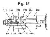
図15および図16に示すように、提案される特定の電動化作動機構は次のようなものである。即ち、電動化手段が駆動シャフト201付きのモータ200を備えており、そのシャフト201が、当該シャフト201を第1の作動ケーブル314および第2の作動ケーブル312とそれぞれ結合させるための第1の伝達部材202および第2の伝達部材203を有しているようなものである。その第1の伝達部材202は、駆動シャフト201の時計回りの回転時に、縦軸線と共線をなす第1の方向へ第1の作動ケーブル314を並進させるための手段を備えている。また、第2の伝達部材203は、駆動シャフト201の反時計回りの回転時に第1の方向へ第2の作動ケーブル312を並進させるための手段を備えている。 As shown in FIGS. 15 and 16, the proposed specific motorized operating mechanism is as follows. That is, the electrification means includes a
第1の伝達部材202および第2の伝達部材203が結合手段で駆動シャフト201に結合されていて、その結合手段が、モータ200の駆動シャフト201が回転したときにそれらの伝達部材(202,203)を縦軸線に沿って互いに反対の方向へ並進させられるように適合されているのが好ましい。 The
例えば、その結合手段は、駆動シャフト201の時計回りの回転時には、第1の伝達部材202を第1の方向へ並進させると共に、第2の伝達部材203を第1の方向とは反対の第2の方向へ並進させ、駆動シャフト201の反時計回りの回転時には、第2の伝達部材203を第1の方向へ並進させせると共に、第1の伝達部材202を第2の方向へ並進させられるように適合されている。 For example, the coupling means translates the
駆動シャフト201は、互いに反対向きのねじが切られた2つのねじ部(例えば、モータ出口の所では時計回りのねじで、軸線上のもっと遠くでは反時計回りのねじ)を備えていることが好ましい。モータ200の駆動シャフト201が回転したときに伝達部材(202,203)同士を互いに反対の方向へ並進させるように、各ねじ上に1つの伝達部材(202,203)が取り付けられる。2本の曲げ/戻しケーブル(312,314)のそれぞれが、伝達部材(202,203)のうちの1つに結合される。 The
2つのねじ同士が互いに反対向きなので、モータ200が一方向へ回転したときには、伝達部材(202,203)の一方が一方向へ並進し、かくして、例えば一方の作動ケーブル(312,314)を引っ張ると共に、他方が他方向へ並進して、他方のケーブル(312,314)を解放する。そうして、モータシャフトの軸回りの回転運動が、伸長アーム3の曲げや戻しを生じさせるのである。 Since the two screws are in opposite directions, when the
モータの一回転が両方の伝達部材(202,203)を(互いに反対方向へ)同じ距離だけ並進するように動かすこととなるように、2つのねじ同士が互いに同じピッチを有することもでき、或いは伝達部材(202,203)同士の互いに非対称な並進を生じさせるように、2つのねじ同士が互いに異なるピッチを有することもできるであろう。その互いに非対称な並進は、ケーブルの一方が、他方が解放される距離よりも長い距離だけ引っ張られることとなるようなものである。この後者の構成は、作動ケーブル(312,314)の一方が伸長アーム3の長い方の曲線に沿って進んでいるのに対して、他方が伸長アーム3の短い方の曲線に沿って進んでいるときに有用なものとなり得る。 The two screws can have the same pitch as each other, so that one revolution of the motor will move both transmission members (202, 203) to translate the same distance (in opposite directions), or It would also be possible for the two screws to have different pitches so as to cause asymmetric translation between the transmission members (202, 203). The asymmetric translation is such that one of the cables will be pulled a longer distance than the other is released. In this latter configuration, one of the actuating cables (312 and 314) runs along the longer curve of the
伝達部材(202,203)は更に、それらの伝達部材(202,203)が回転するのを防止するために設けられた案内シャフト204に沿って並進可能となっていてもよい。更に、そのような案内シャフト204上には、伝達部材(202,203)同士の間に配置された可動ばねを設けることができる。かくして、伝達部材(202,203)同士が互いに接近するときには可動ばねが圧縮される。それは、伝達部材(202,203)同士が互いに反対方向へ並進するのを当該ばねが助けるようなものである。 The transmission members (202, 203) may further be capable of translation along a
また、軟質または硬質の材料で形成された、伝達部材(202,203)同士の間で駆動シャフト201上に(好ましくは可動式に)取り付けられたカラーを設けることもできる。そのカラーは、伝達部材(202,203)同士が互いに向かって並進させられるときの受止め体を形成する。そのようなカラーはまた、駆動シャフト201の一端部もしくは他端部、または両端部に設けられて、伝達部材(202,203)が他方向へ並進させられるときの受止め体を形成することもできる。それに代えて、或いは、それに加えて、そのような(それらのような)カラーを、案内シャフト204上に同様に設けることもできるであろう。 It is also possible to provide a collar (preferably movable) mounted on the
好適な実施形態によれば、各作動ケーブルは、対応する伝達部材と協働するように適合された受け体を備えている。その協働は、当該伝達部材の一方向への並進が作動ケーブルを前記第1の方向へ並進させるのに対して、当該伝達部材の第1の方向とは反対のもう一方向への並進が作動ケーブルを解放するように行われる。 According to a preferred embodiment, each actuation cable comprises a receptacle that is adapted to cooperate with a corresponding transmission member. The cooperation is that translation of the transmission member in one direction translates the actuation cable in the first direction, whereas translation of the transmission member in another direction opposite the first direction. This is done to release the working cable.
各作動ケーブルは、ねじ部を有した円筒形要素のある端部(3140,3120)を備えているのが好ましい。当該ねじ部に取り付けられるねじ付きボルト(3141,3121)によって、受け体が形成される。更に当該ボルト(3141,3121)によって、作動ケーブルの長さの調節が可能となる。 Each actuating cable preferably has an end (3140, 3120) with a cylindrical element with a thread. The receiving body is formed by threaded bolts (3141, 3121) attached to the threaded portion. Furthermore, the length of the working cable can be adjusted by the bolts (3141, 3121).
もう一つの実施形態によれば、第1の伝達部材は、駆動シャフトの反時計回り回転時に第1の方向とは反対の第2の方向へ第1の作動ケーブルを並進させるための手段を備え、第2の伝達部材は、駆動シャフトの時計回り回転時に第2の方向へ第2の作動ケーブルを並進させるための手段を備えている。 According to another embodiment, the first transmission member comprises means for translating the first actuating cable in a second direction opposite to the first direction during counterclockwise rotation of the drive shaft. The second transmission member comprises means for translating the second actuation cable in the second direction during clockwise rotation of the drive shaft.
各作動ケーブルは、対応した伝達部材に対して固締される端部を有しているのが好ましい。 Each actuating cable preferably has an end that is secured to a corresponding transmission member.
電動化手段20は、遠位側ツール5自体の軸線と共線をなす軸線回りでの当該遠位側ツール5の回転を作動させるために、回転シャフト4の端部に固定されるもう一つの駆動シャフト206のある、もう一つのモータ205を備えていることが好ましい。 The motorizing means 20 is another fixed to the end of the
上述した曲げ/戻しの作動機構は、回転可能なピストルグリップ型ハンドル付きの手術器具に関して提示されてはいるが、その作動機構は、回転可能なハンドルを必ずしも有してはいない、例えば特許文献9(WO2010112608)や特許文献10(WO2010112609)で説明されているような手術器具などの、アームの回転を制御するための2本の作動ケーブルを用いる他の如何なるタイプの手術器具においても用いることができるであろう、ということに留意されたい。 Although the above-described bending / returning actuation mechanism has been presented for a surgical instrument with a rotatable pistol grip handle, the actuation mechanism does not necessarily have a rotatable handle, for example, US Pat. (WO2010112608) and Patent Document 10 (WO2010112609) can be used in any other type of surgical instrument that uses two actuating cables to control the rotation of the arm, such as the surgical instrument described in US Pat. Note that it will be.
提案された作動機構は、製造するのが非常に簡単なことから、極めて有利である。つまり、その作動機構は、両方の作動ケーブル(312,314)を作動させるための1つだけのモータを備えているのである。これは、特に作動ユニットの、かくして手術器具のコンパクト性に関して優れた長所となっている。その作動機構は、より廉価で簡単に製造できるだけでなく、遠位側ツールの曲げ/戻しのより精確な制御をも可能とするのである。 The proposed actuation mechanism is very advantageous because it is very simple to manufacture. That is, the operating mechanism includes only one motor for operating both operating cables (312, 314). This is an excellent advantage, especially with regard to the compactness of the surgical instrument, especially of the operating unit. The actuation mechanism is not only cheaper and easier to manufacture, but also allows more precise control of the bending / returning of the distal tool.
Claims (13)
Translated fromJapanese− 前記枢動継手と向かい合った自在継手を形成する手段を備えた、前記伸長アーム(3)と同軸な回転シャフト(4)と、
− 前記回転シャフト(4)の遠位端部の所に固締され、前記伸長アーム(3)の前記遠位側部材(30)上に、前記遠位側部材(30)の延長上で回転可能に取り付けられた遠位側ツール(5)であって、当該遠位側ツール(5)が互いに別個の独立した2つの回転自由度を有し、一方の自由度が前記枢軸線回りのもので、他方の自由度が当該遠位側ツール(5)自体の軸線と共線をなす軸線回りのものであるような遠位側ツール(5)と、
− 前記伸長アーム(3)の近位端部上に、当該近位端部の延長上で取り付けられた作動ユニット(2)であって、当該作動ユニット(2)が、前記2つの回転自由度の少なくとも一方を通じて前記遠位側ツール(5)の動作を作動させるための電動化手段(20)を備えると共に、前記電動化手段(20)を使用者が制御するための制御手段(21)を更に備えている、作動ユニット(2)と、
− 前記作動ユニット(2)から延びると共に、レバー(11)を備え、当該レバー(11)は、前記伸長アーム(3)および回転シャフト(4)の内部を同軸に伸びる作動ケーブル(6)を介して、前記遠位側ツール(5)の作動のために前記遠位側ツール(5)と機械的に結合されている、ハンドル(1)と、
を備えた手術器具において、
前記ハンドル(1)は、非軸対称形状を有すると共に、当該ハンドル(1)を前記作動ユニット(2)に対して前記縦軸線回りに回転可能とする結合手段(12,22)にて、前記作動ユニット(2)上に、前記作動ユニット(2)の延長上で取り付けられており、前記作動ユニット(2)は、前記電動化手段(20)および前記制御手段(21)の両方を収容するためのケーシングを備え、前記制御手段(21)は、前記電動化手段の作動用の電子部品(210)と、使用者が前記電子部品を制御するためのスイッチ(211)とを備え、前記スイッチ(211)は、前記ケーシング上に配置された外側スイッチ要素(2111)を含み、前記ケーシングは、前記ハンドル(1)および前記作動ユニット(2)を相対的に回転させつつ、当該ケーシングを使用者の手またはロボットが把持することができるように形成されていることを特徴とする手術器具。An extension arm (3) extending along a longitudinal axis, attached at the distal end of the extension arm (3) by means of forming a pivot joint about a pivot perpendicular to the longitudinal axis An elongated arm (3) having a distal member (30) formed;
A rotating shaft (4) coaxial with the extension arm (3), comprising means for forming a universal joint facing the pivot joint;
-Clamped at the distal end of the rotating shaft (4) and rotated on the distal member (30) of the extension arm (3) on an extension of the distal member (30) A detachably attached distal tool (5), the distal tool (5) having two independent and independent rotational degrees of freedom, one degree of freedom about the pivot axis A distal tool (5) in which the other degree of freedom is about an axis collinear with the axis of the distal tool (5) itself;
An actuating unit (2) mounted on the extension of the proximal end on the proximal end of the extension arm (3), the actuating unit (2) having the two rotational degrees of freedom; Motorized means (20) for actuating the movement of the distal tool (5) through at least one of the control means (21) and a control means (21) for the user to control the motorized means (20) An actuating unit (2) further comprising:
-Extending from the actuating unit (2) and provided with a lever (11), said lever (11) via an actuating cable (6) extending coaxially within the extension arm (3) and the rotating shaft (4). A handle (1) mechanically coupled to the distal tool (5) for actuation of the distal tool (5);
In a surgical instrument with
The handle (1) has a non-axisymmetric shape, and the coupling means (12, 22) enables the handle (1) to rotate about the longitudinal axis with respect to the operating unit (2). Mounted on the operating unit (2) on the extension of the operating unit (2), the operating unit (2) houses both the motorization means (20) and the control means (21). The control means (21) includes an electronic component (210) for operating the motorized means, and a switch (211) for a user to control the electronic component.(211), prior SL includes an outer switch element disposed on the casing (2111), said casing, said handle (1) and the while operating units (2) are relatively rotated, those Surgical instruments the user's hand or robot casing, characterized in that it is formed so that it can be gripped.
− 前記縦軸線から偏位して前記作動ユニット(2)内に配置され、前記縦軸線と平行な軸線に沿って並進可能な少なくとも1本のロッド(230,231)と、
− 前記ロッド(230,231)の並進運動を前記作動ケーブル(6)へ伝えると共に前記作動ケーブル(6)の前記縦軸線回りの自由回転を可能とするように形成および配置された、前記ロッド(230,231)と前記作動ケーブル(6)との間の結合部材(232)と、
− 前記作動ユニット内に配置されて前記ハンドル(1)の前記レバー(11)と結合され、前記ロッド(230,231)の端部に固定されると共に、前記電気ケーブル(24)を取り囲んで前記縦軸線と平行な軸線に沿って並進可能となるように構成された輪形部材(234)と、
を備え、
− 前記輪形部材(234)は、前記レバー(11)の端部の所に設けられた少なくとも2本のピン(236)を挿入するための環状溝(235)を更に備え、前記環状溝(235)およびピン(236)は、前記作動ユニット(2)に対する前記ハンドル(1)およびレバー(11)の自由回転を可能としつつ前記レバー(11)が前記輪形部材(234)およびロッド(230,231)を並進させることを可能とするカップリングを形成している、請求項2記載の手術器具。The transmission mechanism (23)
-At least one rod (230, 231) arranged in the actuating unit (2) offset from the longitudinal axis and translatable along an axis parallel to the longitudinal axis;
The rod (230) formed and arranged to transmit the translational movement of the rod (230, 231) to the actuation cable (6) and to allow free rotation of the actuation cable (6) about the longitudinal axis; 230, 231) and the actuating cable (6) coupling member (232);
-Disposed in the actuating unit and coupled to the lever (11) of the handle (1), fixed to the end of the rod (230, 231) and surrounding the electrical cable (24); An annular member (234) configured to be translatable along an axis parallel to the longitudinal axis;
With
The annular member (234) further comprises an annular groove (235) for inserting at least two pins (236) provided at the end of the lever (11), the annular groove (235); ) And the pin (236) allow the handle (1) and the lever (11) to freely rotate with respect to the operating unit (2), while the lever (11) has the ring-shaped member (234) and the rod (230, 231) The surgical instrument according to claim 2, forming a coupling that allows translation of
Applications Claiming Priority (7)
| Application Number | Priority Date | Filing Date | Title |
|---|---|---|---|
| US201161527519P | 2011-08-25 | 2011-08-25 | |
| US61/527,519 | 2011-08-25 | ||
| EP11306066.9 | 2011-08-26 | ||
| EP11306065.1 | 2011-08-26 | ||
| EP11306066 | 2011-08-26 | ||
| EP11306065 | 2011-08-26 | ||
| PCT/EP2012/066494WO2013026920A1 (en) | 2011-08-25 | 2012-08-24 | Surgical instrument with disengageable handle |
Publications (2)
| Publication Number | Publication Date |
|---|---|
| JP2014529436A JP2014529436A (en) | 2014-11-13 |
| JP5859650B2true JP5859650B2 (en) | 2016-02-10 |
Family
ID=47745977
Family Applications (2)
| Application Number | Title | Priority Date | Filing Date |
|---|---|---|---|
| JP2014526508AExpired - Fee RelatedJP5859650B2 (en) | 2011-08-25 | 2012-08-24 | Surgical instrument with disengageable handle |
| JP2014526509AExpired - Fee RelatedJP5615994B1 (en) | 2011-08-25 | 2012-08-24 | Actuating knob for surgical instruments |
Family Applications After (1)
| Application Number | Title | Priority Date | Filing Date |
|---|---|---|---|
| JP2014526509AExpired - Fee RelatedJP5615994B1 (en) | 2011-08-25 | 2012-08-24 | Actuating knob for surgical instruments |
Country Status (4)
| Country | Link |
|---|---|
| US (3) | US20140188091A1 (en) |
| EP (2) | EP2747676B1 (en) |
| JP (2) | JP5859650B2 (en) |
| WO (2) | WO2013026920A1 (en) |
Cited By (1)
| Publication number | Priority date | Publication date | Assignee | Title |
|---|---|---|---|---|
| KR20200030209A (en)* | 2018-09-12 | 2020-03-20 | 부산대학교 산학협력단 | Multi degree-of-freedom laparoscopic apparatus using disposable surgical robot tool |
Families Citing this family (492)
| Publication number | Priority date | Publication date | Assignee | Title |
|---|---|---|---|---|
| US11229472B2 (en)* | 2001-06-12 | 2022-01-25 | Cilag Gmbh International | Modular battery powered handheld surgical instrument with multiple magnetic position sensors |
| US20070084897A1 (en) | 2003-05-20 | 2007-04-19 | Shelton Frederick E Iv | Articulating surgical stapling instrument incorporating a two-piece e-beam firing mechanism |
| US9060770B2 (en) | 2003-05-20 | 2015-06-23 | Ethicon Endo-Surgery, Inc. | Robotically-driven surgical instrument with E-beam driver |
| US11890012B2 (en) | 2004-07-28 | 2024-02-06 | Cilag Gmbh International | Staple cartridge comprising cartridge body and attached support |
| US11998198B2 (en) | 2004-07-28 | 2024-06-04 | Cilag Gmbh International | Surgical stapling instrument incorporating a two-piece E-beam firing mechanism |
| US9072535B2 (en) | 2011-05-27 | 2015-07-07 | Ethicon Endo-Surgery, Inc. | Surgical stapling instruments with rotatable staple deployment arrangements |
| US8215531B2 (en) | 2004-07-28 | 2012-07-10 | Ethicon Endo-Surgery, Inc. | Surgical stapling instrument having a medical substance dispenser |
| US11246590B2 (en) | 2005-08-31 | 2022-02-15 | Cilag Gmbh International | Staple cartridge including staple drivers having different unfired heights |
| US7934630B2 (en) | 2005-08-31 | 2011-05-03 | Ethicon Endo-Surgery, Inc. | Staple cartridges for forming staples having differing formed staple heights |
| US10159482B2 (en) | 2005-08-31 | 2018-12-25 | Ethicon Llc | Fastener cartridge assembly comprising a fixed anvil and different staple heights |
| US11484312B2 (en) | 2005-08-31 | 2022-11-01 | Cilag Gmbh International | Staple cartridge comprising a staple driver arrangement |
| US9237891B2 (en) | 2005-08-31 | 2016-01-19 | Ethicon Endo-Surgery, Inc. | Robotically-controlled surgical stapling devices that produce formed staples having different lengths |
| US7669746B2 (en) | 2005-08-31 | 2010-03-02 | Ethicon Endo-Surgery, Inc. | Staple cartridges for forming staples having differing formed staple heights |
| US20070106317A1 (en) | 2005-11-09 | 2007-05-10 | Shelton Frederick E Iv | Hydraulically and electrically actuated articulation joints for surgical instruments |
| US8820603B2 (en) | 2006-01-31 | 2014-09-02 | Ethicon Endo-Surgery, Inc. | Accessing data stored in a memory of a surgical instrument |
| US11793518B2 (en) | 2006-01-31 | 2023-10-24 | Cilag Gmbh International | Powered surgical instruments with firing system lockout arrangements |
| US11278279B2 (en) | 2006-01-31 | 2022-03-22 | Cilag Gmbh International | Surgical instrument assembly |
| US20110024477A1 (en) | 2009-02-06 | 2011-02-03 | Hall Steven G | Driven Surgical Stapler Improvements |
| US11224427B2 (en) | 2006-01-31 | 2022-01-18 | Cilag Gmbh International | Surgical stapling system including a console and retraction assembly |
| US7753904B2 (en) | 2006-01-31 | 2010-07-13 | Ethicon Endo-Surgery, Inc. | Endoscopic surgical instrument with a handle that can articulate with respect to the shaft |
| US20120292367A1 (en) | 2006-01-31 | 2012-11-22 | Ethicon Endo-Surgery, Inc. | Robotically-controlled end effector |
| US8186555B2 (en) | 2006-01-31 | 2012-05-29 | Ethicon Endo-Surgery, Inc. | Motor-driven surgical cutting and fastening instrument with mechanical closure system |
| US7845537B2 (en) | 2006-01-31 | 2010-12-07 | Ethicon Endo-Surgery, Inc. | Surgical instrument having recording capabilities |
| US8708213B2 (en) | 2006-01-31 | 2014-04-29 | Ethicon Endo-Surgery, Inc. | Surgical instrument having a feedback system |
| US20110295295A1 (en) | 2006-01-31 | 2011-12-01 | Ethicon Endo-Surgery, Inc. | Robotically-controlled surgical instrument having recording capabilities |
| US8236010B2 (en) | 2006-03-23 | 2012-08-07 | Ethicon Endo-Surgery, Inc. | Surgical fastener and cutter with mimicking end effector |
| US8992422B2 (en) | 2006-03-23 | 2015-03-31 | Ethicon Endo-Surgery, Inc. | Robotically-controlled endoscopic accessory channel |
| US8322455B2 (en) | 2006-06-27 | 2012-12-04 | Ethicon Endo-Surgery, Inc. | Manually driven surgical cutting and fastening instrument |
| US10568652B2 (en) | 2006-09-29 | 2020-02-25 | Ethicon Llc | Surgical staples having attached drivers of different heights and stapling instruments for deploying the same |
| US7506791B2 (en) | 2006-09-29 | 2009-03-24 | Ethicon Endo-Surgery, Inc. | Surgical stapling instrument with mechanical mechanism for limiting maximum tissue compression |
| US11980366B2 (en) | 2006-10-03 | 2024-05-14 | Cilag Gmbh International | Surgical instrument |
| US8652120B2 (en) | 2007-01-10 | 2014-02-18 | Ethicon Endo-Surgery, Inc. | Surgical instrument with wireless communication between control unit and sensor transponders |
| US8684253B2 (en) | 2007-01-10 | 2014-04-01 | Ethicon Endo-Surgery, Inc. | Surgical instrument with wireless communication between a control unit of a robotic system and remote sensor |
| US8632535B2 (en) | 2007-01-10 | 2014-01-21 | Ethicon Endo-Surgery, Inc. | Interlock and surgical instrument including same |
| US11291441B2 (en) | 2007-01-10 | 2022-04-05 | Cilag Gmbh International | Surgical instrument with wireless communication between control unit and remote sensor |
| US11039836B2 (en) | 2007-01-11 | 2021-06-22 | Cilag Gmbh International | Staple cartridge for use with a surgical stapling instrument |
| US20080169333A1 (en) | 2007-01-11 | 2008-07-17 | Shelton Frederick E | Surgical stapler end effector with tapered distal end |
| US7673782B2 (en) | 2007-03-15 | 2010-03-09 | Ethicon Endo-Surgery, Inc. | Surgical stapling instrument having a releasable buttress material |
| US8893946B2 (en) | 2007-03-28 | 2014-11-25 | Ethicon Endo-Surgery, Inc. | Laparoscopic tissue thickness and clamp load measuring devices |
| US11564682B2 (en) | 2007-06-04 | 2023-01-31 | Cilag Gmbh International | Surgical stapler device |
| US8931682B2 (en) | 2007-06-04 | 2015-01-13 | Ethicon Endo-Surgery, Inc. | Robotically-controlled shaft based rotary drive systems for surgical instruments |
| US7753245B2 (en) | 2007-06-22 | 2010-07-13 | Ethicon Endo-Surgery, Inc. | Surgical stapling instruments |
| US11849941B2 (en) | 2007-06-29 | 2023-12-26 | Cilag Gmbh International | Staple cartridge having staple cavities extending at a transverse angle relative to a longitudinal cartridge axis |
| US9179912B2 (en) | 2008-02-14 | 2015-11-10 | Ethicon Endo-Surgery, Inc. | Robotically-controlled motorized surgical cutting and fastening instrument |
| US11986183B2 (en) | 2008-02-14 | 2024-05-21 | Cilag Gmbh International | Surgical cutting and fastening instrument comprising a plurality of sensors to measure an electrical parameter |
| JP5410110B2 (en) | 2008-02-14 | 2014-02-05 | エシコン・エンド−サージェリィ・インコーポレイテッド | Surgical cutting / fixing instrument with RF electrode |
| US7866527B2 (en) | 2008-02-14 | 2011-01-11 | Ethicon Endo-Surgery, Inc. | Surgical stapling apparatus with interlockable firing system |
| US8636736B2 (en) | 2008-02-14 | 2014-01-28 | Ethicon Endo-Surgery, Inc. | Motorized surgical cutting and fastening instrument |
| US7819298B2 (en) | 2008-02-14 | 2010-10-26 | Ethicon Endo-Surgery, Inc. | Surgical stapling apparatus with control features operable with one hand |
| US8758391B2 (en) | 2008-02-14 | 2014-06-24 | Ethicon Endo-Surgery, Inc. | Interchangeable tools for surgical instruments |
| US8573465B2 (en) | 2008-02-14 | 2013-11-05 | Ethicon Endo-Surgery, Inc. | Robotically-controlled surgical end effector system with rotary actuated closure systems |
| US9585657B2 (en) | 2008-02-15 | 2017-03-07 | Ethicon Endo-Surgery, Llc | Actuator for releasing a layer of material from a surgical end effector |
| US11272927B2 (en) | 2008-02-15 | 2022-03-15 | Cilag Gmbh International | Layer arrangements for surgical staple cartridges |
| US11648005B2 (en) | 2008-09-23 | 2023-05-16 | Cilag Gmbh International | Robotically-controlled motorized surgical instrument with an end effector |
| US9386983B2 (en) | 2008-09-23 | 2016-07-12 | Ethicon Endo-Surgery, Llc | Robotically-controlled motorized surgical instrument |
| US9005230B2 (en) | 2008-09-23 | 2015-04-14 | Ethicon Endo-Surgery, Inc. | Motorized surgical instrument |
| US8210411B2 (en) | 2008-09-23 | 2012-07-03 | Ethicon Endo-Surgery, Inc. | Motor-driven surgical cutting instrument |
| US8608045B2 (en) | 2008-10-10 | 2013-12-17 | Ethicon Endo-Sugery, Inc. | Powered surgical cutting and stapling apparatus with manually retractable firing system |
| US8517239B2 (en) | 2009-02-05 | 2013-08-27 | Ethicon Endo-Surgery, Inc. | Surgical stapling instrument comprising a magnetic element driver |
| US8444036B2 (en) | 2009-02-06 | 2013-05-21 | Ethicon Endo-Surgery, Inc. | Motor driven surgical fastener device with mechanisms for adjusting a tissue gap within the end effector |
| RU2525225C2 (en) | 2009-02-06 | 2014-08-10 | Этикон Эндо-Серджери, Инк. | Improvement of drive surgical suturing instrument |
| US11090104B2 (en) | 2009-10-09 | 2021-08-17 | Cilag Gmbh International | Surgical generator for ultrasonic and electrosurgical devices |
| US8220688B2 (en) | 2009-12-24 | 2012-07-17 | Ethicon Endo-Surgery, Inc. | Motor-driven surgical cutting instrument with electric actuator directional control assembly |
| US8851354B2 (en) | 2009-12-24 | 2014-10-07 | Ethicon Endo-Surgery, Inc. | Surgical cutting instrument that analyzes tissue thickness |
| US8783543B2 (en) | 2010-07-30 | 2014-07-22 | Ethicon Endo-Surgery, Inc. | Tissue acquisition arrangements and methods for surgical stapling devices |
| US9788834B2 (en) | 2010-09-30 | 2017-10-17 | Ethicon Llc | Layer comprising deployable attachment members |
| US9016542B2 (en) | 2010-09-30 | 2015-04-28 | Ethicon Endo-Surgery, Inc. | Staple cartridge comprising compressible distortion resistant components |
| US9629814B2 (en) | 2010-09-30 | 2017-04-25 | Ethicon Endo-Surgery, Llc | Tissue thickness compensator configured to redistribute compressive forces |
| US9351730B2 (en) | 2011-04-29 | 2016-05-31 | Ethicon Endo-Surgery, Llc | Tissue thickness compensator comprising channels |
| US9232941B2 (en) | 2010-09-30 | 2016-01-12 | Ethicon Endo-Surgery, Inc. | Tissue thickness compensator comprising a reservoir |
| US11925354B2 (en) | 2010-09-30 | 2024-03-12 | Cilag Gmbh International | Staple cartridge comprising staples positioned within a compressible portion thereof |
| US11812965B2 (en) | 2010-09-30 | 2023-11-14 | Cilag Gmbh International | Layer of material for a surgical end effector |
| US11298125B2 (en) | 2010-09-30 | 2022-04-12 | Cilag Gmbh International | Tissue stapler having a thickness compensator |
| US10945731B2 (en) | 2010-09-30 | 2021-03-16 | Ethicon Llc | Tissue thickness compensator comprising controlled release and expansion |
| US9386988B2 (en) | 2010-09-30 | 2016-07-12 | Ethicon End-Surgery, LLC | Retainer assembly including a tissue thickness compensator |
| US9364233B2 (en) | 2010-09-30 | 2016-06-14 | Ethicon Endo-Surgery, Llc | Tissue thickness compensators for circular surgical staplers |
| US12213666B2 (en) | 2010-09-30 | 2025-02-04 | Cilag Gmbh International | Tissue thickness compensator comprising layers |
| US8695866B2 (en) | 2010-10-01 | 2014-04-15 | Ethicon Endo-Surgery, Inc. | Surgical instrument having a power control circuit |
| EP2627278B1 (en) | 2010-10-11 | 2015-03-25 | Ecole Polytechnique Fédérale de Lausanne (EPFL) | Mechanical manipulator for surgical instruments |
| WO2013014621A2 (en) | 2011-07-27 | 2013-01-31 | Ecole Polytechnique Federale De Lausanne (Epfl) | Mechanical teleoperated device for remote manipulation |
| US12402960B2 (en) | 2010-10-11 | 2025-09-02 | Ecole Polytechnique Federale De Lausanne (Epfl) | Mechanical manipulator for surgical instruments |
| AU2012250197B2 (en) | 2011-04-29 | 2017-08-10 | Ethicon Endo-Surgery, Inc. | Staple cartridge comprising staples positioned within a compressible portion thereof |
| US11207064B2 (en) | 2011-05-27 | 2021-12-28 | Cilag Gmbh International | Automated end effector component reloading system for use with a robotic system |
| US9044230B2 (en) | 2012-02-13 | 2015-06-02 | Ethicon Endo-Surgery, Inc. | Surgical cutting and fastening instrument with apparatus for determining cartridge and firing motion status |
| BR112014024098B1 (en) | 2012-03-28 | 2021-05-25 | Ethicon Endo-Surgery, Inc. | staple cartridge |
| MX358135B (en) | 2012-03-28 | 2018-08-06 | Ethicon Endo Surgery Inc | Tissue thickness compensator comprising a plurality of layers. |
| JP6224070B2 (en) | 2012-03-28 | 2017-11-01 | エシコン・エンド−サージェリィ・インコーポレイテッドEthicon Endo−Surgery,Inc. | Retainer assembly including tissue thickness compensator |
| US9101358B2 (en) | 2012-06-15 | 2015-08-11 | Ethicon Endo-Surgery, Inc. | Articulatable surgical instrument comprising a firing drive |
| US20140001231A1 (en) | 2012-06-28 | 2014-01-02 | Ethicon Endo-Surgery, Inc. | Firing system lockout arrangements for surgical instruments |
| JP6290201B2 (en) | 2012-06-28 | 2018-03-07 | エシコン・エンド−サージェリィ・インコーポレイテッドEthicon Endo−Surgery,Inc. | Lockout for empty clip cartridge |
| US9282974B2 (en) | 2012-06-28 | 2016-03-15 | Ethicon Endo-Surgery, Llc | Empty clip cartridge lockout |
| BR112014032776B1 (en) | 2012-06-28 | 2021-09-08 | Ethicon Endo-Surgery, Inc | SURGICAL INSTRUMENT SYSTEM AND SURGICAL KIT FOR USE WITH A SURGICAL INSTRUMENT SYSTEM |
| US20140005718A1 (en) | 2012-06-28 | 2014-01-02 | Ethicon Endo-Surgery, Inc. | Multi-functional powered surgical device with external dissection features |
| US12383267B2 (en) | 2012-06-28 | 2025-08-12 | Cilag Gmbh International | Robotically powered surgical device with manually-actuatable reversing system |
| US9408606B2 (en) | 2012-06-28 | 2016-08-09 | Ethicon Endo-Surgery, Llc | Robotically powered surgical device with manually-actuatable reversing system |
| US9289256B2 (en) | 2012-06-28 | 2016-03-22 | Ethicon Endo-Surgery, Llc | Surgical end effectors having angled tissue-contacting surfaces |
| US11278284B2 (en) | 2012-06-28 | 2022-03-22 | Cilag Gmbh International | Rotary drive arrangements for surgical instruments |
| US9408622B2 (en) | 2012-06-29 | 2016-08-09 | Ethicon Endo-Surgery, Llc | Surgical instruments with articulating shafts |
| BR112015021082B1 (en) | 2013-03-01 | 2022-05-10 | Ethicon Endo-Surgery, Inc | surgical instrument |
| RU2672520C2 (en) | 2013-03-01 | 2018-11-15 | Этикон Эндо-Серджери, Инк. | Hingedly turnable surgical instruments with conducting ways for signal transfer |
| US10499932B2 (en)* | 2013-03-08 | 2019-12-10 | Arthrex, Inc. | Expandable reamer |
| US9629629B2 (en) | 2013-03-14 | 2017-04-25 | Ethicon Endo-Surgey, LLC | Control systems for surgical instruments |
| US9808244B2 (en) | 2013-03-14 | 2017-11-07 | Ethicon Llc | Sensor arrangements for absolute positioning system for surgical instruments |
| BR112015026109B1 (en) | 2013-04-16 | 2022-02-22 | Ethicon Endo-Surgery, Inc | surgical instrument |
| US9826976B2 (en) | 2013-04-16 | 2017-11-28 | Ethicon Llc | Motor driven surgical instruments with lockable dual drive shafts |
| US9775609B2 (en) | 2013-08-23 | 2017-10-03 | Ethicon Llc | Tamper proof circuit for surgical instrument battery pack |
| MX369362B (en) | 2013-08-23 | 2019-11-06 | Ethicon Endo Surgery Llc | Firing member retraction devices for powered surgical instruments. |
| JP6053701B2 (en)* | 2013-10-22 | 2016-12-27 | オリンパス株式会社 | Manipulator system control method and manipulator system |
| CA2931666C (en)* | 2014-01-13 | 2018-07-24 | Arley Perez III | Steerable surgical device with joystick |
| CN106659540B (en) | 2014-02-03 | 2019-03-05 | 迪斯塔莫申股份公司 | Mechanical teleoperated devices including interchangeable distal instruments |
| US9962161B2 (en) | 2014-02-12 | 2018-05-08 | Ethicon Llc | Deliverable surgical instrument |
| JP6462004B2 (en) | 2014-02-24 | 2019-01-30 | エシコン エルエルシー | Fastening system with launcher lockout |
| US10013049B2 (en) | 2014-03-26 | 2018-07-03 | Ethicon Llc | Power management through sleep options of segmented circuit and wake up control |
| BR112016021943B1 (en) | 2014-03-26 | 2022-06-14 | Ethicon Endo-Surgery, Llc | SURGICAL INSTRUMENT FOR USE BY AN OPERATOR IN A SURGICAL PROCEDURE |
| US12232723B2 (en) | 2014-03-26 | 2025-02-25 | Cilag Gmbh International | Systems and methods for controlling a segmented circuit |
| US10004497B2 (en) | 2014-03-26 | 2018-06-26 | Ethicon Llc | Interface systems for use with surgical instruments |
| US20150272580A1 (en) | 2014-03-26 | 2015-10-01 | Ethicon Endo-Surgery, Inc. | Verification of number of battery exchanges/procedure count |
| US10470768B2 (en) | 2014-04-16 | 2019-11-12 | Ethicon Llc | Fastener cartridge including a layer attached thereto |
| BR112016023825B1 (en) | 2014-04-16 | 2022-08-02 | Ethicon Endo-Surgery, Llc | STAPLE CARTRIDGE FOR USE WITH A SURGICAL STAPLER AND STAPLE CARTRIDGE FOR USE WITH A SURGICAL INSTRUMENT |
| CN106456159B (en) | 2014-04-16 | 2019-03-08 | 伊西康内外科有限责任公司 | Fastener Cartridge Assembly and Nail Retainer Cover Arrangement |
| CN106456176B (en) | 2014-04-16 | 2019-06-28 | 伊西康内外科有限责任公司 | Fastener Cartridge Including Extensions With Different Configurations |
| US10327764B2 (en) | 2014-09-26 | 2019-06-25 | Ethicon Llc | Method for creating a flexible staple line |
| US20150297225A1 (en) | 2014-04-16 | 2015-10-22 | Ethicon Endo-Surgery, Inc. | Fastener cartridges including extensions having different configurations |
| US10045781B2 (en) | 2014-06-13 | 2018-08-14 | Ethicon Llc | Closure lockout systems for surgical instruments |
| EP3185808B1 (en) | 2014-08-27 | 2022-02-23 | DistalMotion SA | Surgical system for microsurgical techniques |
| US11311294B2 (en) | 2014-09-05 | 2022-04-26 | Cilag Gmbh International | Powered medical device including measurement of closure state of jaws |
| US10135242B2 (en) | 2014-09-05 | 2018-11-20 | Ethicon Llc | Smart cartridge wake up operation and data retention |
| BR112017004361B1 (en) | 2014-09-05 | 2023-04-11 | Ethicon Llc | ELECTRONIC SYSTEM FOR A SURGICAL INSTRUMENT |
| US10105142B2 (en) | 2014-09-18 | 2018-10-23 | Ethicon Llc | Surgical stapler with plurality of cutting elements |
| US11523821B2 (en) | 2014-09-26 | 2022-12-13 | Cilag Gmbh International | Method for creating a flexible staple line |
| CN107427300B (en) | 2014-09-26 | 2020-12-04 | 伊西康有限责任公司 | Surgical suture buttresses and auxiliary materials |
| WO2016057989A2 (en)* | 2014-10-10 | 2016-04-14 | Transenterix, Inc. | Electromechanical surgical system |
| US10076325B2 (en) | 2014-10-13 | 2018-09-18 | Ethicon Llc | Surgical stapling apparatus comprising a tissue stop |
| US9924944B2 (en) | 2014-10-16 | 2018-03-27 | Ethicon Llc | Staple cartridge comprising an adjunct material |
| WO2016061291A1 (en) | 2014-10-18 | 2016-04-21 | Stryker European Holdings I, Llc | Surgical tool with a selectively bendable shaft and cables that selectively bend the shaft and that, when the shaft is bent, are in tension |
| US10517594B2 (en) | 2014-10-29 | 2019-12-31 | Ethicon Llc | Cartridge assemblies for surgical staplers |
| US11141153B2 (en) | 2014-10-29 | 2021-10-12 | Cilag Gmbh International | Staple cartridges comprising driver arrangements |
| US9844376B2 (en) | 2014-11-06 | 2017-12-19 | Ethicon Llc | Staple cartridge comprising a releasable adjunct material |
| US10736636B2 (en) | 2014-12-10 | 2020-08-11 | Ethicon Llc | Articulatable surgical instrument system |
| US10188385B2 (en) | 2014-12-18 | 2019-01-29 | Ethicon Llc | Surgical instrument system comprising lockable systems |
| US10085748B2 (en) | 2014-12-18 | 2018-10-02 | Ethicon Llc | Locking arrangements for detachable shaft assemblies with articulatable surgical end effectors |
| US9987000B2 (en) | 2014-12-18 | 2018-06-05 | Ethicon Llc | Surgical instrument assembly comprising a flexible articulation system |
| US9844374B2 (en) | 2014-12-18 | 2017-12-19 | Ethicon Llc | Surgical instrument systems comprising an articulatable end effector and means for adjusting the firing stroke of a firing member |
| US10117649B2 (en) | 2014-12-18 | 2018-11-06 | Ethicon Llc | Surgical instrument assembly comprising a lockable articulation system |
| US9943309B2 (en) | 2014-12-18 | 2018-04-17 | Ethicon Llc | Surgical instruments with articulatable end effectors and movable firing beam support arrangements |
| US9844375B2 (en) | 2014-12-18 | 2017-12-19 | Ethicon Llc | Drive arrangements for articulatable surgical instruments |
| MX389118B (en) | 2014-12-18 | 2025-03-20 | Ethicon Llc | SURGICAL INSTRUMENT WITH AN ANVIL THAT CAN BE SELECTIVELY MOVED ON A DISCRETE, NON-MOBILE AXIS RELATIVE TO A STAPLE CARTRIDGE. |
| EP3232951B1 (en) | 2014-12-19 | 2023-10-25 | DistalMotion SA | Surgical instrument with articulated end-effector |
| WO2016097871A1 (en) | 2014-12-19 | 2016-06-23 | Distalmotion Sa | Docking system for mechanical telemanipulator |
| EP3653145B1 (en) | 2014-12-19 | 2024-01-24 | DistalMotion SA | Reusable surgical instrument for minimally invasive procedures |
| WO2016097861A1 (en) | 2014-12-19 | 2016-06-23 | Distalmotion Sa | Sterile interface for articulated surgical instruments |
| WO2016097873A2 (en) | 2014-12-19 | 2016-06-23 | Distalmotion Sa | Articulated handle for mechanical telemanipulator |
| US10159483B2 (en) | 2015-02-27 | 2018-12-25 | Ethicon Llc | Surgical apparatus configured to track an end-of-life parameter |
| US9993258B2 (en)* | 2015-02-27 | 2018-06-12 | Ethicon Llc | Adaptable surgical instrument handle |
| US11154301B2 (en) | 2015-02-27 | 2021-10-26 | Cilag Gmbh International | Modular stapling assembly |
| US10180463B2 (en) | 2015-02-27 | 2019-01-15 | Ethicon Llc | Surgical apparatus configured to assess whether a performance parameter of the surgical apparatus is within an acceptable performance band |
| US9924961B2 (en) | 2015-03-06 | 2018-03-27 | Ethicon Endo-Surgery, Llc | Interactive feedback system for powered surgical instruments |
| US10441279B2 (en) | 2015-03-06 | 2019-10-15 | Ethicon Llc | Multiple level thresholds to modify operation of powered surgical instruments |
| JP2020121162A (en) | 2015-03-06 | 2020-08-13 | エシコン エルエルシーEthicon LLC | Time dependent evaluation of sensor data to determine stability element, creep element and viscoelastic element of measurement |
| US9901342B2 (en) | 2015-03-06 | 2018-02-27 | Ethicon Endo-Surgery, Llc | Signal and power communication system positioned on a rotatable shaft |
| US9993248B2 (en) | 2015-03-06 | 2018-06-12 | Ethicon Endo-Surgery, Llc | Smart sensors with local signal processing |
| US10045776B2 (en) | 2015-03-06 | 2018-08-14 | Ethicon Llc | Control techniques and sub-processor contained within modular shaft with select control processing from handle |
| US10245033B2 (en) | 2015-03-06 | 2019-04-02 | Ethicon Llc | Surgical instrument comprising a lockable battery housing |
| US10548504B2 (en) | 2015-03-06 | 2020-02-04 | Ethicon Llc | Overlaid multi sensor radio frequency (RF) electrode system to measure tissue compression |
| US10617412B2 (en) | 2015-03-06 | 2020-04-14 | Ethicon Llc | System for detecting the mis-insertion of a staple cartridge into a surgical stapler |
| US9808246B2 (en) | 2015-03-06 | 2017-11-07 | Ethicon Endo-Surgery, Llc | Method of operating a powered surgical instrument |
| US10687806B2 (en) | 2015-03-06 | 2020-06-23 | Ethicon Llc | Adaptive tissue compression techniques to adjust closure rates for multiple tissue types |
| US10433844B2 (en) | 2015-03-31 | 2019-10-08 | Ethicon Llc | Surgical instrument with selectively disengageable threaded drive systems |
| EP3280337B1 (en) | 2015-04-09 | 2019-11-13 | DistalMotion SA | Articulated hand-held instrument |
| US10568709B2 (en) | 2015-04-09 | 2020-02-25 | Distalmotion Sa | Mechanical teleoperated device for remote manipulation |
| US10154841B2 (en) | 2015-06-18 | 2018-12-18 | Ethicon Llc | Surgical stapling instruments with lockout arrangements for preventing firing system actuation when a cartridge is spent or missing |
| JP6602076B2 (en)* | 2015-07-14 | 2019-11-06 | 国立大学法人 東京医科歯科大学 | Forceps system |
| US10835249B2 (en) | 2015-08-17 | 2020-11-17 | Ethicon Llc | Implantable layers for a surgical instrument |
| US10980538B2 (en) | 2015-08-26 | 2021-04-20 | Ethicon Llc | Surgical stapling configurations for curved and circular stapling instruments |
| WO2017037532A1 (en) | 2015-08-28 | 2017-03-09 | Distalmotion Sa | Surgical instrument with increased actuation force |
| US10363036B2 (en) | 2015-09-23 | 2019-07-30 | Ethicon Llc | Surgical stapler having force-based motor control |
| US10327769B2 (en) | 2015-09-23 | 2019-06-25 | Ethicon Llc | Surgical stapler having motor control based on a drive system component |
| US10238386B2 (en) | 2015-09-23 | 2019-03-26 | Ethicon Llc | Surgical stapler having motor control based on an electrical parameter related to a motor current |
| US10085751B2 (en) | 2015-09-23 | 2018-10-02 | Ethicon Llc | Surgical stapler having temperature-based motor control |
| US10076326B2 (en) | 2015-09-23 | 2018-09-18 | Ethicon Llc | Surgical stapler having current mirror-based motor control |
| US10105139B2 (en) | 2015-09-23 | 2018-10-23 | Ethicon Llc | Surgical stapler having downstream current-based motor control |
| US10299878B2 (en) | 2015-09-25 | 2019-05-28 | Ethicon Llc | Implantable adjunct systems for determining adjunct skew |
| US10980539B2 (en) | 2015-09-30 | 2021-04-20 | Ethicon Llc | Implantable adjunct comprising bonded layers |
| US10478188B2 (en) | 2015-09-30 | 2019-11-19 | Ethicon Llc | Implantable layer comprising a constricted configuration |
| US10433846B2 (en) | 2015-09-30 | 2019-10-08 | Ethicon Llc | Compressible adjunct with crossing spacer fibers |
| US10194973B2 (en) | 2015-09-30 | 2019-02-05 | Ethicon Llc | Generator for digitally generating electrical signal waveforms for electrosurgical and ultrasonic surgical instruments |
| US11890015B2 (en) | 2015-09-30 | 2024-02-06 | Cilag Gmbh International | Compressible adjunct with crossing spacer fibers |
| US10368865B2 (en) | 2015-12-30 | 2019-08-06 | Ethicon Llc | Mechanisms for compensating for drivetrain failure in powered surgical instruments |
| US10265068B2 (en) | 2015-12-30 | 2019-04-23 | Ethicon Llc | Surgical instruments with separable motors and motor control circuits |
| US10292704B2 (en) | 2015-12-30 | 2019-05-21 | Ethicon Llc | Mechanisms for compensating for battery pack failure in powered surgical instruments |
| US11129670B2 (en) | 2016-01-15 | 2021-09-28 | Cilag Gmbh International | Modular battery powered handheld surgical instrument with selective application of energy based on button displacement, intensity, or local tissue characterization |
| US12193698B2 (en) | 2016-01-15 | 2025-01-14 | Cilag Gmbh International | Method for self-diagnosing operation of a control switch in a surgical instrument system |
| US11229471B2 (en) | 2016-01-15 | 2022-01-25 | Cilag Gmbh International | Modular battery powered handheld surgical instrument with selective application of energy based on tissue characterization |
| US11051840B2 (en) | 2016-01-15 | 2021-07-06 | Ethicon Llc | Modular battery powered handheld surgical instrument with reusable asymmetric handle housing |
| US10413291B2 (en) | 2016-02-09 | 2019-09-17 | Ethicon Llc | Surgical instrument articulation mechanism with slotted secondary constraint |
| US11213293B2 (en) | 2016-02-09 | 2022-01-04 | Cilag Gmbh International | Articulatable surgical instruments with single articulation link arrangements |
| BR112018016098B1 (en) | 2016-02-09 | 2023-02-23 | Ethicon Llc | SURGICAL INSTRUMENT |
| US11224426B2 (en) | 2016-02-12 | 2022-01-18 | Cilag Gmbh International | Mechanisms for compensating for drivetrain failure in powered surgical instruments |
| US10258331B2 (en) | 2016-02-12 | 2019-04-16 | Ethicon Llc | Mechanisms for compensating for drivetrain failure in powered surgical instruments |
| US10448948B2 (en) | 2016-02-12 | 2019-10-22 | Ethicon Llc | Mechanisms for compensating for drivetrain failure in powered surgical instruments |
| DE102016105789A1 (en)* | 2016-03-30 | 2017-10-05 | Aesculap Ag | Sensory encoder system |
| US10617413B2 (en) | 2016-04-01 | 2020-04-14 | Ethicon Llc | Closure system arrangements for surgical cutting and stapling devices with separate and distinct firing shafts |
| US10413297B2 (en) | 2016-04-01 | 2019-09-17 | Ethicon Llc | Surgical stapling system configured to apply annular rows of staples having different heights |
| US11607239B2 (en) | 2016-04-15 | 2023-03-21 | Cilag Gmbh International | Systems and methods for controlling a surgical stapling and cutting instrument |
| US10492783B2 (en) | 2016-04-15 | 2019-12-03 | Ethicon, Llc | Surgical instrument with improved stop/start control during a firing motion |
| US11179150B2 (en) | 2016-04-15 | 2021-11-23 | Cilag Gmbh International | Systems and methods for controlling a surgical stapling and cutting instrument |
| US10456137B2 (en) | 2016-04-15 | 2019-10-29 | Ethicon Llc | Staple formation detection mechanisms |
| US10357247B2 (en) | 2016-04-15 | 2019-07-23 | Ethicon Llc | Surgical instrument with multiple program responses during a firing motion |
| US10335145B2 (en) | 2016-04-15 | 2019-07-02 | Ethicon Llc | Modular surgical instrument with configurable operating mode |
| US10426467B2 (en) | 2016-04-15 | 2019-10-01 | Ethicon Llc | Surgical instrument with detection sensors |
| US10828028B2 (en) | 2016-04-15 | 2020-11-10 | Ethicon Llc | Surgical instrument with multiple program responses during a firing motion |
| US10405859B2 (en) | 2016-04-15 | 2019-09-10 | Ethicon Llc | Surgical instrument with adjustable stop/start control during a firing motion |
| US20170296173A1 (en) | 2016-04-18 | 2017-10-19 | Ethicon Endo-Surgery, Llc | Method for operating a surgical instrument |
| US10363037B2 (en) | 2016-04-18 | 2019-07-30 | Ethicon Llc | Surgical instrument system comprising a magnetic lockout |
| US11317917B2 (en) | 2016-04-18 | 2022-05-03 | Cilag Gmbh International | Surgical stapling system comprising a lockable firing assembly |
| US10905505B1 (en) | 2016-04-22 | 2021-02-02 | Memorial Sloan Kettering Cancer Center | Robotic surgical manipulation systems and methods |
| US10500000B2 (en) | 2016-08-16 | 2019-12-10 | Ethicon Llc | Surgical tool with manual control of end effector jaws |
| US11266430B2 (en) | 2016-11-29 | 2022-03-08 | Cilag Gmbh International | End effector control and calibration |
| US10695055B2 (en) | 2016-12-21 | 2020-06-30 | Ethicon Llc | Firing assembly comprising a lockout |
| US10758229B2 (en) | 2016-12-21 | 2020-09-01 | Ethicon Llc | Surgical instrument comprising improved jaw control |
| JP7010957B2 (en) | 2016-12-21 | 2022-01-26 | エシコン エルエルシー | Shaft assembly with lockout |
| US10813638B2 (en) | 2016-12-21 | 2020-10-27 | Ethicon Llc | Surgical end effectors with expandable tissue stop arrangements |
| US10980536B2 (en) | 2016-12-21 | 2021-04-20 | Ethicon Llc | No-cartridge and spent cartridge lockout arrangements for surgical staplers |
| US11134942B2 (en) | 2016-12-21 | 2021-10-05 | Cilag Gmbh International | Surgical stapling instruments and staple-forming anvils |
| US10898186B2 (en) | 2016-12-21 | 2021-01-26 | Ethicon Llc | Staple forming pocket arrangements comprising primary sidewalls and pocket sidewalls |
| CN110087565A (en) | 2016-12-21 | 2019-08-02 | 爱惜康有限责任公司 | Surgical stapling system |
| US10568625B2 (en) | 2016-12-21 | 2020-02-25 | Ethicon Llc | Staple cartridges and arrangements of staples and staple cavities therein |
| US20180168625A1 (en) | 2016-12-21 | 2018-06-21 | Ethicon Endo-Surgery, Llc | Surgical stapling instruments with smart staple cartridges |
| JP7010956B2 (en) | 2016-12-21 | 2022-01-26 | エシコン エルエルシー | How to staple tissue |
| JP6983893B2 (en) | 2016-12-21 | 2021-12-17 | エシコン エルエルシーEthicon LLC | Lockout configuration for surgical end effectors and replaceable tool assemblies |
| US20180168615A1 (en) | 2016-12-21 | 2018-06-21 | Ethicon Endo-Surgery, Llc | Method of deforming staples from two different types of staple cartridges with the same surgical stapling instrument |
| US11090048B2 (en) | 2016-12-21 | 2021-08-17 | Cilag Gmbh International | Method for resetting a fuse of a surgical instrument shaft |
| US10973516B2 (en) | 2016-12-21 | 2021-04-13 | Ethicon Llc | Surgical end effectors and adaptable firing members therefor |
| US10426471B2 (en) | 2016-12-21 | 2019-10-01 | Ethicon Llc | Surgical instrument with multiple failure response modes |
| US10582928B2 (en) | 2016-12-21 | 2020-03-10 | Ethicon Llc | Articulation lock arrangements for locking an end effector in an articulated position in response to actuation of a jaw closure system |
| MX2019007295A (en) | 2016-12-21 | 2019-10-15 | Ethicon Llc | Surgical instrument system comprising an end effector lockout and a firing assembly lockout. |
| US10485543B2 (en) | 2016-12-21 | 2019-11-26 | Ethicon Llc | Anvil having a knife slot width |
| JP2020501815A (en) | 2016-12-21 | 2020-01-23 | エシコン エルエルシーEthicon LLC | Surgical stapling system |
| US10542982B2 (en) | 2016-12-21 | 2020-01-28 | Ethicon Llc | Shaft assembly comprising first and second articulation lockouts |
| US11419606B2 (en) | 2016-12-21 | 2022-08-23 | Cilag Gmbh International | Shaft assembly comprising a clutch configured to adapt the output of a rotary firing member to two different systems |
| US11058503B2 (en) | 2017-05-11 | 2021-07-13 | Distalmotion Sa | Translational instrument interface for surgical robot and surgical robot systems comprising the same |
| USD879809S1 (en) | 2017-06-20 | 2020-03-31 | Ethicon Llc | Display panel with changeable graphical user interface |
| US11071554B2 (en) | 2017-06-20 | 2021-07-27 | Cilag Gmbh International | Closed loop feedback control of motor velocity of a surgical stapling and cutting instrument based on magnitude of velocity error measurements |
| US11517325B2 (en) | 2017-06-20 | 2022-12-06 | Cilag Gmbh International | Closed loop feedback control of motor velocity of a surgical stapling and cutting instrument based on measured displacement distance traveled over a specified time interval |
| US10813639B2 (en) | 2017-06-20 | 2020-10-27 | Ethicon Llc | Closed loop feedback control of motor velocity of a surgical stapling and cutting instrument based on system conditions |
| US10888321B2 (en) | 2017-06-20 | 2021-01-12 | Ethicon Llc | Systems and methods for controlling velocity of a displacement member of a surgical stapling and cutting instrument |
| US10624633B2 (en) | 2017-06-20 | 2020-04-21 | Ethicon Llc | Systems and methods for controlling motor velocity of a surgical stapling and cutting instrument |
| US10327767B2 (en) | 2017-06-20 | 2019-06-25 | Ethicon Llc | Control of motor velocity of a surgical stapling and cutting instrument based on angle of articulation |
| US10980537B2 (en) | 2017-06-20 | 2021-04-20 | Ethicon Llc | Closed loop feedback control of motor velocity of a surgical stapling and cutting instrument based on measured time over a specified number of shaft rotations |
| US10368864B2 (en) | 2017-06-20 | 2019-08-06 | Ethicon Llc | Systems and methods for controlling displaying motor velocity for a surgical instrument |
| US10307170B2 (en) | 2017-06-20 | 2019-06-04 | Ethicon Llc | Method for closed loop control of motor velocity of a surgical stapling and cutting instrument |
| US10779820B2 (en) | 2017-06-20 | 2020-09-22 | Ethicon Llc | Systems and methods for controlling motor speed according to user input for a surgical instrument |
| US10881396B2 (en) | 2017-06-20 | 2021-01-05 | Ethicon Llc | Surgical instrument with variable duration trigger arrangement |
| US11090046B2 (en) | 2017-06-20 | 2021-08-17 | Cilag Gmbh International | Systems and methods for controlling displacement member motion of a surgical stapling and cutting instrument |
| US10390841B2 (en) | 2017-06-20 | 2019-08-27 | Ethicon Llc | Control of motor velocity of a surgical stapling and cutting instrument based on angle of articulation |
| US10881399B2 (en) | 2017-06-20 | 2021-01-05 | Ethicon Llc | Techniques for adaptive control of motor velocity of a surgical stapling and cutting instrument |
| USD890784S1 (en) | 2017-06-20 | 2020-07-21 | Ethicon Llc | Display panel with changeable graphical user interface |
| USD879808S1 (en) | 2017-06-20 | 2020-03-31 | Ethicon Llc | Display panel with graphical user interface |
| US11382638B2 (en) | 2017-06-20 | 2022-07-12 | Cilag Gmbh International | Closed loop feedback control of motor velocity of a surgical stapling and cutting instrument based on measured time over a specified displacement distance |
| US11653914B2 (en) | 2017-06-20 | 2023-05-23 | Cilag Gmbh International | Systems and methods for controlling motor velocity of a surgical stapling and cutting instrument according to articulation angle of end effector |
| US10646220B2 (en) | 2017-06-20 | 2020-05-12 | Ethicon Llc | Systems and methods for controlling displacement member velocity for a surgical instrument |
| US10993716B2 (en) | 2017-06-27 | 2021-05-04 | Ethicon Llc | Surgical anvil arrangements |
| US10856869B2 (en) | 2017-06-27 | 2020-12-08 | Ethicon Llc | Surgical anvil arrangements |
| US10772629B2 (en) | 2017-06-27 | 2020-09-15 | Ethicon Llc | Surgical anvil arrangements |
| US11324503B2 (en) | 2017-06-27 | 2022-05-10 | Cilag Gmbh International | Surgical firing member arrangements |
| US11090049B2 (en) | 2017-06-27 | 2021-08-17 | Cilag Gmbh International | Staple forming pocket arrangements |
| US11266405B2 (en) | 2017-06-27 | 2022-03-08 | Cilag Gmbh International | Surgical anvil manufacturing methods |
| US11259805B2 (en) | 2017-06-28 | 2022-03-01 | Cilag Gmbh International | Surgical instrument comprising firing member supports |
| USD906355S1 (en) | 2017-06-28 | 2020-12-29 | Ethicon Llc | Display screen or portion thereof with a graphical user interface for a surgical instrument |
| US10716614B2 (en) | 2017-06-28 | 2020-07-21 | Ethicon Llc | Surgical shaft assemblies with slip ring assemblies with increased contact pressure |
| US11484310B2 (en) | 2017-06-28 | 2022-11-01 | Cilag Gmbh International | Surgical instrument comprising a shaft including a closure tube profile |
| US11246592B2 (en) | 2017-06-28 | 2022-02-15 | Cilag Gmbh International | Surgical instrument comprising an articulation system lockable to a frame |
| US10903685B2 (en) | 2017-06-28 | 2021-01-26 | Ethicon Llc | Surgical shaft assemblies with slip ring assemblies forming capacitive channels |
| US10758232B2 (en) | 2017-06-28 | 2020-09-01 | Ethicon Llc | Surgical instrument with positive jaw opening features |
| EP3420947B1 (en) | 2017-06-28 | 2022-05-25 | Cilag GmbH International | Surgical instrument comprising selectively actuatable rotatable couplers |
| US11564686B2 (en) | 2017-06-28 | 2023-01-31 | Cilag Gmbh International | Surgical shaft assemblies with flexible interfaces |
| USD869655S1 (en) | 2017-06-28 | 2019-12-10 | Ethicon Llc | Surgical fastener cartridge |
| USD851762S1 (en) | 2017-06-28 | 2019-06-18 | Ethicon Llc | Anvil |
| US10765427B2 (en) | 2017-06-28 | 2020-09-08 | Ethicon Llc | Method for articulating a surgical instrument |
| USD854151S1 (en) | 2017-06-28 | 2019-07-16 | Ethicon Llc | Surgical instrument shaft |
| US10211586B2 (en) | 2017-06-28 | 2019-02-19 | Ethicon Llc | Surgical shaft assemblies with watertight housings |
| US10898183B2 (en) | 2017-06-29 | 2021-01-26 | Ethicon Llc | Robotic surgical instrument with closed loop feedback techniques for advancement of closure member during firing |
| US11007022B2 (en) | 2017-06-29 | 2021-05-18 | Ethicon Llc | Closed loop velocity control techniques based on sensed tissue parameters for robotic surgical instrument |
| US10398434B2 (en) | 2017-06-29 | 2019-09-03 | Ethicon Llc | Closed loop velocity control of closure member for robotic surgical instrument |
| US10932772B2 (en) | 2017-06-29 | 2021-03-02 | Ethicon Llc | Methods for closed loop velocity control for robotic surgical instrument |
| US10258418B2 (en) | 2017-06-29 | 2019-04-16 | Ethicon Llc | System for controlling articulation forces |
| US10736623B2 (en) | 2017-07-20 | 2020-08-11 | Durastat Llc | Devices and methods for suture placement |
| US10874289B2 (en)* | 2017-07-21 | 2020-12-29 | Karl Storz Imaging, Inc. | Control interface and adjustment mechanism for an endoscope or exoscope |
| US11974742B2 (en) | 2017-08-03 | 2024-05-07 | Cilag Gmbh International | Surgical system comprising an articulation bailout |
| US11944300B2 (en) | 2017-08-03 | 2024-04-02 | Cilag Gmbh International | Method for operating a surgical system bailout |
| US11471155B2 (en) | 2017-08-03 | 2022-10-18 | Cilag Gmbh International | Surgical system bailout |
| US11304695B2 (en) | 2017-08-03 | 2022-04-19 | Cilag Gmbh International | Surgical system shaft interconnection |
| USD907647S1 (en) | 2017-09-29 | 2021-01-12 | Ethicon Llc | Display screen or portion thereof with animated graphical user interface |
| USD907648S1 (en) | 2017-09-29 | 2021-01-12 | Ethicon Llc | Display screen or portion thereof with animated graphical user interface |
| US10765429B2 (en) | 2017-09-29 | 2020-09-08 | Ethicon Llc | Systems and methods for providing alerts according to the operational state of a surgical instrument |
| USD917500S1 (en) | 2017-09-29 | 2021-04-27 | Ethicon Llc | Display screen or portion thereof with graphical user interface |
| US10743872B2 (en) | 2017-09-29 | 2020-08-18 | Ethicon Llc | System and methods for controlling a display of a surgical instrument |
| US10796471B2 (en) | 2017-09-29 | 2020-10-06 | Ethicon Llc | Systems and methods of displaying a knife position for a surgical instrument |
| US10729501B2 (en) | 2017-09-29 | 2020-08-04 | Ethicon Llc | Systems and methods for language selection of a surgical instrument |
| US11399829B2 (en) | 2017-09-29 | 2022-08-02 | Cilag Gmbh International | Systems and methods of initiating a power shutdown mode for a surgical instrument |
| US11129634B2 (en)* | 2017-10-30 | 2021-09-28 | Cilag Gmbh International | Surgical instrument with rotary drive selectively actuating multiple end effector functions |
| US11090075B2 (en) | 2017-10-30 | 2021-08-17 | Cilag Gmbh International | Articulation features for surgical end effector |
| US10932804B2 (en) | 2017-10-30 | 2021-03-02 | Ethicon Llc | Surgical instrument with sensor and/or control systems |
| US11134944B2 (en) | 2017-10-30 | 2021-10-05 | Cilag Gmbh International | Surgical stapler knife motion controls |
| US10736616B2 (en) | 2017-10-30 | 2020-08-11 | Ethicon Llc | Surgical instrument with remote release |
| US10779903B2 (en) | 2017-10-31 | 2020-09-22 | Ethicon Llc | Positive shaft rotation lock activated by jaw closure |
| US10842490B2 (en) | 2017-10-31 | 2020-11-24 | Ethicon Llc | Cartridge body design with force reduction based on firing completion |
| US10779826B2 (en) | 2017-12-15 | 2020-09-22 | Ethicon Llc | Methods of operating surgical end effectors |
| US10869666B2 (en) | 2017-12-15 | 2020-12-22 | Ethicon Llc | Adapters with control systems for controlling multiple motors of an electromechanical surgical instrument |
| US10966718B2 (en) | 2017-12-15 | 2021-04-06 | Ethicon Llc | Dynamic clamping assemblies with improved wear characteristics for use in connection with electromechanical surgical instruments |
| US11197670B2 (en) | 2017-12-15 | 2021-12-14 | Cilag Gmbh International | Surgical end effectors with pivotal jaws configured to touch at their respective distal ends when fully closed |
| US10779825B2 (en) | 2017-12-15 | 2020-09-22 | Ethicon Llc | Adapters with end effector position sensing and control arrangements for use in connection with electromechanical surgical instruments |
| US10687813B2 (en) | 2017-12-15 | 2020-06-23 | Ethicon Llc | Adapters with firing stroke sensing arrangements for use in connection with electromechanical surgical instruments |
| US11033267B2 (en) | 2017-12-15 | 2021-06-15 | Ethicon Llc | Systems and methods of controlling a clamping member firing rate of a surgical instrument |
| US10828033B2 (en) | 2017-12-15 | 2020-11-10 | Ethicon Llc | Handheld electromechanical surgical instruments with improved motor control arrangements for positioning components of an adapter coupled thereto |
| US11006955B2 (en) | 2017-12-15 | 2021-05-18 | Ethicon Llc | End effectors with positive jaw opening features for use with adapters for electromechanical surgical instruments |
| US11071543B2 (en) | 2017-12-15 | 2021-07-27 | Cilag Gmbh International | Surgical end effectors with clamping assemblies configured to increase jaw aperture ranges |
| US10743874B2 (en) | 2017-12-15 | 2020-08-18 | Ethicon Llc | Sealed adapters for use with electromechanical surgical instruments |
| US10743875B2 (en) | 2017-12-15 | 2020-08-18 | Ethicon Llc | Surgical end effectors with jaw stiffener arrangements configured to permit monitoring of firing member |
| US10729509B2 (en) | 2017-12-19 | 2020-08-04 | Ethicon Llc | Surgical instrument comprising closure and firing locking mechanism |
| US11045270B2 (en) | 2017-12-19 | 2021-06-29 | Cilag Gmbh International | Robotic attachment comprising exterior drive actuator |
| USD910847S1 (en) | 2017-12-19 | 2021-02-16 | Ethicon Llc | Surgical instrument assembly |
| US11020112B2 (en) | 2017-12-19 | 2021-06-01 | Ethicon Llc | Surgical tools configured for interchangeable use with different controller interfaces |
| US10835330B2 (en) | 2017-12-19 | 2020-11-17 | Ethicon Llc | Method for determining the position of a rotatable jaw of a surgical instrument attachment assembly |
| US10716565B2 (en) | 2017-12-19 | 2020-07-21 | Ethicon Llc | Surgical instruments with dual articulation drivers |
| US11179151B2 (en) | 2017-12-21 | 2021-11-23 | Cilag Gmbh International | Surgical instrument comprising a display |
| US11129680B2 (en) | 2017-12-21 | 2021-09-28 | Cilag Gmbh International | Surgical instrument comprising a projector |
| US11076853B2 (en) | 2017-12-21 | 2021-08-03 | Cilag Gmbh International | Systems and methods of displaying a knife position during transection for a surgical instrument |
| US11311290B2 (en) | 2017-12-21 | 2022-04-26 | Cilag Gmbh International | Surgical instrument comprising an end effector dampener |
| US12336705B2 (en) | 2017-12-21 | 2025-06-24 | Cilag Gmbh International | Continuous use self-propelled stapling instrument |
| AU2019218707B2 (en) | 2018-02-07 | 2024-10-24 | Distalmotion Sa | Surgical robot systems comprising robotic telemanipulators and integrated laparoscopy |
| US12376927B2 (en) | 2018-02-07 | 2025-08-05 | Distalmotion Sa | Surgical robot systems comprising robotic telemanipulators and integrated laparoscopy |
| US10912559B2 (en) | 2018-08-20 | 2021-02-09 | Ethicon Llc | Reinforced deformable anvil tip for surgical stapler anvil |
| US11324501B2 (en) | 2018-08-20 | 2022-05-10 | Cilag Gmbh International | Surgical stapling devices with improved closure members |
| US11039834B2 (en) | 2018-08-20 | 2021-06-22 | Cilag Gmbh International | Surgical stapler anvils with staple directing protrusions and tissue stability features |
| US10842492B2 (en) | 2018-08-20 | 2020-11-24 | Ethicon Llc | Powered articulatable surgical instruments with clutching and locking arrangements for linking an articulation drive system to a firing drive system |
| US11253256B2 (en) | 2018-08-20 | 2022-02-22 | Cilag Gmbh International | Articulatable motor powered surgical instruments with dedicated articulation motor arrangements |
| US11207065B2 (en) | 2018-08-20 | 2021-12-28 | Cilag Gmbh International | Method for fabricating surgical stapler anvils |
| US11045192B2 (en) | 2018-08-20 | 2021-06-29 | Cilag Gmbh International | Fabricating techniques for surgical stapler anvils |
| US20200054321A1 (en) | 2018-08-20 | 2020-02-20 | Ethicon Llc | Surgical instruments with progressive jaw closure arrangements |
| US11291440B2 (en) | 2018-08-20 | 2022-04-05 | Cilag Gmbh International | Method for operating a powered articulatable surgical instrument |
| US10779821B2 (en) | 2018-08-20 | 2020-09-22 | Ethicon Llc | Surgical stapler anvils with tissue stop features configured to avoid tissue pinch |
| US10856870B2 (en) | 2018-08-20 | 2020-12-08 | Ethicon Llc | Switching arrangements for motor powered articulatable surgical instruments |
| US11083458B2 (en) | 2018-08-20 | 2021-08-10 | Cilag Gmbh International | Powered surgical instruments with clutching arrangements to convert linear drive motions to rotary drive motions |
| USD914878S1 (en) | 2018-08-20 | 2021-03-30 | Ethicon Llc | Surgical instrument anvil |
| JP6709928B1 (en)* | 2019-03-12 | 2020-06-17 | 功祐 氏平 | Minimally invasive surgical equipment |
| WO2020183740A1 (en)* | 2019-03-12 | 2020-09-17 | 功祐 氏平 | Minimally-invasive surgery equipment |
| US11147553B2 (en) | 2019-03-25 | 2021-10-19 | Cilag Gmbh International | Firing drive arrangements for surgical systems |
| US11147551B2 (en) | 2019-03-25 | 2021-10-19 | Cilag Gmbh International | Firing drive arrangements for surgical systems |
| US11696761B2 (en) | 2019-03-25 | 2023-07-11 | Cilag Gmbh International | Firing drive arrangements for surgical systems |
| US11172929B2 (en) | 2019-03-25 | 2021-11-16 | Cilag Gmbh International | Articulation drive arrangements for surgical systems |
| EP3946844A4 (en) | 2019-04-04 | 2023-01-04 | Memorial Sloan Kettering Cancer Center | Robotic anatomical manipulation systems and methods |
| US11432816B2 (en) | 2019-04-30 | 2022-09-06 | Cilag Gmbh International | Articulation pin for a surgical instrument |
| US11471157B2 (en) | 2019-04-30 | 2022-10-18 | Cilag Gmbh International | Articulation control mapping for a surgical instrument |
| US11903581B2 (en) | 2019-04-30 | 2024-02-20 | Cilag Gmbh International | Methods for stapling tissue using a surgical instrument |
| US11452528B2 (en) | 2019-04-30 | 2022-09-27 | Cilag Gmbh International | Articulation actuators for a surgical instrument |
| US11648009B2 (en) | 2019-04-30 | 2023-05-16 | Cilag Gmbh International | Rotatable jaw tip for a surgical instrument |
| US11426251B2 (en) | 2019-04-30 | 2022-08-30 | Cilag Gmbh International | Articulation directional lights on a surgical instrument |
| US11253254B2 (en) | 2019-04-30 | 2022-02-22 | Cilag Gmbh International | Shaft rotation actuator on a surgical instrument |
| US11478241B2 (en) | 2019-06-28 | 2022-10-25 | Cilag Gmbh International | Staple cartridge including projections |
| US11771419B2 (en) | 2019-06-28 | 2023-10-03 | Cilag Gmbh International | Packaging for a replaceable component of a surgical stapling system |
| US11399837B2 (en) | 2019-06-28 | 2022-08-02 | Cilag Gmbh International | Mechanisms for motor control adjustments of a motorized surgical instrument |
| US11497492B2 (en) | 2019-06-28 | 2022-11-15 | Cilag Gmbh International | Surgical instrument including an articulation lock |
| US11523822B2 (en) | 2019-06-28 | 2022-12-13 | Cilag Gmbh International | Battery pack including a circuit interrupter |
| US11553971B2 (en) | 2019-06-28 | 2023-01-17 | Cilag Gmbh International | Surgical RFID assemblies for display and communication |
| US11464601B2 (en) | 2019-06-28 | 2022-10-11 | Cilag Gmbh International | Surgical instrument comprising an RFID system for tracking a movable component |
| US11684434B2 (en) | 2019-06-28 | 2023-06-27 | Cilag Gmbh International | Surgical RFID assemblies for instrument operational setting control |
| US11638587B2 (en) | 2019-06-28 | 2023-05-02 | Cilag Gmbh International | RFID identification systems for surgical instruments |
| US11246678B2 (en) | 2019-06-28 | 2022-02-15 | Cilag Gmbh International | Surgical stapling system having a frangible RFID tag |
| US11291451B2 (en) | 2019-06-28 | 2022-04-05 | Cilag Gmbh International | Surgical instrument with battery compatibility verification functionality |
| US11298127B2 (en) | 2019-06-28 | 2022-04-12 | Cilag GmbH Interational | Surgical stapling system having a lockout mechanism for an incompatible cartridge |
| US11241235B2 (en) | 2019-06-28 | 2022-02-08 | Cilag Gmbh International | Method of using multiple RFID chips with a surgical assembly |
| US11426167B2 (en) | 2019-06-28 | 2022-08-30 | Cilag Gmbh International | Mechanisms for proper anvil attachment surgical stapling head assembly |
| US11224497B2 (en) | 2019-06-28 | 2022-01-18 | Cilag Gmbh International | Surgical systems with multiple RFID tags |
| US11660163B2 (en) | 2019-06-28 | 2023-05-30 | Cilag Gmbh International | Surgical system with RFID tags for updating motor assembly parameters |
| US11298132B2 (en) | 2019-06-28 | 2022-04-12 | Cilag GmbH Inlernational | Staple cartridge including a honeycomb extension |
| US11376098B2 (en) | 2019-06-28 | 2022-07-05 | Cilag Gmbh International | Surgical instrument system comprising an RFID system |
| US12004740B2 (en) | 2019-06-28 | 2024-06-11 | Cilag Gmbh International | Surgical stapling system having an information decryption protocol |
| US11259803B2 (en) | 2019-06-28 | 2022-03-01 | Cilag Gmbh International | Surgical stapling system having an information encryption protocol |
| US11627959B2 (en) | 2019-06-28 | 2023-04-18 | Cilag Gmbh International | Surgical instruments including manual and powered system lockouts |
| US11219455B2 (en) | 2019-06-28 | 2022-01-11 | Cilag Gmbh International | Surgical instrument including a lockout key |
| US11051807B2 (en) | 2019-06-28 | 2021-07-06 | Cilag Gmbh International | Packaging assembly including a particulate trap |
| US11576672B2 (en) | 2019-12-19 | 2023-02-14 | Cilag Gmbh International | Surgical instrument comprising a closure system including a closure member and an opening member driven by a drive screw |
| US12035913B2 (en) | 2019-12-19 | 2024-07-16 | Cilag Gmbh International | Staple cartridge comprising a deployable knife |
| US11504122B2 (en) | 2019-12-19 | 2022-11-22 | Cilag Gmbh International | Surgical instrument comprising a nested firing member |
| US11291447B2 (en) | 2019-12-19 | 2022-04-05 | Cilag Gmbh International | Stapling instrument comprising independent jaw closing and staple firing systems |
| US11911032B2 (en) | 2019-12-19 | 2024-02-27 | Cilag Gmbh International | Staple cartridge comprising a seating cam |
| US11304696B2 (en) | 2019-12-19 | 2022-04-19 | Cilag Gmbh International | Surgical instrument comprising a powered articulation system |
| US11446029B2 (en) | 2019-12-19 | 2022-09-20 | Cilag Gmbh International | Staple cartridge comprising projections extending from a curved deck surface |
| US11529139B2 (en) | 2019-12-19 | 2022-12-20 | Cilag Gmbh International | Motor driven surgical instrument |
| US11529137B2 (en) | 2019-12-19 | 2022-12-20 | Cilag Gmbh International | Staple cartridge comprising driver retention members |
| US11701111B2 (en) | 2019-12-19 | 2023-07-18 | Cilag Gmbh International | Method for operating a surgical stapling instrument |
| US11464512B2 (en) | 2019-12-19 | 2022-10-11 | Cilag Gmbh International | Staple cartridge comprising a curved deck surface |
| US11559304B2 (en) | 2019-12-19 | 2023-01-24 | Cilag Gmbh International | Surgical instrument comprising a rapid closure mechanism |
| US11607219B2 (en) | 2019-12-19 | 2023-03-21 | Cilag Gmbh International | Staple cartridge comprising a detachable tissue cutting knife |
| US11234698B2 (en) | 2019-12-19 | 2022-02-01 | Cilag Gmbh International | Stapling system comprising a clamp lockout and a firing lockout |
| US11931033B2 (en) | 2019-12-19 | 2024-03-19 | Cilag Gmbh International | Staple cartridge comprising a latch lockout |
| US11844520B2 (en) | 2019-12-19 | 2023-12-19 | Cilag Gmbh International | Staple cartridge comprising driver retention members |
| US12076006B2 (en) | 2019-12-30 | 2024-09-03 | Cilag Gmbh International | Surgical instrument comprising an orientation detection system |
| US11812957B2 (en) | 2019-12-30 | 2023-11-14 | Cilag Gmbh International | Surgical instrument comprising a signal interference resolution system |
| US12023086B2 (en) | 2019-12-30 | 2024-07-02 | Cilag Gmbh International | Electrosurgical instrument for delivering blended energy modalities to tissue |
| US11786291B2 (en) | 2019-12-30 | 2023-10-17 | Cilag Gmbh International | Deflectable support of RF energy electrode with respect to opposing ultrasonic blade |
| US12053224B2 (en) | 2019-12-30 | 2024-08-06 | Cilag Gmbh International | Variation in electrode parameters and deflectable electrode to modify energy density and tissue interaction |
| US11950797B2 (en) | 2019-12-30 | 2024-04-09 | Cilag Gmbh International | Deflectable electrode with higher distal bias relative to proximal bias |
| US11937863B2 (en) | 2019-12-30 | 2024-03-26 | Cilag Gmbh International | Deflectable electrode with variable compression bias along the length of the deflectable electrode |
| US11944366B2 (en) | 2019-12-30 | 2024-04-02 | Cilag Gmbh International | Asymmetric segmented ultrasonic support pad for cooperative engagement with a movable RF electrode |
| US12336747B2 (en) | 2019-12-30 | 2025-06-24 | Cilag Gmbh International | Method of operating a combination ultrasonic / bipolar RF surgical device with a combination energy modality end-effector |
| US12262937B2 (en) | 2019-12-30 | 2025-04-01 | Cilag Gmbh International | User interface for surgical instrument with combination energy modality end-effector |
| US12343063B2 (en) | 2019-12-30 | 2025-07-01 | Cilag Gmbh International | Multi-layer clamp arm pad for enhanced versatility and performance of a surgical device |
| US11779387B2 (en) | 2019-12-30 | 2023-10-10 | Cilag Gmbh International | Clamp arm jaw to minimize tissue sticking and improve tissue control |
| US11986201B2 (en) | 2019-12-30 | 2024-05-21 | Cilag Gmbh International | Method for operating a surgical instrument |
| US11786294B2 (en) | 2019-12-30 | 2023-10-17 | Cilag Gmbh International | Control program for modular combination energy device |
| US12082808B2 (en) | 2019-12-30 | 2024-09-10 | Cilag Gmbh International | Surgical instrument comprising a control system responsive to software configurations |
| US11937866B2 (en) | 2019-12-30 | 2024-03-26 | Cilag Gmbh International | Method for an electrosurgical procedure |
| US20210196357A1 (en) | 2019-12-30 | 2021-07-01 | Ethicon Llc | Electrosurgical instrument with asynchronous energizing electrodes |
| USD976401S1 (en) | 2020-06-02 | 2023-01-24 | Cilag Gmbh International | Staple cartridge |
| USD975850S1 (en) | 2020-06-02 | 2023-01-17 | Cilag Gmbh International | Staple cartridge |
| USD975851S1 (en) | 2020-06-02 | 2023-01-17 | Cilag Gmbh International | Staple cartridge |
| USD974560S1 (en) | 2020-06-02 | 2023-01-03 | Cilag Gmbh International | Staple cartridge |
| USD967421S1 (en) | 2020-06-02 | 2022-10-18 | Cilag Gmbh International | Staple cartridge |
| USD966512S1 (en) | 2020-06-02 | 2022-10-11 | Cilag Gmbh International | Staple cartridge |
| USD975278S1 (en) | 2020-06-02 | 2023-01-10 | Cilag Gmbh International | Staple cartridge |
| US11871925B2 (en) | 2020-07-28 | 2024-01-16 | Cilag Gmbh International | Surgical instruments with dual spherical articulation joint arrangements |
| US11931025B2 (en) | 2020-10-29 | 2024-03-19 | Cilag Gmbh International | Surgical instrument comprising a releasable closure drive lock |
| US11896217B2 (en) | 2020-10-29 | 2024-02-13 | Cilag Gmbh International | Surgical instrument comprising an articulation lock |
| USD1013170S1 (en) | 2020-10-29 | 2024-01-30 | Cilag Gmbh International | Surgical instrument assembly |
| US11717289B2 (en) | 2020-10-29 | 2023-08-08 | Cilag Gmbh International | Surgical instrument comprising an indicator which indicates that an articulation drive is actuatable |
| US11452526B2 (en) | 2020-10-29 | 2022-09-27 | Cilag Gmbh International | Surgical instrument comprising a staged voltage regulation start-up system |
| US11779330B2 (en) | 2020-10-29 | 2023-10-10 | Cilag Gmbh International | Surgical instrument comprising a jaw alignment system |
| US12053175B2 (en) | 2020-10-29 | 2024-08-06 | Cilag Gmbh International | Surgical instrument comprising a stowed closure actuator stop |
| US11844518B2 (en) | 2020-10-29 | 2023-12-19 | Cilag Gmbh International | Method for operating a surgical instrument |
| US11617577B2 (en) | 2020-10-29 | 2023-04-04 | Cilag Gmbh International | Surgical instrument comprising a sensor configured to sense whether an articulation drive of the surgical instrument is actuatable |
| US11517390B2 (en) | 2020-10-29 | 2022-12-06 | Cilag Gmbh International | Surgical instrument comprising a limited travel switch |
| US11534259B2 (en) | 2020-10-29 | 2022-12-27 | Cilag Gmbh International | Surgical instrument comprising an articulation indicator |
| USD980425S1 (en) | 2020-10-29 | 2023-03-07 | Cilag Gmbh International | Surgical instrument assembly |
| US11890010B2 (en) | 2020-12-02 | 2024-02-06 | Cllag GmbH International | Dual-sided reinforced reload for surgical instruments |
| US11744581B2 (en) | 2020-12-02 | 2023-09-05 | Cilag Gmbh International | Powered surgical instruments with multi-phase tissue treatment |
| US11737751B2 (en) | 2020-12-02 | 2023-08-29 | Cilag Gmbh International | Devices and methods of managing energy dissipated within sterile barriers of surgical instrument housings |
| US11627960B2 (en) | 2020-12-02 | 2023-04-18 | Cilag Gmbh International | Powered surgical instruments with smart reload with separately attachable exteriorly mounted wiring connections |
| US11849943B2 (en) | 2020-12-02 | 2023-12-26 | Cilag Gmbh International | Surgical instrument with cartridge release mechanisms |
| US11944296B2 (en) | 2020-12-02 | 2024-04-02 | Cilag Gmbh International | Powered surgical instruments with external connectors |
| US11653920B2 (en) | 2020-12-02 | 2023-05-23 | Cilag Gmbh International | Powered surgical instruments with communication interfaces through sterile barrier |
| US11678882B2 (en) | 2020-12-02 | 2023-06-20 | Cilag Gmbh International | Surgical instruments with interactive features to remedy incidental sled movements |
| US11653915B2 (en) | 2020-12-02 | 2023-05-23 | Cilag Gmbh International | Surgical instruments with sled location detection and adjustment features |
| US11737774B2 (en) | 2020-12-04 | 2023-08-29 | Covidien Lp | Surgical instrument with articulation assembly |
| US11819200B2 (en)* | 2020-12-15 | 2023-11-21 | Covidien Lp | Surgical instrument with articulation assembly |
| KR102560994B1 (en)* | 2021-01-21 | 2023-07-27 | 재단법인 대구경북첨단의료산업진흥재단 | Surgical shaver |
| US11696757B2 (en) | 2021-02-26 | 2023-07-11 | Cilag Gmbh International | Monitoring of internal systems to detect and track cartridge motion status |
| US11950779B2 (en) | 2021-02-26 | 2024-04-09 | Cilag Gmbh International | Method of powering and communicating with a staple cartridge |
| US11793514B2 (en) | 2021-02-26 | 2023-10-24 | Cilag Gmbh International | Staple cartridge comprising sensor array which may be embedded in cartridge body |
| US11749877B2 (en) | 2021-02-26 | 2023-09-05 | Cilag Gmbh International | Stapling instrument comprising a signal antenna |
| US11751869B2 (en) | 2021-02-26 | 2023-09-12 | Cilag Gmbh International | Monitoring of multiple sensors over time to detect moving characteristics of tissue |
| US11701113B2 (en) | 2021-02-26 | 2023-07-18 | Cilag Gmbh International | Stapling instrument comprising a separate power antenna and a data transfer antenna |
| US11980362B2 (en) | 2021-02-26 | 2024-05-14 | Cilag Gmbh International | Surgical instrument system comprising a power transfer coil |
| US11925349B2 (en) | 2021-02-26 | 2024-03-12 | Cilag Gmbh International | Adjustment to transfer parameters to improve available power |
| US11723657B2 (en) | 2021-02-26 | 2023-08-15 | Cilag Gmbh International | Adjustable communication based on available bandwidth and power capacity |
| US12108951B2 (en) | 2021-02-26 | 2024-10-08 | Cilag Gmbh International | Staple cartridge comprising a sensing array and a temperature control system |
| US11730473B2 (en) | 2021-02-26 | 2023-08-22 | Cilag Gmbh International | Monitoring of manufacturing life-cycle |
| US11950777B2 (en) | 2021-02-26 | 2024-04-09 | Cilag Gmbh International | Staple cartridge comprising an information access control system |
| US11744583B2 (en) | 2021-02-26 | 2023-09-05 | Cilag Gmbh International | Distal communication array to tune frequency of RF systems |
| US11812964B2 (en) | 2021-02-26 | 2023-11-14 | Cilag Gmbh International | Staple cartridge comprising a power management circuit |
| US12324580B2 (en) | 2021-02-26 | 2025-06-10 | Cilag Gmbh International | Method of powering and communicating with a staple cartridge |
| US11717291B2 (en) | 2021-03-22 | 2023-08-08 | Cilag Gmbh International | Staple cartridge comprising staples configured to apply different tissue compression |
| US11826012B2 (en) | 2021-03-22 | 2023-11-28 | Cilag Gmbh International | Stapling instrument comprising a pulsed motor-driven firing rack |
| US11723658B2 (en) | 2021-03-22 | 2023-08-15 | Cilag Gmbh International | Staple cartridge comprising a firing lockout |
| US11806011B2 (en) | 2021-03-22 | 2023-11-07 | Cilag Gmbh International | Stapling instrument comprising tissue compression systems |
| US11737749B2 (en) | 2021-03-22 | 2023-08-29 | Cilag Gmbh International | Surgical stapling instrument comprising a retraction system |
| US11826042B2 (en) | 2021-03-22 | 2023-11-28 | Cilag Gmbh International | Surgical instrument comprising a firing drive including a selectable leverage mechanism |
| US11759202B2 (en) | 2021-03-22 | 2023-09-19 | Cilag Gmbh International | Staple cartridge comprising an implantable layer |
| US11786239B2 (en) | 2021-03-24 | 2023-10-17 | Cilag Gmbh International | Surgical instrument articulation joint arrangements comprising multiple moving linkage features |
| US11832816B2 (en) | 2021-03-24 | 2023-12-05 | Cilag Gmbh International | Surgical stapling assembly comprising nonplanar staples and planar staples |
| US11849945B2 (en) | 2021-03-24 | 2023-12-26 | Cilag Gmbh International | Rotary-driven surgical stapling assembly comprising eccentrically driven firing member |
| US11896219B2 (en) | 2021-03-24 | 2024-02-13 | Cilag Gmbh International | Mating features between drivers and underside of a cartridge deck |
| US11744603B2 (en) | 2021-03-24 | 2023-09-05 | Cilag Gmbh International | Multi-axis pivot joints for surgical instruments and methods for manufacturing same |
| US11903582B2 (en) | 2021-03-24 | 2024-02-20 | Cilag Gmbh International | Leveraging surfaces for cartridge installation |
| US11944336B2 (en) | 2021-03-24 | 2024-04-02 | Cilag Gmbh International | Joint arrangements for multi-planar alignment and support of operational drive shafts in articulatable surgical instruments |
| US11896218B2 (en) | 2021-03-24 | 2024-02-13 | Cilag Gmbh International | Method of using a powered stapling device |
| US11857183B2 (en) | 2021-03-24 | 2024-01-02 | Cilag Gmbh International | Stapling assembly components having metal substrates and plastic bodies |
| US12102323B2 (en) | 2021-03-24 | 2024-10-01 | Cilag Gmbh International | Rotary-driven surgical stapling assembly comprising a floatable component |
| US11849944B2 (en) | 2021-03-24 | 2023-12-26 | Cilag Gmbh International | Drivers for fastener cartridge assemblies having rotary drive screws |
| US11793516B2 (en) | 2021-03-24 | 2023-10-24 | Cilag Gmbh International | Surgical staple cartridge comprising longitudinal support beam |
| US11786243B2 (en) | 2021-03-24 | 2023-10-17 | Cilag Gmbh International | Firing members having flexible portions for adapting to a load during a surgical firing stroke |
| US11826047B2 (en) | 2021-05-28 | 2023-11-28 | Cilag Gmbh International | Stapling instrument comprising jaw mounts |
| WO2023037273A1 (en) | 2021-09-13 | 2023-03-16 | Distalmotion Sa | Instruments for surgical robotic system and interfaces for the same |
| US11877745B2 (en) | 2021-10-18 | 2024-01-23 | Cilag Gmbh International | Surgical stapling assembly having longitudinally-repeating staple leg clusters |
| US11980363B2 (en) | 2021-10-18 | 2024-05-14 | Cilag Gmbh International | Row-to-row staple array variations |
| US12239317B2 (en) | 2021-10-18 | 2025-03-04 | Cilag Gmbh International | Anvil comprising an arrangement of forming pockets proximal to tissue stop |
| US11957337B2 (en) | 2021-10-18 | 2024-04-16 | Cilag Gmbh International | Surgical stapling assembly with offset ramped drive surfaces |
| US12432790B2 (en) | 2021-10-28 | 2025-09-30 | Cilag Gmbh International | Method and device for transmitting UART communications over a security short range wireless communication |
| US11937816B2 (en) | 2021-10-28 | 2024-03-26 | Cilag Gmbh International | Electrical lead arrangements for surgical instruments |
| US12089841B2 (en) | 2021-10-28 | 2024-09-17 | Cilag CmbH International | Staple cartridge identification systems |
| US11844585B1 (en) | 2023-02-10 | 2023-12-19 | Distalmotion Sa | Surgical robotics systems and devices having a sterile restart, and methods thereof |
Family Cites Families (43)
| Publication number | Priority date | Publication date | Assignee | Title |
|---|---|---|---|---|
| US10024A (en)* | 1853-09-20 | Planetary hydbaulic steam-engine | ||
| US5984939A (en)* | 1989-12-05 | 1999-11-16 | Yoon; Inbae | Multifunctional grasping instrument with cutting member and operating channel for use in endoscopic and non-endoscopic procedures |
| US5665100A (en)* | 1989-12-05 | 1997-09-09 | Yoon; Inbae | Multifunctional instrument with interchangeable operating units for performing endoscopic procedures |
| US5297443A (en) | 1992-07-07 | 1994-03-29 | Wentz John D | Flexible positioning appendage |
| US5553675A (en)* | 1994-06-10 | 1996-09-10 | Minnesota Mining And Manufacturing Company | Orthopedic surgical device |
| US5855583A (en) | 1996-02-20 | 1999-01-05 | Computer Motion, Inc. | Method and apparatus for performing minimally invasive cardiac procedures |
| US5792135A (en) | 1996-05-20 | 1998-08-11 | Intuitive Surgical, Inc. | Articulated surgical instrument for performing minimally invasive surgery with enhanced dexterity and sensitivity |
| US6017354A (en)* | 1996-08-15 | 2000-01-25 | Stryker Corporation | Integrated system for powered surgical tools |
| CA2216727A1 (en)* | 1996-10-02 | 1998-04-02 | Bristol-Myers Squibb Company | Autoclavable remote hand control |
| US7789875B2 (en) | 1998-02-24 | 2010-09-07 | Hansen Medical, Inc. | Surgical instruments |
| DE50014373D1 (en) | 1999-09-09 | 2007-07-12 | Tuebingen Scient Medical Gmbh | SURGICAL INSTRUMENT FOR MINIMALLY INVASIVE INTERVENTIONS |
| US6442011B1 (en) | 2000-05-08 | 2002-08-27 | General Electric Company | Flux concentration adjustment mechanism and method for hall effect sensors and circuit breaker using same |
| US6902560B1 (en) | 2000-07-27 | 2005-06-07 | Intuitive Surgical, Inc. | Roll-pitch-roll surgical tool |
| US7699835B2 (en)* | 2001-02-15 | 2010-04-20 | Hansen Medical, Inc. | Robotically controlled surgical instruments |
| US6817974B2 (en)* | 2001-06-29 | 2004-11-16 | Intuitive Surgical, Inc. | Surgical tool having positively positionable tendon-actuated multi-disk wrist joint |
| DE10330604A1 (en) | 2003-04-01 | 2004-10-28 | Tuebingen Scientific Surgical Products Gmbh | Surgical instrument |
| US8100824B2 (en) | 2003-05-23 | 2012-01-24 | Intuitive Surgical Operations, Inc. | Tool with articulation lock |
| US9113880B2 (en) | 2007-10-05 | 2015-08-25 | Covidien Lp | Internal backbone structural chassis for a surgical device |
| US7842028B2 (en) | 2005-04-14 | 2010-11-30 | Cambridge Endoscopic Devices, Inc. | Surgical instrument guide device |
| US7686826B2 (en) | 2003-10-30 | 2010-03-30 | Cambridge Endoscopic Devices, Inc. | Surgical instrument |
| US7338513B2 (en) | 2003-10-30 | 2008-03-04 | Cambridge Endoscopic Devices, Inc. | Surgical instrument |
| US7147650B2 (en) | 2003-10-30 | 2006-12-12 | Woojin Lee | Surgical instrument |
| DE202004006659U1 (en) | 2004-04-16 | 2004-07-22 | Aesculap Ag & Co. Kg | Surgical trigger unit for presetting rotary speed and/or direction of surgical drive unit, contains at least one actuating member which can be changed from first into second operational mode position |
| WO2005105390A2 (en)* | 2004-04-27 | 2005-11-10 | Gorelik Vladimir A | Intrinsically stable neuromorphic motion controller |
| KR100615881B1 (en) | 2004-06-21 | 2006-08-25 | 한국과학기술연구원 | Capsule Endoscope Control System |
| US9700334B2 (en) | 2004-11-23 | 2017-07-11 | Intuitive Surgical Operations, Inc. | Articulating mechanisms and link systems with torque transmission in remote manipulation of instruments and tools |
| JP4755047B2 (en) | 2006-08-08 | 2011-08-24 | テルモ株式会社 | Working mechanism and manipulator |
| US7648519B2 (en) | 2006-09-13 | 2010-01-19 | Cambridge Endoscopic Devices, Inc. | Surgical instrument |
| ATE470399T1 (en) | 2006-10-13 | 2010-06-15 | Terumo Corp | MANIPULATOR |
| JP2009045428A (en) | 2007-07-25 | 2009-03-05 | Terumo Corp | Operating mechanism, medical manipulator and surgical robot system |
| CN102793571B (en)* | 2007-09-21 | 2014-12-17 | 柯惠Lp公司 | Surgical device |
| EP2055994B1 (en) | 2007-10-31 | 2011-06-29 | Kabushiki Kaisha Tokai-Rika-Denki-Seisakusho | Gearshift Device |
| FR2927011B1 (en) | 2008-01-31 | 2010-11-19 | Pascal Barrier | MOVEMENT DECOUPLING MANIPULATOR, AND INSTRUMENT APPLICATION FOR MINI INVASIVE SURGERY |
| US9204923B2 (en) | 2008-07-16 | 2015-12-08 | Intuitive Surgical Operations, Inc. | Medical instrument electronically energized using drive cables |
| BRPI0803011A2 (en)* | 2008-07-23 | 2010-03-30 | Assis Marcel Tavares Quinteiro | laparoscopic surgery instrument joint |
| FR2937126B1 (en)* | 2008-10-10 | 2010-12-31 | Continental Automotive France | HALL EFFECT MEASURING DEVICE |
| US20100249497A1 (en)* | 2009-03-30 | 2010-09-30 | Peine William J | Surgical instrument |
| FR2943907B1 (en) | 2009-04-03 | 2012-08-03 | Univ Pierre Et Marie Curie Paris 6 | SURGICAL INSTRUMENT. |
| FR2943906B1 (en) | 2009-04-03 | 2013-03-22 | Univ Pierre Et Marie Curie Paris 6 | SURGICAL INSTRUMENT. |
| US20100286480A1 (en) | 2009-05-06 | 2010-11-11 | Peine William J | Surgical instrument |
| FR2948596B1 (en) | 2009-07-31 | 2012-07-20 | Dexterite Surgical | MANIPULATOR HAND HELD AND SYMMETRIC PRETENSION |
| US8258917B2 (en)* | 2010-03-03 | 2012-09-04 | Measurement Systems, Inc. | Intuitive multiple degrees of freedom portable control device |
| US8773121B2 (en) | 2010-06-02 | 2014-07-08 | Sony Computer Entertainment Inc. | Magnetic input for computer device |
- 2012
- 2012-08-24JPJP2014526508Apatent/JP5859650B2/ennot_activeExpired - Fee Related
- 2012-08-24EPEP12751329.9Apatent/EP2747676B1/enactiveActive
- 2012-08-24WOPCT/EP2012/066494patent/WO2013026920A1/enactiveApplication Filing
- 2012-08-24USUS14/240,022patent/US20140188091A1/ennot_activeAbandoned
- 2012-08-24JPJP2014526509Apatent/JP5615994B1/ennot_activeExpired - Fee Related
- 2012-08-24EPEP12751328.1Apatent/EP2747675B1/enactiveActive
- 2012-08-24USUS14/240,023patent/US9375206B2/ennot_activeExpired - Fee Related
- 2012-08-24WOPCT/EP2012/066499patent/WO2013026922A1/enactiveApplication Filing
- 2016
- 2016-05-12USUS15/153,064patent/US9700337B2/enactiveActive
Cited By (2)
| Publication number | Priority date | Publication date | Assignee | Title |
|---|---|---|---|---|
| KR20200030209A (en)* | 2018-09-12 | 2020-03-20 | 부산대학교 산학협력단 | Multi degree-of-freedom laparoscopic apparatus using disposable surgical robot tool |
| KR102199910B1 (en)* | 2018-09-12 | 2021-01-07 | 부산대학교 산학협력단 | Multi degree-of-freedom laparoscopic apparatus using disposable surgical robot tool |
Also Published As
| Publication number | Publication date |
|---|---|
| US20140200594A1 (en) | 2014-07-17 |
| US9375206B2 (en) | 2016-06-28 |
| JP2014529436A (en) | 2014-11-13 |
| WO2013026920A1 (en) | 2013-02-28 |
| EP2747676A1 (en) | 2014-07-02 |
| US20140188091A1 (en) | 2014-07-03 |
| EP2747675B1 (en) | 2016-10-05 |
| EP2747676B1 (en) | 2016-09-21 |
| WO2013026922A1 (en) | 2013-02-28 |
| US20160249944A1 (en) | 2016-09-01 |
| EP2747675A1 (en) | 2014-07-02 |
| JP2014529437A (en) | 2014-11-13 |
| US9700337B2 (en) | 2017-07-11 |
| JP5615994B1 (en) | 2014-10-29 |
Similar Documents
| Publication | Publication Date | Title |
|---|---|---|
| JP5859650B2 (en) | Surgical instrument with disengageable handle | |
| AU2018271364B2 (en) | Medical device adapter with wrist mechanism | |
| US11592087B2 (en) | Instrument transmission converting roll to linear actuation | |
| US20210212710A1 (en) | Control unit for a medical device | |
| CN113749777B (en) | Surgical instrument platform, instrument assembly and surgical instrument | |
| US9649096B2 (en) | Motorized surgical instruments | |
| US8231610B2 (en) | Robotic surgical system for laparoscopic surgery | |
| WO2009091497A2 (en) | Minimally invasive surgical instrument | |
| US8128650B2 (en) | Medical instrument | |
| JP2020509798A (en) | Surgical instrument controller | |
| JP7096393B2 (en) | Surgical system and support device | |
| US12433698B2 (en) | Input handles for a surgeon console of a robotic surgical system |
Legal Events
| Date | Code | Title | Description |
|---|---|---|---|
| A975 | Report on accelerated examination | Free format text:JAPANESE INTERMEDIATE CODE: A971005 Effective date:20140818 | |
| A131 | Notification of reasons for refusal | Free format text:JAPANESE INTERMEDIATE CODE: A131 Effective date:20140822 | |
| A521 | Request for written amendment filed | Free format text:JAPANESE INTERMEDIATE CODE: A523 Effective date:20141121 | |
| A02 | Decision of refusal | Free format text:JAPANESE INTERMEDIATE CODE: A02 Effective date:20150106 | |
| A521 | Request for written amendment filed | Free format text:JAPANESE INTERMEDIATE CODE: A523 Effective date:20150501 | |
| A521 | Request for written amendment filed | Free format text:JAPANESE INTERMEDIATE CODE: A821 Effective date:20150507 | |
| A911 | Transfer to examiner for re-examination before appeal (zenchi) | Free format text:JAPANESE INTERMEDIATE CODE: A911 Effective date:20150706 | |
| A131 | Notification of reasons for refusal | Free format text:JAPANESE INTERMEDIATE CODE: A131 Effective date:20150724 | |
| A521 | Request for written amendment filed | Free format text:JAPANESE INTERMEDIATE CODE: A523 Effective date:20151019 | |
| TRDD | Decision of grant or rejection written | ||
| A01 | Written decision to grant a patent or to grant a registration (utility model) | Free format text:JAPANESE INTERMEDIATE CODE: A01 Effective date:20151117 | |
| A61 | First payment of annual fees (during grant procedure) | Free format text:JAPANESE INTERMEDIATE CODE: A61 Effective date:20151216 | |
| R150 | Certificate of patent or registration of utility model | Ref document number:5859650 Country of ref document:JP Free format text:JAPANESE INTERMEDIATE CODE: R150 | |
| R250 | Receipt of annual fees | Free format text:JAPANESE INTERMEDIATE CODE: R250 | |
| R250 | Receipt of annual fees | Free format text:JAPANESE INTERMEDIATE CODE: R250 | |
| R250 | Receipt of annual fees | Free format text:JAPANESE INTERMEDIATE CODE: R250 | |
| R250 | Receipt of annual fees | Free format text:JAPANESE INTERMEDIATE CODE: R250 | |
| R250 | Receipt of annual fees | Free format text:JAPANESE INTERMEDIATE CODE: R250 | |
| LAPS | Cancellation because of no payment of annual fees |