JP5857843B2 - Piezoelectric motor, robot hand and robot - Google Patents
Piezoelectric motor, robot hand and robotDownload PDFInfo
- Publication number
- JP5857843B2 JP5857843B2JP2012076462AJP2012076462AJP5857843B2JP 5857843 B2JP5857843 B2JP 5857843B2JP 2012076462 AJP2012076462 AJP 2012076462AJP 2012076462 AJP2012076462 AJP 2012076462AJP 5857843 B2JP5857843 B2JP 5857843B2
- Authority
- JP
- Japan
- Prior art keywords
- support member
- main surface
- piezoelectric element
- contact
- surface support
- Prior art date
- Legal status (The legal status is an assumption and is not a legal conclusion. Google has not performed a legal analysis and makes no representation as to the accuracy of the status listed.)
- Expired - Fee Related
Links
- 239000000463materialSubstances0.000claimsdescription26
- 238000003825pressingMethods0.000claimsdescription24
- 238000005452bendingMethods0.000claimsdescription17
- 230000005284excitationEffects0.000description75
- 238000010586diagramMethods0.000description9
- 238000000034methodMethods0.000description6
- 210000000707wristAnatomy0.000description3
- MCMNRKCIXSYSNV-UHFFFAOYSA-NZirconium dioxideChemical compoundO=[Zr]=OMCMNRKCIXSYSNV-UHFFFAOYSA-N0.000description2
- 239000003522acrylic cementSubstances0.000description2
- 230000006866deteriorationEffects0.000description2
- 230000000694effectsEffects0.000description2
- 229910052451lead zirconate titanateInorganic materials0.000description2
- HFGPZNIAWCZYJU-UHFFFAOYSA-Nlead zirconate titanateChemical compound[O-2].[O-2].[O-2].[O-2].[O-2].[Ti+4].[Zr+4].[Pb+2]HFGPZNIAWCZYJU-UHFFFAOYSA-N0.000description2
- 239000004642PolyimideSubstances0.000description1
- 229920000122acrylonitrile butadiene styrenePolymers0.000description1
- 229910052782aluminiumInorganic materials0.000description1
- 239000000919ceramicSubstances0.000description1
- 239000000470constituentSubstances0.000description1
- 229910052802copperInorganic materials0.000description1
- 238000006073displacement reactionMethods0.000description1
- 239000007772electrode materialSubstances0.000description1
- 229910052737goldInorganic materials0.000description1
- 239000002184metalSubstances0.000description1
- 229910052751metalInorganic materials0.000description1
- 238000000059patterningMethods0.000description1
- 229920001721polyimidePolymers0.000description1
- 238000007650screen-printingMethods0.000description1
- 229910052709silverInorganic materials0.000description1
- 239000007787solidSubstances0.000description1
- 238000004544sputter depositionMethods0.000description1
- 229910052721tungstenInorganic materials0.000description1
- 238000007740vapor depositionMethods0.000description1
Images


Classifications
- H—ELECTRICITY
- H02—GENERATION; CONVERSION OR DISTRIBUTION OF ELECTRIC POWER
- H02N—ELECTRIC MACHINES NOT OTHERWISE PROVIDED FOR
- H02N2/00—Electric machines in general using piezoelectric effect, electrostriction or magnetostriction
- H02N2/0005—Electric machines in general using piezoelectric effect, electrostriction or magnetostriction producing non-specific motion; Details common to machines covered by H02N2/02 - H02N2/16
- H02N2/001—Driving devices, e.g. vibrators
- B—PERFORMING OPERATIONS; TRANSPORTING
- B25—HAND TOOLS; PORTABLE POWER-DRIVEN TOOLS; MANIPULATORS
- B25J—MANIPULATORS; CHAMBERS PROVIDED WITH MANIPULATION DEVICES
- B25J15/00—Gripping heads and other end effectors
- B—PERFORMING OPERATIONS; TRANSPORTING
- B25—HAND TOOLS; PORTABLE POWER-DRIVEN TOOLS; MANIPULATORS
- B25J—MANIPULATORS; CHAMBERS PROVIDED WITH MANIPULATION DEVICES
- B25J18/00—Arms
- H—ELECTRICITY
- H02—GENERATION; CONVERSION OR DISTRIBUTION OF ELECTRIC POWER
- H02N—ELECTRIC MACHINES NOT OTHERWISE PROVIDED FOR
- H02N2/00—Electric machines in general using piezoelectric effect, electrostriction or magnetostriction
- H02N2/0005—Electric machines in general using piezoelectric effect, electrostriction or magnetostriction producing non-specific motion; Details common to machines covered by H02N2/02 - H02N2/16
- H02N2/001—Driving devices, e.g. vibrators
- H02N2/003—Driving devices, e.g. vibrators using longitudinal or radial modes combined with bending modes
- H02N2/004—Rectangular vibrators
- H—ELECTRICITY
- H02—GENERATION; CONVERSION OR DISTRIBUTION OF ELECTRIC POWER
- H02N—ELECTRIC MACHINES NOT OTHERWISE PROVIDED FOR
- H02N2/00—Electric machines in general using piezoelectric effect, electrostriction or magnetostriction
- H02N2/0005—Electric machines in general using piezoelectric effect, electrostriction or magnetostriction producing non-specific motion; Details common to machines covered by H02N2/02 - H02N2/16
- H02N2/005—Mechanical details, e.g. housings
- H02N2/0055—Supports for driving or driven bodies; Means for pressing driving body against driven body
- H—ELECTRICITY
- H02—GENERATION; CONVERSION OR DISTRIBUTION OF ELECTRIC POWER
- H02N—ELECTRIC MACHINES NOT OTHERWISE PROVIDED FOR
- H02N2/00—Electric machines in general using piezoelectric effect, electrostriction or magnetostriction
- H02N2/02—Electric machines in general using piezoelectric effect, electrostriction or magnetostriction producing linear motion, e.g. actuators; Linear positioners ; Linear motors
- H02N2/026—Electric machines in general using piezoelectric effect, electrostriction or magnetostriction producing linear motion, e.g. actuators; Linear positioners ; Linear motors by pressing one or more vibrators against the driven body
- H—ELECTRICITY
- H02—GENERATION; CONVERSION OR DISTRIBUTION OF ELECTRIC POWER
- H02N—ELECTRIC MACHINES NOT OTHERWISE PROVIDED FOR
- H02N2/00—Electric machines in general using piezoelectric effect, electrostriction or magnetostriction
- H02N2/10—Electric machines in general using piezoelectric effect, electrostriction or magnetostriction producing rotary motion, e.g. rotary motors
- H02N2/103—Electric machines in general using piezoelectric effect, electrostriction or magnetostriction producing rotary motion, e.g. rotary motors by pressing one or more vibrators against the rotor
- H—ELECTRICITY
- H10—SEMICONDUCTOR DEVICES; ELECTRIC SOLID-STATE DEVICES NOT OTHERWISE PROVIDED FOR
- H10N—ELECTRIC SOLID-STATE DEVICES NOT OTHERWISE PROVIDED FOR
- H10N30/00—Piezoelectric or electrostrictive devices
- H10N30/20—Piezoelectric or electrostrictive devices with electrical input and mechanical output, e.g. functioning as actuators or vibrators
- H10N30/202—Piezoelectric or electrostrictive devices with electrical input and mechanical output, e.g. functioning as actuators or vibrators using longitudinal or thickness displacement combined with bending, shear or torsion displacement
- H10N30/2023—Piezoelectric or electrostrictive devices with electrical input and mechanical output, e.g. functioning as actuators or vibrators using longitudinal or thickness displacement combined with bending, shear or torsion displacement having polygonal or rectangular shape
- Y—GENERAL TAGGING OF NEW TECHNOLOGICAL DEVELOPMENTS; GENERAL TAGGING OF CROSS-SECTIONAL TECHNOLOGIES SPANNING OVER SEVERAL SECTIONS OF THE IPC; TECHNICAL SUBJECTS COVERED BY FORMER USPC CROSS-REFERENCE ART COLLECTIONS [XRACs] AND DIGESTS
- Y10—TECHNICAL SUBJECTS COVERED BY FORMER USPC
- Y10S—TECHNICAL SUBJECTS COVERED BY FORMER USPC CROSS-REFERENCE ART COLLECTIONS [XRACs] AND DIGESTS
- Y10S901/00—Robots
- Y10S901/19—Drive system for arm
- Y10S901/23—Electric motor
- Y—GENERAL TAGGING OF NEW TECHNOLOGICAL DEVELOPMENTS; GENERAL TAGGING OF CROSS-SECTIONAL TECHNOLOGIES SPANNING OVER SEVERAL SECTIONS OF THE IPC; TECHNICAL SUBJECTS COVERED BY FORMER USPC CROSS-REFERENCE ART COLLECTIONS [XRACs] AND DIGESTS
- Y10—TECHNICAL SUBJECTS COVERED BY FORMER USPC
- Y10T—TECHNICAL SUBJECTS COVERED BY FORMER US CLASSIFICATION
- Y10T74/00—Machine element or mechanism
- Y10T74/20—Control lever and linkage systems
- Y10T74/20207—Multiple controlling elements for single controlled element
- Y10T74/20305—Robotic arm
- Y10T74/20317—Robotic arm including electric motor
Landscapes
- Engineering & Computer Science (AREA)
- Robotics (AREA)
- Mechanical Engineering (AREA)
- General Electrical Machinery Utilizing Piezoelectricity, Electrostriction Or Magnetostriction (AREA)
Description
Translated fromJapanese本発明は、圧電モーター、ロボットハンドおよびロボットに関する。 The present invention relates to a piezoelectric motor, a robot hand, and a robot.
従来、平板の圧電素子の面内振動を用いて被駆動体を回転または直線運動させる圧電モーター(圧電アクチュエーター)が知られている。このような圧電モーターの1例として、例えば、特許文献1に、圧電素子の振動の節に相当する側面位置を一定方向に弾性部材で付勢して保持する構造が開示されている。 Conventionally, a piezoelectric motor (piezoelectric actuator) that rotates or linearly moves a driven body using in-plane vibration of a flat piezoelectric element is known. As an example of such a piezoelectric motor, for example,
しかしながら、特許文献1に記載の圧電モーターでは、圧電素子の振動方向、特に屈曲振動を制限するように圧電素子を保持する弾性部材を配置することにより、圧電素子の振動が弾性部材を経時的に劣化させ、被駆動体の駆動エネルギーが損失してしまうという課題がある。 However, in the piezoelectric motor described in
本発明は、上記課題の少なくとも一部を解決するためになされたものであり、以下の形態または適用例として実現することが可能である。 SUMMARY An advantage of some aspects of the invention is to solve at least a part of the problems described above, and the invention can be implemented as the following forms or application examples.
[適用例1]本適用例に係る圧電モーターは、屈曲振動モードが励振されて振動し、または前記屈曲振動モードと縦振動モードとが励振されて振動する第1主面と第2主面とを有する圧電素子と、前記圧電素子の前記第1主面の4隅方向に分離配置される支持部に面接触する第1主面支持部材と、前記第1主面支持部材の前記第1主面と向かい合う面に面接触する押え部材と、前記圧電素子を挟んで前記第1主面支持部材に対して面対称となる位置に配置され、前記圧電素子の前記第2主面に面接触する第2主面支持部材と、前記第2主面支持部材の前記圧電素子との接触面に対して反対側の面に面接触する機枠部材と、前記機枠部材と前記第2主面支持部材と前記圧電素子と前記第1主面支持部材と前記押え部材とが順に積み重ねられ、前記圧電素子と第1主面支持部材との接触面、前記圧電素子と第2主面支持部材との接触面は接合材で接合され、前記第1主面支持部材側、及び前記第2主面支持部材側の接触面に凹凸が形成されていることを特徴とする。 Application Example 1 A piezoelectric motor according to this application example includes a first main surface and a second main surface that vibrate when the bending vibration mode is excited or vibrated by the bending vibration mode and the longitudinal vibration mode. A first main surface support member that is in surface contact with a support portion that is separately arranged in the four corner directions of the first main surface of the piezoelectric element; and the first main surface support member of the first main surface support member. A pressing member that is in surface contact with a surface facing the surface, and a position that is plane-symmetric with respect to the first main surface support member with the piezoelectric element interposed therebetween, and is in surface contact with the second main surface of the piezoelectric element. A second main surface support member, a machine frame member in surface contact with a surface opposite to a contact surface of the second main surface support member with the piezoelectric element, the machine frame member and the second main surface support; The member, the piezoelectric element, the first main surface support member, and the presser member are sequentially stacked. The contact surface between the piezoelectric element and the first main surface support member, and the contact surface between the piezoelectric element and the second main surface support member are bonded with a bonding material, the first main surface support member side, and the second main surface Unevenness is formed on the contact surface on the support member side.
本適用例によれば、第1主面支持部材と第2主面支持部材の接合面に凹凸が形成され、且つ接合材で圧電素子と接合されていることから、経時的に接合面がずれることが少なく、圧電素子の確実な保持と、被駆動体の駆動エネルギー損失を防ぐことができる。 According to this application example, the unevenness is formed on the joint surface between the first main surface support member and the second main surface support member, and the joint surface is displaced with time because the joint material is joined to the piezoelectric element. Therefore, reliable holding of the piezoelectric element and driving energy loss of the driven body can be prevented.
[適用例2]上記適用例に記載の圧電モーターにおいて、前記第1主面支持部材側、及び前記第2主面支持部材側の接触面に凹凸が形成されており、さらに、前記圧電素子側の接触面にも凹凸が形成されていること、が好ましい。 Application Example 2 In the piezoelectric motor according to the application example described above, unevenness is formed on the contact surfaces on the first main surface support member side and the second main surface support member side, and further on the piezoelectric element side It is preferable that irregularities are also formed on the contact surface.
本適用例によれば、圧電素子と第1主面支持部材と、及び第2主面支持部材との接触面の摩擦力を更に高め、圧電素子をより一層確実に保持可能でき、そのことによって被駆動体の駆動エネルギー損失を防ぐことができる。 According to this application example, the frictional force of the contact surface between the piezoelectric element, the first main surface support member, and the second main surface support member can be further increased, and the piezoelectric element can be held more reliably. The driving energy loss of the driven body can be prevented.
[適用例3]本適用例に係るロボットハンドは、複数本の指部を用いて対象物を把持するロボットハンドであって、前記複数本の指部が移動可能に立設された基台と、前記基台に設けられて前記指部の基端を駆動することによって、前記複数本の指部の間隔を変更する駆動部と、を有し、前記駆動部は、屈曲振動モードが励振されて振動し、または前記屈曲振動モードと縦振動モードとが励振されて振動する圧電素子と、前記圧電素子の第1主面の4隅方向に分離配置される支持部に面接触する第1主面支持部材と、前記第1主面支持部材の前記第1主面と向かい合う面に面接触する押え部材と、前記圧電素子を挟んで前記第1主面支持部材に対して面対称となる位置に配置され、前記圧電素子に面接触する第2主面支持部材と、前記第2主面支持部材の前記圧電素子との接触面に対して反対側の面に面接触する機枠部材と、を備え、前記機枠部材と前記第2主面支持部材と前記圧電素子と前記第1主面支持部材と前記押え部材とが順に積み重ねられ、前記圧電素子と第1主面支持部材との接触面、前記圧電素子と第2主面支持部材との接触面は接合材で接合され、前記第1主面支持部材、及び前記第2主面支持部材の前記接触面に凹凸が形成されていることを特徴とする。 Application Example 3 A robot hand according to this application example is a robot hand that grips an object using a plurality of fingers, and a base on which the plurality of fingers are movably installed. A drive unit that is provided on the base and drives a base end of the finger unit to change an interval between the plurality of finger units, and the drive unit is excited in a flexural vibration mode. A first main main body that is in surface contact with a piezoelectric element that vibrates or vibrates by being excited in the bending vibration mode and the longitudinal vibration mode, and a support portion that is separately disposed in the four corner directions of the first main surface of the piezoelectric element. A surface support member, a pressing member that is in surface contact with the surface of the first main surface support member facing the first main surface, and a position that is plane-symmetric with respect to the first main surface support member with the piezoelectric element interposed therebetween A second main surface support member arranged in surface contact with the piezoelectric element, and the second main surface A machine frame member in surface contact with a surface opposite to a contact surface of the support member with the piezoelectric element, the machine frame member, the second main surface support member, the piezoelectric element, and the first main element. The surface support member and the pressing member are sequentially stacked, the contact surface between the piezoelectric element and the first main surface support member, the contact surface between the piezoelectric element and the second main surface support member are bonded with a bonding material, Irregularities are formed on the contact surfaces of the first main surface support member and the second main surface support member.
本適用例によれば、駆動部には第1主面支持部材と第2主面支持部材の接合面に凹凸が形成され、且つ接合材で圧電素子と接合されていることから、経時的に接合面がずれることが少なく、被駆動体の駆動エネルギー損失を防ぐことができる。
このことから、長期間に渡って使用しても駆動エネルギーが低下しないロボットハンドを提供できる。According to this application example, the driving portion has unevenness formed on the joint surface between the first main surface support member and the second main surface support member and is bonded to the piezoelectric element with the bonding material. The joining surface is less likely to be displaced, and driving energy loss of the driven body can be prevented.
Therefore, it is possible to provide a robot hand whose driving energy does not decrease even when used for a long period of time.
[適用例4]本適用例に係るロボットは、回動可能な関節部が設けられた腕部と、前記腕部に設けられたハンド部と、を備えたロボットであって、前記関節部に設けられて前記関節部を屈曲あるいは回転駆動させる駆動部を有しており、前記駆動部は、屈曲振動モードが励振されて振動し、または前記屈曲振動モードと縦振動モードとが励振されて振動する圧電素子と、前記圧電素子の第1主面の4隅方向に分離配置される支持部に面接触する第1主面支持部材と、前記第1主面支持部材の前記第1主面と向かい合う面に面接触する押え部材と、前記圧電素子を挟んで前記第1主面支持部材に対して面対称となる位置に配置され、前記圧電素子に面接触する第2主面支持部材と、前記第2主面支持部材の前記圧電素子との接触面に対して反対側の面に面接触する機枠部材と、を備え、前記機枠部材と前記第2主面支持部材と前記圧電素子と前記第1主面支持部材と前記押え部材とが順に積み重ねられ、前記圧電素子と第1主面支持部材との接触面、前記圧電素子と第2主面支持部材との接触面は接合材で接合され、前記第1主面支持部材、及び前記第2主面支持部材の前記接触面に凹凸が形成されていることを特徴とする。 Application Example 4 A robot according to this application example is a robot including an arm part provided with a rotatable joint part and a hand part provided on the arm part, and the joint part includes And a drive unit that bends or rotationally drives the joint unit, and the drive unit vibrates by being excited by a flexural vibration mode, or vibrated by being excited by the flexural vibration mode and the longitudinal vibration mode. A piezoelectric element that performs surface contact, a first main surface support member that is in surface contact with a support portion that is separately disposed in the four corner directions of the first main surface of the piezoelectric element, and the first main surface of the first main surface support member; A pressing member that is in surface contact with the facing surface, a second main surface support member that is disposed in a plane-symmetrical position with respect to the first main surface support member across the piezoelectric element, and is in surface contact with the piezoelectric element; Opposite to the contact surface of the second main surface support member with the piezoelectric element A machine frame member in surface contact with the surface of the machine, wherein the machine frame member, the second main surface support member, the piezoelectric element, the first main surface support member, and the presser member are stacked in order, The contact surface between the element and the first main surface support member, and the contact surface between the piezoelectric element and the second main surface support member are bonded with a bonding material, and the first main surface support member and the second main surface support member Asperities are formed on the contact surface.
本適用例によれば、駆動部には第1主面支持部材と第2主面支持部材の接合面に凹凸が形成され、且つ接合材で圧電素子と接合されていることから、経時的に接合面がずれることが少なく、被駆動体の駆動エネルギー損失を防ぐことができる。
このことから、長期間に渡って使用しても駆動エネルギーが低下しないロボットを提供できる。According to this application example, the driving portion has unevenness formed on the joint surface between the first main surface support member and the second main surface support member and is bonded to the piezoelectric element with the bonding material. The joining surface is less likely to be displaced, and driving energy loss of the driven body can be prevented.
Therefore, it is possible to provide a robot whose driving energy does not decrease even when used for a long period of time.
以下、本発明の実施形態について、図面を参照して説明する。なお、以下の各図においては、各層や各部材を認識可能な程度の大きさにするため、各層や各部材の尺度を実際とは異ならせしめている。
(圧電モーター)Hereinafter, embodiments of the present invention will be described with reference to the drawings. In the following drawings, the scale of each layer and each member is made different from the actual scale so that each layer and each member can be recognized.
(Piezoelectric motor)
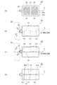
図1は、圧電モーター10を示す平面図、図2は、図1のD−D切断面を示す断面図である。図1、図2において、圧電モーター10は、矩形の平面を有し面内振動によって被駆動体を駆動する圧電素子20と、圧電素子20の第1主面20aの4隅方向に分離配置される支持部の各々に当接する第1支持部材30及び第2支持部材31を有する。なお、第1支持部材30及び第2支持部材31を第1主面支持部材とする。 FIG. 1 is a plan view showing the
また、圧電モーター10は、第1支持部材30を押圧する第1押え板40と、第2支持部材31を押圧する第2押え板41とからなる押え部材と、圧電素子20の第1主面20aと向かい合う第2主面20bと当接し、圧電素子20を挟んで、第1支持部材30に対して面対称となる位置に配設される第3支持部材32と、第2支持部材31の面対称となる位置に配設される第4支持部材33と、を有している。これら第3支持部材32と第4支持部材33を第2主面支持部材とする。これら第2主面支持部材を圧電素子20に押圧する機枠部材としてのケース70を、さらに有している。 In addition, the
そして、ケース70のケース底面71に、第2主面支持部材(第3支持部材32及び第4支持部材33)と、圧電素子20と、第1主面支持部材(第1支持部材30及び第2支持部材31)と、押え部材(第1押え板40及び第2押え板41)とを順に積み重ねて支持部の位置で押圧する弾性部材としての第1押えバネ60及び第2押えバネ61と、が備えられている。 Then, on the
第1押えバネ60は、第1押え板40と第1固定板50との間に挟持されており、固定ネジ80をケース70に締め付けることによって、第1支持部材30と第3支持部材32を圧電素子20に押圧する。
第2押えバネ61は、第2押え板41と第2固定板51との間に挟持されており、固定ネジ80をケース70に締め付けることによって、第2支持部材31と第4支持部材33を圧電素子20に押圧する。なお、図2では、第1押えバネ60及び第2押えバネ61が押圧していない初期状態を表している。The
The
この際、図2に示すように、第1固定板50及び第2固定板51と、ケース70との間には厚さ方向にギャップが存在する。これは、圧電素子20と第1主面支持部材と第2主面支持部材と第1押え板40及び第2押え板41とを積み重ねた場合に、これら構成要素の厚さのばらつきを第1押えバネ60と第2押えバネ61で吸収するためである。なお、本実施の形態では、第1押えバネ60と第2押えバネ61の押圧力はおよそ数kgである。 At this time, as shown in FIG. 2, there is a gap in the thickness direction between the
圧電素子20の短辺側の端部には、突起部28が設けられている。突起部28は、被駆動体と接触し、その摩擦力によって被駆動体を駆動させることから被駆動体との摩擦係数は高く、且つ耐摩耗性の優れた材料が用いられる。例えば、ジルコニア、セラミックス等の硬質材料が用いられる。突起部28は、圧電素子20の屈曲振動によって楕円運動し、被駆動体を駆動する。 A
続いて、本実施形態の圧電モーター10に用いられる圧電素子20、及び駆動方法について説明する。
図3は、圧電素子20の構成及び駆動方法を示す模式図であり、(a)は静止時の平面図、(b)及び(c)は圧電素子20の振動と、被駆動体の駆動方法を示し、(d)は、(b)と(c)の振動を合成して表す模式図である。Next, the
3A and 3B are schematic views showing the configuration and driving method of the
図3(a)において、圧電素子20には、圧電体21の第1主面20a側に第1励振電極22、第2励振電極23、第3励振電極24、第4励振電極25が形成されている。また、第1主面20aとは表裏の関係にある第2主面20b側に共通電極26(図2、参照)が、圧電体21の第2主面20b側のほぼ全面に形成されている。 In FIG. 3A, the
圧電体21の材料としては、圧電性を有する材料であれば特に限定されないが、PZT(チタン酸ジルコン酸鉛)が好適に用いられる。また、第1励振電極22、第2励振電極23、第3励振電極24、第4励振電極25及び共通電極26の材質としては、導電性金属であれば限定されないが、Agペーストをスクリーン印刷等で形成する方法や、Al,Au,W,Cu,Agなどをスパッタリング法や蒸着法などの方法で形成することができる。 The material of the
なお、第1励振電極22と第3励振電極24とは電気的に接続されており、第2励振電極23と第4励振電極25とは、電気的に接続されている。このような電極構成によれば、第1励振電極22と第3励振電極24とに電荷を印加すると圧電体21は伸長し(実線の矢印で示す)、電荷を除去すると復帰する縦振動が励起される。一方、第2励振電極23と第4励振電極25に電荷を印加すると圧電体21は伸長し(破線の矢印で示す)、電荷を除去すると復帰する縦振動が励起される。
このように、第1励振電極22と第3励振電極24、または第2励振電極23と第4励振電極25に電荷を印加することにより、圧電素子20は面内の屈曲振動が励振される。このように励起される屈曲振動について図3(b),(c),(d)を参照して説明する。The
In this way, by applying charges to the
図3(b)は、第1励振電極22及び第3励振電極24と共通電極26との間に電荷を印加し、第2励振電極23と第4励振電極25には電荷を印加しない場合を表しており、第1励振電極22及び第3励振電極24が形成されている範囲で縦振動が励起される(図3(a)、参照)。しかし、第2励振電極23と第4励振電極25には電荷が印加されていないため縦振動は励起されず、その結果、圧電素子20は、図3(b)のように面内において二次の屈曲振動を励起し、突起部28が図示する楕円軌道QLの矢印方向に楕円運動する。突起部28は被駆動体90に押圧されているため、突起部28のQL方向の楕円軌道によって、当接されている被駆動体90をHL方向に移動させる。
なお、図3(b)に示すように、屈曲振動の中心軸をLで表し、振動の節をP1,P2,P3で表し、振動モードをLaで表している。FIG. 3B shows a case where a charge is applied between the
As shown in FIG. 3B, the central axis of the bending vibration is represented by L, the vibration nodes are represented by P1, P2, and P3, and the vibration mode is represented by La.
突起部28と被駆動体90との接触部においては、突起部28の楕円軌道QLによって被駆動体90に対して接触部の摩擦力によって駆動力が生じる。この駆動力によって被駆動体90がHL方向に駆動される。In the contact portion between the
図3(c)は、第2励振電極23及び第4励振電極25と共通電極26との間に電荷を印加し、第1励振電極22及び第3励振電極24には電荷を印加しない場合を表しており、第2励振電極23と第4励振電極25とが形成されている範囲で縦振動が励起される(図3(a)、参照)。しかし、第1励振電極22及び第3励振電極24には電荷が印加されていないため縦振動は励起されず、その結果、圧電素子20は、図3(c)のように面内において二次の屈曲振動を励起し、突起部28が図示する楕円軌道QRの矢印方向に楕円運動する。突起部28は被駆動体90に押圧されているため、突起部28のQR方向の楕円運動によって、被駆動体90をHR方向に駆動させる。
なお、図3(c)に示すように、屈曲振動の中心軸をLで表し、振動の節をP1,P2,P3で表し、振動モードをLbで表している。FIG. 3C shows a case where charges are applied between the
As shown in FIG. 3C, the central axis of the bending vibration is represented by L, the vibration nodes are represented by P1, P2, and P3, and the vibration mode is represented by Lb.
突起部28と被駆動体90との接触部においては、突起部28の楕円軌道QRによって被駆動体90に対するして摩擦力によって駆動力が生じる。この駆動力によって被駆動体90がHR方向に駆動される。In the contact portion between the projecting
このように、第1励振電極22及び第3励振電極24と、第2励振電極23及び第4励振電極25への電荷の印加を切り換えることにより、圧電素子20の屈曲振動の方向を変え、被駆動体90の駆動方向を容易に切り換えることができる。
上述の圧電素子20の屈曲振動および縦振動の2つの振動モードにおける振動の節について図3(d)を用いて説明する。In this way, by switching the application of electric charges to the
The vibration nodes in the above-described two vibration modes of the bending vibration and the longitudinal vibration of the
図3(d)は、圧電素子20の振動モードを示す概念図である。図3(d)に示すように、圧電素子20は、図3(b)、図3(c)を用いて説明した振動状態の屈曲振動モードを表している。振動モードLa,Lbを合成して表すと、振動の中心軸L上に振動の節P1,P2,P3が存在する。 FIG. 3D is a conceptual diagram showing the vibration mode of the
この振動の節P1,P2,P3を通り圧電素子20の縦振動に直交する方向に延長した線Pr1,Pr2,Pr3(以降、節線Pr1,Pr2,Pr3と表す)上にかかる範囲は、圧電素子20の変位が他の位置より小さい領域である。従って、節線Pr1,Pr2,Pr3上にかかる範囲に圧電素子20を押圧支持する支持部を配置することが好ましく、圧電素子20の外形部に最も近い振動の節P2,P3を含む領域に支持部を配置することがなお好ましい。
続いて、圧電素子20の押圧支持構造について図4、図5を参照して説明する。The range of lines Pr1, Pr2, and Pr3 (hereinafter referred to as node lines Pr1, Pr2, and Pr3) extending in the direction orthogonal to the longitudinal vibration of the
Next, the pressing support structure of the
図4は、圧電素子20の支持部S1,S2,S3,S4と支持部材との関係を表す平面図である。ここで、第1支持部材30は、節線Pr2上に第1励振電極22と第2励振電極23とに跨るように配置されている。第1支持部材30と第1励振電極22とが交差する領域が支持部S1、第1支持部材30と第2励振電極23とが交差する領域が支持部S2である。第3支持部材32は、圧電素子20を挟んで第1支持部材30とほぼ面対称となるように配置されている(図5参照)。 FIG. 4 is a plan view showing the relationship between the support portions S1, S2, S3, and S4 of the
一方、第2支持部材31は、節線Pr3上に第3励振電極24と第4励振電極25とに跨るように配置されている。第2支持部材31と第3励振電極24とが交差する領域が支持部S3、第2支持部材31と第4励振電極25とが交差する領域が支持部S4である。第4支持部材33は、圧電素子20を挟んで第2支持部材31とほぼ面対称となるように配置されている(図5参照)。 On the other hand, the
以上説明したように、支持部S1,S2,S3,S4各々は、圧電素子20の4隅方向に配置されている。 As described above, each of the support portions S1, S2, S3, and S4 is disposed in the four corner directions of the
なお、本実施の形態の圧電素子20は、長さが30mm、幅が7.5mm、厚さが3.0mmの扁平な直方体であって、他のステップモーターやサーボモーターに比べて圧電モーター10の小型・軽量化を可能にする。 Note that the
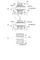
図5は、圧電素子20の押圧保持構造を模式的に表す断面図であり、図4のC−C切断面を表している。図5に示すように、圧電素子20は、ケース底面71上に第3支持部材32及び第4支持部材33を配設し、さらに、第3支持部材32及び第4支持部材33の上部に圧電素子20を重ね、圧電素子20の上部に第1支持部材30及び第2支持部材31を重ね、さらに第1押え板40及び第2押え板41を積み重ねて、支持部S1,S2,S3,S4の位置(図4参照)で第1押えバネ60と第2押えバネ61(図示は省略)によって押圧力Fで押圧支持されている。 FIG. 5 is a cross-sectional view schematically showing the pressing and holding structure of the
さらに具体的には図4、図5に示すように、第1支持部材30は、第1励振電極22の表面22aと第2励振電極23の表面23aに面接触し、第2支持部材31は、第3励振電極24の表面24aと第4励振電極25の表面25aに面接触する。また、第3支持部材32及び第4支持部材33は、共通電極26の表面26aに面接触する。なお、圧電素子20の押圧支持は、上記各要素の接触面には接合材が介在し、且つ凹凸を形成して摩擦力を大きくしておくことが望まれる。上記各要素の接触面の構成について図6、図7に実施形態を示し説明する。
(第1実施形態)More specifically, as shown in FIGS. 4 and 5, the
(First embodiment)
図6は、圧電モーターの第1実施形態を示す模式図であり、(a)は各要素を接合する前の状態を示し、(b)は各要素を接合した状態の一部を示す断面図である。本実施形態は、第1支持部材30と第2支持部材31と第3支持部材32と第4支持部材33の圧電素子20との接触面に凹凸Tを形成した構成を示している。また、(c)は凹凸Tの形状を例示している。なお、第1支持部材30、第2支持部材31、第3支持部材32、第4支持部材33は、ほぼ共通仕様であるため、第1支持部材30と、第1支持部材30に対向する第3支持部材32を例示して説明する。 6A and 6B are schematic views showing the first embodiment of the piezoelectric motor, in which FIG. 6A shows a state before joining the elements, and FIG. 6B is a cross-sectional view showing a part of the state where the elements are joined. It is. The present embodiment shows a configuration in which unevenness T is formed on the contact surfaces of the
図6(a)に示すように、第1支持部材30の圧電素子20に接触する側の表面30a、及び第3支持部材32の圧電素子20側の表面32aには凹凸Tが形成されている。本実施形態では、第1支持部材30、第2支持部材31、第3支持部材32、及び第4支持部材33の材質をポリイミドまたはABS樹脂等とし、各々の長さが5.0mm、幅が6.5mm、厚さが1.0mmの直方体とした。また、第1励振電極22、第2励振電極23、第3励振電極24、第4励振電極25、及び共通電極26をAgペーストとした。 As shown in FIG. 6A, unevenness T is formed on the
次に、励振電極22,23と第1支持部材30との間、及び共通電極26と第3支持部材32との間に接合材Sを塗布すると、接合材Sは第1支持部材30、第3支持部材32の凹凸Tの全面に回り込み、図6(b)に示すように接合される。なお、図6(b)では接合材Sは省略している。接合材Sの材料としては、例えばアクリル接着剤などが用いられる。このアクリル接着剤は、温度変化による強度劣化が少ないのが特徴である。 Next, when the bonding material S is applied between the
このように、接合材Sの接合力と第1支持部材30と第3支持部材32の凹凸Tがあることによって接触面の摩擦力を大きくすることができる。なお、凹凸Tも様々な形態を適用することができるので、代表的な実施形態を例示して説明する。
図6(c)は、凹凸Tを直線的に形成した例であって、上段に断面図、下段に平面図を表す。凹凸Tは、圧電素子20の縦振動方向に対してほぼ直交する方向に直線状に形成されている。この凹凸Tは、ヤスリやサンドペーパーや、硬質の転写型等を用いて形成される。凹凸Tのピッチや深さは、相手となる各電極の表面硬度によって決められる。As described above, the presence of the bonding force of the bonding material S and the unevenness T of the
FIG. 6C is an example in which the unevenness T is formed linearly, and a sectional view is shown in the upper stage and a plan view is shown in the lower stage. The unevenness T is linearly formed in a direction substantially orthogonal to the longitudinal vibration direction of the
以上述べたように、第1実施形態に係る圧電モーター10によれば、以下の効果を得ることができる。
前述した圧電モーター10は、第1支持部S1、第2支持部S2,第3支持部S3、第4支持部S4の各々の接合面に凹凸Tが形成されている。このことによって、経時的に接合面がずれることが少なく、圧電素子20の確実な保持と、被駆動体90の駆動エネルギー損失を防ぐことができる。
なお、凹凸は、各電極にも形成してもよく、第2実施形態として図7を参照して説明する。
(第2実施形態)As described above, according to the
In the
The unevenness may be formed on each electrode, and a second embodiment will be described with reference to FIG.
(Second Embodiment)
図7は、第2実施形態の一部を示す模式図であり、(a)は接合する前の状態を示し、(b)は凹凸形状の1例を示し、(c)は接合した状態を示す断面図である。本実施形態は、各支持部材と、圧電素子20に形成された第1励振電極22、第2励振電極23、第3励振電極24、及び第4励振電極25と、共通電極26に凹凸を形成した構成である。第1支持部材30及び第1励振電極22と、第3支持部材32と共通電極26を例示して説明する。なお、第1実施形態(図6、参照)と共通部分には同じ符号を付している。 FIG. 7 is a schematic diagram showing a part of the second embodiment, where (a) shows a state before joining, (b) shows an example of an uneven shape, and (c) shows a joined state. It is sectional drawing shown. In the present embodiment, irregularities are formed on each support member, the
図7(a)に示すように、第1支持部材30及び第3支持部材32には凹凸T、第1励振電極22及び共通電極26には凹凸T2が形成されている。 As shown in FIG. 7A, the
凹凸T2は、図7(b)に示すように、第1支持部材30と第1励振電極22との交差する領域、つまり支持部S1の領域に、第1励振電極22をパターニングすることで形成される。共通電極26も同様である。凹凸T2は、スクリーン印刷で容易に所望の形状に形成することが可能であって、凸部または凹部に相当する部分の幅及びピッチは、電極材料と支持部材の表面硬度によって決められる。 As shown in FIG. 7B, the unevenness T2 is formed by patterning the
そして、励振電極22,23と第1支持部材30との間、及び共通電極26と第3支持部材32との間に接合材Sを塗布すると、接合材Sは第1支持部材30、第3支持部材32の凹凸T、及び各電極の凹凸T2の全面に回り込み、図7(c)に示すように、接合される。なお、図7(c)では接合材Sは省略している。
このように、接合材Sの接合力と第1支持部材30と第3支持部材32の凹凸T、及び各電極の凹凸T2があることによって接触面の摩擦力を大きくすることができる。なお、励振電極側の凹凸T2と共通電極側の凹凸T2の形状は必ずしも同じでなくてもよい。When the bonding material S is applied between the
As described above, the bonding force of the bonding material S, the unevenness T of the
以上述べたように、第2実施形態に係る圧電モーター10によれば、以下の効果を得ることができる。
前述した圧電モーター10は、第1支持部S1、第2支持部S2,第3支持部S3、第4支持部S4の各々の接合面に凹凸Tが形成され、且つ第1励振電極22、第2励振電極23、第3励振電極24、及び第4励振電極25と、共通電極26に凹凸T2が形成されている。このことによって、摩擦力を更に高め、経時的に接合面がずれることが少なく、圧電素子20の確実な保持と、被駆動体90の駆動エネルギー損失を防ぐことができる。
(第3実施形態)As described above, according to the
In the
(Third embodiment)
上述した本実施例の圧電モーター10は、ロボットハンドを駆動する駆動部として好適に組み込むことができる。 The above-described
図8は、上記実施形態の圧電モーター10を組み込んだロボットハンド200を例示した説明図である。図示したロボットハンド200(ハンド部)は、基台202から複数本の指部203が立設されており、手首204を介してアーム210に接続されている。ここで、指部203の根元の部分は基台202内で移動可能となっており、この指部203の根元の部分に突起部28を押しつけた状態で圧電モーター10が搭載されている。このため、圧電モーター10を動作させることで、指部203を移動させて対象物を把持することができる。この圧電モーター10は、複数の指部203の間隔を変更する「駆動部」となっている。また、手首204の部分にも、手首204の端面に突起部28を押しつけた状態で圧電モーター10が搭載されている。このため、圧電モーター10を駆動させることで、基台202全体を回転させることが可能である。
(第4実施形態)FIG. 8 is an explanatory view illustrating a
(Fourth embodiment)
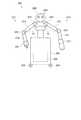
図9は、ロボットハンド200(ハンド部)を備えた単腕のロボット250を例示した説明図である。図示されるようにロボット250は、複数本のリンク部212(リンク部材)と、それらリンク部212の間を屈曲可能な状態で接続する関節部220とを備えたアーム210(腕部)を有している。また、ロボットハンド200はアーム210の先端に接続されている。そして、関節部220には、関節部220を屈曲させるための駆動部として圧電モーター10が内蔵されている。このため、圧電モーター10を動作させることにより、それぞれの関節部220を任意の角度だけ屈曲させることが可能である。
(第5実施形態)FIG. 9 is an explanatory diagram illustrating a single-
(Fifth embodiment)
図10は、ロボットハンド200を備えた複腕のロボット260を例示した説明図である。図示されるようにロボット250は、複数本のリンク部212と、それらリンク部212の間を屈曲可能な状態で接続する関節部220とを備えたアーム210を複数本(図示した例では2本)有している。アーム210の先端には、ロボットハンド200や、工具201(ハンド部)が接続されている。また、頭部262には複数台のカメラ263が搭載され、本体部264の内部には全体の動作を制御する制御部266が搭載されている。更に、本体部264の底面に設けられたキャスター268によって搬送可能である。このロボット260にも、関節部220には、関節部220を屈曲させるための駆動部として圧電モーター10が内蔵されている。このため、圧電モーター10を駆動させることにより、それぞれの関節部220を任意の角度だけ屈曲させることが可能である。 FIG. 10 is an explanatory diagram illustrating a
10…圧電モーター、20…圧電素子、20a…第1主面、20b…第2主面、22…第1励振電極、23…第2励振電極、24…第3励振電極、25…第4励振電極、26…共通電極、30…第1支持部材、30a…表面、31…第2支持部材、32…第3支持部材、32a…表面、33…第4支持部材、70…ケース、200…ロボットハンド、250…ロボット、260…ロボット。 DESCRIPTION OF
Claims (4)
Translated fromJapanese前記圧電素子の前記第1主面の4隅方向に分離配置される支持部に面接触する第1主面支持部材と、
前記第1主面支持部材の前記第1主面と向かい合う面に面接触する押え部材と、
前記圧電素子を挟んで前記第1主面支持部材に対して面対称となる位置に配置され、前記圧電素子の前記第2主面に面接触する第2主面支持部材と、
前記第2主面支持部材の前記圧電素子との接触面に対して反対側の面に面接触する機枠部材と、を備え、
前記機枠部材と前記第2主面支持部材と前記圧電素子と前記第1主面支持部材と前記押え部材とが順に積み重ねられ、前記圧電素子と第1主面支持部材との接触面、前記圧電素子と第2主面支持部材との接触面は接合材で接合され、前記第1主面支持部材、及び前記第2主面支持部材の前記接触面に凹凸が形成されていることを特徴とする圧電モーター。A piezoelectric element having a first main surface and a second main surface that vibrate when the bending vibration mode is excited or vibrated by the bending vibration mode and the longitudinal vibration mode;
A first main surface support member that is in surface contact with support portions that are separately disposed in the four corner directions of the first main surface of the piezoelectric element;
A pressing member that is in surface contact with a surface of the first main surface support member that faces the first main surface;
A second main surface support member disposed in a plane-symmetrical position with respect to the first main surface support member with the piezoelectric element interposed therebetween, and in surface contact with the second main surface of the piezoelectric element;
A machine frame member that is in surface contact with the surface opposite to the contact surface with the piezoelectric element of the second main surface support member,
The machine frame member, the second main surface support member, the piezoelectric element, the first main surface support member, and the pressing member are sequentially stacked, and a contact surface between the piezoelectric element and the first main surface support member, A contact surface between the piezoelectric element and the second main surface support member is bonded with a bonding material, and irregularities are formed on the contact surfaces of the first main surface support member and the second main surface support member. A piezoelectric motor.
前記複数本の指部が移動可能に立設された基台と、
前記基台に設けられて前記指部の基端を駆動することによって、前記複数本の指部の間隔を変更する駆動部と、を有し、
前記駆動部は、
屈曲振動モードが励振されて振動し、または前記屈曲振動モードと縦振動モードとが励振されて振動する圧電素子と、
前記圧電素子の第1主面の4隅方向に分離配置される支持部に面接触する第1主面支持部材と、
前記第1主面支持部材の前記第1主面と向かい合う面に面接触する押え部材と、
前記圧電素子を挟んで前記第1主面支持部材に対して面対称となる位置に配置され、前記圧電素子に面接触する第2主面支持部材と、
前記第2主面支持部材の前記圧電素子との接触面に対して反対側の面に面接触する機枠部材と、を備え、
前記機枠部材と前記第2主面支持部材と前記圧電素子と前記第1主面支持部材と前記押え部材とが順に積み重ねられ、前記圧電素子と第1主面支持部材との接触面、前記圧電素子と第2主面支持部材との接触面は接合材で接合され、前記第1主面支持部材、及び前記第2主面支持部材の前記接触面に凹凸が形成されていることを特徴とするロボットハンド。A robot hand that grips an object using a plurality of fingers,
A base on which the plurality of fingers are vertically movable;
A drive unit that is provided on the base and drives a base end of the finger unit to change an interval between the plurality of finger units;
The drive unit is
A piezoelectric element that vibrates when the flexural vibration mode is excited, or vibrates when the flexural vibration mode and the longitudinal vibration mode are excited;
A first main surface support member that is in surface contact with support portions that are separately disposed in the four corner directions of the first main surface of the piezoelectric element;
A pressing member that is in surface contact with a surface of the first main surface support member that faces the first main surface;
A second main surface support member disposed in a plane-symmetrical position with respect to the first main surface support member across the piezoelectric element, and in surface contact with the piezoelectric element;
A machine frame member that is in surface contact with the surface opposite to the contact surface with the piezoelectric element of the second main surface support member,
The machine frame member, the second main surface support member, the piezoelectric element, the first main surface support member, and the pressing member are sequentially stacked, and a contact surface between the piezoelectric element and the first main surface support member, A contact surface between the piezoelectric element and the second main surface support member is bonded with a bonding material, and irregularities are formed on the contact surfaces of the first main surface support member and the second main surface support member. A robot hand.
前記腕部に設けられたハンド部と、
を備えたロボットであって、
前記関節部に設けられて前記関節部を屈曲あるいは回転駆動させる駆動部を有しており、
前記駆動部は、
屈曲振動モードが励振されて振動し、または前記屈曲振動モードと縦振動モードとが励振されて振動する圧電素子と、
前記圧電素子の第1主面の4隅方向に分離配置される支持部に面接触する第1主面支持部材と、
前記第1主面支持部材の前記第1主面と向かい合う面に面接触する押え部材と、
前記圧電素子を挟んで前記第1主面支持部材に対して面対称となる位置に配置され、前記圧電素子に面接触する第2主面支持部材と、
前記第2主面支持部材の前記圧電素子との接触面に対して反対側の面に面接触する機枠部材と、を備え、
前記機枠部材と前記第2主面支持部材と前記圧電素子と前記第1主面支持部材と前記押え部材とが順に積み重ねられ、前記圧電素子と第1主面支持部材との接触面、前記圧電素子と第2主面支持部材との接触面は接合材で接合され、前記第1主面支持部材、及び前記第2主面支持部材の前記接触面に凹凸が形成されていることを特徴とするロボット。An arm provided with a rotatable joint, and
A hand portion provided on the arm portion;
A robot equipped with
It has a drive part that is provided at the joint part and that drives the joint part to bend or rotate,
The drive unit is
A piezoelectric element that vibrates when the flexural vibration mode is excited, or vibrates when the flexural vibration mode and the longitudinal vibration mode are excited;
A first main surface support member that is in surface contact with support portions that are separately disposed in the four corner directions of the first main surface of the piezoelectric element;
A pressing member that is in surface contact with a surface of the first main surface support member that faces the first main surface;
A second main surface support member disposed in a plane-symmetrical position with respect to the first main surface support member across the piezoelectric element, and in surface contact with the piezoelectric element;
A machine frame member that is in surface contact with the surface opposite to the contact surface with the piezoelectric element of the second main surface support member,
The machine frame member, the second main surface support member, the piezoelectric element, the first main surface support member, and the pressing member are sequentially stacked, and a contact surface between the piezoelectric element and the first main surface support member, A contact surface between the piezoelectric element and the second main surface support member is bonded with a bonding material, and irregularities are formed on the contact surfaces of the first main surface support member and the second main surface support member. Robot.
Priority Applications (4)
| Application Number | Priority Date | Filing Date | Title |
|---|---|---|---|
| JP2012076462AJP5857843B2 (en) | 2012-03-29 | 2012-03-29 | Piezoelectric motor, robot hand and robot |
| CN2013101023896ACN103368455A (en) | 2012-03-29 | 2013-03-27 | Piezoelectric motor, robot hand, and robot |
| US13/852,297US20130255427A1 (en) | 2012-03-29 | 2013-03-28 | Piezoelectric motor, robot hand, and robot |
| EP13161653.4AEP2645560A1 (en) | 2012-03-29 | 2013-03-28 | Piezoelectric motor |
Applications Claiming Priority (1)
| Application Number | Priority Date | Filing Date | Title |
|---|---|---|---|
| JP2012076462AJP5857843B2 (en) | 2012-03-29 | 2012-03-29 | Piezoelectric motor, robot hand and robot |
Publications (2)
| Publication Number | Publication Date |
|---|---|
| JP2013207978A JP2013207978A (en) | 2013-10-07 |
| JP5857843B2true JP5857843B2 (en) | 2016-02-10 |
Family
ID=47997241
Family Applications (1)
| Application Number | Title | Priority Date | Filing Date |
|---|---|---|---|
| JP2012076462AExpired - Fee RelatedJP5857843B2 (en) | 2012-03-29 | 2012-03-29 | Piezoelectric motor, robot hand and robot |
Country Status (4)
| Country | Link |
|---|---|
| US (1) | US20130255427A1 (en) |
| EP (1) | EP2645560A1 (en) |
| JP (1) | JP5857843B2 (en) |
| CN (1) | CN103368455A (en) |
Families Citing this family (10)
| Publication number | Priority date | Publication date | Assignee | Title |
|---|---|---|---|---|
| JP6467809B2 (en)* | 2014-08-13 | 2019-02-13 | セイコーエプソン株式会社 | Piezoelectric driving device and driving method thereof, robot and driving method thereof |
| CN105538288B (en)* | 2014-10-22 | 2020-08-28 | 精工爱普生株式会社 | robot |
| JP6543951B2 (en)* | 2015-02-18 | 2019-07-17 | セイコーエプソン株式会社 | Piezoelectric drive device, robot, and method of driving them |
| JP2017017916A (en)* | 2015-07-03 | 2017-01-19 | セイコーエプソン株式会社 | Piezoelectric drive device, robot, and drive method of piezoelectric drive device |
| JP6592993B2 (en) | 2015-07-07 | 2019-10-23 | セイコーエプソン株式会社 | Piezoelectric drive device and robot |
| JP6834262B2 (en) | 2016-08-31 | 2021-02-24 | セイコーエプソン株式会社 | Manufacturing method of oscillator, piezoelectric actuator, piezoelectric motor, robot, electronic component transfer device and oscillator |
| JP6919275B2 (en)* | 2017-03-31 | 2021-08-18 | セイコーエプソン株式会社 | Piezoelectric drive devices, piezoelectric motors, robots, electronic component transfer devices and printers |
| JP7167522B2 (en)* | 2018-07-27 | 2022-11-09 | セイコーエプソン株式会社 | robot arm |
| US11381145B2 (en)* | 2020-03-02 | 2022-07-05 | David Hirshberg | Step motor |
| CN116252318B (en)* | 2022-12-08 | 2023-09-12 | 浙江大学 | Low-temperature nano manipulator and control method |
Family Cites Families (13)
| Publication number | Priority date | Publication date | Assignee | Title |
|---|---|---|---|---|
| JPS58164600A (en)* | 1982-03-09 | 1983-09-29 | Microbial Chem Res Found | 3"-deoxystreptomycin |
| AT384912B (en)* | 1982-04-16 | 1988-01-25 | Ki Polt I | PIEZOELECTRIC MOTOR |
| JPH04145879A (en)* | 1990-10-02 | 1992-05-19 | Omron Corp | Ultrasonic motor |
| EP0513288A1 (en)* | 1990-12-04 | 1992-11-19 | Scansov Transport Ab | Piezoelectric motor |
| EP0633616B1 (en)* | 1993-07-09 | 2002-01-30 | Nanomotion Ltd | Ceramic motor |
| IL114656A0 (en)* | 1995-07-18 | 1995-11-27 | Nanomotion Ltd | Ceramic motor |
| JP2980541B2 (en) | 1994-06-28 | 1999-11-22 | ナノモーション・リミテッド | Micro motor |
| JP4376342B2 (en)* | 1999-03-02 | 2009-12-02 | セイコーインスツル株式会社 | Electronic clock |
| JP4137601B2 (en)* | 2002-11-12 | 2008-08-20 | シャープ株式会社 | Robot hand control method, robot hand |
| JP2004260990A (en)* | 2003-02-06 | 2004-09-16 | Seiko Epson Corp | Drives and operating devices |
| JP4060839B2 (en)* | 2004-09-29 | 2008-03-12 | 株式会社豊電子工業 | Hand device for work robot |
| JP4394158B2 (en)* | 2009-02-27 | 2010-01-06 | セイコーインスツル株式会社 | Ultrasonic motor and electronic device with ultrasonic motor |
| JP2010233337A (en)* | 2009-03-26 | 2010-10-14 | Seiko Epson Corp | Piezoelectric motor, liquid ejecting apparatus and clock |
- 2012
- 2012-03-29JPJP2012076462Apatent/JP5857843B2/ennot_activeExpired - Fee Related
- 2013
- 2013-03-27CNCN2013101023896Apatent/CN103368455A/enactivePending
- 2013-03-28EPEP13161653.4Apatent/EP2645560A1/ennot_activeWithdrawn
- 2013-03-28USUS13/852,297patent/US20130255427A1/ennot_activeAbandoned
Also Published As
| Publication number | Publication date |
|---|---|
| US20130255427A1 (en) | 2013-10-03 |
| JP2013207978A (en) | 2013-10-07 |
| CN103368455A (en) | 2013-10-23 |
| EP2645560A1 (en) | 2013-10-02 |
Similar Documents
| Publication | Publication Date | Title |
|---|---|---|
| JP5857843B2 (en) | Piezoelectric motor, robot hand and robot | |
| JP4069161B2 (en) | Piezoelectric element and ultrasonic actuator | |
| JP4628363B2 (en) | Electromechanical drive unit that resonates flat | |
| CN102067435B (en) | Vibration actuator | |
| JP4069160B2 (en) | Ultrasonic actuator | |
| CN101160710B (en) | Ultrasonic actuator | |
| JP5953724B2 (en) | Piezoelectric motor, drive device, robot, electronic component transport device, electronic component inspection device, printer | |
| US8633632B2 (en) | Vibration actuator and method for manufacturing the same | |
| JP2014018027A (en) | Vibration type actuator, imaging apparatus, and stage | |
| EP3089348B1 (en) | Piezoelectric motor | |
| JP4452275B2 (en) | Piezoelectric mechanical drive | |
| JPWO2002015378A1 (en) | Folding type piezoelectric stator, folding type piezoelectric actuator and their applications | |
| JPH10243668A (en) | Vibration actuator | |
| JP2012210053A (en) | Piezoelectric actuator, robot, and robot hand | |
| US20150349665A1 (en) | Piezoelectric actuator and robot | |
| JP5776269B2 (en) | Piezoelectric actuator, robot and robot hand | |
| JP2007312600A (en) | Piezoelectric element and ultrasonic actuator | |
| JP2008178209A (en) | Ultrasonic actuator | |
| JP2007300798A (en) | Piezoelectric element and ultrasonic actuator | |
| JP5144097B2 (en) | Ultrasonic motor device | |
| JP2017221042A (en) | Piezoelectric element | |
| JP2022112669A (en) | Piezo drives and robots | |
| JP2022165014A (en) | Piezoelectric driving device and robot | |
| JP2024086055A (en) | Piezoelectric drive device and robot system | |
| JP2021191049A (en) | Piezoelectric drives, piezoelectric motors and robots |
Legal Events
| Date | Code | Title | Description |
|---|---|---|---|
| A621 | Written request for application examination | Free format text:JAPANESE INTERMEDIATE CODE: A621 Effective date:20141119 | |
| RD04 | Notification of resignation of power of attorney | Free format text:JAPANESE INTERMEDIATE CODE: A7424 Effective date:20150107 | |
| A977 | Report on retrieval | Free format text:JAPANESE INTERMEDIATE CODE: A971007 Effective date:20151021 | |
| TRDD | Decision of grant or rejection written | ||
| A01 | Written decision to grant a patent or to grant a registration (utility model) | Free format text:JAPANESE INTERMEDIATE CODE: A01 Effective date:20151117 | |
| A61 | First payment of annual fees (during grant procedure) | Free format text:JAPANESE INTERMEDIATE CODE: A61 Effective date:20151130 | |
| R150 | Certificate of patent or registration of utility model | Ref document number:5857843 Country of ref document:JP Free format text:JAPANESE INTERMEDIATE CODE: R150 | |
| S531 | Written request for registration of change of domicile | Free format text:JAPANESE INTERMEDIATE CODE: R313531 | |
| R350 | Written notification of registration of transfer | Free format text:JAPANESE INTERMEDIATE CODE: R350 | |
| LAPS | Cancellation because of no payment of annual fees |