JP5853566B2 - Automobile steering column cover structure and automobile equipped with the steering column cover structure - Google Patents
Automobile steering column cover structure and automobile equipped with the steering column cover structureDownload PDFInfo
- Publication number
- JP5853566B2 JP5853566B2JP2011223624AJP2011223624AJP5853566B2JP 5853566 B2JP5853566 B2JP 5853566B2JP 2011223624 AJP2011223624 AJP 2011223624AJP 2011223624 AJP2011223624 AJP 2011223624AJP 5853566 B2JP5853566 B2JP 5853566B2
- Authority
- JP
- Japan
- Prior art keywords
- column cover
- steering column
- accelerator pedal
- vehicle
- pedal
- Prior art date
- Legal status (The legal status is an assumption and is not a legal conclusion. Google has not performed a legal analysis and makes no representation as to the accuracy of the status listed.)
- Expired - Fee Related
Links
Images


Classifications
- B—PERFORMING OPERATIONS; TRANSPORTING
- B60—VEHICLES IN GENERAL
- B60R—VEHICLES, VEHICLE FITTINGS, OR VEHICLE PARTS, NOT OTHERWISE PROVIDED FOR
- B60R21/00—Arrangements or fittings on vehicles for protecting or preventing injuries to occupants or pedestrians in case of accidents or other traffic risks
- B60R21/02—Occupant safety arrangements or fittings, e.g. crash pads
- B60R21/04—Padded linings for the vehicle interior ; Energy absorbing structures associated with padded or non-padded linings
- B60R21/05—Padded linings for the vehicle interior ; Energy absorbing structures associated with padded or non-padded linings associated with the steering wheel, steering hand lever or steering column
- B—PERFORMING OPERATIONS; TRANSPORTING
- B60—VEHICLES IN GENERAL
- B60K—ARRANGEMENT OR MOUNTING OF PROPULSION UNITS OR OF TRANSMISSIONS IN VEHICLES; ARRANGEMENT OR MOUNTING OF PLURAL DIVERSE PRIME-MOVERS IN VEHICLES; AUXILIARY DRIVES FOR VEHICLES; INSTRUMENTATION OR DASHBOARDS FOR VEHICLES; ARRANGEMENTS IN CONNECTION WITH COOLING, AIR INTAKE, GAS EXHAUST OR FUEL SUPPLY OF PROPULSION UNITS IN VEHICLES
- B60K26/00—Arrangement or mounting of propulsion-unit control devices in vehicles
- B60K26/02—Arrangement or mounting of propulsion-unit control devices in vehicles of initiating means or elements
- B—PERFORMING OPERATIONS; TRANSPORTING
- B60—VEHICLES IN GENERAL
- B60R—VEHICLES, VEHICLE FITTINGS, OR VEHICLE PARTS, NOT OTHERWISE PROVIDED FOR
- B60R13/00—Elements for body-finishing, identifying, or decorating; Arrangements or adaptations for advertising purposes
- B60R13/02—Internal Trim mouldings ; Internal Ledges; Wall liners for passenger compartments; Roof liners
- G—PHYSICS
- G05—CONTROLLING; REGULATING
- G05G—CONTROL DEVICES OR SYSTEMS INSOFAR AS CHARACTERISED BY MECHANICAL FEATURES ONLY
- G05G1/00—Controlling members, e.g. knobs or handles; Assemblies or arrangements thereof; Indicating position of controlling members
- G05G1/30—Controlling members actuated by foot
Landscapes
- Engineering & Computer Science (AREA)
- Mechanical Engineering (AREA)
- Chemical & Material Sciences (AREA)
- Combustion & Propulsion (AREA)
- Transportation (AREA)
- Physics & Mathematics (AREA)
- General Physics & Mathematics (AREA)
- Automation & Control Theory (AREA)
- Body Structure For Vehicles (AREA)
- Steering Controls (AREA)
- Mechanical Control Devices (AREA)
Description
Translated fromJapaneseこの発明は、自動車のステアリングコラムを覆うステアリングコラムカバー構造およびそのステアリングコラムカバー構造を備えた自動車に関する。The present invention relates to a steering column cover structure that covers a steering column ofan automobile and an automobile equipped with the steering column cover structure .
自動車のペダル装置のうち、アクセルペダルは、一時に大きな力で踏み込み操作をするクラッチペダルやブレーキペダルとは異なり、ペダル(踏み込み面)の角度を定常的に保持するように操作することによって、所望の車速を実現するものであることから、他のペダルに比べてその踏み込み力は必然的に小さくなる。このため、従来、車両前突時には、以下に述べるような問題があった。 Among the pedal devices of automobiles, the accelerator pedal is different from the clutch pedal and the brake pedal that are depressed with a large force at a time, and is desired by operating the pedal (depressed surface) to maintain a constant angle. Therefore, the stepping force is inevitably smaller than that of other pedals. For this reason, conventionally, there have been problems as described below at the time of a vehicle front collision.
具体的には、図9に示すように、自動車Vが斜め衝突またはオフセット衝突等の衝突形態で障害物αに前突した時、車体は、図中二点鎖線で示すように、障害物αを中心にして旋回するように移動する一方、車室内の乗員Mは、慣性によって車両走行時(前突前)の走行方向に移動しようとする。この時、乗員Mは車体に対して斜めに相対移動することになるため、上述したように比較的小さい踏み込み力でアクセルペダル104を踏み込んでいる足Mfが、前突時の衝突加速度の作用により、アクセルペダル104の踏み込み面から滑って相対的に車幅方向に移動する虞があった。 Specifically, as shown in FIG. 9, when the vehicle V collides with the obstacle α in a collision mode such as an oblique collision or an offset collision, the vehicle body is obstructed by the obstacle α as shown by a two-dot chain line in the figure. The vehicle occupant M tries to move in the travel direction during vehicle travel (before the front collision) due to inertia. At this time, since the occupant M moves obliquely relative to the vehicle body, the foot Mf that depresses the
このように、足Mfがアクセルペダル104から移動すると、足Mfがアクセルペダル104よりも衝撃吸収機能の低い部位に移動して最適な衝撃吸収ができなかったり、足Mfの姿勢が不自然になって、足Mfに負荷がかかったりする等して、想定外の問題が発生する懸念があるため、好ましくない。 As described above, when the foot Mf moves from the
また、従来、自動車のペダル装置として、踏み込み面の踏み込み操作により平行移動、または前傾する所謂オルガン式ペダルが知られている。このオルガン式ペダルは、乗員の踏み込み操作によって踏み込み面が前方、かつ、下方に移動するものであり、踵を動かさなくても踏み込み面の踏み込み点が変化し難いという特徴がある。このため、オルガン式ペダルは、踏み込み操作によって踏み込み面が前方、かつ、上方に移動し、フロア面に対して直交する方向に傾斜する所謂吊り下げ式ペダルに対し、踵を基準にして踏み込み面を調整したり、保持したりし易いという利点がある。 Conventionally, a so-called organ-type pedal that is translated or tilted forward by a stepping operation on a stepping surface is known as a pedal device for an automobile. This organ-type pedal is characterized in that the stepping surface moves forward and downward by the occupant's stepping operation, and the stepping point of the stepping surface is difficult to change without moving the heel. For this reason, the organ-type pedal has a stepping surface with respect to a saddle as opposed to a so-called suspension type pedal, in which the stepping surface moves forward and upward by a stepping operation and tilts in a direction perpendicular to the floor surface. There is an advantage that it is easy to adjust and hold.
しかしながら、このオルガン式のペダルにおいても、以下に述べる理由により、上述したアクセルペダル104と同様の問題があった。 However, this organ-type pedal has the same problem as the
具体的には、オルガン式ペダルは、吊り下げ式ペダルと異なり、踏み込む程、踏み込み面が水平に近づくため、足が踏ん張り難い状態となる。このため、図9に示すように、自動車Vが障害物αに前突した時には、アクセルペダル104の場合と同様、オルガン式ペダルを踏み込んでいる足が、踏み込み面から滑って相対的に車幅方向に移動する虞があった。 Specifically, the organ-type pedal is different from the suspension-type pedal, and the more the pedal is depressed, the more the stepping surface approaches to the horizontal, so that it is difficult for the foot to be stepped on. For this reason, as shown in FIG. 9, when the vehicle V collides with the obstacle α, as in the case of the
ところで、従来、車両前突時に乗員の膝や胸部に加わる衝撃を、ステアリングコラムを覆うステアリングコラムカバーで吸収するように構成したものが知られている(下記特許文献1参照)。 By the way, there is conventionally known a configuration in which an impact applied to an occupant's knee or chest during a vehicle front-end collision is absorbed by a steering column cover that covers the steering column (see
また、従来、車両の斜突時に乗員が車体に対して斜めに相対移動することを、乗員の膝に向かって膨張展開するニーエアバッグによって抑制するように構成したものも知られている(下記特許文献2参照)。 Conventionally, there is also known a configuration in which a knee airbag that inflates and deploys toward an occupant's knee is restrained from causing the occupant to move obliquely relative to the vehicle body when the vehicle leans (see below). Patent Document 2).
しかしながら、前記特許文献1、2の何れも、ペダルを踏み込んでいる足が車両前突時にペダルの踏み込み面から滑って移動するという問題について何ら開示されておらず、これらの従来技術では、上述した足の移動を確実に抑制することができなかった。 However, none of
この発明は、乗員の乗降性を確保しつつ、車両前突時に足がペダルから車幅方向に移動することを抑制できる自動車のステアリングコラムカバー構造およびそのステアリングコラムカバー構造を備えた自動車を提供することを目的とする。The present invention provides asteering column cover structure for an automobile anda vehicle equipped with the steering column cover structure that can prevent the foot from moving in the vehicle width direction from the pedal in the event of a frontal collision while ensuring passenger occupancy. For the purpose.
この発明による自動車のステアリングコラムカバー構造は、ステアリングコラムを覆うステアリングコラムカバーを設け、上記ステアリングコラムカバーの下面のうち、前側かつアクセルペダル側の部分に、下方に突出する突出部が形成されており、上記ステアリングコラムカバーにおけるアクセルペダルがない側の側面と下面とが成す角部を、ステアリングシャフトを通る中心線を対称線として、アクセルペダル側に仮想的に配置したときに、その角部がステアリングコラムカバーの外側に存在するように、上記ステアリングコラムカバーの下面の上記突出部とアクセルペダル側の側面とに面取り状に斜面が形成されていて、該斜面が膝のガイド面として機能するものである。The steering column cover structure for an automobile according to the present inventionis provided with a steering column cover that covers the steering column, and a protruding portion that protrudes downward is formed on the front side and the accelerator pedal side portion of the lower surface of the steering column cover. When the corner formed by the side surface and the lower surface on the side without the accelerator pedal in the steering column cover is virtually arranged on the accelerator pedal side with the center line passing through the steering shaft as a symmetry line, the corner portion is the steering wheel. A slope is formed in a chamfered shape on the protruding portion on the lower surface of the steering column cover and the side surface on the accelerator pedal side so as to exist on the outside of the column cover, and the slope functions as a knee guide surface. is there.
この構成によれば、車両前突時に足が滑り易いアクセルペダル側の脚部が、アクセルペダルから相対的に車幅方向に移動することを上記斜面によって抑制でき、その結果、足がアクセルペダルから車幅方向に移動することを抑制できる。According to this configuration, it is possible to suppress the movement of the leg portion on the accelerator pedal side, in which the foot easily slips at the time of a vehicle frontal collision, in the vehicle width direction relative to the accelerator pedal by theslope , and as a result, the foot is separated from the accelerator pedal. Movement in the vehicle width direction can be suppressed.
さらに、車両前側に設けた斜面よりも高い位置にステアリングコラムカバーの下面後端部を設定しているため、膝が比較的上方に位置する行動形態(降車モード)で乗員が降車したとしても、膝とステアリングコラムカバーとの干渉を回避することができ、その結果、乗降性を確保することができる。Furthermore, since the setting the lower surface rear end portion of the steering column cover at a position higher thanthe slope provided on the vehicle frontside, even the passenger gets off behavioral form the knee is positioned relatively upward (getting-off mode) Thus, it is possible to avoid the interference between the knee and the steering column cover, and as a result, it is possible to ensure boarding / exiting performance.
また、前記斜面が、前記ステアリングコラムカバーの、前記ステアリングシャフト軸方向における後端部よりも前側で、前記下面後端部よりも前側の位置から、前記ステアリングコラムカバーの前記アクセルペダル側の側部まで側方、かつ上方に向かって面取り状に形成されるものであり、この構成により、下方に突出する部位(突出部)よりも車両後方の位置で可及的早期に脚部をガイドすることができるため、脚部がペダルから相対的に車幅方向に移動することをより円滑に抑制できる。Further, theslope, the steering column cover, in frontside of the rear end of the steering shaft axial direction, from the lower surface rear end position of the frontside of, the accelerator pedal side of the steering column cover side to side, and is intended to beformed in a chamfered shape upward, by this arrangement, the as much as possible early leg at the position of the vehicle rear than site(protrusion) that protrudesbelow side Since it can guide, it can control more smoothly that a leg part moves to a vehicle width direction relatively from a pedal.
さらに、前記斜面は、ステアリングコラムカバーの下面の上記突出部とアクセルペダル側の側面とに面取り状に形成されており、この構成により、アクセルペダル側の脚部を車幅方向にガイドする範囲を拡大することができる。これにより、車両前突時、乗員の膝が車幅方向にぶれたとしても脚部を安定的にガイドすることができる。Further, theinclinedsurface is formed in a chamfered shape on the protruding portion on the lower surface of the steering column cover and the side surface on the accelerator pedal side, and this configuration provides a range for guiding the leg portion on the accelerator pedal side in the vehicle width direction. Can be enlarged. Thereby, even if a passenger | crew's knee shakes at the vehicle width direction at the time of vehicle front collision, a leg part can be guided stably.
そして、アクセルペダル側のみに上記斜面を形成して、アクセルペダルが配設されていない反対側のステアリングコラムカバー内部では、各種補機を収納するためのスペースを確保することができる。And thesaid slope is formed only in the accelerator pedal side, and the space for accommodating various accessories can be ensured inside the steering column cover on the opposite side wherethe accelerator pedal is not disposed.
この発明の一実施態様においては、前記ステアリングコラムカバーの下面の、前記ペダル側と反対側の部位に、ステアリング位置調整レバーが設けられているものである。 In one embodiment of the present invention, a steering position adjusting lever is provided on a portion of the lower surface of the steering column cover opposite to the pedal side.
この構成によれば、斜面のガイド機能を確保しつつ、乗員着座時に脚部の周辺がステアリング位置調整レバーの存在によって窮屈になることを抑制できる。According to this structure, it can suppress that the periphery of a leg part becomes cramped by presence of a steering position adjustment lever at the time of passenger | crew sitting, ensuring the guide function of aslope .
この発明の一実施態様においては、前記アクセルペダルは、揺動中心が踏み込み面の上下中心、または下方に設定されたペダルとしたものである。 In one embodiment of the present invention, the accelerator pedal is a pedal whose swing center is set at the vertical center of the stepping surface or below.
この構成によれば、揺動中心が踏み込み面の上下中心、または下方に設定されることによって車両前突時に足が滑り易いアクセルペダル側の脚部が、アクセルペダルから相対的に車幅方向に移動することをガイド面によって抑制でき、その結果、足がアクセルペダルから車幅方向に移動することを抑制できる。 According to this configuration, the leg portion on the accelerator pedal side, in which the foot is easy to slip when the vehicle collides, is set in the vehicle width direction relative to the accelerator pedal by setting the swing center at the vertical center of the stepping surface or below. The movement can be suppressed by the guide surface, and as a result, the movement of the foot from the accelerator pedal in the vehicle width direction can be suppressed.
この発明によれば、車両前突時に足が滑り易いアクセルペダル側の脚部が、アクセルペダルから相対的に車幅方向に移動することを斜面によって抑制でき、その結果、足がアクセルペダルから車幅方向に移動することを抑制できる。According to the present invention, it is possible to suppress the movement of the leg portion on the accelerator pedal side, in which the foot easily slips at the time of a vehicle collision, in the vehicle width direction relative to the accelerator pedal by theslope , and as a result, the foot is moved from the accelerator pedal to the vehicle. Movement in the width direction can be suppressed.
さらに、車両前方に設けた斜面よりも高い位置にステアリングコラムカバーの下面後端部を設定されるため、膝が比較的上方に位置する行動形態(降車モード)で乗員が降車したとしても、膝とステアリングコラムカバーとの干渉を回避することができ、その結果、乗降性を確保することができる。Furthermore, even becauseset the lower surface rear end portion of the steering column cover at a position higher thanthe slope provided on the vehicle front, the occupant behavioral form the knee is positioned relatively upward (getting-off mode) gets off the knee And the steering column cover can be avoided, and as a result, boarding / exiting performance can be ensured.
以下、図面に基づいて本発明の実施形態を詳述する。
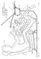
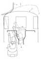
図1は、本発明の実施形態に係るステアリングコラムカバー構造を備えた車両前部を示す側面図であり、図2は、同平面図である。図1、図2に示す自動車Vには、その車室内左側に運転席シート1が配設されると共に、そのシートクッション1aをスライド変位させてその前後位置を調整する前後位置調整機構2が設けられている。そして、この前後位置調整機構2は、図1に示すように、車両前方かつ上方に傾斜するように設けられている。なお、図中において、矢印(F)は車両前方、矢印(R)は車両後方を示す。Hereinafter, embodiments of the present invention will be described in detail with reference to the drawings.
FIG. 1 is a side view showing a vehicle front portion provided with a steering column cover structure according to an embodiment of the present invention, and FIG. 2 is a plan view thereof. 1 and 2 is provided with a driver's
また、前記車室の前部左側には、車幅方向に延びる樹脂性のインストルメントパネル3が配設されており、このインストルメントパネル3の下方には、運転席シート1に着座した乗員Mにより踏み込み操作されるアクセルペダル4と、ブレーキペダル5(図2参照)と、クラッチペダル6(図2参照)とが配設されている。そして、インストルメントパネル3には、運転席シート1と対向する位置に、ステアリングホイール7と、車幅方向に延びるインパネメンバ8に支持されたステアリングコラムカバー(以下、コラムカバーと略記する。)9とが配設されている。 A resinous instrument panel 3 extending in the vehicle width direction is disposed on the left side of the front portion of the passenger compartment, and an occupant M seated on the driver's
また、自動車Vの車体には、エンジンまたはモータとトランスミッションとにより構成されるパワートレイン10(図2参照)が収納される収納空間と前記車室とを区画するダッシュパネル11、該ダッシュパネル11の上方にて車幅方向に延びるカウル部12、および前記車室のフロア面を構成する略平坦なフロアパネル13が設けられている。なお、図1に示す部材14は、カウル部12により下端部が支持されたフロントウインドシールドであり、部材15は、前記収納空間を上方から覆うボンネットである。 In addition, the vehicle body of the automobile V includes a
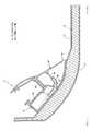
図3は、アクセルペダル4の構造を示す側断面図である。上述したフロアパネル13の上面には、防振、遮音および断熱機能等を有するメルシート、フェルト材またはグラスウール等を主体としたインシュレータ16と、その上面を被覆する従来周知のフロアマット17とが設置されている。 FIG. 3 is a side sectional view showing the structure of the accelerator pedal 4. On the upper surface of the
自動車Vでは、ブレーキペダル5およびクラッチペダル6が吊り下げ式ペダルにより構成される一方、アクセルペダル4は、フロアパネル13側に固定されたベース部材41と、このベース部材41により支持されると共に、乗員の踏み込み操作に応じて下端ヒンジ部42を支点に揺動する踏面板43と、この踏面板43を後方側に付勢する圧縮コイルばね等からなる付勢部材44とを備えており、揺動中心となる下端ヒンジ部42が踏面板43の踏み込み面の下方に設定されたいわゆるオルガン式ペダルにより構成されている。 In the automobile V, the brake pedal 5 and the clutch pedal 6 are constituted by a suspension type pedal, while the accelerator pedal 4 is supported by the base member 41 fixed to the
踏面板43は、下端ヒンジ部42を支点として揺動可能に支持されると共に、通常時(非操作時)には、前記付勢部材44の付勢力に応じ、水平線に対して所定角度の傾斜状態で保持されるようになっている。 The
また、アクセルペダル4は、踏面板43の揺動変位を検出して図外の制御部に検出信号を出力するアクセルペダル操作検出部を備えており、踏面板43の裏面には、前記アクセルペダル操作検出部を構成する操作ロッド45が回動可能に枢支されている。 The accelerator pedal 4 includes an accelerator pedal operation detection unit that detects a swinging displacement of the
ベース部材41には、前記アクセルペダル操作検出部を構成するリニアセンサが配設されたコントロールボックス46と、操作ロッド45の下端部に連結された可撓性を有する線条体等からなる連結部材47を摺動可能に支持するガイド部48とが設けられている。 The base member 41 includes a
アクセルペダル4において、フロアパネル13上に踵部を載置した乗員Mの足Mf(図1参照)を踏面板43の踏み込み面に当接させた状態で、この踏面板43を運転者が踏み込み操作すると、付勢部材44の付勢力に抗して踏面板43が下端ヒンジ部42を揺動中心として車両の前方側へ揺動し、前傾する。この踏面板43に入力された踏み込み力が操作ロッド45および連結部材47を介してコントロールボックス46のリニアセンサに伝達されることにより、踏面板43の操作量が検出され、その検出信号がコントロールボックス46から図外のハーネスを介してパワートレイン用制御ユニットに出力されるようになっている。 In the accelerator pedal 4, the driver steps on the
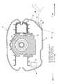
図4は、コラムカバーを示す側面図であり、図5〜図7は、ぞれぞれ、図4のA−A線矢視断面図、B−B線矢視断面図、C−C線矢視断面図である。なお、図中において、矢印(IN)は車体内方、矢印(OUT)は車体外方を示す。本実施形態では、図1、図2、図4〜図7に示すコラムカバー9が、図5〜図7に示すステアリングコラム18を覆っており、ステアリングホイール9の操舵力を車輪W(図2参照)に伝達するステアリングシャフト19(図5〜図7参照)が、上述したステアリングコラム18によって回転可能に支持されている。そして、ステアリングシャフト19の回転力は、図1に示す上部のユニバーサルジョイント20、第2シャフト21、下部のユニバーサルジョイント22等を介して図示しないステアリングギアボックスに伝達されるようになっている。 4 is a side view showing the column cover, and FIGS. 5 to 7 are cross-sectional views taken along lines AA, BB, and CC, respectively, of FIG. It is arrow sectional drawing. In the drawing, the arrow (IN) indicates the inside of the vehicle body, and the arrow (OUT) indicates the outside of the vehicle body. In this embodiment, the column cover 9 shown in FIGS. 1, 2, and 4 to 7 covers the
また、コラムカバー9内には、図5〜図7に示すように、キーシリンダ23や、ステアリングシャフト19の操舵角を検出する舵角センサ24の他、図示しない電動パワーステアリングユニットや、可変ステアリングギアレシオ(VGR)装置等の各種補機が収納されている。 As shown in FIGS. 5 to 7, the column cover 9 has a
また、コラムカバー9は、図1、図2、図4〜図7に示すように、その下面91の、ステアリングシャフト19の軸方向(以下、軸方向と略記する。)L1における下面後端部91aよりも前方で、かつアクセルペダル4側の側部に、下面後端部91aから軸方向L1に延びる延長線L2よりも下方に突出して車両前方に延びる下方延設部92aを有するガイド面92が設けられている。 As shown in FIGS. 1, 2, and 4 to 7, the column cover 9 has a lower surface rear end portion in the axial direction (hereinafter abbreviated as the axial direction) L <b> 1 of the
ガイド面92は、図1、図2、図4、図5に示すように、上方延設部92bを有し、この上方延設部92bは、コラムカバー9の軸方向L1における後端部9aよりも車両前方で、下面後端部91aよりも車両前方の位置から、コラムカバー9のアクセルペダル4側の側部まで側方(車幅方向右方)かつ上方に向かって延設されている。 As shown in FIGS. 1, 2, 4, and 5, the
また、ガイド面92は、図5〜図7に示すように、コラムカバー9のアクセルペダル4側の側面93と車幅方向で反対側の側面94よりも、車幅方向でコラムカバー9の内側に延設されている。そして、コラムカバー9内では、上述した舵角センサ24等の各種補機が、側面94側の内部空間に配設されている。なお、図5〜図7では、側面94と対称の関係になるように側面93′を設けた場合の形状を二点鎖線で示している。 As shown in FIGS. 5 to 7, the
さらに、ガイド面92では、下方延設部92aが、図6、図7に示すように、コラムカバー9の側面94よりも下方に延設されている。 Further, on the
また、コラムカバー9の下面91には、図1、図6、図7に示すように、アクセルペダル4側と反対側の部位に、ステアリングシャフト19(ステアリングホイール7)の位置を調整するチルトレバー25が設けられている。 Further, on the
コラムカバー9内には、図7に示すように、断面門形のブラケット26が配設され、左右一対のチルト用の溝26aが形成されている。そして、ブラケット26の車幅方向一方には、締付け用プレート27と、プレート支持ピン28が配設されると共に、溝26aには、ボルト29が貫通しており、ブラケット26と締付け用プレート27とがボルト29およびナット30によって締結されている。そして、チルト用の溝26aに挿通されたボルト29は、チルトレバー25の操作時に溝26aに対して相対移動可能に配設されている。 In the column cover 9, as shown in FIG. 7, a
このため、ボルト29、ナット30による締結力を緩めることによって、締付け用プレート27の締付けを緩めると共に、ステアリングコラム18をチルトさせると、ボルト29が溝26aに沿って変位し、ステアリングシャフト19を傾動させることができることができるようになっている。 For this reason, by loosening the fastening force by the
次に、図2に示すように、自動車Vが障害物αに前突し、特に、図示のように、障害物αと斜突またはオフセット衝突した場合について説明する。この場合、乗員Mは、車体に対して斜め前方に相対移動し、足Mfを含む脚部Mlが車幅方向左方に相対移動しようする。 Next, as shown in FIG. 2, a case where the automobile V collides forward with the obstacle α, and in particular, as shown in the figure, the vehicle V has an oblique collision or offset collision will be described. In this case, the occupant M moves relatively forward with respect to the vehicle body, and the leg Ml including the foot Mf tends to move relative to the left in the vehicle width direction.
ここで、本実施形態では、乗員Mの脚部Ml(膝Mk)が、コラムカバー9のガイド面92に当接することとなり、具体的には、脚部Mlが、図5にて二点鎖線で示すように、先ず下面後端部91aよりも車両前方に位置する上方延設部92bに当接する。そして、この上方延設部92bによって、脚部Mlが下方延設部92a上にガイドされ、乗員Mの相対移動が進むと、脚部Mlは、図6、図7にて二点鎖線で示すように、下方延設部92aのガイドにより、車体に対して相対的にアクセルペダル4側(車幅方向右方)に移動するようになっている。 Here, in the present embodiment, the leg Ml (knee Mk) of the occupant M comes into contact with the
このように、本実施形態では、コラムカバー9にガイド面92を設け、自動車Vが障害物αに前突した時、このガイド面92によって脚部Mlをアクセルペダル4側へ移動させるようにガイドすることで、図2にて二点鎖線で示すように、アクセルペダル4(踏面板43)に足Mfを乗せた状態(踏み込み操作状態)を保持するようになっている。このため、本実施形態では、自動車Vの前突時に足Mfが滑り易いアクセルペダル4側の脚部Mlが、アクセルペダル4から相対的に車幅方向に移動することをガイド面92によって抑制でき、その結果、足Mfがアクセルペダル4から車幅方向に移動することを抑制できる。 Thus, in this embodiment, the column cover 9 is provided with the
また、本実施形態では、上述したように、揺動中心が踏み込み面の下方に設定され、踏み込み面の踏み込み操作により前傾する所謂オルガン式ペダルでアクセルペダル4を構成している。本実施形態の場合、自動車Vの前突時に足Mfが滑り易いオルガン式ペダル(アクセルペダル4)側の脚部Mlが、オルガン式ペダル(アクセルペダル4)から相対的に車幅方向に移動することをガイド面92によって抑制でき、その結果、足Mfがオルガン式ペダル(アクセルペダル4)から相対的に車幅方向に移動することを抑制できる。 Further, in the present embodiment, as described above, the accelerator pedal 4 is configured by a so-called organ-type pedal whose swing center is set below the stepping surface and tilts forward by a stepping operation on the stepping surface. In the case of the present embodiment, the leg Ml on the side of the organ pedal (accelerator pedal 4) on which the foot Mf is slippery at the time of a frontal collision of the automobile V moves relatively in the vehicle width direction from the organ type pedal (accelerator pedal 4). This can be suppressed by the
ところで、運転席シート1の乗員Mが降車する際には、乗員Mの膝Mkがコラムカバー9の近傍に位置することから、その乗降性は、乗員の膝Mkとコラムカバーとの距離が重要となる。ここで、運転席シート1の乗員Mが降車する際の行動形態(以降、これを降車モードと言う。)について考えてみると、一般的に2つの降車モードが考えられ、乗員Mがブレーキペダル5に足Mfを乗せたまま降車する第1の降車モードと、ブレーキペダル5から足Mfを引いてから降車する第2の降車モードとが考えられる。 By the way, when the occupant M of the driver's
このうち、前記第1の降車モードでは、足Mfをアクセルペダル4に乗せた場合と同様、脚部Mlを車両前方に伸ばした状態になっているため、膝Mkは、図1にて実線で示す場合と同様低い位置にある。従って、前記第1の降車モードでは、膝Mkとコラムカバー9との干渉が起こり難い。 Among these, in the first getting-off mode, as in the case where the foot Mf is put on the accelerator pedal 4, the leg Ml is in a state of extending forward of the vehicle, so that the knee Mk is shown by a solid line in FIG. It is in the lower position as shown. Accordingly, in the first dismounting mode, the knee Mk and the column cover 9 are unlikely to interfere with each other.
一方、前記第2の降車モードでは、特に、乗員Mが長身(例えば、身長175cm以上)である場合、図1にて一点鎖線で示すように、足Mfを車両後方に引くことによって、膝Mkは、第1の降車モードに比べて上方に位置することになる。従って、前記第2の降車モードでは、膝Mkとコラムカバー9とが干渉し易くなる。 On the other hand, in the second dismounting mode, in particular, when the occupant M is tall (for example, 175 cm or more tall), as shown by a one-dot chain line in FIG. Is positioned higher than in the first dismounting mode. Therefore, in the second getting-off mode, the knee Mk and the column cover 9 are likely to interfere with each other.
また、降車モードとしては、図1にて二点鎖線で示すように、臀部Mhを車両前側にずらして着座した乗員Mが、その姿勢を維持したまま降車する第3の降車モードが考えられる。 Moreover, as a getting-off mode, as shown with a dashed-two dotted line in FIG. 1, the 3rd getting-off mode which the passenger | crew M who seated by shifting the collar part Mh to the vehicle front side gets off with the attitude | position maintained can be considered.
この第3の降車モードでは、乗員Mが長身でなかったとしても、臀部Mhが車両前方に位置している分、膝Mkは、第1の降車モードに比べて上方に位置することになり、第2の降車モードと同様、膝Mkとコラムカバー9とが干渉し易くなる。 In this third dismounting mode, even if the occupant M is not tall, the knee Mk is positioned higher than the first dismounting mode, as the hip Mh is positioned in front of the vehicle, As in the second dismounting mode, the knee Mk and the column cover 9 are likely to interfere with each other.
そこで、本実施形態では、上述したように、ガイド面92を、下面後端部91aよりも前方で延長線L2よりも下方に突出するように設けており、換言すれば、車両前方に設けたガイド面92よりも高い位置にコラムカバー9の下面後端部91aを設定している。これにより、膝Mkが比較的上方に位置する第2、第3の降車モードで乗員Mが降車したとしても、膝Mkとコラムカバー9との干渉を回避することができ、その結果、乗降性を確保することができる。 Therefore, in the present embodiment, as described above, the
なお、本実施形態では、前後位置調整機構2を車両前方かつ上方に傾斜するように設けているが、この場合、長身の乗員Mがシートクッション1aを車両後方位置に設定することで、臀部Mhの位置(ヒップポイント)を下方に設定することができ、その分、膝Mkを下方に設定することができる。従って、コラムカバー9にガイド面92を設けた場合には、上述したように、前後位置調整機構2を車両前方かつ上方に傾斜するように設けるのがより好ましい。 In this embodiment, the front / rear position adjustment mechanism 2 is provided so as to be inclined forward and upward in the vehicle. In this case, the tall passenger M sets the
また、本実施形態では、後端部9aよりも車両前方で、下面後端部91aよりも車両前方の位置から、コラムカバー9のアクセルペダル4側の側部まで側方(車幅方向右方)かつ上方に向かって延設される上方延設部92bを設けたことで、延長線L2から下方に突出する下方延設部92aよりも車両後方の位置で可及的早期に脚部Mlをガイドすることができる。このため、脚部Mlがアクセルペダル4から相対的に車幅方向に移動することをより円滑に抑制できる。 In the present embodiment, the vehicle is further forward than the
また、アクセルペダル4側の側面93と車幅方向で反対側の側面94よりも、車幅方向でコラムカバー9の内側に延設するようにガイド面92を設けたことで、アクセルペダル4側の脚部Mlを車幅方向にガイドする範囲を拡大することができる。これにより、自動車Vの前突時、乗員Mの膝Mkが車幅方向にぶれたとしても脚部Mlを安定的にガイドすることができる。 Further, by providing the
そして、アクセルペダル4側のみをコラムカバー9の内側に延設させたことで、アクセルペダル4が配設されていない反対側(側面94側)のコラムカバー9内部では、上述した舵角センサ24等の各種補機を収納するためのスペースを確保することができる。 Then, only the accelerator pedal 4 side is extended to the inside of the column cover 9, so that the above-described
また、側面93と車幅方向で反対側の側面94よりも下方に延設する下方延設部92aを設けたことで、アクセルペダル4が配設されていない反対側(側面94側)では、コラムカバー9が下方に突出しない構成とすることができる。これにより、乗降時における膝Mkの移動スペースを確保することができ、膝Mkとコラムカバー9との干渉をより確実に抑制することができる。 In addition, by providing a lower extending
また、コラムカバー9の下面91において、アクセルペダル4側と反対側の部位にチルトレバー25を設けたことで、ガイド面92のガイド機能を確保しつつ、運転席シート1に乗員Mが着座した時、脚部Mlの周辺がチルトレバー25の存在によって窮屈になることを抑制できる。 Further, the
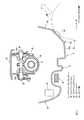
図8は、本発明の他の実施形態に係るステアリングコラムカバー構造を備えた車両前部を示す側面図である。自動車Vの車種によっては、図8に示すインストルメントパネル3のように、コラムカバー9の下部を覆うようにロアパネル31が設けられるものがある。この場合、ガイド面92の下方延設部92aの前端部を、図示のように車両後方に設定してもよい。なお、図8において、図1〜図7に示す先の実施形態と同様の構成要素については、同一の符号を付して説明を省略する。 FIG. 8 is a side view showing a vehicle front portion provided with a steering column cover structure according to another embodiment of the present invention. Depending on the type of the automobile V, there is a type in which a
自動車Vの前突時には、上述したように、乗員Mが車体に対して斜め前方に相対移動するが、実際、コラムカバー9の前端部まで脚部Mlが移動することは少なく、仮に、コラムカバー9の前端部まで脚部Mlが移動したとしても、図8の場合、樹脂製のロアパネル31によって脚部Mlの衝撃を吸収することができる。従って、インストルメントパネル3にロアパネル31を設けた場合には、下方延設部92aの前端部を車両後方に設定することができる。 As described above, at the time of the front collision of the automobile V, the occupant M moves relatively obliquely forward with respect to the vehicle body. However, the leg Ml does not actually move to the front end of the column cover 9, and the column cover is temporarily assumed. Even if the leg Ml moves to the front end portion of FIG. 9, in the case of FIG. 8, the impact of the leg Ml can be absorbed by the resin
また、上述した実施形態では、アクセルペダル4をオルガン式ペダルとしたが、本発明は必ずしもこれに限定されるものではなく、吊り下げ式のアクセルペダルとしてもよい。 In the above-described embodiment, the accelerator pedal 4 is an organ-type pedal, but the present invention is not necessarily limited to this, and may be a suspension-type accelerator pedal.
また、本発明では、上述した実施形態のように、揺動中心(下端ヒンジ部42)が踏み込み面の下方に設定されたものを用いることに必ずしも限定されない。例えば、揺動中心が踏み込み面の上下中心部に設定されたものを用いてもよいし、特開2007−257391号公報に開示されているように、踏み込み面の踏み込み操作により踏面板が実質的に平行移動するものを用いてもよい。 Moreover, in this invention, it is not necessarily limited to using what the rocking | swiveling center (lower-end hinge part 42) was set below the stepping surface like embodiment mentioned above. For example, a rocking center whose center is set at the vertical center of the stepping surface may be used, or as disclosed in Japanese Patent Application Laid-Open No. 2007-257391, the tread plate is substantially formed by stepping on the stepping surface. You may use what moves parallel to.
また、上述した実施形態のように、踏面板43の操作量がリニアセンサで検出されるものを用いることに必ずしも限定されない。例えば、ワイヤを介して踏面板をエンジンのスロットル弁に連結することにより、踏面板の操作量に応じてスロットル弁を開作動させるように構成したものを用いてもよいし、踏面板43の操作量に応じてその下方に位置するボタンの操作量を調整できるように構成したものを用いてもよい。 Moreover, it is not necessarily limited to using what detects the operation amount of the
また、上述した実施形態では、車室前部左側に運転席シート1、コラムカバー9等を設けているが、車室前部右側に運転席シート、コラムカバー等を設けた自動車に本発明を適用してもよい。
また、クラッチペダル6を備えたMT車に限らず、クラッチペダル6を備えていないAT車に本発明を適用してもよい。Further, in the above-described embodiment, the driver's
In addition, the present invention may be applied not only to the MT vehicle provided with the clutch pedal 6 but also to the AT vehicle not provided with the clutch pedal 6.
この発明の構成と、上述の実施形態との対応において、
この発明の、ステアリング位置調整レバーは、チルトレバー25に対応し、
揺動中心は、下端ヒンジ部42に対応するも、この発明は、上述の実施形態の構成のみに限定されるものではなく、多くの実施の形態を得ることができる。In correspondence between the configuration of the present invention and the above-described embodiment,
The steering position adjusting lever of the present invention corresponds to the
Although the swing center corresponds to the lower
4…アクセルペダル
9…ステアリングコラムカバー
18…ステアリングコラム
19…ステアリングシャフト
25…チルトレバー(ステアリング位置調整レバー)
42…下端ヒンジ部(揺動中心)
91a…下面後端部
92…ガイド面(斜面)
L1…ステアリングシャフト軸方向
L2…延長線4 ... Accelerator pedal 9 ... Steering column cover 18 ...
42 ... lower end hinge part (swing center)
91a ...
L1 ... Steering shaft axial direction L2 ... Extension line
Claims (3)
Translated fromJapanese上記ステアリングコラムカバーの下面のうち、前側かつアクセルペダル側の部分に、下方に突出する突出部が形成されており、
上記ステアリングコラムカバーにおけるアクセルペダルがない側の側面と下面とが成す角部を、ステアリングシャフトを通る中心線を対称線として、アクセルペダル側に仮想的に配置したときに、その角部がステアリングコラムカバーの外側に存在するように、上記ステアリングコラムカバーの下面の上記突出部とアクセルペダル側の側面とに面取り状に斜面が形成されていて、該斜面が膝のガイド面として機能することを特徴とする
自動車のステアリングコラムカバー構造。Provide a steering column cover that covers the steering column,
Of the lower surface of the steering column cover, a protruding portion that protrudes downward is formed on the front side and the accelerator pedal side portion,
When the corner formed by the side surface and the lower surface of the steering column cover on the side without the accelerator pedal is virtually arranged on the accelerator pedal side with the center line passing through the steering shaft as the symmetry line, the corner portion is the steering column. A slope is formed in a chamfered shape on the projecting portion of the lower surface of the steering column cover and the side surface on the accelerator pedal side so as to exist outside the cover, and the slope functions as a guide surface for the knee. to <br/> steering column coverstructure of theautomobile.
請求項1に記載の自動車のステアリングコラムカバー構造。On the lower surface of the steering column cover, a steering position adjusting lever is provided at a portion opposite to the pedal side.
The steering column cover structure foran automobile accordingto claim 1 .
請求項1に記載のステアリングコラムカバー構造を備えた自動車。
Theautomobile provided with thesteering column cover structure according to claim1,wherein the accelerator pedal is a pedal whose swing center is set at a vertical center or a lower side of a stepping surface.
Priority Applications (4)
| Application Number | Priority Date | Filing Date | Title |
|---|---|---|---|
| JP2011223624AJP5853566B2 (en) | 2011-10-11 | 2011-10-11 | Automobile steering column cover structure and automobile equipped with the steering column cover structure |
| DE201210019587DE102012019587A1 (en) | 2011-10-11 | 2012-10-05 | Steering column cover structure for a vehicle and assembly method for this |
| CN201210380050.8ACN103043090B (en) | 2011-10-11 | 2012-10-09 | Car steering tube column cover arrangement |
| US13/648,071US8820810B2 (en) | 2011-10-11 | 2012-10-09 | Steering column cover structure of automotive vehicle |
Applications Claiming Priority (1)
| Application Number | Priority Date | Filing Date | Title |
|---|---|---|---|
| JP2011223624AJP5853566B2 (en) | 2011-10-11 | 2011-10-11 | Automobile steering column cover structure and automobile equipped with the steering column cover structure |
Publications (2)
| Publication Number | Publication Date |
|---|---|
| JP2013082326A JP2013082326A (en) | 2013-05-09 |
| JP5853566B2true JP5853566B2 (en) | 2016-02-09 |
Family
ID=47908978
Family Applications (1)
| Application Number | Title | Priority Date | Filing Date |
|---|---|---|---|
| JP2011223624AExpired - Fee RelatedJP5853566B2 (en) | 2011-10-11 | 2011-10-11 | Automobile steering column cover structure and automobile equipped with the steering column cover structure |
Country Status (4)
| Country | Link |
|---|---|
| US (1) | US8820810B2 (en) |
| JP (1) | JP5853566B2 (en) |
| CN (1) | CN103043090B (en) |
| DE (1) | DE102012019587A1 (en) |
Families Citing this family (47)
| Publication number | Priority date | Publication date | Assignee | Title |
|---|---|---|---|---|
| JP5620841B2 (en)* | 2011-02-04 | 2014-11-05 | 株式会社山田製作所 | Steering device |
| EP2907730B1 (en) | 2014-01-29 | 2017-09-06 | Steering Solutions IP Holding Corporation | Hands on steering wheel detect |
| US9669788B2 (en)* | 2014-10-03 | 2017-06-06 | GM Global Technology Operations LLC | Knee airbag for motor vehicle |
| US10589774B2 (en) | 2015-05-01 | 2020-03-17 | Steering Solutions Ip Holding Corporation | Counter rotation steering wheel |
| US10351159B2 (en) | 2015-05-01 | 2019-07-16 | Steering Solutions Ip Holding Corporation | Retractable steering column with a radially projecting attachment |
| US9919724B2 (en) | 2015-05-29 | 2018-03-20 | Steering Solutions Ip Holding Corporation | Retractable steering column with manual retrieval |
| US11560169B2 (en) | 2015-06-11 | 2023-01-24 | Steering Solutions Ip Holding Corporation | Retractable steering column system and method |
| US10343706B2 (en) | 2015-06-11 | 2019-07-09 | Steering Solutions Ip Holding Corporation | Retractable steering column system, vehicle having the same, and method |
| DE102016110791A1 (en) | 2015-06-15 | 2016-12-15 | Steering Solutions Ip Holding Corporation | Gesture control for a retractable steering wheel |
| CN106256651B (en) | 2015-06-16 | 2019-06-04 | 操纵技术Ip控股公司 | Retractable steering column assembly and method |
| US9828016B2 (en) | 2015-06-24 | 2017-11-28 | Steering Solutions Ip Holding Corporation | Retractable steering column system, vehicle having the same, and method |
| US20160375931A1 (en) | 2015-06-25 | 2016-12-29 | Steering Solutions Ip Holding Corporation | Rotation control system for a steering wheel and method |
| DE102016111473A1 (en) | 2015-06-25 | 2016-12-29 | Steering Solutions Ip Holding Corporation | STATIONARY STEERING WHEEL ASSEMBLY AND METHOD |
| US10112639B2 (en) | 2015-06-26 | 2018-10-30 | Steering Solutions Ip Holding Corporation | Vehicle steering arrangement and method of making same |
| US9840271B2 (en) | 2015-06-29 | 2017-12-12 | Steering Solutions Ip Holding Corporation | Retractable steering column with rake limiter |
| US9849904B2 (en) | 2015-07-31 | 2017-12-26 | Steering Solutions Ip Holding Corporation | Retractable steering column with dual actuators |
| US9845106B2 (en) | 2015-08-31 | 2017-12-19 | Steering Solutions Ip Holding Corporation | Overload protection for belt drive mechanism |
| US10160472B2 (en) | 2015-10-20 | 2018-12-25 | Steering Solutions Ip Holding Corporation | Steering column with stationary hub |
| US9809155B2 (en) | 2015-10-27 | 2017-11-07 | Steering Solutions Ip Holding Corporation | Retractable steering column assembly having lever, vehicle having retractable steering column assembly, and method |
| US10029725B2 (en) | 2015-12-03 | 2018-07-24 | Steering Solutions Ip Holding Corporation | Torque feedback system for a steer-by-wire vehicle, vehicle having steering column, and method of providing feedback in vehicle |
| US10496102B2 (en) | 2016-04-11 | 2019-12-03 | Steering Solutions Ip Holding Corporation | Steering system for autonomous vehicle |
| DE102017108692B4 (en) | 2016-04-25 | 2024-09-26 | Steering Solutions Ip Holding Corporation | Control of an electric power steering system using system state predictions |
| US9994178B2 (en)* | 2016-05-17 | 2018-06-12 | Autoliv Asp, Inc. | Displaceable steering wheel safety systems and related methods |
| US10351161B2 (en) | 2016-05-27 | 2019-07-16 | Steering Solutions Ip Holding Corporation | Steering column with manual retraction |
| CN107521547B (en) | 2016-06-21 | 2020-03-10 | 操纵技术Ip控股公司 | Self-locking telescopic actuator for steering column assembly |
| US10457313B2 (en) | 2016-06-28 | 2019-10-29 | Steering Solutions Ip Holding Corporation | ADAS wheel locking device |
| US10363958B2 (en) | 2016-07-26 | 2019-07-30 | Steering Solutions Ip Holding Corporation | Electric power steering mode determination and transitioning |
| US10160477B2 (en) | 2016-08-01 | 2018-12-25 | Steering Solutions Ip Holding Corporation | Electric power steering column assembly |
| US10189496B2 (en)* | 2016-08-22 | 2019-01-29 | Steering Solutions Ip Holding Corporation | Steering assembly having a telescope drive lock assembly |
| US10384708B2 (en) | 2016-09-12 | 2019-08-20 | Steering Solutions Ip Holding Corporation | Intermediate shaft assembly for steer-by-wire steering system |
| US10160473B2 (en) | 2016-09-13 | 2018-12-25 | Steering Solutions Ip Holding Corporation | Steering column decoupling system |
| US10399591B2 (en) | 2016-10-03 | 2019-09-03 | Steering Solutions Ip Holding Corporation | Steering compensation with grip sensing |
| US10239552B2 (en) | 2016-10-14 | 2019-03-26 | Steering Solutions Ip Holding Corporation | Rotation control assembly for a steering column |
| US10481602B2 (en) | 2016-10-17 | 2019-11-19 | Steering Solutions Ip Holding Corporation | Sensor fusion for autonomous driving transition control |
| US10421475B2 (en) | 2016-11-15 | 2019-09-24 | Steering Solutions Ip Holding Corporation | Electric actuator mechanism for retractable steering column assembly with manual override |
| US10310605B2 (en) | 2016-11-15 | 2019-06-04 | Steering Solutions Ip Holding Corporation | Haptic feedback for steering system controls |
| US9862403B1 (en) | 2016-11-29 | 2018-01-09 | Steering Solutions Ip Holding Corporation | Manually retractable steering column assembly for autonomous vehicle |
| US10351160B2 (en) | 2016-11-30 | 2019-07-16 | Steering Solutions Ip Holding Corporation | Steering column assembly having a sensor assembly |
| US10780915B2 (en) | 2016-12-07 | 2020-09-22 | Steering Solutions Ip Holding Corporation | Vehicle steering system having a user experience based automated driving to manual driving transition system and method |
| US10370022B2 (en) | 2017-02-13 | 2019-08-06 | Steering Solutions Ip Holding Corporation | Steering column assembly for autonomous vehicle |
| DE102017107437B4 (en)* | 2017-04-06 | 2021-09-09 | Ford-Werke Gmbh | Protective cover for a steering spindle, pedal unit and motor vehicle running through a footwell |
| US10449927B2 (en) | 2017-04-13 | 2019-10-22 | Steering Solutions Ip Holding Corporation | Steering system having anti-theft capabilities |
| GB2566704A (en)* | 2017-09-21 | 2019-03-27 | Ford Global Tech Llc | A steering assembly |
| JP6881257B2 (en)* | 2017-11-28 | 2021-06-02 | トヨタ自動車株式会社 | Vehicle pedal device |
| US10875566B2 (en) | 2018-03-22 | 2020-12-29 | Steering Solutions Ip Holding Corporation | Stow release assembly for a manually adjustable steering column assembly |
| US10974756B2 (en) | 2018-07-31 | 2021-04-13 | Steering Solutions Ip Holding Corporation | Clutch device latching system and method |
| US11292504B2 (en)* | 2019-03-20 | 2022-04-05 | Volvo Car Corporation | Vehicle having multiple driving positions |
Family Cites Families (17)
| Publication number | Priority date | Publication date | Assignee | Title |
|---|---|---|---|---|
| US3897848A (en)* | 1973-10-15 | 1975-08-05 | Gen Motors Corp | Occupant knee restraint |
| JPS5713357U (en)* | 1980-06-30 | 1982-01-23 | ||
| JPS61103274U (en)* | 1984-12-12 | 1986-07-01 | ||
| JPS649048A (en)* | 1987-07-02 | 1989-01-12 | Nissan Motor | Passenger protecting device |
| JPH07110610B2 (en)* | 1987-12-18 | 1995-11-29 | 本田技研工業株式会社 | Vehicle steering column fixing part structure |
| JPH0747227Y2 (en)* | 1989-06-30 | 1995-11-01 | マツダ株式会社 | Car instrument panel structure |
| JPH0383151U (en)* | 1989-12-15 | 1991-08-23 | ||
| JP3174688B2 (en)* | 1994-03-31 | 2001-06-11 | 日産車体株式会社 | Column cover |
| JP4056834B2 (en)* | 2002-09-10 | 2008-03-05 | 豊田合成株式会社 | Driver protection device |
| KR100559681B1 (en) | 2003-09-01 | 2006-03-10 | 기아자동차주식회사 | Shock-absorbing structure of steering column cover for automobile |
| JP4432464B2 (en)* | 2003-11-11 | 2010-03-17 | 日産自動車株式会社 | Crew protection device |
| JP2005199734A (en)* | 2004-01-13 | 2005-07-28 | Toyota Motor Corp | Steering shaft cover |
| JP2007257391A (en)* | 2006-03-24 | 2007-10-04 | Denso Corp | Pedal device |
| JP2008120106A (en) | 2006-11-08 | 2008-05-29 | Toyota Motor Corp | Knee airbag device for vehicle |
| KR100897262B1 (en)* | 2006-12-07 | 2009-05-14 | 현대자동차주식회사 | Steering column of car |
| JP2009154603A (en)* | 2007-12-25 | 2009-07-16 | Toyoda Gosei Co Ltd | Air bag device for knee protection |
| JP2011073600A (en)* | 2009-09-30 | 2011-04-14 | Mazda Motor Corp | Driving posture adjusting device for vehicle |
- 2011
- 2011-10-11JPJP2011223624Apatent/JP5853566B2/ennot_activeExpired - Fee Related
- 2012
- 2012-10-05DEDE201210019587patent/DE102012019587A1/ennot_activeWithdrawn
- 2012-10-09USUS13/648,071patent/US8820810B2/ennot_activeExpired - Fee Related
- 2012-10-09CNCN201210380050.8Apatent/CN103043090B/ennot_activeExpired - Fee Related
Also Published As
| Publication number | Publication date |
|---|---|
| US20130087006A1 (en) | 2013-04-11 |
| CN103043090A (en) | 2013-04-17 |
| DE102012019587A1 (en) | 2013-04-11 |
| CN103043090B (en) | 2015-08-19 |
| US8820810B2 (en) | 2014-09-02 |
| JP2013082326A (en) | 2013-05-09 |
Similar Documents
| Publication | Publication Date | Title |
|---|---|---|
| JP5853566B2 (en) | Automobile steering column cover structure and automobile equipped with the steering column cover structure | |
| JP4770964B2 (en) | Car driver's seat floor structure | |
| JP4221160B2 (en) | Backward displacement suppression mechanism for operation pedal | |
| JP2011201510A (en) | Vehicle floor panel structure | |
| JP2009126337A (en) | Vehicle footrest | |
| JP7447398B2 (en) | Driving aid device | |
| JP5724562B2 (en) | Front structure of vehicle compartment | |
| JP2008265464A (en) | Pedal structure for vehicles | |
| JP2011243165A (en) | Operation pedal mounting structure for vehicle | |
| JP2003025864A (en) | Mounting structure of accelerator pedal device | |
| JPH10323258A (en) | Vehicle seat | |
| GB2241050A (en) | Vehicle foot pedal mounting | |
| JP2012234375A (en) | Pedal device for vehicle | |
| JP2014229162A (en) | Vehicle pedal device | |
| JP2012234376A (en) | Pedal device for vehicle | |
| JP5589490B2 (en) | Vehicle floor panel structure | |
| JP5287781B2 (en) | Knee airbag device for vehicle | |
| JP3776225B2 (en) | Brake pedal structure of automobile | |
| JP4096723B2 (en) | Accelerator pedal mounting bracket | |
| JP2011204193A (en) | Pedal device for vehicle | |
| JP7413984B2 (en) | vehicle | |
| JP2012238287A (en) | Vehicular pedal device | |
| JP2011207417A (en) | Knee air bag device for vehicle | |
| JP2008189030A (en) | Vehicle structure | |
| JP5589495B2 (en) | Vehicle floor mat mounting structure |
Legal Events
| Date | Code | Title | Description |
|---|---|---|---|
| A621 | Written request for application examination | Free format text:JAPANESE INTERMEDIATE CODE: A621 Effective date:20140819 | |
| A977 | Report on retrieval | Free format text:JAPANESE INTERMEDIATE CODE: A971007 Effective date:20150519 | |
| A131 | Notification of reasons for refusal | Free format text:JAPANESE INTERMEDIATE CODE: A131 Effective date:20150526 | |
| A521 | Request for written amendment filed | Free format text:JAPANESE INTERMEDIATE CODE: A523 Effective date:20150727 | |
| A131 | Notification of reasons for refusal | Free format text:JAPANESE INTERMEDIATE CODE: A131 Effective date:20150908 | |
| A521 | Request for written amendment filed | Free format text:JAPANESE INTERMEDIATE CODE: A523 Effective date:20151021 | |
| TRDD | Decision of grant or rejection written | ||
| A01 | Written decision to grant a patent or to grant a registration (utility model) | Free format text:JAPANESE INTERMEDIATE CODE: A01 Effective date:20151110 | |
| A61 | First payment of annual fees (during grant procedure) | Free format text:JAPANESE INTERMEDIATE CODE: A61 Effective date:20151123 | |
| R150 | Certificate of patent or registration of utility model | Ref document number:5853566 Country of ref document:JP Free format text:JAPANESE INTERMEDIATE CODE: R150 | |
| LAPS | Cancellation because of no payment of annual fees |