JP5852182B2 - Detachable structure, electronic equipment and accessories - Google Patents
Detachable structure, electronic equipment and accessoriesDownload PDFInfo
- Publication number
- JP5852182B2 JP5852182B2JP2014133685AJP2014133685AJP5852182B2JP 5852182 B2JP5852182 B2JP 5852182B2JP 2014133685 AJP2014133685 AJP 2014133685AJP 2014133685 AJP2014133685 AJP 2014133685AJP 5852182 B2JP5852182 B2JP 5852182B2
- Authority
- JP
- Japan
- Prior art keywords
- attachment
- detachment
- electronic device
- engagement
- accessory
- Prior art date
- Legal status (The legal status is an assumption and is not a legal conclusion. Google has not performed a legal analysis and makes no representation as to the accuracy of the status listed.)
- Active
Links
Images


Landscapes
- Casings For Electric Apparatus (AREA)
Description
Translated fromJapanese本発明は、電子機器に対する付属器具の着脱構造、該着脱構造を用いて付属器具を着脱可能な電子機器及び該着脱構造を用いて電子機器に着脱される付属器具に関する。 The present invention relates to an attachment / detachment structure for an attachment device to / from an electronic device, an electronic device to / from which the attachment device can be attached / detached using the attachment / detachment structure, and an attachment device attached to / detached from the electronic device using the attachment / detachment structure.
近年、タッチパネル式の液晶ディスプレイを有するタブレット型パーソナルコンピュータ(タブレット型PC)が急速に普及している。タブレット型PCは持ち運びが容易であることから、手で把持した状態で或いは鞄等に収納した状態で持ち運ばれる場面が非常に多い。そこで、タブレット型PCでは持ち運び時等での液晶ディスプレイの保護のため、着脱可能なカバー部材が用いられることがある。 In recent years, tablet personal computers (tablet PCs) having a touch panel type liquid crystal display are rapidly spreading. Since tablet PCs are easy to carry, there are many scenes in which they are carried while being held by hand or stored in a bag or the like. Therefore, a detachable cover member is sometimes used in the tablet PC to protect the liquid crystal display when it is carried.
例えば、特許文献1には、タブレット型PCの液晶ディスプレイを覆うカバー部材をタブレット型PCの筐体に対して磁石を用いて着脱する着脱構造が開示されている。この着脱構造はタブレット型PCの筐体の側面を着脱面とし、この着脱面に埋設された磁石に対してカバー部材側の着脱面に埋設された磁石を吸着させ、これによりタブレット型PCにカバー部材を着脱可能としたものである。 For example, Patent Document 1 discloses an attachment / detachment structure in which a cover member that covers a liquid crystal display of a tablet PC is attached to and detached from the housing of the tablet PC using a magnet. In this attachment / detachment structure, the side surface of the case of the tablet PC is used as the attachment / detachment surface, and the magnet embedded in the attachment / detachment surface on the cover member side is attracted to the magnet embedded in the attachment / detachment surface, thereby covering the tablet PC. The member is detachable.
上記特許文献1の構成では、カバー部材を磁力でタブレット型PCに装着するため、その着脱が容易である。従って、例えば、持ち運び時以外にはカバー部材を外しておきたいユーザや、カバー部材を液晶ディスプレイのクリーナーとして利用するユーザ等にとっては非常に利便性の高いものとなっている。 In the configuration of Patent Document 1, since the cover member is attached to the tablet PC with a magnetic force, it can be easily attached and detached. Therefore, for example, it is very convenient for a user who wants to remove the cover member except when carrying it, a user who uses the cover member as a liquid crystal display cleaner, and the like.
ところが、この構成では、カバー部材を磁力のみでタブレット型PCに装着しているため、カバー部材に対する力のかかり具合によってはカバー部材が容易に外れてしまうことがある。例えば、磁石同士の吸着方向に沿った外力に対してはカバー部材は容易に外れることはないが、吸着方向に垂直な方向の外力が付与されると簡単に外れてしまう。 However, in this configuration, since the cover member is attached to the tablet PC only by the magnetic force, the cover member may be easily detached depending on the degree of force applied to the cover member. For example, the cover member does not easily come off with respect to the external force along the attracting direction between the magnets, but it easily comes off when an external force in a direction perpendicular to the attracting direction is applied.
また、特許文献1の構成では、カバー部材を側面視三角形状に折り曲げ変形させることでタブレット型PCのスタンドとして機能させることができる。ところが、このようなスタントを用いてタブレット型PCを起立姿勢に保持した状態では、液晶ディスプレイに対するタッチ操作の押圧方向が前記吸着方向に垂直な方向となる場合がある。そうすると、タッチ操作時にスタンドが倒れてしまう懸念もある。 Moreover, in the structure of patent document 1, it can be made to function as a stand of a tablet-type PC by bending and deforming a cover member in the shape of a triangle in a side view. However, when the tablet PC is held in an upright position using such a stunt, the pressing direction of the touch operation on the liquid crystal display may be a direction perpendicular to the suction direction. Then, there is a concern that the stand may fall down during the touch operation.
本発明は、上記従来技術の課題を考慮してなされたものであり、電子機器に対して付属器具を容易に着脱することができ、しかも高い保持力を持って装着することができる着脱構造、該着脱構造を用いて付属器具を着脱可能な電子機器及び該着脱構造を用いて電子機器に着脱される付属器具を提供することを目的とする。 The present invention has been made in consideration of the above-described problems of the prior art, and is capable of easily attaching / detaching an accessory to / from an electronic device, and can be attached with a high holding force, It is an object of the present invention to provide an electronic device in which an attachment device can be attached / detached using the attachment / detachment structure and an attachment device attached / detached to / from the electronic device using the attachment / detachment structure.
本発明に係る着脱構造は、電子機器に対する付属器具の着脱構造であって、前記電子機器及び前記付属器具のいずれか一方の着脱面から突出した係合凸部と、いずれか他方の着脱面に設けられ、前記係合凸部を挿脱可能な着脱口及び該着脱口と連通形成されて該着脱口に挿入された前記係合凸部をスライドさせた場合に該係合凸部と係合可能な係合凹部とを有する係合機構と、前記電子機器及び前記付属器具のいずれか一方に設けられた磁石と、いずれか他方に設けられて前記磁石と吸着可能な磁石又は被吸着体とを有し、前記係合凸部と前記係合凹部とが係合した状態では前記磁石と前記磁石又は被吸着体とが吸着した状態となる吸着機構とを備えることを特徴とする。 An attachment / detachment structure according to the present invention is an attachment / detachment structure for an attachment device to / from an electronic device, the engagement protrusion projecting from one attachment / detachment surface of the electronic device or the attachment device, and the other attachment / detachment surface. An attachment / detachment port provided and detachable from the engagement projection, and engaged with the engagement projection when the engagement projection formed in communication with the attachment / detachment port is slid. An engaging mechanism having a possible engaging recess; a magnet provided in one of the electronic device and the accessory; a magnet provided on either the other and capable of adsorbing the magnet or an object to be adsorbed; And an attracting mechanism in which the magnet and the magnet or the attracted body are attracted when the engaging convex portion and the engaging concave portion are engaged with each other.
このような構成によれば、電子機器と付属器具との間を係合機構での機械的な連結構造と吸着機構での磁力による吸着構造とで装着することができるため、電子機器に対して高い保持力を持って装着することができる。しかも、係合機構は係合凸部を係合凹部に対してスライドさせるだけで係脱できるため、着脱も容易である。 According to such a configuration, the electronic device and the accessory device can be mounted with a mechanical connection structure with an engagement mechanism and an adsorption structure with a magnetic force with an adsorption mechanism. Can be mounted with high holding power. Moreover, since the engagement mechanism can be engaged and disengaged simply by sliding the engagement convex portion with respect to the engagement concave portion, it is easy to attach and detach.
前記係合凸部は、先端に厚肉部を有する板状部材であり、前記着脱口は、前記係合凸部の厚肉部を挿脱可能な開口幅を有し、前記係合凹部は、前記着脱口に挿入された前記係合凸部をスライドさせた場合に前記厚肉部をスライド方向に挿脱可能な拡幅部を有すると共に、該拡幅部に挿入された前記厚肉部を前記スライド方向と交差する方向に係止可能な開口幅を有し、前記着脱口と一体に形成されていると、簡素な構成で係合機構を構築することができる。 The engaging convex part is a plate-like member having a thick part at the tip, the attachment / detachment opening has an opening width into which the thick part of the engaging convex part can be inserted and removed, and the engaging concave part is When the engagement convex portion inserted in the attachment / detachment port is slid, the thick portion has a widened portion that can be inserted and removed in the sliding direction, and the thick portion inserted in the widened portion is When the opening width that can be locked in the direction intersecting the sliding direction is formed integrally with the attachment / detachment port, the engagement mechanism can be constructed with a simple configuration.
前記付属器具には前記係合凸部が設けられ、前記電子機器には前記着脱口及び前記係合凹部が設けられていると、電子機器の外面に凸形状が形成されることを回避できる。 If the accessory device is provided with the engaging convex portion and the electronic device is provided with the attachment / detachment opening and the engaging concave portion, it is possible to avoid the formation of a convex shape on the outer surface of the electronic device.
前記吸着機構は、前記電子機器に設けられ、前記係合凸部のスライド方向に沿って複数並べられると共にN極とS極とが交互に配置された前記磁石と、前記付属器具に設けられ、前記係合凸部のスライド方向に沿って複数並べられると共にN極とS極とが交互に配置された前記磁石とを有し、前記係合凸部と前記係合凹部とが係合した状態では、前記電子機器に設けられた磁石のN極及びS極と前記付属器具に設けられた磁石のS極及びN極とが互いに対面配置されて吸着した状態となるとよい。そうすると、電子機器に対する付属器具の装着状態を確実に保持することができる。また、磁石のN極とS極が交互に並べられているため、互いの吸着力及び反発力を利用して付属器具をスライドさせることができ、着脱動作が一層円滑なものとなる。 The adsorption mechanism is provided in the electronic device, and is provided in the accessory, the magnet in which a plurality of N-poles and S-poles are alternately arranged along the sliding direction of the engagement convex part, A plurality of magnets arranged in a line along the sliding direction of the engaging projections and alternately arranged with north and south poles, and the engaging projections and the engaging recesses are engaged with each other Then, it is good that the N pole and S pole of the magnet provided in the electronic device and the S pole and N pole of the magnet provided in the accessory are arranged to face each other and attracted. If it does so, the mounting state of the accessory with respect to an electronic device can be hold | maintained reliably. Moreover, since the N pole and the S pole of the magnet are alternately arranged, the attachment device can be slid using the mutual attractive force and repulsive force, and the attachment / detachment operation becomes smoother.
この場合、前記係合凸部と前記係合凹部とが係合していない状態では、前記電子機器に設けられた磁石と前記付属器具に設けられた磁石とは、少なくとも一部で互いのN極及びN極と互いのS極及びS極とが対面配置されて反発した状態となると、磁石の反発力を確実に発生させることができ、付属器具の着脱が一層円滑なものとなる。 In this case, in a state where the engagement convex portion and the engagement concave portion are not engaged, at least a part of the magnet provided in the electronic device and the magnet provided in the accessory is a mutual N. When the poles and N poles and the S poles and S poles of each other are arranged facing each other and repelled, the repulsive force of the magnet can be generated with certainty, and attachment and detachment of the accessory becomes smoother.
本発明に係る電子機器は、上記構成の着脱構造を用いて前記付属器具を着脱可能に構成したことを特徴とする。 The electronic apparatus according to the present invention is characterized in that the attachment device is configured to be detachable using the detachable structure having the above-described configuration.
この場合、前記付属器具は、前記電子機器に設けられたディスプレイ装置を覆うカバー部材であってもよい。 In this case, the accessory may be a cover member that covers a display device provided in the electronic apparatus.
前記カバー部材は、折り曲げて変形させることで当該電子機器を起立姿勢に保持するスタンド部材として機能するものであってもよい。この構成の場合にも、係合機構と吸着機構を備えた着脱構造によって電子機器にスタンド部材となるカバー部材が強固に固定されるため、スタンド部材によって起立させた電子機器を操作しても容易に倒れることがない。 The cover member may function as a stand member that holds the electronic device in a standing posture by being bent and deformed. Even in this configuration, since the cover member serving as the stand member is firmly fixed to the electronic device by the detachable structure including the engagement mechanism and the suction mechanism, it is easy to operate the electronic device raised by the stand member. Will not fall over.
本発明に係る付属器具は、上記構成の着脱構造を用いて前記電子機器に着脱されることを特徴とする。 The accessory according to the present invention is attached to and detached from the electronic device using the attachment / detachment structure having the above-described configuration.
この場合、前記係合凸部及び前記磁石が設けられた装着部と、前記電子機器に設けられたディスプレイ装置を覆うカバー部と、前記装着部と前記カバー部との間を折り曲げ可能に連接する連接部とを備える構成であってもよい。 In this case, the mounting portion provided with the engaging convex portion and the magnet, the cover portion covering the display device provided in the electronic device, and the mounting portion and the cover portion are connected so as to be bendable. The structure provided with a connection part may be sufficient.
前記カバー部を折り曲げて変形させることで前記電子機器を起立姿勢に保持するスタンド部材として機能するもの構成であってもよい。 It may be configured to function as a stand member that holds the electronic device in an upright posture by bending and deforming the cover portion.
本発明によれば、電子機器と付属器具との間を係合機構での機械的な連結構造と吸着機構での磁力による吸着構造とで装着することができるため、電子機器に対して高い保持力を持って装着することができる。しかも、係合機構は係合凸部を係合凹部に対してスライドさせるだけで係脱できるため、着脱も容易である。 According to the present invention, the electronic device and the accessory can be mounted with a mechanical connection structure with an engagement mechanism and an adsorption structure with a magnetic force with an adsorption mechanism, so that the electronic device has a high holding capacity. Can be worn with power. Moreover, since the engagement mechanism can be engaged and disengaged simply by sliding the engagement convex portion with respect to the engagement concave portion, it is easy to attach and detach.
以下、本発明に係る着脱構造について、この構造を備える電子機器及び付属器具との関係で好適な実施の形態を挙げ、添付の図面を参照しながら詳細に説明する。 DESCRIPTION OF THE PREFERRED EMBODIMENTS Hereinafter, a detachable structure according to the present invention will be described in detail with reference to the accompanying drawings by giving preferred embodiments in relation to an electronic device and an accessory provided with this structure.
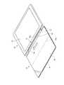
図1は、本発明の一実施形態に係る電子機器10に対して着脱構造12を用いてカバー部材14を装着した状態を示す斜視図である。本実施形態では、タブレット型PCである電子機器10に対し、付属器具であるカバー部材14を着脱構造12によって着脱する構成を例示する。電子機器10はスマートフォン等でもよく、付属器具は無線又は有線によって電子機器10と接続されるキーボード装置等でもよい。 FIG. 1 is a perspective view showing a state in which a
電子機器10は、タッチパネル式の液晶ディスプレイからなるディスプレイ装置16を備え、筐体内部に基板、演算装置、メモリ等の各種電子部品を収納した公知のものを使用可能である。電子機器10は、その一側面がカバー部材14の着脱面10aとなっている。 The
カバー部材14は、電子機器10に対する装着部18と、ディスプレイ装置16を覆うためのカバー部20と、装着部18とカバー部20との間を折り曲げ可能に連接する連接部22とを備える。 The
装着部18は、電子機器10の着脱面10aに接続される矩形の棒状部材であり、着脱面10aに当接する面が電子機器10に対する着脱面18aとなる。装着部18はある程度の剛性を持った部材であり、アルミニウム等の金属や硬質の樹脂で形成されている。 The mounting
カバー部20は、電子機器10のディスプレイ装置16が設けられた面を覆うことができる薄板状のカバーであり(図2参照)、平面視で電子機器10と略同一の外形を有した矩形形状である。カバー部20は、例えば中心付近に折り曲げ線20aが設けられ、開放端部にゴム材料等からなる滑り止め部材24が設けられている。カバー部材14は、折り曲げ線20aによってカバー部20を2つ折りに折り曲げ、滑り止め部材24を電子機器10の背面に当接させることにより、電子機器10を机の上等で起立姿勢に保持するスタンド部材として機能する(図3参照)。折り曲げ線20aは、例えば2本並列されてもよく、この場合はカバー部20を3つ折りのスタンド部材として機能させることができる。カバー部材14には、ガラスエポキシ樹脂やポリカーボネイト、カーボン等からなる薄い平板を芯材とし、その周囲を皮革や人工皮革、布等で囲繞したものを用いるとよく、連接部22についても同様でよい。 The
連接部22は、装着部18とカバー部材14との間を折り曲げ可能に連接する部分であり、折り曲げ方向に沿って複数の折り曲げ線が形成されている。連接部22を折り曲げることにより、電子機器10に装着部18を装着した状態でカバー部材14を電子機器10の表面に対して開閉し、さらにはカバー部材14を電子機器10の背面側に移動させてスタンド部材として機能させることができる。 The connecting
次に、本実施形態に係る着脱構造12の構成及びこの着脱構造12を用いたカバー部材14の電子機器10への着脱動作について説明する。 Next, the configuration of the attaching / detaching
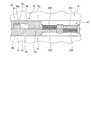
図4は、本発明の一実施形態に係る着脱構造12の構成を示す説明図であり、カバー部材14を電子機器10に装着する前の状態を示す図である。図5は、図4に示す状態からカバー部材14の着脱面18aを電子機器10の着脱面10aに当接させた状態を示す説明図であり、図6は、図5に示す状態からカバー部材14をスライドさせて着脱動作を完了した状態を示す説明図である。また、図8〜図10は、それぞれ図4(A)〜図6(A)に対応した要部拡大図である。 FIG. 4 is an explanatory diagram showing a configuration of the
図4(A)に示すように、着脱構造12は、電子機器10とカバー部材14とを機械的に着脱する係合機構30と、電子機器10とカバー部材14とを磁力によって着脱する吸着機構32とを備える。 4A, the attachment /
係合機構30は、カバー部材14側に設けられた係合凸部34と、電子機器10側に設けられた着脱口36及び係合凹部38とを有する。 The
係合凸部34は、装着部18の着脱面18aから突出するように左右一対設けられた板状部材である。図4(B)に示すように、係合凸部34は、突出方向に向かって断面形状が拡幅した略台形形状であり、基端よりも板厚の大きな厚肉部34aを先端に有する。係合凸部34の設置数は適宜変更可能であり、着脱口36及び係合凹部38は係合凸部34の設置数と同数設置すればよい。 The engaging
着脱口36は、電子機器10の着脱面10aに左右一対設けられた凹部である。着脱口36は、係合凸部34の厚肉部34aを挿脱可能な幅寸法を持った開口幅を有し、穴の奥まで厚肉部34aを進入可能な内部幅を有する(図5(A)及び図5(B)参照)。従って、電子機器10の着脱面10aに対してカバー部材14の着脱面18aを近づける又は遠ざける方向(着脱方向)に移動させると、厚肉部34aを着脱口36に挿脱することができる。 The attachment /
係合凹部38は、着脱口36と連通するように一体に形成されており、電子機器10の着脱面10aに対して着脱口36と共に開口している(図7参照)。図6(A)、図6(B)及び図7に示すように、係合凹部38は、着脱口36に挿入された係合凸部34をスライドさせた場合にその厚肉部34aをスライド方向に挿脱可能な拡幅部38aを有する。この係合凹部38の開口縁部には、拡幅部38aに挿入された厚肉部34aをスライド方向と直行する方向(着脱方向)に係止可能な開口幅を持った狭幅部38bが形成されている。狭幅部38bは、係合凸部34の基端部は通過可能な開口幅を有する。従って、図7に示すように、係合凹部38と着脱口36は段付きの開口幅を有する1つの溝状凹部として形成されている。 The
次に、吸着機構32は、電子機器10側に設けられた磁石40N,40Sと、カバー部材14側に設けられた磁石42N,42Sとを有する。 Next, the attracting
電子機器10に設けられた磁石40Nは、着脱面10aにN極が臨むように筐体内に埋設された永久磁石であり(図6(C)も参照)、磁石40Sは、着脱面10aにS極が臨むように筐体内に埋設された永久磁石である。吸着機構32の電子機器10側では、磁石40N,40S,40Nの順となるように異なる極の磁石40N,40Sを交互に3個並べた組を、一対の係合凹部38を跨ぐように2組設けている。 The
カバー部材14の装着部18に設けられた磁石42Nは、着脱面18aにN極が臨むように装着部18内に埋設された永久磁石であり、磁石42Sは、着脱面18aにS極が臨むように装着部18内に埋設された永久磁石である(図6(C)も参照)。吸着機構32のカバー部材14側では、磁石42S,42N,42Sの順となるように異なる極の磁石42N,42Sを交互に3個並べた組を、一対の係合凸部34を跨ぐように2組設けている。 The
吸着機構32では、図6(A)及び図10に示すように電子機器10にカバー部材14を装着した状態、つまり係合凸部34と係合凹部38が係合した状態で、互いの磁石40N(40S)と磁石42S(42N)とが対面配置されて吸着した状態となるように各磁石40N,40S,42N,42Sが配置されている。また、吸着機構32では、図5(A)及び図9に示すように電子機器10にカバー部材14を装着する際に係合凸部34が着脱口36に挿入された状態で、互いの磁石40N(40S)と磁石42S(42N)とが半分程度ずれて対面配置された状態となり、互いの磁石40N(40S)と磁石42N(42S)との端部同士が僅かに対面配置された状態となるように各磁石40N,40S,42N,42Sが配置されている。なお、これら磁石40N,40S,42N,42Sの配置順や設置個数は適宜変更可能である。 In the attracting
以上のように構成された着脱構造12を用いて電子機器10にカバー部材14を装着する際には、先ず、図11に示すように、カバー部材14の着脱面18aを電子機器10の着脱面10aに対面させた状態とする。この際、図4(A)及び図8に示すように、カバー部材14の係合凸部34が電子機器10の着脱口36に向かった配置とする。 When the
続いて、図12に示すように、カバー部材14の着脱面18aを電子機器10の着脱面10aに当接させ、係合凸部34を着脱口36に挿入する(図4(B)及び図5(B)も参照)。そうすると、図5(A)及び図9に示すように、電子機器10側の磁石40N(40S)とカバー部材14側の磁石42S(42N)とが半分程度ずれて対面すると共に、互いの磁石40N(40S)と磁石42N(42S)との端部同士が僅かに対面する。そのため、互いの磁石40N(40S)と磁石42S(42N)との間に吸引力が発生する一方、互いの磁石40N(42S)と磁石42N(42S)との間に反発力が発生するため、カバー部材14が図5(A)及び図9中で左側に向かう力を受けて自動的に或いは僅かに手で押圧することで円滑にスライドする。 Subsequently, as shown in FIG. 12, the attaching / detaching
このようにカバー部材14がスライドすると、着脱口36に挿入されている係合凸部34が着脱口36内をスライドし、図6(A)及び図10に示すように、隣接する係合凹部38へと挿入される。この際、係合凹部38は、拡幅部38aによって着脱口36からの係合凸部34のスライドを許容する一方、狭幅部38bによって係合凸部34の厚肉部34aがスライド方向に直行する着脱方向に対して抜け出すことを規制している(図6(B)参照)。このため、図1に示すように、電子機器10とカバー部材14との間は、係合機構30での機械的な連結構造と吸着機構32での磁力による吸着構造とを備えた着脱構造12によって強固に且つ安定した状態で連結固定される。 When the
一方、電子機器10に装着したカバー部材14を取り外す場合には、カバー部材14を装着時とは逆方向(図6(A)及び図10中で右側)にスライドさせる。これにより、図5(A)及び図9に示すように係合凸部34が着脱口36までスライドされると、今度は互いの磁石40N(40S)と磁石42N(42S)との間の反発力によって係合凸部34が着脱口36から容易に押し出されるため、カバー部材14を円滑に取り外すことができる。 On the other hand, when the
以上のように、本実施形態に係る着脱構造12は、カバー部材14の着脱面18aから突出した係合凸部34と、電子機器10の着脱面10aに設けられ、係合凸部34を挿脱可能な着脱口36及び着脱口36と連通形成されて該着脱口36に挿入された係合凸部34をスライドさせた場合に該係合凸部34と係合可能な係合凹部38とを有する係合機構30と、電子機器10に設けられた磁石40N,40Sと、カバー部材14に設けられた磁石42N,42Sとを有し、係合凸部34と係合凹部38とが係合した状態では磁石40N,40Sと磁石42N,42Sとが吸着した状態となる吸着機構32とを備える。 As described above, the attachment /
このように、着脱構造12では、電子機器10とカバー部材14との間を、係合機構30での機械的な連結構造と吸着機構32での磁力による吸着構造とで装着する。従って、例えば吸着機構32での磁力による吸着構造のみの場合に比べてカバー部材14を電子機器10に対してより強固に装着することができる。そのため、例えば図3に示す起立姿勢でディスプレイ装置16を強くタッチ操作した場合に、吸着機構32に対して吸着方向に垂直な方向の外力が加えられた場合であっても、係合機構30の保持作用下に磁石40N,40Sと磁石42N,42Sとの間の吸着状態が外れることがなく、電子機器10が倒れることを防止できる。また、例えば係合機構30での機械的な連結構造のみの場合には、その着脱容易性を考慮すると係合凸部34と係合凹部38との間にある程度のクリアランスが必要であり、装着後にがたつきを生じ、製品品質を低下させる懸念がある。これに対して当該着脱構造12では、係合機構30でのクリアランスによるがたつきを吸着機構32によって抑えることができるため、装着後のがたつきを防止して製品品質を高めることができる。一方、電子機器10に装着されたカバー部材14の取り外しは、カバー部材14を逆方向にスライドさせて着脱口36から係合凸部34を引き抜くだけでよい。従って、着脱構造12によれば、電子機器10に対して付属器具であるカバー部材14を高い保持力を持って装着することができ、しかも容易に着脱することができる。 As described above, in the
また、吸着機構32での磁力による連結構造のみを用いた場合には、十分な装着強度を確保するために磁石40N等をある程度大型化させ或いは設置数を増加させる必要がある。これに対して当該着脱構造12では、吸着機構32での吸着状態を係合機構30で補強できるため、磁石40N等を小型化し或いは設置数を最小限にすることができる。反対に、係合機構30での機械的な連結構造のみを用いた場合には、係合部分でのある程度の爪のかかり量を確保するたに十分なスライド量を確保する必要があり、構造が大型化し易い。これに対し、当該着脱構造12では、係合機構30でがたつきを吸着機構32による磁力によって安定させることができるため、係合凸部34の係合凹部38へのかかり量を最小限としてスライド量を小さくすることができ、小型化・省スペース化が可能となり、小型化の要望の強いタブレット型PCやスマートフォンに好適である。 Further, when only the coupling structure using the magnetic force in the attracting
着脱構造12を構成する吸着機構32では、磁石40N,40Sが交互に並べられ、磁石42N,42Sも交互に並べられると共に、係合凸部34と係合凹部38とが係合した状態では、磁石40N(40S)と磁石42S(42N)とが互いに対面配置されて吸着した状態となる。このため、電子機器10に対するカバー部材14の装着状態を確実に保持することができる。しかも、係合凸部34と係合凹部38とが係合していない状態では、少なくとも一部で磁石40N及び磁石42Nと磁石40S及び磁石42Sとが対面配置されて反発した状態となる。このため、磁石の反発力を確実に発生させることができ、カバー部材14の着脱が一層円滑なものとなる。 In the attracting
なお、本発明は、上記した実施形態に限定されるものではなく、本発明の主旨を逸脱しない範囲で自由に変更できることは勿論である。 It should be noted that the present invention is not limited to the above-described embodiment, and it is needless to say that the present invention can be freely changed without departing from the gist of the present invention.
例えば、上記実施形態では、係合凸部34をカバー部材14に設け、着脱口36及び係合凹部38を電子機器10に設けた構成を例示したが、係合凸部34を電子機器10に設け、着脱口36及び係合凹部38をカバー部材14に設けてもよい。但し、係合凸部34を電子機器10に設けた場合には電子機器10の側面に凸形状が形成されてしまうため、係合凸部34は付属器具であるカバー部材14に設けられることが好ましい。 For example, in the above-described embodiment, the engagement
上記実施形態では、電子機器10及びカバー部材14の両方に磁石40N等を設けた構成を例示したが、磁石は一方のみにあればよく、他方はスチール等の磁石と吸着可能な被吸着体であってもよい。但し、上記した磁石40N,40S,42N,42S間での吸着力や反発力による自動的なスライド動作等を円滑に機能させる場合には、電子機器10及びカバー部材14の両方に磁石40N等を設けておくことが好ましい。 In the above-described embodiment, the configuration in which the
上記実施形態では、係合機構30を構成する係合凸部34として、先端に厚肉部34aを有する板状部材を例示したが、その形状は相手側となる着脱口36に挿入した状態でスライドさせることで係合凹部38と係合可能な形状であれば他の形状であってもよい。例えば、係合凹部の開口を着脱口との連通部分のみに設けることで着脱面10aには直接的に開口していない形状とし、係合凸部の係合凹部側の側面に爪状の突起を設け、着脱口内で係合凸部をスライドさせた際に該突起が係合凹部に係合する構成等としてもよい。 In the said embodiment, although the plate-shaped member which has the
10 電子機器
10a,18a 着脱面
12 着脱構造
14 カバー部材
16 ディスプレイ装置
18 装着部
20 カバー部
22 連接部
20a 折り曲げ線
30 係合機構
32 吸着機構
34 係合凸部
34a 厚肉部
36 着脱口
38 係合凹部
38a 拡幅部
38b 狭幅部
40N,40S,42N,42S 磁石DESCRIPTION OF
Claims (11)
Translated fromJapanese前記電子機器及び前記付属器具のいずれか一方の着脱面から突出した係合凸部と、いずれか他方の着脱面に設けられ、前記係合凸部を挿脱可能な着脱口及び該着脱口と連通形成されて該着脱口に挿入された前記係合凸部をスライドさせた場合に該係合凸部と係合可能な係合凹部とを有する係合機構と、
前記電子機器及び前記付属器具のいずれか一方に設けられた磁石と、いずれか他方に設けられて前記磁石と吸着可能な磁石又は被吸着体とを有し、前記係合凸部と前記係合凹部とが係合した状態では前記磁石と前記磁石又は被吸着体とが吸着した状態となる吸着機構と、
を備えることを特徴とする着脱構造。An attachment / detachment structure for an accessory to / from an electronic device,
An engagement projection protruding from one of the attachment / detachment surfaces of the electronic device and the accessory, an attachment / detachment port provided on the other attachment / detachment surface, and the attachment / detachment port through which the engagement projection can be inserted and removed, and the attachment / detachment port An engagement mechanism having an engagement recess that can be engaged with the engagement protrusion when the engagement protrusion formed in communication and inserted into the attachment / detachment port is slid;
A magnet provided on one of the electronic device and the accessory, and a magnet or an object to be adsorbed which is provided on the other and can be adsorbed to the magnet, and the engagement convex portion and the engagement An adsorption mechanism in which the magnet and the magnet or the object to be adsorbed are adsorbed in a state where the recess is engaged;
A detachable structure comprising:
前記係合凸部は、先端に厚肉部を有する板状部材であり、
前記着脱口は、前記係合凸部の厚肉部を挿脱可能な開口幅を有し、
前記係合凹部は、前記着脱口に挿入された前記係合凸部をスライドさせた場合に前記厚肉部をスライド方向に挿脱可能な拡幅部を有すると共に、該拡幅部に挿入された前記厚肉部を前記スライド方向と交差する方向に係止可能な開口幅を有し、前記着脱口と一体に形成されていることを特徴とする着脱構造。The attachment / detachment structure according to claim 1,
The engaging convex part is a plate-like member having a thick part at the tip,
The attachment / detachment opening has an opening width capable of inserting and removing the thick part of the engagement convex part,
The engaging recess has a widened portion that allows the thick-walled portion to be inserted and removed in a sliding direction when the engaging convex portion inserted into the attachment / detachment port is slid, and the inserted insertion into the widened portion. An attachment / detachment structure having an opening width capable of locking the thick portion in a direction intersecting the sliding direction, and formed integrally with the attachment / detachment opening.
前記付属器具には前記係合凸部が設けられ、
前記電子機器には前記着脱口及び前記係合凹部が設けられていることを特徴とする着脱構造。The attachment / detachment structure according to claim 1 or 2,
The accessory is provided with the engaging projection,
The attachment / detachment structure, wherein the electronic device is provided with the attachment / detachment opening and the engagement recess.
前記吸着機構は、前記電子機器に設けられ、前記係合凸部のスライド方向に沿って複数並べられると共にN極とS極とが交互に配置された前記磁石と、
前記付属器具に設けられ、前記係合凸部のスライド方向に沿って複数並べられると共にN極とS極とが交互に配置された前記磁石とを有し、
前記係合凸部と前記係合凹部とが係合した状態では、前記電子機器に設けられた磁石のN極及びS極と前記付属器具に設けられた磁石のS極及びN極とが互いに対面配置されて吸着した状態となることを特徴とする着脱構造。In the attachment or detachment structure according to any one of claims 1 to 3,
The attraction mechanism is provided in the electronic device, and a plurality of the magnets are arranged along the sliding direction of the engagement convex portion, and N poles and S poles are alternately arranged,
A plurality of magnets provided in the accessory device, arranged in a plurality along the sliding direction of the engaging projections, and alternately arranged with N and S poles;
In a state where the engaging convex portion and the engaging concave portion are engaged, the N pole and S pole of the magnet provided in the electronic device and the S pole and N pole of the magnet provided in the accessory are mutually connected. A detachable structure characterized by being placed in a face-to-face arrangement and adsorbed.
前記係合凸部と前記係合凹部とが係合していない状態では、前記電子機器に設けられた磁石と前記付属器具に設けられた磁石とは、少なくとも一部で互いのN極及びN極と互いのS極及びS極とが対面配置されて反発した状態となることを特徴とする着脱構造。The attachment / detachment structure according to claim 4,
In a state in which the engagement convex portion and the engagement concave portion are not engaged, at least a part of the magnet provided in the electronic device and the magnet provided in the accessory device are the N pole and N of each other. A detachable structure, wherein the pole and the S pole and S pole of each other are arranged facing each other and repelled.
前記付属器具は、前記電子機器に設けられたディスプレイ装置を覆うカバー部材であることを特徴とする電子機器。The electronic apparatus according to claim 6.
The electronic apparatus according to claim 1, wherein the accessory is a cover member that covers a display device provided in the electronic apparatus.
前記カバー部材は、折り曲げて変形させることで当該電子機器を起立姿勢に保持するスタンド部材として機能することを特徴とする電子機器。The electronic device according to claim 7, wherein
The cover device functions as a stand member that holds the electronic device in a standing posture by being bent and deformed.
前記係合凸部及び前記磁石が設けられた装着部と、
前記電子機器に設けられたディスプレイ装置を覆うカバー部と、
前記装着部と前記カバー部との間を折り曲げ可能に連接する連接部とを備えることを特徴とする付属器具。The accessory according to claim 9,
A mounting portion provided with the engaging convex portion and the magnet;
A cover that covers a display device provided in the electronic device;
An accessory device comprising: a connecting portion that connects the mounting portion and the cover portion so as to be bendable.
前記カバー部を折り曲げて変形させることで前記電子機器を起立姿勢に保持するスタンド部材として機能することを特徴とする付属器具。The accessory of claim 10,
An accessory that functions as a stand member that holds the electronic device in a standing posture by bending and deforming the cover portion.
Priority Applications (1)
| Application Number | Priority Date | Filing Date | Title |
|---|---|---|---|
| JP2014133685AJP5852182B2 (en) | 2014-06-30 | 2014-06-30 | Detachable structure, electronic equipment and accessories |
Applications Claiming Priority (1)
| Application Number | Priority Date | Filing Date | Title |
|---|---|---|---|
| JP2014133685AJP5852182B2 (en) | 2014-06-30 | 2014-06-30 | Detachable structure, electronic equipment and accessories |
Publications (2)
| Publication Number | Publication Date |
|---|---|
| JP2016012665A JP2016012665A (en) | 2016-01-21 |
| JP5852182B2true JP5852182B2 (en) | 2016-02-03 |
Family
ID=55229189
Family Applications (1)
| Application Number | Title | Priority Date | Filing Date |
|---|---|---|---|
| JP2014133685AActiveJP5852182B2 (en) | 2014-06-30 | 2014-06-30 | Detachable structure, electronic equipment and accessories |
Country Status (1)
| Country | Link |
|---|---|
| JP (1) | JP5852182B2 (en) |
Cited By (2)
| Publication number | Priority date | Publication date | Assignee | Title |
|---|---|---|---|---|
| KR102348146B1 (en)* | 2021-03-23 | 2022-01-10 | 유알아이 주식회사 | Digital device holder for easily attachable and detachable |
| US11320856B2 (en) | 2018-07-13 | 2022-05-03 | 3M Innovative Properties Company | Display systems and devices |
Families Citing this family (2)
| Publication number | Priority date | Publication date | Assignee | Title |
|---|---|---|---|---|
| KR102580451B1 (en)* | 2016-10-07 | 2023-09-20 | 삼성전자주식회사 | Protecting cover |
| CN113970052B (en)* | 2020-07-22 | 2023-07-21 | 苏州佳世达电通有限公司 | bracket |
Family Cites Families (3)
| Publication number | Priority date | Publication date | Assignee | Title |
|---|---|---|---|---|
| JPH01174978U (en)* | 1988-05-31 | 1989-12-13 | ||
| US9335793B2 (en)* | 2011-01-31 | 2016-05-10 | Apple Inc. | Cover attachment with flexible display |
| TWM437646U (en)* | 2012-04-11 | 2012-09-21 | fu-yi Xu | Protective sheath |
- 2014
- 2014-06-30JPJP2014133685Apatent/JP5852182B2/enactiveActive
Cited By (2)
| Publication number | Priority date | Publication date | Assignee | Title |
|---|---|---|---|---|
| US11320856B2 (en) | 2018-07-13 | 2022-05-03 | 3M Innovative Properties Company | Display systems and devices |
| KR102348146B1 (en)* | 2021-03-23 | 2022-01-10 | 유알아이 주식회사 | Digital device holder for easily attachable and detachable |
Also Published As
| Publication number | Publication date |
|---|---|
| JP2016012665A (en) | 2016-01-21 |
Similar Documents
| Publication | Publication Date | Title |
|---|---|---|
| US9196979B2 (en) | Cable connector device | |
| US8567599B2 (en) | Multifunctional electronic device case | |
| CN102537621B (en) | Electronic installation support and with the electronic equipment of electronic installation support | |
| JP5852182B2 (en) | Detachable structure, electronic equipment and accessories | |
| KR20150081213A (en) | Protecting cover | |
| US11681329B2 (en) | Electronic device assembly | |
| US20090262489A1 (en) | Electronic device with covering lid for covering insert hole | |
| CN212305420U (en) | Electronic product protective case | |
| KR20130105799A (en) | Clamp type portable terminal holder | |
| CN103427187B (en) | Electric plug wire connector | |
| JP3199016U (en) | Case for smartphone | |
| TWM496919U (en) | Clamping module | |
| CN219625879U (en) | Display modules and wrist-worn devices | |
| CN202957403U (en) | Open cover SIM card connector structure | |
| KR102373525B1 (en) | Accessory mounting module for mobile | |
| JP5403675B2 (en) | Cover support structure and electronic device | |
| CN105430135A (en) | Handy and practical phone case | |
| CN210895031U (en) | Wearable device | |
| US20060279473A1 (en) | Portable communication devices | |
| CN206268726U (en) | Quick-release device | |
| CN101424962B (en) | Detachable coupling mechanism | |
| JP7575002B2 (en) | Protective cases for mobile devices | |
| JP6039331B2 (en) | Push button unit mounting structure and electronic device using the same | |
| CN105318171B (en) | A kind of fixed mount | |
| TWI362132B (en) | Battery cover for a communication unit |
Legal Events
| Date | Code | Title | Description |
|---|---|---|---|
| TRDD | Decision of grant or rejection written | ||
| A01 | Written decision to grant a patent or to grant a registration (utility model) | Free format text:JAPANESE INTERMEDIATE CODE: A01 Effective date:20151201 | |
| A61 | First payment of annual fees (during grant procedure) | Free format text:JAPANESE INTERMEDIATE CODE: A61 Effective date:20151203 | |
| R150 | Certificate of patent or registration of utility model | Ref document number:5852182 Country of ref document:JP Free format text:JAPANESE INTERMEDIATE CODE: R150 | |
| R250 | Receipt of annual fees | Free format text:JAPANESE INTERMEDIATE CODE: R250 | |
| S111 | Request for change of ownership or part of ownership | Free format text:JAPANESE INTERMEDIATE CODE: R313113 | |
| R360 | Written notification for declining of transfer of rights | Free format text:JAPANESE INTERMEDIATE CODE: R360 | |
| R360 | Written notification for declining of transfer of rights | Free format text:JAPANESE INTERMEDIATE CODE: R360 | |
| R371 | Transfer withdrawn | Free format text:JAPANESE INTERMEDIATE CODE: R371 | |
| S111 | Request for change of ownership or part of ownership | Free format text:JAPANESE INTERMEDIATE CODE: R313113 | |
| R350 | Written notification of registration of transfer | Free format text:JAPANESE INTERMEDIATE CODE: R350 | |
| R250 | Receipt of annual fees | Free format text:JAPANESE INTERMEDIATE CODE: R250 | |
| R250 | Receipt of annual fees | Free format text:JAPANESE INTERMEDIATE CODE: R250 | |
| R250 | Receipt of annual fees | Free format text:JAPANESE INTERMEDIATE CODE: R250 | |
| R250 | Receipt of annual fees | Free format text:JAPANESE INTERMEDIATE CODE: R250 | |
| R250 | Receipt of annual fees | Free format text:JAPANESE INTERMEDIATE CODE: R250 | |
| R250 | Receipt of annual fees | Free format text:JAPANESE INTERMEDIATE CODE: R250 | |
| S111 | Request for change of ownership or part of ownership | Free format text:JAPANESE INTERMEDIATE CODE: R313113 | |
| R350 | Written notification of registration of transfer | Free format text:JAPANESE INTERMEDIATE CODE: R350 |