JP5852128B2 - Communication technology for bursty noise environments - Google Patents
Communication technology for bursty noise environmentsDownload PDFInfo
- Publication number
- JP5852128B2 JP5852128B2JP2013542029AJP2013542029AJP5852128B2JP 5852128 B2JP5852128 B2JP 5852128B2JP 2013542029 AJP2013542029 AJP 2013542029AJP 2013542029 AJP2013542029 AJP 2013542029AJP 5852128 B2JP5852128 B2JP 5852128B2
- Authority
- JP
- Japan
- Prior art keywords
- packet
- test
- communication medium
- packets
- data
- Prior art date
- Legal status (The legal status is an assumption and is not a legal conclusion. Google has not performed a legal analysis and makes no representation as to the accuracy of the status listed.)
- Expired - Fee Related
Links
- 238000004891communicationMethods0.000titleclaimsdescription55
- 238000005516engineering processMethods0.000titleclaimsdescription14
- 238000012360testing methodMethods0.000claimsdescription113
- 238000000034methodMethods0.000claimsdescription85
- 230000005540biological transmissionEffects0.000claimsdescription60
- 238000012546transferMethods0.000claimsdescription31
- 230000004044responseEffects0.000claimsdescription24
- 230000006978adaptationEffects0.000claimsdescription22
- 230000003044adaptive effectEffects0.000claimsdescription15
- 230000009172burstingEffects0.000claimsdescription3
- 230000007246mechanismEffects0.000description7
- 230000008569processEffects0.000description6
- 238000010586diagramMethods0.000description5
- 238000001514detection methodMethods0.000description3
- 238000012545processingMethods0.000description3
- 230000003321amplificationEffects0.000description2
- 238000013459approachMethods0.000description2
- 230000008859changeEffects0.000description2
- 238000007796conventional methodMethods0.000description2
- 238000001914filtrationMethods0.000description2
- 238000003199nucleic acid amplification methodMethods0.000description2
- 230000002829reductive effectEffects0.000description2
- 238000003491arrayMethods0.000description1
- 239000003990capacitorSubstances0.000description1
- 238000004590computer programMethods0.000description1
- 230000006378damageEffects0.000description1
- 230000003247decreasing effectEffects0.000description1
- 230000001934delayEffects0.000description1
- 230000000694effectsEffects0.000description1
- 230000008014freezingEffects0.000description1
- 238000007710freezingMethods0.000description1
- 230000006870functionEffects0.000description1
- 230000002452interceptive effectEffects0.000description1
- 230000002045lasting effectEffects0.000description1
- 230000000670limiting effectEffects0.000description1
- 230000007774longtermEffects0.000description1
- 230000003287optical effectEffects0.000description1
- 238000013102re-testMethods0.000description1
- 239000004065semiconductorSubstances0.000description1
- 230000003068static effectEffects0.000description1
- 230000000007visual effectEffects0.000description1
Images


Classifications
- H—ELECTRICITY
- H04—ELECTRIC COMMUNICATION TECHNIQUE
- H04L—TRANSMISSION OF DIGITAL INFORMATION, e.g. TELEGRAPHIC COMMUNICATION
- H04L43/00—Arrangements for monitoring or testing data switching networks
- H04L43/08—Monitoring or testing based on specific metrics, e.g. QoS, energy consumption or environmental parameters
- H04L43/0805—Monitoring or testing based on specific metrics, e.g. QoS, energy consumption or environmental parameters by checking availability
- H04L43/0811—Monitoring or testing based on specific metrics, e.g. QoS, energy consumption or environmental parameters by checking availability by checking connectivity
- H—ELECTRICITY
- H04—ELECTRIC COMMUNICATION TECHNIQUE
- H04L—TRANSMISSION OF DIGITAL INFORMATION, e.g. TELEGRAPHIC COMMUNICATION
- H04L43/00—Arrangements for monitoring or testing data switching networks
- H04L43/10—Active monitoring, e.g. heartbeat, ping or trace-route
- H—ELECTRICITY
- H04—ELECTRIC COMMUNICATION TECHNIQUE
- H04L—TRANSMISSION OF DIGITAL INFORMATION, e.g. TELEGRAPHIC COMMUNICATION
- H04L47/00—Traffic control in data switching networks
- H04L47/10—Flow control; Congestion control
- H04L47/22—Traffic shaping
- H—ELECTRICITY
- H04—ELECTRIC COMMUNICATION TECHNIQUE
- H04W—WIRELESS COMMUNICATION NETWORKS
- H04W28/00—Network traffic management; Network resource management
- H04W28/02—Traffic management, e.g. flow control or congestion control
- H04W28/0231—Traffic management, e.g. flow control or congestion control based on communication conditions
- H04W28/0236—Traffic management, e.g. flow control or congestion control based on communication conditions radio quality, e.g. interference, losses or delay
- H—ELECTRICITY
- H04—ELECTRIC COMMUNICATION TECHNIQUE
- H04L—TRANSMISSION OF DIGITAL INFORMATION, e.g. TELEGRAPHIC COMMUNICATION
- H04L47/00—Traffic control in data switching networks
- H04L47/10—Flow control; Congestion control
- H04L47/26—Flow control; Congestion control using explicit feedback to the source, e.g. choke packets
- H04L47/263—Rate modification at the source after receiving feedback
- H—ELECTRICITY
- H04—ELECTRIC COMMUNICATION TECHNIQUE
- H04W—WIRELESS COMMUNICATION NETWORKS
- H04W8/00—Network data management
- H04W8/02—Processing of mobility data, e.g. registration information at HLR [Home Location Register] or VLR [Visitor Location Register]; Transfer of mobility data, e.g. between HLR, VLR or external networks
- H04W8/04—Registration at HLR or HSS [Home Subscriber Server]
Landscapes
- Engineering & Computer Science (AREA)
- Computer Networks & Wireless Communication (AREA)
- Signal Processing (AREA)
- Health & Medical Sciences (AREA)
- Cardiology (AREA)
- General Health & Medical Sciences (AREA)
- Environmental & Geological Engineering (AREA)
- Mobile Radio Communication Systems (AREA)
- Maintenance And Management Of Digital Transmission (AREA)
- Small-Scale Networks (AREA)
- Data Exchanges In Wide-Area Networks (AREA)
Description
Translated fromJapanese本発明は、バースト的ノイズ環境に対する通信技術に関する。 The present invention relates to a communication technique for a bursty noise environment.
高データ転送速度のアプリケーションを提供する無線通信技術が次第に多くの機器において利用されるようになってきている。これらのアプリケーションの例としては、限定するものではないが、ビデオストリーミングパーソナルエリアネットワーク(PAN)モード及びワイヤレスディスプレイ(WiDi)アプリケーションが挙げられる。このようなアプリケーションでは、パケットロスに対して非常に敏感である。例えば、WiDiでは、1つのパケットロスによって、画像フレームの破壊を招き、画像の「縞模様(banding)」問題が発生することとなる。更に、継続したパケットロスは、画像の大きな影響を与え、フリーズする結果を招く。 Wireless communication technologies that provide high data rate applications are increasingly being used in many devices. Examples of these applications include, but are not limited to, video streaming personal area network (PAN) mode and wireless display (WiDi) applications. Such applications are very sensitive to packet loss. For example, in WiDi, a single packet loss causes destruction of the image frame, resulting in an image “banding” problem. Furthermore, the continuous packet loss has a great influence on the image, resulting in the result of freezing.
無線通信は、様々なソースからの妨害ノイズの影響をしばしば受ける。例えば、家庭環境において、バーストノイズは、産業科学医療用(ISM)周波数バンド(2.4−2.5GHz)では、よく発生する。このようなノイズは、電子レンジ、近くにあるラジオ、及びその他のデバイスによるものである。典型的には、オン/オフスイッチの際のこのノイズは、非常に短い。したがって、チャネルの品質は、2つの状態(空き(clear)及び混雑状態(jammed))の間を非常に速く行き来する。 Wireless communications are often affected by jamming noise from various sources. For example, in a home environment, burst noise often occurs in the industrial scientific medical (ISM) frequency band (2.4-2.5 GHz). Such noise is due to microwave ovens, nearby radios, and other devices. Typically, this noise at the on / off switch is very short. Therefore, the quality of the channel goes back and forth very quickly between the two states (clear and jammed).
リンクアダプテーション技術は、妨害ノイズの影響を減少させるために採用され得る。しかしながら、従来のリンクアダプテーション技術は、混雑と空きの状態の間で高速に変化することに対しては、対処できるものではなかった。このため、この技術は、低いデータ転送速度を持つ変調及び符号化方式(MCS)を採用する点に単に関連しているだけである。残念なことに、このために、速度は許容されるレベルを下回ることとなる。 Link adaptation techniques can be employed to reduce the effects of jamming noise. However, the conventional link adaptation technique cannot cope with the rapid change between the congestion state and the empty state. For this reason, this technique is merely related to adopting a modulation and coding scheme (MCS) with a low data rate. Unfortunately, this will result in speeds below acceptable levels.
本発明の一側面によって、1つ以上の試験パケットを、ソースデバイスから宛先デバイスに送信するステップと;前記1つ以上の試験パケットの応答結果に基づいて、レート適応送信技術、及びレート適応でない送信技術のいずれかを選択するステップと;
1つ以上のデータパケットを、前記選択された送信技術に従って、前記ソースデバイスから前記宛先デバイスに送信するステップと;を有する方法が提供される。According to an aspect of the present invention, transmitting one or more test packets from a source device to a destination device; rate adaptive transmission techniques and non-rate adaptive transmission based on response results of the one or more test packets Selecting one of the technologies;
Transmitting one or more data packets from the source device to the destination device in accordance with the selected transmission technique.
図面において、同様の参照番号は、同一、機能的に同様、及び/又は構造的に同様の要素を示す。参照番号の左側の番号は、図面の番号を表している。本発明に関して、図面を参照しながら説明する。 In the drawings, like reference numbers indicate identical, functionally similar, and / or structurally similar elements. The number on the left side of the reference number represents the number of the drawing. The present invention will be described with reference to the drawings.
実施例によって、バースト的なノイズ環境における通信に対する技術を提供する。例えば、ソースデバイスは、試験パケットを宛先デバイスに送信する。この試験パケットは、通信メディア(例えば、1つ以上の周波数チャネル)が、現在(例えば、バースト的ノイズのために)ビジーであるか又は混雑した状態であるかを判断するものである。より具体的には、試験パケットの肯定応答が受信されたか否かに基づいて、ソースデバイスは、そのチャネルが混雑しているか(又はビジーであるか)又は空いているか(clear)を判断する。 Embodiments provide techniques for communication in bursty noise environments. For example, the source device sends a test packet to the destination device. This test packet determines whether the communication medium (eg, one or more frequency channels) is currently busy (eg, due to bursty noise) or congested. More specifically, based on whether a test packet acknowledgment is received, the source device determines whether the channel is congested (or busy) or free (clear).
例えば、肯定応答を得ていない試験パケットは、チャネルが混雑しているか又はビジーであることを示している。これに対して、肯定応答を得ている試験パケットは、チャネルが空いていることを示している。このチャネルが空いていると判断されることを示す場合、ソースデバイスは、1つ以上のデータパケットを宛先デバイスに送信することができる。このようなデータパケットの伝送は、レート適応によらない技術に基づいている。実施例は、IEEE802.11ネットワーク(例えば802.11a/b/g/nネットワーク)に利用し得る。しかしながら、実施例は、これらのネットワークに限定されるものではない。 For example, a test packet that has not received an acknowledgment indicates that the channel is congested or busy. On the other hand, a test packet that has received an acknowledgment indicates that the channel is free. Indicating that this channel is determined to be free, the source device can send one or more data packets to the destination device. Such data packet transmission is based on a technique that does not rely on rate adaptation. Embodiments may be utilized for IEEE 802.11 networks (eg, 802.11a / b / g / n networks). However, the embodiments are not limited to these networks.
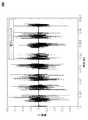
上述のように、バースト的なノイズは、併存している、又は近くに存在する無線エネルギー源によりもたらされることが多い。異なるソース毎に、異なるバースト的な特徴の強度を有する。例えば、近くに存在するブルートゥース(登録商標)無線は、10%ないし40%のデューティサイクルで妨害を与える。従来の電子レンジは、10%のデューティサイクルで妨害を与える。インバータタイプの電子レンジは、50%ないし60%のデューティサイクルで妨害を与える(これらは、通信トラフィックパターンに依存する)。 As mentioned above, bursty noise is often caused by coexisting or nearby wireless energy sources. Different sources have different bursty feature strengths. For example, nearby Bluetooth® radios can interfere with a 10% to 40% duty cycle. Conventional microwave ovens interfere with a 10% duty cycle. Inverter-type microwave ovens cause interference with a duty cycle of 50% to 60% (these depend on the communication traffic pattern).
図1Aないし図1Cは、異なる複数のソースからの妨害を示している。例えば、図1Aのグラフ100は、電子レンジからの妨害を示している。図1Bのグラフ110は、(SCOリンクによる音声トラフィックのための)ブルートゥース無線の妨害を示している。 1A-1C show the interference from different sources. For example, the
図1Cのグラフ120は、(5メガビット/秒(Mbps)アップリンクトラフィックの)WiFi(IEEE802.11)無線からの妨害を示している。 The
上述のように、リンク適応技術は、妨害及びノイズに対処するために採用される技術である。従来のリンク適応技術は、パケットが正しく受信されない場合、データ転送速度を低下させる傾向がある。このような従来技術は、バースト的でないノイズに適している。例えば、付加ホワイトガウスノイズが挙げられる。この理由は、これらのノイズが常に発生していると仮定されているからである。したがって、このような、常に発生するノイズに対して、(低いビットエラー確率を提供することによって)データ転送速度を低下させることは効果的である。 As described above, link adaptation techniques are techniques that are employed to combat jamming and noise. Conventional link adaptation techniques tend to reduce the data rate if packets are not received correctly. Such prior art is suitable for non-burst noise. For example, additional white Gaussian noise can be mentioned. This is because it is assumed that these noises are always generated. Therefore, it is effective to reduce the data transfer rate (by providing a low bit error probability) against such constantly occurring noise.
しかしながら、通常の「現実の生活」の環境においては、バースト的なノイズ(たとえば、「オン」「オフ」の時間)が発生する。このようなバースト的なノイズによって、従来のレート適応技術は、効果的ではない。なぜなら、バースト的なノイズが存在する場合、データ転送速度/またはMCSを低下させることは、データ転送の時間(たとえば、WiFiパケット)を増加させるばかりでなく、バースト的なノイズに衝突するデータパケットの確率を増加させる。このため、WiFiのパフォーマンスは、結果的に低下してしまう。 However, in a normal “real life” environment, bursty noise (eg, “on” and “off” time) occurs. Due to such bursty noise, conventional rate adaptation techniques are not effective. Because in the presence of bursty noise, reducing the data rate / or MCS not only increases the data transfer time (eg, WiFi packets), but also reduces the data packets that collide with bursty noise. Increase probability. For this reason, the performance of WiFi is reduced as a result.
従来のアプローチとは異なり、実施例では、バースト的なノイズ環境に直面した場合には、データ転送速度を減少させることを控える。この結果、パケットの時間は増加しない。これは、好適に、バースト的なノイズ環境下におけるエラーフリーの通信の確率を増加させるのである。 Unlike conventional approaches, the embodiment refrains from reducing the data transfer rate when faced with a bursty noise environment. As a result, the packet time does not increase. This preferably increases the probability of error-free communication in a bursty noise environment.
図2は、例示的な動作環境200を示している。この環境において、第1のデバイス202は、無線で第2のデバイス204にデータ送信230を行う。しかしながら、この無線送信は、妨害によりエラーが発生する。たとえば、図2において、妨害しているデバイス206は、妨害送信232を発生させる。これは、データ送信230が正確にデバイス204によって受信されることを阻止する。 FIG. 2 illustrates an
このような妨害送信は、バースト的に発生する。たとえば、例示的な送信は、図1に示すような特徴を呈する。したがって、妨害しているデバイス206は、たとえば、電子レンジ、併存又は近隣の無線機(WiFi無線、ブルートゥース無線等)又はバースト的妨害のその他のソースが挙げられる。 Such jamming transmission occurs in a burst manner. For example, the exemplary transmission exhibits features as shown in FIG. Thus, the interfering
実施例において、デバイス202は、通信メディア(たとえば無線チャネル)が、現在バースト的ノイズの状態にあるか否か、又は、通信メディアが現在、実質的にバースト的なノイズが無い状態であるか否かを判断する、試験技術(probing technique)によって、バースト的な妨害を取り扱うことができる。このような判断に基づいて、デバイス202は、対応する通信技術を採用することができる。 In an embodiment,
実施例において、図2の環境は、無線ディスプレイ(WiDi)アプリケーションに関連する(なお、これらに限られるものではない)。デバイス202は、たとえばパーソナルコンピュータ(PC)、ノートブック又はラップトップコンピュータ、あるいは、その他の適切なデバイス等の、コンピューティングプラットフォームである。そして、デバイス204は、ディスプレイであってもよい。動作中において、デバイス202は、ディスプレイデータ(例えば、データ送信230)をデバイス204に送信する。このデータは、様々なディスプレイ、ビデオ、及び/又は画像符号化フォーマットにエンコードされる。受信すると、デバイス204は、受信したディスプレイデータをデコードし、表示する。 In an embodiment, the environment of FIG. 2 relates to (but is not limited to) wireless display (WiDi) applications.
デバイス202は、様々な要素を含み、これらは、ハードウエア、及び/又はソフトウエアのいかなる組み合わせによってもインプリメントされ得る。例えば、図2において、デバイス202は、WiDiモジュール210を含む。これは、無線ディスプレイデータ送信を生成する。このディスプレイデータは、デバイス202で動作している1つ以上のアプリケーション及び/又はプロセス212によって提供される。このようなアプリケーション/プロセスは、ハードウエア及び/又はソフトウエアのあらゆる組み合わせによって実行され得る。実施例として、図2において、デバイス202は、記憶媒体(例えばメモリ)216を含み、記憶媒体はこれらのアプリケーション及び/又はプロセスに関連する命令を格納する。また、図2において、デバイス202は、これらの命令を実行する1つ以上のプロセッサ(例えばマイクロプロセッサ)214を含む。
図2に示すように、デバイス204は、無線データを受信するためのWiDiモジュール220を含む。さらに、図2に示すように、このディスプレイデータをデコードロジック222、及びデコードされたディスプレイデータを視覚的に出力するための物理的ディスプレイディバイス224を含む。デバイス204の要素は、ハードウエア及び/又はソフトウエアのいかなる組み合わせによってインプリメントされてもよい。例えば、デバイス204は、記憶媒体(例えばメモリ)及び1つ以上のプロセッサを含むことができる。これらは、WiDiモジュール220及びデコードロジック222の機能を提供する命令を記憶し実行することができる。 As shown in FIG. 2,
WiDiモジュール210及び220は、様々な無線ネットワーク標準に従って動作することができる。例えば、これらのモジュールは、米国電気電子学会(IEEE)802.11標準(WiFi標準)の1つ以上に従って、動作することができる。なお、実施例は、これらの標準に限定されるものではない。更に、実施例は、無線ディスプレイの利用に限定されるものではない。 WiDi modules 210 and 220 can operate according to various wireless network standards. For example, these modules can operate according to one or more of the Institute of Electrical and Electronics Engineers (IEEE) 802.11 standard (WiFi standard). In addition, an Example is not limited to these standards. Furthermore, embodiments are not limited to the use of wireless displays.
従来のIEEE802.11のレート適応メカニズムについて以下に詳述する。このメカニズムに従って、無線通信デバイスは、データ転送速度を選択するドライバを用いることができる。この動的な選択は、近いデータ転送速度のうちで、長期間の推定されたスループットの最適なものを提供することを目的としている。このデバイスは、最初のデータ転送速度として、選択されたデータ転送速度を用いる。この最初のデータ転送速度の決定プロセスは、信号及びノイズの遅い変化をトラッキングする。この例としては、アクセスポイントから離れたところで歩いていることによる変化が挙げられる。 A conventional IEEE 802.11 rate adaptation mechanism will be described in detail below. According to this mechanism, the wireless communication device can use a driver that selects the data transfer rate. This dynamic selection is aimed at providing an optimal long-term estimated throughput of close data rates. This device uses the selected data transfer rate as the initial data transfer rate. This initial data rate determination process tracks slow changes in signal and noise. An example of this is a change caused by walking away from the access point.
この選択に基づいて、デバイスは転送速度テーブル(rate table)を作成する。例えば、典型的な転送速度テーブルとしては、段階的に減少するようにアレンジされた16個の転送速度を含むテーブルが挙げられる。この転送速度テーブルによって、デバイスは、(例えば、マイクロコードの実行によって)短期間の転送速度の調整を実行できる。 Based on this selection, the device creates a transfer rate table. For example, a typical transfer rate table includes a table including 16 transfer rates arranged to decrease in stages. This transfer rate table allows the device to perform short-term transfer rate adjustments (eg, by executing microcode).
このような短期間の転送速度の調整は、(例えば、弱い信号又は妨害ノイズに基づく衝突による)パケットの損失が発生した場合になされる。例えば、パケット損失が発生した場合(例えば、受信側デバイスから対応するACKを受信しない場合)、デバイスは、テーブルにおける、より遅い転送速度によって自動的にパケットを再送する。更にパケット損失がある場合には、転送速度テーブルにおける、次の、より遅い転送速度によって、後の送信を行う。パケット送信が成功した場合、次の送信は、最初のデータ転送速度を採用するようにする。 Such short-term transfer rate adjustments are made when packet loss occurs (eg, due to collisions based on weak signals or jamming noise). For example, when packet loss occurs (eg, when no corresponding ACK is received from the receiving device), the device automatically resends the packet at a slower transfer rate in the table. If there is further packet loss, the subsequent transmission is performed at the next slower transfer rate in the transfer rate table. If the packet transmission is successful, the next transmission will adopt the first data rate.
したがって、データ転送速度を低下させることによって、この技術は、AWGN(付加ホワイトガウスノイズ)チャネルにおけるパケットの成功確率を向上させる。しかしながら、この短期間の調整技術は、パケットの期間より長いものとしてしまう。上述のように、このような期間の増加は、バースト的なノイズの環境において成功裏にパケットを送信するできる確率を低下させることとなる。 Therefore, by reducing the data transfer rate, this technique improves the probability of packet success in the AWGN (Additional White Gaussian Noise) channel. However, this short-term adjustment technique would be longer than the packet period. As described above, such an increase in period reduces the probability of successfully transmitting a packet in a bursty noise environment.
このようなアプローチに加えて、実施例は、無線チャネル(無線メディア)の試験(probe)を行う技術を採用する。このような技術は、好適にバースト的なノイズの環境を管理し、しかも従来の通信速度調整技術のようにパケットの期間を過度に増加させることがない。 In addition to such an approach, the embodiment employs a technique for testing a wireless channel (wireless media). Such a technique preferably manages a bursty noise environment and does not excessively increase the packet period as in the conventional communication speed adjustment technique.
このような技術では、送信デバイスは、無線試験パケットを宛先デバイスに送信する。この試験パケットが受信デバイスに正しく受信された場合、送信デバイスは、1つ以上のデータパケットを受信デバイスに送信する。この送信デバイスは、このデータパケットが所定の数になるまで、1つ1つ、これらのデータパケットを送信することができる。このロスが発生した場合、送信デバイスは、他の試験パケットを受信デバイスに送る。事実、送信デバイスは、正しく受信するまで、この試験パケットを何回も送ることができる。 In such a technique, the transmitting device transmits a wireless test packet to the destination device. If the test packet is correctly received by the receiving device, the transmitting device transmits one or more data packets to the receiving device. The transmitting device can transmit these data packets one by one until the data packets reach a predetermined number. When this loss occurs, the transmitting device sends another test packet to the receiving device. In fact, the transmitting device can send this test packet many times until it receives it correctly.
したがって、実施例は、バーストノイズを検出するために試験パケットを採用する。例えば、この試験パケットは、現在、「バースト妨害の期間」(「on period」とも称す)が存在するか、又は、「バースト妨害期間外」(「off period」とも称す)を検出することができる。)この検出に基づいて、送信デバイスは、「オフ期間」の間にデータを送信し、「オン期間」の間は、バックオフ(back off:送信を延期)する。オフ期間において、データ転送速度は、従来のIEEE802.11技術に従って決定された最初のデータ転送速度である(この点については、既に述べた)。試験パケットの送信が成功することは、データパケットの送信が成功する可能性が高いことを示すが、それよりも高くない場合は、そうでないような試験パケットのデータ転送速度を選択することが望ましい。例えば、試験パケットは、最初のデータ転送速度よりも少しだけ高いデータ転送速度であることが望ましく、これによって、短いパケット長となる。したがって、試験パケットのデータ転送速度は、レート適応技術に従って、(例えば、このような適応技術の最初のデータ転送速度に基づいて)選択され得る。 Thus, the embodiment employs a test packet to detect burst noise. For example, this test packet can currently detect “burst jamming period” (also referred to as “on period”) or “outside burst jamming period” (also referred to as “off period”). . Based on this detection, the transmitting device transmits data during the “off period” and back off (delays transmission) during the “on period”. In the off period, the data transfer rate is the initial data transfer rate determined in accordance with conventional IEEE 802.11 technology (this has already been described). Successful transmission of the test packet indicates that the transmission of the data packet is likely to be successful, but if not, it is desirable to select a data rate for the test packet that is not so . For example, the test packet desirably has a data transfer rate that is slightly higher than the initial data transfer rate, which results in a shorter packet length. Thus, the data rate of the test packet can be selected according to a rate adaptation technique (eg, based on the initial data rate of such an adaptation technique).
実施例において、送信デバイスは、受信デバイスが1つ以上の試験パケットの受信に失敗した場合、「オン期間」であることを検出する。これに対して、送信デバイスが、受信デバイスが試験パケットの受信に成功した場合、「オフ期間」を検出する。実施例において、受信デバイスは、肯定応答(ACK)を送信デバイスに送信することを介して、受信が成功したことを示す。 In an embodiment, the transmitting device detects an “on period” if the receiving device fails to receive one or more test packets. On the other hand, when the receiving device has successfully received the test packet, the transmitting device detects the “off period”. In an embodiment, the receiving device indicates successful reception through sending an acknowledgment (ACK) to the transmitting device.
追加的な通信オーバーヘッド(すなわち、データパケットに加えて、試験パケットを採用することによるオーバーヘッド)が発生することとなるが、この技術は、衝突の発生を好適に減少させる。更に、この技術によって、減少方向のデータ転送速度の調整は、好適に回避することができる。この結果、追加的なオーバーヘッドが発生するにもかかわらず、より良いパフォーマンスが達成される。 Although additional communication overhead (i.e., overhead due to employing test packets in addition to data packets) will occur, this technique suitably reduces the occurrence of collisions. Furthermore, adjustment of the data transfer rate in the decreasing direction can be preferably avoided by this technique. This results in better performance despite additional overhead.
このような技術によって、パケット(例えば、試験パケット又はデータパケット)の受信が成功したことは、送信デバイスが受信デバイスから対応する肯定応答(ACK)を受信することによって示される。逆に、受信デバイスからの対応する肯定応答の受信を送信デバイスが失敗することによって、パケットロスが示される。 With such a technique, successful reception of a packet (eg, test packet or data packet) is indicated by the transmitting device receiving a corresponding acknowledgment (ACK) from the receiving device. Conversely, a packet loss is indicated by the sending device failing to receive a corresponding acknowledgment from the receiving device.
図3は、例示的なフローチャート300を示している。これは、本明細書の1つ以上の実施例によって実行される動作の例を示す。まず、このフローは図2の構成に基づいている。しかしながら、実施例は、これに限定されるものではない。また、図3は、特定のシーケンスを示すが、他のシーケンスが採用されても良いことは言うまでもない。更に、記載された動作は、パラレル及び/又はシーケンシャルの様々な組み合わせで実行され得る。 FIG. 3 shows an
図3のフローチャートは、ソースデバイス及び宛先デバイスに関連して描かれている。図2において、ソースデバイスは、デバイス202であり、宛先デバイスは、デバイス204である。しかしながら、実施例はこの例に限定されるものではない。 The flowchart of FIG. 3 is drawn in relation to a source device and a destination device. In FIG. 2, the source device is the
ブロック302で、ソースデバイスは、無線通信メディア(例えば、1つ以上のIEEE802.11チャネル)を試験する。そして、チャネルのノイズ状態を判断する。上述したように、これは、ソースデバイスが、1つ以上の試験パケットを送信することに関連する。試験パケットの例としては、送信要求(RTS:ready-to-send)パケット及び専用の(dedicated)試験パケットが挙げられる(なお、これらに限定されるものではない)。そして、ソースデバイスは、これらの試験パケットに対する宛先デバイスからの応答を待つ。この応答は、送信可(CTS:clear-to-send)パケット、専用応答パケット、及び/又はその他の適切な送信であってもよい。 At
ブロック304で、ソースデバイスは、無線通信メディアが(clear:バーストノイズ、又はバースト的な状態でない)空き、であるか否かを判断する。その場合には、処理は306に進む。 At
ブロック306で、ソースデバイスは、1つ以上のデータパケットを宛先デバイスに送信する。実施例において、このデータ転送は、レート適応技術(例えば、上述の従来のIEEE802.11のレート適応メカニズム)を採用しない。データパケットが成功裏に宛先デバイスによって受信された場合、宛先デバイスは、肯定応答(ACK)パケットをソースデバイスに送信する。このようにして、ソースデバイスは、送信されたデータパケットの受信の各々の肯定応答を待つ。 At block 306, the source device transmits one or more data packets to the destination device. In an embodiment, this data transfer does not employ rate adaptation techniques (eg, the conventional IEEE 802.11 rate adaptation mechanism described above). If the data packet is successfully received by the destination device, the destination device sends an acknowledgment (ACK) packet to the source device. In this way, the source device waits for each acknowledgment of receipt of the transmitted data packet.
ブロック308に示すように、ソースデバイスは、試験状態が存在するかを判断する。試験状態の例としては、宛先デバイスからのデータパケットの肯定応答の受信の失敗が挙げられる。例えば、肯定応答の無いデータパケットの数が所定の閾値に達した場合には、ソースデバイスは、試験状態が存在すると判断する。 As shown in
図3に示すように、試験状態が存在する場合、処理は、302に戻る。そして、無線メディアに対して、更に試験が行われる。したがって、ソースデバイスは、データパケットの送信を中断し、後のデータパケット送信の再開のために、通信メディアの試験を再度行う。 As shown in FIG. 3, if a test condition exists, the process returns to 302. Further tests are performed on the wireless media. Thus, the source device interrupts the transmission of the data packet and retests the communication media to resume the subsequent data packet transmission.
上述のように、コントロールパケットが、メディアを試験するために採用される。 As described above, control packets are employed to test the media.
様々なタイプの試験パケットが採用され得る。例えば、実施例において、RTSパケットを試験パケットとして採用することができる。この場合、対応する肯定応答パケットは、CTSパケットであってもよい。あるいは、又は追加的に、実施例において、Nullデータパケットを試験パケットとして採用してもよい。あるいは/これに加えて、ACKパケットを対応する肯定応答パケットとして採用してもよい。更に、専用の試験コントロールパケットを採用してもよい。この点については、図4及び図5を用いて説明する。なお、実施例は、これらの例示に限定されるものではない。 Various types of test packets can be employed. For example, in the embodiment, an RTS packet can be adopted as a test packet. In this case, the corresponding acknowledgment packet may be a CTS packet. Alternatively or additionally, Null data packets may be employed as test packets in embodiments. Alternatively / additionally, an ACK packet may be employed as a corresponding acknowledgment packet. Furthermore, a dedicated test control packet may be employed. This point will be described with reference to FIGS. In addition, an Example is not limited to these illustrations.
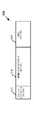
図4及び図5は、例示的コントロールパケットのダイヤグラムを示している。図4は、例示的な専用試験パケット400を示す。図5は、例示的な専用試験応答パケット500を示す。 4 and 5 show diagrams of exemplary control packets. FIG. 4 shows an exemplary
図4に示されるように、試験パケット400は、フレームコントロールフィールド402と、受信STAアドレスフィールド404と、送信されたSTAアドレスフィールド406と、CRCフィールド408とを含む。更に、図4は、各フィールドに対して例示的にバイトでサイズを示している。フレームコントロールフィールド402は、パケット400が試験パケットであることを識別するためのものである。受信STAアドレスフィールド404は、宛先の受信デバイスを示す。送信されたSTAアドレスフィールド406は、送信デバイスを示す。CRCフィールド408は、パケット400におけるエラーの検出を可能とさせる。 As shown in FIG. 4, the
図5において、試験応答パケット500は、フレーム制御フィールド502と、受信されたSTAアドレスフィールド504と、CRCフィールド502とを含む。フレーム制御フィールド502は、パケット500が、試験応答パケットであることを識別させるためのものである。受信されたSTAアドレスフィールド504は、宛先の受信デバイスを示す。CRCフィールド506は、パケット500におけるエラーの検出を可能とさせる。 In FIG. 5, the
したがって、実施例においては、従来の受信要求/送信可(RTS/CTS)プロテクション方式に対して好適な、試験パケット技術を採用することができる。この従来のRTS/CTSプロテクション方式は、送信デバイス(例えば、WiDiに対しては、パーソナルコンピュータの内部のWiFiモジュール)がRTSパケットを送信することを採用している。RTSパケットの受信に応答して、受信デバイス(例えば、ワイヤレスディスプレイのWiDiアダプタ)がCTSパケットを送信する。 Therefore, in the embodiment, a test packet technique suitable for the conventional reception request / transmission enabled (RTS / CTS) protection scheme can be adopted. This conventional RTS / CTS protection method employs that a transmitting device (for example, a WiFi module inside a personal computer for WiDi) transmits an RTS packet. In response to receiving the RTS packet, the receiving device (eg, the WiDi adapter of the wireless display) transmits the CTS packet.
このRTS/CTSプロテクションスキームにおいて、RTS及びCTSフレームの交換が成功裏に行われた場合、送信デバイスは、所定の時間期間(SIFS間隔:short Interframe spacing interval)だけ待った後、データパケットを送信することができる。しかしながら、所定の時間間隔内で、送信デバイスがCTSパケットを受信しない場合、その送信デバイスは、バックオフタイムウィンドウの後に、RTSパケットを再送信する。 In this RTS / CTS protection scheme, if the exchange of RTS and CTS frames is successful, the transmitting device waits for a predetermined time period (SIFS interval: short Interframe spacing interval) and then transmits the data packet. Can do. However, if the transmitting device does not receive the CTS packet within the predetermined time interval, the transmitting device retransmits the RTS packet after the backoff time window.
この従来のRTS/CTSプロテクション方式の例を、図6A及び図6Bに示す。特に、図6Aは、RTS/CTS交換600の例(ブロックAとしても表記されている)を示している。この交換において、ソースデバイス610は、RTSパケット602を、宛先デバイス620に分散されたフレーム間スペース期間(DIFS:Distributed Interframe Space)の後に送信する。 An example of this conventional RTS / CTS protection scheme is shown in FIGS. 6A and 6B. In particular, FIG. 6A shows an example of an RTS / CTS exchange 600 (also denoted as block A). In this exchange, the
これに対して、宛先デバイス620は、SIFS(short Interframe space)期間の後、CTSパケット604をソースデバイス610に送信することにより応答する。 In response, the
CTSパケット604を受信すると、ソースデバイス610は、SIFS期間だけ待ち、データパケット606を宛先デバイス620に送信する。このデータパケットを受信すると、宛先デバイス620は、肯定応答(ACK)パケット608を送信する。ACK608の受信の後、ソースデバイス610は、DIFS期間、及びバックオフ(BO)時間間隔だけ待つ。 Upon receiving the
図6Bは、「ブロックA」交換600の例を示している。特に、図6Bは、連続的に実行される二つの交換(600a及び600b)を示している。更に、図6Bは、これらの交換が、バースト的ノイズがオフの期間650の間に実行されることを示している。この期間は、バースト的なノイズ652a及び652bの間に位置している。 FIG. 6B shows an example of a “Block A”
図6A及び図6Bの従来のRTS/CTSプロテクション方式は、特定の状況の時には、利用価値がある。例えば、この従来の方式は、混雑している領域(例えば、WLANネットワークがオーバーラップしている領域)において利用価値がある。この従来の方式によって、同一の物理的チャネルに存在する各ステーションは、ネットワークアロケーションベクトル(NAV)を受信する。そして、(異なるネットワークに対する構成された状態であったとしても)それらのメディアアクセスを適切に遅らせる。更に、この従来方式は、よく知られた非常時ノード(hidden node)及び表示ノード(exposed node)の問題を解決するのに利用できる。 The conventional RTS / CTS protection scheme of FIGS. 6A and 6B has utility value in certain situations. For example, this conventional method is useful in a congested area (for example, an area where WLAN networks overlap). With this conventional scheme, each station residing on the same physical channel receives a network allocation vector (NAV). And appropriately delay their media access (even if configured for different networks). Furthermore, this conventional scheme can be used to solve the well-known problems of hidden nodes and exposed nodes.
しかしながら、バースト的ノイズの存在する環境を取り扱うために、従来のRTS/CTSプロテクション方式を用いることに対する欠点も存在する。例えば、データパケットの各々をRTS及びCTSパケットでラッピングすることによって、この方式は、過度の通信バンド幅を消費してしまうことになる。この結果、全体的なスループットが、許容できないレベルにまで落ちてしまう。 However, there are also drawbacks to using conventional RTS / CTS protection schemes to handle environments with bursty noise. For example, by wrapping each of the data packets with RTS and CTS packets, this scheme consumes excessive communication bandwidth. As a result, the overall throughput falls to an unacceptable level.
ここに説明するように、実施例では、試験パケットがバースト的ノイズの「オン期間」又は「オフ期間」が存在するか否かを検出するために用いられる。試験パケットは、様々な態様でインプリメントされ得る。例えば、RTS/CTSパケット、及び専用の試験パケットが採用され得る。しかしながら、送信及び受信デバイスが、同じ試験パケットの定義を採用し、かつ、それらのパケットがメディア(チャネル)の状態を通信できる限り、いかなるパケットの形式が利用されてもよい。 As described herein, in an embodiment, a test packet is used to detect whether an “on period” or “off period” of bursty noise exists. The test packet can be implemented in various ways. For example, RTS / CTS packets and dedicated test packets can be employed. However, any packet format may be utilized as long as the transmitting and receiving devices adopt the same test packet definition and can communicate the state of the media (channel).
試験メカニズムの例が、図7A及び図9に示されている。 Examples of test mechanisms are shown in FIGS. 7A and 9.
図7A及び図7Bは、試験パケットの交換の例を示している。この交換は、「ブロックB」としても記載されている。特に、図7Aにおいて、試験パケットは、RTS/CTSパケットでインプリメントされている。これに対して、図7Bは、専用の試験パケットの採用が示されている。 7A and 7B show examples of test packet exchange. This exchange is also described as “Block B”. In particular, in FIG. 7A, the test packet is implemented with an RTS / CTS packet. On the other hand, FIG. 7B shows the adoption of a dedicated test packet.
例えば、図7Aにおいて、ソースデバイス710は(DIFSインターバルの後)RTSパケット702を、試験パケットとして、宛先デバイス720に送信する。このRTSパケットを受信すると、宛先デバイス720は、(SIFSインターバルの後)CTSパケット704をソースデバイス710に送信する。図7Aに示すように、SIFSインターバルは、CTSパケット704の後に続く。図7Bは、図7Aと同じ交換を採用している。しかしながら、図7Bにおいては、専用の試験パケット706及び専用の試験応答パケット708が採用されている。これらのパケットは、図4及び図5に従ってフォーマットされ得る。なお、実施例は、これに限定されるものではない。 For example, in FIG. 7A, the
図8は、ソースデバイスと、本明細書で説明した試験の技術を用いた、宛先デバイスとの間での例示的な交換を示している。特に、図8において、ノイズオフ期間で、「ブロックB」の交換が実行されている(ブロックB(#1)として示す)。図7A及び図7Bに関連して既に述べたように、ブロックBの交換においては、ソースデバイスが試験パケットを送り、そして、宛先デバイスが対応する試験レスポンスを応答する。 FIG. 8 illustrates an exemplary exchange between a source device and a destination device using the testing techniques described herein. In particular, in FIG. 8, “Block B” is exchanged during the noise-off period (shown as Block B (# 1)). As already described in connection with FIGS. 7A and 7B, in the block B exchange, the source device sends a test packet and the destination device responds with a corresponding test response.
ブロックBの交換に続いて、図8においては、第1のデータパケット(データ(#1)として示す)がソースデバイスから宛先デバイスに送信される。このデータパケットにSIFSインターバルと、宛先デバイスからソースデバイスへのACK送信と、DIFSインターバルと、バックオフ(BO)インターバルとが続く。図8において、第2のパケット(データ(#2)として示す)についても実行される。同様に第3のデータパケット(データ(#3)として示す)についても同様である。 Following the exchange of block B, in FIG. 8, a first data packet (shown as data (# 1)) is transmitted from the source device to the destination device. This data packet is followed by a SIFS interval, an ACK transmission from the destination device to the source device, a DIFS interval, and a backoff (BO) interval. In FIG. 8, the second packet (shown as data (# 2)) is also executed. The same applies to the third data packet (shown as data (# 3)).
図8では、このようなデータ送信は、ノイズオフ期間820の間に行われる。これは、ノイズオン期間822a及び822bの間に存在する。更に、ノイズオン期間822bが開始されると、ソースデバイスは、宛先デバイスからデータパケットの肯定応答を受信しなくなる。このため、ソースデバイスは、試験を再開する。例えば、図8において、ブロックBの交換(「ブロックB(#2)」として示す)は、その後のノイズオフ期間824で行われている。ここで示されているように、この交換の成功は、バーストノイズオフ期間として示されている。そして、ここに記載されている技術に基づくデータ送信が実行される。 In FIG. 8, such data transmission is performed during the noise off
図9は、ソースデバイス902と、宛先デバイス904との間の更なる交換のフローが記載されている。この交換は、本明細書に開示されている試験(probing)の技術が採用されている。図9に示すように、ノイズオン期間906において、ソースデバイス902は、データパケット910を宛先デバイス904に送信する。しかしながら、ノイズのために、ソースデバイス902は、対応する肯定応答を宛先デバイス904から受信しない。 FIG. 9 describes a further exchange flow between the
このため、ソースデバイス902は、メディアの試験を開始する。より具体的には、ソースデバイス902は、RTSパケット912、914、916、及び918を宛先デバイスに送信する。図9に示すように、RTSパケット918は、ノイズオフ期間907において送信される。したがって、ソースデバイス902は、対応する試験応答をCTSパケット920の形で受信する。 Therefore, the
CTSパケット920を受信することに基づいて、ソースデバイス902は、データパケットのシーケンスを宛先デバイス904に送信する。より具体的には、図9において、ソースデバイス902は、データパケット922、926、930、及び940を送信する。これらの各々のデータパケットに対して、ソースデバイスは、肯定応答(ACK)を宛先デバイス904から受信する。これらのACKは、図9において、ACK924、928、932、及び936として示されている。 Based on receiving the
図9において、データパケット940に対して、ソースデバイス902は、対応する肯定応答を宛先デバイス904から受信しない。したがって、ソースデバイス902は、メディアに対して試験を再度開始する。例えば、図9のソースデバイス902は、(試験パケットとして)RTSパケット942、944、及び946を宛先デバイス904に送信する。 In FIG. 9, for
期間908におけるノイズの後、ソースデバイス902は、試験応答(CTSパケット948)を宛先デバイス904から受信する。このようにして、ソースデバイス902は、データパケット950を宛先デバイス904に送信することによって、データ送信を再開する。これに応答して、ソースデバイス902は、対応するACK952を宛先デバイス904から受信する。 After noise in period 908,
したがって、図9に示すように、無線通信デバイスは、試験パケットを用いることによって、無線チャネル(無線メディア)を試験することができる。この試験から、デバイスは、無線メディアが現在バースト的な妨害を受けているか否かを検出することができる。換言すれば、デバイスは、バースト的妨害の「オン期間」又は「オフ期間」か否かを検出することができる。 Therefore, as shown in FIG. 9, the wireless communication device can test the wireless channel (wireless media) by using the test packet. From this test, the device can detect whether the wireless media is currently experiencing bursty interference. In other words, the device can detect whether it is an “on period” or “off period” of bursty disturbance.
無線デバイスが「オフ期間」を検出した場合、そのデバイスは、データパケットの送信を開始又は再開することができる。デバイスは、データパケットを1つずつ送信する。これは、特定の回数を超える再送信がなされるまで続く。この状況の場合には、バースト的妨害の「オン期間」が存在していることを示す。 If a wireless device detects an “off period”, it can start or resume transmission of data packets. The device transmits data packets one by one. This continues until more than a certain number of retransmissions are made. In this situation, it indicates that an “on period” of bursty disturbance exists.
実施例において、試験パケット(例えば、RTSパケット)は、特定の時間間隔において通信デバイスを占有(reserve)する。しかしながら、実施例では、予測される試験応答パケット(例えばCTSパケット)を受信する期間よりも、メディアをより長い時間占有することは避けることができる。この理由は、目的の受信デバイスは混雑している(Jammed)が、他のデバイスは、この弊害を受けず、かつメディアを使用することもできるからである。 In an embodiment, a test packet (eg, an RTS packet) occupies a communication device at a specific time interval. However, in an embodiment, it can be avoided to occupy the media for a longer time than the period of receiving an expected test response packet (eg, a CTS packet). This is because the target receiving device is congested (Jammed), but other devices are not affected by this problem and can use the media.
例えば、通信メディアを占有することを維持することによって、他のデバイスは、メディアをリリースするための(contention-free-end)が送信されるまで、そのメディアを利用することができない。したがって、実施例において、試験パケット(例えば、RTSパケット)は、正確にCTSとソースデバイスのデータパケットのプリアンブルの間、メディアを占有する。 For example, by maintaining occupation of the communication media, other devices cannot use the media until a contention-free-end is sent. Thus, in an embodiment, a test packet (eg, an RTS packet) occupies the media exactly during the preamble of the CTS and the source device data packet.
図10は、例示的なフローチャート1000を示している。これは、1つ以上の実施例によって実行される動作の例を示している。図2の環境において、この動作が行われてもよい。なお、実施例は、これに限定されるものではない。図10は、特定のシーケンスを示しているが、他のシーケンスが採用されてもよい。加えて、示されている動作は、同時的、及び/又は時系列的に様々に実行されてもよい。 FIG. 10 shows an
図10のフローチャートは、ソースデバイス及び宛先デバイスに関して記載されている。図2に示されたように、ソースデバイスはデバイス202であり、宛先デバイスはデバイス204である。なお、実施例はこれらに限定されるものではない。 The flowchart of FIG. 10 is described with respect to the source device and the destination device. As shown in FIG. 2, the source device is
ブロック1002で、ソースデバイスは、試験パケットを宛先デバイスに送信する。これに対して、ソースデバイスは、試験パケットの肯定応答が、宛先デバイスから受信されたか否かを判断する(ブロック1004)。もし、そうであれば、動作はブロック1012に進む。それ以外の場合には、動作はブロック1006に進む。 At
ブロック1006で、試験パケットの再送信の回数が、試験再送信閾値Nよりも、小さいか否かを判断する。そうであれば、動作はブロック1008に移る。それ以外の場合には、ブロック1010に進む。例示的に、図10において、閾値Nは15である。なお、他のNの値が採用されてもよい。 At
ブロック1008で、ソースデバイスは、試験パケットを再送信する。図10では、この再送信の後、動作はブロック104に戻る。したがって、この状態で、ソースデバイスは、試験パケットの肯定応答が受信されたか否かを判断する。 At
上述のように、ブロック1010は、試験パケットの再送信が閾値Nに達した場合に実行される。図10のブロック1010において、ソースデバイスは、従来のデータ送信プロトコルを採用する。より具体的には、ソースデバイスは、データを送信し、従来のIEEE802.11技術に従って(肯定応答が受信されたかに基づいて)短期間レート調整(short term rate adjustment)を採用する。図10に示すように、動作は、(例えば、パケット送信の成功又は所定の時間後に)ブロック1010からブロック1002に戻る
上述のように、ブロック1012は、ソースデバイスが、試験パケットの肯定応答が受信されたと判断した場合(ブロック1004)に、実行される。このブロックにおいて、ソースデバイスは、無線で、宛先デバイスにデータパケットを送信する。As described above,
この後、ブロック1014で、ソースデバイスは、宛先デバイスからデータパケットの肯定応答が受信されたか否かを判断する。その場合には、動作は、ブロック1012に戻る。ここで、ソースデバイスは更なるデータパケットを宛先デバイスに送信してもよい。 Thereafter, at
しかしながら、ソースデバイスが、データパケットの肯定応答を受信しない場合、動作はブロック1014から1016に進む。ブロック1016で、ソースデバイスは、データパケットの再送信が、データ送信閾値Kよりも小さい回数、繰り返されているか否かを判断する。この場合には、ブロック1018に進む。 However, if the source device does not receive an acknowledgment of the data packet, operation proceeds from
これ以外の場合には、動作はブロック1002に戻る。例示的目的のため、図10において、閾値Kの値は3である。なお、Kの値としてその他の値が採用されてもよい。 Otherwise, operation returns to block 1002. For illustrative purposes, in FIG. Other values may be adopted as the value of K.
図10に示すように、ソースデバイスは、ブロック1018で、データパケットを再送信する。 As shown in FIG. 10, the source device retransmits the data packet at
この後、動作はブロック1014に進む。 Thereafter, operation proceeds to block 1014.
図10においては、実施例は、既存のレート適応アルゴリズムを補足する技術を提供する。このような既存のアルゴリズムは、信号強度及びノイズの遅い変化に適合する場合に適切であるが、実施例におけるこの新たな技術は、バースト的なノイズを回避する
したがって、図10のフローは、基本的に2つのフローを含んでいると解釈できる。第1のループは、ブロック1002、1004、1006、1010、及び1002に戻るものである。このループは、従来のレート適応方式に該当する。したがって、(ブロック1006の)閾値Nが0になる場合、従来のレート適応技術が行う非常にルーズなパフォーマンスとなる。しかも、このフローにおいて、この従来の技術は、パケットの成功の統計に基づいて、一時的に最良の初期データ通信速度で採用される。In FIG. 10, the embodiment provides a technique that complements existing rate adaptation algorithms. Such an existing algorithm is suitable when adapting to slow changes in signal strength and noise, but this new technique in the embodiment avoids bursty noise. Therefore, the flow of FIG. Can be interpreted as including two flows. The first loop returns to
第2のループは、ブロック1012、1014、1016、及び1018のブロックに沿って進む。この、レート適応によらない技術は、ブロック1010で、レート適応技術に従って選択された初期設定の(に基づく)データ転送速度を採用するものである。上述のように、ブロック1010は、バースト的ノイズオフ状態の間に実行される。ブロック1010は、試験の転送速度での送信の成功がデータパケットの成功する転送確率が高いことを示し、かつこれよりも過剰な速度でないように、この最初のデータ転送速度を決定する。 The second loop proceeds along
図11のグラフ1100は、バーストノイズのデューティサイクルの範囲に亘って、3つの異なる送信技術のパフォーマンス特徴をシミュレートしたものである。より具体的には、グラフ1100において、カーブ1102は、既存のWiFiレート適応技術を採用した(試験の技術又はRTS/CTSプロテクションを採用しない)通信に対するスループットの特徴を示している。カーブ1104は、従来のRTS/CTSプロテクション方式を採用した通信のスループットの特徴を示している。そして、カーブ1106は、図10と共に本明細書において説明した試験ベースの技術を採用した通信のスループットの特徴を示している。 The
このカーブのプロットにおいて、ノイズは、16.6ミリ秒の間継続するとしてシミュレートしている。図11に示すように、バースト的ノイズのデューティサイクルは、ノイズのオン及びオフの期間を決定するため、大きな影響を与える。 In the plot of this curve, the noise is simulated as lasting for 16.6 milliseconds. As shown in FIG. 11, the duty cycle of bursty noise has a great influence because it determines the on and off periods of noise.
カーブ1106のデータに対して、試験パケット及び試験応答パケットは、RTS及びCTSと同じ構造を採用している。これらのパケットは、物理的通信速度として、24Mbps(メガビット/秒)で送信される。採用されたコンテンションウィンドウは、最小で7、最高で31である(これらは、WiDiアプリケーションにおいて採用されている)。チャネル状態は、バースト的ノイズがオフのとき極めて良好であり、バースト的ノイズがオンのとき、極めて悪いと仮定している。 For the data of the
カーブ1102の既存のWiFiレート適応メカニズムにおいて、データ転送速度は、一度再送信が発生すると、自動的に低下する。このため、WiFiパケットはより長い送信期間を必要とする。図11に示すように、このメカニズムは、バースト的ノイズが長期間オンの場合、パフォーマンスが悪化する。 In the existing WiFi rate adaptation mechanism of
カーブ1104の従来のRTS/CTSプロテクションメカニズムは、共有無線チャネル/メディアの利用において、よりよいコントロールを提供する。そして、RF妨害からのコリジョンを減少させるが、オーバーヘッドを伴う。なぜなら、RTS/SCT交換は、各パケットで行われるからであり、バーストノイズがオフの期間においても行われるからである。このような、過剰なオーバーヘッドは、本明細書における試験技術とは対称的である。この場合、試験パケットの交換は、バーストノイズのオフの期間で、1回のみ発生する。 The conventional RTS / CTS protection mechanism of
図11に示すように、本明細書におけるこの試験技術(カーブ1106)は、他の技術によるスループットよりも、大きなスループットを提供することができる。例えば、カーブ1106は、定常的に、カーブ1104よりも35%ないし40%高い値を示す。しかも、バースト的ノイズのデューティサイクルが40%を超える場合、カーブ1106は、カーブ1102(既存のWiFiレート適応技術)に比較して非常に高いスループットを示す。 As shown in FIG. 11, this test technique (curve 1106) herein can provide greater throughput than the throughput of other techniques. For example, the
図12は、インプリメンテーション1200のブロック図を示している。これは、基地局(例えば、BS 120a−g)及び又はモバイルステーション(例えば、MS 104a−h)等のワイヤレスデバイスに含まれ得る。インプリメンテーション1200は、様々な要素を含む。例えば、図12で、インプリメンテーション1200は、複数のアンテナ1202a−c、トランシーバモジュール1204、ホストモジュール1206、及びコントロールモジュール1208を含む。これらの要素は、ハードウエア、ソフトウエア、又は、これらのいかなる組合せによってもインプリメントすることができる。 FIG. 12 shows a block diagram of an
アンテナ1202a−cは、リモートデバイスと無線信号を交換するために提供される。
3つのアンテナが示されているが、いかなる数(1つ以上)のアンテナが用いられてもよい。更に、実施例において、1つ以上の送信アンテナ、及び1つ以上の受信アンテナが用いられてもよい。このような、複数のアンテナの構成は、ビームを形成するように、及び/又は、複数の空間的ストリームをリモートデバイスに形成するよう採用されてもよい。 Although three antennas are shown, any number (one or more) of antennas may be used. Further, in embodiments, one or more transmit antennas and one or more receive antennas may be used. Such multiple antenna configurations may be employed to form a beam and / or to form multiple spatial streams at a remote device.
トランシーバモジュール1204は、他のデバイスとの情報の交換をするために提供される。したがって、トランシーバモジュール1204は、本明細書に記載されているように、(アンテナ1202a−cを介して)様々な伝送を送信しかつ受信する。この伝送は、試験パケット及びデータパケットを含むが、これらに限定されるものではない。 The
図12に示されるように、トランシーバモジュール1204は、送信部1210及び受信部1212とを有する。動作において、トランシーバモジュール1204は、アンテナ1202a−cと、他の要素との間の、インタフェースを提供する。例えば、ホストモジュール1206、及びコントロールモジュール1208である。例えば、送信部1210は、これらの要素からシンボルを受信する。そして、対応する信号を生成し、生成された信号はアンテナ1202a−cの1つ以上によって無線伝送される。これは、変調、増幅、及び/又はフィルタリングの動作を含むことができる。なお、他の動作が採用されてもよい。 As illustrated in FIG. 12, the
これに対して、受信部1212は、1つ以上のアンテナ1202a−cによって受信された信号を取得し、対応するシンボルを生成する。これに応じて、これらのシンボルは、ホストモジュール1206、及びコントロールモジュール1208等の要素に提供される。このシンボルの生成は、復調、増幅、及び/又はフィルタリング等の動作を含むが、これらに限定されるものではない。 On the other hand, the receiving
トランシーバモジュール1204によって生成され受信された信号は、様々な形態を取ることができる。例えば、これらの信号は、直交周波数分割多重(OFDM)方式に従って変調されてもよい。なお、例えばQPSK、BPSK、FSK、等の他の方式及びフォームが採用され得る。 The signal generated and received by the
この特徴を提供するために、送信部1210及び受信部1212は、各々様々なコンポーネントを含むことができる。例えば、変調器、復調器、増幅器、フィルタ、バッファ、アップコンバータ、及び/又はダウンコンバータ等が挙げられる。このようなコンポーネントは、ハードウエア(例えば、エレクトロニクス)、ソフトウエア、及びいかなるこれらの組合せをも含み得る。 In order to provide this feature, the
トランシーバモジュール1204及び他の要素の間で交換されるこのシンボルは、メッセージ又は1つ以上のプロトコル及び/又は1つ以上のユーザアプリケーションに関連する情報を含み得る。したがって、これらの要素は、これらのプロトコル及び/又はユーザアプリケーションに対応する動作を実行することができる。プロトコルの例示としては、様々なメディアアクセスコントロール、及びディスカバリプロトコルが含まれるが、これらに限定されるものではない。例示的なユーザアプリケーションとしては、電話(テレフォニー)、メッセージング、電子メール、ウェブブラウジング、コンテンツ(例えばビデオ及びオーディオ)配信/受信等が挙げられる。 This symbol exchanged between the
更に、信号を送信する際、トランシーバモジュール1204は、様々なアクセス技術を採用することができる。例えば、トランシーバモジュール1204は、デュプレクス技術、時分割デュプレクス(TDD)、周波数分割デュプレクス(FDD)等が挙げられる。なお、実施例は、これらの技術に限定されるものではない。 Further, when transmitting signals, the
実施例において、コントロールモジュール1208は、本明細書において記載された様々な動作を実行することができる。例えば、図12に示すように、コントロールモジュール1208は、状態判断モジュール1214、及び送信技術選択モジュール1216を含む。 In an embodiment, the
状態判断モジュール1214は、無線通信メディアの現在の状態を判断する。例えば、トランシーバモジュール1204によって送信された試験パケット、及びトランシーバモジュール1204によって受信された試験応答パケット(もし存在すれば)に基づいて、状態判断モジュール1214は、通信メディアが空き(クリア)であるか否かを判断する。 The
この判断に基づいて、送信技術選択モジュール1216は、データパケットを送信するための技術を選択する。本明細書に記載したように、この選択は、レート適応技術でない技術、あるいは、レート適応技術である。 Based on this determination, the transmission
更に、状態判断モジュール1214は、データ送信の状態をモニタリングすることができる。例えば、状態判断モジュール1214は、肯定応答データパケットをカウントし、トランシーバモジュール1204が、更なるデータパケット送信が行われる前に、通信メディアの試験を行わなければならないかを判断する。 Further, the
ホストモジュール1206は、トランシーバモジュール1204との間で、シンボルを交換する。これは、リモートデバイスと交換される無線信号に対応する。これらのシンボルは、1つ以上のプロトコル、及び/又は1つ以上のユーザアプリケーションに関連するメッセージ又は情報を形成する。したがって、ホストモジュール1206は、このようなプロトコル及び/又はユーザアプリケーションに対応する動作を実行する。プロトコルの例としては、様々なメディアアクセス、ネットワーク、伝送、及び/又はセッションレイヤプロトコルが含まれる。ユーザアプリケーションの例としては、電話、メッセージング、電子メール、ウェブブラウジング、コンテンツ(例えば、ビデオ及びオーディオ)配信/受信等が含まれる。 The
本明細書において記載されているように、様々な実施例は、ハードウエア、ソフトウエア、又はいかなるこれらの組合せを用いてもインプリメントすることができる。ハードウエア要素の例としては、プロセッサ、マイクロプロセッサ、回路、回路要素(例えば、トランジスタ、抵抗、コンデンサ、インダクタ等)、集積回路、特定アプリケーション用集積回路(ASIC)、プログラマブルロジックデバイス(PLD)、ディジタルシグナルプロセッサ(DSP)、フィールドプログラマブルゲートアレー(FPGA)、論理ゲート、抵抗、半導体デバイス、チップ、マイクロチップ、チップセット、等が含まれる。 As described herein, the various embodiments may be implemented using hardware, software, or any combination thereof. Examples of hardware elements include processors, microprocessors, circuits, circuit elements (eg, transistors, resistors, capacitors, inductors, etc.), integrated circuits, application specific integrated circuits (ASIC), programmable logic devices (PLD), digital Signal processors (DSPs), field programmable gate arrays (FPGAs), logic gates, resistors, semiconductor devices, chips, microchips, chip sets, etc. are included.
ソフトウエアの要素としては、ソフトエアコンポーネント、プログラム、アプリケーション、コンピュータプログラム、アプリケーションプログラム、システムプログラム、マシーンプログラム、オペレーティングシステムソフトウエア、ミドルウエア、ファームウエア、ソフトウエアモジュール、ルーチン、サブルー心、機能、方法、手順、ソフトウエアインタフェース、アプリケーションプログラムインタフェース(API)、命令セット、コンピューティングコード、コンピュータコード、コードセグメント、コンピュータコードセグメント、ワード、値、シンボル、その他いかなるこれらの組合せも含む。 Software elements include software components, programs, applications, computer programs, application programs, system programs, machine programs, operating system software, middleware, firmware, software modules, routines, sub-hearts, functions, methods , Procedures, software interfaces, application program interfaces (APIs), instruction sets, computing code, computer code, code segments, computer code segments, words, values, symbols, and any combination thereof.
ある実施例は、例えば機械読み取り可能な記憶媒体又は部品を用いて、インプリメントすることができる。記憶媒体は、命令又は命令のセットを記憶することができ、この命令が機械によって実行された時に、機械が、実施例に従った方法及び/又は動作を実行することができる。このような機械は、例えば、適切なプロセッシングプラットフォーム、コンピューティングプラットフォーム、コンピューティングデバイス、プロセッシングデバイス、コンピューティングシステム、プロセッシングシステム、コンピュータ、プロセッサ等が挙げられる。そして、これらは、ハードウエア及び/又はソフトウエアのいかなる適切な組合せによってもインプリメントすることができる。 Some embodiments may be implemented using, for example, machine-readable storage media or components. A storage medium may store instructions or a set of instructions, and when the instructions are executed by the machine, the machine may execute the methods and / or operations according to the embodiments. Such machines include, for example, suitable processing platforms, computing platforms, computing devices, processing devices, computing systems, processing systems, computers, processors, and the like. These can then be implemented by any suitable combination of hardware and / or software.
明細書に記載されているように、実施例は、記憶媒体、又は機械読み取り可能な製品を含むことができる。これらは、適切なタイプのメモリユニット、メモリデバイス、メモリ製品、メモリ媒体、記憶デバイス、記憶製品、記憶媒体及び/又は記憶ユニット、例えば、メモリ、取り出し可能、又は取り出し不可能な媒体、消去可能又は消去不可能な媒体、再書き込み可能媒体、デジタル又はアナログ媒体、ハードディスク、フロッピー(登録商標)ディスク、CD−ROM、CD−R、CD−RW、光ディスク、磁気媒体、磁気光媒体、取り出し可能メモリカード又はディスク、様々なタイプのDVD、テープ、カセット等が挙げられる。命令は、いかなる適切なタイプのコードであってもよい。例えば、ソースコード、コンパイルされたコード、インタープリットされたコード、実行可能コード、静的コード、動的コード、暗号化コード等が挙げられる。これらは、いかなる適切なハイレベル、ローレベル、オブジェクトオリエンテッド、ビジュアル、コンパイルされた、及び/又は、インタープリトされたプログラミング言語であってもよい。 As described in the specification, examples may include storage media or machine-readable products. These may be any suitable type of memory unit, memory device, memory product, memory medium, storage device, storage product, storage medium and / or storage unit, e.g. memory, removable or non-removable medium, erasable or Non-erasable medium, rewritable medium, digital or analog medium, hard disk, floppy disk, CD-ROM, CD-R, CD-RW, optical disk, magnetic medium, magneto-optical medium, removable memory card Or a disk, various types of DVD, a tape, a cassette, etc. are mentioned. The instructions may be any suitable type of code. For example, source code, compiled code, interpreted code, executable code, static code, dynamic code, encrypted code, and the like. These may be any suitable high-level, low-level, object-oriented, visual, compiled and / or interpreted programming language.
以上、様々な実施例を説明したが、これらは例示的なものであり、限定するためのものではない点に留意すべきである。 While various embodiments have been described above, it should be noted that these are exemplary and not limiting.
したがって、当業者は、本発明の精神及び発明の技術的範囲を逸脱しない範囲で、形式及び詳細について様々な変更が加えられてもよいことを認識すべきである。したがって、本発明の技術的範囲は、上述の例示的実施例によって限定されるものではなく、以下の請求項及びその均等物にのみによって、限定されるものである。 Accordingly, those skilled in the art should recognize that various changes in form and detail may be made without departing from the spirit of the invention and the technical scope of the invention. Accordingly, the scope of the invention is not limited by the above-described exemplary embodiments, but only by the following claims and their equivalents.
Claims (19)
Translated fromJapanese前記1つ以上の試験パケットの応答結果に基づいて、レート適応送信技術、及びレート適応でない送信技術のいずれかを選択するステップであって、レート適応でない送信技術は、a)前記通信メディアでバーストノイズ妨害が現在検出されない場合、データ転送に対して固定データ転送速度を使用し、b)前記通信メディアでバーストノイズ妨害が検出されると、データ転送を停止し、c)前記1つ以上の試験パケットを介して、前記通信メディアに前記バーストノイズ妨害が存在しないことが検出されると、前記固定データ転送速度でのデータ転送を再開すること、を含む、ステップと;
を有する方法。To detect a burst noise interference of the communication media, the method comprisingsending one or more test packets;
Selecting one of a rate adaptive transmission technique and a non-rate adaptive transmission technique based on a response result of the one or more test packets, the non-rate adaptive transmission techniquecomprising: a) bursting in the communication medium If no noise interference is currently detected, use a fixed data transfer rate for data transfer, b) stop burst data interference when detected in the communication media, c) the one or more tests Resuming data transfer at the fixed data rate when it is detected that the burst noise interference is not present in the communication medium via a packet;
Having a method.
前記試験パケットの再送信の数が閾値に達した場合に、前記レート適応送信技術を選択するステップと;
を更に有する請求項1記載の方法。Retransmitting one or more test packets ;
If the number of retransmissionsbefore Symbol test packet has reached the threshold,the stepsselect the rate adaptive transmission technique;
The method of claim 1further comprising:
前記判断が、前記無線通信メディアが現在空きであることを示す場合、1つ以上のデータパケットを、前記無線通信メディアを介して、ソースデバイスから宛先デバイスに送信する送信ステップであって、前記送信ステップは、レート適応でない送信技術に従い、前記レート適応でない送信技術は:
前記無線通信メディアを介する前記1つ以上のデータパケットの転送のための固定データ転送速度を用い;
前記宛先デバイスが予め定められた回数の前記1つ以上のデータパケットの受信に失敗したことを検出すると、前記無線通信メディアに無線妨害があることを推測し;
前記無線通信メディアが無線妨害の無い空きであることを検出するように、前記1つ以上の試験パケットを送信し;
前記無線通信メディアにおいて前記無線妨害がもはや存在しなくなった場合、前記固定データ転送速度でデータ転送を再開する;
ことを含む、送信ステップと;
を有する方法。Using one or more test packets to determine whether the wireless communication medium is currentlyfree of radio interference ;
If the determination indicates that the wireless communication medium is currently free, atransmission stepoftransmitting one or more data packets fromthe source device to the destination devicevia the wireless communication medium, the transmission The steps follow a non-rate adaptive transmission technique, which is non-rate adaptive transmission technique:
Using a fixed data rate for transferring the one or more data packets over the wireless communication medium;
If the destination device detects that it has failed to receive the one or more data packets a predetermined number of times, it infers that there is radio interference in the wireless communication medium;
Transmitting the one or more test packets to detect that the wireless communication medium is free of radio interference;
Resuming data transfer at the fixed data rate when the radio interference no longer exists in the wireless communication medium;
Including a transmitting step;
Howto have a.
前記1つ以上の試験パケットの各々に対して、前記宛先デバイスからの対応する試験応答パケットを待つこと、を含む請求項7記載の方法。Said one or more test packets are forwarded to the destination device, and the wireless communication medium to determinewhether it is currently idle is:
Wherein for each of one or more test packets, corresponding test response packetwaiting Themethod of claim7 further comprising a from the destination device.
前記状態判断モジュールが、前記無線通信メディアが現在空きであると判断した場合、レート適応でない技術に従って、宛先デバイスに1つ以上のデータパケットを送信するよう構成されたトランシーバモジュールであって、前記レート適応でない技術は、
前記無線通信メディアを介する前記1つ以上のデータパケットの転送のための固定データ転送速度を用い;
前記宛先デバイスが予め定められた回数の前記1つ以上のデータパケットの受信に失敗したことを検出すると、前記無線通信メディアに無線妨害があることを推測し;
前記無線通信メディアが無線妨害の無い空きであることを検出するように、前記1つ以上の試験パケットを送信し;
前記無線通信メディアにおいて前記無線妨害がもはや存在しなくなった場合、前記固定データ転送速度でデータ転送を再開する;
トランシーバモジュールと;
を有する装置。A state determination moduleconfigured to use one or more test packets to determine whether the wireless communication medium is currently freewithout burst noise interference ;
The state determining module, when the radio communication medium is judged to be currently idle, according to techniques not rate adaptation,a transceivermoduleconfigured to transmit one or more data packets to the destinationdevice, wherein Technologies that are not rate adaptive
Using a fixed data rate for transferring the one or more data packets over the wireless communication medium;
If the destination device detects that it has failed to receive the one or more data packets a predetermined number of times, it infers that there is radio interference in the wireless communication medium;
Transmitting the one or more test packets to detect that the wireless communication medium is free of radio interference;
Resuming data transfer at the fixed data rate when the radio interference no longer exists in the wireless communication medium;
With a transceiver module ;
Having a device.
請求項12記載の装置。The transceiver module isconfigured to transmit one or more test packets upondetecting that thedestination device has failed to receive at least one of the one or more data packets ;
The apparatus of claim 12.
前記1つ以上の試験パケットの応答結果に基づいて、レート適応送信技術、及びレート適応でない送信技術のいずれかを選択するステップであって、レート適応でない送信技術は、a)前記通信メディアでバーストノイズ妨害が検出されない場合、データ転送に対して固定データ転送速度を使用し、b)前記通信メディアでバーストノイズ妨害が検出されると、データ転送を停止し、c)前記通信メディアに前記バーストノイズ妨害が存在しないことが検出されると、前記固定データ転送速度でのデータ転送を再開すること、を含む、ステップと;
を含む命令を、コンピュータに実行させるプログラム。To detect a burst noise interference of the communication media, the method comprisingsending one or more test packets;
Selecting one of a rate adaptive transmission technique and a non-rate adaptive transmission technique based on a response result of the one or more test packets, the non-rate adaptive transmission techniquecomprising: a) bursting in the communication medium If no noise interference is detected, a fixed data transfer rate is used for data transfer, b) if burst noise interference is detected in the communication media, data transfer is stopped, and c) the burst noise is transmitted to the communication media. Resuming data transfer at the fixed data rate when it is detected that no interference is present;
Instructions, programs to be executed by a computer includinga.
Applications Claiming Priority (3)
| Application Number | Priority Date | Filing Date | Title |
|---|---|---|---|
| US12/960,614 | 2010-12-06 | ||
| US12/960,614US8824288B2 (en) | 2010-12-06 | 2010-12-06 | Communications techniques for bursty noise environments |
| PCT/US2011/061081WO2012078326A2 (en) | 2010-12-06 | 2011-11-16 | Communications techniques for bursty noise environments |
Publications (2)
| Publication Number | Publication Date |
|---|---|
| JP2014504472A JP2014504472A (en) | 2014-02-20 |
| JP5852128B2true JP5852128B2 (en) | 2016-02-03 |
Family
ID=46162161
Family Applications (1)
| Application Number | Title | Priority Date | Filing Date |
|---|---|---|---|
| JP2013542029AExpired - Fee RelatedJP5852128B2 (en) | 2010-12-06 | 2011-11-16 | Communication technology for bursty noise environments |
Country Status (5)
| Country | Link |
|---|---|
| US (1) | US8824288B2 (en) |
| EP (1) | EP2649855A4 (en) |
| JP (1) | JP5852128B2 (en) |
| CN (1) | CN103250460B (en) |
| WO (1) | WO2012078326A2 (en) |
Families Citing this family (10)
| Publication number | Priority date | Publication date | Assignee | Title |
|---|---|---|---|---|
| US8824288B2 (en) | 2010-12-06 | 2014-09-02 | Intel Corporation | Communications techniques for bursty noise environments |
| US8861363B2 (en)* | 2010-12-23 | 2014-10-14 | Entropic Communications, Inc. | Method and system for interference detection and mitigation |
| JP5990327B2 (en)* | 2012-06-18 | 2016-09-14 | エルジー エレクトロニクス インコーポレイティド | Channel access control method and apparatus in wireless LAN system |
| US9538395B2 (en)* | 2013-03-15 | 2017-01-03 | Qualcomm Incorporated | Method and apparatus for mitigating the impact of short interference bursts |
| JP6372740B2 (en)* | 2014-05-09 | 2018-08-15 | パナソニックIpマネジメント株式会社 | Wireless communication device, transmission rate control method, and transmission rate control program |
| JP6283574B2 (en)* | 2014-06-09 | 2018-02-21 | Kddi株式会社 | Radio control apparatus and radio control method |
| WO2016053894A1 (en) | 2014-09-30 | 2016-04-07 | Ruckus Wireless, Inc. | Remedial action based on inter-packet received power |
| CN104506482B (en)* | 2014-10-10 | 2018-09-11 | 香港理工大学 | Network attack detection method and device |
| DE102020208664A1 (en) | 2020-07-10 | 2022-01-13 | Robert Bosch Gesellschaft mit beschränkter Haftung | Method and device for transmitting data |
| US11550434B2 (en)* | 2020-10-19 | 2023-01-10 | Synaptics Incorporated | Short-term noise suppression |
Family Cites Families (20)
| Publication number | Priority date | Publication date | Assignee | Title |
|---|---|---|---|---|
| US20020194609A1 (en)* | 2001-06-18 | 2002-12-19 | Tran Thanh T. | Video client with dynamically allocable video buffer for efficiently streaming video |
| US6680925B2 (en)* | 2001-10-16 | 2004-01-20 | Qualcomm Incorporated | Method and system for selecting a best serving sector in a CDMA data communication system |
| CN1527623A (en)* | 2003-03-07 | 2004-09-08 | �ʼҷ����ֵ��ӹɷ�����˾ | Method and apparatus for establishing and retaining point-to-point communication radio chaining in radio communication network |
| US7167548B1 (en)* | 2003-03-12 | 2007-01-23 | Cisco Technology, Inc. | Method and apparatus for modifying gain settings in a connection interface |
| US7801063B2 (en)* | 2003-09-25 | 2010-09-21 | Agere Systems Inc. | Method and apparatus for rate fallback in a wireless communication system |
| US7532642B1 (en)* | 2004-03-11 | 2009-05-12 | Sun Microsystems, Inc. | Methods and apparatus supporting adaptive bandwidth management |
| CN101133599B (en)* | 2004-12-24 | 2011-04-20 | 阿斯帕拉公司 | Method and system for bulk data transfer |
| JP4671771B2 (en) | 2005-06-10 | 2011-04-20 | 株式会社エヌ・ティ・ティ・ドコモ | Wireless communication apparatus and wireless communication method |
| US8289845B1 (en)* | 2007-05-15 | 2012-10-16 | Avaya Inc. | Assured path optimization |
| US8014400B2 (en)* | 2007-08-10 | 2011-09-06 | Sharp Laboratories Of America, Inc. | Method for allocating data packet transmission among multiple links of a network, and network device and computer program product implementing the method |
| DE102007039516A1 (en)* | 2007-08-21 | 2009-02-26 | Deutsche Telekom Ag | Method for user-specific configuration of a communication port |
| KR100929936B1 (en) | 2007-11-20 | 2009-12-04 | 한국과학기술원 | Transmission rate selection method according to channel environment in communication system using multiple transmission rate |
| US8104091B2 (en)* | 2008-03-07 | 2012-01-24 | Samsung Electronics Co., Ltd. | System and method for wireless communication network having proximity control based on authorization token |
| EP2107779A1 (en)* | 2008-03-31 | 2009-10-07 | British Telecmmunications public limited campany | Database communication |
| US20100135178A1 (en)* | 2008-11-21 | 2010-06-03 | Qualcomm Incorporated | Wireless position determination using adjusted round trip time measurements |
| CN102349348B (en)* | 2009-03-09 | 2014-07-30 | 皇家飞利浦电子股份有限公司 | Method for controlling medium access in a mesh network using allocation vectors and station carrying out such method |
| KR101147915B1 (en) | 2009-03-31 | 2012-05-24 | 경희대학교 산학협력단 | Apparatus and Method for Adaptive Multicast/Broadcast Service |
| JP5287479B2 (en)* | 2009-04-30 | 2013-09-11 | 富士通株式会社 | Wireless communication apparatus and wireless communication method |
| US8626151B2 (en)* | 2010-06-25 | 2014-01-07 | At&T Mobility Ii Llc | Proactive latency-based end-to-end technology survey and fallback for mobile telephony |
| US8824288B2 (en) | 2010-12-06 | 2014-09-02 | Intel Corporation | Communications techniques for bursty noise environments |
- 2010
- 2010-12-06USUS12/960,614patent/US8824288B2/ennot_activeExpired - Fee Related
- 2011
- 2011-11-16WOPCT/US2011/061081patent/WO2012078326A2/enunknown
- 2011-11-16JPJP2013542029Apatent/JP5852128B2/ennot_activeExpired - Fee Related
- 2011-11-16EPEP11847160.6Apatent/EP2649855A4/ennot_activeWithdrawn
- 2011-11-16CNCN201180058824.9Apatent/CN103250460B/ennot_activeExpired - Fee Related
Also Published As
| Publication number | Publication date |
|---|---|
| JP2014504472A (en) | 2014-02-20 |
| WO2012078326A3 (en) | 2012-08-16 |
| US20120140647A1 (en) | 2012-06-07 |
| EP2649855A2 (en) | 2013-10-16 |
| WO2012078326A2 (en) | 2012-06-14 |
| CN103250460A (en) | 2013-08-14 |
| CN103250460B (en) | 2017-06-20 |
| US8824288B2 (en) | 2014-09-02 |
| EP2649855A4 (en) | 2017-09-06 |
Similar Documents
| Publication | Publication Date | Title |
|---|---|---|
| JP5852128B2 (en) | Communication technology for bursty noise environments | |
| US11089603B2 (en) | Improving wireless communication in an environment with electromagnetic interference | |
| CN108200780B (en) | System and method for back-off procedure for authorizing assisted access | |
| TWI423602B (en) | Method of reducing interference between two communication systems operating in adjacent frequency bands | |
| EP2489218B1 (en) | Retransmission techniques in wireless networks | |
| US8102939B2 (en) | Link adaptation | |
| US7912018B2 (en) | Apparatus and method for controlling transmission rate in a wireless LAN | |
| KR100750170B1 (en) | Method and apparatus for transmitting data frame efficiently in communication network | |
| JP2014042302A (en) | Downlink flow control | |
| JP2005102228A (en) | Method and apparatus for rate fallback in radio communication system | |
| US11153029B2 (en) | Interference-aware link-rate adaptation for wireless communication | |
| US20250008553A1 (en) | AP-Orchestrated Overlaid Transmissions | |
| US20250089103A1 (en) | Techniques for reducing the probability of collisions when transmitting low latency data using preemption | |
| US20250119944A1 (en) | Turning on and turning off relay functionality of a relay node in a wireless network | |
| US20250158700A1 (en) | Per-packet amplify and forward relay for beyond ieee 802.11be wireless lans | |
| US20240348391A1 (en) | Transmitting differential physial layer protocol data units (ppdus) to allow low latency transmission | |
| Baba et al. | Wireless LAN rate control with frame collision classification | |
| de Oliveira et al. | OCA-MAC: Opportunistic channel aggregation for wireless ad hoc networks |
Legal Events
| Date | Code | Title | Description |
|---|---|---|---|
| A977 | Report on retrieval | Free format text:JAPANESE INTERMEDIATE CODE: A971007 Effective date:20140409 | |
| A131 | Notification of reasons for refusal | Free format text:JAPANESE INTERMEDIATE CODE: A131 Effective date:20140722 | |
| A131 | Notification of reasons for refusal | Free format text:JAPANESE INTERMEDIATE CODE: A131 Effective date:20150324 | |
| TRDD | Decision of grant or rejection written | ||
| A01 | Written decision to grant a patent or to grant a registration (utility model) | Free format text:JAPANESE INTERMEDIATE CODE: A01 Effective date:20151104 | |
| A61 | First payment of annual fees (during grant procedure) | Free format text:JAPANESE INTERMEDIATE CODE: A61 Effective date:20151203 | |
| R150 | Certificate of patent or registration of utility model | Ref document number:5852128 Country of ref document:JP Free format text:JAPANESE INTERMEDIATE CODE: R150 | |
| R250 | Receipt of annual fees | Free format text:JAPANESE INTERMEDIATE CODE: R250 | |
| LAPS | Cancellation because of no payment of annual fees |