JP5850751B2 - Automatic analyzer - Google Patents
Automatic analyzerDownload PDFInfo
- Publication number
- JP5850751B2 JP5850751B2JP2012001655AJP2012001655AJP5850751B2JP 5850751 B2JP5850751 B2JP 5850751B2JP 2012001655 AJP2012001655 AJP 2012001655AJP 2012001655 AJP2012001655 AJP 2012001655AJP 5850751 B2JP5850751 B2JP 5850751B2
- Authority
- JP
- Japan
- Prior art keywords
- reagent
- container
- automatic analyzer
- transport mechanism
- reagent container
- Prior art date
- Legal status (The legal status is an assumption and is not a legal conclusion. Google has not performed a legal analysis and makes no representation as to the accuracy of the status listed.)
- Active
Links
Images


Landscapes
- Automatic Analysis And Handling Materials Therefor (AREA)
Description
Translated fromJapanese本発明は、血液や尿等の生体試料中の成分の定性・定量分析を行う臨床検査用自動分析装置に係り、特に複数の試薬収納保管部を有する自動分析装置に関する。 The present invention relates to an automatic analyzer for clinical examination that performs qualitative and quantitative analysis of components in a biological sample such as blood and urine, and more particularly to an automatic analyzer having a plurality of reagent storage units.
血液,尿等の生体サンプル中の特定成分の分析を行う自動分析装置は該特定成分と反応し光学的特性が変化する検体、あるいは特定成分と特異的に反応する標識を備えた検体を用い、検体と試料の反応液の光学的特性の変化の測定あるいは標識の数のカウントにより、定性・定量分析を自動化した反応容器を環状の回転台上に配列し,回転台に接近して検体容器,検体搬送機構,検体分注機構からなる検体供給部と試薬容器,試薬保冷収納部,試薬分注機構、試薬容器自動搬送機構からなる試薬供給部と,検体と試薬の反応を均一化させるための攪拌機構と,反応後の反応容器洗浄を行う洗浄機構と,分光測定を行う光源部と受光部からなる光学系機構を搭載していて,ソフトウエアにて動作管理をしている。 An automatic analyzer that analyzes a specific component in a biological sample such as blood or urine uses a sample that reacts with the specific component and changes its optical characteristics, or a sample with a label that specifically reacts with the specific component, By measuring changes in the optical properties of the reaction liquid between the sample and the sample or counting the number of labels, a reaction vessel with automated qualitative / quantitative analysis is arranged on an annular turntable, and the sample vessel, Specimen supply mechanism and sample supply unit consisting of sample dispensing mechanism and reagent container, reagent cold storage unit, reagent dispensing mechanism, reagent supply unit consisting of automatic reagent container transfer mechanism, and uniform reaction between sample and reagent It is equipped with an agitation mechanism, a cleaning mechanism that cleans the reaction vessel after the reaction, and an optical system mechanism that consists of a light source and a light-receiving unit that performs spectroscopic measurement, and its operation is controlled by software.
昨今の生化学自動分析装置を取巻く情勢は、人件費を抑えるためやヒューマンエラーの発生を防止するため、生化学自動分析装置の分析以外の項目に関しても自動化が進んできている。オペレーター作業の簡素化の傾向になっているため、再計測の実施や検体容器の蓋の開栓や試薬容器の投入、登録も自動化されている。試薬容器の配置に関しては、バーコードなどを用い、登録された試薬容器の情報と配置の情報を自動で登録することで、ヒューマンエラーの発生が少ないものが提案されている(例えば、特許文献1参照)。 The situation surrounding recent biochemical automatic analyzers has been automated with respect to items other than biochemical automatic analyzers in order to reduce labor costs and prevent human errors. Because of the tendency to simplify operator work, remeasurement, opening of sample container lids, loading of reagent containers and registration are also automated. With regard to the arrangement of reagent containers, there has been proposed a technique in which the occurrence of human error is reduced by automatically registering registered reagent container information and arrangement information using a barcode or the like (for example, Patent Document 1). reference).
装置の自動化が進む中,試薬の自動搬送機を備えることで使用中の試薬が無くなった時でも、分析工程を止めずに、試薬の供給をすることができ、装置のオペレーターとしては大きなメリットである。 As equipment automation progresses, the provision of an automatic reagent transport device enables reagent supply without stopping the analysis process even when there is no reagent in use. is there.
しかし、装置は小型化の傾向にあり、試薬容器の配置数は分析装置本体だけでは限りがあるため、無制限に配置はできない。試薬容器の自動搬送機構を備えていたとしても、試薬容器の投入がオペレーターの手動によるものでは、完璧なスケジューリングは難しくなる。分析装置において自動化と装置の小型化は大きなセールスポイントになっているため、小型化で多くの試薬容器を収納できる構造が求められている。 However, since the apparatus tends to be miniaturized and the number of reagent containers to be arranged is limited only by the main body of the analyzer, it cannot be arranged without limitation. Even if an automatic transport mechanism for reagent containers is provided, perfect scheduling becomes difficult if the reagent containers are manually loaded by the operator. Since automation and downsizing of analyzers are major selling points in analyzers, there is a demand for a structure that can accommodate many reagent containers with downsizing.
本発明の目的は、小型化で多くの試薬容器を収納できる自動分析装置を提供することにある。 An object of the present invention is to provide an automatic analyzer capable of accommodating many reagent containers with a reduced size.
(1)上記目的を達成するために本発明は、分析装置本体に、複数の試薬容器を収納保管する第1の試薬収納保管部と、複数の反応容器が設置される反応容器配置部と、前記試薬保管収納部に保管された試薬容器から吸引した試薬を前記反応容器配置部の反応容器に吐出する分注機構部と、前記反応容器で反応した反応液を分析する分析部とを有する自動分析装置であって、前記分析装置本体とは別体に接続分離可能に設けられ、複数の試薬容器を収納保管する第2の試薬収納保管部と、該第2の試薬収納保管部と前記第1の試薬収納保管部との間で、試薬容器の搬入搬出を行う搬送機構部とを備え、前記第2の試薬収納保管部は、前記搬送機構部による前記試薬容器の搬出入を行うための開口部を最上階層に設けた階層構造を有し、各階層毎にそれぞれ複数の試薬容器を保管し、さらに、各階層に保管された試薬容器が配置される容器配置部を前記試薬容器とともに一体的に水平方向に搬送する水平搬送機構部と、前記容器配置部の前記試薬容器に対応する位置に設けられた開放部を垂直方向に通過可能に設けられ、最上階層以外に保管された試薬容器を最上階層に垂直方向に搬送する垂直搬送機構部とを備えるようにしたものである。
かかる構成により、自動分析装置において、小型化で多くの試薬容器を収納できるものとなる。(1) In order to achieve the above object, the present invention provides a first reagent storage / storage unit that stores and stores a plurality of reagent containers in a main body of the analyzer, a reaction container placement unit in which a plurality of reaction containers are installed, An automatic having a dispensing mechanism that discharges the reagent aspirated from the reagent container stored in the reagent storage and storage unit to the reaction container of the reaction container placement unit, and an analysis unit that analyzes the reaction solution reacted in the reaction container A second reagent storage / storage unit configured to store and store a plurality of reagent containers, the second reagent storage / storage unit, and the first reagent storage unit; A transport mechanism for carrying in and out of the reagent container between the first reagent storage and storage section, and the second reagent storage and storage sectionfor carrying in and out of the reagent container by the transport mechanism section It has a hierarchical structurethat the opening provided in the top tier, each tier Each store a plurality of reagent containers, further, the horizontal transport mechanism for transporting theintegrally horizontalcontainer placement portion stored reagent containers each layerare disposedwith said reagent container,said container positioning portion A vertical transport mechanism that is provided soas to be able to vertically pass through an open portion provided at a position corresponding to the reagent container, and transports a reagent container stored ina location other than the top layer in the vertical direction to the top layer. It is a thing.
With this configuration, a large number of reagent containers can be accommodated in the automatic analyzer with a reduced size.
(2)上記(1)において、好ましくは、前記垂直搬送機構部は、前記各階層にて試薬容器が配置される容器配置部に対して相対する形状を有する容器搬送部を備え、該容器搬送部は、試薬容器を囲み保持するようにしたものである。(2) In the above(1) , preferably, the vertical transport mechanism section includes a container transport section having a shape facing the container placement section in which the reagent container is disposed in each layer, and the container transport section The part surrounds and holds the reagent container.
(3)上記(2)において、好ましくは、前記容器配置部は、平面上の底部の中央が開放され、その底部の周囲の3方向から中央側に向けて突出した複数の突起部と、隣接する突起部の間に形成される切り欠き部とを備え、前記容器搬送部は、試薬容器が載置可能な平面上の底部と、この底部から外周の3方向に向けて突出した複数の突起部と、隣接する突起部の間に形成される切り欠き部とを備え、前記容器配置部の前記切り欠き部に対して、前記容器搬送部の前記突起部が上下方向から通過可能である。(3) In the above(2) , preferably, the container placement portion is adjacent to a plurality of protrusions that are open at the center of the bottom on the plane and protrude from the three directions around the bottom toward the center. A notch portion formed between the projecting portions, and the container transport portion includes a bottom portion on a plane on which the reagent container can be placed, and a plurality of projections projecting from the bottom portion toward the outer periphery in three directions. And a notch formed between adjacent protrusions, and the protrusion of the container transport part can pass through the notch of the container placement part from above and below.
(4)上記(3)において、好ましくは、前記容器搬送部の突起部は、断面がL字状の形状を有しており、試薬容器を載置する部分と、載置部分に対して上方に延在した部分とを有するものである。(4) In the above(3) , preferably, the protrusion of the container transport section has an L-shaped cross section, and a part on which the reagent container is placed and an upper part with respect to the part to be placed It has a part extended to.
(5)上記(4)において、前記上方に延在した部分は、先端内周側に傾斜部を備えているものである。
(6)上記(1)において、前記垂直搬送機構部は、前記水平搬送機構部によって前記垂直搬送機構部の通過位置に搬送された前記容器配置部を下方から上方に向かって通過することにより、前記容器配置部に配置された前記試薬容器を垂直方向に搬送するものである。
(7)上記(1)において、前記垂直搬送機構部は、前記試薬容器が載置可能な平面上の底部と、この底部から外周の3方向に向けて突出した複数の突起部と、隣接する突起部の間に形成される切り欠き部とを備えた容器搬送部を有し、前記容器搬送部は、前記容器配置部の開放部を垂直方向に通過可能である。
(5) In the above(4) , the portion extending upward is provided with an inclined portion on the inner peripheral side of the tip.
(6) In the above (1), the vertical transport mechanism section passes the container placement section transported to the passing position of the vertical transport mechanism section by the horizontal transport mechanism section from below to above, The reagent container disposed in the container placement section is transported in the vertical direction.
(7) In the above (1), the vertical transport mechanism is adjacent to a bottom on a plane on which the reagent container can be placed, and a plurality of protrusions protruding from the bottom toward the outer periphery in three directions. It has a container conveyance part provided with a notch part formed between projection parts, and the container conveyance part can pass the open part of the container arrangement part in the perpendicular direction.
本発明によれば、小型化で多くの試薬容器を収納できるものとなる。
According to the present invention, a large number of reagent containers can be accommodated by downsizing.
以下、図1〜図9を用いて、本発明の一実施形態による自動分析装置の構成について説明する。
最初に、図1を用いて、本実施形態による自動分析装置の全体構成について説明する。
図1は、本発明の一実施形態による自動分析装置の全体構成を示す平面図である。Hereinafter, the configuration of an automatic analyzer according to an embodiment of the present invention will be described with reference to FIGS.
First, the overall configuration of the automatic analyzer according to the present embodiment will be described with reference to FIG.
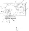
FIG. 1 is a plan view showing the overall configuration of an automatic analyzer according to an embodiment of the present invention.
自動分析装置は、自動分析装置本体10と、第2試薬容器保冷収納部100とを備えている。第2試薬容器保冷収納部100は、自動分析装置本体10に対して、分離、接続可能なものである。図示の状態では、第2試薬容器保冷収納部100は、自動分析装置本体10に接続されている。
The automatic analyzer includes an
自動分析装置本体10は、反応ディスク12を備えている。反応ディスク12には、その円周方向に複数の反応容器12Aが設置されている。反応ディスクが回動することで、所定の反応容器12Aを所定の位置に移動できる。例えば、試料ピペッティング機構13は、試料容器11に保持された試料を吸引し、反応容器12Aの内部に吐出して、試料を分注する。そのために、反応ディスク12が回動して、空の反応容器12Aが試料ピペッティング機構13による試料分注位置に移動する。 The automatic analyzer
試薬ディスク14には、その円周方向に、複数の試薬容器14Aが保持されている。自動分析装置本体10に設置された試薬ディスク14と試薬容器14Aとにより、第1の試薬容器保冷収納部を構成する。試薬ディスク14が回動することで、所定の試薬容器14Aが所定の位置に移動できる。例えば、試薬ピペッティング機構15は、試薬容器14Aに保持された試薬を吸引し、既に試料が分注された反応容器12Aの内部に吐出して、試薬を分注する。試薬ディスク14が回動して、試料の分注された反応容器12Aが試薬ピペッティング機構15による試薬分注位置に移動する。 The
反応ディスク12は恒温槽を備えており、反応容器12Aに試料と試薬が保持され、攪拌され、所定の反応時間が経過すると、光度計16によって反応液の濃度が計測される。 The
第2試薬容器保冷収納部100と自動分析装置本体10との間には、試薬搬送機構20が備えられている。第2試薬容器保冷収納部100は、複数の試薬容器14Bを保持している。図示の例では、5個の試薬容器14Bが保持されている。5個の試薬容器14Bは、ホルダによって保持されており、ホルダ毎、図示の左右方向(X方向)に移動可能である。これにより、所定の試薬容器14Bが試薬搬送機構20の下の搬送位置に移動できる。試薬搬送機構20は、第2試薬容器保冷収納部100の上部に位置する新しい試薬容器を分析装置本体10の試薬ディスク14の内周若しくは外周の位置に搬送できる。また、試薬搬送機構20は、試薬ディスク14上に配置され、しかも、残量の少なくなった試薬容器を、第2試薬容器保冷収納部100に搬出することができる。 A
なお、第1の試薬容器保冷収納部である試薬ディスク14には、常時使用する試薬や依頼の多い試薬などが配置されている。分析装置本体10には、試薬設置位置が設けられている。この設置位置に新しい試薬容器を設置することで、搬送機構20若しくは他の搬送機構を用いて、試薬ディスク14に搬送することができる。すなわち、第2試薬容器保冷収納部と関係の無い動作にて、試薬入搬出が可能である。また、分析装置本体10は、試薬容器の開栓をする開栓機構を備えている。 In addition, the
また、第2試薬容器保冷収納部100には、紙面の奥行き方向(Z方向)に複数の層が積層されて設けられており、各層毎に5個ずつの試薬容器14Bが保持されている。1個の試薬容器14B−1は、下の階層から搬送されてきた試薬容器を図示している。また、試薬容器14B−1の右側で破線で示す矩形は、この位置まで試薬容器14Bが移動可能であることを示している。この移動のためには、後述する水平搬送機構が用いられる。前述のような階層構造とすることで、第2試薬容器保冷収納部100の平面積(設置面積)を大きくすることなく、保持可能な試薬数を増やすことができる。この階層構造については、図2を用いて後述する。また、下層に位置する試薬を上方の試薬搬送位置に移動するための垂直搬送機構を備えているが、この点も図2を用いて後述する。所定の位置に移動された試薬容器14Bは、試薬搬送機構20によって試薬ディスク14に搬出され、収納される。また、試薬のなくなった試薬容器14Aは、試薬搬送機構20によって、第2試薬容器保冷収納部100に戻される。 Further, the second reagent container
次に、図2を用いて、本実施形態による自動分析装置に用いる第2試薬容器保冷収納部100の構成について説明する。
図2は、本発明の一実施形態による自動分析装置に用いる第2試薬容器保冷収納部の構成を示す斜視図である。Next, the configuration of the second reagent container
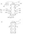
FIG. 2 is a perspective view showing a configuration of a second reagent container cold storage unit used in the automatic analyzer according to the embodiment of the present invention.
第2試薬容器保冷収納部100は、4面の側壁,底面及び上面の6面を囲まれた構成となっている。但し、上面の略中央部には、開口部OPが形成されている。開口部OPは、第2試薬容器保冷収納部100に収納された試薬容器を搬出し、また、自動分析装置本体から移動した試薬容器を搬出するために用いられる。第2試薬容器保冷収納部100は、この開口部OPの箇所を除いて、その内部を略密閉した構成となっている。そして、第2試薬容器保冷収納部100の内部は冷却されることで、内部に収納した試薬の劣化を防止するようにしている。 The second reagent container
第2試薬容器保冷収納部100は、その内部に、第1階層L1,第2階層L2,第3階層L3,第4階層L4,第5階層L5の5階層を備えている。これらの各階層が積層された構成となっている。ここで、例えば、第1階層L1について見ると、5個の試薬容器14BがホルダHDに保持されている。従って、図示の第2試薬容器保冷収納部100は、25個の試薬容器を保持可能である。なお、各階層の保持数を増やしたり、階層の数を増やせば、保持可能な試薬容器の数を増すことはできる。ホルダHDは、左右移動機構により、左右方向(Y方向)に移動可能であり、試薬容器を左右方向に移動可能である。 The second reagent container
図示の状態は、第3階層の試薬容器14Bを垂直搬送機構により上方向に搬送し、第2試薬容器保冷収納部100の上面に設けられた開口部OPまで試薬容器を搬送した状態を示している。 The state shown in the figure shows a state in which the third-
そのため、図示の状態では、第1階層L1の5個の試薬容器14Bは、図示の最も左側の位置に位置している。この位置を退避位置と称する。すなわち、他の階層に収納された試薬容器14Bを、垂直搬送機構110により、上下方向(Z方向)に搬送する際に、第1階層の5個の試薬容器が退避位置に退避していることで、搬送される他の階層の試薬容器と干渉しないように,すなわち、非干渉になる。なお、図示の例では、第2階層L2,第4階層L4,第5階層L5とも、試薬容器は14Bは退避位置に位置している。そして、第3階層L3については、左から3番目(試薬容器の数は5個としているので、右からも3番目)の試薬容器が、垂直搬送機構110により搬送ライン上に位置しており、開口部OPの近傍まで搬出された状態が図示されている。第3階層L3の中央のホルダHDの上は、空であり、試薬容器が搬出された状態を示している。 Therefore, in the state shown in the figure, the five
次に、図3を用いて、本実施形態による自動分析装置に用いる水平搬送機構の構成について説明する。
図3は、本発明の一実施形態による自動分析装置に用いる水平搬送機構の構成を示す平面図である。Next, the configuration of the horizontal transport mechanism used in the automatic analyzer according to the present embodiment will be described with reference to FIG.
FIG. 3 is a plan view showing a configuration of a horizontal transport mechanism used in the automatic analyzer according to the embodiment of the present invention.
水平搬送機構120は、ホルダ支持部122と、回転シャフト124と、モータ126とを備えている。ホルダ支持部122は、複数のホルダHDを一体的に指示し、ホルダHDを左右方向(X方向)に往復動させる。ホルダHDの上には、試薬容器14Dが保持されている。シャフト124は、モータ126の出力軸に連結されている。シャフト124の外周には雄ねじが形成され、一方では、ホルダ支持部122のシャフト124が挿入される部分には雌ねじが形成されている。ホルダ支持部122とシャフト124により送りネジ機構が構成される。モータ126が回転すると、回転シャフト124が回転し、それにより、ホルダ支持部122が直線移動する。 The
図3に示す状態では、5個のホルダHD及びホルダHDに設置された5個の試薬容器14Bは、一番左側の位置,退避位置に退避した状態を示している。このとき、破線で示す位置NIPには、この階層の試薬容器は位置しておらず、紙面の奥方向若しくは手前方向(Z方向)から別の階層の試薬容器を搬送する際に非干渉となる位置である。 In the state shown in FIG. 3, the five holders HD and the five
不干渉位置NIPを垂直搬送機構が通過することで、階層を越えての試薬容器の搬送が可能となる。 As the vertical transport mechanism passes through the non-interference position NIP, the reagent container can be transported across the hierarchy.
ここで、ホルダHDの構成について説明する。ホルダHDの中央部は何もなく、周囲の枠体から、中央部方向に向けて、複数の突起部HD−Aが形成されている。例えば、ホルダHDの右側の辺には、3個の突起部HD−Aが設けられている。3個の突起部HD−Aの両側には、4個の切り欠き部HD−Bが設けられている。また、左側の辺も右側の辺と対称に突起部HD−A及び切り欠き部HD−Bが設けられている。下側の辺には、1個の突起部HD−Aと、その両側に設けられた2個の切り欠き部HD−Bが設けられている。 Here, the configuration of the holder HD will be described. There is no central part of the holder HD, and a plurality of protrusions HD-A are formed from the surrounding frame toward the central part. For example, three protrusions HD-A are provided on the right side of the holder HD. Four notches HD-B are provided on both sides of the three protrusions HD-A. The left side is also provided with a protrusion HD-A and a notch HD-B symmetrically with the right side. On the lower side, one protrusion HD-A and two notches HD-B provided on both sides thereof are provided.
次に、図4及び図5を用いて、本実施形態による自動分析装置に用いる垂直搬送機構の構成について説明する。
図4は、本発明の一実施形態による自動分析装置に用いる垂直搬送機構の構成を示す平面図である。図5は、本発明の一実施形態による自動分析装置に用いる垂直搬送機構の構成を示す部分断面の斜視図である。Next, the configuration of the vertical transport mechanism used in the automatic analyzer according to the present embodiment will be described with reference to FIGS. 4 and 5.
FIG. 4 is a plan view showing a configuration of a vertical transport mechanism used in the automatic analyzer according to the embodiment of the present invention. FIG. 5 is a partial cross-sectional perspective view showing the configuration of the vertical transport mechanism used in the automatic analyzer according to the embodiment of the present invention.
図4(A)は、垂直搬送機構が試薬容器を載置してない状態を示している。 FIG. 4A shows a state where the vertical transport mechanism does not place a reagent container.
図4(A)に示すように、垂直搬送機構110は、アーム112と、シャフト114と、モータ116とを備えている。アーム112は、図示のX−Y平面と平行な平面部を有している。この平面部の左右の辺及び図示の下側の辺には、それぞれ複数の突起部112Aが形成されている。例えば、平面部の右側の辺には、4個の突起部112Aが設けられている。4個の突起部112Aの間には、3個の切り欠き部112Bが設けられている。また、左側の辺も右側の辺と対称に突起部112A及び切り欠き部112Bが設けられている。平面部の下側には、2個の突起部112Aと、その間に設けられた1個の切り欠き部112Bが設けられている。平面部の上側は、シャフト114に連結されている。 As shown in FIG. 4A, the
ここで、図4のアーム112と、図3のホルダHDの構造を比較すると理解されるように、アーム112の突起部112Aは、ホルダHDの切り欠き部HD−Bの位置に設けられている。また、アームの切り欠き部112Bは、ホルダHDの突起部HD−Aの位置に設けられている。従って、例えば、ホルダHDの下方の位置から、アーム112を上昇させると、アーム112は、ホルダHDと接触することなく、ホルダHDの上方の位置まで移動可能である。このとき、ホルダHDの上部に試薬容器が保持されていれば、アーム112は、試薬容器を押し上げて、試薬容器を載置した状態でホルダHDの位置を通り過ぎ、上方に移動することができる。 Here, as can be understood by comparing the structure of the
以上のように、容器配置部であるホルダHDは、平面上の底部の中央が開放され、その底部の周囲の3方向から中央側に向けて突出した複数の突起部HD−Aと、隣接する突起部の間に形成される切り欠き部HD−Bとを備えている。一方、容器搬送部である垂直搬送機構110のアーム112は、試薬容器が載置可能な平面上の底部と、この底部から外周の3方向に向けて突出した複数の突起部112Aと、隣接する突起部の間に形成される切り欠き部112Bとを備えている。すなわち、垂直搬送機構は、前記各階層にて試薬容器が配置される容器配置部に対して相対する形状を有する容器搬送部を備えている。そして、容器配置部の切り欠き部に対して、容器搬送部の前記突起部が上下方向から通過可能な構成となっている。 As described above, the holder HD serving as the container arrangement portion is adjacent to the plurality of protrusions HD-A that are open at the center of the bottom on the plane and protrude from the three directions around the bottom toward the center. And a notch HD-B formed between the protrusions. On the other hand, the
図4(B)及び図5は、アーム112に、試薬容器14Bを載置した状態を示している。突起部112Aは、断面がL字状の形状を有している。すなわち、試薬容器を載置する部分と、載置部分に対して上方に延在した部分である。試薬容器14Bは、3辺に設けられた突起部112Aの延在部分によって囲まれた平面部に保持される。試薬容器14Bの周囲には突起部112Aが設けられているため、試薬容器14Bがアーム112から脱落するのを防止する。また、図5に示すように、突起部112Aの上方の先端は、傾斜部112Cを備えており、試薬容器の位置ずれを補正する。これにより、アーム112により試薬容器を保持する際に、転倒や取り損ねを回避ですることができる。 4B and 5 show a state in which the
次に、図6及び図7を用いて、本実施形態による自動分析装置に用いる垂直搬送機構による試薬容器の搬送状態について説明する。
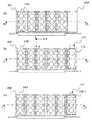
図6は、本発明の一実施形態による自動分析装置に用いる垂直搬送機構による試薬容器の搬送状態を示す平面図である。図7は、本発明の一実施形態による自動分析装置に用いる垂直搬送機構による試薬容器の搬送状態を示す平面図である。ここで、図7(A)は、図6(A)のB−B断面図である。図7(B)は、図6(B)のC−C断面図である。図7(C)は、図6(C)のD−D断面図である。Next, with reference to FIGS. 6 and 7, the state of transport of the reagent container by the vertical transport mechanism used in the automatic analyzer according to the present embodiment will be described.
FIG. 6 is a plan view showing a transport state of the reagent container by the vertical transport mechanism used in the automatic analyzer according to the embodiment of the present invention. FIG. 7 is a plan view showing a transport state of the reagent container by the vertical transport mechanism used in the automatic analyzer according to the embodiment of the present invention. Here, FIG. 7A is a BB cross-sectional view of FIG. FIG. 7B is a cross-sectional view taken along the line CC of FIG. FIG. 7C is a DD cross-sectional view of FIG.
図6(A)及び図7(A)は、不干渉位置NIPに何も無い状態を示している。5個の試薬容器14Bは図示の左側の位置に待避しており、不干渉位置NIPを垂直搬送機構が通過可能となっている。 FIGS. 6A and 7A show a state where there is nothing at the non-interference position NIP. The five
図6(B)及び図7(B)は、不干渉位置NIPに、垂直搬送機構110のアーム112が位置した状態を示している。 FIGS. 6B and 7B show a state where the
図6(C)及び図7(C)は、不干渉位置NIPに、垂直搬送機構110のアーム112が位置し、しかも、アーム112の上に、試薬容器14Bが載置された状態を示している。 6C and 7C show a state in which the
次に、図8及び図9を用いて、本実施形態による自動分析装置に用いる垂直搬送機構により、ある階層から試薬容器を搬送する状態について説明する。
図8は、本発明の一実施形態による自動分析装置に用いる垂直搬送機構により、ある階層から試薬容器を搬送する状態を示す平面図である。図9は、本発明の一実施形態による自動分析装置に用いる垂直搬送機構により、ある階層から試薬容器を搬送する状態を示す平面図である。ここで、図9(A)は、図8(A)のE−E断面図である。図9(B)は、図8(B)のF−F断面図である。図9(C)は、図8(C)のG−G断面図である。Next, a state in which the reagent container is transported from a certain level by the vertical transport mechanism used in the automatic analyzer according to the present embodiment will be described with reference to FIGS.
FIG. 8 is a plan view illustrating a state in which the reagent container is transported from a certain level by the vertical transport mechanism used in the automatic analyzer according to the embodiment of the present invention. FIG. 9 is a plan view showing a state in which the reagent container is transported from a certain level by the vertical transport mechanism used in the automatic analyzer according to the embodiment of the present invention. Here, FIG. 9A is an EE cross-sectional view of FIG. FIG. 9B is a cross-sectional view taken along line FF in FIG. FIG. 9C is a GG cross-sectional view of FIG.
ここでは、ある階層において、5連の試薬容器が配置されている場合に、中央(左から3番目)の試薬容器を搬送する場合について説明する。このとき、試薬容器を保持するホルダは、水平搬送機構により左右方向に移動され、中央の試薬容器を保持するホルダが、垂直搬送機構の動線と交差する位置に配置される。 Here, a case where a central (third from the left) reagent container is transported when five reagent containers are arranged in a certain hierarchy will be described. At this time, the holder that holds the reagent container is moved in the left-right direction by the horizontal transport mechanism, and the holder that holds the central reagent container is arranged at a position that intersects the flow line of the vertical transport mechanism.
図8(A)及び図9(A)は、ホルダHDの中央の位置に何も無い状態を示している。ここでは、試薬容器の保持されてないホルダHDのみが図示されている。 8A and 9A show a state where there is nothing at the center position of the holder HD. Here, only the holder HD in which the reagent container is not held is shown.
図8(B)及び図9(B)は、ホルダHDの中央の位置に、垂直搬送機構110のアーム112が位置した状態を示している。 8B and 9B show a state in which the
図8(C)及び図9(C)は、ホルダHDの中央の位置に、垂直搬送機構110のアーム112が位置し、しかも、アーム112の上に、試薬容器14Bが載置された状態を示している。 8C and 9C show a state in which the
次に、本実施形態の動作について説明する。 Next, the operation of this embodiment will be described.
アーム112とホルダHDの交差する部分は、凹凸(突部と切り欠き部)を有した櫛型をしているため、水平搬送機構によりホルダHDをアーム112の軸線上に移動し、その上で、垂直搬送機構により、アーム112を移動することで、試薬容器の搬出を可能としている。手順としては、垂直搬送機構のアームを最下部で待機させて、搬出したい試薬容器を保持したホルダを昇降位置へ移動させる。このとき同時に、他階層の水平搬送機構は待避位置に移動する。そして、アームが下方から垂直に上昇、ホルダとアームが交差することにより、試薬容器の受け渡しを実現させる。交差のときは、試薬容器の転倒や受け渡しそこねを回避させるために突起部と、その突起の先端の傾斜部が有効になる。 The crossing portion of the
分析装置本体から、自動搬送機によって、戻ってきた試薬容器を第2試薬容器保冷収納庫に収納するときは、最上階の開口部OPから垂直搬送機構110のアーム112へ受け渡しをして、配置可能な空のホルダHDに収納する。収納したい空きホルダがある階層は昇降位置へ移動し、それ以外の階層は、不干渉位置に移動する。 When the returned reagent container is stored in the second reagent container cold storage container from the analyzer main body by the automatic transport machine, it is transferred from the opening OP on the top floor to the
搬入の場合は、ホルダHDに試薬容器を乗せたアーム112を通過させることで、試薬容器の受け渡しを可能としている。手順としては、垂直搬送機構のアームを最上部で試薬容器を保持し待機していて、搬入したい試薬容器を保持させたいホルダを昇降位置へ移動させる。このとき同時に、他階層の水平搬送機構は不干渉位置ができるように移動する。そして、アームが上方から垂直に下降し、ホルダとアームが交差することにより、試薬容器の受け渡しを実現させる。ホルダにもアームと同じく突起部と、その突起部の先端の傾斜部が備わっているため、交差のときに試薬容器の転倒や受け渡しそこねを回避させる
ために112A)突起と、その突起の先端の112C)傾斜構造が有効になる。In the case of carrying in, the reagent container can be delivered by passing the
第2試薬容器保冷収納部は試薬の保冷の為の冷蔵庫として独立稼動させることも可能なため、装置本体が故障しても、試薬の劣化を防ぐことができる。開閉扉があり、試薬容器を手動でも配置することが可能であり、試薬容器に内蔵されているバーコードまたはIDチップなどで、位置情報が取得できる。 Since the second reagent container cold storage unit can be operated independently as a refrigerator for cold storage of the reagent, it is possible to prevent deterioration of the reagent even if the apparatus main body breaks down. There is an open / close door, the reagent container can be manually arranged, and position information can be acquired by a barcode or ID chip built in the reagent container.
以上の説明では、例としてホルダHDの中央部は何もなく、周囲の枠体から、中央部方向に向けて、複数の突起部HD−Aが形成されている構成について説明したが、この形状に限定されるものではなく図10に示すような構成でもよい。図10(A)、(B)夫々は、ホルダHDの別の構成を示す図である。左図は、ホルダHDの中央の位置に、垂直搬送機構110のアーム112が位置し、しかも、アーム112の上に、試薬容器14Bが載置された状態を示す図である。中央図は、ホルダHDの中央の位置に、垂直搬送機構110のアーム112が位置した状態を示す図である。右図は、ホルダHDの中央の位置に何も無い状態を示す図である。 In the above description, the configuration in which the center portion of the holder HD is not provided and a plurality of protrusions HD-A are formed from the surrounding frame toward the center portion has been described as an example. The configuration as shown in FIG. 10 is not limited thereto. FIGS. 10A and 10B are diagrams showing another configuration of the holder HD. The left figure is a diagram showing a state in which the
図10(A)においては、試薬容器14Bは、ホルダHDの四隅に形成された支持部材により保持され、アーム112は、この支持部材と干渉することなく、垂直方向(紙面手間方向)に通過可能である。また、図10(B)においては、試料容器14Bは、ホルダHDの上方の二隅に形成された支持部および下方に形成された支持部の双方により保持され、アーム112は、この支持部材と干渉することなく、垂直方向(紙面手間方向)に通過可能である。これらの例から理解されるように、垂直搬送機構と試薬容器が配置される容器配置部であるホルダHDの構造は、垂直搬送機構が容器配置部を垂直方向に通過できる構造であればよい。この構造により、垂直搬送機構がホルダHDを介して上昇、または、下降することで、ホルダHDから垂直搬送機構への試料容器の受け渡し、または、この逆の受け渡しを実現することができる。 In FIG. 10A, the
なお、以上の説明では、水平搬送機構120は水平方向(図2における左右方向)に試薬容器を往復動できるものであるが、例えば、水平搬送機構は、円周方向に、かつ、水平方向に試薬容器を搬送できるものであってもよい。この場合、試薬容器の水平方向の搬送軌道は、ループ状であり、エンドレスであるため、左右に往復動させる場合に比べて、無駄なスペースを回避することができる。 In the above description, the
以上説明したように、本実施形態によれば,大規模病院や大規模検査室においては、常時使用する試薬と仕様が稀な試薬を自動選択することで、大型の自動分析装置を購入する必要がないため、低価格化と小型化に寄与できる。 As described above, according to this embodiment, in a large-scale hospital or a large-scale laboratory, it is necessary to purchase a large-sized automatic analyzer by automatically selecting a reagent that is always used and a reagent with a rare specification. Therefore, it can contribute to cost reduction and downsizing.
また、本体から剥離させることにより、試薬の保冷の為の冷蔵庫として独立稼動させることも可能な為、装置本体が故障しても、試薬の劣化を防ぐことができる。
Moreover, since it can be made to operate independently as a refrigerator for keeping the reagent cold by peeling from the main body, it is possible to prevent the reagent from deteriorating even if the apparatus main body fails.
10…分析装置本体
14…試薬ディスク
14A,14B…試薬容器
20…自動搬送機構
100…第2試薬容器収納部
110…垂直搬送機構
112…アーム
112A…突起部
112B…切り欠き部
112C…傾斜部
120…水平搬送機構
HD…ホルダ
OP…開口部
L…階層DESCRIPTION OF
DESCRIPTION OF
Claims (7)
Translated fromJapanese前記分析装置本体とは別体に接続分離可能に設けられ、複数の試薬容器を収納保管する第2の試薬収納保管部と、
該第2の試薬収納保管部と前記第1の試薬収納保管部との間で、試薬容器の搬入搬出を行う搬送機構部とを備え、
前記第2の試薬収納保管部は、前記搬送機構部による前記試薬容器の搬出入を行うための開口部を最上階層に設けた階層構造を有し、各階層毎にそれぞれ複数の試薬容器を保管し、
さらに、各階層に保管された試薬容器が配置される容器配置部を前記試薬容器とともに一体的に水平方向に搬送する水平搬送機構部と、
前記容器配置部の前記試薬容器に対応する位置に設けられた開放部を垂直方向に通過可能に設けられ、最上階層以外に保管された試薬容器を最上階層に垂直方向に搬送する垂直搬送機構部とを備えることを特徴とする自動分析装置。A first reagent storage / storage unit that stores and stores a plurality of reagent containers in the analyzer main body, a reaction container placement unit in which a plurality of reaction containers are installed, and aspirated from the reagent containers stored in the reagent storage / storage unit An automatic analyzer having a dispensing mechanism that discharges a reagent to a reaction container of the reaction container disposition unit, and an analysis unit that analyzes a reaction solution reacted in the reaction container,
A second reagent storage / storage unit that is provided separately from the analyzer main body so as to be connectable and separable, and stores and stores a plurality of reagent containers;
A transport mechanism for carrying in and out of the reagent container between the second reagent storage and storage unit and the first reagent storage and storage unit;
The second reagent storage and storage unit hasa hierarchical structure in whichan opening for carrying in and out the reagent container by the transport mechanism unit is provided in the uppermost layer, and stores a plurality of reagent containers for each layer. And
Furthermore, a horizontal transport mechanism unit that transports acontainer placement unit in which reagent containers stored in each layerare disposedtogether with the reagent container in a horizontal direction;
A vertical transport mechanism unitthat is provided so as to be able to pass in the vertical direction through an open portion provided at a position corresponding to the reagent container of the container placement unit, and that transports a reagent container stored in a place other than the top layer in the vertical direction to the top layer And an automatic analyzer.
前記垂直搬送機構部は、前記各階層にて試薬容器が配置される容器配置部に対して相対する形状を有する容器搬送部を備え、
該容器搬送部は、試薬容器を囲み保持することを特徴とする自動分析装置。The automatic analyzer according to claim1 , wherein
The vertical transport mechanism unit includes a container transport unit having a shape facing a container placement unit in which a reagent container is placed in each of the layers,
The automatic analyzer is characterized in that the container transport unit surrounds and holds a reagent container.
前記容器配置部は、平面上の底部の中央が開放され、その底部の周囲の3方向から中央側に向けて突出した複数の突起部と、隣接する突起部の間に形成される切り欠き部とを備え、
前記容器搬送部は、試薬容器が載置可能な平面上の底部と、この底部から外周の3方向に向けて突出した複数の突起部と、隣接する突起部の間に形成される切り欠き部とを備え、
前記容器配置部の前記切り欠き部に対して、前記容器搬送部の前記突起部が上下方向から通過可能であることを特徴とする自動分析装置。The automatic analyzer according to claim2 ,
The container placement portion has a notch portion formed between a plurality of protrusion portions that are open toward the center side from the three directions around the bottom portion of the bottom portion on the plane and adjacent protrusion portions. And
The container transport unit includes a bottom part on a plane on which the reagent container can be placed, a plurality of projecting parts projecting from the bottom part in three directions on the outer periphery, and a notch part formed between adjacent projecting parts. And
The automatic analyzer is characterized in that the protruding portion of the container transport section can pass from above and below the cutout portion of the container placement section.
前記容器搬送部の突起部は、断面がL字状の形状を有しており、試薬容器を載置する部分と、載置部分に対して上方に延在した部分とを有することを特徴とする自動分析装置。The automatic analyzer according to claim3 ,
Projections of the container conveyor in cross section has an L shape, and a portion for mounting a reagent container, andTurkey which have a a portion extending upwardly with respect to mounting portionautomated analyzer according to claim.
前記上方に延在した部分は、先端内周側に傾斜部を備えていることを特徴とする自動分析装置。The automatic analyzer according to claim4 ,
The automatic analyzer according to claim 1, wherein the upwardly extending portion includes an inclined portion on the inner peripheral side of the tip.
前記垂直搬送機構部は、前記水平搬送機構部によって前記垂直搬送機構部の通過位置に搬送された前記容器配置部を下方から上方に向かって通過することにより、前記容器配置部に配置された前記試薬容器を垂直方向に搬送することを特徴とする自動分析装置。 The vertical transport mechanism section is disposed in the container placement section by passing from the bottom to the top through the container placement section transported to the passing position of the vertical transport mechanism section by the horizontal transport mechanism section. An automatic analyzer characterized by transporting a reagent container in a vertical direction.
前記垂直搬送機構部は、前記試薬容器が載置可能な平面上の底部と、この底部から外周の3方向に向けて突出した複数の突起部と、隣接する突起部の間に形成される切り欠き部とを備えた容器搬送部を有し、 The vertical transport mechanism section includes a bottom portion on a plane on which the reagent container can be placed, a plurality of protrusion portions protruding from the bottom portion in three directions on the outer periphery, and a cut formed between adjacent protrusion portions. A container transport section with a notch,
前記容器搬送部は、前記容器配置部の開放部を垂直方向に通過可能であることを特徴とする自動分析装置。 The automatic analyzer according to claim 1, wherein the container transport section is capable of passing through an open portion of the container placement section in a vertical direction.
Priority Applications (1)
| Application Number | Priority Date | Filing Date | Title |
|---|---|---|---|
| JP2012001655AJP5850751B2 (en) | 2012-01-06 | 2012-01-06 | Automatic analyzer |
Applications Claiming Priority (1)
| Application Number | Priority Date | Filing Date | Title |
|---|---|---|---|
| JP2012001655AJP5850751B2 (en) | 2012-01-06 | 2012-01-06 | Automatic analyzer |
Publications (2)
| Publication Number | Publication Date |
|---|---|
| JP2013142560A JP2013142560A (en) | 2013-07-22 |
| JP5850751B2true JP5850751B2 (en) | 2016-02-03 |
Family
ID=49039200
Family Applications (1)
| Application Number | Title | Priority Date | Filing Date |
|---|---|---|---|
| JP2012001655AActiveJP5850751B2 (en) | 2012-01-06 | 2012-01-06 | Automatic analyzer |
Country Status (1)
| Country | Link |
|---|---|
| JP (1) | JP5850751B2 (en) |
Families Citing this family (5)
| Publication number | Priority date | Publication date | Assignee | Title |
|---|---|---|---|---|
| ES2940487T3 (en)* | 2019-06-06 | 2023-05-08 | Siemens Healthcare Diagnostics Products Gmbh | Device for storing reagent containers on several levels |
| EP3922994A1 (en)* | 2020-06-09 | 2021-12-15 | Siemens Healthcare Diagnostics Products GmbH | Device for processing multi-level reagent vessels |
| US20240192238A1 (en) | 2021-05-18 | 2024-06-13 | Hitachi High-Tech Corporation | Sample container and automatic analyzer |
| CN113588974A (en)* | 2021-08-19 | 2021-11-02 | 基蛋生物科技股份有限公司 | Sample analysis system and medical equipment |
| US20240142483A1 (en)* | 2022-10-28 | 2024-05-02 | Sysmex Corporation | Specimen measurement apparatus and specimen transport device |
Family Cites Families (10)
| Publication number | Priority date | Publication date | Assignee | Title |
|---|---|---|---|---|
| JPH01143704U (en)* | 1988-03-28 | 1989-10-03 | ||
| JPH068319U (en)* | 1992-06-30 | 1994-02-01 | 株式会社島津製作所 | Sample transport mechanism in analyzer |
| DE4416103C2 (en)* | 1994-04-19 | 1999-01-07 | Bellheimer Metallwerk Gmbh | high level rack |
| JP5199548B2 (en)* | 2006-05-26 | 2013-05-15 | ベックマン コールター, インコーポレイテッド | Equipment management system |
| JP2006347773A (en)* | 2006-09-22 | 2006-12-28 | Hitachi Koki Co Ltd | Automatic storage device |
| JP2006337386A (en)* | 2006-09-25 | 2006-12-14 | Hitachi High-Technologies Corp | Automatic analyzer |
| US8556564B2 (en)* | 2007-06-26 | 2013-10-15 | Siemens Healthcare Diagnostics Inc. | Mobile sample storage and retrieval unit for a laboratory automated sample handling worksystem |
| JP4558017B2 (en)* | 2007-07-31 | 2010-10-06 | 株式会社日立ハイテクノロジーズ | Automatic analyzer and method of using the automatic analyzer |
| ES2643134T3 (en)* | 2008-11-28 | 2017-11-21 | F. Hoffmann-La Roche Ag | System and method for processing liquid samples |
| US8318499B2 (en)* | 2009-06-17 | 2012-11-27 | Abbott Laboratories | System for managing inventories of reagents |
- 2012
- 2012-01-06JPJP2012001655Apatent/JP5850751B2/enactiveActive
Also Published As
| Publication number | Publication date |
|---|---|
| JP2013142560A (en) | 2013-07-22 |
Similar Documents
| Publication | Publication Date | Title |
|---|---|---|
| CN102818907B (en) | Automatic analyzer | |
| JP4128449B2 (en) | Automatic analyzer | |
| US10359441B2 (en) | Reagent station for an automated analysis device | |
| WO2010090138A1 (en) | Autoanalyzer and rack transfer method | |
| JP5850751B2 (en) | Automatic analyzer | |
| JP6348816B2 (en) | Automatic analyzer | |
| US9889443B2 (en) | Sample analyzer and sample analyzing method | |
| US9804180B2 (en) | Incubation device and methods for automatic movement of a reaction vessel therein for an automatic analysis apparatus | |
| CN111033267A (en) | Automatic analyzer | |
| WO2007139212A1 (en) | Automatic analyzer | |
| JP6494914B2 (en) | Automatic analyzer | |
| JP2025134797A (en) | Automated diagnostic analyzer for liquid samples | |
| US10527637B2 (en) | Automatic analysis device | |
| JP7234328B2 (en) | automatic analyzer | |
| JP7053898B2 (en) | Automated analysis system and sample transport method | |
| JP7456008B2 (en) | Automatic analyzer and how to store reagents in the automatic analyzer | |
| CN107037225B (en) | Container storage rack and analysis device | |
| CN118901014A (en) | Automatic analysis device | |
| WO2022230502A1 (en) | Automated analysis device | |
| CN110609148A (en) | Support adjustment member, container accommodation bracket and analysis device | |
| JP5276085B2 (en) | Box stocker | |
| JP2025144280A (en) | automatic analyzer | |
| JP5321324B2 (en) | Automatic analyzer capable of switching reaction vessel supply means | |
| WO2023008069A1 (en) | Automatic analysis device, and guidance method used in automatic analysis device | |
| CN119555945A (en) | Automatic analysis device and adapter |
Legal Events
| Date | Code | Title | Description |
|---|---|---|---|
| A621 | Written request for application examination | Free format text:JAPANESE INTERMEDIATE CODE: A621 Effective date:20141022 | |
| RD02 | Notification of acceptance of power of attorney | Free format text:JAPANESE INTERMEDIATE CODE: A7422 Effective date:20141022 | |
| A977 | Report on retrieval | Free format text:JAPANESE INTERMEDIATE CODE: A971007 Effective date:20150630 | |
| A131 | Notification of reasons for refusal | Free format text:JAPANESE INTERMEDIATE CODE: A131 Effective date:20150804 | |
| A521 | Written amendment | Free format text:JAPANESE INTERMEDIATE CODE: A523 Effective date:20151005 | |
| TRDD | Decision of grant or rejection written | ||
| A01 | Written decision to grant a patent or to grant a registration (utility model) | Free format text:JAPANESE INTERMEDIATE CODE: A01 Effective date:20151110 | |
| A61 | First payment of annual fees (during grant procedure) | Free format text:JAPANESE INTERMEDIATE CODE: A61 Effective date:20151201 | |
| R150 | Certificate of patent or registration of utility model | Ref document number:5850751 Country of ref document:JP Free format text:JAPANESE INTERMEDIATE CODE: R150 | |
| S531 | Written request for registration of change of domicile | Free format text:JAPANESE INTERMEDIATE CODE: R313531 | |
| S533 | Written request for registration of change of name | Free format text:JAPANESE INTERMEDIATE CODE: R313533 | |
| R350 | Written notification of registration of transfer | Free format text:JAPANESE INTERMEDIATE CODE: R350 |