Movatterモバイル変換


[0]ホーム

URL:


JP5848451B1 - Construction machine control system, construction machine, and construction machine control method - Google Patents

Construction machine control system, construction machine, and construction machine control method
Download PDF

Info

Publication number
JP5848451B1
JP5848451B1JP2014528363AJP2014528363AJP5848451B1JP 5848451 B1JP5848451 B1JP 5848451B1JP 2014528363 AJP2014528363 AJP 2014528363AJP 2014528363 AJP2014528363 AJP 2014528363AJP 5848451 B1JP5848451 B1JP 5848451B1
Authority
JP
Japan
Prior art keywords
bucket
data
boom
arm
axis
Prior art date
Legal status (The legal status is an assumption and is not a legal conclusion. Google has not performed a legal analysis and makes no representation as to the accuracy of the status listed.)
Active
Application number
JP2014528363A
Other languages
Japanese (ja)
Other versions
JPWO2015186180A1 (en
Inventor
仁 北嶋
仁 北嶋
和生 竹原
和生 竹原
Current Assignee (The listed assignees may be inaccurate. Google has not performed a legal analysis and makes no representation or warranty as to the accuracy of the list.)
Komatsu Ltd
Original Assignee
Komatsu Ltd
Priority date (The priority date is an assumption and is not a legal conclusion. Google has not performed a legal analysis and makes no representation as to the accuracy of the date listed.)
Filing date
Publication date
Application filed by Komatsu LtdfiledCriticalKomatsu Ltd
Application grantedgrantedCritical
Publication of JP5848451B1publicationCriticalpatent/JP5848451B1/en
Publication of JPWO2015186180A1publicationCriticalpatent/JPWO2015186180A1/en
Activelegal-statusCriticalCurrent
Anticipated expirationlegal-statusCritical

Links

Images

Classifications

Landscapes

Abstract

Translated fromJapanese

制御システムは、チルト式のバケットを含む作業機を備える建設機械を制御する。制御システムは、寸法データを取得する第1取得部と、バケットの外形データを取得する第2取得部と、バケット軸と直交する作業機動作平面における掘削対象の2次元の目標形状である目標掘削地形を示す目標掘削地形データを取得する第3取得部と、作業機角度データを取得する第4取得部と、バケットの回転角度を示すチルト角度データを取得する第5取得部と、寸法データ、外形データ、作業機角度データ、及びチルト角度データに基づいて、作業機動作平面におけるバケットの外形を示す2次元バケットデータを求める演算部と、を備える。The control system controls a construction machine including a work machine including a tilt type bucket. The control system includes a first acquisition unit that acquires dimension data, a second acquisition unit that acquires outer shape data of the bucket, and a target excavation that is a two-dimensional target shape of an excavation target in a work machine operation plane orthogonal to the bucket axis. A third acquisition unit for acquiring target excavation landform data indicating terrain, a fourth acquisition unit for acquiring work implement angle data, a fifth acquisition unit for acquiring tilt angle data indicating the rotation angle of the bucket, dimension data, A calculation unit that obtains two-dimensional bucket data indicating the outer shape of the bucket on the work machine operation plane based on the outer shape data, the work machine angle data, and the tilt angle data.

Description

Translated fromJapanese

本発明は、建設機械の制御システム、建設機械、及び建設機械の制御方法に関する。  The present invention relates to a construction machine control system, a construction machine, and a construction machine control method.

油圧ショベルのような建設機械は、ブームとアームとバケットとを含む作業機を備える。建設機械の制御において、特許文献1及び特許文献2に開示されているような、掘削対象の目標形状である目標掘削地形に基づいてバケットを移動させる制限掘削制御が知られている。  A construction machine such as a hydraulic excavator includes a work machine including a boom, an arm, and a bucket. In the control of construction machines, limited excavation control that moves a bucket based on a target excavation landform that is a target shape to be excavated as disclosed in Patent Document 1 andPatent Document 2 is known.

国際公開第2012/127913号International Publication No. 2012/127913国際公開第2012/127914号International Publication No. 2012/127914

建設機械において、チルト可能なチルト式バケットが知られている。バケットのチルトによりバケットのチルト角度が変動すると、バケットの刃先の位置が正確に把握できなくなる。その結果、掘削精度が低下し、所期の施工を実行できなくなる可能性がある。  In construction machines, tiltable buckets that can be tilted are known. If the tilt angle of the bucket varies due to the tilt of the bucket, the position of the blade edge of the bucket cannot be accurately grasped. As a result, excavation accuracy is reduced, and the intended construction may not be performed.

本発明の態様は、チルト式バケットを用いる場合においても、掘削精度の低下を抑制できる建設機械の制御システム、建設機械、及び建設機械の制御方法を提供することを目的とする。  An object of an aspect of the present invention is to provide a construction machine control system, a construction machine, and a construction machine control method capable of suppressing a decrease in excavation accuracy even when a tilt bucket is used.

本発明の第1の態様は、ブーム軸を中心に車両本体に対して回転可能なブームと、前記ブーム軸と平行なアーム軸を中心に前記ブームに対して回転可能なアームと、前記アーム軸と平行なバケット軸及び前記バケット軸と直交するチルト軸のそれぞれを中心に前記アームに対して回転可能なバケットとを含む作業機を備える建設機械の制御システムであって、前記ブームの寸法、前記アームの寸法、及び前記バケットの寸法を含む寸法データを取得する第1取得部と、前記バケットの外形データを取得する第2取得部と、前記バケット軸と直交する作業機動作平面における掘削対象の2次元の目標形状である目標掘削地形を示す目標掘削地形データを取得する第3取得部と、前記ブーム軸を中心とする前記ブームの回転角度を示すブーム角度データ、前記アーム軸を中心とする前記アームの回転角度を示すアーム角度データ、及び前記バケット軸を中心とする前記バケットの回転角度を示すバケット角度データを含む作業機角度データを取得する第4取得部と、前記チルト軸を中心とする前記バケットの回転角度を示すチルト角度データを取得する第5取得部と、前記寸法データ、前記外形データ、前記作業機角度データ、及びチルト角度データに基づいて、前記作業機動作平面における前記バケットの外形を示す2次元バケットデータを求める演算部と、を備える建設機械の制御システムを提供する。  According to a first aspect of the present invention, there is provided a boom rotatable with respect to a vehicle body about a boom axis, an arm rotatable with respect to the boom about an arm axis parallel to the boom axis, and the arm axis A construction machine control system comprising: a bucket axis parallel to the bucket axis; and a bucket that is rotatable with respect to the arm about each of a tilt axis orthogonal to the bucket axis, the dimensions of the boom, A first acquisition unit that acquires dimensional data including the dimensions of the arm and the bucket, a second acquisition unit that acquires the outer shape data of the bucket, and an excavation target in a work machine operation plane orthogonal to the bucket axis. A third acquisition unit that acquires target excavation landform data indicating a target excavation landform that is a two-dimensional target shape; and a boom angle that indicates a rotation angle of the boom about the boom axis And a work machine angle data including a bucket angle data indicating a rotation angle of the bucket with the bucket axis as a center, and arm angle data indicating a rotation angle of the arm with the arm axis as a center. Based on an acquisition unit, a fifth acquisition unit that acquires tilt angle data indicating the rotation angle of the bucket about the tilt axis, the dimension data, the outer shape data, the work implement angle data, and the tilt angle data A construction machine control system comprising: a calculation unit that obtains two-dimensional bucket data indicating an outer shape of the bucket in the work machine operation plane.

本発明の第1の態様において、前記バケットの外形データは、前記バケットの幅方向に関して一端部における前記バケットの第1輪郭データと、他端部における前記バケットの第2輪郭データとを含み、前記演算部は、前記第1輪郭データと、前記作業機動作平面の位置と、バケット刃先の位置とに基づいて、前記2次元バケットデータを求めることが好ましい。  In the first aspect of the present invention, the outer shape data of the bucket includes first contour data of the bucket at one end with respect to a width direction of the bucket, and second contour data of the bucket at the other end, It is preferable that the calculation unit obtains the two-dimensional bucket data based on the first contour data, the position of the work machine operation plane, and the position of the bucket blade edge.

本発明の第1の態様において、前記演算部は、前記2次元バケットデータ、前記車両本体の現在位置を示す車両本体位置データ、及び前記車両本体の姿勢を示す車両本体姿勢データに基づいて、前記目標掘削地形と前記バケットとの相対位置を求めることが好ましい。  In the first aspect of the present invention, the computing unit is based on the two-dimensional bucket data, the vehicle body position data indicating the current position of the vehicle body, and the vehicle body attitude data indicating the attitude of the vehicle body. It is preferable to obtain a relative position between the target excavation landform and the bucket.

本発明の第1の態様において、前記第3取得部は、前記目標掘削地形を含み、掘削対象の3次元の目標形状である立体設計地形を示す目標施工情報を取得し、前記演算部は、前記作業機角度データ、前記チルト角度データ、前記車両本体位置データ、前記車両本体姿勢データ、及び前記バケットの外形データに基づいて、前記バケットの先端部及び前記バケットの外面に定められた複数の計測点のうち前記立体設計地形の表面に最も近い最接近点を求め、前記作業機動作平面は、前記最接近点を通ることが好ましい。  In the first aspect of the present invention, the third acquisition unit acquires target construction information that includes the target excavation landform and indicates a three-dimensional design landform that is a three-dimensional target shape of an excavation target, and the calculation unit includes: Based on the work implement angle data, the tilt angle data, the vehicle main body position data, the vehicle main body posture data, and the outer shape data of the bucket, a plurality of measurements determined on the tip of the bucket and the outer surface of the bucket Of the points, it is preferable that the closest approach point to the surface of the three-dimensional design landform is obtained, and the work implement operation plane passes through the closest approach point.

本発明の第1の態様において、前記2次元バケットデータに基づいて、前記作業機を制御する作業機制御部を備えることが好ましい。  1st aspect of this invention WHEREIN: It is preferable to provide the working machine control part which controls the said working machine based on the said two-dimensional bucket data.

本発明の第1の態様において、前記2次元バケットデータは、前記作業機動作平面における前記バケットの現在位置を示すバケット位置データを含み、前記作業機制御部は、前記目標掘削地形データと前記バケット位置データとに基づいて、前記目標掘削地形と前記バケットとの距離に応じて制限速度を決定し、前記作業機が前記目標掘削地形に接近する方向の速度が前記制限速度以下になるように前記ブームの速度を制限することが好ましい。  In the first aspect of the present invention, the two-dimensional bucket data includes bucket position data indicating a current position of the bucket in the work machine operation plane, and the work machine control unit includes the target excavation landform data and the bucket Based on the position data, the speed limit is determined according to the distance between the target excavation landform and the bucket, and the speed in the direction in which the work machine approaches the target excavation landform is equal to or less than the speed limit. It is preferable to limit the speed of the boom.

本発明の第1の態様において、前記2次元バケットデータは、前記作業機動作平面における前記バケットの現在位置を示すバケット位置データを含み、前記目標掘削地形データ及び前記バケット位置データを表示する表示部を備えることが好ましい。  In the first aspect of the present invention, the two-dimensional bucket data includes bucket position data indicating a current position of the bucket in the work machine operation plane, and displays the target excavation landform data and the bucket position data. It is preferable to provide.

本発明の第2の態様は、下部走行体と、前記下部走行体に支持される上部旋回体と、ブームとアームとバケットとを含み、前記上部旋回体に支持される作業機と、第1の態様の制御システムと、を備える建設機械を提供する。  A second aspect of the present invention includes a lower traveling body, an upper swing body supported by the lower traveling body, a boom, an arm, and a bucket, and a work implement supported by the upper swing body, And a control system according to the above aspect.

本発明の第3の態様は、ブーム軸を中心に車両本体に対して回転可能なブームと、前記ブーム軸と平行なアーム軸を中心に前記ブームに対して回転可能なアームと、前記アーム軸と平行なバケット軸及び前記バケット軸と直交するチルト軸のそれぞれを中心に前記アームに対して回転可能なバケットとを含む作業機を備える建設機械の制御方法であって、前記ブームの寸法、前記アームの寸法、及び前記バケットの寸法を含む寸法データを取得することと、前記バケットの外形データを取得することと、前記ブーム軸を中心とする前記ブームの回転角度を示すブーム角度データ、前記アーム軸を中心とする前記アームの回転角度を示すアーム角度データ、及び前記バケット軸を中心とする前記バケットの回転角度を示すバケット角度データを含む作業機角度データを取得することと、前記チルト軸を中心とする前記バケットの回転角度を示すチルト角度データを取得することと、前記バケット軸と直交する作業機動作平面における掘削対象の2次元の目標形状である目標掘削地形を示す目標掘削地形データを指定することと、前記寸法データ、前記外形データ、前記作業機角度データ、及びチルト角度データに基づいて、前記作業機動作平面における前記バケットの外形を示す2次元バケットデータを求めることと、前記2次元バケットデータに基づいて、前記作業機を制御することと、を含む建設機械の制御方法を提供する。  According to a third aspect of the present invention, there is provided a boom that is rotatable with respect to a vehicle body about a boom axis, an arm that is rotatable with respect to the boom about an arm axis parallel to the boom axis, and the arm axis. A construction machine including a working machine including a bucket shaft that is parallel to the bucket shaft and a bucket that is rotatable with respect to the arm about a tilt shaft that is orthogonal to the bucket shaft, the dimensions of the boom, Obtaining dimension data including the dimension of the arm and the dimension of the bucket; obtaining outer shape data of the bucket; and boom angle data indicating a rotation angle of the boom about the boom axis; Arm angle data indicating the rotation angle of the arm about the axis, and bucket angle data indicating the rotation angle of the bucket about the bucket axis. Obtaining the work implement angle data, obtaining the tilt angle data indicating the rotation angle of the bucket around the tilt axis, and the two-dimensional excavation target in the work implement operation plane orthogonal to the bucket axis. Designating the target excavation landform data indicating the target excavation landform, which is the target shape, and the bucket in the work implement operation plane based on the dimension data, the outer shape data, the work implement angle data, and the tilt angle data A construction machine control method including obtaining two-dimensional bucket data indicating the outer shape of the machine and controlling the working machine based on the two-dimensional bucket data is provided.

本発明の態様によれば、掘削精度の低下が抑制される。  According to the aspect of the present invention, a decrease in excavation accuracy is suppressed.

図1は、建設機械の一例を示す斜視図である。FIG. 1 is a perspective view showing an example of a construction machine.図2は、バケットの一例を示す側断面図である。FIG. 2 is a side sectional view showing an example of the bucket.図3は、バケットの一例を示す正面図である。FIG. 3 is a front view showing an example of a bucket.図4は、建設機械の一例を模式的に示す側面図である。FIG. 4 is a side view schematically showing an example of the construction machine.図5は、建設機械の一例を模式的に示す背面図である。FIG. 5 is a rear view schematically showing an example of the construction machine.図6は、建設機械の一例を模式的に示す平面図である。FIG. 6 is a plan view schematically showing an example of the construction machine.図7は、バケットの一例を模式的に示す側面図である。FIG. 7 is a side view schematically showing an example of the bucket.図8は、バケットの一例を模式的に示す正面図である。FIG. 8 is a front view schematically showing an example of the bucket.図9は、制御システムの一例を示すブロック図である。FIG. 9 is a block diagram illustrating an example of a control system.図10は、油圧シリンダの一例を示す図である。FIG. 10 is a diagram illustrating an example of a hydraulic cylinder.図11は、ストロークセンサの一例を示す図である。FIG. 11 is a diagram illustrating an example of a stroke sensor.図12は、制限掘削制御の一例を説明するための図である。FIG. 12 is a diagram for explaining an example of limited excavation control.図13は、油圧システムの一例を示す図である。FIG. 13 is a diagram illustrating an example of a hydraulic system.図14は、油圧システムの一例を示す図である。FIG. 14 is a diagram illustrating an example of a hydraulic system.図15は、油圧システムの一例を示す図である。FIG. 15 is a diagram illustrating an example of a hydraulic system.図16は、建設機械の制御方法の一例を示すフローチャートである。FIG. 16 is a flowchart illustrating an example of a construction machine control method.図17Aは、制御システムの一例を示す機能ブロック図である。FIG. 17A is a functional block diagram illustrating an example of a control system.図17Bは、制御システムの一例を示す機能ブロック図である。FIG. 17B is a functional block diagram illustrating an example of a control system.図18は、制限掘削制御の一例を説明するための図である。FIG. 18 is a diagram for explaining an example of limited excavation control.図19は、バケットの一例を模式的に示す図である。FIG. 19 is a diagram schematically illustrating an example of a bucket.図20は、バケットの一例を模式的に示す図である。FIG. 20 is a diagram schematically illustrating an example of a bucket.図21は、バケットの一例を模式的に示す図である。FIG. 21 is a diagram schematically illustrating an example of a bucket.図22は、バケットの一例を模式的に示す図である。FIG. 22 is a diagram schematically illustrating an example of a bucket.図23は、作業機の一例を模式的に示す図である。FIG. 23 is a diagram schematically illustrating an example of a work machine.図24は、バケットの一例を模式的に示す図である。FIG. 24 is a diagram schematically illustrating an example of a bucket.図25は、建設機械の制御方法の一例を説明するための模式図である。FIG. 25 is a schematic diagram for explaining an example of a method for controlling a construction machine.図26は、制限掘削制御の一例を示すフローチャートである。FIG. 26 is a flowchart illustrating an example of limited excavation control.図27は、制限掘削制御の一例を説明するための図である。FIG. 27 is a diagram for explaining an example of limited excavation control.図28は、制限掘削制御の一例を説明するための図である。FIG. 28 is a diagram for explaining an example of limited excavation control.図29は、制限掘削制御の一例を説明するための図である。FIG. 29 is a diagram for describing an example of limited excavation control.図30は、制限掘削制御の一例を説明するための図である。FIG. 30 is a diagram for explaining an example of limited excavation control.図31は、制限掘削制御の一例を説明するための図である。FIG. 31 is a diagram for explaining an example of limited excavation control.図32は、制限掘削制御の一例を説明するための図である。FIG. 32 is a diagram for explaining an example of limited excavation control.図33は、制限掘削制御の一例を説明するための図である。FIG. 33 is a diagram for describing an example of limited excavation control.図34は、制限掘削制御の一例を説明するための図である。FIG. 34 is a diagram for explaining an example of limited excavation control.図35は、建設機械の制御方法の一例を説明するための模式図である。FIG. 35 is a schematic diagram for explaining an example of a method of controlling the construction machine.図36は、表示部の一例を示す図である。FIG. 36 is a diagram illustrating an example of the display unit.図37は、建設機械の制御方法の一例を説明するための模式図である。FIG. 37 is a schematic diagram for explaining an example of a method for controlling a construction machine.図38は、建設機械の制御方法の一例を説明するための模式図である。FIG. 38 is a schematic diagram for explaining an example of a method for controlling a construction machine.図39は、建設機械の制御方法の一例を説明するための模式図である。FIG. 39 is a schematic diagram for explaining an example of a method for controlling a construction machine.図40は、建設機械の制御方法の一例を説明するための模式図である。FIG. 40 is a schematic diagram for explaining an example of a method of controlling the construction machine.

以下、本発明に係る実施形態について図面を参照しながら説明するが、本発明はこれに限定されない。以下で説明する各実施形態の構成要素は、適宜組み合わせることができる。また、一部の構成要素を用いない場合もある。  Hereinafter, embodiments according to the present invention will be described with reference to the drawings, but the present invention is not limited thereto. The components of each embodiment described below can be combined as appropriate. Some components may not be used.

以下の説明においては、グローバル座標系及びローカル座標系のそれぞれを設定し、それら座標系を参照しつつ各部の位置関係について説明する。グローバル座標系は、地球に固定された原点Pr(図4参照)を基準とした座標系である。ローカル座標系は、建設機械CMの車両本体1に固定された原点P0(図4参照)を基準とした座標系である。ローカル座標系を、車両本体座標系、と称してもよい。  In the following description, each of the global coordinate system and the local coordinate system is set, and the positional relationship of each part will be described with reference to these coordinate systems. The global coordinate system is a coordinate system based on the origin Pr (see FIG. 4) fixed to the earth. The local coordinate system is a coordinate system based on the origin P0 (see FIG. 4) fixed to the vehicle body 1 of the construction machine CM. The local coordinate system may be referred to as a vehicle body coordinate system.

以下の説明においては、グローバル座標系を、XgYgZg直交座標系で示す。後述するように、グローバル座標系の基準位置(原点)Pgは、作業エリアに位置する。水平面内の一方向をXg軸方向、水平面内においてXg軸方向と直交する方向をYg軸方向、Xg軸方向及びYg軸方向のそれぞれと直交する方向をZg軸方向とする。また、Xg軸、Yg軸、及びZg軸まわりの回転(傾斜)方向をそれぞれ、θXg、θYg、及びθZg方向とする。Xg軸は、YgZg平面と直交する。Yg軸は、XgZg平面と直交する。Zg軸は、XgYg平面と直交する。XgYg平面は、水平面と平行である。Zg軸方向は、鉛直方向である。  In the following description, the global coordinate system is indicated by an XgYgZg orthogonal coordinate system. As will be described later, the reference position (origin) Pg of the global coordinate system is located in the work area. One direction in the horizontal plane is defined as the Xg axis direction, and a direction orthogonal to the Xg axis direction in the horizontal plane is defined as the Yg axis direction, and a direction orthogonal to each of the Xg axis direction and the Yg axis direction is defined as the Zg axis direction. In addition, the rotation (tilt) directions around the Xg axis, the Yg axis, and the Zg axis are the θXg, θYg, and θZg directions, respectively. The Xg axis is orthogonal to the YgZg plane. The Yg axis is orthogonal to the XgZg plane. The Zg axis is orthogonal to the XgYg plane. The XgYg plane is parallel to the horizontal plane. The Zg axis direction is the vertical direction.

以下の説明においては、ローカル座標系を、XYZ直交座標系で示す。後述するように、ローカル座標系の基準位置(原点)P0は、旋回体3の旋回中心AXに位置する。ある平面内の一方向をX軸方向、その平面内においてX軸方向と直交する方向をY軸方向、X軸方向及びY軸方向のそれぞれと直交する方向をZ軸方向とする。また、X軸、Y軸、及びZ軸まわりの回転(傾斜)方向をそれぞれ、θX、θY、及びθZ方向とする。X軸は、YZ平面と直交する。Y軸は、XZ平面と直交する。Z軸は、XY平面と直交する。  In the following description, the local coordinate system is indicated by an XYZ orthogonal coordinate system. As will be described later, the reference position (origin) P0 of the local coordinate system is located at the turning center AX of the turning body 3. One direction in a certain plane is defined as an X-axis direction, a direction orthogonal to the X-axis direction in the plane is defined as a Y-axis direction, and a direction orthogonal to each of the X-axis direction and the Y-axis direction is defined as a Z-axis direction. Further, the rotation (inclination) directions around the X axis, Y axis, and Z axis are the θX, θY, and θZ directions, respectively. The X axis is orthogonal to the YZ plane. The Y axis is orthogonal to the XZ plane. The Z axis is orthogonal to the XY plane.

[油圧ショベルの全体構成]
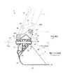
図1は、本実施形態に係る建設機械CMの一例を示す斜視図である。本実施形態においては、建設機械CMが、油圧により作動する作業機2を備える油圧ショベルCMである例について説明する。
[Overall configuration of hydraulic excavator]
FIG. 1 is a perspective view showing an example of the construction machine CM according to the present embodiment. In the present embodiment, an example in which the construction machine CM is a hydraulic excavator CM including thework machine 2 that operates by hydraulic pressure will be described.

図1に示すように、油圧ショベルCMは、車両本体1と、作業機2とを備える。後述するように、油圧ショベルCMには掘削制御を実行する制御システム200が搭載されている。  As shown in FIG. 1, the excavator CM includes a vehicle main body 1 and a work implement 2. As will be described later, the excavator CM is equipped with acontrol system 200 that executes excavation control.

車両本体1は、旋回体3と、運転室4と、走行装置5とを有する。旋回体3は、走行装置5の上に配置される。走行装置5は、旋回体3を支持する。旋回体3を上部旋回体3と称してもよい。走行装置5を下部走行体5と称してもよい。旋回体3は、旋回軸AXを中心に旋回可能である。運転室4に、オペレータが着座する運転席4Sが設けられる。オペレータは、運転室4において油圧ショベルCMを操作する。走行装置5は、一対の履帯5Crを有する。履帯5Crの回転により、油圧ショベルCMが走行する。なお、走行装置5が車輪(タイヤ)を含んでもよい。  The vehicle body 1 includes a turning body 3, acab 4, and a traveling device 5. The swing body 3 is disposed on the traveling device 5. The traveling device 5 supports the revolving unit 3. The swing body 3 may be referred to as the upper swing body 3. The traveling device 5 may be referred to as the lower traveling body 5. The revolving structure 3 can revolve around the revolving axis AX. The driver'scab 4 is provided with a driver'sseat 4S on which an operator sits. The operator operates the excavator CM in thecab 4. The traveling device 5 has a pair of crawler belts 5Cr. The hydraulic excavator CM runs by the rotation of the crawler belt 5Cr. The traveling device 5 may include wheels (tires).

本実施形態においては、運転席4Sを基準として各部の位置関係について説明する。前後方向とは、運転席4Sを基準とした前後方向をいう。左右方向とは、運転席4Sを基準とした左右方向をいう。左右方向は、車幅方向に一致する。運転席4Sが正面に正対する方向を前方向とし、前方向に対向する方向を後方向とする。運転席4Sが正面に正対したとき側方向の右側、左側をそれぞれ右方向、左方向とする。本実施形態において、前後方向は、X軸方向であり、左右方向は、Y軸方向である。運転席4Sが正面に正対する方向は、前方向(+X方向)であり、前方向の反対方向は、後方向(−X方向)である。運転席4Sが正面に正対したときの車幅方向の一側の方向は、右方向(+Y方向)であり、車幅方向の他側の方向は、左方向(−Y方向)である。  In the present embodiment, the positional relationship of each part will be described with reference to the driver'sseat 4S. The front-rear direction refers to the front-rear direction based on the driver'sseat 4S. The left-right direction refers to the left-right direction based on the driver'sseat 4S. The left-right direction coincides with the vehicle width direction. The direction in which the driver'sseat 4S faces the front is the front direction, and the direction facing the front direction is the rear direction. When the driver'sseat 4S faces the front, the right side and the left side of the side direction are the right direction and the left direction, respectively. In the present embodiment, the front-rear direction is the X-axis direction, and the left-right direction is the Y-axis direction. The direction in which the driver'sseat 4S faces the front is the front direction (+ X direction), and the opposite direction to the front direction is the rear direction (−X direction). When the driver'sseat 4S faces the front, one direction in the vehicle width direction is the right direction (+ Y direction), and the other direction in the vehicle width direction is the left direction (−Y direction).

旋回体3は、エンジンが収容されるエンジンルーム9と、旋回体3の後部に設けられるカウンタウェイトとを有する。旋回体3において、エンジンルーム9の前方に手すり19が設けられる。エンジンルーム9に、エンジン及び油圧ポンプなどが配置される。  The swing body 3 has an engine room 9 in which the engine is accommodated, and a counterweight provided at the rear portion of the swing body 3. In the revolving structure 3, ahandrail 19 is provided in front of the engine room 9. In the engine room 9, an engine, a hydraulic pump, and the like are arranged.

作業機2は、旋回体3に接続される。作業機2は、ブームピン13を介して旋回体3に接続されるブーム6と、アームピン14を介してブーム6に接続されるアーム7と、バケットピン15及びチルトピン80を介してアーム7に接続されるバケット8と、ブーム6を駆動するブームシリンダ10と、アーム7を駆動するアームシリンダ11と、バケット8を駆動するバケットシリンダ12及びチルトシリンダ30とを有する。ブーム6の基端部(ブームフート)と旋回体3とが接続される。ブーム6の先端部(ブームトップ)とアーム7の基端部(アームフート)とが接続される。アーム7の先端部(アームトップ)とバケット8の基端部とが接続される。ブームシリンダ10、アームシリンダ11、バケットシリンダ12、及びチルトシリンダ30のそれぞれは、作動油によって駆動される油圧シリンダである。  Thework machine 2 is connected to the swing body 3. The work implement 2 is connected to thearm 7 via a boom 6 connected to the swing body 3 via aboom pin 13, anarm 7 connected to the boom 6 via anarm pin 14, and abucket pin 15 and atilt pin 80. Abucket 8 that drives the boom 6, anarm cylinder 11 that drives thearm 7, and abucket cylinder 12 and atilt cylinder 30 that drive thebucket 8. The base end (boom foot) of the boom 6 and the revolving structure 3 are connected. The tip end portion (boom top) of the boom 6 and the base end portion (arm foot) of thearm 7 are connected. The distal end portion (arm top) of thearm 7 and the proximal end portion of thebucket 8 are connected. Each of theboom cylinder 10, thearm cylinder 11, thebucket cylinder 12, and thetilt cylinder 30 is a hydraulic cylinder driven by hydraulic oil.

作業機2は、ブームシリンダ10に配置され、ブームシリンダ10のストローク長さを検出する第1ストロークセンサ16と、アームシリンダ11に配置され、アームシリンダ11のストローク長さを検出する第2ストロークセンサ17と、バケットシリンダ12に配置され、バケットシリンダ12のストローク長さを検出する第3ストロークセンサ18とを有する。  The work implement 2 is disposed in theboom cylinder 10 and detects a stroke length of theboom cylinder 10. A second stroke sensor is disposed in thearm cylinder 11 and detects the stroke length of thearm cylinder 11. 17 and athird stroke sensor 18 that is disposed in thebucket cylinder 12 and detects the stroke length of thebucket cylinder 12.

ブーム6は、回転軸であるブーム軸J1を中心に旋回体3に対して回転可能である。アーム7は、ブーム軸J1と平行な回転軸であるアーム軸J2を中心にブーム6に対して回転可能である。バケット8は、ブーム軸J1及びアーム軸J2と平行な回転軸であるバケット軸J3を中心にアーム7に対して回転可能である。バケット8は、バケット軸J3と直交する回転軸であるチルト軸J4を中心にアーム7に対して回転可能である。ブームピン13は、ブーム軸J1を含む。アームピン14は、アーム軸J2を含む。バケットピン15は、バケット軸J3を含む。チルトピン80は、チルト軸J4を含む。  The boom 6 can rotate with respect to the revolving structure 3 around a boom axis J1 which is a rotation axis. Thearm 7 is rotatable with respect to the boom 6 about an arm axis J2 which is a rotation axis parallel to the boom axis J1. Thebucket 8 is rotatable with respect to thearm 7 about a bucket axis J3 that is a rotation axis parallel to the boom axis J1 and the arm axis J2. Thebucket 8 is rotatable with respect to thearm 7 about a tilt axis J4 that is a rotation axis orthogonal to the bucket axis J3. Theboom pin 13 includes a boom shaft J1. Thearm pin 14 includes an arm axis J2.Bucket pin 15 includes bucket shaft J3. Thetilt pin 80 includes a tilt axis J4.

本実施形態において、ブーム軸J1、アーム軸J2、及びバケット軸J3のそれぞれは、Y軸と平行である。ブーム6、アーム7、及びバケット8のそれぞれは、θY方向に回転可能である。本実施形態において、XZ平面は、所謂、ブーム6及びアーム7の垂直回動面を含む。  In the present embodiment, each of the boom axis J1, the arm axis J2, and the bucket axis J3 is parallel to the Y axis. Each of the boom 6, thearm 7, and thebucket 8 can rotate in the θY direction. In the present embodiment, the XZ plane includes the so-called vertical rotation surfaces of the boom 6 and thearm 7.

以下の説明においては、ブームシリンダ10のストローク長さを適宜、ブームシリンダ長又はブームストローク、と称し、アームシリンダ11のストローク長さを適宜、アームシリンダ長又はアームストローク、と称し、バケットシリンダ12のストローク長さを適宜、バケットシリンダ長又はバケットストローク、と称し、チルトシリンダ30のストローク長さを適宜、チルトシリンダ長、と称する。また、以下の説明において、ブームシリンダ長、アームシリンダ長、バケットシリンダ長、及びチルトシリンダ長を適宜、シリンダ長データL、と総称する。  In the following description, the stroke length of theboom cylinder 10 is appropriately referred to as a boom cylinder length or a boom stroke, the stroke length of thearm cylinder 11 is appropriately referred to as an arm cylinder length or an arm stroke, and thebucket cylinder 12 The stroke length is appropriately referred to as a bucket cylinder length or a bucket stroke, and the stroke length of thetilt cylinder 30 is appropriately referred to as a tilt cylinder length. In the following description, the boom cylinder length, arm cylinder length, bucket cylinder length, and tilt cylinder length are collectively referred to as cylinder length data L as appropriate.

[バケット]
次に、本実施形態に係るバケット8について説明する。図2は、本実施形態に係るバケット8の一例を示す側断面図である。図3は、本実施形態に係るバケット8の一例を示す正面図である。本実施形態において、バケット8は、チルト式バケットである。
[bucket]
Next, thebucket 8 according to the present embodiment will be described. FIG. 2 is a side sectional view showing an example of thebucket 8 according to the present embodiment. FIG. 3 is a front view showing an example of thebucket 8 according to the present embodiment. In the present embodiment, thebucket 8 is a tilt type bucket.

図2及び図3に示すように、作業機2は、バケット軸J3及びバケット軸J3と直交するチルト軸J4のそれぞれを中心にアーム7に対して回転可能なバケット8とを有する。バケット8は、バケットピン15(バケット軸J3)を中心にアーム7に回転可能に支持されている。バケット8は、チルトピン80(チルト軸J4)を中心にアーム7に回転可能に支持される。バケット軸J3とチルト軸J4とは直交する。バケット8は、バケット軸J3及びそのバケット軸J3と直交するチルト軸J4のそれぞれを中心にアーム7に回転可能に支持される。  As illustrated in FIGS. 2 and 3, thework machine 2 includes a bucket shaft J3 and abucket 8 that can rotate with respect to thearm 7 about each of a tilt shaft J4 orthogonal to the bucket shaft J3. Thebucket 8 is rotatably supported by thearm 7 around a bucket pin 15 (bucket shaft J3). Thebucket 8 is rotatably supported by thearm 7 around a tilt pin 80 (tilt axis J4). Bucket axis J3 and tilt axis J4 are orthogonal to each other. Thebucket 8 is rotatably supported by thearm 7 around the bucket axis J3 and the tilt axis J4 orthogonal to the bucket axis J3.

バケット8は、接続部材(台枠)90を介して、アーム7の先端部に接続される。バケットピン15は、アーム7と接続部材90とを連結する。チルトピン80は、接続部材90とバケット8とを連結する。バケット8は、接続部材90を介して、アーム7に回転可能に接続される。  Thebucket 8 is connected to the distal end portion of thearm 7 via a connecting member (frame) 90. Thebucket pin 15 connects thearm 7 and theconnection member 90. Thetilt pin 80 connects theconnection member 90 and thebucket 8. Thebucket 8 is rotatably connected to thearm 7 via aconnection member 90.

バケット8は、底板81と、背板82と、上板83と、側板84と、側板85とを含む。底板81と上板83と側板84と側板85とによって、バケット8の開口部86が規定される。  Bucket 8 includes abottom plate 81, aback plate 82, anupper plate 83, aside plate 84, and aside plate 85. Thebottom plate 81, theupper plate 83, theside plate 84, and theside plate 85 define theopening 86 of thebucket 8.

バケット8は、上板83の上部に設けられたブラケット87を有する。ブラケット87は、上板83の前後位置に設置される。ブラケット87は接続部材90及びチルトピン80と連結される。  Thebucket 8 has abracket 87 provided on the upper portion of theupper plate 83. Thebracket 87 is installed at the front and rear positions of theupper plate 83. Thebracket 87 is connected to theconnection member 90 and thetilt pin 80.

接続部材90は、プレート部材91と、プレート部材91の上面に設けられたブラケット92と、プレート部材91の下面に設けられたブラケット93とを有する。ブラケット92は、アーム7及び後述する第2リンクピン95と連結される。ブラケット93はブラケット87の上部に設置され、チルトピン80及びブラケット87と連結される。  Theconnection member 90 includes aplate member 91, abracket 92 provided on the upper surface of theplate member 91, and abracket 93 provided on the lower surface of theplate member 91. Thebracket 92 is connected to thearm 7 and asecond link pin 95 described later. Thebracket 93 is installed on the upper portion of thebracket 87 and is connected to thetilt pin 80 and thebracket 87.

バケットピン15は、接続部材90のブラケット92とアーム7の先端部とを連結する。チルトピン80は、接続部材90のブラケット93とバケット8のブラケット87とを連結する。これにより、アーム7に対して接続部材90及びバケット8がバケット軸J3を中心に回転可能となり、接続部材90に対してバケット8がチルト軸J4を中心に回転可能となる。  Thebucket pin 15 connects thebracket 92 of theconnection member 90 and the tip of thearm 7. Thetilt pin 80 connects thebracket 93 of theconnection member 90 and thebracket 87 of thebucket 8. Thereby, theconnection member 90 and thebucket 8 can rotate about the bucket axis J3 with respect to thearm 7, and thebucket 8 can rotate about the tilt axis J4 with respect to theconnection member 90.

作業機2は、第1リンクピン94Pを介してアーム7に回転可能に接続される第1リンク部材94と、第2リンクピン95Pを介してブラケット92に回転可能に接続される第2リンク部材95とを有する。第1リンク部材94の基端部が第1リンクピン94Pを介してアーム7に接続される。第2リンク部材95の基端部が第2リンクピン95Pを介してブラケット92に接続される。第1リンク部材94の先端部と第2リンク部材95の先端部とが、バケットシリンダトップピン96を介して連結される。  The work implement 2 includes a first link member 94 that is rotatably connected to thearm 7 via thefirst link pin 94P, and a second link member that is rotatably connected to thebracket 92 via the second link pin 95P. 95. The base end portion of the first link member 94 is connected to thearm 7 via thefirst link pin 94P. The base end portion of thesecond link member 95 is connected to thebracket 92 via thesecond link pin 95P. The distal end portion of the first link member 94 and the distal end portion of thesecond link member 95 are connected via a bucketcylinder top pin 96.

バケットシリンダ12の先端部は、バケットシリンダトップピン96を介して、第1リンク部材94の先端部及び第2リンク部材95の先端部と回転可能に接続される。バケットシリンダ12が伸縮するように作動すると、接続部材90がバケット8と一緒にバケット軸J3を中心に回転する。  The tip of thebucket cylinder 12 is rotatably connected to the tip of the first link member 94 and the tip of thesecond link member 95 via a bucketcylinder top pin 96. When thebucket cylinder 12 is operated so as to expand and contract, the connectingmember 90 rotates about the bucket axis J3 together with thebucket 8.

チルトシリンダ30は、接続部材90に設けられたブラケット97、及びバケット8に設けられたブラケット88のそれぞれに接続される。チルトシリンダ30のロッドがピンを介してブラケット97に接続される。チルトシリンダ30の本体部がピンを介してブラケット88に接続される。バケットシリンダ30が伸縮するように作動すると、バケット8はチルト軸J4を中心に回転する。  Thetilt cylinder 30 is connected to each of abracket 97 provided on theconnection member 90 and abracket 88 provided on thebucket 8. The rod of thetilt cylinder 30 is connected to thebracket 97 via a pin. The main body of thetilt cylinder 30 is connected to thebracket 88 via a pin. When thebucket cylinder 30 is operated to expand and contract, thebucket 8 rotates about the tilt axis J4.

このように、バケット8は、バケットシリンダ12の作動により、バケット軸J3を中心に回転する。バケット8は、チルトシリンダ30の作動により、チルト軸J4を中心に回転する。本実施形態においては、バケット軸J3を中心とするバケット8の回転により、チルトピン80(チルト軸J4)が、バケット8と一緒に回転(傾斜)する。  Thus, thebucket 8 rotates around the bucket axis J3 by the operation of thebucket cylinder 12. Thebucket 8 rotates around the tilt axis J <b> 4 by the operation of thetilt cylinder 30. In the present embodiment, the tilt pin 80 (tilt axis J4) rotates (tilts) together with thebucket 8 by the rotation of thebucket 8 about the bucket axis J3.

本実施形態において、作業機2は、チルト軸J4を中心とするバケット8の回転角度δを示すチルト角度データを検出するチルト角度センサ70を有する。チルト角度センサ70は、グローバル座標系における水平面に対するバケット8のチルト角度(回転角度)を検出する。チルト角度センサ70は、所謂、2軸の角度センサであり、後述するθXg方向、及びθYg方向に関する2つの方向に関する傾斜角度を検出する。チルト角度センサ70は、バケット8の少なくとも一部に設けられる。グローバル座標系におけるチルト角度は、傾斜センサ24の検出結果に基づいて、ローカル座標系におけるチルト角度δに変換される。  In the present embodiment, the work implement 2 includes atilt angle sensor 70 that detects tilt angle data indicating the rotation angle δ of thebucket 8 about the tilt axis J4. Thetilt angle sensor 70 detects the tilt angle (rotation angle) of thebucket 8 with respect to the horizontal plane in the global coordinate system. Thetilt angle sensor 70 is a so-called biaxial angle sensor, and detects tilt angles in two directions related to a θXg direction and a θYg direction, which will be described later. Thetilt angle sensor 70 is provided on at least a part of thebucket 8. The tilt angle in the global coordinate system is converted into the tilt angle δ in the local coordinate system based on the detection result of thetilt sensor 24.

なお、バケット8は、本実施形態に限定されない。バケット8の傾斜角度(チルト角度)を任意に設定する方法でもよい。傾斜角度の軸は、もう1軸増えてもよい。  Thebucket 8 is not limited to this embodiment. A method of arbitrarily setting the inclination angle (tilt angle) of thebucket 8 may be used. The tilt angle axis may be increased by another axis.

[油圧ショベルの構造]
図4は、本実施形態に係る油圧ショベルCMを模式的に示す側面図である。図5は、本実施形態に係る油圧ショベルCMを模式的に示す背面図である。図6は、本実施形態に係る油圧ショベルCMを模式的に示す平面図である。
[Hydraulic excavator structure]
FIG. 4 is a side view schematically showing the excavator CM according to the present embodiment. FIG. 5 is a rear view schematically showing the excavator CM according to the present embodiment. FIG. 6 is a plan view schematically showing the excavator CM according to the present embodiment.

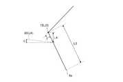
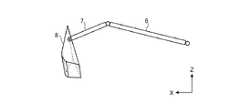
本実施形態においては、ブーム軸J1とアーム軸J2との距離L1を、ブーム長さL1とする。アーム軸J2とバケット軸J3との距離L2を、アーム長さL2とする。バケット軸J3とバケット8の先端部8aとの距離L3を、バケット長さL3とする。  In the present embodiment, the distance L1 between the boom axis J1 and the arm axis J2 is the boom length L1. A distance L2 between the arm axis J2 and the bucket axis J3 is defined as an arm length L2. A distance L3 between the bucket shaft J3 and thetip 8a of thebucket 8 is defined as a bucket length L3.

バケット8の先端部は、バケット8が有する刃の先端部を含む。本実施形態において、バケット8の刃の先端部は、ストレート状である。なお、バケット8は、複数の尖った刃を有してもよい。以下の説明において、バケット8の先端部8aを適宜、刃先8a、と称する。  The tip of thebucket 8 includes the tip of the blade that thebucket 8 has. In the present embodiment, the tip of the blade of thebucket 8 is straight. Thebucket 8 may have a plurality of pointed blades. In the following description, thetip 8a of thebucket 8 is appropriately referred to as ablade edge 8a.

油圧ショベルCMは、作業機2の角度を検出する角度検出装置22を有する。角度検出装置22は、ブーム軸J1を中心とするブーム6の回転角度αを示すブーム角度データ、アーム軸J2を中心とするアーム7の回転角度βを示すアーム角度データ、及びバケット軸J3を中心とするバケット8の回転角度γを示すバケット角度データを含む作業機角度データを検出する。本実施形態において、ブーム角度(回転角度)αは、ローカル座標系のZ軸と平行な軸に対するブーム6の傾斜角度を含む。アーム角度(回転角度)βは、ブーム6に対するアーム7の傾斜角度を含む。バケット角度(回転角度)γは、アーム7に対するバケット8の傾斜角度を含む。  The excavator CM includes anangle detection device 22 that detects the angle of thework machine 2. Theangle detection device 22 has boom angle data indicating the rotation angle α of the boom 6 centered on the boom axis J1, arm angle data indicating the rotation angle β of thearm 7 centered on the arm axis J2, and the bucket axis J3. Working machine angle data including bucket angle data indicating the rotation angle γ of thebucket 8 is detected. In the present embodiment, the boom angle (rotation angle) α includes an inclination angle of the boom 6 with respect to an axis parallel to the Z axis of the local coordinate system. The arm angle (rotation angle) β includes the inclination angle of thearm 7 with respect to the boom 6. The bucket angle (rotation angle) γ includes the inclination angle of thebucket 8 with respect to thearm 7.

本実施形態において、角度検出装置22は、ブームシリンダ10に配置された第1ストロークセンサ16と、アームシリンダ11に配置された第2ストロークセンサ17と、バケットシリンダ12に配置された第3ストロークセンサ18とを含む。第1ストロークセンサ16の検出結果に基づいて、ブームシリンダ長が求められる。第2ストロークセンサ17の検出結果に基づいて、アームシリンダ長が求められる。第3ストロークセンサ18の検出結果に基づいて、バケットシリンダ長が求められる。本実施形態においては、第1ストロークセンサ16でブームシリンダ長が検出されることにより、ブーム角度αが導出又は算出される。第2ストロークセンサ17でアームシリンダ長が検出されることにより、アーム角度βが導出又は算出される。第3ストロークセンサ18でバケットシリンダ長が検出されることにより、バケット角度γが導出又は算出される。  In the present embodiment, theangle detection device 22 includes afirst stroke sensor 16 disposed in theboom cylinder 10, asecond stroke sensor 17 disposed in thearm cylinder 11, and a third stroke sensor disposed in thebucket cylinder 12. 18 and so on. Based on the detection result of thefirst stroke sensor 16, the boom cylinder length is obtained. Based on the detection result of thesecond stroke sensor 17, the arm cylinder length is obtained. Based on the detection result of thethird stroke sensor 18, the bucket cylinder length is obtained. In the present embodiment, the boom angle α is derived or calculated by detecting the boom cylinder length by thefirst stroke sensor 16. When the arm cylinder length is detected by thesecond stroke sensor 17, the arm angle β is derived or calculated. When the bucket cylinder length is detected by thethird stroke sensor 18, the bucket angle γ is derived or calculated.

油圧ショベルCMは、車両本体1の現在位置を示す車両本体位置データP、及び車両本体1の姿勢を示す車両本体姿勢データQを検出可能な位置検出装置20を備えている。車両本体1の現在位置は、グローバル座標系における車両本体1の現在位置(Xg位置、Yg位置、及びZg位置)を含む。車両本体1の姿勢は、θXg方向、θYg方向、及びθZg方向に関する旋回体3の位置を含む。車両本体1の姿勢は、水平面(XgYg平面)に対する旋回体3の左右方向の傾斜角度(ロール角)θ1と、水平面に対する旋回体3の前後方向の傾斜角度(ピッチ角)θ2と、グローバル座標の基準方位(例えば北)と旋回体3(作業機2)が向いている方位とがなす角度(ヨー角)θ3とを含む。  The hydraulic excavator CM includes aposition detection device 20 capable of detecting vehicle body position data P indicating the current position of the vehicle body 1 and vehicle body attitude data Q indicating the attitude of the vehicle body 1. The current position of the vehicle body 1 includes the current position (Xg position, Yg position, and Zg position) of the vehicle body 1 in the global coordinate system. The posture of the vehicle body 1 includes the position of the revolving body 3 with respect to the θXg direction, the θYg direction, and the θZg direction. The posture of the vehicle body 1 is determined by the inclination angle (roll angle) θ1 of the revolving body 3 relative to the horizontal plane (XgYg plane), the inclination angle (pitch angle) θ2 of the revolving body 3 relative to the horizontal plane, It includes an angle (yaw angle) θ3 formed by the reference azimuth (for example, north) and the azimuth that the revolving unit 3 (work machine 2) faces.

位置検出装置20は、アンテナ21と、位置センサ23と、傾斜センサ24とを有する。アンテナ21は、車両本体1の現在位置を検出するためのアンテナである。アンテナ21は、GNSS(Global Navigation Satellite Systems:全地球航法衛星システム)用のアンテナである。アンテナ21は、RTK−GNSS(Real Time Kinematic-Global Navigation Satellite Systems)用アンテナである。アンテナ21は、旋回体3に設けられる。本実施形態において、アンテナ21は、旋回体3の手すり19に設けられる。なお、アンテナ21は、エンジンルーム9の後方向に設けられてよい。例えば、旋回体3のカウンタウェイトにアンテナ21が設けられてもよい。アンテナ21は、受信した電波(GNSS電波)に応じた信号を位置センサ23に出力する。  Theposition detection device 20 includes anantenna 21, aposition sensor 23, and atilt sensor 24. Theantenna 21 is an antenna for detecting the current position of the vehicle body 1. Theantenna 21 is an antenna for GNSS (Global Navigation Satellite Systems). Theantenna 21 is an RTK-GNSS (Real Time Kinematic-Global Navigation Satellite Systems) antenna. Theantenna 21 is provided on the revolving unit 3. In the present embodiment, theantenna 21 is provided on thehandrail 19 of the revolving structure 3. Theantenna 21 may be provided in the rear direction of the engine room 9. For example, theantenna 21 may be provided on the counterweight of the swing body 3. Theantenna 21 outputs a signal corresponding to the received radio wave (GNSS radio wave) to theposition sensor 23.

位置センサ23は、3次元位置センサ及びグローバル座標演算部を含み、グローバル座標系におけるアンテナ21の設置位置Prを検出する。グローバル座標系は、作業エリアに設置した基準位置Pgを元にした3次元座標系である。図4に示すように、本実施形態において、基準位置Pgは、作業エリアに設定された基準杭の先端の位置である。  Theposition sensor 23 includes a three-dimensional position sensor and a global coordinate calculation unit, and detects the installation position Pr of theantenna 21 in the global coordinate system. The global coordinate system is a three-dimensional coordinate system based on the reference position Pg installed in the work area. As shown in FIG. 4, in this embodiment, the reference position Pg is the position of the tip of the reference pile set in the work area.

本実施形態において、アンテナ21は、ローカル座標系のY軸方向(旋回体3の車幅方向)に関して離れるように旋回体3に設けられた第1アンテナ21A及び第2アンテナ21Bを含む。位置センサ23は、第1アンテナ21Aの設置位置Pra及び第2アンテナ21Bの設置位置Prbを検出する。  In the present embodiment, theantenna 21 includes afirst antenna 21 </ b> A and asecond antenna 21 </ b> B provided on the revolving structure 3 so as to be separated from each other in the Y-axis direction (vehicle width direction of the revolving structure 3) of the local coordinate system. Theposition sensor 23 detects the installation position Pra of thefirst antenna 21A and the installation position Prb of thesecond antenna 21B.

位置検出装置20は、位置センサ23を使って、グローバル座標における車両本体位置データP及び車両本体姿勢データQを取得する。車両本体位置データPは、旋回体3の旋回軸(旋回中心)AXに位置する基準位置P0を示すデータである。なお、基準位置データPは、設置位置Prを示すデータでもよい。位置検出装置20は、基準位置P0を含む車両本体位置データPを取得する。また、位置検出装置20は、2つの設置位置Pra及び設置位置Prbに基づいて、車両本体姿勢データQを取得する。車両本体姿勢データQは、設置位置Praと設置位置Prbとで決定される直線がグローバル座標の基準方位(例えば北)に対してなす角に基づいて決定される。車両本体姿勢データQは、旋回体3(作業機2)が向いている方位を示す。  Theposition detection device 20 uses theposition sensor 23 to acquire vehicle body position data P and vehicle body attitude data Q in global coordinates. The vehicle body position data P is data indicating a reference position P0 located on the turning axis (turning center) AX of the turning body 3. The reference position data P may be data indicating the installation position Pr. Theposition detection device 20 acquires vehicle body position data P including the reference position P0. Further, theposition detection device 20 acquires vehicle body attitude data Q based on the two installation positions Pra and the installation position Prb. The vehicle body posture data Q is determined based on an angle formed by a straight line determined by the installation position Pra and the installation position Prb with respect to a reference direction (for example, north) of global coordinates. The vehicle body posture data Q indicates the direction in which the turning body 3 (work machine 2) is facing.

傾斜センサ24は、旋回体3に設けられる。傾斜センサ24は、IMU(Inertial Measurement Unit)を含む。傾斜センサ24は、運転室4の下部に配置される。旋回体3において、運転室4の下部に高剛性のフレームが配置される。なお、傾斜センサ24は、旋回体3の旋回軸AX(基準位置P2)の側方(右側又は左側)に配置されてもよい。傾斜センサ24は、そのフレームに配置される。位置検出装置20は、傾斜センサ24を使って、ロール角θ1及びピッチ角θ2を含む車両本体姿勢データQを取得する。  Thetilt sensor 24 is provided on the revolving structure 3. Theinclination sensor 24 includes an IMU (Inertial Measurement Unit). Theinclination sensor 24 is disposed in the lower part of thecab 4. In the revolving structure 3, a highly rigid frame is disposed below thecab 4. Thetilt sensor 24 may be disposed on the side (right side or left side) of the turning axis AX (reference position P2) of the turning body 3. Thetilt sensor 24 is disposed on the frame. Theposition detection device 20 uses theinclination sensor 24 to acquire vehicle body posture data Q including the roll angle θ1 and the pitch angle θ2.

図7は、本実施形態に係るバケット8を模式的に示す側面図である。図8は、本実施形態に係るバケット8を模式的に示す正面図である。  FIG. 7 is a side view schematically showing thebucket 8 according to the present embodiment. FIG. 8 is a front view schematically showing thebucket 8 according to the present embodiment.

本実施形態においては、バケット軸J3とチルト軸J4との距離L4を、チルト長さL4とする。側板84と側板85との距離L5を、バケット8の幅の寸法L5とする。チルト角度δは、XY平面に対するバケット8の傾斜角度である。チルト角度δを示すチルト角度データは、チルト角度センサ70の検出結果から導出される。チルト軸角度εは、XY平面に対するチルト軸J4(チルトピン80)の傾斜角度である。チルト軸角度εを示すチルト角度データは、角度検出装置22の検出結果から導出される。  In the present embodiment, the distance L4 between the bucket axis J3 and the tilt axis J4 is the tilt length L4. A distance L5 between theside plate 84 and theside plate 85 is defined as a width dimension L5 of thebucket 8. The tilt angle δ is an inclination angle of thebucket 8 with respect to the XY plane. The tilt angle data indicating the tilt angle δ is derived from the detection result of thetilt angle sensor 70. The tilt axis angle ε is an inclination angle of the tilt axis J4 (tilt pin 80) with respect to the XY plane. The tilt angle data indicating the tilt axis angle ε is derived from the detection result of theangle detection device 22.

なお、本実施形態においては、チルト角度データが角度検出装置22の検出結果から取得されることとするが、バケット8のチルト角度は、例えば、チルトシリンダ30のストローク長さ(チルトシリンダ長)を検出した検出結果から算出し、取得することも可能である。  In the present embodiment, the tilt angle data is acquired from the detection result of the
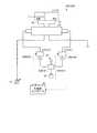
angle detection device 22, but the tilt angle of thebucket 8 is, for example, the stroke length (tilt cylinder length) of thetilt cylinder 30. It is also possible to calculate and acquire from the detected detection result.

[制御システムの構成]
次に、本実施形態に係る制御システム200の概要について説明する。図9は、本実施形態に係る制御システム200の機能構成を示すブロック図である。
[Control system configuration]
Next, an overview of thecontrol system 200 according to the present embodiment will be described. FIG. 9 is a block diagram showing a functional configuration of thecontrol system 200 according to the present embodiment.

制御システム200は、作業機2を用いる掘削処理を制御する。掘削処理の制御は、制限掘削制御を含む。図9に示すように、制御システム200は、位置検出装置20と、角度検出装置22と、チルト角度センサ70と、操作装置25と、作業機コントローラ26と、圧力センサ66と、制御弁27と、方向制御弁64と、表示コントローラ28と、表示部29と、入力部36と、センサコントローラ32と、ポンプコントローラ34と、IMU24とを備えている。  Thecontrol system 200 controls excavation processing using thework machine 2. The control of the excavation process includes limited excavation control. As shown in FIG. 9, thecontrol system 200 includes aposition detection device 20, anangle detection device 22, atilt angle sensor 70, anoperation device 25, awork machine controller 26, apressure sensor 66, and acontrol valve 27. , Adirection control valve 64, adisplay controller 28, adisplay unit 29, aninput unit 36, asensor controller 32, apump controller 34, and anIMU 24.

表示部29は、表示コントローラ28の制御に基づいて、掘削を行うべき目標掘削地形等の所定の情報を表示する。入力部36は、表示部で入力を行うタッチパネル等とされ、オペレータに入力操作される。オペレータに操作されることにより、入力部36は、その操作に基づく操作信号を生成して、表示コントローラ28に出力する。  Thedisplay unit 29 displays predetermined information such as a target excavation landform to be excavated based on the control of thedisplay controller 28. Theinput unit 36 is a touch panel or the like that performs input on the display unit, and is input by an operator. When operated by the operator, theinput unit 36 generates an operation signal based on the operation and outputs the operation signal to thedisplay controller 28.

操作装置25は、運転室4に配置される。オペレータにより操作装置25が操作される。操作装置25は、作業機2を駆動するオペレータ操作を受け付ける。本実施形態において、操作装置25は、パイロット油圧方式の操作装置である。  The operatingdevice 25 is disposed in thecab 4. The operatingdevice 25 is operated by the operator. Theoperation device 25 receives an operator operation for driving thework machine 2. In the present embodiment, the operatingdevice 25 is a pilot hydraulic system operating device.

以下の説明においては、油圧シリンダ(ブームシリンダ10、アームシリンダ11、バケットシリンダ12、及びチルトシリンダ30)を作動するためにその油圧シリンダに供給される油を適宜、作動油、と称する。本実施形態においては、方向制御弁64により、油圧シリンダに対する作動油の供給量が調整される。方向制御弁64は、供給される油によって作動する。以下の説明においては、方向制御弁64を作動するためにその方向制御弁64に供給される油を適宜、パイロット油、と称する。また、パイロット油の圧力を適宜、パイロット油圧、と称する。  In the following description, the oil supplied to the hydraulic cylinders to operate the hydraulic cylinders (theboom cylinder 10, thearm cylinder 11, thebucket cylinder 12, and the tilt cylinder 30) will be appropriately referred to as hydraulic oil. In the present embodiment, thedirectional control valve 64 adjusts the amount of hydraulic oil supplied to the hydraulic cylinder. Thedirection control valve 64 is operated by supplied oil. In the following description, the oil supplied to thedirection control valve 64 in order to operate thedirection control valve 64 is appropriately referred to as pilot oil. The pressure of the pilot oil is appropriately referred to as pilot oil pressure.

作動油及びパイロット油は、同一の油圧ポンプから送出されてもよい。例えば、油圧ポンプから送出された作動油の一部が減圧弁で減圧され、その減圧された作動油がパイロット油として使用されてもよい。また、作動油を送出する油圧ポンプ(メイン油圧ポンプ)と、パイロット油を送出する油圧ポンプ(パイロット油圧ポンプ)とが別の油圧ポンプでもよい。  The hydraulic oil and pilot oil may be delivered from the same hydraulic pump. For example, part of the hydraulic oil sent from the hydraulic pump may be decompressed by a pressure reducing valve, and the decompressed hydraulic oil may be used as pilot oil. In addition, the hydraulic pump that sends hydraulic oil (main hydraulic pump) and the hydraulic pump that sends pilot oil (pilot hydraulic pump) may be different hydraulic pumps.

操作装置25は、第1操作レバー25Rと、第2操作レバー25Lと、第3操作レバー25Pとを有する。第1操作レバー25Rは、例えば運転席4Sの右側に配置される。第2操作レバー25Lは、例えば運転席4Sの左側に配置される。第3操作レバー25Pは、例えば第2操作レバー25Lに配置される。なお、第3操作レバー25Pは、第1操作レバー25Rに配置されてもよい。第1操作レバー25R及び第2操作レバー25Lでは、前後左右の動作が2軸の動作に対応している。  The operatingdevice 25 includes afirst operating lever 25R, asecond operating lever 25L, and athird operating lever 25P. Thefirst operation lever 25R is disposed on the right side of the driver'sseat 4S, for example. Thesecond operation lever 25L is disposed on the left side of the driver'sseat 4S, for example. Thethird operation lever 25P is disposed, for example, on thesecond operation lever 25L. Note that thethird operation lever 25P may be disposed on thefirst operation lever 25R. In thefirst operation lever 25R and thesecond operation lever 25L, the front / rear and left / right operations correspond to the biaxial operations.

第1操作レバー25Rにより、ブーム6及びバケット8が操作される。第1操作レバー25Rの前後方向の操作は、ブーム6の操作に対応し、前後方向の操作に応じてブーム6の下げ動作及び上げ動作が実行される。第1操作レバー25Rの左右方向の操作は、バケット8の操作に対応し、左右方向の操作に応じてバケット8の掘削動作及び開放動作が実行される。  The boom 6 and thebucket 8 are operated by thefirst operation lever 25R. The operation in the front-rear direction of thefirst operation lever 25R corresponds to the operation of the boom 6, and the lowering operation and the raising operation of the boom 6 are executed according to the operation in the front-rear direction. The operation in the left-right direction of thefirst operation lever 25R corresponds to the operation of thebucket 8, and the excavation operation and the opening operation of thebucket 8 are executed according to the operation in the left-right direction.

第2操作レバー25Lにより、アーム7及び旋回体3が操作される。第2操作レバー25Lの前後方向の操作は、アーム7の操作に対応し、前後方向の操作に応じてアーム7の上げ動作及び下げ動作が実行される。第2操作レバー25Lの左右方向の操作は、旋回体3の旋回に対応し、左右方向の操作に応じて旋回体3の右旋回動作及び左旋回動作が実行される。  Thearm 7 and the swing body 3 are operated by thesecond operation lever 25L. The operation in the front-rear direction of thesecond operation lever 25L corresponds to the operation of thearm 7, and the raising operation and the lowering operation of thearm 7 are executed according to the operation in the front-rear direction. The left / right operation of thesecond operation lever 25L corresponds to the turning of the revolving structure 3, and the right turning operation and the left turning operation of the revolving structure 3 are executed according to the left / right operation.

第3操作レバー25Pにより、バケット8が操作される。本実施形態においては、第1操作レバー25Rにより、バケット軸J3を中心とするバケット8の回転が操作される。第3操作レバー25Pにより、チルト軸J4を中心とするバケット8の回転(チルト)が操作される。  Thebucket 8 is operated by thethird operation lever 25P. In the present embodiment, the rotation of thebucket 8 about the bucket shaft J3 is operated by thefirst operation lever 25R. The rotation (tilt) of thebucket 8 about the tilt axis J4 is operated by thethird operation lever 25P.

本実施形態において、ブーム6の上げ動作は、ダンプ動作に相当する。ブーム6の下げ動作は、掘削動作に相当する。アーム7の下げ動作は、掘削動作に相当する。アーム7の上げ動作は、ダンプ動作に相当する。バケット8の下げ動作は、掘削動作に相当する。なお、アーム7の下げ動作を曲げ動作と称してもよい。アーム7の上げ動作を伸長動作と称してもよい。  In the present embodiment, the raising operation of the boom 6 corresponds to a dumping operation. The lowering operation of the boom 6 corresponds to an excavation operation. The lowering operation of thearm 7 corresponds to an excavation operation. The raising operation of thearm 7 corresponds to a dumping operation. The lowering operation of thebucket 8 corresponds to an excavation operation. The lowering operation of thearm 7 may be referred to as a bending operation. The raising operation of thearm 7 may be referred to as an extension operation.

パイロット油圧ポンプから送出され、制御弁によってパイロット油圧に減圧されたパイロット油が操作装置25に供給される。操作装置25の操作量に基づいてパイロット油圧が調整され、そのパイロット油圧に応じて、油圧シリンダ(ブームシリンダ10、アームシリンダ11、バケットシリンダ12、及びチルトシリンダ40)に供給される作動油が流れる方向制御弁64が駆動される。パイロット油圧ライン450には、圧力センサ66が配置されている。圧力センサ66は、パイロット油圧を検出する。圧力センサ66の検出結果は、作業機コントローラ26に出力される。  Pilot oil sent from the pilot hydraulic pump and decompressed to the pilot hydraulic pressure by the control valve is supplied to the operatingdevice 25. The pilot oil pressure is adjusted based on the operation amount of the operatingdevice 25, and the hydraulic oil supplied to the hydraulic cylinders (theboom cylinder 10, thearm cylinder 11, thebucket cylinder 12, and the tilt cylinder 40) flows according to the pilot oil pressure. Thedirection control valve 64 is driven. Apressure sensor 66 is disposed in the pilothydraulic line 450. Thepressure sensor 66 detects pilot oil pressure. The detection result of thepressure sensor 66 is output to thework machine controller 26.

第1操作レバー25Rは、ブーム6の駆動のために前後方向に操作される。前後方向に関する第1操作レバー25Rの操作量(ブーム操作量)に応じて、ブーム6を駆動するためのブームシリンダ10に供給される作動油が流れる方向制御弁64が駆動される。  Thefirst operation lever 25 </ b> R is operated in the front-rear direction for driving the boom 6. Thedirection control valve 64 through which hydraulic oil supplied to theboom cylinder 10 for driving the boom 6 flows is driven according to the operation amount (boom operation amount) of thefirst operation lever 25R in the front-rear direction.

第1操作レバー25Rは、バケット8の駆動のために左右方向に操作される。左右方向に関する第1操作レバー25Rの操作量(バケット操作量)に応じて、バケット8を駆動するためのバケットシリンダ12に供給される作動油が流れる方向制御弁64が駆動される。  Thefirst operation lever 25 </ b> R is operated in the left-right direction for driving thebucket 8. Thedirection control valve 64 in which the hydraulic oil supplied to thebucket cylinder 12 for driving thebucket 8 flows is driven according to the operation amount (bucket operation amount) of thefirst operation lever 25R in the left-right direction.

第2操作レバー25Lは、アーム7の駆動のために前後方向に操作される。前後方向に関する第2操作レバー25Lの操作量(アーム操作量)に応じて、アーム7を駆動するためのアームシリンダ11に供給される作動油が流れる方向制御弁64が駆動される。  Thesecond operation lever 25L is operated in the front-rear direction for driving thearm 7. Thedirection control valve 64 through which hydraulic oil supplied to thearm cylinder 11 for driving thearm 7 flows is driven according to the operation amount (arm operation amount) of thesecond operation lever 25L in the front-rear direction.

第2操作レバー25Lは、旋回体3の駆動のために左右方向に操作される。左右方向に関する第2操作レバー25Lの操作量に応じて、旋回体3を駆動するための油圧アクチュエータに供給される作動油が流れる方向制御弁64が駆動される。  Thesecond operation lever 25L is operated in the left-right direction for driving the revolving structure 3. In accordance with the operation amount of thesecond operation lever 25L in the left-right direction, thedirection control valve 64 through which hydraulic oil supplied to the hydraulic actuator for driving the revolving structure 3 flows is driven.

第3操作レバー25Pは、バケット8の駆動(チルト軸J4を中心とする回転)のために操作される。第3操作レバー25Pの操作量に応じて、バケット8をチルトさせるためのチルトシリンダ30に供給される作動油が流れる方向制御弁64が駆動される。  Thethird operation lever 25P is operated for driving the bucket 8 (rotation about the tilt axis J4). Thedirection control valve 64 through which the hydraulic oil supplied to thetilt cylinder 30 for tilting thebucket 8 flows is driven according to the operation amount of thethird operation lever 25P.

なお、第1操作レバー25Rの左右方向の操作がブーム6の操作に対応し、前後方向の操作がバケット8の操作に対応してもよい。なお、第2操作レバー25Lの左右方向がアーム7の操作に対応し、前後方向の操作が旋回体3の操作に対応してもよい。  The left / right operation of thefirst operation lever 25R may correspond to the operation of the boom 6 and the front / rear operation may correspond to the operation of thebucket 8. The left / right direction of thesecond operation lever 25L may correspond to the operation of thearm 7 and the operation in the front / rear direction may correspond to the operation of the revolving structure 3.

制御弁27は、油圧シリンダ(ブームシリンダ10、アームシリンダ11、バケットシリンダ12、及びチルトシリンダ30)に対する作動油の供給量を調整するために作動する。制御弁27は、作業機コントローラ26からの制御信号に基づいて作動する。  Thecontrol valve 27 operates to adjust the amount of hydraulic oil supplied to the hydraulic cylinders (theboom cylinder 10, thearm cylinder 11, thebucket cylinder 12, and the tilt cylinder 30). Thecontrol valve 27 operates based on a control signal from thework machine controller 26.

角度検出装置22は、ブーム軸J1を中心とするブーム6の回転角度αを示すブーム角度データ、アーム軸J2を中心とするアーム7の回転角度βを示すアーム角度データ、及びバケット軸J3を中心とするバケット8の回転角度γを示すバケット角度データを含む作業機角度データを検出する。  Theangle detection device 22 has boom angle data indicating the rotation angle α of the boom 6 centered on the boom axis J1, arm angle data indicating the rotation angle β of thearm 7 centered on the arm axis J2, and the bucket axis J3. Working machine angle data including bucket angle data indicating the rotation angle γ of thebucket 8 is detected.

本実施形態において、角度検出装置22は、第1ストロークセンサ16、第2ストロークセンサ17、及び第3ストロークセンサ18を含む。第1ストロークセンサ16の検出結果、第2ストロークセンサ17の検出結果、及び第3ストロークセンサ18の検出結果がセンサコントローラ32に出力される。センサコントローラ32は、第1ストロークセンサ16の検出結果に基づいて、ブームシリンダ長を算出する。第1ストロークセンサ16は、周回動作に伴う位相変位のパルスをセンサコントローラ32に出力する。センサコントローラ32は、第1ストロークセンサ16から出力された位相変位のパルスに基づいて、ブームシリンダ長を算出する。同様に、センサコントローラ32は、第2ストロークセンサ17の検出結果に基づいて、アームシリンダ長を算出する。センサコントローラ32は、第3ストロークセンサ18の検出結果に基づいて、バケットシリンダ長を算出する。  In the present embodiment, theangle detection device 22 includes afirst stroke sensor 16, asecond stroke sensor 17, and athird stroke sensor 18. The detection result of thefirst stroke sensor 16, the detection result of thesecond stroke sensor 17, and the detection result of thethird stroke sensor 18 are output to thesensor controller 32. Thesensor controller 32 calculates the boom cylinder length based on the detection result of thefirst stroke sensor 16. Thefirst stroke sensor 16 outputs to the sensor controller 32 a pulse of phase displacement associated with the orbiting operation. Thesensor controller 32 calculates the boom cylinder length based on the phase displacement pulse output from thefirst stroke sensor 16. Similarly, thesensor controller 32 calculates the arm cylinder length based on the detection result of thesecond stroke sensor 17. Thesensor controller 32 calculates the bucket cylinder length based on the detection result of thethird stroke sensor 18.

センサコントローラ32は、第1ストロークセンサ16の検出結果に基づいて取得されたブームシリンダ長から、車両本体1の垂直方向に対するブーム6の回転角度αを算出する。センサコントローラ32は、第2ストロークセンサ17の検出結果に基づいて取得されたアームシリンダ長から、ブーム6に対するアーム7の回転角度βを算出する。センサコントローラ32は、第3ストロークセンサ18の検出結果に基づいて取得されたバケットシリンダ長から、アーム7に対するバケット8の刃先8aの回転角度γを算出する。  Thesensor controller 32 calculates the rotation angle α of the boom 6 with respect to the vertical direction of the vehicle main body 1 from the boom cylinder length acquired based on the detection result of thefirst stroke sensor 16. Thesensor controller 32 calculates the rotation angle β of thearm 7 with respect to the boom 6 from the arm cylinder length acquired based on the detection result of thesecond stroke sensor 17. Thesensor controller 32 calculates the rotation angle γ of theblade edge 8 a of thebucket 8 with respect to thearm 7 from the bucket cylinder length acquired based on the detection result of thethird stroke sensor 18.

なお、ブーム6の回転角度α、アーム7の回転角度β、及びバケット8の回転角度γは、ストロークセンサで検出されなくてもよい。ロータリーエンコーダのような角度検出器でブーム6の回転角度αが検出されてもよい。角度検出器は、旋回体3に対するブーム6の屈曲角度を検出して、回転角度αを検出する。同様に、アーム7の回転角度βがアーム7に取り付けられた角度検出器で検出されてもよい。バケット8の回転角度γがバケット8に取り付けられた角度検出器で検出されてもよい。  Note that the rotation angle α of the boom 6, the rotation angle β of thearm 7, and the rotation angle γ of thebucket 8 may not be detected by the stroke sensor. The rotation angle α of the boom 6 may be detected by an angle detector such as a rotary encoder. The angle detector detects the bending angle of the boom 6 with respect to the revolving structure 3 and detects the rotation angle α. Similarly, the rotation angle β of thearm 7 may be detected by an angle detector attached to thearm 7. The rotation angle γ of thebucket 8 may be detected by an angle detector attached to thebucket 8.

センサコントローラ32は、第1、第2、第3ストロークセンサ16、17、18からシリンダ長データL及び作業機角度データを取得する。センサコントローラ32は、作業機回転角度データα〜γを表示コントローラ28及び作業機コントローラ26のそれぞれに出力する。  Thesensor controller 32 acquires cylinder length data L and work implement angle data from the first, second, andthird stroke sensors 16, 17, and 18. Thesensor controller 32 outputs work implement rotation angle data α to γ to thedisplay controller 28 and the work implementcontroller 26, respectively.

表示コントローラ28は、位置検出装置20から車両本体位置データP及び車両本体姿勢データQを取得する。また、表示コントローラ28は、チルト角度センサ70からチルト角度δを示すチルト角度データを取得する。  Thedisplay controller 28 acquires vehicle body position data P and vehicle body posture data Q from theposition detection device 20. Further, thedisplay controller 28 acquires tilt angle data indicating the tilt angle δ from thetilt angle sensor 70.

表示コントローラ28は、演算処理を行う演算部280Aと、データが記憶される記憶部280Bと、データを取得する取得部280Cとを有する。  Thedisplay controller 28 includes acalculation unit 280A that performs calculation processing, astorage unit 280B that stores data, and anacquisition unit 280C that acquires data.

表示コントローラ28は、記憶する目標施工情報、各作業機の寸法、車両本体位置データP、車両本体姿勢データQ、及び各作業機の回転角度データα〜γに基づいて、目標掘削地形データUを算出し、作業機コントローラ26へ出力する。  Thedisplay controller 28 stores the target excavation landform data U based on the stored target construction information, the dimensions of each work machine, the vehicle body position data P, the vehicle body attitude data Q, and the rotation angle data α to γ of each work machine. Calculate and output to thework machine controller 26.

作業機コントローラ26は、作業機制御部26Aと、記憶部26Cとを有する。作業機コントローラ26は表示コントローラ28から、目標掘削地形データUを受け取り、センサコントローラ32から各作業機の回転角度データα〜γを取得する。作業機コントローラ26は、目標掘削地形データU、及び作業機の回転角度データα〜γ基づいて、制御弁27への制御指令を生成する。また作業機コントローラ26はポンプコントローラ34へチルトバケットを使用する時の操作指令を行う。  Thework machine controller 26 includes a workmachine control unit 26A and astorage unit 26C. Thework machine controller 26 receives the target excavation landform data U from thedisplay controller 28 and acquires the rotation angle data α to γ of each work machine from thesensor controller 32. Thework machine controller 26 generates a control command to thecontrol valve 27 based on the target excavation landform data U and the rotation angle data α to γ of the work machine. Further, thework machine controller 26 issues an operation command to thepump controller 34 when using the tilt bucket.

ポンプコントローラ34は、作業機2へ作動油を供給する油圧ポンプ41への駆動指令を行う。また、ポンプコントローラ34は、バケット8のチルト角度を操作する為に後述する制御弁27D、27Eへ指令を行う。The
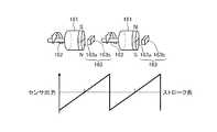
pump controller 34 issues a drive command to thehydraulic pump 41 that supplies hydraulic oil to thework machine 2. In addition, thepump controller 34 gives a command to controlvalves 27D and 27E, which will be described later, in order to manipulate the tilt angle of thebucket 8.

[ストロークセンサ]
次に、図10及び図11を参照して、ストロークセンサ16について説明する。以下の説明においては、ブームシリンダ10に取り付けられたストロークセンサ16について説明する。アームシリンダ11に取付けられたストロークセンサ17なども同様である。
[Stroke sensor]
Next, thestroke sensor 16 will be described with reference to FIGS. 10 and 11. In the following description, thestroke sensor 16 attached to theboom cylinder 10 will be described. The same applies to thestroke sensor 17 attached to thearm cylinder 11.

ブームシリンダ10には、ストロークセンサ16が取り付けられている。ストロークセンサ16は、ピストンのストロークを計測する。図10に示すように、ブームシリンダ10は、シリンダチューブ10Xと、シリンダチューブ10X内においてシリンダチューブ10Xに対して相対的に移動可能なシリンダロッド10Yとを有する。シリンダチューブ10Xには、ピストン10Vが摺動自在に設けられている。ピストン10Vには、シリンダロッド10Yが取り付けられている。シリンダロッド10Yは、シリンダヘッド10Wに摺動自在に設けられている。シリンダヘッド10Wとピストン10Vとシリンダ内壁とによって画成された室は、ロッド側油室40Bである。ピストン10Vを介してロッド側油室40Bとは反対側の油室がキャップ側油室40Aである。なお、シリンダヘッド10Wには、シリンダロッド10Yとの隙間を密封し、塵埃等がロッド側油室40Bに入り込まないようにするシール部材が設けられている。  Astroke sensor 16 is attached to theboom cylinder 10. Thestroke sensor 16 measures the stroke of the piston. As shown in FIG. 10, theboom cylinder 10 includes acylinder tube 10X and acylinder rod 10Y that can move relative to thecylinder tube 10X in thecylinder tube 10X. Apiston 10V is slidably provided on thecylinder tube 10X. Acylinder rod 10Y is attached to thepiston 10V. Thecylinder rod 10Y is slidably provided on thecylinder head 10W. A chamber defined by thecylinder head 10W, thepiston 10V, and the cylinder inner wall is a rod-side oil chamber 40B. An oil chamber opposite to the rod-side oil chamber 40B via thepiston 10V is a cap-side oil chamber 40A. Thecylinder head 10W is provided with a seal member that seals the gap with thecylinder rod 10Y and prevents dust and the like from entering the rod-side oil chamber 40B.

シリンダロッド10Yは、ロッド側油室40Bに作動油が供給され、キャップ側油室40Aから作動油が排出されることによって縮退する。また、シリンダロッド10Yは、ロッド側油室40Bから作動油が排出され、キャップ側油室40Aに作動油が供給されることによって伸張する。すなわち、シリンダロッド10Yは、図中左右方向に直動する。  Thecylinder rod 10Y is degenerated when hydraulic oil is supplied to the rod-side oil chamber 40B and discharged from the cap-side oil chamber 40A. Further, thecylinder rod 10Y extends when the hydraulic oil is discharged from the rod-side oil chamber 40B and the hydraulic oil is supplied to the cap-side oil chamber 40A. That is, thecylinder rod 10Y moves linearly in the left-right direction in the figure.

ロッド側油室40Bの外部にあって、シリンダヘッド10Wに密接した場所には、ストロークセンサ16を覆い、ストロークセンサ16を内部に収容するケース164が設けられている。ケース164は、シリンダヘッド10Wにボルト等によって締結等されて、シリンダヘッド10Wに固定されている。  Acase 164 that covers thestroke sensor 16 and accommodates thestroke sensor 16 therein is provided outside the rod-side oil chamber 40B and in close contact with thecylinder head 10W. Thecase 164 is fastened to thecylinder head 10W by a bolt or the like and fixed to thecylinder head 10W.

ストロークセンサ16は、回転ローラ161と、回転中心軸162と、回転センサ部163とを有している。回転ローラ161は、その表面がシリンダロッド10Yの表面に接触し、シリンダロッド10Yの直動に応じて回転自在に設けられている。すなわち、回転ローラ161によってシリンダロッド10Yの直線運動が回転運動に変換される。回転中心軸162は、シリンダロッド10Yの直動方向に対して、直交するように配置されている。  Thestroke sensor 16 includes arotation roller 161, arotation center shaft 162, and arotation sensor unit 163. The surface of therotating roller 161 is in contact with the surface of thecylinder rod 10Y, and is rotatably provided according to the direct movement of thecylinder rod 10Y. That is, the linear motion of thecylinder rod 10Y is converted into rotational motion by therotating roller 161. Therotation center shaft 162 is disposed so as to be orthogonal to the linear movement direction of thecylinder rod 10Y.

回転センサ部163は、回転ローラ161の回転量(回転角度)を電気信号として検出可能に構成されている。回転センサ部163で検出された回転ローラ161の回転量(回転角度)を示す信号は、電気信号線を介して、センサコントローラ32に送られ、この作業機コントローラ26でブームシリンダ10のシリンダロッド10Yの位置(ストローク位置)に変換される。  Therotation sensor unit 163 is configured to be able to detect the rotation amount (rotation angle) of therotation roller 161 as an electrical signal. A signal indicating the rotation amount (rotation angle) of therotation roller 161 detected by therotation sensor unit 163 is sent to thesensor controller 32 via the electric signal line, and thework machine controller 26 uses thecylinder rod 10Y of theboom cylinder 10 to transmit the signal. It is converted to the position (stroke position).

図11に示すように、回転センサ部163は、磁石163aと、ホールIC163bとを有している。検出媒体である磁石163aは、回転ローラ161と一体に回転するように回転ローラ161に取り付けられている。磁石163aは回転中心軸162を中心とした回転ローラ161の回転に応じて回転する。磁石163aは、回転ローラ161の回転角度に応じて、N極、S極が交互に入れ替わるように構成されている。磁石163aは、回転ローラ161の一回転を一周期として、ホールIC163bで検出される磁力(磁束密度)が周期的に変動するように構成されている。  As shown in FIG. 11, therotation sensor unit 163 includes amagnet 163a and aHall IC 163b. Amagnet 163a as a detection medium is attached to therotating roller 161 so as to rotate integrally with therotating roller 161. Themagnet 163a rotates in accordance with the rotation of therotating roller 161 about therotation center shaft 162. Themagnet 163a is configured such that the N pole and the S pole are alternately switched according to the rotation angle of therotating roller 161. Themagnet 163a is configured such that the magnetic force (magnetic flux density) detected by theHall IC 163b periodically varies with one rotation of therotating roller 161 as one cycle.

ホールIC163bは、磁石163aによって生成される磁力(磁束密度)を電気信号として検出する磁力センサである。ホールIC163bは、回転中心軸162の軸方向に沿って、磁石163aから所定距離、離間された位置に設けられている。  TheHall IC 163b is a magnetic force sensor that detects a magnetic force (magnetic flux density) generated by themagnet 163a as an electric signal. TheHall IC 163b is provided at a position separated from themagnet 163a by a predetermined distance along the axial direction of therotation center shaft 162.

ホールIC163bで検出された電気信号は、作業機コントローラ26に送られ、この作業機コントローラ26で、ホールIC163bの電気信号が、回転ローラ161の回転量、つまりブームシリンダ10のシリンダロッド10Yの変位量(ストローク長)に変換される。  The electric signal detected by theHall IC 163b is sent to thework machine controller 26, and the electric signal of theHall IC 163b is sent from thework machine controller 26 to the rotation amount of therotating roller 161, that is, the displacement amount of thecylinder rod 10Y of theboom cylinder 10. Converted to (stroke length).

ここで、図11を参照して、回転ローラ161の回転角度と、ホールIC163bで検出される電気信号(電圧)との関係を説明する。回転ローラ161が回転し、その回転に応じて磁石163aが回転すると、回転角度に応じて、ホールIC163bを透過する磁力(磁束密度)が周期的に変化し、センサ出力である電気信号(電圧)が周期的に変化する。このホールIC163bから出力される電圧の大きさから回転ローラ161の回転角度を計測することができる。  Here, with reference to FIG. 11, the relationship between the rotation angle of therotating roller 161 and the electrical signal (voltage) detected by theHall IC 163b will be described. When therotating roller 161 rotates and themagnet 163a rotates according to the rotation, the magnetic force (magnetic flux density) transmitted through theHall IC 163b periodically changes according to the rotation angle, and an electric signal (voltage) that is a sensor output. Changes periodically. The rotation angle of therotating roller 161 can be measured from the magnitude of the voltage output from theHall IC 163b.

また、ホールIC163bから出力される電気信号(電圧)の1周期が繰り返される数をカウントすることで、回転ローラ161の回転数を計測することができる。そして、回転ローラ161の回転角度と、回転ローラ161の回転数とに基づいて、ブームシリンダ10のシリンダロッド10Yの変位量(ストローク長)が検出される。  In addition, the number of rotations of therotating roller 161 can be measured by counting the number of times one cycle of the electrical signal (voltage) output from theHall IC 163b is repeated. The displacement amount (stroke length) of thecylinder rod 10Y of theboom cylinder 10 is detected based on the rotation angle of therotation roller 161 and the rotation speed of therotation roller 161.

また、ストロークセンサ16は、回転ローラ161の回転角度と、回転ローラ161の回転数とに基づいて、シリンダロッド10Yの移動速度(シリンダ速度)を検出することができる。  Thestroke sensor 16 can detect the moving speed (cylinder speed) of thecylinder rod 10Y based on the rotation angle of therotating roller 161 and the rotation speed of therotating roller 161.

[油圧システム]
次に、本実施形態に係る油圧システム300の一例について説明する。制御システム200は、油圧システム300と、作業機コントローラ26とを含む。ブームシリンダ10、アームシリンダ11、バケットシリンダ12、及びチルトシリンダ30のそれぞれは、油圧シリンダである。それら油圧シリンダは、油圧システム300により作動する。
[Hydraulic system]
Next, an example of thehydraulic system 300 according to the present embodiment will be described. Thecontrol system 200 includes ahydraulic system 300 and awork machine controller 26. Each of theboom cylinder 10, thearm cylinder 11, thebucket cylinder 12, and thetilt cylinder 30 is a hydraulic cylinder. These hydraulic cylinders are operated by ahydraulic system 300.

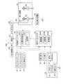
図13は、アームシリンダ11を含む油圧システム300の一例を模式的に示す図である。なお、バケットシリンダ12も同様である。油圧システム300は、方向制御弁64を介してアームシリンダ11に作動油を供給する可変容量型のメイン油圧ポンプ41と、パイロット油を供給するパイロット油圧ポンプ42と、方向制御弁64に対するパイロット油のパイロット油圧を調整する操作装置25と、パイロット油が流れる油路43(43A、43B)と、油路43に配置された制御弁27(27A、27B)と、油路43に配置された圧力センサ66(66A、66B)と、制御弁27を制御する作業機コントローラ26とを備えている。油路43は、図9におけるパイロット油圧ライン450と同じである。  FIG. 13 is a diagram schematically illustrating an example of ahydraulic system 300 including thearm cylinder 11. The same applies to thebucket cylinder 12. Thehydraulic system 300 includes a variable displacement mainhydraulic pump 41 that supplies hydraulic oil to thearm cylinder 11 via thedirection control valve 64, a pilothydraulic pump 42 that supplies pilot oil, and pilot oil for thedirection control valve 64. An operatingdevice 25 for adjusting the pilot oil pressure, an oil passage 43 (43A, 43B) through which pilot oil flows, a control valve 27 (27A, 27B) disposed in theoil passage 43, and a pressure sensor disposed in theoil passage 43 66 (66A, 66B) and awork machine controller 26 for controlling thecontrol valve 27. Theoil passage 43 is the same as the pilothydraulic line 450 in FIG.

方向制御弁64は、作動油が流れる方向を制御する。メイン油圧ポンプ41から供給された作動油は、方向制御弁64を介して、アームシリンダ11に供給される。方向制御弁64は、ロッド状のスプールを動かして作動油が流れる方向を切り替えるスプール方式である。スプールが軸方向に移動することにより、アームシリンダ11のキャップ側油室40A(油路47)に対する作動油の供給と、ロッド側油室40B(油路48)に対する作動油の供給とが切り替わる。また、スプールが軸方向に移動することにより、アームシリンダ11に対する作動油の供給量(単位時間当たりの供給量)が調整される。アームシリンダ11に対する作動油の供給量が調整されることにより、シリンダ速度が調整される。  Thedirection control valve 64 controls the direction in which the hydraulic oil flows. The hydraulic oil supplied from the mainhydraulic pump 41 is supplied to thearm cylinder 11 via thedirection control valve 64. Thedirection control valve 64 is a spool system that moves the rod-shaped spool to switch the direction in which the hydraulic oil flows. When the spool moves in the axial direction, the supply of hydraulic oil to the capside oil chamber 40A (oil passage 47) of thearm cylinder 11 and the supply of hydraulic oil to the rodside oil chamber 40B (oil passage 48) are switched. Further, the supply amount of hydraulic oil (supply amount per unit time) to thearm cylinder 11 is adjusted by moving the spool in the axial direction. The cylinder speed is adjusted by adjusting the amount of hydraulic oil supplied to thearm cylinder 11.

方向制御弁64の駆動は、操作装置25によって調整される。本実施形態において、操作装置25は、パイロット油圧方式の操作装置である。パイロット油圧ポンプ42から送出されたパイロット油が操作装置25に供給される。なお、メイン油圧ポンプ41から送出され、減圧弁によって減圧されたパイロット油が操作装置25に供給されてもよい。操作装置25は、パイロット油圧調整弁を含む。操作装置25の操作量に基づいて、パイロット油圧が調整される。そのパイロット油圧によって、方向制御弁64が駆動される。操作装置25によりパイロット油圧が調整されることによって、軸方向に関するスプールの移動量及び移動速度が調整される。  The driving of thedirection control valve 64 is adjusted by theoperation device 25. In the present embodiment, the operatingdevice 25 is a pilot hydraulic system operating device. Pilot oil delivered from the pilothydraulic pump 42 is supplied to the operatingdevice 25. Note that pilot oil sent from the mainhydraulic pump 41 and decompressed by the pressure reducing valve may be supplied to the operatingdevice 25. The operatingdevice 25 includes a pilot hydraulic pressure adjustment valve. The pilot oil pressure is adjusted based on the operation amount of the operatingdevice 25. Thedirection control valve 64 is driven by the pilot hydraulic pressure. By adjusting the pilot oil pressure by the operatingdevice 25, the moving amount and moving speed of the spool in the axial direction are adjusted.

パイロット油が流れる油路43は、1つの方向制御弁64に対して2つ設けられる。2つの油路43A及び油路43Bのうち、一方の油路43Aには、方向制御弁64のスプールの一方の空間(第1受圧室)に供給されるパイロット油が流れる。他方の油路43Bには、方向制御弁64のスプールの他方の空間(第2受圧室)に供給されるパイロット油が流れる。  Twooil passages 43 through which pilot oil flows are provided for onedirectional control valve 64. Of the twooil passages 43A and 43B, the pilot oil supplied to one space (first pressure receiving chamber) of the spool of thedirection control valve 64 flows into oneoil passage 43A. Pilot oil supplied to the other space (second pressure receiving chamber) of the spool of thedirection control valve 64 flows through theother oil passage 43B.

油路43に圧力センサ66が配置される。圧力センサ66は、パイロット油圧を検出する。圧力センサ66は、油路43Aのパイロット油圧を検出する圧力センサ66Aと、油路43Bのパイロット油圧を検出する圧力センサ66Bとを含む。圧力センサ66の検出結果は、作業機コントローラ26に出力される。  Apressure sensor 66 is disposed in theoil passage 43. Thepressure sensor 66 detects pilot oil pressure. Thepressure sensor 66 includes apressure sensor 66A that detects the pilot oil pressure in theoil passage 43A, and apressure sensor 66B that detects the pilot oil pressure in theoil passage 43B. The detection result of thepressure sensor 66 is output to thework machine controller 26.

制御弁27は、電磁比例制御弁であり、作業機コントローラ26からの制御信号に基づいて、パイロット油圧を調整可能である。制御弁27は、油路43Aのパイロット油圧を調整可能な制御弁27Aと、油路43Bのパイロット油圧を調整可能な制御弁27Bとを含む。  Thecontrol valve 27 is an electromagnetic proportional control valve, and can adjust the pilot hydraulic pressure based on a control signal from thework machine controller 26. Thecontrol valve 27 includes acontrol valve 27A that can adjust the pilot oil pressure of theoil passage 43A, and acontrol valve 27B that can adjust the pilot oil pressure of theoil passage 43B.

操作装置25の操作によってパイロット油圧を調整する場合、制御弁27は全開にされる。操作装置25の操作レバーが中立位置より一側に動かされると、その操作レバーの操作量に応じたパイロット油圧が方向制御弁64のスプールの第1受圧室に作用する。操作装置25の操作レバーが中立位置より他側に動かされると、その操作レバーの操作量に応じたパイロット油圧が方向制御弁64のスプールの第2受圧室に作用する。  When the pilot hydraulic pressure is adjusted by operating the operatingdevice 25, thecontrol valve 27 is fully opened. When the operation lever of theoperation device 25 is moved to one side from the neutral position, pilot hydraulic pressure corresponding to the operation amount of the operation lever acts on the first pressure receiving chamber of the spool of thedirection control valve 64. When the operating lever of the operatingdevice 25 is moved from the neutral position to the other side, the pilot hydraulic pressure corresponding to the operating amount of the operating lever acts on the second pressure receiving chamber of the spool of thedirection control valve 64.

方向制御弁64のスプールは、操作装置25によって調整されたパイロット油圧に応じた距離だけ動く。例えば、第1受圧室にパイロット油圧が作用することにより、アームシリンダ11のキャップ側油室40Aにメイン油圧ポンプ41からの作動油が供給され、アームシリンダ11が伸びる。第2受圧室にパイロット油圧が作用することにより、アームシリンダ11のロッド側油室40Bに、メイン油圧ポンプ41からの作動油が供給され、アームシリンダ11が縮む。方向制御弁64のスプールの移動量に基づいて、メイン油圧ポンプ41から方向制御弁64を介してアームシリンダ11に供給される単位時間当たりの作動油の供給量が調整される。単位時間当たりの作動油の供給量が調整されることによって、シリンダ速度が調整される。  The spool of thedirection control valve 64 moves by a distance corresponding to the pilot hydraulic pressure adjusted by the operatingdevice 25. For example, when the pilot oil pressure acts on the first pressure receiving chamber, the hydraulic oil from the mainhydraulic pump 41 is supplied to the capside oil chamber 40A of thearm cylinder 11 and thearm cylinder 11 extends. When the pilot hydraulic pressure acts on the second pressure receiving chamber, the hydraulic oil from the mainhydraulic pump 41 is supplied to the rodside oil chamber 40B of thearm cylinder 11 and thearm cylinder 11 is contracted. Based on the amount of movement of the spool of thedirection control valve 64, the amount of hydraulic oil supplied per unit time supplied from the mainhydraulic pump 41 to thearm cylinder 11 via thedirection control valve 64 is adjusted. The cylinder speed is adjusted by adjusting the amount of hydraulic oil supplied per unit time.

作業機コントローラ26は、制御弁27を制御して、パイロット油圧を調整可能である。例えば、制限掘削制御(介入制御)において、作業機コントローラ26は、制御弁27を駆動する。例えば、作業機コントローラ26によって制御弁27Aが駆動されることにより、方向制御弁64のスプールが、制御弁27Aによって調整されたパイロット油圧に応じた距離だけ動く。これにより、アームシリンダ11のキャップ側油室40Aにメイン油圧ポンプ41からの作動油が供給され、アームシリンダ11が伸びる。作業機コントローラ26によって制御弁27Bが駆動されることにより、方向制御弁64のスプールが、制御弁27Bによって調整されたパイロット油圧に応じた距離だけ動く。これにより、アームシリンダ11のロッド側油室40Bに、メイン油圧ポンプ41からの作動油が供給され、アームシリンダ11が縮む。方向制御弁64のスプールの移動量に基づいて、メイン油圧ポンプ41から方向制御弁64を介してアームシリンダ11に供給される単位時間当たりの作動油の供給量が調整される。単位時間当たりの作動油の供給量が調整されることによって、シリンダ速度が調整される。  Thework machine controller 26 can adjust the pilot hydraulic pressure by controlling thecontrol valve 27. For example, in the limited excavation control (intervention control), thework machine controller 26 drives thecontrol valve 27. For example, when thecontrol valve 27A is driven by thework machine controller 26, the spool of thedirectional control valve 64 moves by a distance corresponding to the pilot hydraulic pressure adjusted by thecontrol valve 27A. As a result, hydraulic oil from the mainhydraulic pump 41 is supplied to the cap-side oil chamber 40A of thearm cylinder 11, and thearm cylinder 11 extends. When thecontrol valve 27B is driven by thework machine controller 26, the spool of thedirectional control valve 64 moves by a distance corresponding to the pilot hydraulic pressure adjusted by thecontrol valve 27B. As a result, the hydraulic oil from the mainhydraulic pump 41 is supplied to the rodside oil chamber 40B of thearm cylinder 11, and thearm cylinder 11 contracts. Based on the amount of movement of the spool of thedirection control valve 64, the amount of hydraulic oil supplied per unit time supplied from the mainhydraulic pump 41 to thearm cylinder 11 via thedirection control valve 64 is adjusted. The cylinder speed is adjusted by adjusting the amount of hydraulic oil supplied per unit time.

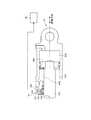
図14は、ブームシリンダ10を含む油圧システム300の一例を模式的に示す図である。操作装置25の操作により、ブーム6は、下げ動作及び上げ動作の2種類の動作を実行する。図13を参照して説明したように、操作装置25が操作されることにより、操作装置25の操作量に応じたパイロット油圧が方向制御弁64に作用する。方向制御弁64のスプールは、パイロット油圧に応じて移動する。スプールの移動量に基づいて、メイン油圧ポンプ41から方向制御弁64を介してブームシリンダ10に供給される単位時間当たりの作動油の供給量が調整される。  FIG. 14 is a diagram schematically illustrating an example of ahydraulic system 300 including theboom cylinder 10. By operating the operatingdevice 25, the boom 6 performs two types of operations, a lowering operation and a raising operation. As described with reference to FIG. 13, when theoperation device 25 is operated, the pilot hydraulic pressure corresponding to the operation amount of theoperation device 25 acts on thedirection control valve 64. The spool of thedirection control valve 64 moves according to the pilot hydraulic pressure. Based on the amount of movement of the spool, the amount of hydraulic oil supplied per unit time supplied from the mainhydraulic pump 41 to theboom cylinder 10 via thedirection control valve 64 is adjusted.

また、作業機コントローラ26は、制御弁27Aを駆動して、第2受圧室に作用するパイロット油圧を調整可能である。作業機コントローラ26は、制御弁27Bを駆動して、第1受圧室に作用するパイロット油圧を調整可能である。図14に示す例では、制御弁27Aを介して方向制御弁64にパイロット油が供給されることによって、ブーム6の下げ動作が実行される。制御弁27Bを介して方向制御弁64にパイロット油が供給されることによって、ブーム6の上げ動作が実行される。  Further, thework machine controller 26 can adjust the pilot oil pressure acting on the second pressure receiving chamber by driving thecontrol valve 27A. Thework machine controller 26 can adjust the pilot hydraulic pressure acting on the first pressure receiving chamber by driving thecontrol valve 27B. In the example shown in FIG. 14, the boom 6 is lowered by supplying pilot oil to thedirection control valve 64 via thecontrol valve 27A. When the pilot oil is supplied to thedirection control valve 64 via thecontrol valve 27B, the raising operation of the boom 6 is executed.

本実施形態においては、介入制御のために、作業機コントローラ26から出力された、介入制御に関する制御信号に基づいて作動する制御弁27Cが油路43Cに設けられる。油路43Cに、パイロット油圧ポンプ42から送出されたパイロット油が流れる。油路43Cは、油路43Bとシャトル弁51を介して接続されている。シャトル弁51では接続される各油路に対して、供給圧力の大きい油路からの入力を選択して出力する。  In the present embodiment, acontrol valve 27C that operates based on a control signal related to intervention control output from thework machine controller 26 is provided in theoil passage 43C for intervention control. The pilot oil sent from the pilothydraulic pump 42 flows through theoil passage 43C. Theoil passage 43 </ b> C is connected to theoil passage 43 </ b> B via theshuttle valve 51. Theshuttle valve 51 selects and outputs an input from an oil passage with a large supply pressure for each connected oil passage.

油路43Cに、制御弁27Cと、油路43Cのパイロット油圧を検出する圧力センサ66Cとが設けられている。制御弁27Cは、介入制御を実行するために作業機コントローラ26から出力された制御信号に基づいて制御される。  Theoil passage 43C is provided with acontrol valve 27C and apressure sensor 66C that detects the pilot oil pressure of theoil passage 43C. Thecontrol valve 27C is controlled based on a control signal output from thework machine controller 26 in order to execute intervention control.

介入制御を実行しないとき、操作装置25の操作によって調整されたパイロット油圧に基づいて方向制御弁64が駆動されるように、作業機コントローラ26は、制御弁27Cに対して制御信号を出力しない。例えば、作業機コントローラ26は、操作装置25の操作によって調整されたパイロット油圧に基づいて方向制御弁64が駆動されるように、制御弁27Bを全開にするとともに、制御弁27Cで油路43Cを閉じる。  When the intervention control is not executed, thework machine controller 26 does not output a control signal to thecontrol valve 27C so that thedirection control valve 64 is driven based on the pilot hydraulic pressure adjusted by the operation of the operatingdevice 25. For example, thework machine controller 26 fully opens thecontrol valve 27B and drives theoil passage 43C with thecontrol valve 27C so that thedirection control valve 64 is driven based on the pilot hydraulic pressure adjusted by the operation of the operatingdevice 25. close up.

介入制御を実行するとき、作業機コントローラ26は、制御弁27Cによって調整されたパイロット油の圧力に基づいて方向制御弁64が駆動されるように、各制御弁27を制御する。例えば、ブーム6の移動を制限する介入制御を実行する場合、作業機コントローラ26は、制御弁27Cによって調整されたパイロット油圧が、操作装置25によって調整されるパイロット油圧よりも高くなるように、制御弁27Cを制御する。油路43Cより供給されるパイロット圧力が油路43Bより供給されるパイロット圧より大きくなる。これにより、制御弁27Cからのパイロット油がシャトル弁51を介して方向制御弁64に供給される。  When executing the intervention control, thework machine controller 26 controls eachcontrol valve 27 so that thedirection control valve 64 is driven based on the pressure of the pilot oil adjusted by thecontrol valve 27C. For example, when executing the intervention control that restricts the movement of the boom 6, thework machine controller 26 controls the pilot hydraulic pressure adjusted by thecontrol valve 27 </ b> C to be higher than the pilot hydraulic pressure adjusted by the operatingdevice 25. Thevalve 27C is controlled. The pilot pressure supplied from theoil passage 43C is larger than the pilot pressure supplied from theoil passage 43B. As a result, pilot oil from thecontrol valve 27 </ b> C is supplied to thedirection control valve 64 via theshuttle valve 51.

油路43B及び油路43Cの少なくとも一方を介して方向制御弁64にパイロット油が供給されることにより、作動油が油路47を介してキャップ側油室40Aに供給される。これにより、ブーム6が上げ動作する。  By supplying pilot oil to thedirection control valve 64 via at least one of theoil passage 43B and theoil passage 43C, hydraulic oil is supplied to the cap-side oil chamber 40A via theoil passage 47. As a result, the boom 6 moves up.

バケット8が目標掘削地形に侵入しないように操作装置25によりブーム6が高速で上げ動作される場合、介入制御は実行されない。ブーム6が高速で上げ動作されるように操作装置25が操作され、その操作量に基づいてパイロット油圧が調整されることにより、操作装置25の操作によって調整されるパイロット油圧は、制御弁27Cによって調整されるパイロット油圧よりも高くなる。これにより、操作装置25の操作によって調整されたパイロット油圧のパイロット油がシャトル弁51を介して方向制御弁64に供給される。  When the boom 6 is raised at a high speed by theoperation device 25 so that thebucket 8 does not enter the target excavation landform, the intervention control is not executed. The operatingdevice 25 is operated so that the boom 6 is raised at a high speed, and the pilot oil pressure is adjusted based on the operation amount, so that the pilot oil pressure adjusted by the operation of the operatingdevice 25 is controlled by thecontrol valve 27C. It becomes higher than the pilot oil pressure to be adjusted. As a result, the pilot oil pilot oil adjusted by the operation of the operatingdevice 25 is supplied to thedirection control valve 64 via theshuttle valve 51.

図15は、チルトシリンダ30を含む油圧システム300の一例を模式的に示す図である。油圧システム300は、チルトシリンダ30に対する作動油の供給量を調整する方向制御弁64と、方向制御弁64に供給されるパイロット油の圧力を調整する制御弁27D及び制御弁27Eと、操作ペダル25Fと、ポンプコントローラ34とを備えている。ポンプコントローラ34は、メイン油圧ポンプ41の斜板に対して指令信号を出力し、油圧シリンダに対する作動油の供給量を制御する。制御弁27は、操作装置25(第3操作レバー25P)の操作信号に基づいてポンプコントローラ34によって生成された制御信号に基づいて制御される。  FIG. 15 is a diagram schematically illustrating an example of ahydraulic system 300 including thetilt cylinder 30. Thehydraulic system 300 includes adirectional control valve 64 that adjusts the amount of hydraulic oil supplied to thetilt cylinder 30, acontrol valve 27D and acontrol valve 27E that adjust the pressure of pilot oil supplied to thedirectional control valve 64, and anoperation pedal 25F. And apump controller 34. Thepump controller 34 outputs a command signal to the swash plate of the mainhydraulic pump 41 to control the amount of hydraulic oil supplied to the hydraulic cylinder. Thecontrol valve 27 is controlled based on a control signal generated by thepump controller 34 based on an operation signal of the operation device 25 (third operation lever 25P).

本実施形態において、第3操作レバー25Pの操作により生成された操作信号は、ポンプコントローラ34に出力される。なお、第3操作レバー25Pの操作により生成された操作信号が作業機コントローラ26に出力されてもよい。制御弁27は、ポンプコントローラ34によって制御されてもよいし、作業機コントローラ26によって制御されてもよい。  In the present embodiment, the operation signal generated by operating thethird operation lever 25P is output to thepump controller 34. An operation signal generated by operating thethird operation lever 25P may be output to thework machine controller 26. Thecontrol valve 27 may be controlled by thepump controller 34 or may be controlled by thework machine controller 26.

本実施形態において、操作装置25は、方向制御弁64に対するパイロット圧を調整するための操作ペダル25Fを含む。操作ペダル25Fは、運転室4に配置されており、オペレータによって操作される。操作ペダル25Fは、パイロット油圧ポンプ42に接続される。また、操作ペダル25Fは、制御弁27Dから送出されるパイロット油が流れる油路にシャトル弁51Aを介して接続される。また、操作ペダル25Fは、制御弁27Eから送出されるパイロット油が流れる油路にシャトル弁51Bを介して接続される。  In the present embodiment, the operatingdevice 25 includes an operating pedal 25F for adjusting the pilot pressure with respect to thedirection control valve 64. Theoperation pedal 25F is disposed in thecab 4 and is operated by an operator. Theoperation pedal 25F is connected to the pilothydraulic pump 42. Theoperation pedal 25F is connected to an oil passage through which pilot oil sent from thecontrol valve 27D flows through ashuttle valve 51A. Theoperation pedal 25F is connected to an oil passage through which pilot oil delivered from thecontrol valve 27E flows through ashuttle valve 51B.

操作ペダル25Fが操作されることにより、操作ペダル25Fとシャトル弁51Aとの間の油路の圧力、及び操作ペダル25Fとシャトル弁51Bとの間の油路の圧力が調整される。  By operating theoperation pedal 25F, the pressure in the oil passage between theoperation pedal 25F and theshuttle valve 51A and the pressure in the oil passage between theoperation pedal 25F and theshuttle valve 51B are adjusted.

第3操作レバー25Pが操作されることにより、その第3操作レバー25Pの操作に基づく操作信号(指令信号)がポンプコントローラ34(又は作業機コントローラ26)に出力される。ポンプコントローラ34は、第3操作レバー25Pから出力された操作信号に基づいて、制御弁27D及び制御弁27Eの少なくとも一方に制御信号を出力する。制御信号を取得した制御弁27Dは駆動され、油路を開閉する。制御信号を取得した制御弁27Eは駆動され、油路を開閉する。  When thethird operation lever 25P is operated, an operation signal (command signal) based on the operation of thethird operation lever 25P is output to the pump controller 34 (or the work machine controller 26). Thepump controller 34 outputs a control signal to at least one of thecontrol valve 27D and thecontrol valve 27E based on the operation signal output from thethird operation lever 25P. Thecontrol valve 27D that has acquired the control signal is driven to open and close the oil passage. Thecontrol valve 27E that has acquired the control signal is driven to open and close the oil passage.

操作ペダル25F及び第3操作レバー25Pの少なくとも一方の操作により、制御弁27Dによって調整されたパイロット油圧が、操作ペダル25Fによって調整されるパイロット油圧よりも高い場合、シャトル弁51Aで選択され、制御弁27Dによって調整されたパイロット油圧のパイロット油が方向制御弁64に供給される。操作ペダル25Fによって調整されるパイロット油圧が、制御弁27Dによって調整されたパイロット油圧よりも高い場合、操作ペダル25Fによって調整されたパイロット油圧のパイロット油が方向制御弁64に供給される。  When the pilot oil pressure adjusted by thecontrol valve 27D is higher than the pilot oil pressure adjusted by theoperation pedal 25F by the operation of at least one of theoperation pedal 25F and thethird operation lever 25P, the control valve is selected by theshuttle valve 51A. Pilot oil of pilot pressure adjusted by 27D is supplied to thedirection control valve 64. When the pilot oil pressure adjusted by theoperation pedal 25F is higher than the pilot oil pressure adjusted by thecontrol valve 27D, pilot oil of the pilot oil pressure adjusted by theoperation pedal 25F is supplied to thedirection control valve 64.

操作ペダル25F及び第3操作レバー25Pの少なくとも一方の操作により、制御弁27Eによって調整されたパイロット油圧が、操作ペダル25Fによって調整されるパイロット油圧よりも高い場合、シャトル弁51Bで選択され、制御弁27Eによって調整されたパイロット油圧のパイロット油が方向制御弁64に供給される。操作ペダル25Fによって調整されるパイロット油圧が、制御弁27Eによって調整されたパイロット油圧よりも高い場合、操作ペダル25Fによって調整されたパイロット油圧のパイロット油が方向制御弁64に供給される。  When the pilot hydraulic pressure adjusted by thecontrol valve 27E is higher than the pilot hydraulic pressure adjusted by theoperation pedal 25F by the operation of at least one of theoperation pedal 25F and thethird operation lever 25P, the control valve is selected by theshuttle valve 51B. Pilot oil of pilot pressure adjusted by 27E is supplied to thedirection control valve 64. When the pilot oil pressure adjusted by theoperation pedal 25F is higher than the pilot oil pressure adjusted by thecontrol valve 27E, the pilot oil of the pilot oil pressure adjusted by theoperation pedal 25F is supplied to thedirection control valve 64.

[制限掘削制御]
図12は、制限掘削制御が行われるときの作業機2の動作の一例を模式的に示す図である。本実施形態においては、バケット軸J3と直交する作業機動作平面MPにおける掘削対象の2次元の目標形状を示す目標掘削地形にバケット8が侵入しないように、制限掘削制御が行われる。
[Limited excavation control]
FIG. 12 is a diagram schematically illustrating an example of the operation of thework machine 2 when the limited excavation control is performed. In the present embodiment, limited excavation control is performed so that thebucket 8 does not enter the target excavation landform indicating the two-dimensional target shape of the excavation target on the work machine operation plane MP orthogonal to the bucket axis J3.

バケット8による掘削において、アーム7、バケット8の掘削操作に対してブーム6が上がるように、油圧システム300が作動する。掘削において、バケット8が目標掘削地形に侵入しないように、ブーム6の上げ動作を含む介入制御が実行される。  In excavation by thebucket 8, thehydraulic system 300 operates so that the boom 6 is raised in response to the excavation operation of thearm 7 and thebucket 8. In excavation, intervention control including raising operation of the boom 6 is executed so that thebucket 8 does not enter the target excavation landform.

[制御方法]
本実施形態に係る油圧ショベルCMの制御方法の一例について、図16のフローチャートを参照して説明する。表示コントローラ28は、掘削制御に用いる各種のパラメータを取得する(ステップSP1)。パラメータは、表示コントローラ28の取得部28Cに取得される。
[Control method]
An example of a control method for the hydraulic excavator CM according to the present embodiment will be described with reference to a flowchart of FIG. Thedisplay controller 28 acquires various parameters used for excavation control (step SP1). The parameter is acquired by theacquisition unit 28C of thedisplay controller 28.

図17Aは、本実施形態に係る表示コントローラ28、作業機コントローラ26、及びセンサコントローラ32の一例を示す機能ブロック図である。センサコントローラ32は、演算部28Aと記憶部28Bと取得部28Cとを含む。演算部28Aは、作業機角度演算部281Aと、チルト角度データ演算部282Aと、2次元バケットデータ演算部283Aとを含む。取得部28Cは、作業機データ取得部281Cと、バケット外形データ取得部282Cと、作業機角度取得部284Cと、チルト角度取得部285Cとを含む。  FIG. 17A is a functional block diagram illustrating an example of thedisplay controller 28, thework machine controller 26, and thesensor controller 32 according to the present embodiment. Thesensor controller 32 includes acalculation unit 28A, a storage unit 28B, and anacquisition unit 28C. Thecalculation unit 28A includes a work implement angle calculation unit 281A, a tilt angledata calculation unit 282A, and a two-dimensional bucketdata calculation unit 283A. Theacquisition unit 28C includes a work implementdata acquisition unit 281C, a bucket external shapedata acquisition unit 282C, a work implementangle acquisition unit 284C, and a tiltangle acquisition unit 285C.

図17Bは、本実施形態に係る作業機コントローラ26の作業機制御部26Aの一例を示す機能ブロック図である。図17Bに示すように、作業機コントローラ26の作業機制御部26Aは、相対位置算出部260Aと、距離算出部260Bと、目標速度算出部260Cと、介入速度算出部260Dと、介入指令算出部260Eを有する。作業機制御部26Aは掘削対象の目標形状である目標掘削地形を示す目標掘削地形データUとバケット8(刃先8a)の位置を示すバケット位置データとに基づいて、目標掘削地形とバケット8(刃先8a)との距離dに応じてバケット8が目標掘削地形に近づく相対速度が小さくなるように、ブーム6の速度を制限する。作業機コントローラ26内ではローカル座標系において演算が行われる。  FIG. 17B is a functional block diagram illustrating an example of a work implementcontrol unit 26A of the work implementcontroller 26 according to the present embodiment. As shown in FIG. 17B, the workmachine control unit 26A of thework machine controller 26 includes a relative position calculation unit 260A, adistance calculation unit 260B, a targetspeed calculation unit 260C, an interventionspeed calculation unit 260D, and an intervention command calculation unit. 260E. The workmachine control unit 26 </ b> A performs the target excavation landform and the bucket 8 (blade edge) based on the target excavation landform data U indicating the target excavation landform that is the target shape to be excavated and the bucket position data indicating the position of the bucket 8 (blade edge 8 a). The speed of the boom 6 is limited so that the relative speed at which thebucket 8 approaches the target excavation landform decreases according to the distance d to 8a). In thework machine controller 26, calculation is performed in the local coordinate system.

図17Aに示すように、表示コントローラ283Cは、目標掘削地形取得部283Cと、目標掘削地形演算部284Aとを含む。  As shown in FIG. 17A, thedisplay controller 283C includes a target excavationlandform acquisition unit 283C and a target excavationlandform calculation unit 284A.

取得部28Cは、作業機データ取得部(第1取得部)281Cと、バケット外形データ取得部(第2取得部)282Cと、作業機角度データを取得する作業機角度取得部(第4取得部)284Cと、チルト角度データを取得するチルト角度取得部(第5取得部)285Cとを含む。目標掘削地形取得部(第3取得部)283Cは、表示コントローラ28に含まれる。  Theacquisition unit 28C includes a work machine data acquisition unit (first acquisition unit) 281C, a bucket outer shape data acquisition unit (second acquisition unit) 282C, and a work machine angle acquisition unit (fourth acquisition unit) that acquires work machine angle data. 284C and a tilt angle acquisition unit (fifth acquisition unit) 285C for acquiring tilt angle data. The target excavation landform acquisition unit (third acquisition unit) 283C is included in thedisplay controller 28.

演算部28Aは、作業機角度を算出する作業機角度演算部281Aと、2次元バケットデータを算出する2次元バケットデータ演算部283Aとを含む。目標掘削地形とバケット8との相対位置を算出する相対位置算出部260Aは、作業機コントローラ26(作業機制御部26A)に含まれる。目標掘削地形演算部284Aは、表示コントローラ28に含まれる。  Thecalculation unit 28A includes a work machine angle calculation unit 281A that calculates a work machine angle and a two-dimensional bucketdata calculation unit 283A that calculates two-dimensional bucket data. A relative position calculation unit 260A that calculates a relative position between the target excavation landform and thebucket 8 is included in the work machine controller 26 (workmachine control unit 26A). The target excavationlandform calculation unit 284A is included in thedisplay controller 28.

作業機角度演算部281Aは、第1ストロークセンサ16からブームシリンダ長を取得して、ブーム角度αを算出する。作業機角度演算部281Aは、第2ストロークセンサ17からアームシリンダ長を取得して、アーム角度βを算出する。作業機角度演算部281Aは、第3ストロークセンサ18からバケットシリンダ長を取得して、バケット角度γを算出する。作業機角度取得部284Cは、ブーム角度データ、アーム角度データ、及びバケット角度データを含む作業機角度データを取得する(ステップSP1.2)。  The work machine angle calculation unit 281A acquires the boom cylinder length from thefirst stroke sensor 16 and calculates the boom angle α. The work machine angle calculation unit 281A acquires the arm cylinder length from thesecond stroke sensor 17 and calculates the arm angle β. The work machine angle calculation unit 281A acquires the bucket cylinder length from thethird stroke sensor 18 and calculates the bucket angle γ. The work machineangle acquisition unit 284C acquires work machine angle data including boom angle data, arm angle data, and bucket angle data (step SP1.2).

センサコントローラ32の取得部28C(作業機角度取得部284C)は、角度検出装置22の検出結果に基づいて、ブーム角度αを示すブーム角度データ、アーム角度βを示すアーム角度データ、及びバケット角度γを示すアバケット角度データを含む作業機角度データを取得する。また、取得部28C(チルト角度取得部285C)は、チルト角度センサ70の検出結果に基づいて、後述するチルト軸を中心とするバケットの回転角度を示すチルト角度δ’を含むチルト角度データを取得する。また、取得部28C(チルト角度取得部285C)は、角度検出装置22の検出結果に基づいて、チルト軸を中心とするバケットの回転角度を示すチルト軸角度ε’を含むチルト軸角度データを取得する。作業機2の駆動において、角度検出装置22及びチルト角度センサ70は、ブーム角度α、アーム角度β、バケット角度γ、チルト角度δ、及びチルト軸角度εをモニタする。取得部28Cは、作業機2の駆動において、それら角度データをリアルタイムで取得する。  Based on the detection result of theangle detection device 22, theacquisition unit 28C (the work machineangle acquisition unit 284C) of thesensor controller 32 performs boom angle data indicating the boom angle α, arm angle data indicating the arm angle β, and bucket angle γ. Work implement angle data including a bucket angle data indicating Further, theacquisition unit 28C (tiltangle acquisition unit 285C) acquires tilt angle data including a tilt angle δ ′ indicating a rotation angle of the bucket around a tilt axis, which will be described later, based on the detection result of thetilt angle sensor 70. To do. Further, theacquisition unit 28C (tiltangle acquisition unit 285C) acquires tilt axis angle data including the tilt axis angle ε ′ indicating the rotation angle of the bucket around the tilt axis based on the detection result of theangle detection device 22. To do. In driving the work implement 2, theangle detection device 22 and thetilt angle sensor 70 monitor the boom angle α, the arm angle β, the bucket angle γ, the tilt angle δ, and the tilt axis angle ε. Theacquisition unit 28C acquires the angle data in real time when thework machine 2 is driven.

なお、ブーム角度α、アーム角度β、及びバケット角度γは、ストロークセンサで検出されなくてもよい。ブーム6に取り付けられた傾斜角センサでブーム角度αが検出されてもよい。アーム7に取り付けられた傾斜角センサでアーム角度βが検出されてもよい。バケット8に取り付けられた傾斜角センサでバケット角度γが検出されてもよい。角度検出装置22が傾斜角センサを含む場合、角度検出装置22によって取得された作業機角度データは、センサコントローラ32に出力される。  Note that the boom angle α, the arm angle β, and the bucket angle γ may not be detected by the stroke sensor. The boom angle α may be detected by an inclination angle sensor attached to the boom 6. The arm angle β may be detected by an inclination angle sensor attached to thearm 7. The bucket angle γ may be detected by an inclination angle sensor attached to thebucket 8. When theangle detection device 22 includes a tilt angle sensor, the work machine angle data acquired by theangle detection device 22 is output to thesensor controller 32.

チルト角度センサ70は、チルト軸J4を中心とするバケット8のチルト角度δを示すチルト角度データを検出する。チルト角度センサ70によって取得されたチルト角度データは、表示コントローラ28を経由してセンサコントローラ32に出力される。チルト角度取得部285Cは、チルト軸を中心とするバケットの回転角度を示すチルト角度データを取得する(ステップSP1.4)。  Thetilt angle sensor 70 detects tilt angle data indicating the tilt angle δ of thebucket 8 around the tilt axis J4. The tilt angle data acquired by thetilt angle sensor 70 is output to thesensor controller 32 via thedisplay controller 28. The tiltangle acquisition unit 285C acquires tilt angle data indicating the rotation angle of the bucket around the tilt axis (step SP1.4).

バケット8がバケット軸J3を中心に回転することによって、チルトピン80(チルト軸J4)も一緒に、θY方向に回転(傾斜)する。チルト角度取得部285Cは、角度検出装置22の検出結果に基づいて、XY平面に対するチルト軸J4の傾斜角度εを示すチルト軸角度データを取得する。  As thebucket 8 rotates about the bucket axis J3, the tilt pin 80 (tilt axis J4) also rotates (tilts) in the θY direction. The tiltangle acquisition unit 285C acquires tilt axis angle data indicating the tilt angle ε of the tilt axis J4 with respect to the XY plane based on the detection result of theangle detection device 22.

センサコントローラ32の記憶部28Bは、作業機データを記憶する。作業機データは、作業機2の寸法データ及びバケット8の外形データを含む。  The storage unit 28B of thesensor controller 32 stores work implement data. The work machine data includes dimension data of thework machine 2 and outer shape data of thebucket 8.

作業機2の寸法データは、ブーム6の寸法データ、アーム7の寸法データ、及びバケット8の寸法データを含む。作業機2の寸法データは、ブーム長さL1、アーム長さL2、バケット長さL3、及びチルト長さL4を含む。ブーム長さL1、アーム長さL2、バケット長さL3、及びチルト長さL4は、XZ平面内(垂直回動面内)における寸法である。  The dimension data of thework machine 2 includes dimension data of the boom 6, dimension data of thearm 7, and dimension data of thebucket 8. The dimension data of thework machine 2 includes a boom length L1, an arm length L2, a bucket length L3, and a tilt length L4. The boom length L1, the arm length L2, the bucket length L3, and the tilt length L4 are dimensions in the XZ plane (in the vertical rotation plane).

作業機データ取得部281Cは、記憶部28Bから、ブーム6の寸法データ、アーム7の寸法データ、及びバケット8の寸法データを含む作業機2の寸法データを取得する。  The work machinedata acquisition unit 281C acquires the dimension data of thework machine 2 including the dimension data of the boom 6, the dimension data of thearm 7, and the dimension data of thebucket 8 from the storage unit 28B.

バケット8の外形データは、バケット8の外面の輪郭データを含む。バケット8の外形データは、バケット8の寸法及び形状を特定するためのデータである。バケット8の外形データは、バケット8の先端部8aの位置を示す先端部位置データを含む。バケット8の外形データは、例えば先端部8aを基準とした、バケット8の外面の複数の位置それぞれの座標データを含む。  The outer shape data of thebucket 8 includes contour data of the outer surface of thebucket 8. The outer shape data of thebucket 8 is data for specifying the size and shape of thebucket 8. The outer shape data of thebucket 8 includes tip position data indicating the position of thetip 8 a of thebucket 8. The outer shape data of thebucket 8 includes coordinate data of each of a plurality of positions on the outer surface of thebucket 8, for example, with thetip 8a as a reference.

バケット8の外形データは、バケット8の幅方向に関するバケット8の寸法L5を含む。バケット8がチルトしていない場合、バケット8の幅の寸法L5は、ローカル座標系におけるY軸方向に関するバケット8の寸法である。バケット8がチルトした場合、バケット8の幅の寸法L5とローカル座標系におけるY軸方向に関するバケット8の寸法とは異なる。  The outer shape data of thebucket 8 includes a dimension L5 of thebucket 8 with respect to the width direction of thebucket 8. When thebucket 8 is not tilted, the width dimension L5 of thebucket 8 is the dimension of thebucket 8 in the Y-axis direction in the local coordinate system. When thebucket 8 is tilted, the width dimension L5 of thebucket 8 is different from the dimension of thebucket 8 in the Y-axis direction in the local coordinate system.

バケット外形データ取得部282Cは、記憶部28Bから、バケット8の外形データを取得する。  The bucket outer shapedata acquisition unit 282C acquires the outer shape data of thebucket 8 from the storage unit 28B.

なお、本実施形態においては、記憶部28Bにブーム長さL1、アーム長さL2、バケット長さL3、チルト長さL4、及びバケットの幅L5を含む作業機寸法データ、及びバケット8の外形データを含むバケット外形データの両方が記憶されている。  In the present embodiment, the working unit dimension data including the boom length L1, the arm length L2, the bucket length L3, the tilt length L4, and the bucket width L5 and the outer shape data of thebucket 8 are stored in the storage unit 28B. Both the bucket outline data including are stored.

作業機角度演算部281Aは、ブーム6、アーム7、バケット8の各シリンダストロークより各作業機の回転角度となる作業機角度データを算出する。  The work implement angle calculation unit 281A calculates work implement angle data that is the rotation angle of each work implement from the cylinder strokes of the boom 6, thearm 7, and thebucket 8.

チルト角度演算部282Aは、チルト角度δ、チルト軸角度ε、及び傾斜角度θ1、θ2よりチルト軸を中心とするバケット8の回転角度を示すチルト角度データであるδ’及びチルト軸角度ε’を取得する。  The tiltangle calculation unit 282A calculates a tilt angle δ, a tilt axis angle ε, and δ ′ and tilt axis angle ε ′, which are tilt angle data indicating the rotation angle of thebucket 8 around the tilt axis from the tilt angles θ1 and θ2. get.

2次元バケットデータ演算部283Aは、作業機角度データ、作業機寸法データ、バケット8の外形データ、断面のY座標及びチルト角度データに基づいて、作業機動作平面MPにおけるバケット8の外形を示す2次元バケットデータSとバケット8の刃先8aの刃先位置Paを生成する。  The two-dimensional bucketdata calculation unit 283A indicates the outer shape of thebucket 8 on the work machine operation plane MP based on the work machine angle data, the work machine dimension data, the outer shape data of thebucket 8, the Y coordinate of the cross section, and the tilt angle data. The dimension bucket data S and the cutting edge position Pa of thecutting edge 8a of thebucket 8 are generated.

目標掘削地形取得部283Cは、掘削対象の3次元の目標形状である立体設計地形を示す目標施工情報Tおよび位置検出装置20から車両本体位置データP及び車両本体姿勢データQを取得する。目標掘削地形演算部284Aは、目標掘削地形取得部283Cで取得したデータと、2次元バケットデータ演算部283Aより取得した傾斜角度θ1、θ2と、バケット8の外形を示す2次元バケットデータS及びバケット8の刃先8aよりバケット軸J3と直交する作業機動作平面MPにおける掘削対象の2次元の目標形状である目標掘削地形を示す目標掘削地形データUを生成する。  The target excavationlandform acquisition unit 283C acquires the vehicle main body position data P and the vehicle main body posture data Q from the target construction information T indicating the three-dimensional design landform that is the three-dimensional target shape to be excavated and theposition detection device 20. The target excavationlandform calculation unit 284A includes the data acquired by the target excavationlandform acquisition unit 283C, the inclination angles θ1 and θ2 acquired from the two-dimensional bucketdata calculation unit 283A, the two-dimensional bucket data S and the bucket indicating the outer shape of thebucket 8 The target excavation landform data U indicating the target excavation landform that is the two-dimensional target shape of the excavation target in the work machine operation plane MP orthogonal to the bucket axis J3 is generated from the eightcutting edges 8a.

相対位置算出部260Aは、センサコントローラ32より入力される各作業機の回転角度データα〜γと、2次元バケットデータSと、表示コントローラ28より入力される目標掘削地形データUに基づき、後述するバケット8の輪郭点Ni上で目標掘削地形に対して最短の距離となる様なバケット8上の相対位置を算出し、距離算出部260Bへ出力する。距離算出部260Bは、目標掘削地形とバケット8の相対位置とに基づいて、目標掘削地形とバケット8との最短距離dを算出する。  The relative position calculation unit 260A is described later based on the rotation angle data α to γ of each work implement input from thesensor controller 32, the two-dimensional bucket data S, and the target excavation landform data U input from thedisplay controller 28. The relative position on thebucket 8 is calculated so as to be the shortest distance from the target excavation landform on the contour point Ni of thebucket 8, and is output to thedistance calculation unit 260B. Thedistance calculation unit 260B calculates the shortest distance d between the target excavation landform and thebucket 8 based on the target excavation landform and the relative position of thebucket 8.

目標速度算出部260Cは、後述する各作業機レバーのレバー操作に基づくパイロット圧力センサ66A、66Bの圧力を入力する。目標速度算出部260Cは、圧力センサ66A、66Bより記憶部27Cに記憶する圧力に対する各作業機の目標速度の関係を規定するテーブルを用い各作業機の目標速度Vc_bm、Vc_am、Vc_bkを導出し、介入速度算出部260Dへ出力する。  The targetspeed calculation unit 260C inputs the pressures of thepilot pressure sensors 66A and 66B based on the lever operation of each work implement lever described later. The targetspeed calculation unit 260C derives the target speeds Vc_bm, Vc_am, Vc_bk of each work implement using a table that defines the relationship of the target speed of each work implement to the pressure stored in thestorage unit 27C from thepressure sensors 66A, 66B. It outputs to interventionspeed calculation part 260D.

介入速度算出部260Dは、各作業機の目標速度と、目標掘削地形データU及びバケット8の距離dとに基づき目標掘削地形とバケット8の相対位置との距離dに応じた制限速度を算出する。制限速度はブーム作業機に介入する速度として、介入指令算出部260Eへ出力する。  The interventionspeed calculation unit 260D calculates a speed limit according to the distance d between the target excavation landform and the relative position of thebucket 8 based on the target speed of each work implement and the target excavation landform data U and the distance d between thebuckets 8. . The speed limit is output to the intervention command calculation unit 260E as the speed at which the boom work machine intervenes.

介入指令算出部260Eは、制限速度に対応するブームシリンダ10へ伸長する為の介入指令として決定する。介入指令算出部260Eは、介入指令により制御弁27Cへパイロット油圧が発生する様に制御弁27Cを開く様出力する。作業機コントローラ28からの指令により作業機2が目標掘削地形に接近する方向の速度が制限速度になるように、ブーム6が駆動される。これにより、刃先8aに対する掘削制限制御が実行され、目標掘削地形に対するバケット8の速度が調整される。  The intervention command calculation unit 260E determines the intervention command for extending to theboom cylinder 10 corresponding to the speed limit. The intervention command calculation unit 260E outputs thecontrol valve 27C so that the pilot hydraulic pressure is generated to thecontrol valve 27C by the intervention command. In response to a command from thework machine controller 28, the boom 6 is driven so that the speed in the direction in which thework machine 2 approaches the target excavation landform becomes the speed limit. Thereby, the excavation restriction control for thecutting edge 8a is executed, and the speed of thebucket 8 with respect to the target excavation landform is adjusted.

また、表示コントローラ28は、目標掘削地形データUに基づいて表示部29に目標掘削地形を表示させる。また、表示コントローラ28は、目標掘削地形データU及び2次元バケットデータSを表示部29に表示させる。表示部29は、例えばモニタであり、油圧ショベルCMの各種の情報を表示する。本実施形態において、表示部29は、情報化施工用のガイダンスモニタとしてのHMI(Human Machine Interface)モニタを含む。  Further, thedisplay controller 28 causes thedisplay unit 29 to display the target excavation landform based on the target excavation landform data U. Further, thedisplay controller 28 causes thedisplay unit 29 to display the target excavation landform data U and the two-dimensional bucket data S. Thedisplay unit 29 is a monitor, for example, and displays various types of information on the excavator CM. In the present embodiment, thedisplay unit 29 includes an HMI (Human Machine Interface) monitor as a guidance monitor for computerized construction.

表示コントローラ28は、位置検出装置20による検出結果に基づいて、グローバル座標系で見たときのローカル座標の位置を算出可能である。ローカル座標系とは、油圧ショベル100を基準とする3次元座標系である。本実施形態において、ローカル座標系の基準位置P0は、例えば、旋回体3の旋回中心AXに位置する基準位置P0である。例えば作業機コントローラ26に出力される目標掘削地形データはローカル座標に変換されるが、それ以外の表示コントローラ28中の演算はグローバル座標系で行われる。センサコントローラ32からの入力も表示コントローラ28内でグローバル座標系に変換される。  Thedisplay controller 28 can calculate the position of the local coordinates when viewed in the global coordinate system based on the detection result by theposition detection device 20. The local coordinate system is a three-dimensional coordinate system based on the excavator 100. In the present embodiment, the reference position P0 of the local coordinate system is, for example, the reference position P0 located at the turning center AX of the turning body 3. For example, the target excavation landform data output to thework machine controller 26 is converted into local coordinates, but other calculations in thedisplay controller 28 are performed in the global coordinate system. The input from thesensor controller 32 is also converted into the global coordinate system in thedisplay controller 28.

また、取得部28Cは、記憶部28Bに記憶されている作業機データから、ブーム長さL1、アーム長さL2、バケット長さL3、チルト長さL4、及びバケット8の幅の寸法L5を含む作業機寸法データを取得する。なお、作業機2の寸法データを含む作業機データが、入力部36を介して取得部28C(作業機データ取得部281C)に供給されてもよい。  Further, theacquisition unit 28C includes the boom length L1, the arm length L2, the bucket length L3, the tilt length L4, and the width dimension L5 of thebucket 8 from the work implement data stored in the storage unit 28B. Get work machine dimension data. The work machine data including the dimension data of thework machine 2 may be supplied to theacquisition unit 28C (work machinedata acquisition unit 281C) via theinput unit 36.

また、取得部28C(バケット外形データ取得部282C)は、バケット8の外形データを取得する。バケット8の外形データは、記憶部28Bに記憶されていてもよいし、入力部36を介して取得部28C(バケット外形データ取得部282C)に取得されてもよい。  Further, theacquisition unit 28C (bucket outlinedata acquisition unit 282C) acquires the outline data of thebucket 8. The outer shape data of thebucket 8 may be stored in the storage unit 28B, or may be acquired by theacquisition unit 28C (bucket outer shapedata acquisition unit 282C) via theinput unit 36.

また、取得部28Cは、位置検出装置20の位置検出結果に基づいて、車両本体位置データP及び車両本体姿勢データQを取得する。取得部28Cは、油圧ショベルCMの駆動において、それらデータをリアルタイムで取得する。  Further, the acquiringunit 28C acquires the vehicle main body position data P and the vehicle main body attitude data Q based on the position detection result of theposition detection device 20. Theacquisition unit 28C acquires these data in real time when the hydraulic excavator CM is driven.

また、取得部28C(目標掘削地形取得部283C)は、作業エリアの掘削対象の3次元の目標形状である立体の設計地形を示す目標施工情報(3次元設計地形データ)Tを取得する。目標施工情報Tは、掘削対象の2次元の目標形状である目標掘削地形を示す目標掘削地形データ(2次元設計地形データ)Uを含む。本実施形態においては、表示コントローラ28の記憶部28Bに目標施工情報Tが格納されている。目標施工情報Tは、目標掘削地形データUを生成するために必要とされる座標データ及び角度データを含む。目標施工情報Tは、例えば無線通信装置を介して表示コントローラ28に供給されても外部メモリ等により表示コントローラ28に供給されてもよい。  In addition, theacquisition unit 28C (target excavationlandform acquisition unit 283C) acquires target construction information (three-dimensional design landform data) T indicating a three-dimensional design landform that is a three-dimensional target shape to be excavated in the work area. The target construction information T includes target excavation landform data (two-dimensional design landform data) U indicating the target excavation landform that is a two-dimensional target shape to be excavated. In the present embodiment, the target construction information T is stored in thestorage unit 28 </ b> B of thedisplay controller 28. The target construction information T includes coordinate data and angle data required to generate the target excavation landform data U. The target construction information T may be supplied to thedisplay controller 28 through an external memory or the like, for example, via the wireless communication device.

なお、上述のように、本実施形態において、チルト角度センサ70は、グローバル座標系におけるチルト角度を検出する。表示コントローラ28において、車両本体姿勢データQに基づいて、グローバル座標系におけるチルト角度がローカル座標系におけるチルト角度δに変換される。なお、チルト角度δは、IMUの姿勢情報とチルトシリンダ30の収縮情報を各作業機と同様の手法で求め傾斜角度を算出する方法で求めてもよい。  As described above, in the present embodiment, thetilt angle sensor 70 detects the tilt angle in the global coordinate system. In thedisplay controller 28, the tilt angle in the global coordinate system is converted to the tilt angle δ in the local coordinate system based on the vehicle body attitude data Q. Note that the tilt angle δ may be obtained by a method in which the attitude information of the IMU and the contraction information of thetilt cylinder 30 are obtained by a method similar to that for each work implement and the tilt angle is calculated.

次に、本実施形態においては、バケット軸J3と直交する作業機動作平面MPにおける掘削対象の2次元の目標形状である目標掘削地形を示す目標掘削地形データUが指定される(ステップSP2)。目標掘削地形データUの指定は、XZ平面と平行な目標施工情報Tの断面を指定することを含む。目標掘削地形データUの指定は、Y軸方向に関してどの位置(Y座標)の断面で目標施工情報Tを切断するかを指定することを含む。そのY座標を有するXZ平面と平行な断面における目標施工情報Tが、指定された目標掘削地形データUとなる。  Next, in the present embodiment, target excavation landform data U indicating the target excavation landform, which is a two-dimensional target shape to be excavated, on the work machine operation plane MP orthogonal to the bucket axis J3 is designated (step SP2). The designation of the target excavation landform data U includes designation of a cross section of the target construction information T parallel to the XZ plane. The designation of the target excavation landform data U includes designation of which position (Y coordinate) to cut the target construction information T in the Y-axis direction. The target construction information T in the cross section parallel to the XZ plane having the Y coordinate becomes the designated target excavation landform data U.

図18に示すように、目標施工情報Tは、複数の三角形ポリゴンによって表される。目標施工情報Tにおいて、バケット軸J3と直交する作業機動作平面MPが指定される。作業機動作平面MPは、旋回体3の前後方向で規定される作業機2の動作平面(垂直回動面)である。本実施形態において、作業機動作平面MPは、アーム6の動作平面である。作業機動作平面MPは、XZ平面と平行である。  As shown in FIG. 18, the target construction information T is represented by a plurality of triangular polygons. In the target construction information T, a work machine operation plane MP orthogonal to the bucket axis J3 is designated. The work machine operation plane MP is an operation plane (vertical rotation plane) of thework machine 2 defined in the front-rear direction of the swing body 3. In the present embodiment, the work machine operation plane MP is an operation plane of the arm 6. The work machine operation plane MP is parallel to the XZ plane.

バケット8の刃先8aの位置(作業機動作平面MPのY座標)は、オペレータによって指定されてもよい。例えば、オペレータが入力部36に指定したY座標に関するデータを入力してもよい。その指定されたY座標が取得部28Cに取得される。取得部28Cは、そのY座標を有する作業機動作平面MPにおける目標施工情報Tの断面を求める。これにより、目標掘削地形演算部283Cは、指定されたY座標の目標掘削地形データUを取得する。  The position of theblade edge 8a of the bucket 8 (Y coordinate of the work machine operation plane MP) may be designated by the operator. For example, data relating to the Y coordinate specified by the operator in theinput unit 36 may be input. The designated Y coordinate is acquired by theacquisition unit 28C. The acquiringunit 28C obtains a cross section of the target construction information T on the work machine operation plane MP having the Y coordinate. Thereby, the target excavationlandform calculation part 283C acquires the target excavation landform data U of the designated Y coordinate.

なお、目標施工情報の表面のうち、バケット8との距離が最も近い点のY座標が、作業機動作平面MPのY座標として指定されてもよい。  Note that the Y coordinate of the point closest to thebucket 8 in the surface of the target construction information may be designated as the Y coordinate of the work machine operation plane MP.

例えば、表示コントローラ28は、目標施工情報Tと、指定された作業機動作平面MPとに基づいて、図18に示すように、作業機動作平面MPと目標施工情報との交線Eを目標施工情報の候補線として取得する。  For example, based on the target construction information T and the designated work implement operation plane MP, thedisplay controller 28 sets the intersection line E between the work implement operation plane MP and the target construction information as shown in FIG. Obtained as a candidate line of information.

表示コントローラ28は、目標掘削地形の候補線において刃先8aの直下点を目標掘削地形の基準点APとする。表示コントローラ28は、目標掘削地形の基準点APの前後の単数又は複数の変曲点とその前後の線を掘削対象となる目標掘削地形として決定する。表示コントローラ28は、作業機動作平面MPにおける目標掘削地形データUを生成する。  Thedisplay controller 28 sets the point immediately below thecutting edge 8a on the candidate line of the target excavation landform as the reference point AP of the target excavation landform. Thedisplay controller 28 determines one or a plurality of inflection points before and after the reference point AP of the target excavation landform and lines before and after it as the target excavation landform to be excavated. Thedisplay controller 28 generates target excavation landform data U in the work machine operation plane MP.

次に、センサコントローラ32の演算部28A(2次元バケットデータ演算部283A)は、ステップSP1で取得した各パラメータ(データ)に基づいて、作業機動作平面MPにおけるバケット8の外形を示す2次元バケットデータSを求める(ステップSP3)。  Next, thecalculation unit 28A (two-dimensional bucketdata calculation unit 283A) of thesensor controller 32 shows the outer shape of thebucket 8 in the work machine operation plane MP based on each parameter (data) acquired in step SP1. Data S is obtained (step SP3).

図19は、チルトした状態のバケット8の一例を模式的に示す後方視図である。図20は、図19のA−A線断面で切り出した側方視図である。図21は、図19のB−B線断面で切り出した側方視図である。図22は、図19のC−C線断面で切り出した側方視図である。  FIG. 19 is a rear view schematically showing an example of thebucket 8 in a tilted state. FIG. 20 is a side view taken along the line AA in FIG. 21 is a side view taken along the line BB in FIG. 22 is a side view taken along the line CC of FIG.

本実施形態において、バケット8はチルトするため、そのチルト角度δに応じて、XZ平面内におけるバケット8の外形(輪郭)は変化する。また、図20、図21、及び図22に示すように、XZ平面と平行な断面のY座標が異なる場合、各断面におけるバケット8の外形(輪郭)は異なる。また、バケット8がチルトすることによって、目標掘削地形とバケット8との距離が変化する。  In the present embodiment, since thebucket 8 is tilted, the outer shape (contour) of thebucket 8 in the XZ plane changes according to the tilt angle δ. As shown in FIGS. 20, 21, and 22, when the Y coordinate of the cross section parallel to the XZ plane is different, the outer shape (contour) of thebucket 8 in each cross section is different. Further, when thebucket 8 is tilted, the distance between the target excavation landform and thebucket 8 changes.

チルト機構を有しないバケット(所謂、標準バケット)においては、XZ平面と平行な断面において、その断面のY座標が変化しても、各断面におけるバケット8の外形(輪郭)は実質的に等しい。しかし、チルト式バケットの場合、バケット8のチルト(チルト角度δ)に応じて、XZ平面と平行な断面におけるバケット8の外形は、Y座標に応じて変化する。そのため、バケット8のチルトにより、目標掘削地形とバケット8との距離及びバケット8の外形が変化し、バケット8の少なくとも一部が目標掘削地形に侵入してしまう可能性がある。したがって、制限掘削制御をするためのバケット8の形状(XZ平面内における断面形状)を特定しないと、制限掘削制御を精度良く行うことができなくなる可能性がある。  In a bucket that does not have a tilt mechanism (so-called standard bucket), the outer shape (contour) of thebucket 8 in each cross section is substantially equal even if the Y coordinate of the cross section changes in a cross section parallel to the XZ plane. However, in the case of a tilt type bucket, the outer shape of thebucket 8 in a cross section parallel to the XZ plane changes according to the Y coordinate in accordance with the tilt (tilt angle δ) of thebucket 8. Therefore, due to the tilt of thebucket 8, the distance between the target excavation landform and thebucket 8 and the outer shape of thebucket 8 may change, and at least a part of thebucket 8 may enter the target excavation landform. Therefore, unless the shape of thebucket 8 for performing limited excavation control (the cross-sectional shape in the XZ plane) is not specified, there is a possibility that the limited excavation control cannot be performed with high accuracy.

本実施形態において、センサコントローラ32(2次元バケット演算部283A)は、制御対象となる作業機動作平面MPに沿ったバケット8の断面の外形を示す2次元バケットデータSを求める。作業機コントローラ26の作業機制御部26Aは、その2次元バケットデータSと、作業機動作平面MPに沿った2次元設計地形データUとに基づいて、目標掘削地形とバケット8との距離dを導出し(ステップSP4)、作業機2の制限掘削制御を行う(ステップSP5)。また、後述するように、センサコントローラ32は、表示部29に目標掘削地形などを表示させる(ステップSP6)。これにより、作業機動作平面MPを基準として制御対象が特定され、制限掘削制御が精度良く行われる。  In the present embodiment, the sensor controller 32 (two-dimensionalbucket calculation unit 283A) obtains two-dimensional bucket data S indicating the outer shape of the cross section of thebucket 8 along the work machine operation plane MP to be controlled. The work implementcontroller 26A of the work implementcontroller 26 determines the distance d between the target excavation landform and thebucket 8 based on the two-dimensional bucket data S and the two-dimensional design landform data U along the work implement operation plane MP. Derived (step SP4), the limited excavation control of thework machine 2 is performed (step SP5). Further, as will be described later, thesensor controller 32 causes thedisplay unit 29 to display the target excavation landform (step SP6). Thereby, a control object is specified on the basis of the work machine operation plane MP, and the limited excavation control is performed with high accuracy.

以下、2次元バケットデータSの導出方法の一例について説明する。図23は、本実施形態に係る作業機2を模式的に示す図である。ローカル座標系の原点は、旋回体3の旋回中心に位置する基準位置P0である。ローカル座標系におけるバケット8の先端部8aの位置はPaである。  Hereinafter, an example of a method for deriving the two-dimensional bucket data S will be described. FIG. 23 is a diagram schematically illustrating thework machine 2 according to the present embodiment. The origin of the local coordinate system is a reference position P0 located at the turning center of the turning body 3. The position of thetip 8a of thebucket 8 in the local coordinate system is Pa.

作業機2は、ブーム軸J1を回転中心とする第1関節、アーム軸J2を回転中心とする第2関節、バケット軸J3を回転中心とする第3関節、及びチルト軸J4を回転中心とする第4関節を有する。また、上述のように、バケット軸J3を中心とするバケット8の回転によりチルト軸J4がθY方向に傾斜する。各関節の動作は、以下の(1)式から(6)式で表すことができる。(1)式は、原点(基準位置)P0とブームフートとの座標変換を行うための式である。(2)式は、ブームフートとブームトップとの座標変換を行うための式である。(3)式は、ブームトップとアームトップとの座標変換を行うための式である。(4)式は、アームトップとチルト軸J4の一端部との座標変換を行うための式である。(5)式は、チルト軸J4の一端部と他端部との座標変換を行うための式である。(6)式は、チルト軸J4の他端部とバケット8との座標変換を行うための式である。  The work implement 2 has a first joint centered on the boom axis J1, a second joint centered on the arm axis J2, a third joint centered on the bucket axis J3, and a tilt axis J4. Has a fourth joint. Further, as described above, the tilt axis J4 is inclined in the θY direction by the rotation of thebucket 8 about the bucket axis J3. The motion of each joint can be expressed by the following equations (1) to (6). Expression (1) is an expression for performing coordinate conversion between the origin (reference position) P0 and the boom foot. Expression (2) is an expression for performing coordinate conversion between the boom foot and the boom top. Expression (3) is an expression for performing coordinate conversion between the boom top and the arm top. Expression (4) is an expression for performing coordinate conversion between the arm top and one end of the tilt axis J4. Expression (5) is an expression for performing coordinate conversion between one end and the other end of the tilt axis J4. Expression (6) is an expression for performing coordinate conversion between the other end of the tilt axis J4 and thebucket 8.

Figure 0005848451
Figure 0005848451

Figure 0005848451
Figure 0005848451

Figure 0005848451
Figure 0005848451

Figure 0005848451
Figure 0005848451

Figure 0005848451
Figure 0005848451

Figure 0005848451
Figure 0005848451

(1)式から(6)式において、xboom-foot、yboom-foot、zboom-footはローカル座標系におけるブームフートの座標である。Lboomはブーム長さL1に相当する。Larmはアーム長さL2に相当する。Lbucket_correctedは図2に示す補正バケット長さである。Ltiltはチルト長さL4に相当する。θboomはブーム角度αに相当する。θarmはアーム角度βに相当する。θbucketはバケット角度γに相当する。θtilt_xはチルト角度δに相当する。θtilt_yは図2に示す角度である。  In equations (1) to (6), xboom-foot, yboom-foot, and zboom-foot are the coordinates of the boom foot in the local coordinate system. Lboom corresponds to the boom length L1. Larm corresponds to the arm length L2. Lbucket_corrected is the corrected bucket length shown in FIG. Ltilt corresponds to the tilt length L4. θboom corresponds to the boom angle α. θarm corresponds to the arm angle β. θbucket corresponds to the bucket angle γ. θtilt_x corresponds to the tilt angle δ. θtilt_y is an angle shown in FIG.

したがって、ローカル座標系における原点に対するアームトップの座標(xarm-top、yarm-top、zarm-top)は、以下の(7)式から導出される。  Therefore, the coordinates of the arm top (xarm-top, yarm-top, zarm-top) with respect to the origin in the local coordinate system are derived from the following equation (7).

Figure 0005848451
Figure 0005848451

バケット8の外形データは、バケット8の刃先8a、及びバケット8の外面の複数の位置(点)の座標データを含む。本実施形態においては、図24に示すように、バケット8の外形データは、バケット8の幅方向に関して一端部におけるバケット8の外面の第1輪郭データと、他端部におけるバケット8の外面の第2輪郭データとを含む。第1輪郭データは、バケット8の一端部における6つの輪郭点Jの座標を含む。第2輪郭データは、バケット8の他端部における6つの輪郭点Kの座標を含む。輪郭点Jの座標及び輪郭点Kの座標は、先端部8aの座標(位置Pa)と基準とした座標データである。バケット8の外形データにより、先端部8aの座標と輪郭点Jの座標と輪郭点Kの座標との位置関係は既知である。したがって、ローカル座標系における原点と先端部8aの座標との位置関係を求めることによって、ローカル座標系の原点に対する各輪郭点J及び各輪郭点Kの座標を求めることができる。  The outer shape data of thebucket 8 includes coordinate data of theblade edge 8 a of thebucket 8 and a plurality of positions (points) on the outer surface of thebucket 8. In the present embodiment, as shown in FIG. 24, the outer shape data of thebucket 8 includes the first contour data of the outer surface of thebucket 8 at one end and the first contour data of the outer surface of thebucket 8 at the other end in the width direction of thebucket 8. 2 contour data. The first contour data includes the coordinates of six contour points J at one end of thebucket 8. The second contour data includes the coordinates of the six contour points K at the other end of thebucket 8. The coordinates of the contour point J and the coordinates of the contour point K are coordinate data based on the coordinates (position Pa) of thetip 8a. From the outer shape data of thebucket 8, the positional relationship among the coordinates of thetip 8a, the coordinates of the contour point J, and the coordinates of the contour point K is known. Therefore, the coordinates of each contour point J and each contour point K with respect to the origin of the local coordinate system can be obtained by obtaining the positional relationship between the origin in the local coordinate system and the coordinates of thetip 8a.

バケット8の外形データ(輪郭の座標)を(xbucket-outline、ybucket-outline、zbucket-outline)としたとき、原点に対するバケット8の輪郭点の座標は、以下の(8)式から導出される。  When the outline data (contour coordinates) of thebucket 8 is (xbucket-outline, ybucket-outline, zbucket-outline), the coordinates of the outline point of thebucket 8 with respect to the origin are derived from the following equation (8).

Figure 0005848451
Figure 0005848451

本実施形態においては、輪郭点J及び輪郭点Kは全部で12である。バケット8の外形データにおける各輪郭点J及び各輪郭点Kの座標を(x1、y1、z1)、(x2、y2、z2)、…、(x12、y12、z12)としたとき、原点に対するバケット8の各輪郭点J及び各輪郭点Kの座標(x1’、y1’、z1’)、(x2’、y2’、z2’)、…、(x12’、y12’、z12’)は、以下の(9)式から導出される。  In the present embodiment, there are 12 contour points J and contour points K in total. When the coordinates of each contour point J and each contour point K in the outer shape data of thebucket 8 are (x1, y1, z1), (x2, y2, z2), ..., (x12, y12, z12), the bucket with respect to the origin The coordinates (x1 ′, y1 ′, z1 ′), (x2 ′, y2 ′, z2 ′),..., (X12 ′, y12 ′, z12 ′) of each contour point J and each contour point K of FIG. (9).

Figure 0005848451
Figure 0005848451

作業機角度データ、作業機寸法データ、バケット8の外形データ、及びチルト角度データに基づいて、複数の輪郭点J及び輪郭点Kの座標を求めた後、演算部28Aは、作業機動作平面MPにおけるバケット8の外形を示す2次元バケットデータSを求める。  After obtaining the coordinates of the plurality of contour points J and contour points K based on the work machine angle data, work machine dimension data, outer shape data of thebucket 8, and tilt angle data, thearithmetic unit 28A performs the work machine operation plane MP. 2D bucket data S indicating the outer shape of thebucket 8 is obtained.

図25は、輪郭点J及び輪郭点Kと作業機動作平面MPとの関係を模式的に示す図である。上述のように、ローカル座標系における複数の輪郭点Ji(i=1、2、3、4、5、6)及び複数の輪郭点Ki(i=1、2、3、4、5、6)それぞれの座標が求められることにより、輪郭点Liと輪郭点Kiとを結ぶ線分Hi(i=1、2、3,4、5、6)が求められる。また、バケット軸J3と平行な方向に関する作業機動作平面MPの位置(Y座標)はステップSP2において指定されている。したがって、演算部28A(2次元バケットデータ演算部283A)は、作業機動作平面MPと線分Hiとの交点Ni(i=1、2、3、4、5、6)に基づいて、作業機動作平面MPにおけるバケット8の外形を示す2次元バケットデータSを求めることができる。このように、本実施形態において、演算部28Aは、ローカル座標系における複数の輪郭点Jiの座標データを含む第1輪郭点データと、ローカル座標系における複数の輪郭点Kiの座標データを含む第2輪郭点データと、バケット軸J3と平行なY軸方向に関する作業機動作平面MPの位置とに基づいて、複数の輪郭点(交点)Niを含む2次元バケットデータSを求めることができる。  FIG. 25 is a diagram schematically illustrating the relationship between the contour point J and the contour point K and the work machine operation plane MP. As described above, a plurality of contour points Ji (i = 1, 2, 3, 4, 5, 6) and a plurality of contour points Ki (i = 1, 2, 3, 4, 5, 6) in the local coordinate system. By obtaining the respective coordinates, a line segment Hi (i = 1, 2, 3, 4, 5, 6) connecting the contour point Li and the contour point Ki is obtained. Further, the position (Y coordinate) of the work machine operation plane MP in the direction parallel to the bucket axis J3 is specified in step SP2. Accordingly, thecalculation unit 28A (two-dimensional bucketdata calculation unit 283A) determines the work implement based on the intersection Ni (i = 1, 2, 3, 4, 5, 6) between the work implement operation plane MP and the line segment Hi. Two-dimensional bucket data S indicating the outer shape of thebucket 8 in the operation plane MP can be obtained. As described above, in the present embodiment, thecalculation unit 28A includes the first contour point data including the coordinate data of the plurality of contour points Ji in the local coordinate system and the first contour data including the coordinate data of the plurality of contour points Ki in the local coordinate system. Two-dimensional bucket data S including a plurality of contour points (intersection points) Ni can be obtained based on the two contour point data and the position of the work machine operation plane MP in the Y-axis direction parallel to the bucket axis J3.

なお、上述したローカル座標系における輪郭点Ji及び輪郭点Kiの座標を導出する方法は一例である。ブーム角度α、アーム角度β、及びバケット角度γを含む作業機角度データと、ブーム長さL1、アーム長さL2、バケット長さL3、及びチルト長さL4を含む作業機2の寸法データと、バケット8の幅の寸法L5、輪郭点Ji、及び輪郭点Kiの座標データを含むバケット8の外形データと、チルト角度δを示すチルト角度データとに基づいて、作業機2が駆動されたときの、ローカル座標系における輪郭点Ji及び輪郭点Kiの座標を求め、2次元バケットデータSを求めることができる。チルト軸角度εの変化に伴う輪郭点J、Kの座標の変化は、バケット角度γ及びチルト長さL4に基づいて一義的に求めることができる。  Note that the method of deriving the coordinates of the contour point Ji and the contour point Ki in the local coordinate system described above is an example. Work machine angle data including boom angle α, arm angle β, and bucket angle γ, and dimension data ofwork machine 2 including boom length L1, arm length L2, bucket length L3, and tilt length L4; When the work implement 2 is driven based on the outer shape data of thebucket 8 including coordinate data of the width dimension L5 of thebucket 8, the contour point Ji, and the contour point Ki, and the tilt angle data indicating the tilt angle δ. The coordinates of the contour point Ji and the contour point Ki in the local coordinate system can be obtained, and the two-dimensional bucket data S can be obtained. The change in the coordinates of the contour points J and K accompanying the change in the tilt axis angle ε can be uniquely determined based on the bucket angle γ and the tilt length L4.

例えば、チルト機構が無いバケット8のローカル座標系における刃先8aの座標は、作業機2の寸法(ブーム6の寸法、アーム7の寸法、及びバケット8の寸法)と作業機角度(回転角度α、回転角度β、及び回転角度γ)とから導出することができる。バケット8の刃先8の座標又はアームトップの座標が求められた後、その座標を基準として、チルト長さL4、幅の寸法L5、チルト角度δ、及びバケット8の外形データに基づいて、輪郭点Ji、輪郭点Ki、及び2次元バケットデータSが求められてもよい。  For example, the coordinates of theblade edge 8a in the local coordinate system of thebucket 8 without the tilt mechanism are the dimensions of the work implement 2 (the dimensions of the boom 6, the dimensions of thearm 7, and the dimensions of the bucket 8) and the work implement angle (the rotation angle α, It can be derived from the rotation angle β and the rotation angle γ). After the coordinates of thecutting edge 8 of thebucket 8 or the coordinates of the arm top are obtained, the contour point is determined based on the tilt length L4, the width dimension L5, the tilt angle δ, and the outer shape data of thebucket 8 with reference to the coordinates. Ji, contour point Ki, and two-dimensional bucket data S may be obtained.

2次元バケットデータSは、ローカル座標系におけるバケット8の現在位置を示す。すなわち、2次元バケットデータSは、作業機動作平面MPにおけるバケット8の現在位置を示すバケット位置データを含む。2次元バケットデータSは、表示コントローラ28から作業機コントローラ26に出力される。作業機コントローラ26の作業機制御部26Aは、2次元バケットデータSに基づいて、作業機2を制御する。  The two-dimensional bucket data S indicates the current position of thebucket 8 in the local coordinate system. That is, the two-dimensional bucket data S includes bucket position data indicating the current position of thebucket 8 on the work machine operation plane MP. The two-dimensional bucket data S is output from thedisplay controller 28 to thework machine controller 26. The work implementcontrol unit 26A of the work implementcontroller 26 controls the work implement 2 based on the two-dimensional bucket data S.

以下、図26のフローチャート、及び図27から図34の模式図を参照して、本実施形態に係る制限掘削制御の一例について説明する。図26は、本実施形態に係る制限掘削制御の一例を示すフローチャートである。  Hereinafter, an example of the limited excavation control according to the present embodiment will be described with reference to the flowchart of FIG. 26 and the schematic diagrams of FIGS. 27 to 34. FIG. 26 is a flowchart illustrating an example of limited excavation control according to the present embodiment.

上述のように、目標掘削地形が設定される(ステップSA1)。目標掘削地形が設定された後、作業機コントローラ26は、作業機2の目標速度Vcを決定する(ステップSA2)。作業機2の目標速度Vcは、ブーム目標速度Vc_bm、アーム目標速度Vc_am、及びバケット目標速度Vc_bktを含む。ブーム目標速度Vc_bmは、ブームシリンダ10のみが駆動されるときの刃先8aの速度である。アーム目標速度Vc_amは、アームシリンダ11のみが駆動されるときの刃先8aの速度である。バケット目標速度Vc_bktは、バケットシリンダ12のみが駆動されるときの刃先8aの速度である。ブーム目標速度Vc_bmは、ブーム操作量に基づいて算出される。アーム目標速度Vc_amは、アーム操作量に基づいて算出される。バケット目標速度Vc_bktは、バケット操作量に基づいて算出される。  As described above, the target excavation landform is set (step SA1). After the target excavation landform is set, thework machine controller 26 determines the target speed Vc of the work machine 2 (step SA2). The target speed Vc of thework machine 2 includes a boom target speed Vc_bm, an arm target speed Vc_am, and a bucket target speed Vc_bkt. The boom target speed Vc_bm is the speed of thecutting edge 8a when only theboom cylinder 10 is driven. The arm target speed Vc_am is the speed of thecutting edge 8a when only thearm cylinder 11 is driven. The bucket target speed Vc_bkt is the speed of theblade edge 8a when only thebucket cylinder 12 is driven. The boom target speed Vc_bm is calculated based on the boom operation amount. The arm target speed Vc_am is calculated based on the arm operation amount. The bucket target speed Vc_bkt is calculated based on the bucket operation amount.

作業機コントローラ26の記憶部に、ブーム操作量に対応する圧力センサ66A又は66Bから取得されるパイロット油圧とブーム目標速度Vc_bmとの関係を規定する目標速度情報が記憶されている。作業機コントローラ26は、目標速度情報に基づいて、ブーム操作量に対応するブーム目標速度Vc_bmを決定する。目標速度情報は、例えば、ブーム操作量に対するブーム目標速度Vc_bmの大きさが記述されたグラフである。目標速度情報は、テーブル又は数式等の形態でもよい。目標速度情報は、アーム操作量に対応する圧力センサ66A又は66Bから取得されるパイロット油圧とアーム目標速度Vc_amとの関係を規定する情報を含む。目標速度情報は、バケット操作量に対応する圧力センサ66A又は66Bから取得されるパイロット油圧とバケット目標速度Vc_bktとの関係を規定する情報を含む。作業機コントローラ26は、目標速度情報に基づいて、アーム操作量に対応するアーム目標速度Vc_amを決定する。作業機コントローラ26は、目標速度情報に基づいて、バケット操作量に対応するバケット目標速度Vc_bktを決定する。  The storage unit of thework machine controller 26 stores target speed information that defines the relationship between the pilot hydraulic pressure acquired from thepressure sensor 66A or 66B corresponding to the boom operation amount and the boom target speed Vc_bm. Thework machine controller 26 determines the boom target speed Vc_bm corresponding to the boom operation amount based on the target speed information. The target speed information is, for example, a graph describing the magnitude of the boom target speed Vc_bm with respect to the boom operation amount. The target speed information may be in the form of a table or a mathematical expression. The target speed information includes information that defines the relationship between the pilot hydraulic pressure acquired from thepressure sensor 66A or 66B corresponding to the arm operation amount and the arm target speed Vc_am. The target speed information includes information that defines the relationship between the pilot hydraulic pressure acquired from thepressure sensor 66A or 66B corresponding to the bucket operation amount and the bucket target speed Vc_bkt. Thework machine controller 26 determines the arm target speed Vc_am corresponding to the arm operation amount based on the target speed information. Thework machine controller 26 determines a bucket target speed Vc_bkt corresponding to the bucket operation amount based on the target speed information.

図27に示すように、作業機コントローラ26は、ブーム目標速度Vc_bmを、目目標掘削地形の表面に垂直な方向の速度成分(垂直速度成分)Vcy_bmと、目標掘削地形の表面に平行な方向の速度成分(水平速度成分と)Vcx_bmとに変換する(ステップSA3)。  As shown in FIG. 27, thework machine controller 26 sets the boom target speed Vc_bm in a direction parallel to the surface of the target excavation landform and a speed component (vertical speed component) Vcy_bm in a direction perpendicular to the surface of the target excavation landform. The speed component (horizontal speed component) and Vcx_bm are converted (step SA3).

作業機コントローラ26は、基準位置データP及び目標掘削地形などから、グローバル座標系の垂直軸に対するローカル座標系の垂直軸(旋回体3の旋回軸AX)の傾きと、グローバル座標系の垂直軸に対する目標掘削地形の表面の垂直方向における傾きとを求める。作業機コントローラ26は、これらの傾きからローカル座標系の垂直軸と目標掘削地形の表面の垂直方向との傾きを表す角度β2を求める。  From the reference position data P and the target excavation landform, thework machine controller 26 tilts the vertical axis of the local coordinate system (the turning axis AX of the turning body 3) with respect to the vertical axis of the global coordinate system and the vertical axis of the global coordinate system. The vertical inclination of the surface of the target excavation landform is obtained. Thework machine controller 26 obtains an angle β2 representing the inclination between the vertical axis of the local coordinate system and the vertical direction of the surface of the target excavation landform from these inclinations.

図28に示すように、作業機コントローラ26は、ローカル座標系の垂直軸とブーム目標速度Vc_bmの方向とのなす角度β2とから、三角関数により、ブーム目標速度Vc_bmを、ローカル座標系の垂直軸方向の速度成分VL1_bmと、水平軸方向の速度成分VL2_bmとに変換する。  As shown in FIG. 28, thework machine controller 26 uses a trigonometric function to calculate the boom target speed Vc_bm from the angle β2 between the vertical axis of the local coordinate system and the direction of the boom target speed Vc_bm. The velocity component VL1_bm in the direction and the velocity component VL2_bm in the horizontal axis direction are converted.

図29に示すように、作業機コントローラ26は、ローカル座標系の垂直軸と目標掘削地形の表面の垂直方向との傾きβ1から、三角関数により、ローカル座標系の垂直軸方向における速度成分VL1_bmと、水平軸方向における速度成分VL2_bmとを、目標掘削地形に対する垂直速度成分Vcy_bm及び水平速度成分Vcx_bmに変換する。同様に、作業機コントローラ26は、アーム目標速度Vc_amを、ローカル座標系の垂直軸方向における垂直速度成分Vcy_am及び水平速度成分Vcx_amに変換する。作業機コントローラ26は、バケット目標速度Vc_bktを、ローカル座標系の垂直軸方向における垂直速度成分Vcy_bkt及び水平速度成分Vcx_bktに変換する。  As shown in FIG. 29, thework machine controller 26 calculates the velocity component VL1_bm in the vertical axis direction of the local coordinate system from the inclination β1 between the vertical axis of the local coordinate system and the vertical direction of the surface of the target excavation landform using a trigonometric function. The velocity component VL2_bm in the horizontal axis direction is converted into a vertical velocity component Vcy_bm and a horizontal velocity component Vcx_bm for the target excavation landform. Similarly, thework machine controller 26 converts the arm target speed Vc_am into a vertical speed component Vcy_am and a horizontal speed component Vcx_am in the vertical axis direction of the local coordinate system. Thework machine controller 26 converts the bucket target speed Vc_bkt into a vertical speed component Vcy_bkt and a horizontal speed component Vcx_bkt in the vertical axis direction of the local coordinate system.

図30に示すように、作業機コントローラ26は、バケット8の刃先8aと目標掘削地形との間の距離dを取得する(ステップSA4)。作業機コントローラ26は、刃先8aの位置情報及び目標掘削地形などから、バケット8の刃先8aと目標掘削地形の表面との間の最短となる距離dを算出する。本実施形態においては、バケット8の刃先8aと目標掘削地形の表面との間の最短となる距離dに基づいて、制限掘削制御が実行される。  As shown in FIG. 30, thework machine controller 26 acquires a distance d between theblade edge 8a of thebucket 8 and the target excavation landform (step SA4). Thework machine controller 26 calculates the shortest distance d between theblade edge 8a of thebucket 8 and the surface of the target excavation landform from the position information of theblade edge 8a and the target excavation landform. In the present embodiment, limited excavation control is executed based on the shortest distance d between thecutting edge 8a of thebucket 8 and the surface of the target excavation landform.

作業機コントローラ26は、バケット8の刃先8aと目標掘削地形の表面との間の距離dに基づいて、作業機2全体の制限速度Vcy_lmtを算出する(ステップSA5)。作業機2全体の制限速度Vcy_lmtは、バケット8の刃先8aが目標掘削地形に接近する方向において許容できる刃先8aの移動速度である。作業機コントローラ26のメモリには、距離dと制限速度Vcy_lmtとの関係を規定する制限速度情報が記憶されている。  Thework machine controller 26 calculates the speed limit Vcy_lmt of thework machine 2 as a whole based on the distance d between thecutting edge 8a of thebucket 8 and the surface of the target excavation landform (Step SA5). The speed limit Vcy_lmt of the work implement 2 as a whole is a movement speed of thecutting edge 8a that is allowable in a direction in which thecutting edge 8a of thebucket 8 approaches the target excavation landform. The memory of thework machine controller 26 stores speed limit information that defines the relationship between the distance d and the speed limit Vcy_lmt.

図31は、本実施形態に係る制限速度情報の一例を示す。本実施形態において、刃先8aが目標掘削地形の表面の外方、すなわち油圧ショベル100の作業機2側に位置しているときの距離dは正の値であり、刃先8aが目標掘削地形の表面の内方、すなわち目標掘削地形よりも掘削対象の内部側に位置しているときの距離dは負の値である。図30に示したように、刃先8aが目標掘削地形の表面の上方に位置しているときの距離dは正の値である。刃先8aが目標掘削地形の表面の下方に位置しているときの距離dは負の値である。また、刃先8aが目標掘削地形に対して侵食しない位置にあるときの距離dは正の値である。刃先8aが目標掘削地形に対して侵食する位置にあるときの距離dは負の値である。刃先8aが目標掘削地形上に位置しているとき、すなわち刃先8aが目標掘削地形と接しているときの距離dは0である。  FIG. 31 shows an example of speed limit information according to the present embodiment. In the present embodiment, the distance d when thecutting edge 8a is located outside the surface of the target excavation landform, that is, on the workingmachine 2 side of the excavator 100 is a positive value, and thecutting edge 8a is the surface of the target excavation landform. The distance d is a negative value when it is located on the inner side of the excavation target with respect to the target excavation landform. As shown in FIG. 30, the distance d when thecutting edge 8a is located above the surface of the target excavation landform is a positive value. The distance d when thecutting edge 8a is located below the surface of the target excavation landform is a negative value. The distance d when thecutting edge 8a is in a position where it does not erode with respect to the target excavation landform is a positive value. The distance d when thecutting edge 8a is in a position where it erodes with respect to the target excavation landform is a negative value. The distance d is 0 when thecutting edge 8a is located on the target excavation landform, that is, when thecutting edge 8a is in contact with the target excavation landform.

本実施形態において、刃先8aが目標掘削地形の内方から外方に向かうときの速度を正の値とし、刃先8aが目標掘削地形の外方から内方に向かうときの速度を負の値とする。すなわち、刃先8aが目標掘削地形の上方に向かうときの速度を正の値とし、刃先8aが目標掘削地形の下方に向かうときの速度を負の値とする。  In the present embodiment, the speed when theblade edge 8a goes from the inside of the target excavation landform to the outside is a positive value, and the speed when theblade edge 8a goes from the outside of the target excavation landform to the inside is a negative value. To do. That is, the speed at which theblade edge 8a is directed above the target excavation landform is a positive value, and the speed at which theblade edge 8a is directed below the target excavation landform is a negative value.

制限速度情報において、距離dがd1とd2との間であるときの制限速度Vcy_lmtの傾きは、距離dがd1以上又はd2以下のときの傾きより小さい。d1は0より大きい。d2は0より小さい。目標掘削地形の表面付近の操作においては制限速度をより詳細に設定するために、距離dがd1とd2との間であるときの傾きを、距離dがd1以上又はd2以下であるときの傾きよりも小さくする。距離dがd1以上のとき、制限速度Vcy_lmtは負の値であり、距離dが大きくなるほど制限速度Vcy_lmtは小さくなる。つまり、距離dがd1以上のとき、目標掘削地形より上方において刃先8aが目標掘削地形の表面から遠いほど、目標掘削地形の下方へ向かう速度が大きくなり、制限速度Vcy_lmtの絶対値は大きくなる。距離dが0以下のとき、制限速度Vcy_lmtは正の値であり、距離dが小さくなるほど制限速度Vcy_lmtは大きくなる。つまり、バケット8の刃先8aが目標掘削地形より遠ざかる距離dが0以下のとき、目標掘削地形より下方において刃先8aが目標掘削地形から遠いほど、目標掘削地形の上方へ向かう速度が大きくなり、制限速度Vcy_lmtの絶対値は大きくなる。  In the speed limit information, the gradient of the speed limit Vcy_lmt when the distance d is between d1 and d2 is smaller than the gradient when the distance d is greater than or equal to d1 or less than d2. d1 is greater than zero. d2 is smaller than 0. In the operation near the surface of the target excavation landform, in order to set the speed limit in more detail, the inclination when the distance d is between d1 and d2 is the inclination when the distance d is d1 or more or d2 or less. Smaller than. When the distance d is equal to or greater than d1, the speed limit Vcy_lmt is a negative value, and the speed limit Vcy_lmt decreases as the distance d increases. That is, when the distance d is greater than or equal to d1, the speed toward the lower side of the target excavation landform increases as thecutting edge 8a is further from the surface of the target excavation landform above the target excavation landform, and the absolute value of the speed limit Vcy_lmt increases. When the distance d is 0 or less, the speed limit Vcy_lmt is a positive value, and the speed limit Vcy_lmt increases as the distance d decreases. That is, when the distance d at which theblade edge 8a of thebucket 8 moves away from the target excavation landform is 0 or less, the speed toward the upper side of the target excavation landform increases as theblade edge 8a is further from the target excavation landform below the target excavation landform. The absolute value of the speed Vcy_lmt increases.

距離dが所定値dth1以上では、制限速度Vcy_lmtは、Vminとなる。所定値dth1は正の値であり、d1より大きい。Vminは、目標速度の最小値よりも小さい。つまり、距離dが所定値dth1以上では、作業機2の動作の制限が行われない。したがって、刃先8aが目標掘削地形の上方において目標掘削地形から大きく離れているときには、作業機2の動作の制限、すなわち制限掘削制御が行われない。距離dが所定値dth1より小さいときに、作業機2の動作の制限が行われる。距離dが所定値dth1より小さいときに、ブーム6の動作の制限が行われる。  When the distance d is equal to or greater than the predetermined value dth1, the speed limit Vcy_lmt is Vmin. The predetermined value dth1 is a positive value and is larger than d1. Vmin is smaller than the minimum value of the target speed. That is, when the distance d is greater than or equal to the predetermined value dth1, the operation of thework machine 2 is not limited. Therefore, when theblade edge 8a is far away from the target excavation landform above the target excavation landform, the operation of thework machine 2, that is, the limited excavation control is not performed. When the distance d is smaller than the predetermined value dth1, the operation of thework machine 2 is restricted. When the distance d is smaller than the predetermined value dth1, the operation of the boom 6 is restricted.

作業機コントローラ26は、作業機2全体の制限速度Vcy_lmtとアーム目標速度Vc_amとバケット目標速度Vc_bktとからブーム6の制限速度の垂直速度成分(制限垂直速度成分)Vcy_bm_lmtを算出する(ステップSA6)。  Thework machine controller 26 calculates a vertical speed component (restricted vertical speed component) Vcy_bm_lmt of the speed limit of the boom 6 from the speed limit Vcy_lmt, the arm target speed Vc_am, and the bucket target speed Vc_bkt of thework machine 2 as a whole (step SA6).

図32に示すように、作業機コントローラ26は、作業機2全体の制限速度Vcy_lmtから、アーム目標速度の垂直速度成分Vcy_amと、バケット目標速度の垂直速度成分Vcy_bktとを減算することにより、ブーム6の制限垂直速度成分Vcy_bm_lmtを算出する。  As shown in FIG. 32, thework machine controller 26 subtracts the vertical speed component Vcy_am of the arm target speed and the vertical speed component Vcy_bkt of the bucket target speed from the speed limit Vcy_lmt of thework machine 2 as a whole, whereby the boom 6 The limited vertical velocity component Vcy_bm_lmt is calculated.

図33に示すように、作業機コントローラ26は、ブーム6の制限垂直速度成分Vcy_bm_lmtを、ブーム6の制限速度(ブーム制限速度)Vc_bm_lmtに変換する(ステップSA7)。作業機コントローラ26は、ブーム6の回転角度α、アーム7の回転角度β、バケット8の回転角度、車両本体位置データP、及び目標掘削地形などから、目標掘削地形の表面に垂直な方向とブーム制限速度Vc_bm_lmtの方向との間の関係を求め、ブーム6の制限垂直速度成分Vcy_bm_lmtを、ブーム制限速度Vc_bm_lmtに変換する。この場合の演算は、前述したブーム目標速度Vc_bmから目標掘削地形の表面に垂直な方向の垂直速度成分Vcy_bmを求めた演算と逆の手順により行われる。その後、ブーム介入量に対応するシリンダ速度が決定され、シリンダ速度に対応した開放指令が制御弁27Cに出力される。  As shown in FIG. 33, thework machine controller 26 converts the limited vertical speed component Vcy_bm_lmt of the boom 6 into a limited speed (boom limited speed) Vc_bm_lmt of the boom 6 (step SA7). Thework machine controller 26 determines the direction perpendicular to the surface of the target excavation landform based on the rotation angle α of the boom 6, the rotation angle β of thearm 7, the rotation angle of thebucket 8, the vehicle body position data P, the target excavation landform, and the like. The relationship between the direction of the limit speed Vc_bm_lmt is obtained, and the limit vertical speed component Vcy_bm_lmt of the boom 6 is converted into the boom limit speed Vc_bm_lmt. The calculation in this case is performed by a procedure opposite to the calculation for obtaining the vertical speed component Vcy_bm in the direction perpendicular to the surface of the target excavation landform from the boom target speed Vc_bm. Thereafter, the cylinder speed corresponding to the boom intervention amount is determined, and an opening command corresponding to the cylinder speed is output to thecontrol valve 27C.

レバー操作に基づくパイロット圧が油路43Bに充填され、ブーム介入に基づくパイロット圧が油路43Cに充填される。その圧力の大きい方をシャトル弁51が選択する(ステップSA8)。  Pilot pressure based on lever operation is filled into theoil passage 43B, and pilot pressure based on boom intervention is filled into theoil passage 43C. Theshuttle valve 51 selects the larger pressure (step SA8).

例えば、ブーム6を下降させる場合、ブーム6の下方へのブーム制限速度Vc_bm_lmtの大きさが、下方へのブーム目標速度Vc_bmの大きさよりも小さいときには、制限条件が満たされている。また、ブーム6を上昇させる場合、ブーム6の上方へのブーム制限速度Vc_bm_lmtの大きさが、上方へのブーム目標速度Vc_bmの大きさよりも大きいときには、制限条件が満たされている。  For example, when the boom 6 is lowered, the restriction condition is satisfied when the magnitude of the boom limit speed Vc_bm_lmt below the boom 6 is smaller than the magnitude of the boom target speed Vc_bm below. When the boom 6 is raised, the restriction condition is satisfied when the boom limit speed Vc_bm_lmt upward of the boom 6 is larger than the boom target speed Vc_bm upward.

作業機コントローラ26は、作業機2を制御する。ブーム6を制御する場合、作業機コントローラ26は、ブーム指令信号を制御弁27Cに送信することによって、ブームシリンダ10を制御する。ブーム指令信号は、ブーム指令速度に応じた電流値を有する。必要に応じて、作業機コントローラ26は、アーム7及びバケット8を制御する。作業機コントローラ26は、アーム指令信号を制御弁27に送信することによって、アームシリンダ11を制御する。アーム指令信号は、アーム指令速度に応じた電流値を有する。作業機コントローラ26は、バケット指令信号を制御弁27に送信することによって、バケットシリンダ12を制御する。バケット指令信号は、バケット指令速度に応じた電流値を有する。  Thework machine controller 26 controls thework machine 2. When controlling the boom 6, thework machine controller 26 controls theboom cylinder 10 by transmitting a boom command signal to thecontrol valve 27C. The boom command signal has a current value corresponding to the boom command speed. Thework machine controller 26 controls thearm 7 and thebucket 8 as necessary. Thework machine controller 26 controls thearm cylinder 11 by transmitting an arm command signal to thecontrol valve 27. The arm command signal has a current value corresponding to the arm command speed. Thework machine controller 26 controls thebucket cylinder 12 by transmitting a bucket command signal to thecontrol valve 27. The bucket command signal has a current value corresponding to the bucket command speed.

制限条件が満たされていない場合、シャトル弁51では油路43Bからの作動油の供給が選択され、通常運転が行われる(ステップSA9)。作業機コントローラ26は、ブーム操作量とアーム操作量とバケット操作量とに応じて、ブームシリンダ10とアームシリンダ11とバケットシリンダ12とを作動させる。ブームシリンダ10は、ブーム目標速度Vc_bmで作動する。アームシリンダ11は、アーム目標速度Vc_amで作動する。バケットシリンダ12はバケット目標速度Vc_bktで作動する。  When the restriction condition is not satisfied, theshuttle valve 51 selects the supply of hydraulic oil from theoil passage 43B, and the normal operation is performed (step SA9). Thework machine controller 26 operates theboom cylinder 10, thearm cylinder 11, and thebucket cylinder 12 according to the boom operation amount, the arm operation amount, and the bucket operation amount. Theboom cylinder 10 operates at the boom target speed Vc_bm. Thearm cylinder 11 operates at the arm target speed Vc_am. Thebucket cylinder 12 operates at the bucket target speed Vc_bkt.

制限条件が満たされている場合、シャトル弁51では油路43Cからの作動油の供給が選択され、制限掘削制御が実行される(ステップSA10)。  When the restriction condition is satisfied, theshuttle valve 51 selects the supply of hydraulic oil from theoil passage 43C, and the restricted excavation control is executed (step SA10).

作業機2全体の制限速度Vcy_lmtから、アーム目標速度の垂直速度成分Vcy_amとバケット目標速度の垂直速度成分Vcy_bktとを減算することにより、ブーム6の制限垂直速度成分Vcy_bm_lmtが算出される。したがって、作業機2全体の制限速度Vcy_lmtが、アーム目標速度の垂直速度成分Vcy_amとバケット目標速度の垂直速度成分Vcy_bktとの和よりも小さいときには、ブーム6の制限垂直速度成分Vcy_bm_lmtは、ブームが上昇する負の値となる。  By subtracting the vertical speed component Vcy_am of the arm target speed and the vertical speed component Vcy_bkt of the bucket target speed from the speed limit Vcy_lmt of the work implement 2 as a whole, the limit vertical speed component Vcy_bm_lmt of the boom 6 is calculated. Therefore, when the speed limit Vcy_lmt of the work implement 2 as a whole is smaller than the sum of the vertical speed component Vcy_am of the arm target speed and the vertical speed component Vcy_bkt of the bucket target speed, the limit vertical speed component Vcy_bm_lmt of the boom 6 is increased. Negative value.

したがって、ブーム制限速度Vc_bm_lmtは、負の値となる。この場合、作業機コントローラ27は、ブーム6を下降させるが、ブーム目標速度Vc_bmよりも減速させる。このため、オペレータの違和感を小さく抑えながらバケット8が目標掘削地形を侵食すること防止することができる。  Accordingly, the boom speed limit Vc_bm_lmt is a negative value. In this case, thework machine controller 27 lowers the boom 6 but decelerates the boom target speed Vc_bm. For this reason, it is possible to prevent thebucket 8 from eroding the target excavation landform while suppressing the operator's uncomfortable feeling.

作業機2全体の制限速度Vcy_lmtが、アーム目標速度の垂直速度成分Vcy_amとバケット目標速度の垂直速度成分Vcy_bktとの和よりも大きいときには、ブーム6の制限垂直速度成分Vcy_bm_lmtは、正の値となる。したがって、ブーム制限速度Vc_bm_lmtは、正の値となる。この場合、操作装置25がブーム6を下降させる方向に操作されていても、作業機コントローラ26は、ブーム6を上昇させる。このため、目標掘削地形の侵食の拡大を迅速に抑えることができる。  When the speed limit Vcy_lmt of the work implement 2 as a whole is larger than the sum of the vertical speed component Vcy_am of the arm target speed and the vertical speed component Vcy_bkt of the bucket target speed, the limit vertical speed component Vcy_bm_lmt of the boom 6 becomes a positive value. . Accordingly, the boom speed limit Vc_bm_lmt is a positive value. In this case, thework machine controller 26 raises the boom 6 even if the operatingdevice 25 is operated in the direction in which the boom 6 is lowered. For this reason, the expansion of the erosion of the target excavation landform can be quickly suppressed.

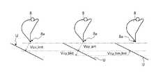
刃先8aが目標掘削地形より上方に位置しているときには、刃先8aが目標掘削地形に近づくほど、ブーム6の制限垂直速度成分Vcy_bm_lmtの絶対値が小さくなるとともに、目標掘削地形の表面に平行な方向へのブーム6の制限速度の速度成分(制限水平速度成分)Vcx_bm_lmtの絶対値も小さくなる。したがって、刃先8aが目標掘削地形より上方に位置しているときには、刃先8aが目標掘削地形に近づくほど、ブーム6の目標掘削地形の表面に垂直な方向への速度と、ブーム6の目標掘削地形の表面に平行な方向への速度とがともに減速される。油圧ショベル100のオペレータによって左操作レバー25L及び右操作レバー25Rが同時に操作されることにより、ブーム6とアーム7とバケット8とが同時に動作する。このとき、ブーム6とアーム7とバケット8との各目標速度Vc_bm、Vc_am、Vc_bktが入力されたとして、前述した制御を説明すると次の通りである。  When thecutting edge 8a is positioned above the target excavation landform, the absolute value of the limited vertical velocity component Vcy_bm_lmt of the boom 6 decreases as thecutting edge 8a approaches the target excavation landform, and the direction parallel to the surface of the target excavation landform The absolute value of the speed component of the speed limit of the boom 6 (restricted horizontal speed component) Vcx_bm_lmt is also reduced. Therefore, when thecutting edge 8a is positioned above the target excavation landform, the speed of the boom 6 in the direction perpendicular to the surface of the target excavation landform and the target excavation landform of the boom 6 are increased as thecutting edge 8a approaches the target excavation landform. The speed in the direction parallel to the surface of the surface is reduced. By operating theleft operation lever 25L and theright operation lever 25R simultaneously by the operator of the excavator 100, the boom 6, thearm 7, and thebucket 8 operate simultaneously. At this time, assuming that the target speeds Vc_bm, Vc_am, and Vc_bkt of the boom 6, thearm 7 and thebucket 8 are input, the above-described control will be described as follows.

図34は、目標掘削地形とバケット8の刃先8aとの間の距離dが所定値dth1より小さく、バケット8の刃先8aが位置Pn1から位置Pn2に移動する場合のブーム6の制限速度の変化の一例を示している。位置Pn2での刃先8aと目標掘削地形との間の距離は、位置Pn1での刃先8aと目標掘削地形との間の距離よりも小さい。このため、位置Pn2でのブーム6の制限垂直速度成分Vcy_bm_lmt2は、位置Pn1でのブーム6の制限垂直速度成分Vcy_bm_lmt1よりも小さい。したがって、位置Pn2でのブーム制限速度Vc_bm_lmt2は、位置Pn1でのブーム制限速度Vc_bm_lmt1よりも小さくなる。また、位置Pn2でのブーム6の制限水平速度成分Vcx_bm_lmt2は、位置Pn1でのブーム6の制限水平速度成分Vcx_bm_lmt1よりも小さくなる。ただし、このとき、アーム目標速度Vc_am及びバケット目標速度Vc_bktに対しては、制限は行われない。このため、アーム目標速度の垂直速度成分Vcy_am及び水平速度成分Vcx_amと、バケット目標速度の垂直速度成分Vcy_bkt及び水平速度成分Vcx_bktに対しては、制限は行われない。  FIG. 34 shows the change in the speed limit of the boom 6 when the distance d between the target excavation landform and thecutting edge 8a of thebucket 8 is smaller than a predetermined value dth1 and thecutting edge 8a of thebucket 8 moves from the position Pn1 to the position Pn2. An example is shown. The distance between theblade edge 8a and the target excavation landform at the position Pn2 is smaller than the distance between theblade edge 8a and the target excavation landform at the position Pn1. Therefore, the limited vertical speed component Vcy_bm_lmt2 of the boom 6 at the position Pn2 is smaller than the limited vertical speed component Vcy_bm_lmt1 of the boom 6 at the position Pn1. Therefore, the boom limit speed Vc_bm_lmt2 at the position Pn2 is smaller than the boom limit speed Vc_bm_lmt1 at the position Pn1. Further, the limited horizontal speed component Vcx_bm_lmt2 of the boom 6 at the position Pn2 is smaller than the limited horizontal speed component Vcx_bm_lmt1 of the boom 6 at the position Pn1. However, at this time, the arm target speed Vc_am and the bucket target speed Vc_bkt are not limited. For this reason, no limitation is imposed on the vertical velocity component Vcy_am and the horizontal velocity component Vcx_am of the arm target velocity, and the vertical velocity component Vcy_bkt and the horizontal velocity component Vcx_bkt of the bucket target velocity.

前述したように、アーム7に対して制限を行わないことにより、オペレータの掘削意思に対応するアーム操作量の変化は、バケット8の刃先8aの速度変化として反映される。このため、本実施形態は、目標掘削地形の侵食の拡大を抑制しながらオペレータの掘削時の操作における違和感を抑えることができる。  As described above, by not limiting thearm 7, a change in the arm operation amount corresponding to the operator's intention to excavate is reflected as a change in the speed of thecutting edge 8 a of thebucket 8. For this reason, this embodiment can suppress the uncomfortable feeling in the operation at the time of excavation of an operator, suppressing the expansion of erosion of the target excavation landform.

このように、本実施形態においては、作業機コントローラ26は、掘削対象の目標形状である設計地形を示す目標掘削地形とバケット8の刃先8aの位置を示す刃先位置データとに基づいて、目標掘削地形とバケット8の刃先8aとの距離dに応じてバケット8が目標掘削地形に近づく相対速度が小さくなるように、ブーム6の速度を制限する。作業機コントローラ26は、掘削対象の目標形状である設計地形を示す目標掘削地形とバケット8の刃先8aの位置を示す刃先位置データとに基づいて、目標掘削地形とバケット8の刃先8aとの距離dに応じて制限速度を決定し、作業機2が目標掘削地形に接近する方向の速度が制限速度以下になるように、作業機2を制御する。これにより、刃先8aに対する掘削制限制御が実行され、目標掘削地形に対する刃先8aの位置が自動調整される。  As described above, in this embodiment, thework machine controller 26 performs the target excavation based on the target excavation landform indicating the design landform that is the target shape of the excavation target and the blade edge position data indicating the position of theblade edge 8a of thebucket 8. The speed of the boom 6 is limited so that the relative speed at which thebucket 8 approaches the target excavation landform becomes small according to the distance d between the landform and theblade edge 8a of thebucket 8. Thework machine controller 26 determines the distance between the target excavation landform and theblade edge 8a of thebucket 8 based on the target excavation landform indicating the design landform that is the target shape to be excavated and the blade edge position data indicating the position of theblade edge 8a of thebucket 8. The speed limit is determined according to d, and the work implement 2 is controlled so that the speed in the direction in which the work implement 2 approaches the target excavation landform is equal to or less than the speed limit. Thereby, excavation restriction control for thecutting edge 8a is executed, and the position of thecutting edge 8a with respect to the target excavation landform is automatically adjusted.

制限掘削制御(介入制御)においては、目標掘削地形に対する刃先8aの侵入が抑制されるように、ブームシリンダ10に接続された制御弁27に制御信号が出力され、ブーム6の位置が制御される。介入制御は、相対速度Waが制限速度Vよりも大きいときに実行される。介入制御は、相対速度Waが制限速度Vよりも小さいときに実行されない。相対速度Waが制限速度Vよりも小さいことは、バケット8と目標掘削地形とが離れるように目標掘削地形に対してバケット8が移動することを含む。  In the limited excavation control (intervention control), a control signal is output to thecontrol valve 27 connected to theboom cylinder 10 so that the intrusion of theblade edge 8a into the target excavation landform is suppressed, and the position of the boom 6 is controlled. . The intervention control is executed when the relative speed Wa is larger than the speed limit V. The intervention control is not executed when the relative speed Wa is smaller than the speed limit V. That the relative speed Wa is smaller than the speed limit V includes the movement of thebucket 8 with respect to the target excavation landform so that thebucket 8 and the target excavation landform are separated.

なお、本実施形態において、2次元バケットデータSが目標掘削地形とバケット8との相対位置を導出するために用いられ、ローカル座標系から極座標系に座標変換された2次元バケットデータSが作業機2の制御に使用されてもよい。例えば、図35に示すように、アームトップ(バケット軸J3)が極座標系の原点となり、作業機動作平面MPにおけるバケット8の複数の輪郭点A、B、C、D、Eが、原点からの距離と、基準線に対する角度θA、θB、θC、θD、θEで表されてもよい。なお、基準線は、バケット軸J3とバケット8の先端部8aとを結ぶ線でもよい。極座標系を用いることにより、バケット8がチルトしたときの目標掘削地形とバケット8の先端部8aと作業機動作平面MPにおけるバケット8の断面の輪郭とが正しく演算され、目標掘削地形とバケット8の先端部8aとの距離を正確に算出することが可能となり、掘削制御の精度を確保できる。  In the present embodiment, the two-dimensional bucket data S is used for deriving the relative position between the target excavation landform and thebucket 8, and the two-dimensional bucket data S coordinate-converted from the local coordinate system to the polar coordinate system is used as the work implement. It may be used for the second control. For example, as shown in FIG. 35, the arm top (bucket axis J3) is the origin of the polar coordinate system, and a plurality of contour points A, B, C, D, E of thebucket 8 on the work machine operation plane MP are from the origin. The distance and the angles θA, θB, θC, θD, and θE with respect to the reference line may be used. The reference line may be a line connecting the bucket shaft J3 and thetip 8a of thebucket 8. By using the polar coordinate system, the target excavation landform when thebucket 8 is tilted, thetip 8a of thebucket 8 and the profile of the cross section of thebucket 8 on the work machine operation plane MP are correctly calculated. It is possible to accurately calculate the distance from thedistal end portion 8a, and to ensure the accuracy of excavation control.

[表示部]
図36は、表示部29の一例を示す図である。本実施形態においいて、表示部29は、目標掘削地形データU及びバケット位置データを含む2次元バケットデータSを表示する(ステップSP6)。表示部29は、作業機動作平面MPにおける目標掘削地形とバケット8との距離を示す距離データ、及び作業機動作平面MPにおけるバケット8の外形を示す外形データの少なくとも一方を表示する。
[Display section]
FIG. 36 is a diagram illustrating an example of thedisplay unit 29. In the present embodiment, thedisplay unit 29 displays the two-dimensional bucket data S including the target excavation landform data U and bucket position data (step SP6). Thedisplay unit 29 displays at least one of distance data indicating the distance between the target excavation landform on the work machine operation plane MP and thebucket 8 and outline data indicating the outline of thebucket 8 on the work machine operation plane MP.

表示部29の画面は、目標掘削地形とバケット8とを示す正面図282と、目標掘削地形とバケット8とを示す側面図281とを含む。正面図282は、バケット8を示すアイコン101と、立体設計地形(目標施工情報)の断面を示す線102とを含む。また、正面図282は、目標掘削地形とバケット8との距離(Z軸方向における距離)を示す距離データ291Aと、目標掘削地形と刃先8aとがなす角度を示す角度データ292Aとを含む。  The screen of thedisplay unit 29 includes afront view 282 showing the target excavation landform and thebucket 8, and aside view 281 showing the target excavation landform and thebucket 8. Thefront view 282 includes anicon 101 indicating thebucket 8 and aline 102 indicating a cross section of the three-dimensional design landform (target construction information). Thefront view 282 includesdistance data 291A indicating the distance between the target excavation landform and the bucket 8 (distance in the Z-axis direction) andangle data 292A indicating the angle formed by the target excavation landform and theblade edge 8a.

側面図281は、バケット8を示すアイコン103と、作業機動作平面MPにおける目標掘削地形の表面を示す線104とを含む。アイコン103は、作業機動作平面MPにおけるバケット8の外形を示す。また、側面図281は、目標掘削地形とバケット8との距離(目標掘削地形とバケット8との最短距離)を示す距離データ292Aと、目標掘削地形とバケット8の底面とがなす角度を示す角度データ292Bとを含む。  Side view 281 includesicon 103 indicatingbucket 8 andline 104 indicating the surface of the target excavation landform on work implement operation plane MP. Theicon 103 indicates the outer shape of thebucket 8 on the work machine operation plane MP. Further, theside view 281 shows the angle between thedistance data 292A indicating the distance between the target excavation landform and the bucket 8 (the shortest distance between the target excavation landform and the bucket 8) and the angle formed between the target excavation landform and the bottom surface of thebucket 8.Data 292B.

[効果]
以上説明したように、本実施形態によれば、チルト式バケットにおいて、制限掘削制御の制御対象となる作業機動作平面MPに沿ったバケット8の外形と目標掘削地形とを特定するようにしたので、バケット8のチルトにより、目標掘削地形とバケット8との距離が変化しても、バケット8が目標掘削地形に侵入しないように、精度良く制限掘削制御を行うことができる。
[effect]
As described above, according to the present embodiment, in the tilt type bucket, the outer shape of thebucket 8 and the target excavation landform along the work machine operation plane MP to be controlled by the limited excavation control are specified. Even if the distance between the target excavation landform and thebucket 8 changes due to the tilt of thebucket 8, the limited excavation control can be performed with high accuracy so that thebucket 8 does not enter the target excavation landform.

本実施形態においては、作業機2の寸法データと、バケット8の外形データと、作業機角度データと、チルト角度データとに基づいて、作業機動作平面MPにおけるバケット8の外形を示す2次元バケットデータを求めるようにしたので、バケット8のチルト角度が変動しても、作業機動作平面MPにおけるバケット8の刃先8aの位置を把握することができる。そのため、目標掘削地形と刃先8aとの相対位置を正確に把握して、掘削精度の低下を抑制しつつ、所期の施工を実行することができる。  In the present embodiment, a two-dimensional bucket indicating the outer shape of thebucket 8 in the work machine operation plane MP based on the dimension data of thework machine 2, the outer shape data of thebucket 8, the work machine angle data, and the tilt angle data. Since the data is obtained, the position of theblade edge 8a of thebucket 8 on the work machine operation plane MP can be grasped even if the tilt angle of thebucket 8 fluctuates. Therefore, it is possible to accurately grasp the relative position between the target excavation landform and thecutting edge 8a, and execute the intended construction while suppressing a decrease in excavation accuracy.

本実施形態においては、バケット8の外形データは、バケット8の幅方向に関して一端部におけるバケット8の第1輪郭データと、他端部におけるバケット8の第2輪郭データとを含み、第1輪郭データと第2輪郭データとバケット軸と平行な方向に関する作業機動作平面MPの位置とに基づいて、2次元バケットデータを求める。これにより、2次元バケットデータを精確かつ迅速に求めることができる。  In the present embodiment, the outer shape data of thebucket 8 includes the first contour data of thebucket 8 at one end and the second contour data of thebucket 8 at the other end with respect to the width direction of thebucket 8, and the first contour data. 2D bucket data is obtained based on the second contour data and the position of the work machine operation plane MP in the direction parallel to the bucket axis. As a result, the two-dimensional bucket data can be obtained accurately and quickly.

本実施形態においては、2次元バケットデータ、車両本体1の現在位置を示す車両本体位置データP、及び車両本体1の姿勢を示す車両本体姿勢データQに基づいて、目標掘削地形とバケット8との相対位置を求める。これにより、目標掘削地形とバケット8との相対位置を精確に求めることができる。  In the present embodiment, based on the two-dimensional bucket data, the vehicle body position data P indicating the current position of the vehicle body 1, and the vehicle body attitude data Q indicating the attitude of the vehicle body 1, the target excavation landform and thebucket 8 are Find the relative position. Thereby, the relative position between the target excavation landform and thebucket 8 can be accurately obtained.

本実施形態においては、2次元バケットデータに基づいて、作業機制御部26Aにより作業機2が制御される。これにより、作業機制御部26Aは、2次元バケットデータSと、作業機動作平面MPに沿った目標掘削地形とに基づいて、目標掘削地形とバケット8との距離dを導出して、作業機2の制限掘削制御を行うことができる。  In the present embodiment, the work implement 2 is controlled by the work implementcontrol unit 26A based on the two-dimensional bucket data. As a result, the work implementcontrol unit 26A derives the distance d between the target excavation landform and thebucket 8 based on the two-dimensional bucket data S and the target excavation landform along the work implement operation plane MP. 2 limited excavation control can be performed.

本実施形態においては、作業機制御部26Aは、目標掘削地形データUとバケット位置データとに基づいて、目標掘削地形とバケット8との距離に応じて制限速度を決定し、作業機2が目標掘削地形に接近する方向の速度が前記制限速度以下になるように作業機2を制御する。これにより、目標掘削地形にバケット8が侵入することが抑制され、掘削精度の低下が抑制される。  In the present embodiment, the workmachine control unit 26A determines the speed limit according to the distance between the target excavation landform and thebucket 8 based on the target excavation landform data U and the bucket position data, and thework machine 2 The work implement 2 is controlled so that the speed in the direction approaching the excavation landform is equal to or less than the speed limit. Thereby, thebucket 8 is prevented from entering the target excavation landform, and a decrease in excavation accuracy is suppressed.

本実施形態においては、目標掘削地形データ及びバケット位置データが表示部26に表示される。これにより、作業機動作平面MPを基準として制御対象が特定され、制限掘削制御が精度良く行われる。  In the present embodiment, target excavation landform data and bucket position data are displayed on thedisplay unit 26. Thereby, a control object is specified on the basis of the work machine operation plane MP, and the limited excavation control is performed with high accuracy.

なお、本実施形態においては、グローバル座標系における油圧ショベルCMの車両本体位置データP及び車両本体姿勢データQを取得し、ローカル座標系で求めたバケット8の位置(2次元バケットデータS)と、車両本体位置データP及び車両本体姿勢データQを用いて、グローバル座標系における目標掘削地形とバケット8との相対位置を取得することとした。目標掘削地形データをローカル座標系で規定して、ローカル座標系における目標掘削地形とバケット8との装置位置を取得してもよい。以下の実施形態においても同様である。  In the present embodiment, the vehicle body position data P and vehicle body attitude data Q of the hydraulic excavator CM in the global coordinate system are acquired, and the position of the bucket 8 (two-dimensional bucket data S) obtained in the local coordinate system; Using the vehicle body position data P and the vehicle body attitude data Q, the relative position between the target excavation landform and thebucket 8 in the global coordinate system is acquired. The target excavation landform data may be defined in the local coordinate system, and the device position between the target excavation landform and thebucket 8 in the local coordinate system may be acquired. The same applies to the following embodiments.

なお、本実施形態においては、2次元バケットデータSを用いて制限掘削制御(介入制御)を行うこととした。制限掘削制御は行われなくてもよい。例えば、オペレータが表示部29を目視し、作業機動作平面MPにおける目標掘削地形に沿ってバケット8が移動するように、操作装置25の操作が行われてもよい。以下の実施形態においても同様である。  In the present embodiment, the limited excavation control (intervention control) is performed using the two-dimensional bucket data S. The limited excavation control may not be performed. For example, theoperation device 25 may be operated such that the operator visually observes thedisplay unit 29 and thebucket 8 moves along the target excavation landform on the work machine operation plane MP. The same applies to the following embodiments.

[作業機動作平面のY座標の指定方法(第2実施形態)]
上述の実施形態においては、作業機動作平面MPのY座標がオペレータに指定される等の例について説明した。以下、作業機動作平面MPのY座標の指定方法の別の例について説明する。
[Method for Specifying Y Coordinate of Work Machine Operation Plane (Second Embodiment)]
In the above-described embodiment, the example in which the Y coordinate of the work machine operation plane MP is designated by the operator has been described. Hereinafter, another example of the method for specifying the Y coordinate of the work machine operation plane MP will be described.

上述の実施形態と同様、取得部28Cは、目標掘削地形を含み、掘削対象の3次元の目標形状である立体設計地形を示す目標施工情報Tを取得する。  Similar to the above-described embodiment, theacquisition unit 28C acquires the target construction information T that includes the target excavation landform and indicates the three-dimensional design landform that is a three-dimensional target shape to be excavated.

本実施形態において、演算部28Aは、作業機角度データ、チルト角度データ、車両本体位置データP、車両本体姿勢データQ、及びバケット8の外形データに基づいて、バケット8の先端部8a及びバケット8の外面に定められた複数の計測点Penのうち目標施工情報の表面に最も近い最接近点を求める。作業機動作平面MPが最接近点を通るように、作業機動作平面MPのY座標が指定される。  In the present embodiment, thearithmetic unit 28A is configured to use the work implement angle data, the tilt angle data, the vehicle main body position data P, the vehicle main body posture data Q, and the outer shape data of thebucket 8, and thetip 8a and thebucket 8 of thebucket 8. The closest point closest to the surface of the target construction information is obtained from a plurality of measurement points Pen determined on the outer surface of the target. The Y coordinate of the work implement operation plane MP is designated so that the work implement operation plane MP passes through the closest point.

表示コントローラ28は、バケットデータを取得する。バケットデータは、バケット8の外形データ及び作業機2の寸法データを含む。上述の実施形態と同様、バケット8の外形データ及び作業機2の寸法データは既知のデータである。バケット8の外形データは、バケット8の尻部の外形を含む。尻部とは、外側に膨らむように突出したバケット8の外面の一部の領域をいう。  Thedisplay controller 28 acquires bucket data. The bucket data includes outer shape data of thebucket 8 and dimension data of thework machine 2. Similar to the above-described embodiment, the outer shape data of thebucket 8 and the dimension data of thework machine 2 are known data. The outer shape data of thebucket 8 includes the outer shape of the bottom portion of thebucket 8. The bottom portion refers to a partial region of the outer surface of thebucket 8 that protrudes so as to bulge outward.

図37に示すように、計測点Pen(n=1、2、3、4、5)が、バケット8の尻部において異なる位置に複数定められる。計測点Penは、バケット8の幅方向と交差する方向に複数定められる。バケットデータは、バケット軸J3に対する放射方向に関するバケット軸J3と計測点Penとの距離En(n=1、2、3、4、5)を含む。バケットデータは、基準線と、バケット軸J3と計測点Penとを結ぶ線とがなす角度ψn(n=1、2、3、4、5)を含む。図29に示す例では、基準線は、バケット軸J3とバケット8の先端部8aとを結ぶ線である。  As shown in FIG. 37, a plurality of measurement points Pen (n = 1, 2, 3, 4, 5) are determined at different positions in the bottom of thebucket 8. A plurality of measurement points Pen are determined in a direction intersecting the width direction of thebucket 8. The bucket data includes a distance En (n = 1, 2, 3, 4, 5) between the bucket axis J3 and the measurement point Pen in the radial direction with respect to the bucket axis J3. The bucket data includes an angle ψn (n = 1, 2, 3, 4, 5) formed by a reference line and a line connecting the bucket axis J3 and the measurement point Pen. In the example shown in FIG. 29, the reference line is a line connecting the bucket shaft J3 and thetip 8a of thebucket 8.

表示コントローラ28は、作業機2の駆動において、バケット8の複数の計測点Penの現在位置を示す計測点位置データを取得する。また、表示コントローラ28は、バケット8の先端部8aの現在位置を示す先端部位置データを取得する。表示コントローラ28は、角度検出装置22によって検出される作業機角度データと、チルト角度センサ70によって検出されるチルト角度データと、既知データであるバケットデータとに基づいて、ローカル座標系における計測点Penの現在位置を示す計測点位置データ、及び先端部8aの現在位置を示す先端部位置データを取得することができる。  Thedisplay controller 28 acquires measurement point position data indicating the current positions of the plurality of measurement points Pen of thebucket 8 when thework machine 2 is driven. Further, thedisplay controller 28 acquires tip position data indicating the current position of thetip 8 a of thebucket 8. Thedisplay controller 28 measures the measurement point Pen in the local coordinate system based on the work machine angle data detected by theangle detection device 22, the tilt angle data detected by thetilt angle sensor 70, and the bucket data that is known data. Measurement point position data indicating the current position of the tip, and tip position data indicating the current position of thetip 8a can be acquired.

表示コントローラ28は、バケット8の計測点Penの現在位置と、取得した3次元設計地形データTとに基づいて、目標施工情報と、バケット8の計測点Penを通るXZ平面との交線(図18の交線E参照)で表される目標掘削地形を示す目標掘削地形データUを導出する。  Thedisplay controller 28 intersects the target construction information with the XZ plane passing through the measurement point Pen of thebucket 8 based on the current position of the measurement point Pen of thebucket 8 and the acquired three-dimensional design landform data T (see FIG. The target excavation landform data U indicating the target excavation landform represented by 18) is derived.

表示コントローラ28は、車両本体位置データP及び車両本体姿勢データQに基づいて、バケット8の先端部8a及び複数の計測点Penの現在位置を求めるとともに、先端部8a及び計測点Penのうち、目標施工情報の表面に最も近い部位(最接近点)を求める。  Thedisplay controller 28 obtains the current position of thetip 8a and the plurality of measurement points Pen of thebucket 8 based on the vehicle body position data P and the vehicle body posture data Q, and among thetip 8a and the measurement points Pen, Find the part closest to the surface of the construction information (the closest point).

計測点は、バケット8の幅方向と交差する方向のみならず、バケット8の幅方向にも複数定められる。図38は、バケット8の先端部8aと目標施工情報の表面との最短距離を説明するための図である。図38は、バケット8を上方から見た図に相当する。  A plurality of measurement points are determined not only in the direction intersecting the width direction of thebucket 8 but also in the width direction of thebucket 8. FIG. 38 is a diagram for explaining the shortest distance between thetip 8a of thebucket 8 and the surface of the target construction information. FIG. 38 corresponds to a view of thebucket 8 as seen from above.

図38に示すように、表示コントローラ28は、バケット8の先端部8aを通り、バケット8の幅方向の寸法と一致する仮想線分LSaを算出する。表示コントローラ28は、仮想線分LSaに複数の計測点Ci(i=1、2、3、4、5)を定める。計測点Ciは、先端部8aにおけるバケット8の幅方向に関する複数の位置を示す。表示コントローラ28は、車両本体位置データP及び車両本体姿勢データQに基づいて、計測点Ciの現在位置を求める。  As shown in FIG. 38, thedisplay controller 28 calculates a virtual line segment LSa that passes through thetip 8 a of thebucket 8 and matches the size in the width direction of thebucket 8. Thedisplay controller 28 determines a plurality of measurement points Ci (i = 1, 2, 3, 4, 5) on the virtual line segment LSa. The measurement points Ci indicate a plurality of positions in the width direction of thebucket 8 at thetip 8a. Thedisplay controller 28 obtains the current position of the measurement point Ci based on the vehicle body position data P and the vehicle body attitude data Q.

図39は、バケット8の尻部と目標施工情報の表面との最短距離を説明するための図である。図39は、バケット8を上方から見た図に相当する。  FIG. 39 is a diagram for explaining the shortest distance between the bottom of thebucket 8 and the surface of the target construction information. FIG. 39 corresponds to a view of thebucket 8 as viewed from above.

図39に示すように、表示コントローラ28は、バケット8の計測点Penを通り、バケット8の幅方向の寸法と一致する仮想線分LSenを算出する。表示コントローラ28は、仮想線分LSenに複数の計測点Ceni(i=1、2、3、4、5)を定める。計測点Ceniは、尻部におけるバケット8の幅方向に関する複数の位置を示す。表示コントローラ28は、車両本体位置データP及び車両本体姿勢データQに基づいて、計測点Ceniの現在位置を求める。  As shown in FIG. 39, thedisplay controller 28 calculates a virtual line segment Lsen that passes through the measurement point Pen of thebucket 8 and matches the size of thebucket 8 in the width direction. Thedisplay controller 28 defines a plurality of measurement points Ceni (i = 1, 2, 3, 4, 5) in the virtual line segment Lsen. The measurement points Ceni indicate a plurality of positions in the width direction of thebucket 8 at the bottom. Thedisplay controller 28 obtains the current position of the measurement point Ceni based on the vehicle body position data P and the vehicle body attitude data Q.

このように、複数の計測点は、バケット8の前後方向に関して複数設けられるとともに、バケット8の左右方向(幅方向)に関して複数設けられる。すなわち、複数の計測点は、バケット8の外面においてマトリクス状に設けられる。  As described above, a plurality of measurement points are provided in the front-rear direction of thebucket 8 and are provided in the left-right direction (width direction) of thebucket 8. That is, the plurality of measurement points are provided in a matrix on the outer surface of thebucket 8.

図40は、バケット8を側面からみた目標施工情報とバケット8との最短距離を説明するための図である。第i計測点Ci、Ceniを通るXZ平面と、目標施工情報の表面との交線を交線Miとした場合、表示コントローラ28は、交線Miに含まれる各交線MAi、MBi、MCiと第i計測点Ci、Ceniとの間の距離を算出する。ここでは、交線Miに含まれる各交線MAi、MBi、MCiについて、第i計測点Ci、Ceniを通る垂線を算出し、交線MAi、MBi、MCiと第i計測点Ci、Ceniとの間の距離が算出される。例えば、図38、図39、及び図40に示すように、第i計測点Ciが目標領域A1、A2、A3のうち目標領域A1内に位置している、第i計測点Ciを通る交線MAiの垂線が算出され、第i計測点Ci、Ceniと交線MAiとの間の距離DAi、Deniが算出される。また、図38、図39、及び図40に示すように、第i計測点Ci、Ceniが目標領域A1、A2、A3のうち目標領域A3内に位置している、第i計測点Ci、Ceniを通る交線MCiの垂線が算出され、第i計測点Ci、Ceniと交線MCiとの間の設計面距離DAic、Denicが算出される。このようにして、表示コントローラ28は、図38、図39、及び図40に示す算出可能な距離から、最小の距離となる最短距離を求める。  FIG. 40 is a diagram for explaining the shortest distance between the target construction information and thebucket 8 when thebucket 8 is viewed from the side. When the intersection line between the XZ plane passing through the i-th measurement point Ci and Ceni and the surface of the target construction information is the intersection line Mi, thedisplay controller 28 includes the intersection lines MAi, MBi, and MCi included in the intersection line Mi. A distance between the i-th measurement point Ci and Ceni is calculated. Here, for each intersection line MAi, MBi, MCi included in the intersection line Mi, a perpendicular line passing through the i-th measurement point Ci, Ceni is calculated, and the intersection line MAi, MBi, MCi and the i-th measurement point Ci, Ceni The distance between is calculated. For example, as shown in FIGS. 38, 39, and 40, the i-th measurement point Ci is located in the target area A1 among the target areas A1, A2, and A3, and the intersection line passing through the i-th measurement point Ci. A perpendicular line of MAi is calculated, and distances DAi and Deni between the i-th measurement points Ci and Ceni and the intersection line MAi are calculated. Also, as shown in FIGS. 38, 39, and 40, the i-th measurement point Ci, Ceni, where the i-th measurement point Ci, Ceni is located in the target area A3 among the target areas A1, A2, A3. The perpendicular of the intersecting line MCi passing through is calculated, and the design surface distances DAic and Denic between the i-th measurement points Ci and Ceni and the intersecting line MCi are calculated. In this way, thedisplay controller 28 determines the shortest distance that is the minimum distance from the calculable distances shown in FIGS. 38, 39, and 40.

表示コントローラ28は、複数の交線MAi及び交線MCiの法線方向に同一の計測点Pe1、刃先8aの位置がある場合、計測点Pe1、刃先8aに対して複数の距離De1i、DAiを求める。  Thedisplay controller 28 obtains a plurality of distances De1i and DAi with respect to the measurement point Pe1 and theblade edge 8a when the positions of the same measurement point Pe1 and theblade edge 8a are in the normal direction of the plurality of intersection lines MAi and the intersection line MCi. .

このように、車両本体位置データP及び車両本体姿勢データQに基づいて、バケット8の外面においてマトリクス状に定められた複数の計測点(バケット8の先端部8aの計測点を含む)のうち、目標施工情報の表面に最も近い最接近計測点が求められる。作業機動作平面MPは、その最接近計測点を通るように指定される。  Thus, based on the vehicle body position data P and the vehicle body posture data Q, among the plurality of measurement points (including the measurement points of thetip 8a of the bucket 8) defined in a matrix on the outer surface of thebucket 8, The closest measurement point closest to the surface of the target construction information is obtained. The work machine operation plane MP is specified so as to pass through the closest measurement point.

以上、本発明の一実施形態について説明したが、本発明は上記実施形態に限定されるものではなく、発明の要旨を逸脱しない範囲で種々の変更が可能である。  As mentioned above, although one Embodiment of this invention was described, this invention is not limited to the said embodiment, A various change is possible in the range which does not deviate from the summary of invention.

上記の実施形態では、建設機械の一例として油圧ショベルを挙げているが油圧ショベルに限らず、他の種類の建設機械に本発明が適用されてもよい。  In the above embodiment, a hydraulic excavator is cited as an example of a construction machine. However, the present invention is not limited to the hydraulic excavator and may be applied to other types of construction machines.

グローバル座標系における油圧ショベルCMの位置の取得は、GNSSに限らず、他の測位手段によって行われてもよい。従って、バケット8と目標掘削地形との距離dの取得は、GNSSに限らず、他の測位手段によって行われてもよい。  Acquisition of the position of the hydraulic excavator CM in the global coordinate system is not limited to GNSS, and may be performed by other positioning means. Therefore, acquisition of the distance d between thebucket 8 and the target excavation landform is not limited to GNSS, and may be performed by other positioning means.

ブーム操作量とアーム操作量とバケット操作量とは、パイロット油圧方式以外に、操作レバー(25R、25L)の操作を示す電気的な信号を出力する方式として、操作レバーの操作信号を作業機コントローラ26に入力してもよい。各コントローラにおいて行われる各処理はその他のコントローラで行うこととしてもよい。  The boom operation amount, the arm operation amount, and the bucket operation amount are not limited to the pilot hydraulic method, and the operation signal of the operation lever is used as a method for outputting an electric signal indicating the operation of the operation lever (25R, 25L). 26 may be input. Each process performed in each controller may be performed by another controller.

1 車両本体
2 作業機
3 旋回体
4 運転室
5 走行装置
5Cr 履帯
6 ブーム
7 アーム
8 バケット
9 エンジンルーム
10 ブームシリンダ
11 アームシリンダ
12 バケットシリンダ
13 ブームピン
14 アームピン
15 バケットピン
16 第1ストロークセンサ
17 第2ストロークセンサ
18 第3ストロークセンサ
19 手すり
20 位置検出装置
21 アンテナ
22 角度検出装置
23 位置センサ
24 傾斜センサ
25 操作装置
25F 操作ペダル
25L 第2操作レバー
25R 第1操作レバー
25P 第3操作レバー
26 作業機コントローラ
27 制御弁
28 表示コントローラ
29 表示部
30 チルトシリンダ
32 センサコントローラ
36 入力部
40A キャップ側油室
40B ロッド側油室
41 メイン油圧ポンプ
42 パイロット油圧ポンプ
43 メインバルブ
51 シャトル弁
70 チルト角度センサ
80 チルトピン
81 底板
82 背板
83 上板
84 側板
85 側板
86 開口部
87 ブラケット
88 ブラケット
90 接続部材
91 プレート部材
92 ブラケット
93 ブラケット
94 第1リンク部材
94P 第1リンクピン
95 第2リンク部材
95P 第2リンクピン
96 バケットシリンダトップピン
97 ブラケット
161 回転ローラ
162 回転中心軸
163 回転センサ部
164 ケース
200 制御システム
300 油圧システム
AX 旋回軸
CM 建設機械(油圧ショベル)
J1 ブーム軸
J2 アーム軸
J3 バケット軸
J4 チルト軸
L1 ブーム長さ
L2 アーム長さ
L3 バケット長さ
L4 チルト長さ
L5 バケットの幅の寸法
P 車両本体位置データ
Q 車両本体姿勢データ(旋回体方位データ)
S 2次元バケットデータ
T 目標施工情報
U 目標掘削地形データ
α ブームの回転角度
β アームの回転角度
γ バケットの回転角度
δ チルト角度
ε チルト軸角度
DESCRIPTION OF SYMBOLS 1 Vehiclemain body 2 Work implement 3Revolving body 4 Driver's cab 5 Traveling device 5Cr Crawler belt 6Boom 7Arm 8 Bucket 9Engine room 10Boom cylinder 11Arm cylinder 12Bucket cylinder 13Boom pin 14Arm pin 15Bucket pin 161st stroke sensor 172nd Stroke sensor 18Third stroke sensor 19Handrail 20Position detection device 21Antenna 22Angle detection device 23Position sensor 24Tilt sensor 25Operation device25F Operation pedal 25LSecond operation lever 25RFirst operation lever 25PThird operation lever 26 Work implementcontroller 27Control valve 28Display controller 29Display unit 30Tilt cylinder 32Sensor controller 36Input unit 40A Capside oil chamber 40B Rodside oil chamber 41 Mainhydraulic pump 42 Pilothydraulic pump 43Valve 51Shuttle valve 70Tilt angle sensor 80Tilt pin 81Bottom plate 82Back plate 83Top plate 84Side plate 85Side plate 86Opening 87Bracket 88Bracket 90Connection member 91Plate member 92Bracket 93 Bracket 94First link member 94P First linkpin 95Second link member 95PSecond link pin 96 Bucket cylindertop pin 97Bracket 161Rotating roller 162Rotation center shaft 163Rotation sensor unit 164Case 200Control system 300 Hydraulic system AX Rotating shaft CM Construction machine (hydraulic excavator)
J1 Boom axis J2 Arm axis J3 Bucket axis J4 Tilt axis L1 Boom length L2 Arm length L3 Bucket length L4 Tilt length L5 Bucket width dimension P Vehicle body position data Q Vehicle body posture data (swivel body orientation data)
S Two-dimensional bucket data T Target construction information U Target excavation landform data α Boom rotation angle β Arm rotation angle γ Bucket rotation angle δ Tilt angle ε Tilt axis angle

Claims (9)

Translated fromJapanese
ブーム軸を中心に車両本体に対して回転可能なブームと、前記ブーム軸と平行なアーム軸を中心に前記ブームに対して回転可能なアームと、前記アーム軸と平行なバケット軸及び前記バケット軸と直交するチルト軸のそれぞれを中心に前記アームに対して回転可能なバケットとを含む作業機を備える建設機械の制御システムであって、
前記ブームの寸法、前記アームの寸法、及び前記バケットの寸法を含む寸法データを取得する第1取得部と、
前記バケット外面の輪郭データ及び前記バケット幅データを含む前記バケットの外形データを取得する第2取得部と、
前記バケット軸と直交する作業機動作平面における掘削対象の2次元の目標形状である目標掘削地形を示す目標掘削地形データを取得する第3取得部と、
前記ブーム軸を中心とする前記ブームの回転角度を示すブーム角度データ、前記アーム軸を中心とする前記アームの回転角度を示すアーム角度データ、及び前記バケット軸を中心とする前記バケットの回転角度を示すバケット角度データを含む作業機角度データを取得する第4取得部と、
前記チルト軸を中心とする前記バケットの回転角度を示すチルト角度データを取得する第5取得部と、
前記寸法データ、前記外形データ、前記作業機角度データ、及びチルト角度データに基づいて、前記作業機動作平面における前記バケットの外形を示す2次元バケットデータを求める演算部と、
を備える建設機械の制御システム。
A boom that can rotate with respect to the vehicle main body about the boom axis, an arm that can rotate with respect to the boom about an arm axis that is parallel to the boom axis, a bucket axis that is parallel to the arm axis, and the bucket axis A construction machine control system comprising a work machine including a bucket that is rotatable with respect to the arm about each of tilt axes orthogonal to
A first acquisition unit for acquiring dimensional data including the dimensions of the boom, the dimensions of the arm, and the dimensions of the bucket;
A second acquisition unit for acquiring outer shape data of the bucket including contour dataof the outer surface of the bucketand width data of the bucket;
A third acquisition unit that acquires target excavation landform data indicating a target excavation landform that is a two-dimensional target shape of an excavation target in a work machine operation plane orthogonal to the bucket axis;
Boom angle data indicating a rotation angle of the boom around the boom axis, arm angle data indicating a rotation angle of the arm around the arm axis, and a rotation angle of the bucket around the bucket axis. A fourth acquisition unit for acquiring work machine angle data including bucket angle data to be shown;
A fifth acquisition unit that acquires tilt angle data indicating a rotation angle of the bucket around the tilt axis;
An operation unit for obtaining two-dimensional bucket data indicating the outer shape of the bucket in the work implement operation plane based on the dimension data, the outer shape data, the work implement angle data, and the tilt angle data;
A construction machine control system comprising:
前記バケットの外形データは、前記バケットの幅方向に関して一端部における前記バケットの外面の輪郭を含む第1輪郭データと、他端部における前記バケットの外面の輪郭を含む第2輪郭データとを含み、
前記演算部は、前記第1輪郭データと、前記作業機動作平面の位置と、バケット刃先の位置とに基づいて、前記2次元バケットデータを求める請求項1に記載の建設機械の制御システム。
The outer shape data of the bucket includes first contour data including a contour of the outer surface of the bucket at one end with respect to a width direction of the bucket, and second contour data including a contour of the outer surface of the bucket at the other end.
2. The construction machine control system according to claim 1, wherein the calculation unit obtains the two-dimensional bucket data based on the first contour data, the position of the work machine operation plane, and the position of a bucket blade edge.
前記演算部は、前記2次元バケットデータ、前記車両本体の現在位置を示す車両本体位置データ、及び前記車両本体の姿勢を示す車両本体姿勢データに基づいて、前記目標掘削地形と前記バケットとの相対位置を求める請求項1又は請求項2に記載の建設機械の制御システム。  The arithmetic unit is configured to determine a relative position between the target excavation landform and the bucket based on the two-dimensional bucket data, vehicle body position data indicating a current position of the vehicle body, and vehicle body attitude data indicating an attitude of the vehicle body. The construction machine control system according to claim 1 or 2, wherein the position is obtained. 前記第3取得部は、前記目標掘削地形を含み、掘削対象の3次元の目標形状である立体設計地形を示す目標施工情報を取得し、
前記演算部は、前記作業機角度データ、前記チルト角度データ、前記車両本体位置データ、前記車両本体姿勢データ、及び前記バケットの外形データに基づいて、前記バケットの先端部及び前記バケットの外面に定められた複数の計測点のうち前記立体設計地形の表面に最も近い最接近点を求め、
前記作業機動作平面は、前記最接近点を通る請求項3に記載の建設機械の制御システム。
The third acquisition unit includes the target excavation landform, and acquires target construction information indicating a three-dimensional design landform that is a three-dimensional target shape to be excavated,
The calculation unit is determined on the tip of the bucket and the outer surface of the bucket based on the work machine angle data, the tilt angle data, the vehicle body position data, the vehicle body posture data, and the bucket outer shape data. Find the closest point to the surface of the three-dimensional design terrain among the plurality of measurement points
The construction machine control system according to claim 3, wherein the work machine operation plane passes through the closest point.
前記2次元バケットデータに基づいて、前記作業機を制御する作業機制御部を備える請求項1から請求項4のいずれか一項に記載の建設機械の制御システム。  The construction machine control system according to any one of claims 1 to 4, further comprising a work machine control unit that controls the work machine based on the two-dimensional bucket data. 前記2次元バケットデータは、前記作業機動作平面における前記バケットの現在位置を示すバケット位置データを含み、
前記作業機制御部は、前記目標掘削地形データと前記バケット位置データとに基づいて、前記目標掘削地形と前記バケットとの距離に応じて制限速度を決定し、前記作業機が前記目標掘削地形に接近する方向の速度が前記制限速度以下になるように前記ブームの速度を制限する請求項5に記載の建設機械の制御システム。
The two-dimensional bucket data includes bucket position data indicating a current position of the bucket in the work machine operation plane,
The work implement control unit determines a speed limit according to a distance between the target excavation landform and the bucket based on the target excavation landform data and the bucket position data, and the work implement is set to the target excavation landform. The construction machine control system according to claim 5, wherein the speed of the boom is limited so that a speed in an approaching direction is equal to or less than the speed limit.
前記2次元バケットデータは、前記作業機動作平面における前記バケットの現在位置を示すバケット位置データを含み、
前記目標掘削地形データ及び前記バケット位置データを表示する表示部を備える請求項1から請求項6のいずれか一項に記載の建設機械の制御システム。
The two-dimensional bucket data includes bucket position data indicating a current position of the bucket in the work machine operation plane,
The construction machine control system according to any one of claims 1 to 6, further comprising a display unit that displays the target excavation landform data and the bucket position data.
下部走行体と、
前記下部走行体に支持される上部旋回体と、
ブームとアームとバケットとを含み、前記上部旋回体に支持される作業機と、
請求項1から請求項7のいずれか一項に記載の制御システムと、
を備える建設機械。
A lower traveling body,
An upper swing body supported by the lower traveling body;
A work machine including a boom, an arm, and a bucket, and supported by the upper swing body;
A control system according to any one of claims 1 to 7,
Construction machinery comprising.
ブーム軸を中心に車両本体に対して回転可能なブームと、前記ブーム軸と平行なアーム軸を中心に前記ブームに対して回転可能なアームと、前記アーム軸と平行なバケット軸及び前記バケット軸と直交するチルト軸のそれぞれを中心に前記アームに対して回転可能なバケットとを含む作業機を備える建設機械の制御方法であって、
前記ブームの寸法、前記アームの寸法、及び前記バケットの寸法を含む寸法データを取得することと、
前記バケット外面の輪郭データ及び前記バケット幅データを含む前記バケットの外形データを取得することと、
前記ブーム軸を中心とする前記ブームの回転角度を示すブーム角度データ、前記アーム軸を中心とする前記アームの回転角度を示すアーム角度データ、及び前記バケット軸を中心とする前記バケットの回転角度を示すバケット角度データを含む作業機角度データを取得することと、
前記チルト軸を中心とする前記バケットの回転角度を示すチルト角度データを取得することと、
前記バケット軸と直交する作業機動作平面における掘削対象の2次元の目標形状である目標掘削地形を示す目標掘削地形データを指定することと、
前記寸法データ、前記外形データ、前記作業機角度データ、及びチルト角度データに基づいて、前記作業機動作平面における前記バケットの外形を示す2次元バケットデータを求めることと、
前記2次元バケットデータに基づいて、前記作業機を制御することと、
を含む建設機械の制御方法。
A boom that can rotate with respect to the vehicle main body about the boom axis, an arm that can rotate with respect to the boom about an arm axis that is parallel to the boom axis, a bucket axis that is parallel to the arm axis, and the bucket axis A construction machine control method including a working machine including a bucket that is rotatable with respect to the arm about each of tilt axes orthogonal to each other,
Obtaining dimensional data including dimensions of the boom, dimensions of the arm, and dimensions of the bucket;
Obtaining outline data of the bucket including contour dataof the outer surface of the bucketand width data of the bucket;
Boom angle data indicating a rotation angle of the boom around the boom axis, arm angle data indicating a rotation angle of the arm around the arm axis, and a rotation angle of the bucket around the bucket axis. Obtaining work implement angle data including bucket angle data to indicate;
Obtaining tilt angle data indicating a rotation angle of the bucket around the tilt axis;
Designating target excavation landform data indicating a target excavation landform that is a two-dimensional target shape of an excavation target in a work machine operation plane orthogonal to the bucket axis;
Obtaining two-dimensional bucket data indicating the outer shape of the bucket in the work implement operation plane based on the dimension data, the outer shape data, the work implement angle data, and the tilt angle data;
Controlling the work implement based on the two-dimensional bucket data;
Control method of construction machinery including
JP2014528363A2014-06-022014-06-02 Construction machine control system, construction machine, and construction machine control methodActiveJP5848451B1 (en)

Applications Claiming Priority (1)

Application NumberPriority DateFiling DateTitle
PCT/JP2014/064648WO2015186180A1 (en)2014-06-022014-06-02Construction machine control system, construction machine, and construction machine control method

Publications (2)

Publication NumberPublication Date
JP5848451B1true JP5848451B1 (en)2016-01-27
JPWO2015186180A1 JPWO2015186180A1 (en)2017-04-20

Family

ID=54766282

Family Applications (1)

Application NumberTitlePriority DateFiling Date
JP2014528363AActiveJP5848451B1 (en)2014-06-022014-06-02 Construction machine control system, construction machine, and construction machine control method

Country Status (6)

CountryLink
US (1)US9856628B2 (en)
JP (1)JP5848451B1 (en)
KR (1)KR101746324B1 (en)
CN (1)CN105431597B (en)
DE (1)DE112014000077B4 (en)
WO (1)WO2015186180A1 (en)

Families Citing this family (52)

* Cited by examiner, † Cited by third party
Publication numberPriority datePublication dateAssigneeTitle
AU2012202213B2 (en)*2011-04-142014-11-27Joy Global Surface Mining IncSwing automation for rope shovel
US8573334B2 (en)*2011-12-162013-11-05Entro Industries, Inc.Rotation device for load transporting apparatus
EP4043643A1 (en)*2015-03-272022-08-17Sumitomo (S.H.I.) Construction Machinery Co., Ltd.Shovel
DE112015000068B4 (en)*2015-06-292020-09-24Komatsu Ltd. Construction machine control system and construction machine control method
JP6532797B2 (en)*2015-10-082019-06-19日立建機株式会社 Construction machinery
US9618348B1 (en)*2015-12-112017-04-11Caterpillar Inc.Spotting location system of a loading machine
JP6474718B2 (en)2015-12-252019-02-27日立建機株式会社 Hydraulic control equipment for construction machinery
US9988787B1 (en)*2016-03-102018-06-05Robo Industries, Inc.System for determining position of a vehicle
WO2016186218A1 (en)*2016-05-312016-11-24株式会社小松製作所Construction machinery control system, construction machinery, and construction machinery control method
KR101839467B1 (en)*2016-05-312018-03-16가부시키가이샤 고마쓰 세이사쿠쇼Construction machinery control system, construction machinery, and construction machinery control method
US10323381B2 (en)2016-06-242019-06-18Komatsu Ltd.Work vehicle and method of controlling work vehicle
JP6564739B2 (en)*2016-06-302019-08-21日立建機株式会社 Work machine
US10794046B2 (en)*2016-09-162020-10-06Hitachi Construction Machinery Co., Ltd.Work machine
US10526765B2 (en)2016-11-092020-01-07Komatsu Ltd.Work vehicle and control method
CN108368688B (en)*2016-11-092021-04-02株式会社小松制作所 Work vehicle and data correction method
CN108291387B (en)*2016-11-092020-11-10株式会社小松制作所Work machine and work machine control method
JP6856548B2 (en)2017-01-102021-04-07株式会社小松製作所 Work vehicle and control method
JP6781067B2 (en)*2017-02-212020-11-04株式会社小松製作所 Construction Machinery Control Systems, Construction Machinery, and Construction Machinery Control Methods
JP6872945B2 (en)*2017-03-272021-05-19日立建機株式会社 Construction machinery
DE112017000085T5 (en)*2017-07-142019-04-18Komatsu Ltd. WORK MACHINE AND CONTROL PROCESS FOR WORK MACHINE
JP6901336B2 (en)*2017-07-142021-07-14株式会社小松製作所 Construction machinery, calibration systems, and methods
US11987949B2 (en)2017-08-302024-05-21Topcon Positioning Systems, Inc.Method and apparatus for machine operator command attenuation
JP6807290B2 (en)*2017-09-142021-01-06日立建機株式会社 Work machine
US11149411B2 (en)*2018-03-122021-10-19Hitachi Construction Machinery Co., Ltd.Work machine
JP6854255B2 (en)*2018-03-152021-04-07日立建機株式会社 Construction machinery
JP6969475B2 (en)*2018-03-282021-11-24コベルコ建機株式会社 Construction machinery
CN108519613A (en)*2018-04-092018-09-11山东天星北斗信息科技有限公司 Auxiliary construction system and construction method for auger excavator
US10801180B2 (en)*2018-06-112020-10-13Deere & CompanyWork machine self protection system
CN111201350B (en)*2018-09-202022-02-25日立建机株式会社Working machine
KR102685684B1 (en)*2018-11-142024-07-15스미도모쥬기가이고교 가부시키가이샤 Shovel, shovel control device
JP7197392B2 (en)*2019-02-012022-12-27株式会社小松製作所 CONSTRUCTION MACHINE CONTROL SYSTEM, CONSTRUCTION MACHINE, AND CONSTRUCTION MACHINE CONTROL METHOD
JP7179644B2 (en)*2019-02-252022-11-29三菱重工エンジニアリング株式会社 Control device, moving body and control method
US11401689B2 (en)*2019-03-152022-08-02Built Robotics Inc.Sensor retrofit to autonomously actuate an excavation vehicle
JP7222775B2 (en)*2019-03-262023-02-15日立建機株式会社 working machine
WO2021010489A1 (en)*2019-07-172021-01-21住友建機株式会社Work machine and assistance device that assists work using work machine
CN114174597B (en)*2019-07-312024-01-16住友重机械工业株式会社 Excavator
US11408449B2 (en)2019-09-272022-08-09Topcon Positioning Systems, Inc.Dithering hydraulic valves to mitigate static friction
US11828040B2 (en)2019-09-272023-11-28Topcon Positioning Systems, Inc.Method and apparatus for mitigating machine operator command delay
KR20220068978A (en)*2019-09-302022-05-26스미도모쥬기가이고교 가부시키가이샤 shovel, shovel control device
JP7149917B2 (en)2019-09-302022-10-07日立建機株式会社 working machine
US11702819B2 (en)*2019-11-252023-07-18Deere & CompanyElectrohydraulic implement control system and method
JP7396875B2 (en)*2019-11-272023-12-12株式会社小松製作所 Work machine control system, work machine, and work machine control method
JP7402026B2 (en)*2019-11-272023-12-20株式会社小松製作所 Work machine control system, work machine, work machine control method
KR102125664B1 (en)*2020-01-132020-06-22이상룡Apparatus for detecting excavation level
CN111761574B (en)*2020-05-282022-08-02中联重科股份有限公司 Method and device for judging the safety of operations that can be performed by a boom, and construction machinery
DE102020118938B3 (en)*2020-07-172021-07-29OilQuick Deutschland KG Quick change system for changing attachments on a construction machine
CN112281940B (en)*2020-10-192022-09-09三一重机有限公司Excavator and control method thereof
CN112281974A (en)*2020-11-232021-01-29中国矿业大学Excavator bucket with gear driven swinging and hydraulic enhanced excavating force
JP7559667B2 (en)*2021-04-262024-10-02コベルコ建機株式会社 Target Trajectory Generation System
RU207548U1 (en)*2021-06-102021-11-01Федеральное государственное бюджетное образовательное учреждение высшего образования "Брянский государственный аграрный университет" EXCAVATOR BUCKET
JP2023050975A (en)*2021-09-302023-04-11株式会社小松製作所 Systems and methods for controlling work machines
CN115012907B (en)*2022-07-202024-10-29辽宁数智矿业科技有限公司Auxiliary drilling system and method for rotary drill

Citations (3)

* Cited by examiner, † Cited by third party
Publication numberPriority datePublication dateAssigneeTitle
WO2012127913A1 (en)*2011-03-242012-09-27株式会社小松製作所Excavation control system and construction machinery
WO2012127914A1 (en)*2011-03-242012-09-27株式会社小松製作所Excavation control system
JP2014074319A (en)*2012-10-052014-04-24Komatsu LtdDisplay system of excavator, excavator and computer program for display of excavator

Family Cites Families (19)

* Cited by examiner, † Cited by third party
Publication numberPriority datePublication dateAssigneeTitle
JPS59195936A (en)*1983-04-211984-11-07Komatsu Ltd How to monitor the working status of excavating machines
US5019761A (en)*1989-02-211991-05-28Kraft Brett WForce feedback control for backhoe
KR100353566B1 (en)*1997-02-132003-01-06히다치 겡키 가부시키 가이샤 A slope excavation control device of a hydraulic excavator, a target slope setting device, and a slope excavation forming method
CN1249307C (en)*2000-11-172006-04-05日立建机株式会社Display device and display controller of construction machinery
JPWO2003000997A1 (en)*2001-06-202004-10-14日立建機株式会社 Construction machine remote control system and remote setting system
KR100621976B1 (en)2002-04-242006-09-13볼보 컨스트럭션 이키프먼트 홀딩 스웨덴 에이비 Heavy construction equipment with positive control boom down function
EP1541772B1 (en)*2002-09-172015-08-05Hitachi Construction Machinery Co., Ltd.Excavation teaching apparatus for construction machine
JP4233932B2 (en)*2003-06-192009-03-04日立建機株式会社 Work support / management system for work machines
CN100545359C (en)*2003-09-022009-09-30株式会社小松制作所Construction target instructing device
GB0410415D0 (en)*2004-05-112004-06-16Bamford Excavators LtdOperator display system
JP4958567B2 (en)*2007-01-122012-06-20日立建機株式会社 Information collection device for construction machinery
US7810260B2 (en)*2007-12-212010-10-12Caterpillar Trimble Control Technologies LlcControl system for tool coupling
US9611620B2 (en)*2009-09-042017-04-04Philip PaullApparatus and method for enhanced grading control
JP5555190B2 (en)*2011-02-222014-07-23株式会社小松製作所 Hydraulic excavator display system and control method thereof
JP5059953B2 (en)*2011-02-222012-10-31株式会社小松製作所 Work range display device for hydraulic excavator and control method thereof
JP5237408B2 (en)*2011-03-242013-07-17株式会社小松製作所 Hydraulic excavator calibration system and calibration method
US20140064897A1 (en)*2012-08-292014-03-06Deere And CompanySingle stick operation of a work tool
US8965642B2 (en)*2012-10-052015-02-24Komatsu Ltd.Display system of excavating machine and excavating machine
JP6053714B2 (en)*2014-03-312016-12-27日立建機株式会社 Excavator

Patent Citations (3)

* Cited by examiner, † Cited by third party
Publication numberPriority datePublication dateAssigneeTitle
WO2012127913A1 (en)*2011-03-242012-09-27株式会社小松製作所Excavation control system and construction machinery
WO2012127914A1 (en)*2011-03-242012-09-27株式会社小松製作所Excavation control system
JP2014074319A (en)*2012-10-052014-04-24Komatsu LtdDisplay system of excavator, excavator and computer program for display of excavator

Also Published As

Publication numberPublication date
WO2015186180A1 (en)2015-12-10
CN105431597B (en)2017-12-29
KR101746324B1 (en)2017-06-12
JPWO2015186180A1 (en)2017-04-20
DE112014000077T5 (en)2016-02-18
DE112014000077B4 (en)2018-04-05
US20160251835A1 (en)2016-09-01
CN105431597A (en)2016-03-23
US9856628B2 (en)2018-01-02
KR20160021073A (en)2016-02-24

Similar Documents

PublicationPublication DateTitle
JP5848451B1 (en) Construction machine control system, construction machine, and construction machine control method
JP5856685B1 (en) Construction machine control system, construction machine, and construction machine control method
JP5990642B2 (en) Construction machine control system, construction machine, and construction machine control method
US9663917B2 (en)Work vehicle, bucket device, and method for obtaining tilt angle
JP5791827B2 (en) Work vehicle
JP5864775B2 (en) Work vehicle
KR101839467B1 (en)Construction machinery control system, construction machinery, and construction machinery control method
KR101907938B1 (en)Control device for construction machine and method of controlling construction machine
US9689145B1 (en)Work vehicle and method for obtaining tilt angle
JPWO2015137525A1 (en) Construction machine control system, construction machine, and construction machine control method
WO2015137524A1 (en)Construction machine control system, construction machine, and method for controlling construction machine
JPWO2015025985A1 (en) Work vehicle and control method of work vehicle
KR20180135939A (en) Control system of construction machine, construction machine, and control method of construction machine

Legal Events

DateCodeTitleDescription
TRDDDecision of grant or rejection written
A01Written decision to grant a patent or to grant a registration (utility model)

Free format text:JAPANESE INTERMEDIATE CODE: A01

Effective date:20151117

A61First payment of annual fees (during grant procedure)

Free format text:JAPANESE INTERMEDIATE CODE: A61

Effective date:20151126

R150Certificate of patent or registration of utility model

Ref document number:5848451

Country of ref document:JP

Free format text:JAPANESE INTERMEDIATE CODE: R150

R250Receipt of annual fees

Free format text:JAPANESE INTERMEDIATE CODE: R250


[8]ページ先頭

©2009-2025 Movatter.jp