JP5846395B2 - Transcatheter prosthetic heart valve delivery device using funnel recapture function and method - Google Patents
Transcatheter prosthetic heart valve delivery device using funnel recapture function and methodDownload PDFInfo
- Publication number
- JP5846395B2 JP5846395B2JP2013504954AJP2013504954AJP5846395B2JP 5846395 B2JP5846395 B2JP 5846395B2JP 2013504954 AJP2013504954 AJP 2013504954AJP 2013504954 AJP2013504954 AJP 2013504954AJP 5846395 B2JP5846395 B2JP 5846395B2
- Authority
- JP
- Japan
- Prior art keywords
- heart valve
- prosthetic heart
- sheath
- capsule
- funnel segment
- Prior art date
- Legal status (The legal status is an assumption and is not a legal conclusion. Google has not performed a legal analysis and makes no representation as to the accuracy of the status listed.)
- Expired - Fee Related
Links
Images


Classifications
- A—HUMAN NECESSITIES
- A61—MEDICAL OR VETERINARY SCIENCE; HYGIENE
- A61F—FILTERS IMPLANTABLE INTO BLOOD VESSELS; PROSTHESES; DEVICES PROVIDING PATENCY TO, OR PREVENTING COLLAPSING OF, TUBULAR STRUCTURES OF THE BODY, e.g. STENTS; ORTHOPAEDIC, NURSING OR CONTRACEPTIVE DEVICES; FOMENTATION; TREATMENT OR PROTECTION OF EYES OR EARS; BANDAGES, DRESSINGS OR ABSORBENT PADS; FIRST-AID KITS
- A61F2/00—Filters implantable into blood vessels; Prostheses, i.e. artificial substitutes or replacements for parts of the body; Appliances for connecting them with the body; Devices providing patency to, or preventing collapsing of, tubular structures of the body, e.g. stents
- A61F2/02—Prostheses implantable into the body
- A61F2/24—Heart valves ; Vascular valves, e.g. venous valves; Heart implants, e.g. passive devices for improving the function of the native valve or the heart muscle; Transmyocardial revascularisation [TMR] devices; Valves implantable in the body
- A61F2/2427—Devices for manipulating or deploying heart valves during implantation
- A61F2/2436—Deployment by retracting a sheath
- A—HUMAN NECESSITIES
- A61—MEDICAL OR VETERINARY SCIENCE; HYGIENE
- A61F—FILTERS IMPLANTABLE INTO BLOOD VESSELS; PROSTHESES; DEVICES PROVIDING PATENCY TO, OR PREVENTING COLLAPSING OF, TUBULAR STRUCTURES OF THE BODY, e.g. STENTS; ORTHOPAEDIC, NURSING OR CONTRACEPTIVE DEVICES; FOMENTATION; TREATMENT OR PROTECTION OF EYES OR EARS; BANDAGES, DRESSINGS OR ABSORBENT PADS; FIRST-AID KITS
- A61F2/00—Filters implantable into blood vessels; Prostheses, i.e. artificial substitutes or replacements for parts of the body; Appliances for connecting them with the body; Devices providing patency to, or preventing collapsing of, tubular structures of the body, e.g. stents
- A61F2/95—Instruments specially adapted for placement or removal of stents or stent-grafts
- A61F2/9517—Instruments specially adapted for placement or removal of stents or stent-grafts handle assemblies therefor
- A—HUMAN NECESSITIES
- A61—MEDICAL OR VETERINARY SCIENCE; HYGIENE
- A61F—FILTERS IMPLANTABLE INTO BLOOD VESSELS; PROSTHESES; DEVICES PROVIDING PATENCY TO, OR PREVENTING COLLAPSING OF, TUBULAR STRUCTURES OF THE BODY, e.g. STENTS; ORTHOPAEDIC, NURSING OR CONTRACEPTIVE DEVICES; FOMENTATION; TREATMENT OR PROTECTION OF EYES OR EARS; BANDAGES, DRESSINGS OR ABSORBENT PADS; FIRST-AID KITS
- A61F2/00—Filters implantable into blood vessels; Prostheses, i.e. artificial substitutes or replacements for parts of the body; Appliances for connecting them with the body; Devices providing patency to, or preventing collapsing of, tubular structures of the body, e.g. stents
- A61F2/95—Instruments specially adapted for placement or removal of stents or stent-grafts
- A61F2002/9534—Instruments specially adapted for placement or removal of stents or stent-grafts for repositioning of stents
Landscapes
- Health & Medical Sciences (AREA)
- Cardiology (AREA)
- Engineering & Computer Science (AREA)
- Biomedical Technology (AREA)
- Heart & Thoracic Surgery (AREA)
- Transplantation (AREA)
- Oral & Maxillofacial Surgery (AREA)
- Vascular Medicine (AREA)
- Life Sciences & Earth Sciences (AREA)
- Animal Behavior & Ethology (AREA)
- General Health & Medical Sciences (AREA)
- Public Health (AREA)
- Veterinary Medicine (AREA)
- Prostheses (AREA)
Description
Translated fromJapanese本開示は、心臓弁補綴具の経皮移植のためのシステム、装置および方法に関する。より詳細には、本開示は、ステント補綴心臓弁の経カテーテル移植のためのシステム、装置および方法に関する。前記経カテーテル移植は、部分的展開と、再捕獲と、前記補綴具の移植部位への再配置とを含む。 The present disclosure relates to systems, devices and methods for percutaneous implantation of heart valve prostheses. More particularly, the present disclosure relates to systems, devices and methods for transcatheter implantation of stent prosthetic heart valves. The transcatheter implantation includes partial deployment, recapture, and repositioning of the prosthesis to the implantation site.
心臓弁関連の罹患者または心臓弁関連に不全のある者に対し、補綴心臓弁を移植することにより、当該心臓弁の修復または交換を行うことが可能である。本明細書中、「修復」および「交換」という用語は、同義に用いられる。不全のあるネイティブ心臓弁の「修復」について言及する場合、ネイティブ弁尖を機能させなくするかまたはネイティブ弁尖を無傷のまま機能させる補綴心臓弁が含まれる。従来、心臓弁交換のための手術は開胸手術であり、全身麻酔下において行われ、手術時においては、心臓は停止状態にされ、血流は人工心肺によって制御される。従来の開胸手術の場合、患者の外傷および不快感が大きく、また、患者の危険性の可能性も多数存在する(例えば、感染、脳卒中、腎不全、人工心肺の使用に関連する悪影響)。 It is possible to repair or replace the heart valve by transplanting a prosthetic heart valve to a heart valve-related affected person or a person who has a heart valve-related defect. In this specification, the terms “repair” and “replacement” are used interchangeably. References to “repair” of a failing native heart valve include prosthetic heart valves that cause the native valve leaflets to fail or remain intact. Conventionally, the operation for exchanging the heart valve is a thoracotomy, which is performed under general anesthesia, in which the heart is stopped and the blood flow is controlled by an oxygenator. Conventional thoracotomy has significant patient trauma and discomfort, and there are many potential patient risks (eg, infection, stroke, kidney failure, adverse effects associated with cardiopulmonary use).
このように開胸心臓手術には欠陥があるため、侵襲性を最低限に抑えた心臓弁の経皮交換がますます注目されている。経皮経カテーテル(または経腔)技術を用いる場合、弁補綴具をカテーテルを通じて送達できるように小型化し、その後、例えば大腿動脈内の開口部を通じて下行大動脈を通過した後心臓へと送達させ、そして、修復対象弁の弁輪(例えば、大動脈弁輪)内において当該補綴具を展開させる。経カテーテル技術の場合、血管開通の回復のための従来のステントの送達という点においては広範に受け入れられているものの、より複雑度の高い補綴心臓弁の経皮送達については、結果は一定していない。 As described above, since open heart surgery has a defect, percutaneous replacement of a heart valve with minimal invasiveness has attracted more and more attention. When using percutaneous transcatheter (or transluminal) technology, the valve prosthesis is miniaturized so that it can be delivered through the catheter, and then delivered to the heart after passing through the descending aorta, for example through an opening in the femoral artery, and Then, the prosthetic device is deployed in the annulus (for example, an aortic annulus) of the repair target valve. In the case of transcatheter technology, although widely accepted in terms of delivering conventional stents for restoration of vascular patency, results have been consistent for higher complexity percutaneous delivery of prosthetic heart valves. Absent.
多様な種類および構成の補綴心臓弁が経皮弁交換手術において利用可能となっており、継続的な改善を必要としている。任意の特定の補綴心臓弁の実際の形状および構成は、修復対象である弁(すなわち、僧帽弁、三尖弁、大動脈弁、または肺動脈弁)のネイティブ形状およびサイズに一定範囲内において依存する。一般的に、補綴心臓弁の設計は、交換すべき弁の機能を再現することを意図しており、そのため、弁尖状構造を含むことが多い。バイオ補綴具構造においては、交換用弁は、静脈弁セグメントを含み得る。前記静脈弁セグメントは、拡張可能なステントフレーム内に一定様態で取り付けられ、これにより弁ステント(または「ステント補綴心臓弁」)を構成する。多くの経皮送達装置および移植装置において、弁ステントのステントフレームは、自己拡張型材料および構造によって構成される。これらの装置により、弁ステントを所望のサイズにクリンプさせ、例えば外側シース内において収縮状態で保持する。前記弁ステントが患者体内の所望の位置まで来た後、前記シースを前記弁ステントから退避させると、前記ステントは自己拡張し、ステント直径が拡大する。他の経皮移植装置において、弁ステントは初期において拡張状態または非クリンプ状態であり得、その後、前記弁ステントをカテーテル直径までできるだけ近接できるまで、前記弁ステントをカテーテルのバルーン部上においてクリンプまたは収縮させる。前記前記弁ステントを移植部位へ送達させた後、前記バルーンを膨張させて、前記補綴具を展開する。これらの種類の経皮ステント補綴心臓弁送達装置のいずれにおいても、従来から行われてきたような患者のネイティブ組織の補綴心臓弁への縫合は不要であることが多い。 Various types and configurations of prosthetic heart valves are available for percutaneous valve replacement surgery and require continuous improvement. The actual shape and configuration of any particular prosthetic heart valve depends to some extent on the native shape and size of the valve being repaired (ie, mitral, tricuspid, aortic, or pulmonary valve) . In general, prosthetic heart valve designs are intended to replicate the function of the valve to be replaced, and therefore often include a leaflet structure. In the bioprosthetic structure, the replacement valve can include a venous valve segment. The venous valve segment is mounted in a fixed manner within an expandable stent frame, thereby forming a valve stent (or “stent prosthetic heart valve”). In many transdermal delivery devices and implantation devices, the stent frame of the valve stent is composed of a self-expanding material and structure. These devices allow the valve stent to be crimped to the desired size and held in a contracted state, for example within the outer sheath. After the valve stent has reached the desired position within the patient, when the sheath is retracted from the valve stent, the stent self-expands and the stent diameter increases. In other percutaneous implant devices, the valve stent may initially be in an expanded or uncrimped state, after which the valve stent is crimped or deflated over the balloon portion of the catheter until the valve stent is as close as possible to the catheter diameter. Let After delivering the valve stent to the implantation site, the balloon is inflated to deploy the prosthesis. In any of these types of percutaneous stent prosthetic heart valve delivery devices, it is often unnecessary to suture the patient's native tissue to the prosthetic heart valve as has been done conventionally.
ステント補綴心臓弁をネイティブ弁輪に相対して高精度に配置した直後に、カテーテルからステント補綴心臓弁を完全に展開させることが極めて重要である。なぜならば、移植成功のためには、ネイティブ弁輪に相対して補綴心臓弁を近接して保持および密閉させることが必要であるからである。ネイティブ弁輪に相対する補綴具の配置が不正確である場合、展開装置からの漏れおよびさらにはネイティブ弁移植部位からの外れに起因して、深刻な合併症の原因になり得る。1つの基準として、このような懸念は、他の血管ステントにおいては発生しない。すなわち、これらの手術の場合、標的部位を「外した」場合、別のステントを展開させるだけで差を埋め合わせることができるからである。 It is critical that the stent prosthetic heart valve be fully deployed from the catheter immediately after the stent prosthetic heart valve is placed with high precision relative to the native annulus. This is because for successful implantation it is necessary to hold and seal the prosthetic heart valve close to the native annulus. Inaccurate placement of the prosthesis relative to the native annulus can cause serious complications due to leakage from the deployment device and even detachment from the native valve implantation site. As one criterion, such concerns do not occur with other vascular stents. That is, in these surgeries, if the target site is “removed”, the difference can be compensated by simply deploying another stent.
臨床医が経カテーテル補綴心臓弁を展開させる直前に前記経カテーテル補綴心臓弁の位置をより確実に評価するための支援のための移植手術の一環として画像化技術も利用可能であるものの、多くの場合、このような評価だけでは不十分である。そのため、臨床医は、必要な場合に補綴具を部分的に展開させた後、ネイティブ弁輪に相対する位置を評価し、その後前記補綴具を再配置してから完全展開できる能力を所望する。一方、再配置を可能にするためには、先ず補綴具を再度、収縮した後に外側送達シース内に再配置する必要がある。換言すれば、このようにして部分的に展開されたステント補綴心臓弁を送達装置によって(特に外側シース内に)「再捕獲」することが必要である。理論的にいえば、このような部分展開状態のステント補綴心臓弁の再捕獲は単純な方法である。しかし、実際には、移植部位およびステント心臓弁そのものに制約があるため、このような技術の利用は極めて困難である。 Although imaging techniques are also available as part of transplantation surgery to assist in more accurately assessing the position of the transcatheter prosthetic heart valve just before the clinician deploys the transcatheter prosthetic heart valve, many In such cases, such an evaluation alone is not sufficient. Therefore, the clinician desires the ability to fully deploy the prosthesis after it has been partially deployed, if necessary, after evaluating the position relative to the native annulus, and then repositioning the prosthesis. On the other hand, in order to allow repositioning, the prosthesis must first be re-contracted and then repositioned within the outer delivery sheath. In other words, it is necessary to “recapture” the stent prosthetic heart valve partially deployed in this way by the delivery device (especially in the outer sheath). Theoretically speaking, recapture of such a partially deployed stent prosthetic heart valve is a simple method. However, in practice, the use of such a technique is extremely difficult because of limitations on the implantation site and the stent heart valve itself.
例えば、ステント心臓弁は、展開後は圧潰力に耐えるような硬度を持つように意図的に設計されており、これにより、心臓の解剖学的構造内においてステント心臓弁が適切にアンカー固定されるようになっている。そのため、補綴具の部分展開セグメントに力を付加して圧潰配置構成に戻す際に用いられる送達装置コンポーネント(例えば、外側送達シース)は、大きな径方向の力を付加できる能力を必要とする。しかし、逆にいえば、再捕獲手術の一環において経カテーテル心臓弁の損傷を回避するために、コンポーネントの硬度を過度を高くすることはできない。同様に、大動脈弓を横断させる必要もあり、その結果、送達装置から十分な連接特性を得る必要がある。残念なことに、既存の送達装置の場合、上記および他の問題を考慮したものは無く、ましてやこのような問題に最適に対処しているものも無い。 For example, a stented heart valve is intentionally designed to be hard enough to withstand crushing forces after deployment, thereby properly anchoring the stented heart valve within the heart anatomy It is like that. As such, delivery device components (eg, outer delivery sheaths) used in applying force to the partially deployed segment of the prosthesis and returning it to the collapsed configuration require the ability to apply large radial forces. Conversely, however, component hardness cannot be increased excessively to avoid transcatheter heart valve damage as part of the recapture procedure. Similarly, it is necessary to traverse the aortic arch, so that sufficient articulation characteristics must be obtained from the delivery device. Unfortunately, none of the existing delivery devices take into account these and other issues, and none of them optimally address such issues.
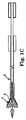
上述したように、外側シースまたはカテーテルは、従来から自己展開型血管ステントの送達のために用いられている。このような技術を自己展開型ステント補綴心臓弁の送達に適用した場合、完全展開においては、補綴具に関連する径方向の高い拡張力は問題にならない。なぜならば、完全展開においては、補綴心臓弁の展開を可能にするために外側シースは張力によって退避するだけだからである。ところが、前記従来の送達装置を作動させて前記外側シースを前記補綴具に相対して部分的に退避させた場合、前記補綴具の相応に露出した遠位領域が拡張する一方、近位領域は前記送達装置に接続されたままである。理論的には、前記外側シースを前進させて、前記拡張領域を遠位方向から再捕獲するだけでよい。しかし、残念なことに、従来のシース構成の場合、シースを遠位方向からスライドさせることによってステント補綴心臓弁の拡張領域を収縮しようとすると、成功しないことが多い。すなわち、従来の送達シースの場合、補綴具の拡張領域の径方向の力に容易に打ち勝つことがてきない。なぜならば、前記シースは実際は収縮状態になっており、前記シースの急峻な縁部に少なくとも部分的に起因して圧潰し、その結果、補綴具の拡張領域上を満遍なくスライドすることができなくなる。このような状態を、図1A〜図1Cに簡略して示す。展開前の状態(図1A)においては、ステント補綴心臓弁Pは、シースS内において拘束されており、シースSを支持している。展開状態(図1B)においては、シースSは遠位方向に退避しており、補綴具Pは部分展開している。前記シースを遠位方向にスライドさせることによって補綴具Pを「再捕獲」することが試行された場合(図1C)、シースSの先端Eが補綴具Pの拡大した直径に高速衝突し、その結果、遠位端Eは補綴具P上を容易にスライドできなくなる。さらに、シースSは内部から支持されなくなり、補綴具Pによる径方向の拡張付勢により、シースSは圧屈または圧潰する。 As mentioned above, outer sheaths or catheters are traditionally used for the delivery of self-expanding vascular stents. When such a technique is applied to the delivery of a self-expanding stent prosthetic heart valve, the high radial expansion force associated with the prosthesis is not a problem in full deployment. This is because in full deployment, the outer sheath is simply retracted by tension to allow deployment of the prosthetic heart valve. However, when the conventional delivery device is actuated to partially retract the outer sheath relative to the prosthesis, the correspondingly exposed distal region of the prosthesis expands, while the proximal region Stay connected to the delivery device. Theoretically, the outer sheath need only be advanced to recapture the dilated region from the distal direction. Unfortunately, with conventional sheath configurations, attempts to contract the expanded region of the stent prosthetic heart valve by sliding the sheath from the distal direction are often unsuccessful. That is, conventional delivery sheaths cannot easily overcome the radial force of the expanded region of the prosthesis. This is because the sheath is actually in a contracted state and collapses due at least in part to the steep edge of the sheath so that it cannot slide evenly over the expanded region of the prosthesis. Such a state is simply shown in FIGS. 1A to 1C. In the state before deployment (FIG. 1A), the stent prosthetic heart valve P is restrained in the sheath S and supports the sheath S. In the deployed state (FIG. 1B), the sheath S is retracted in the distal direction, and the prosthesis P is partially deployed. When an attempt is made to “recapture” the prosthesis P by sliding the sheath distally (FIG. 1C), the tip E of the sheath S collides with the enlarged diameter of the prosthesis P at a high speed, As a result, the distal end E cannot easily slide on the prosthesis P. Furthermore, the sheath S is no longer supported from the inside, and the sheath S is crushed or crushed by the radial expansion bias by the prosthesis P.
上記を鑑みて、心臓弁移植に関連する制約を満たしかつ補綴具の部分的展開および再捕獲を可能にする、ステント経カテーテル補綴心臓弁送達システム、装置および方法が必要とされている。 In view of the above, there is a need for a stent transcatheter prosthetic heart valve delivery system, apparatus and method that satisfies the limitations associated with heart valve implantation and allows partial deployment and recapture of the prosthesis.
本開示の原理に関連するいくつかの態様は、ステント補綴心臓弁を経皮的に展開させるための送達システムに関連する。前記補綴心臓弁は、径方向に自己拡張可能であり、収縮配置構成から通常配置構成となる。前記送達装置は、内側シャフトアセンブリと、送達シースカプセルと、再捕獲用シースとを含む。前記内側シャフトアセンブリは、中間領域を含む。前記中間領域によって提供される接続構造は、ステント補綴心臓弁と選択的に係合するように構成される。前記送達シースカプセルは、前記内側シャフトアセンブリ上にスライド可能に配置され、ステント補綴心臓弁を収縮保持するように構成される。前記再捕獲用シースは、前記内側シャフトアセンブリ上にスライド可能に配置され、ファネルセグメントを含む。前記ファネルセグメントは、シャフトから遠位方向に延びる。前記ファネルセグメントは、複数の円周方向に間隔を空けて配置されたランナーと、ポリマーオーバーレイとを含む。これらのランナーはそれぞれ、第1の端部において前記シャフトに取り付けられ、前記シャフトの反対側の遠位端において終端する。前記ポリマーオーバーレイは、前記ランナーを包囲する。この点について、前記オーバーレイは、前記シャフトに接合されるが、少なくとも前記遠位端には接合されない。前記ファネルセグメントは、通常状態から拡張状態へと移行することができる。前記拡張状態において、前記ファネルセグメントは、ファネル形状を有する。前記ファネル形状の直径は、遠位方向において増加する。さらに、前記ファネルセグメントは、前記拡張状態から前記通常状態へと自己移行可能である。この構造により、前記送達装置は、送達状態を提供するように構成される。前記送達状態において、前記カプセルにより、ステント補綴心臓弁は前記内側シャフトアセンブリ上において収縮保持され、前記ファネルセグメントは前記補綴心臓弁から長手方向に変位する。使用時において、前記ファネルセグメントを用いて、再捕獲動作の一環として、前記補綴心臓弁の部分展開領域上の前記カプセルのスライド移動を促進することができる。いくつかの実施形態において、前記再捕獲用シースは、送達シースカプセルと別個に提供され、前記送達シースカプセルと前記内側シャフトアセンブリとの間においてスライド可能に配置される。他の実施形態において、前記ファネルセグメントは、前記送達シースカプセルからの遠位延長部として形成され、前記ファネルセグメントは前記送達状態において前記補綴心臓弁の遠位において配置される。それにも関わらず、前記ランナーによって前記ファネルセグメントの円柱型強度が得られ、前記オーバーレイは、内部拡張力を受けたとき(例えば、前記ファネルセグメントが部分展開状態の補綴心臓弁上をスライドした際)、前記ファネルセグメントの形状を制御する。 Some aspects related to the principles of the present disclosure relate to a delivery system for percutaneously deploying a stent prosthetic heart valve. The prosthetic heart valve is self-expandable in the radial direction and changes from a contracted configuration to a normal configuration. The delivery device includes an inner shaft assembly, a delivery sheath capsule, and a recapture sheath. The inner shaft assembly includes an intermediate region. The connection structure provided by the intermediate region is configured to selectively engage a stent prosthetic heart valve. The delivery sheath capsule is slidably disposed on the inner shaft assembly and is configured to hold the stent prosthetic heart valve contracted. The recapture sheath is slidably disposed on the inner shaft assembly and includes a funnel segment. The funnel segment extends distally from the shaft. The funnel segment includes a plurality of circumferentially spaced runners and a polymer overlay. Each of these runners is attached to the shaft at a first end and terminates at the distal end opposite the shaft. The polymer overlay surrounds the runner. In this regard, the overlay is joined to the shaft but not at least to the distal end. The funnel segment can transition from a normal state to an expanded state. In the expanded state, the funnel segment has a funnel shape. The funnel-shaped diameter increases in the distal direction. Furthermore, the funnel segment is capable of self-transition from the expanded state to the normal state. With this structure, the delivery device is configured to provide a delivery state. In the delivery state, the capsule keeps the stent prosthetic heart valve contracted on the inner shaft assembly and the funnel segment is displaced longitudinally from the prosthetic heart valve. In use, the funnel segment can be used to facilitate sliding movement of the capsule over a partially deployed region of the prosthetic heart valve as part of a recapture operation. In some embodiments, the recapture sheath is provided separately from the delivery sheath capsule and is slidably disposed between the delivery sheath capsule and the inner shaft assembly. In another embodiment, the funnel segment is formed as a distal extension from the delivery sheath capsule, and the funnel segment is positioned distal to the prosthetic heart valve in the delivery state. Nevertheless, the runner provides columnar strength of the funnel segment and the overlay is subjected to internal expansion force (eg, when the funnel segment slides over a partially deployed prosthetic heart valve). , Controlling the shape of the funnel segment.
本開示の原理によるさらに他の局面は、患者の心臓弁の修復(例えば、交換)を行うためのシステムに関連する。前記システムは、送達装置と、補綴心臓弁とを含む。前記送達装置は、上述したように、内側シャフトアセンブリと、送達シースカプセルと、ファネルセグメントを含む再捕獲用シースとを含む。前記補綴心臓弁は、ステントフレームと、前記フレームに取り付けられた少なくとも2つの弁尖を形成する弁構造とを有する。前記補綴心臓弁は、収縮配置構成から通常配置構成へと自己拡張可能することができる。この構造により、前記システムは、装填モードと、部分展開モードと、再捕獲モードとの間において移行可能なように構成される。前記装填モードにおいて、前記補綴心臓弁は前記内側シャフトアセンブリの中間領域に接続され、前記カプセルは、前記補綴心臓弁を前記収縮配置構成において収縮保持する。さらに、前記ファネルセグメントは、長手方向において前記補綴心臓弁から間隔を空けて配置される。前記部分展開モードにおいて、前記カプセルを前記補綴心臓弁から部分的に退避させると、前記補綴心臓弁の遠位領域が前記カプセルに相対して露出し、自己拡張する。前記再捕獲モードにおいて、前記ファネルセグメントは前記カプセルから遠位方向に配置され、前記補綴心臓弁の遠位露出領域に沿っており、その結果、前記ファネルセグメントは前記拡張状態に向かって拡張する。 Yet another aspect in accordance with the principles of the present disclosure relates to a system for performing a repair (eg, replacement) of a patient's heart valve. The system includes a delivery device and a prosthetic heart valve. The delivery device includes an inner shaft assembly, a delivery sheath capsule, and a recapture sheath that includes a funnel segment, as described above. The prosthetic heart valve has a stent frame and a valve structure forming at least two leaflets attached to the frame. The prosthetic heart valve can be self-expandable from a contracted configuration to a normal configuration. With this structure, the system is configured to be able to transition between a loading mode, a partially deployed mode, and a recapture mode. In the loading mode, the prosthetic heart valve is connected to an intermediate region of the inner shaft assembly, and the capsule holds the prosthetic heart valve deflated in the deflated configuration. Further, the funnel segment is spaced from the prosthetic heart valve in the longitudinal direction. In the partially deployed mode, when the capsule is partially retracted from the prosthetic heart valve, the distal region of the prosthetic heart valve is exposed relative to the capsule and self-expands. In the recapture mode, the funnel segment is disposed distally from the capsule and is along the distal exposed region of the prosthetic heart valve so that the funnel segment expands toward the expanded state.
本開示の原理によるさらに他の局面は、ステント補綴心臓弁を移植部位へと展開させる方法に関連する。前記方法は、径方向に拡張可能な補綴心臓弁が装填された送達装置を受容するステップを含む。前記径方向に拡張可能な補綴心臓弁が有するステントフレームには、弁構造が取り付けられる。前記送達装置は、送達シースカプセルと、再捕獲用シースとを含む。前記送達シースカプセルは、収縮配置構成の前記補綴心臓弁を送達状態の内側シャフトアセンブリ上において収縮的に収容する。前記再捕獲用シースは、ファネルセグメントを含む。前記ファネルセグメントは、前記内側シャフトアセンブリ上においてスライド可能に配置される。前記送達状態において、前記ファネルセグメントは、長手方向において前記補綴心臓弁から間隔を空けて配置される。前記補綴心臓弁は、前記収縮配置構成において、患者の内腔を通じて前記送達状態の前記送達装置を介して移植部位へと送達される。前記カプセルは、前記補綴心臓弁に相対して近位方向に退避し、これにより、前記補綴心臓弁の遠位領域は前記カプセルの遠位において露出する。前記露出した遠位領域は、自己拡張して通常配置構成となる。前記部分展開された補綴心臓弁の前記移植部位への相対位置を評価する。前記評価に基づいて、前記再捕獲用シースを前記補綴心臓弁に相対して遠位方向に前進させ、これにより、前記ファネルセグメントが前記カプセルから遠位に移動し、前記ファネルセグメントは、前記補綴心臓弁の遠位領域と接触した結果拡張してファネル形状となる。前記ファネルセグメントを前記補綴心臓弁の遠位領域上において遠位方向に前進させる。その後、前記カプセルを前記補綴心臓弁上に配置して、前記遠位領域を再度、移行させて、前記カプセル内の圧潰配置構成へと戻す。最後に、前記カプセルおよび前記ファネルセグメントを前記補綴心臓弁から完全に近位方向に退避させ、これにより、前記補綴心臓弁は前記内側シャフトアセンブリから展開する。いくつかの実施形態において、前記再捕獲用シースは、前記送達シース内にスライド可能に配置され、これにより、前記部分展開された補綴心臓弁を再捕獲するステップは、前記ファネルセグメントを前記補綴心臓弁上にスライドさせた後、前記カプセルを前記ファネルセグメント上にスライドさせるステップを含む。他の実施形態において、前記ファネルセグメントは、前記カプセルからの遠位延長部として設けられ、これにより、前記補綴心臓弁を再捕獲するステップは、前記ファネルセグメントを前記補綴心臓弁上において連続的にスライドさせた後、前記カプセルを前記補綴心臓弁上においてスライドさせるステップを含む。 Yet another aspect according to the principles of the present disclosure relates to a method of deploying a stent prosthetic heart valve to an implantation site. The method includes receiving a delivery device loaded with a radially expandable prosthetic heart valve. A valve structure is attached to a stent frame included in the radially expandable prosthetic heart valve. The delivery device includes a delivery sheath capsule and a recapture sheath. The delivery sheath capsule contractively houses the prosthetic heart valve in a contracted configuration on a delivered inner shaft assembly. The recapture sheath includes a funnel segment. The funnel segment is slidably disposed on the inner shaft assembly. In the delivery state, the funnel segment is spaced longitudinally from the prosthetic heart valve. The prosthetic heart valve is delivered to the implantation site through the delivery device in the delivered state through the lumen of the patient in the contracted configuration. The capsule retracts proximally relative to the prosthetic heart valve, thereby exposing a distal region of the prosthetic heart valve distal to the capsule. The exposed distal region is self-expanding into a normal configuration. The relative position of the partially deployed prosthetic heart valve to the implantation site is evaluated. Based on the evaluation, the recapture sheath is advanced distally relative to the prosthetic heart valve, thereby moving the funnel segment distally from the capsule, and the funnel segment is Expands into a funnel shape as a result of contact with the distal region of the heart valve. The funnel segment is advanced distally over the distal region of the prosthetic heart valve. The capsule is then placed over the prosthetic heart valve and the distal region is transitioned again to return to the collapsed configuration within the capsule. Finally, the capsule and funnel segment are retracted completely proximally from the prosthetic heart valve, thereby deploying the prosthetic heart valve from the inner shaft assembly. In some embodiments, the recapture sheath is slidably disposed within the delivery sheath such that recapturing the partially deployed prosthetic heart valve causes the funnel segment to move the prosthetic heart. Sliding the capsule onto the funnel segment after sliding on the valve. In another embodiment, the funnel segment is provided as a distal extension from the capsule, whereby recapturing the prosthetic heart valve continuously moves the funnel segment over the prosthetic heart valve. Sliding the capsule over the prosthetic heart valve after sliding.
現在の経カテーテル心臓弁送達装置の場合、経カテーテル弁を展開後に順行方向または逆行方向に再配置することができない。本開示の送達装置は、これらの問題を解消し、臨床医が補綴心臓弁を部分展開させ、その後前記補綴心臓弁を解放する前に前記補綴心臓弁を再捕獲および再配置または除去することを可能にする。一般的には、前記装置は、ファネルセグメントを有する再捕獲用シースを提供することにより、機能する。前記再捕獲用シースは、前記送達シースカプセルと、部分展開補綴具の拡張領域との間の移行として機能し、これにより、前記部分展開された補綴心臓弁を前記送達シースカプセル内に入れて再捕獲をする。 With current transcatheter heart valve delivery devices, the transcatheter valve cannot be repositioned in the antegrade or retrograde direction after deployment. The delivery device of the present disclosure eliminates these problems and allows a clinician to partially deploy the prosthetic heart valve and then recapture and reposition or remove the prosthetic heart valve before releasing the prosthetic heart valve. to enable. In general, the device works by providing a recapture sheath with funnel segments. The recapture sheath functions as a transition between the delivery sheath capsule and the expanded region of the partially deployed prosthesis, thereby reinserting the partially deployed prosthetic heart valve into the delivery sheath capsule. Capture.
本明細書中用いられるステント補綴心臓弁は、本開示の多様なシステム、装置および方法に従って用いられ、また、多様な異なる構成を含み得る(例えば、組織弁尖を有する生体弁またはポリマー弁尖、金属弁尖または培養組織弁尖を有する補綴心臓弁)。また、本明細書中用いられるステント補綴心臓弁は、任意の心臓弁の代替物として特に構成され得る。よって、本開示のシステム、装置および方法において有用なステント補綴心臓弁は一般的には、ネイティブ大動脈、僧帽、肺動脈または三尖弁の代替物として静脈弁として用いられ得、あるいは、不具合のあるバイオ補綴具(例えば、大動脈弁または僧帽弁の領域内のもの)の代替物として用いられ得る。 As used herein, stent prosthetic heart valves are used in accordance with the various systems, devices and methods of the present disclosure and can include a variety of different configurations (eg, biological or polymer leaflets with tissue leaflets, Prosthetic heart valves with metal or cultured tissue leaflets). Also, the stent prosthetic heart valve used herein can be specifically configured as an alternative to any heart valve. Thus, stent prosthetic heart valves useful in the systems, devices and methods of the present disclosure can generally be used as venous valves as a replacement for native aorta, mitral, pulmonary artery or tricuspid valve or are faulty It can be used as an alternative to bioprosthetic devices (eg, in the area of aortic or mitral valves).
一般的に、本開示のステント補綴心臓弁は、弁構造(組織または人工)を維持するステントまたはステントフレームを含む。前記ステントは、自然または通常構成および拡張配置構成を有し、圧潰可能となって収縮配置構成となり、その結果前記送達装置内に搭載される。前記ステントは通常は、前記送達装置から放出されたときに自己展開または自己拡張するように構成される。例えば、本開示と共に有用に用いられるステント補綴心臓弁は、CoreValve(登録商標)(製造元:Medtronic Core Valve,LLC)という商標名で市販されている補綴具弁であり得る。本開示のシステム、装置および方法と共に有用に用いられる経カテーテル心臓弁補綴具の他の非限定的な例について、米国公開第2006/0265056号、第2007/0239266号および第2007/0239269号に記載がある。本明細書中、同文献の教示内容を参考のため援用する。ステントまたはステントフレームは支持構造であり、複数の支柱またはワイヤ部を含む。前記複数の支柱またはワイヤ部は、相互に配置されて、所望の収縮率および強度を前記補綴心臓弁に提供する。一般的に、本開示のステントまたはステントフレームは概して管状の支持構造であり、前記支持構造の内部領域において弁構造弁尖が固定される。これらの弁尖は、多様な材料から形成することができる(例えば、自己組織、キセノグラフ材料、または人工材料が当該分野において公知である)。前記弁尖は、均質な生物学的弁構造として提供され得る(例えば、豚弁、ウシ弁またはウマ弁)。あるいは、前記弁尖は、相互に独立して提供することもできる(例えば、ウシまたはウマ心膜外弁尖)、その後、ステントフレームの支持構造に組み付けることができる。別の例において、ステントフレームおよび弁尖を同時に製造することができる(例えば、高度バイオ補綴具表面(ABPS)に生成された高強度ナノ製造NiTi膜を用いて達成可能なもの)。ステントフレーム支持構造は一般的には、少なくとも2つ(典型的には3つ)の弁尖に対応するように構成される。しかし、本明細書中に記載する種類の代替用補綴心臓弁において、3つよりも多数または少数の弁尖を取り入れることが可能である。 In general, the stent prosthetic heart valves of the present disclosure include a stent or stent frame that maintains the valve structure (tissue or prosthesis). The stent has a natural or normal configuration and an expanded configuration and is collapsible into a contracted configuration, so that it is loaded into the delivery device. The stent is typically configured to self-expand or self-expand when released from the delivery device. For example, a stent prosthetic heart valve usefully used with the present disclosure may be a prosthetic valve marketed under the trademark CoreValve® (manufacturer: Medtronic Core Valve, LLC). Other non-limiting examples of transcatheter heart valve prostheses usefully used with the systems, devices and methods of the present disclosure are described in US Publication Nos. 2006/0265056, 2007/0239266, and 2007/0239269. There is. In the present specification, the teaching content of this document is incorporated by reference. A stent or stent frame is a support structure and includes a plurality of struts or wire portions. The plurality of struts or wire portions are placed together to provide the desired prosthetic heart valve with the desired contraction rate and strength. In general, the stent or stent frame of the present disclosure is a generally tubular support structure with a valve structure leaflet secured in an interior region of the support structure. These leaflets can be formed from a variety of materials (eg, self-organized, xenograph materials, or artificial materials are known in the art). The leaflets can be provided as a homogeneous biological valve structure (eg, a pig valve, a bovine valve or an equine valve). Alternatively, the leaflets can be provided independently of each other (eg, bovine or equine epicardial leaflets) and then assembled to the support structure of the stent frame. In another example, a stent frame and leaflets can be manufactured simultaneously (eg, achievable using a high strength nanofabricated NiTi film generated on an advanced bioprosthetic surface (ABPS)). The stent frame support structure is generally configured to accommodate at least two (typically three) leaflets. However, it is possible to incorporate more or fewer leaflets than three in alternative prosthetic heart valves of the type described herein.
ステントフレームのいくつかの実施形態は、一連のワイヤまたはワイヤセグメントであり得る。これらのワイヤまたはワイヤセグメントは、収縮配置構成または圧潰配置構成から通常の径方向に拡張した配置構成へと自己移行することが可能なように、配置される。いくつかの構造において、ステントフレーム支持構造を含む複数の個々のワイヤは、金属または他の材料によって形成することができる。これらのワイヤは、ステントフレーム支持構造によって折り畳みまたは収縮またはクリンプを可能とすることで収縮配置構成が得られるように、配置される。前記収縮配置構成における内径は、通常の拡張配置構成における内径よりも小さい。前記圧潰配置構成において、弁が取り付けられたステントフレーム支持構造を送達装置に取り付けることができる。これらのステントフレーム支持構造は、所望のときに(例えば1つ以上のシースをステントフレームの長さに相対して移動させることにより、)通常の拡張配置構成に変更可能なように、構成される。 Some embodiments of the stent frame may be a series of wires or wire segments. These wires or wire segments are arranged so that they can self-transfer from a contracted or collapsed arrangement to a normal radially expanded arrangement. In some constructions, the plurality of individual wires including the stent frame support structure can be formed of metal or other material. The wires are positioned so that a contracted configuration is obtained by allowing the stent frame support structure to be folded or contracted or crimped. The inner diameter in the contracted arrangement is smaller than the inner diameter in a normal expanded arrangement. In the collapsed configuration, a stent frame support structure with a valve attached thereto can be attached to the delivery device. These stent frame support structures are configured such that they can be changed to a normal expanded configuration when desired (eg, by moving one or more sheaths relative to the length of the stent frame). .
本開示の実施形態におけるステントフレーム支持構造のワイヤは、形状記憶材料から形成することができる(例えば、ニッケルチタン合金(例えば、Nitinol(登録商標))。この材料を前記支持構造に用いることで、(例えば熱、エネルギーなどの付加または外力(例えば、収縮力)の除去によって)前記支持構造を自己拡張させて、収縮配置構成から通常の拡張配置構成へと変化させることが可能となる。このステントフレーム支持構造は、ステントフレームの構造の損傷を引き起こすことなく、複数回にわたって収縮および再拡張させることも可能である。加えて、このような実施形態のステントフレーム支持構造は、単一材料からレーザー切断することもできるし、あるいは、複数の異なるコンポーネントから組み立てることも可能である。これらの種類のステントフレーム構造について、使用可能な送達装置の一例は、退避可能シースを備えたカテーテルを含む。前記退避可能シースは、カテーテル展開までステントフレームを被覆する。カテーテル展開時において、前記シースを退避させることで、前記ステントフレームを自己拡張させることができる。このような実施形態さらなる詳細について、以下に説明する。 The wire of the stent frame support structure in embodiments of the present disclosure can be formed from a shape memory material (e.g., nickel titanium alloy (e.g., Nitinol <(R)>) using this material for the support structure, The support structure can be self-expanded (e.g., by the addition of heat, energy, etc. or the removal of an external force (e.g., contraction force)) to change from a contracted configuration to a normal expanded configuration. The frame support structure can also be contracted and re-expanded multiple times without causing damage to the structure of the stent frame.In addition, the stent frame support structure in such embodiments can be made from a single material to a laser. Can be cut or assembled from several different components For these types of stent frame structures, an example of a delivery device that can be used includes a catheter with a retractable sheath that covers the stent frame until catheter deployment. The stent frame can be self-expanded by retracting the sheath, and further details of such embodiments are described below.
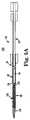
上記を念頭において、本開示の原理による経カテーテルステント補綴心臓弁送達装置30の一実施形態を図2に示す。装置30は、再捕獲用シース32と、内側シャフトアセンブリ34と、送達シースアセンブリ36と、ハンドル38を主に含む。これらの多様なコンポーネントの詳細について、以下に記載する。しかし、一般的にいえば、送達装置30は、ステント補綴心臓弁(図示せず)と組み合わされることで、患者の不全のある心臓弁の修復(例えば、交換)を行うためのシステムを形成する。送達装置30は、典型的な送達状態を与え、前記送達状態において、前記ステント補綴心臓弁は、内側シャフトアセンブリ34に接続され、送達シースアセンブリ36のカプセル40内において収縮保持される。送達シースアセンブリ36を操作することで、カプセル40を(ハンドル38の動作を介して)補綴心臓弁から近位方向に退避させることができ、その結果、補綴具を自己拡張させることができ(あるいは、拡張させることができ)、前記補綴具を内側シャフトアセンブリ34から放出させることができる。さらに、ハンドル38を操作することで、再捕獲用シース32を内側シャフトアセンブリ34および送達シースアセンブリ36に相対して操作して、再捕獲用シース32のファネルセグメント42を遠位方向にカプセル40を越えて補綴心臓弁の部分展開領域上に配置することができ、これにより、カプセル40内における補綴具の再捕獲が促進される。 With the above in mind, one embodiment of a transcatheter stent prosthetic heart
図2中に示し、かつ以下に説明するコンポーネント32〜38の多様な機能は、異なる構造および/または機構と変更または交換することができる。よって、本開示は、図示および記載のような内側シャフトアセンブリ34、送達シースアセンブリ36、ハンドル38などにも制限されない。より一般的には、本開示による送達装置は、自己展開型のステント補綴心臓弁(例えば、カプセル40)と、補綴具の解放または展開の実行(例えば、カプセル40の退避)が可能な機構と、再捕獲を促進するファネル型構造(例えば、ファネルセグメント42)とを収縮保持することが可能な機能を提供する。 The various functions of the components 32-38 shown in FIG. 2 and described below can be changed or replaced with different structures and / or mechanisms. Thus, the present disclosure is not limited to the
再捕獲用シース32は、ファネルセグメント42およびシャフト50を含む。ファネルセグメント42は、シャフト50から遠位方向に延びる。再捕獲用シース32は、ルーメン52(主に参照符号によって示す)を形成する。ルーメン52は、内側シャフトアセンブリ34上においてスライド可能に受入れられるようなサイズにされ、再捕獲用シース32は、遠位端54で終端する。図2の1つの構造により、再捕獲用シース32は、送達シースアセンブリ36から離隔して配置され、内側シャフトアセンブリ34と送達シースアセンブリ36との間においてスライド可能に受容されるようなサイズにされる。以下に記載する他の実施形態において、再捕獲用シース32は、送達シースアセンブリ36の一部として提供され、ファネルセグメント42は、カプセル40からの遠位延長部として形成される。 The recapture
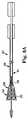
ファネルセグメント42は、(例えば、内側方向に付加される径方向拡張力に応答して)図2の通常状態または弛緩状態から拡張状態へと径方向に拡張可能なように、構成される。前記通常状態または弛緩状態において、直径は比較的小型でありかつ比較的均一である(例えば、均一な直径の円筒または管に類似する形状)。前記拡張状態において、フランジまたはファネル状の形状となり、遠位端54の直径は、(前記通常状態と比較して)径方向に増加する。前記拡張力が無くなると、ファネルセグメント42は、自己移行して、前記拡張状態から再度、前記通常状態となるかまたは前記拡張状態から前記通常状態となる。図3Aおよび図3Bに最良に示すように、いくつかの実施形態において、ファネルセグメント42は、複数の円周方向に間隔を空けて配置されたランナー60と、ポリマーオーバーレイ62とを含む。図3A〜図3C中、説明をし易くするために、ランナー60およびオーバーレイ62の厚さを誇張して図示している。さらに、オーバーレイ62が透明である様子が図示されており、これにより、ランナー60のうちいくつかが図3Aおよび図3C中のオーバーレイ62の「後側」または「内部」にある様子を視認することが可能となる。これらのランナー60は、いくつかの構造において同一であり、各ランナー60は、シャフト50に取り付けられた第1の端部64を有し、シャフト50と反対側の遠位端66において終端する。ポリマーオーバーレイ62は、ランナー60を包囲し、ランナー60が移行するかまたは撓んで図3Aおよび図3Bの通常状態から図3Cの拡張状態へと変化するのを制御する。その結果、ランナー60は、形状記憶特性をファネルセグメント42に付与し、以下に説明するように、ファネルセグメント42を図3Cの拡張状態から図3Aの通常状態へと自己移行させる。
いくつかの実施形態において、これらのランナー60は、可撓性の金属片(例えば、肉薄のステンレススチールまたはNiTi片)として形成される。ランナー60の形状および構造は、ランナー60がそれぞれ通常時において(例えば付与された形状記憶特性を介して)比較的直線状または平坦な形状をとるような、形状および構造である。各ランナー60の第1の端部64は、多様な様態(例えば、接着、溶接など)でシャフト50に取り付けることができる。シャフト50およびオーバーレイ62を除いて、これらのランナー60は相互接続されていない。よって、ランナー60は、特に各遠位端66において、オーバーレイ62によって可能となる範囲まで相互に自由に撓むことができ、その結果、シャフト50との取り付けポイントにおいて撓む。 In some embodiments, these
ファネルセグメント42は、2つ以上のランナー60を含み得る。しかし、いくつかの実施形態において、ファネルセグメント42は、少なくとも4つのランナー60を含む。これらのランナー60は、シャフト50の円周周囲において、任意選択的に相互に等間隔を空けて配置される。図示のように、いくつかの構造において、遠位端66は丸い形状であるが、他の形状も可能である。ランナー60は、多様な異なる寸法を持ち得る。いくつかの実施形態において、各ランナー60の厚さは0.005〜0.015インチであり、各ランナー60は、シャフト50から対応する遠位端66へと延び、その長さは、0.20〜1.0インチである。
オーバーレイ62は、外科的に安全な適合ポリマー材料であるか、または、ランナー60の周囲を包囲しかつシャフト50に接着された膜である。例えば、オーバーレイ62は、ナイロンまたは他のアミドブロックポリマー、ウレタン、ポリエステル、脂肪族ポリアミド、ポリエーテルおよびポリアミドの共重合体、スルホンアミド可塑剤、熱可塑性ポリエーテルウレタン、低密度ポリエチレンまたは鎖状低密度ポリエチレン(架橋または非架橋を問わない)を含有する可塑化ポリアミドであり得るかまたはこれらを含み得る。オーバーレイ材料(単数または複数)は、二軸配向であり得る。さらに、オーバーレイ62は、単一層構造、2層構造または多層構造を持ち得る。いくつかの実施形態において、オーバーレイ62は、シャフト50のランナー60の遠位において接合される。この構造により、オーバーレイ62により、ランナー60がオーバーレイ62内において自由に撓むかまたは拡張することが可能になり、これにより、図3Cの拡張状態においてファネル形状が集合的に形成および支持される。オーバーレイ62は弾性的に変形可能であり得、オーバーレイ62の抵抗により、ランナー60が連続して撓んで特定レベルを越えて撓むことが回避される。よって、オーバーレイ62により、拡張状態のファネル形状においてファネルセグメント62によって規定される長さおよび傾斜角度が制御される。その結果、ランナー60により、オーバーレイ62およびよってファネルセグメント42の拡張を可能にしつつ、オーバーレイ62内の円柱型強度が得られる。
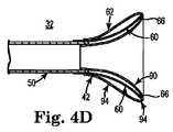
一実施形態において、オーバーレイ62は、初期においては肉薄壁を有するバルーンとして提供される。このバルーンそのものは、ランナー60を収容するように転用される。例えば、図4A〜図4Dは、本開示のいくつかの実施形態によるファネルセグメント42(図3A)の構造を示す。先ず、図4Aに示すように、バルーン70の構造が形成または提供される。この構造は、中間部72と、対向する第1の端部74aおよび第二の端部74bとを有する。バルーン構造70は、例えば中間部72が得られるようにポリマー管を集中的に膨張させることにより、得ることができる。中間部72は、端部74aおよび74bと比較してより大きな内径および外径を有し、中点76か端部74aおよび74bへと直径がテーパー付けされる。基準点として、端部74aおよび74bは、シャフト50(図3A)の内径および外径のそれぞれに適合するように任意選択的にサイズ設定される。シャフト50(図3A)には、その後オーバーレイ62が取り付けられる。よって、例えば、シャフト50が16フレンチシースである場合、第一の端部74aは、16フレンチシースの外径とほぼ同じサイズにされ得、第二の端部74bは、16フレンチシースの内径とほぼ同じサイズにされ得る(またはその逆もあり得る)。中間部72の最大直径は、シャフト50の外径よりも若干大きい(例えば、シャフト50が16フレンチシースである場合、中間部72の最大直径は、15〜20mmのオーダーである)。あるいは、他の寸法も可能である。 In one embodiment,
その後、バルーン構造70を図4Bに示すように逆転または折り畳む。詳細には、第二の端部74bは、軸方向に第一の端部74aに向かって方向付けられ、その結果、中間部72は、ほぼ中点76において折り畳まれる(図4A)。このような折り畳み地点を図4B中において参照番号78で示す。その後、折り畳まれたバルーン構造70は、切断線80に沿って切断される。切断線80は、折り畳まれたバルーン構造70の長さに沿って配置される。第一の端部74aの内径がシャフト50の外径とほぼ同じであり、第二の端部74bの外径がシャフト50の内径とほぼ同じである場合、折り畳まれたバルーン構造70の長さは、シャフト50の内径および外径(図3A)に対応する。 The
切断後、第二の端部74bの残り部分は、図4Cに示すように第一の端部74a内へとさらに折り畳まれる。その結果得られたオーバーレイ62は、内側管状壁部90および外側管状壁部92によって規定される。これらの内側管状壁部90および外側管状壁部92は、両者間に空間94を規定するように、配置される。これらの壁部90および92は反転部78から延び、内側壁部90は、内側端部96において終端する。内側端部96の直径は、シャフト50(図3A)の内径とほぼ同じである。シャフト50(図3A)には、オーバーレイ62がその後組み付けられる。外側壁部92は、外側端部98において終端する。外側端部98は、反転部78と反対側にあり、シャフト50の外径とほぼ等しい直径を有する。 After cutting, the remaining portion of the
図4Dを参照して、再捕獲用シース32の構造は、ランナー60を含む。これらのランナー60は、上述したようにシャフト50に取り付けられかつシャフト50から遠位方向に延びる。その後、このようにして組み立てられたランナー60をオーバーレイ62の空間94に挿入する。その後、オーバーレイ62をシャフト50に接合する。例えば、内側壁部90をシャフト50の内径に熱接合することができる。外側壁部92は、同様にシャフト50の外径に熱接合しかつ/またはランナー60それぞれの第1の端部64へと熱接合させることができる。しかし、いくつかの実施形態において、オーバーレイ62は、シャフト50の遠位においてランナー60に接合されない。他の構造において、オーバーレイ62は、シャフト50の遠位において1つ以上のランナー60の一部に接合され得るが、各ランナー60の少なくとも遠位端66は、オーバーレイ62へ接合されない。 With reference to FIG. 4D, the structure of the recapture
シャフト50は、シャフト50の移動に応答して発生するファネルセグメント42の所望のスライド移動を促進するような様態でファネルセグメント42を支持するための適切な任意の形態をとり得る。例えば、シャフト50は、熱可塑性エラストマー管であり得る(例えば、Pebax(登録商標))。シャフト50は、埋設編組材料層(例えば、ステンレススチールワイヤ)を任意選択的に含み得る。 The
再捕獲用シース32(特にファネルセグメント42)は、あるいは多様な他の様態で構築され得る。例えば、肉薄壁を有するポリマー管は、ランナー60を包囲し得る。それにも関わらず、最終構造において、ファネルセグメント42は、内部拡張力に応答して、図3Aの通常状態から図3Cの拡張状態(および対応するファネル形状)に移行することができ、その後、ランナー60からファネルセグメント42へと集合的に付与された形状記憶特性に少なくとも部分的に起因して内部拡張力が無くなると、ファネルセグメント42は自己移行して再度、前記通常状態に戻る。 The recapture sheath 32 (especially funnel segment 42) may alternatively be constructed in a variety of other ways. For example, a polymer tube having a thin wall can surround the
図2に戻って、送達装置30の残りのコンポーネント34〜38は、ステント自己拡張型補綴心臓弁を経皮的に送達および展開するのに適した多様な形態をとり得る。例えば、内側シャフトアセンブリ34は、ステント補綴心臓弁をカプセル40内において支持するのに適した多様な構造を持ち得る。いくつかの実施形態において、内側シャフトアセンブリ34は、保持部材100と、中間管102と、近位管104とを含み得る。一般的に、保持部材100はプランジャーに類似し得、以下に説明するようにステント補綴心臓弁をカプセル40内に保持するための機能を含む。管102は、保持部材100を近位管104へと接続し、その結果、近位管104は、内側シャフトアセンブリ34をハンドル38へと接続させる。コンポーネント100〜104を組み合わせることで、連続ルーメン106(主に参照符号によって示す)を規定することができる。連続ルーメン106は、補助コンポーネント(例えば、ガイドワイヤ(図示せず))を受いれるようなサイズにされる。 Returning to FIG. 2, the remaining components 34-38 of the
保持部材100は、先端110と、支持管112と、ハブ114とを含み得る。先端110は、ノーズコーンを形成または規定する。前記ノーズコーンは、遠位方向に傾斜した外面を有する。この外面は、身体組織との無傷接触を促進するように、適合される。先端110は、支持管112に固定可能であるかまたは支持管112に相対してスライド可能である。支持管112は、先端110から近位方向に延び、主に支持管112上に配置された収縮状態のステント補綴心臓弁を内部から支持するように構成される。支持管112は、選択された補綴心臓弁の寸法的特性に対応する長さおよび外径を有する。ハブ114は、先端110の反対側の支持管112へと取り付けられ(例えば、接着剤)、接続構造120(主に参照符号によって示す)を提供する。接続構造120は、補綴心臓弁の対応する機能を選択的に獲得するように、構成される。接続構造120は、多様な形態をとり得、内側シャフトアセンブリ34の中間部に沿って概して配置される。いくつかの構造において、接続構造120は、1つ以上の指部を含む。これらの指部は、補綴心臓弁ステントフレームによって形成された対応するアパチャ内に受容されるようなサイズにされる(例えば、前記補綴心臓弁ステントフレームは、その近位端部においてワイヤループを形成し得、これらのワイヤループは、カプセル40内において収縮されると、前記指部それぞれの上において受容される)。他の解放可能な接続配置構成も可能である(例えば、ハブ114によって形成された1つ以上の溝部を、補綴心臓弁の対応するコンポーネント(単数または複数)(例えば、ステントフレームの棒部または脚セグメント)をスライド可能に受容できるようなサイズにする)。さらに、内側シャフトアセンブリ34は、ステント弁の一時的保持を支援するさらなる構造および/または機構を含み得る(例えば、接続構造120上において付勢される管状スリーブ)(例えば、米国仮出願シリアル番号第61/237,373号(名称:「Transcatheter Valve Delivery Systems and Methods」、出願日:2009年8月27日)に記載のもの)。本明細書中、同文献の教示内容全体を参考のため援用する。 The retaining member 100 can include a
中間管102は、可撓性ポリマー材料(例えば、PEEK)で形成され、送達シースアセンブリ36内に受容されるようなサイズにされる。近位管104は、いくつかの実施形態において、先頭部122および終端部124を含み得る。先頭部122は、中間管102および近位管104間の移行部として機能し、よって、いくつかの実施形態において可撓性のポリマーチューブ(例えば、PEEK)である。この可撓性のポリマーチューブの直径は、中間管102の直径よりも若干小さい。終端部124は、より硬質な構造を有し、ハンドル38(例えば、金属ハイポチューブ)を用いた頑強なアセンブリが得られるように構成される。他の構造も可能である。例えば、他の実施形態において、中間管102および近位管104は、単一の均質な管または固体シャフトとして一体形成される。
送達シースアセンブリ36は、カプセル40および送達シースシャフト130を含み、近位端132および遠位端134を規定する。カプセル40は、送達シャフト130から遠位方向に延び、いくつかの実施形態において、(送達シャフト130の剛性と比較して)高剛性の構造を有する。このような高剛性構造により、収縮配置構成において予測されるステント補綴心臓弁の拡張力に十分に耐えるための十分な径方向剛性または円周方向剛性が得られる。例えば、送達シャフト130は、金属ブレードが埋設されたポリマー管であり得、カプセル40は、レーザー切断された金属管であり、ポリマー被覆部内に任意選択的に埋設される。あるいは、カプセル40および送達シャフト130は、より均一な構造(例えば、連続ポリマー管)を持ち得る。それにも関わらず、カプセル40は、カプセル40内に装填された際に所定直径においてステント補綴心臓弁を収縮保持するように構成される。送達シャフト130は、カプセル40をハンドル38へと接続するように機能する。送達シャフト130(およびカプセル40)は、患者の血管系を通過できるだけの十分な可撓性を有するように構成され、かつ、カプセル40の所望の軸方向移動を可能にするだけの十分な長手方向剛性を有する。換言すれば、送達シャフト130の近位退避は、カプセル40に直接反映され、その結果、これに対応してカプセル40が近位退避する。他の実施形態において、送達シャフト130は、カプセル40上への回転力または移動を伝達するように、さらに構成される。
ハンドル38は、ハウジング140および1つ以上のアクチュエータ機構142(主に参照符号によって示す)を主に含む。ハウジング140は、アクチュエータ機構(単数または複数)142を維持し、ハンドル38は、送達シースアセンブリ36の再捕獲用シース32および内側シャフトアセンブリ34に相対するスライド移動と、再捕獲用シース32の内側シャフトアセンブリ34および送達シースアセンブリ36に相対するスライド移動とを促進するように、構成される。ハウジング140は、ユーザが簡便に取り扱えるような任意の形状またはサイズを持ち得る。1つの簡単な構造において、第1の展開アクチュエータ機構142aは、ユーザーインターフェースまたはアクチュエータ144を含む。ユーザーインターフェースまたはアクチュエータ144は、スライド可能にハウジング140によって保持され、送達シースコネクタボディ146へと接続される。送達シースアセンブリ36の近位端132は、送達シースコネクタボディ146へと接続される。内側シャフトアセンブリ34(および特に近位管104)は、スライド可能に送達シースコネクタボディ146の通路148(主に参照符号によって示す)内において受容され、ハウジング140にリジッド接続される。第二の再捕獲用アクチュエータ機構142b(主に参照符号によって示す)も、同様にユーザーインターフェースまたはアクチュエータ150を含む。このユーザーインターフェースまたはアクチュエータ150は、移動可能な様態でハウジング140によって維持され、1つ以上のボディ(図示せず)を介して再捕獲用シース32へと接続される。これら1つ以上のボディ(図示せず)は、再捕獲用アクチュエータ150の動作と共に再捕獲用シース32が移動するのを促進する。この1つの受容可能な構造により、展開アクチュエータ144を操作して、送達シースアセンブリ36を再捕獲用シース32および内側シャフトアセンブリ34に相対して軸方向移動させることが可能となる。同様に、再捕獲用アクチュエータ150を操作して、再捕獲用シース32を内側シャフトアセンブリ34および送達シースアセンブリ36に相対して軸方向にスライドさせることが可能となる。 The handle 38 primarily includes a
図5Aは、本開示によるシステム158の簡単な図である。システム158は、患者の不全のある心臓弁の修復(例えば、交換または修復)のためのものであり、送達装置30内に装填されたステント補綴心臓弁160を含む。図5Aの送達装置30の送達状態において、補綴心臓弁160は、内側シャフトアセンブリ34上にクリンプされ、その結果、補綴心臓弁160は接続構造120と係合するする。カプセル40は、図示の収縮配置構成において補綴心臓弁160を収縮的に保持し、これにより、システム158の装填モードを規定する(システム158の「装填モード」は、送達状態の送達装置30に対応することが理解される)。最後に、再捕獲用シース32の遠位端54は補綴心臓弁160から長手方向に間隔を空けて配置され、ファネルセグメント42は、上述した通常状態をとる。例えば、図5Aに示す配置構成において、再捕獲用シース遠位端54は、補綴心臓弁160から近位方向に間隔を空けて配置される。その後、図5Aに示すように、カプセル40は、補綴心臓弁160(または装填モードにおいて補綴心臓弁160上に配置された再捕獲用シース32の他の任意の部分)を収縮配置構成内において(ファネルセグメント42の存在無しに)収縮的に保持できるだけの十分な構造的完全性を示す。 FIG. 5A is a simplified diagram of a
補綴心臓弁160を送達装置30から展開させるには(すなわち、システム158の展開モード)、例えばカプセル40を近位方向に退避させることでカプセル遠位端134が接続構造120の近位に移動させることにより、送達シースアセンブリ36を補綴心臓弁160上において退避させる。カプセル40が接続構造120の近位まで移動した後、補綴心臓弁160を自己拡張させて通常配置構成に変化させ、これにより、送達装置30から解放される。 To deploy the
いくつかの場合において、臨床医は、補綴心臓弁160を送達装置30から部分展開させた後に評価を行い、その後に補綴心臓弁160を完全解放することを望む場合がある。例えば、補綴心臓弁160が装填された送達装置30を、患者の損傷を受けた心臓弁の修復方法の一部として用いることができる。これらの状況下において、送達装置30を送達状態において(例えば逆行性アプローチにおいて)大腿動脈を経由して患者の下行大動脈内へと移動させることで、ネイティブ心臓弁移植標的部位へと前進させる。その後、送達装置30を透視下で大動脈弓から上行大動脈を通じて前進させ、不全のある大動脈弁を(大動脈弁代替目的のために)横断させる。送達装置30の位置決めを推定した後、図5Bに示すように、送達シースアセンブリ36(および詳細にはカプセル40)を補綴心臓弁160に相対して部分的に退避させる。このようにして、補綴具160の遠位領域170は、カプセル40に相対して外部露出し、自己拡張する。しかし、図5Bの部分展開モードにおいて、少なくとも補綴具160の近位領域172は、カプセル40内に拘束されたままであり、よって送達装置30へと接続される。このように送達装置30が部分展開された状態である場合、所望の移植部位に相対するステント補綴心臓弁160の位置を評価することができる。 In some cases, the clinician may wish to perform an evaluation after partial deployment of the
臨床医が上記評価に基づいて補綴具160を移植部位に相対して再配置する必要があると考えた場合、先ず、送達装置30を再捕獲状態へと移行させ(そしてシステム158を再捕獲モードを移行させることにより)、補綴心臓弁160を縮小させ、「再シース」する必要がでてくる。図5Cに示すように、再捕獲用シース32を、送達シースアセンブリ36に相対して遠位方向に前進させる。詳細には、ファネルセグメント42をカプセル40の遠位端134を越えて遠位方向に前進させて、補綴心臓弁160の露出遠位領域170と接触させる。オーバーレイ62(図3A)は、(少なくとも壁部の薄い厚さおよび遠位端54の拡張可能性に部分的に起因して)補綴心臓弁160の表面に沿って容易にスライドし、遠位端54は、遠位領域に緩やかに係合する。さらに、遠位領域170によってリジッド規定された遠位方向に拡張した直径とファネルセグメント42が接触または界面を得ると、ファネルセグメント42は拡張状態へと移行する。詳細には、ランナー60(図3A〜図3C)は、遠位端66(図3A)と補綴心臓弁160の拡大直径遠位領域170との間の界面に応答して、径方向に外側に撓む。換言すれば、遠位領域170は、内部拡張力をファネルセグメント42内に発生させる。オーバーレイ62は、補綴心臓弁160の直径に対応するための必要な撓みを可能にするが、概してファネルセグメント42をファネル形状に制御または維持する。 If the clinician believes that the
図5Dに示すように、ファネルセグメント42は、補綴心臓弁160のほぼ全体に沿って継続的に遠位方向に前進する。ファネルセグメント42内に配置された後は遠位領域170は若干収縮できるかまたは収縮できない一方、補綴心臓弁160は完全には収縮しない。その代わりに、図5Eに示すように、送達シースアセンブリ36はその後遠位方向に前進させられ、カプセル40は、ファネルセグメント42上においてファネルセグメント42に沿ってスライドする。ファネルセグメント42は、カプセル40が補綴心臓弁160と直接接触しないように物理的に隔離する機能を有効に果たす。その結果、カプセル40の遠位端134は、カプセル40が圧屈または圧潰してしまうような様態では補綴心臓弁160と高速接触しない。しかし、カプセル40は、遠位領域170の径方向力に打ち勝ち、先行拡張していた遠位領域170を径方向に収縮させ、その結果、補綴心臓弁160を図5Eに示すようなほぼ初期の圧潰配置構成へと強制的に戻す。 As shown in FIG. 5D, the
補綴心臓弁160が、再シース即ち再捕獲された後、送達装置30を移植部位に相対して再配置することができ、その後、前記臨床医が達成された位置決めに満足するまで、このプロセスを繰り返す。あるいは、再シースされたステント補綴心臓弁160を患者から除去してもよい。 After the
再捕獲用シース32を送達シースアセンブリ36とは別のコンポーネントとして記述してきたが、他の構造において、これらのコンポーネントを組み合わせることも可能である。例えば、図6は、本開示の原理に従って経皮補綴心臓弁送達装置と共に有用に用いられる別の送達シースアセンブリ200を示す。この送達シースアセンブリは、送達シースアセンブリ36(図2)について上述したようなカプセル40および送達シースシャフト130を含む。加えて、再捕獲用シース202は、カプセル40の遠位端204に取り付けられ、カプセル40の遠位端204から遠位方向に延びる。再捕獲用シース202は、再捕獲用シース32(図2)について上述した形態のうち任意の形態をとり得、ファネルセグメント206を主に含む。ファネルセグメント42(図3A〜図3C)と同様に、ファネルセグメント206は、通常状態または弛緩状態を有するように構成される。この通常状態または弛緩状態は、実質的に円筒形状によって特徴付けられ、拡張状態へと移行することができる。この拡張状態は、遠位方向に直径が増加するファネル形状によって特徴付けられる。さらに、ファネルセグメント206は、拡張状態から再度、通常状態へ自己移行するかまたは拡張状態から通常状態へ自己移行するように、構成される。よって、ファネルセグメント206は、複数の円周方向に間隔を空けて配置されたランナー209(図3A〜図3Cのランナーに類似する)を含み得る。これらのランナー209は、上述したように(図3A〜図3Cのオーバーレイ62と同様に)ポリマーオーバーレイ210によって包囲される。ランナー208により、形状記憶特性がファネルセグメント206へと集合的に付加され、ファネルセグメント206は通常状態となる。 Although the recapture
図7は、補綴心臓弁160が装填された送達装置220の一部としての送達シースアセンブリ200を示す。補綴心臓弁160が装填された送達装置220は、不全のある弁の修復(例えば、交換)を行うためのシステムを規定する。図7の送達状態において、カプセル40は、補綴心臓弁160上に配置され、補綴心臓弁160を内側シャフトアセンブリ34とクリンプ係合した状態で上述のように収縮保持する。ファネルセグメント206は、補綴心臓弁160から長手方向に間隔を空けて配置される。詳細には、図7の構造において、送達装置220の送達状態(すなわち、修復システムの装填モード)において、ファネルセグメント206は、補綴心臓弁160から遠位位置に配置される。ファネルセグメント206へ付与された形状記憶機能により、ファネルセグメント206は、縮小した直径の図示の通常状態を通常保持する。 FIG. 7 shows a
補綴心臓弁160を送達装置220から部分展開する様子を図8Aに示す。この部分展開するステップは、カプセル40を補綴心臓弁160から部分的に退避させるステップを含む。詳細には、カプセル40は、近位方向に退避される。ファネルセグメント206は、送達シースアセンブリ200の退避と同時に、近位方向に移動される。図示のように、補綴心臓弁160の遠位領域222が遠位端204の遠位にあり、カプセル40は、カプセル40によって収縮的に拘束されなくなり、自己拡張を開始する。ファネルセグメント206は、この拡張に明確に抵抗したりまたは妨害したりしない。その代わりに、ファネルセグメント206は、拡張し(すなわち、拡張状態へと強制移行され)その結果、遠位領域222の展開に概して対応する形状となる。 A state in which the
所望であれば、補綴心臓弁160は、(図8B中の送達装置220の再捕獲状態によって主に反映されるように)送達シースアセンブリ200を遠位方向に前進させることにより、カプセル40内に再シースまたは再捕獲することができる。この点について、拡張状態にあるファネルセグメント206は、補綴心臓弁160の外部に沿って容易にスライドし、補綴心臓弁160の構造とカプセル40の剛性遠位端204との間のバッファとして有効に機能する。その結果、カプセル40は、遠位領域222上を前進する際に圧屈しなくなり、また、カプセル40が補綴心臓弁160に損傷を与えることも無くなる。その代わりに、カプセル40が遠位領域222上を遠位方向に前進すると、補綴心臓弁160は強制的に収縮されて、初期の収縮配置構成(図8A)へと戻る。基準点として、ファネルセグメント206を補綴心臓弁160から遠位位置へと操作すると、形状記憶特性に起因して、ファネルセグメント206は自己移行して、直径が縮小した通常状態へと戻る。 If desired, the
本明細書中に図示および記載した送達装置は、バルーンが拡張可能なステント補綴心臓弁の送達のために、本開示の範囲内において変更することができる。すなわち、バルーンが拡張可能なステントを移植位置へと送達させるステップは、本開示の送達装置の改変例を用いて経皮的に行うことができる。一般的に、このようなステップは、経カテーテルアセンブリを提供するステップを含む。前記経カテーテルアセンブリは、上述したような送達シースおよび/またはさらなるシースを含み得る。前記装置は、送達カテーテル、バルーンカテーテルおよび/またはガイドワイヤをさらに含む。この種の送達装置において用いられる送達カテーテルは、ルーメンを規定する。前記ルーメンは、前記バルーンカテーテルを受容する。その結果、前記バルーンカテーテルは、ルーメンを規定する。このルーメン内において、前記ガイドワイヤをスライド可能に配置することができる。さらに、前記バルーンカテーテルは、バルーンを含む。前記バルーンは、膨張源へと流体接続される。前記ステント弁が前記バルーンへと取り付けられた状態で、前記経カテーテルアセンブリは、患者内の経皮開口部を通じて前記送達装置を介して送達される。前記ステント補綴心臓弁を適切に配置した後、前記バルーンカテーテルを操作して前記バルーンを拡張させ、これにより、前記ステント補綴具を拡張配置構成へと移行させる。 The delivery devices shown and described herein can be modified within the scope of the present disclosure for delivery of a balloon-expandable stent prosthetic heart valve. That is, the step of delivering the balloon expandable stent to the implantation location can be performed percutaneously using a modification of the delivery device of the present disclosure. In general, such steps include providing a transcatheter assembly. The transcatheter assembly may include a delivery sheath and / or additional sheath as described above. The device further includes a delivery catheter, a balloon catheter and / or a guide wire. A delivery catheter used in this type of delivery device defines a lumen. The lumen receives the balloon catheter. As a result, the balloon catheter defines a lumen. The guide wire can be slidably arranged in the lumen. Furthermore, the balloon catheter includes a balloon. The balloon is fluidly connected to an inflation source. With the stent-valve attached to the balloon, the transcatheter assembly is delivered through the delivery device through a percutaneous opening in a patient. After proper placement of the stent prosthetic heart valve, the balloon catheter is manipulated to expand the balloon, thereby transitioning the stent prosthesis to an expanded configuration.
本開示のシステム、装置および方法は、従来の設計に比して著しい向上を可能にする。ステント補綴心臓弁の収縮保持のために通常用いられる送達シースカプセルとは別個に拡張可能な再捕獲用シースを提供することにより、部分展開された補綴具がより容易に再捕獲される。 The systems, devices and methods of the present disclosure allow for significant improvements over conventional designs. By providing a recapturing sheath that is expandable separately from the delivery sheath capsule normally used to hold the stent prosthetic heart valve contracted, the partially deployed prosthetic device is more easily recaptured.
本開示について好適な実施形態を参照して説明してきたが、当業者であれば、形態および詳細における変更が本開示の意図および範囲から逸脱することなく可能であることを認識する。 Although the present disclosure has been described with reference to preferred embodiments, those skilled in the art will recognize that changes in form and detail may be made without departing from the spirit and scope of the disclosure.
Claims (17)
Translated fromJapanese中間部を含む内側シャフトアセンブリであって、前記中間部は、ステント補綴心臓弁と選択的に係合するように構成された接続構造を提供する、内側シャフトアセンブリと、
スライド可能に前記内側シャフトアセンブリ上に配置された送達シースカプセルであって、ステント補綴心臓弁を収縮的に収容するように構成される送達シースカプセルと、
スライド可能に前記内側シャフトアセンブリ上に配置された再捕獲用シースと、を備え、
前記再捕獲用シースは、ファネルセグメントを含み、前記ファネルセグメントは遠位方向にシャフトから延び、前記ファネルセグメントは、
複数の円周方向に間隔を空けて配置されたランナーであって、前記ランナーはそれぞれ、第1の端部において前記シャフトに取り付けられ、前記シャフトの反対側の遠位端において終端するランナーと、
前記ランナーを包囲するポリマーオーバーレイであって、前記オーバーレイは、前記シャフトに接着され、少なくとも前記遠位端には接着されないポリマーオーバーレイと、を含み、
前記ファネルセグメントは、通常状態から拡張状態へと移行可能であり、前記拡張状態において、前記ファネルセグメントは、遠位方向に直径が増加するファネル形状を有し、前記ファネルセグメントは、前記拡張状態から前記通常状態へと自己移行可能であり、
前記送達装置は、送達状態を提供するように構成され、前記送達状態において、前記カプセルは、ステント補綴心臓弁を前記内側シャフトアセンブリ上において保持し、前記ファネルセグメントは前記ステント補綴心臓弁から長手方向に間隔を空けて配置されている、
ことを特徴とする送達装置。Adelivery device for percutaneously deploying a stent prosthetic heart valve comprising:
An inner shaft assembly including an intermediate portion, the intermediate portion providing a connection structure configured to selectively engage a stent prosthetic heart valve;
A delivery sheath capsule slidably disposed on the inner shaft assembly, the delivery sheath capsule configured to contractively receive a stent prosthetic heart valve;
A recapture sheath slidably disposed on the inner shaft assembly;
The recapture sheath includes a funnel segment, the funnel segment extends distally from the shaft, and the funnel segment is
A plurality of circumferentially spaced runners each attached to the shaft at a first end and terminating at a distal end opposite the shaft;
A polymer overlay surrounding the runner, wherein the overlay is adhered to the shaft and is not adhered at least to the distal end;
The funnel segment is transitionable from a normal state to an expanded state, and in the expanded state, the funnel segment has a funnel shape with a diameter increasing in a distal direction, and the funnel segment is moved from the expanded state. Self-transition to the normal state,
Thedelivery device is configured to provide a delivery state, in which the capsule holds a stent prosthetic heart valve on the inner shaft assembly, and the funnel segment is longitudinally from the stent prosthetic heart valve.Are spaced apart from each other ,
Adelivery device characterized by that.
請求項1に記載の送達装置。Thedelivery device is further configured to provide a recapture state, wherein in the recapture state, the funnel segment is distal from the capsule and the connection structure, and the funnel segment is forced to the Transition to the expanded state,
Thedelivery device according to claim 1.
請求項1に記載の送達装置。The delivery sheath capsule is provided as part of a delivery sheath assembly that further includes a delivery sheath shaft, and the recapture sheath is slidably disposed between the delivery sheath assembly and the inner shaft assembly. ,
Thedelivery device according to claim 1.
請求項1に記載の送達装置。The recapture sheath shaft is formed as a distal extension from the capsule, and the capsule and the recapture sheath are slidably secured to each other;
Thedelivery device according to claim 1.
請求項1に記載の送達装置。The runner is a thin metal piece,
Thedelivery device according to claim 1.
請求項1に記載の送達装置。The runner is configured to provide columnar strength to the funnel segment;
Thedelivery device according to claim 1.
請求項1に記載の送達装置。The runner is configured to obtain shape memory characteristics in the funnel segment, and in the shape memory characteristics, the normal state is substantially cylindrical.
Thedelivery device according to claim 1.
請求項7に記載の送達装置。A diameter collectively defined by the distal end in the normal state is smaller than a diameter collectively defined by the distal end in the expanded state;
8. Adelivery device according to claim 7.
請求項1に記載の送達装置。The overlay is configured to control a defined shape bygathering a plurality of the runners when transitioning from the normal state to the expanded state.
Thedelivery device according to claim 1.
請求項1に記載の送達装置。Since the overlay is not adhered to the runner at a distal position of the shaft, the runner is free to flex within the overlay due to internal expansion forces to the expanded state.
Thedelivery device according to claim 1.
請求項1に記載の送達装置。The overlay is a foldable tube;
Thedelivery device according to claim 1.
送達装置であって、
接続構造を提供する中間部を含む内側シャフトアセンブリであって、内側シャフトアセンブリ上に配置されたスライド可能な送達シースカプセルと、
前記内側シャフトアセンブリ上にスライド可能に配置された再捕獲用シースであって、シャフトから遠位方向に延びるファネルセグメントを含み、
前記ファネルセグメントは、
複数の円周方向に間隔を空けて配置されたランナーであって、前記ランナーではそれぞれ、第1の端部において前記シャフトへと取り付けられ、前記シャフトの反対側の遠位端において終端する、ランナーと、
前記ランナーを包囲するポリマーオーバーレイであって、前記オーバーレイは前記シャフトへと接着され.少なくとも前記遠位端には接着されないオーバーレイと、を含む、再捕獲用シースと、
前記ファネルセグメントは、通常状態から拡張状態へと移行可能であり、前記拡張状態において、前記ファネルセグメントは、遠位方向に直径が増加するファネル形状を有し、前記ファネルセグメントは、前記拡張状態から前記通常状態へと自己移行可能であり、
ステントフレームと、前記フレームに取り付けられた弁構造とを有する補綴心臓弁であって、少なくとも2つの弁尖を形成し、前記補綴心臓弁は、収縮配置構成から通常配置構成へと自己拡張可能である補綴心臓弁と、を備え、
前記システムは、装填モードと、部分展開モードと、再捕獲モードとの間において移行可能なように構成され、
前記装填モードにおいて、前記補綴心臓弁は前記接続構造と係合し、前記カプセル内において収縮保持され、前記ファネルセグメントは、前記装填モードにおいて前記補綴心臓弁から長手方向に間隔を空けて配置され、
前記部分展開モードにおいて、前記カプセルは部分的に前記補綴心臓弁から退避され、これにより、前記補綴心臓弁の遠位領域が前記カプセルに相対して露出し、自己拡張し、
前記再捕獲モードにおいて、前記ファネルセグメントは、前記カプセルから遠位位置にあり、前記補綴心臓弁の遠位領域に沿って配置され、これにより、前記ファネルセグメントは拡張して前記拡張状態となる、
ことを特徴とするシステム。A system for repairing a heart valve of a patient, thesystem comprising:
A delivery device comprising:
An inner shaft assembly including an intermediate portion providing a connection structure, the slidable delivery sheath capsule disposed on the inner shaft assembly;
A recapture sheath slidably disposed on the inner shaft assembly, comprising a funnel segment extending distally fromthe shaft;
The funnel segment is
A plurality of circumferentially spaced runners each attached to the shaft at a first end and terminating at a distal end opposite the shaft When,
A polymer overlay surrounding the runner, wherein the overlay is adhered to the shaft. AndIo overlays such is adhered to at least the distal end, theincluding, and recapture sheath,
The funnel segment is transitionable from a normal state to an expanded state, and in the expanded state, the funnel segment has a funnel shape with a diameter increasing in a distal direction, and the funnel segment is moved from the expanded state. Self-transition to the normal state,
A prosthetic heart valve having a stent frame and a valve structure attached to theframe, to form a cusp at least two valves, the prosthetic heart valve, self-extensible to the normal arrangement from a contracted arrangementand prosthetic heart valves Ru Oh, equipped with a,
The system is configured to be transitionable between a loading mode, a partially deployed mode, and a recapture mode;
In the loading mode, the prosthetic heart valve engages the connection structure and is contracted and held in the capsule, and the funnel segment is spaced longitudinally from the prosthetic heart valve in the loading mode;
In the partially deployed mode, the capsule is partially withdrawn from the prosthetic heart valve, thereby exposing a distal region of the prosthetic heart valve relative to the capsule and self-expanding;
In the recapture mode, the funnel segment is distal from the capsule and is positioned along the distal region of the prosthetic heart valve, thereby expanding the funnel segment to the expanded state.
A system characterized by that.
請求項12に記載のシステム。The delivery sheath capsule is provided as part of a delivery sheath assembly further including a delivery sheath shaft, and the recapture sheath is slidably disposed between the delivery sheath assembly and the inner shaft assembly. ,
The system of claim 12.
請求項12に記載のシステム。The recapture sheath shaft is formed as a distal extension from the capsule, whereby the capsule and the recapture sheath are slidably secured to each other;
The system of claim 12.
請求項12に記載のシステム。The runner is a thin metal piece,
The system of claim 12.
請求項12に記載のシステム。The runner is configured to provide the funnel segment with a columnar strength for sliding the funnel segment over the prosthetic heart valve when a longitudinal force is applied to the funnel segment.
The system of claim 12.
請求項12に記載のシステム。The runner is configured to obtain shape memory characteristics in the funnel segment, and in the shape memory characteristics, the normal state is a substantially cylindrical shape.
The system of claim 12.
Applications Claiming Priority (3)
| Application Number | Priority Date | Filing Date | Title |
|---|---|---|---|
| US12/758,443 | 2010-04-12 | ||
| US12/758,443US8512401B2 (en) | 2010-04-12 | 2010-04-12 | Transcatheter prosthetic heart valve delivery system with funnel recapturing feature and method |
| PCT/US2011/031586WO2011130093A1 (en) | 2010-04-12 | 2011-04-07 | Transcatheter prosthetic heart valve delivery device with funnel recapturing feature and method |
Publications (3)
| Publication Number | Publication Date |
|---|---|
| JP2013523392A JP2013523392A (en) | 2013-06-17 |
| JP2013523392A5 JP2013523392A5 (en) | 2014-05-22 |
| JP5846395B2true JP5846395B2 (en) | 2016-01-20 |
Family
ID=44246981
Family Applications (1)
| Application Number | Title | Priority Date | Filing Date |
|---|---|---|---|
| JP2013504954AExpired - Fee RelatedJP5846395B2 (en) | 2010-04-12 | 2011-04-07 | Transcatheter prosthetic heart valve delivery device using funnel recapture function and method |
Country Status (6)
| Country | Link |
|---|---|
| US (2) | US8512401B2 (en) |
| EP (1) | EP2558030B1 (en) |
| JP (1) | JP5846395B2 (en) |
| CN (1) | CN102892384A (en) |
| AU (1) | AU2011240939B2 (en) |
| WO (1) | WO2011130093A1 (en) |
Cited By (2)
| Publication number | Priority date | Publication date | Assignee | Title |
|---|---|---|---|---|
| JP3459292B2 (en) | 1994-02-28 | 2003-10-20 | 東プレ株式会社 | C-type spot welding gun device |
| TWI642420B (en) | 2016-11-11 | 2018-12-01 | 日本來富恩股份有限公司 | Treatment device |
Families Citing this family (257)
| Publication number | Priority date | Publication date | Assignee | Title |
|---|---|---|---|---|
| US8308797B2 (en) | 2002-01-04 | 2012-11-13 | Colibri Heart Valve, LLC | Percutaneously implantable replacement heart valve device and method of making same |
| JP2007527742A (en) | 2004-02-03 | 2007-10-04 | アトリア メディカル インク | Apparatus and method for controlling pressure in a living body |
| DE102005003632A1 (en) | 2005-01-20 | 2006-08-17 | Fraunhofer-Gesellschaft zur Förderung der angewandten Forschung e.V. | Catheter for the transvascular implantation of heart valve prostheses |
| US8038704B2 (en)* | 2005-07-27 | 2011-10-18 | Paul S. Sherburne | Stent and other objects removal from a body |
| CA2881760C (en) | 2005-11-10 | 2017-06-13 | Arshad Quadri | Balloon-expandable, self-expanding, vascular prosthesis connecting stent |
| WO2007083288A2 (en) | 2006-01-23 | 2007-07-26 | Atria Medical Inc. | Heart anchor device |
| US7896915B2 (en) | 2007-04-13 | 2011-03-01 | Jenavalve Technology, Inc. | Medical device for treating a heart valve insufficiency |
| DE102007043830A1 (en) | 2007-09-13 | 2009-04-02 | Lozonschi, Lucian, Madison | Heart valve stent |
| BR112012021347A2 (en) | 2008-02-26 | 2019-09-24 | Jenavalve Tecnology Inc | stent for positioning and anchoring a valve prosthesis at an implantation site in a patient's heart |
| US9044318B2 (en) | 2008-02-26 | 2015-06-02 | Jenavalve Technology Gmbh | Stent for the positioning and anchoring of a valvular prosthesis |
| US20090276040A1 (en) | 2008-05-01 | 2009-11-05 | Edwards Lifesciences Corporation | Device and method for replacing mitral valve |
| CN102292053A (en) | 2008-09-29 | 2011-12-21 | 卡迪尔克阀门技术公司 | Heart valve |
| CA2961053C (en) | 2009-04-15 | 2019-04-30 | Edwards Lifesciences Cardiaq Llc | Vascular implant and delivery system |
| NZ596179A (en) | 2009-04-29 | 2014-05-30 | Cleveland Clinic Foundation | Apparatus and method for replacing a diseased cardiac valve |
| US20210161637A1 (en) | 2009-05-04 | 2021-06-03 | V-Wave Ltd. | Shunt for redistributing atrial blood volume |
| WO2010128501A1 (en) | 2009-05-04 | 2010-11-11 | V-Wave Ltd. | Device and method for regulating pressure in a heart chamber |
| US12186176B2 (en) | 2009-05-04 | 2025-01-07 | V-Wave Ltd. | Shunt for redistributing atrial blood volume |
| US8652203B2 (en) | 2010-09-23 | 2014-02-18 | Cardiaq Valve Technologies, Inc. | Replacement heart valves, delivery devices and methods |
| US9730790B2 (en) | 2009-09-29 | 2017-08-15 | Edwards Lifesciences Cardiaq Llc | Replacement valve and method |
| US8449599B2 (en) | 2009-12-04 | 2013-05-28 | Edwards Lifesciences Corporation | Prosthetic valve for replacing mitral valve |
| US8870950B2 (en) | 2009-12-08 | 2014-10-28 | Mitral Tech Ltd. | Rotation-based anchoring of an implant |
| EP3300695B1 (en) | 2009-12-08 | 2023-05-24 | Avalon Medical Ltd. | Device and system for transcatheter mitral valve replacement |
| US20110224785A1 (en) | 2010-03-10 | 2011-09-15 | Hacohen Gil | Prosthetic mitral valve with tissue anchors |
| EP2563278B1 (en)* | 2010-04-27 | 2018-07-11 | Medtronic, Inc. | Transcatheter prosthetic heart valve delivery device with biased release features |
| WO2011139746A1 (en) | 2010-04-27 | 2011-11-10 | Medtronic Inc. | Transcatheter prosthetic heart valve delivery device with passive trigger release |
| US8579964B2 (en) | 2010-05-05 | 2013-11-12 | Neovasc Inc. | Transcatheter mitral valve prosthesis |
| US11278406B2 (en) | 2010-05-20 | 2022-03-22 | Jenavalve Technology, Inc. | Catheter system for introducing an expandable heart valve stent into the body of a patient, insertion system with a catheter system and medical device for treatment of a heart valve defect |
| US10856978B2 (en) | 2010-05-20 | 2020-12-08 | Jenavalve Technology, Inc. | Catheter system |
| WO2011147849A1 (en) | 2010-05-25 | 2011-12-01 | Jenavalve Technology Inc. | Prosthetic heart valve and transcatheter delivered endoprosthesis comprising a prosthetic heart valve and a stent |
| WO2011163275A2 (en) | 2010-06-21 | 2011-12-29 | Cardiaq Valve Technologies, Inc. | Replacement heart valve |
| JP5936610B2 (en) | 2010-06-28 | 2016-06-22 | コリブリ ハート バルブ エルエルシーColibri Heart Valve Llc | Device for intracavity delivery of an intravascular injection device |
| US8992604B2 (en) | 2010-07-21 | 2015-03-31 | Mitraltech Ltd. | Techniques for percutaneous mitral valve replacement and sealing |
| US9132009B2 (en) | 2010-07-21 | 2015-09-15 | Mitraltech Ltd. | Guide wires with commissural anchors to advance a prosthetic valve |
| US9763657B2 (en) | 2010-07-21 | 2017-09-19 | Mitraltech Ltd. | Techniques for percutaneous mitral valve replacement and sealing |
| JP2013535259A (en)* | 2010-07-21 | 2013-09-12 | クック メディカル テクノロジーズ エルエルシー | Control mechanism for stent delivery system |
| US11653910B2 (en) | 2010-07-21 | 2023-05-23 | Cardiovalve Ltd. | Helical anchor implantation |
| AU2011343755A1 (en) | 2010-12-14 | 2013-06-06 | Colibri Heart Valve Llc | Percutaneously deliverable heart valve including folded membrane cusps with integral leaflets |
| US9308087B2 (en) | 2011-04-28 | 2016-04-12 | Neovasc Tiara Inc. | Sequentially deployed transcatheter mitral valve prosthesis |
| US9554897B2 (en) | 2011-04-28 | 2017-01-31 | Neovasc Tiara Inc. | Methods and apparatus for engaging a valve prosthesis with tissue |
| US11135054B2 (en) | 2011-07-28 | 2021-10-05 | V-Wave Ltd. | Interatrial shunts having biodegradable material, and methods of making and using same |
| AU2012209013B2 (en)* | 2011-08-02 | 2013-11-14 | Cook Medical Technologies Llc | Delivery device having a variable diameter introducer sheath |
| US8852272B2 (en) | 2011-08-05 | 2014-10-07 | Mitraltech Ltd. | Techniques for percutaneous mitral valve replacement and sealing |
| US20140324164A1 (en) | 2011-08-05 | 2014-10-30 | Mitraltech Ltd. | Techniques for percutaneous mitral valve replacement and sealing |
| EP2739214B1 (en) | 2011-08-05 | 2018-10-10 | Cardiovalve Ltd | Percutaneous mitral valve replacement and sealing |
| WO2013021374A2 (en) | 2011-08-05 | 2013-02-14 | Mitraltech Ltd. | Techniques for percutaneous mitral valve replacement and sealing |
| EP4289398A3 (en) | 2011-08-11 | 2024-03-13 | Tendyne Holdings, Inc. | Improvements for prosthetic valves and related inventions |
| US10010437B2 (en) | 2011-10-17 | 2018-07-03 | W. L. Gore & Associates, Inc. | Endoluminal device retrieval devices and related systems and methods |
| US9827092B2 (en) | 2011-12-16 | 2017-11-28 | Tendyne Holdings, Inc. | Tethers for prosthetic mitral valve |
| US9345573B2 (en) | 2012-05-30 | 2016-05-24 | Neovasc Tiara Inc. | Methods and apparatus for loading a prosthesis onto a delivery system |
| WO2014022124A1 (en) | 2012-07-28 | 2014-02-06 | Tendyne Holdings, Inc. | Improved multi-component designs for heart valve retrieval device, sealing structures and stent assembly |
| WO2014021905A1 (en) | 2012-07-30 | 2014-02-06 | Tendyne Holdings, Inc. | Improved delivery systems and methods for transcatheter prosthetic valves |
| US9433521B2 (en) | 2012-11-27 | 2016-09-06 | Medtronic, Inc. | Distal tip for a delivery catheter |
| US20150351906A1 (en) | 2013-01-24 | 2015-12-10 | Mitraltech Ltd. | Ventricularly-anchored prosthetic valves |
| US9439763B2 (en) | 2013-02-04 | 2016-09-13 | Edwards Lifesciences Corporation | Prosthetic valve for replacing mitral valve |
| US9339385B2 (en) | 2013-03-07 | 2016-05-17 | St. Jude Medical, Cardiology Division, Inc. | Balloon release mechanism for TAVI implant |
| US10583002B2 (en) | 2013-03-11 | 2020-03-10 | Neovasc Tiara Inc. | Prosthetic valve with anti-pivoting mechanism |
| US9681951B2 (en) | 2013-03-14 | 2017-06-20 | Edwards Lifesciences Cardiaq Llc | Prosthesis with outer skirt and anchors |
| RU2017136961A (en)* | 2013-03-14 | 2019-02-11 | Вэлв Медикал Лтд. | TRANSMISSION VALVE SYSTEM (OPTIONS) |
| US9730791B2 (en) | 2013-03-14 | 2017-08-15 | Edwards Lifesciences Cardiaq Llc | Prosthesis for atraumatically grasping intralumenal tissue and methods of delivery |
| US20140277427A1 (en) | 2013-03-14 | 2014-09-18 | Cardiaq Valve Technologies, Inc. | Prosthesis for atraumatically grasping intralumenal tissue and methods of delivery |
| US9486306B2 (en) | 2013-04-02 | 2016-11-08 | Tendyne Holdings, Inc. | Inflatable annular sealing device for prosthetic mitral valve |
| US11224510B2 (en) | 2013-04-02 | 2022-01-18 | Tendyne Holdings, Inc. | Prosthetic heart valve and systems and methods for delivering the same |
| WO2014162306A2 (en)* | 2013-04-02 | 2014-10-09 | Tendyne Holdings, Inc. | Improved devices and methods for transcatheter prosthetic heart valves |
| US10463489B2 (en) | 2013-04-02 | 2019-11-05 | Tendyne Holdings, Inc. | Prosthetic heart valve and systems and methods for delivering the same |
| US9572665B2 (en) | 2013-04-04 | 2017-02-21 | Neovasc Tiara Inc. | Methods and apparatus for delivering a prosthetic valve to a beating heart |
| US10478293B2 (en) | 2013-04-04 | 2019-11-19 | Tendyne Holdings, Inc. | Retrieval and repositioning system for prosthetic heart valve |
| EP2999412B1 (en) | 2013-05-21 | 2020-05-06 | V-Wave Ltd. | Apparatus for delivering devices for reducing left atrial pressure |
| US9610159B2 (en) | 2013-05-30 | 2017-04-04 | Tendyne Holdings, Inc. | Structural members for prosthetic mitral valves |
| US9788943B2 (en) | 2013-06-11 | 2017-10-17 | Medtronic, Inc. | Delivery system with inline sheath |
| EP2813195A1 (en)* | 2013-06-13 | 2014-12-17 | Cardiatis S.A. | Stent delivery system |
| EP3666227A1 (en) | 2013-06-14 | 2020-06-17 | Avantec Vascular Corporation | Inferior vena cava filter and retrieval systems |
| CN105658178B (en) | 2013-06-25 | 2018-05-08 | 坦迪尼控股股份有限公司 | Thrombus management and structural compliance features for prosthetic heart valves |
| US9237948B2 (en)* | 2013-07-11 | 2016-01-19 | Medtronic, Inc. | Delivery system with projections |
| AU2014296087B2 (en) | 2013-08-01 | 2019-08-01 | Tendyne Holdings, Inc. | Epicardial anchor devices and methods |
| CN105491978A (en) | 2013-08-30 | 2016-04-13 | 耶拿阀门科技股份有限公司 | Radially collapsible frame for a prosthetic valve and method for manufacturing such a frame |
| WO2015058039A1 (en) | 2013-10-17 | 2015-04-23 | Robert Vidlund | Apparatus and methods for alignment and deployment of intracardiac devices |
| EP3062744B1 (en) | 2013-10-28 | 2020-01-22 | Tendyne Holdings, Inc. | Prosthetic heart valve and systems for delivering the same |
| US9526611B2 (en) | 2013-10-29 | 2016-12-27 | Tendyne Holdings, Inc. | Apparatus and methods for delivery of transcatheter prosthetic valves |
| WO2015120122A2 (en) | 2014-02-05 | 2015-08-13 | Robert Vidlund | Apparatus and methods for transfemoral delivery of prosthetic mitral valve |
| US9986993B2 (en) | 2014-02-11 | 2018-06-05 | Tendyne Holdings, Inc. | Adjustable tether and epicardial pad system for prosthetic heart valve |
| EP3107497B1 (en) | 2014-02-21 | 2020-07-22 | Edwards Lifesciences CardiAQ LLC | Delivery device for controlled deployment of a replacement valve |
| USD755384S1 (en) | 2014-03-05 | 2016-05-03 | Edwards Lifesciences Cardiaq Llc | Stent |
| JP6865037B2 (en) | 2014-03-10 | 2021-04-28 | テンダイン ホールディングス,インコーポレイテッド | Devices and methods for positioning the artificial mitral valve and monitoring the tether load of the artificial mitral valve |
| US10149758B2 (en) | 2014-04-01 | 2018-12-11 | Medtronic, Inc. | System and method of stepped deployment of prosthetic heart valve |
| EP4470506A3 (en) | 2014-05-19 | 2025-01-08 | Edwards Lifesciences CardiAQ LLC | Replacement mitral valve with annular flap |
| US9532870B2 (en) | 2014-06-06 | 2017-01-03 | Edwards Lifesciences Corporation | Prosthetic valve for replacing a mitral valve |
| EP3174502B1 (en) | 2014-07-30 | 2022-04-06 | Cardiovalve Ltd | Apparatus for implantation of an articulatable prosthetic valve |
| KR20170066470A (en) | 2014-09-28 | 2017-06-14 | 카디오키네틱스 인크. | Apparatuses for treating cardiac dysfunction |
| JP6601501B2 (en) | 2014-11-04 | 2019-11-13 | ニプロ株式会社 | Catheter device internally provided with a longitudinal inflation element for compressing cancellous bone |
| US10531951B2 (en) | 2014-11-26 | 2020-01-14 | Edwards Lifesciences Corporation | Transcatheter prosthetic heart valve and delivery system |
| US9693860B2 (en) | 2014-12-01 | 2017-07-04 | Medtronic, Inc. | Segmented transcatheter valve prosthesis having an unsupported valve segment |
| US10278804B2 (en) | 2014-12-12 | 2019-05-07 | Avantec Vascular Corporation | IVC filter retrieval systems with releasable capture feature |
| EP3229729B1 (en)* | 2014-12-12 | 2023-03-15 | Avantec Vascular Corporation | Ivc filter retrieval systems with interposed support members |
| AU2016205371B2 (en) | 2015-01-07 | 2019-10-10 | Tendyne Holdings, Inc. | Prosthetic mitral valves and apparatus and methods for delivery of same |
| US10159587B2 (en)* | 2015-01-16 | 2018-12-25 | Boston Scientific Scimed, Inc. | Medical device delivery system with force reduction member |
| US10478297B2 (en) | 2015-01-27 | 2019-11-19 | Medtronic Vascular, Inc. | Delivery system having an integral centering mechanism for positioning a valve prosthesis in situ |
| CN110141399B (en) | 2015-02-05 | 2021-07-27 | 卡迪尔维尔福股份有限公司 | Prosthetic valve with axial sliding frame |
| US9974651B2 (en) | 2015-02-05 | 2018-05-22 | Mitral Tech Ltd. | Prosthetic valve with axially-sliding frames |
| AU2016215197B2 (en) | 2015-02-05 | 2020-01-02 | Tendyne Holdings Inc. | Expandable epicardial pads and devices and methods for their delivery |
| US10251748B2 (en) | 2015-02-12 | 2019-04-09 | Medtronic Vascular, Inc. | Centering devices for use with a valve prosthesis delivery system and methods of use thereof |
| US10231827B2 (en) | 2015-03-18 | 2019-03-19 | Medtronic Vascular, Inc. | Valve prostheses having an integral centering mechanism and methods of use thereof |
| WO2016153918A1 (en) | 2015-03-20 | 2016-09-29 | Cardiokinetix, Inc. | Systems and methods for delivering an implantable device |
| EP3270825B1 (en) | 2015-03-20 | 2020-04-22 | JenaValve Technology, Inc. | Heart valve prosthesis delivery system |
| CA2983002C (en) | 2015-04-16 | 2023-07-04 | Tendyne Holdings, Inc. | Apparatus and methods for delivery, repositioning, and retrieval of transcatheter prosthetic valves |
| US10441416B2 (en) | 2015-04-21 | 2019-10-15 | Edwards Lifesciences Corporation | Percutaneous mitral valve replacement device |
| US10376363B2 (en) | 2015-04-30 | 2019-08-13 | Edwards Lifesciences Cardiaq Llc | Replacement mitral valve, delivery system for replacement mitral valve and methods of use |
| US10709555B2 (en) | 2015-05-01 | 2020-07-14 | Jenavalve Technology, Inc. | Device and method with reduced pacemaker rate in heart valve replacement |
| EP3291773A4 (en) | 2015-05-07 | 2019-05-01 | The Medical Research, Infrastructure, And Health Services Fund Of The Tel Aviv Medical Center | TEMPORARY INTERAURICULAR SHUNTS |
| CA2990872C (en) | 2015-06-22 | 2022-03-22 | Edwards Lifescience Cardiaq Llc | Actively controllable heart valve implant and methods of controlling same |
| US10092400B2 (en) | 2015-06-23 | 2018-10-09 | Edwards Lifesciences Cardiaq Llc | Systems and methods for anchoring and sealing a prosthetic heart valve |
| US10154905B2 (en) | 2015-08-07 | 2018-12-18 | Medtronic Vascular, Inc. | System and method for deflecting a delivery catheter |
| DE102015010515A1 (en) | 2015-08-13 | 2017-02-16 | Biotronik Ag | Introducer catheter, catheter sheath and catheter assembly |
| US10575951B2 (en) | 2015-08-26 | 2020-03-03 | Edwards Lifesciences Cardiaq Llc | Delivery device and methods of use for transapical delivery of replacement mitral valve |
| US10117744B2 (en) | 2015-08-26 | 2018-11-06 | Edwards Lifesciences Cardiaq Llc | Replacement heart valves and methods of delivery |
| US10034747B2 (en) | 2015-08-27 | 2018-07-31 | Medtronic Vascular, Inc. | Prosthetic valve system having a docking component and a prosthetic valve component |
| US10350066B2 (en) | 2015-08-28 | 2019-07-16 | Edwards Lifesciences Cardiaq Llc | Steerable delivery system for replacement mitral valve and methods of use |
| US10327894B2 (en) | 2015-09-18 | 2019-06-25 | Tendyne Holdings, Inc. | Methods for delivery of prosthetic mitral valves |
| US10376364B2 (en) | 2015-11-10 | 2019-08-13 | Edwards Lifesciences Corporation | Implant delivery capsule |
| US10583007B2 (en) | 2015-12-02 | 2020-03-10 | Edwards Lifesciences Corporation | Suture deployment of prosthetic heart valve |
| AU2016362474B2 (en) | 2015-12-03 | 2021-04-22 | Tendyne Holdings, Inc. | Frame features for prosthetic mitral valves |
| CA3007660A1 (en) | 2015-12-15 | 2017-06-22 | Neovasc Tiara Inc. | Transseptal delivery system |
| WO2017117109A1 (en) | 2015-12-28 | 2017-07-06 | Tendyne Holdings, Inc. | Atrial pocket closures for prosthetic heart valves |
| US10555811B2 (en)* | 2016-01-13 | 2020-02-11 | Medtronic, Inc. | Delivery device for a stented prosthetic heart valve |
| US11833034B2 (en) | 2016-01-13 | 2023-12-05 | Shifamed Holdings, Llc | Prosthetic cardiac valve devices, systems, and methods |
| US10433952B2 (en) | 2016-01-29 | 2019-10-08 | Neovasc Tiara Inc. | Prosthetic valve for avoiding obstruction of outflow |
| US10531866B2 (en) | 2016-02-16 | 2020-01-14 | Cardiovalve Ltd. | Techniques for providing a replacement valve and transseptal communication |
| US10893938B2 (en) | 2016-03-03 | 2021-01-19 | Medtronic Vascular, Inc. | Stented prosthesis delivery system having a bumper |
| US10779941B2 (en) | 2016-03-08 | 2020-09-22 | Edwards Lifesciences Corporation | Delivery cylinder for prosthetic implant |
| US10278852B2 (en) | 2016-03-10 | 2019-05-07 | Medtronic Vascular, Inc. | Steerable catheter with multiple bending radii via a steering mechanism with telescoping tubular components |
| US10022255B2 (en)* | 2016-04-11 | 2018-07-17 | Idev Technologies, Inc. | Stent delivery system having anisotropic sheath |
| USD815744S1 (en) | 2016-04-28 | 2018-04-17 | Edwards Lifesciences Cardiaq Llc | Valve frame for a delivery system |
| US10470877B2 (en) | 2016-05-03 | 2019-11-12 | Tendyne Holdings, Inc. | Apparatus and methods for anterior valve leaflet management |
| WO2017195125A1 (en) | 2016-05-13 | 2017-11-16 | Jenavalve Technology, Inc. | Heart valve prosthesis delivery system and method for delivery of heart valve prosthesis with introducer sheath and loading system |
| ES2986575T3 (en) | 2016-05-16 | 2024-11-12 | Valve Medical Ltd | Temporary reversing valve sheath |
| US20170340460A1 (en) | 2016-05-31 | 2017-11-30 | V-Wave Ltd. | Systems and methods for making encapsulated hourglass shaped stents |
| US10835394B2 (en) | 2016-05-31 | 2020-11-17 | V-Wave, Ltd. | Systems and methods for making encapsulated hourglass shaped stents |
| US11039921B2 (en) | 2016-06-13 | 2021-06-22 | Tendyne Holdings, Inc. | Sequential delivery of two-part prosthetic mitral valve |
| JP6968113B2 (en) | 2016-06-30 | 2021-11-17 | テンダイン ホールディングス,インコーポレイテッド | Transapical delivery device for artificial heart valves |
| WO2018013515A1 (en) | 2016-07-12 | 2018-01-18 | Tendyne Holdings, Inc. | Apparatus and methods for trans-septal retrieval of prosthetic heart valves |
| US10350062B2 (en) | 2016-07-21 | 2019-07-16 | Edwards Lifesciences Corporation | Replacement heart valve prosthesis |
| US20190231525A1 (en) | 2016-08-01 | 2019-08-01 | Mitraltech Ltd. | Minimally-invasive delivery systems |
| CA3031187A1 (en) | 2016-08-10 | 2018-02-15 | Cardiovalve Ltd. | Prosthetic valve with concentric frames |
| USD800908S1 (en) | 2016-08-10 | 2017-10-24 | Mitraltech Ltd. | Prosthetic valve element |
| US10383725B2 (en) | 2016-08-11 | 2019-08-20 | 4C Medical Technologies, Inc. | Heart chamber prosthetic valve implant with base, mesh and dome sections with single chamber anchoring for preservation, supplementation and/or replacement of native valve function |
| US10646340B2 (en) | 2016-08-19 | 2020-05-12 | Edwards Lifesciences Corporation | Steerable delivery system for replacement mitral valve |
| WO2018039631A1 (en) | 2016-08-26 | 2018-03-01 | Edwards Lifesciences Corporation | Multi-portion replacement heat valve prosthesis |
| CN107157621B (en)* | 2016-09-23 | 2024-07-30 | 杭州启明医疗器械股份有限公司 | Conveying system capable of recycling and repeatedly positioning interventional instrument |
| US11426276B2 (en)* | 2016-10-12 | 2022-08-30 | Medtronic Vascular, Inc. | Stented prosthetic heart valve delivery system having an expandable bumper |
| US10758348B2 (en) | 2016-11-02 | 2020-09-01 | Edwards Lifesciences Corporation | Supra and sub-annular mitral valve delivery system |
| US10493248B2 (en) | 2016-11-09 | 2019-12-03 | Medtronic Vascular, Inc. | Chordae tendineae management devices for use with a valve prosthesis delivery system and methods of use thereof |
| CA3042588A1 (en) | 2016-11-21 | 2018-05-24 | Neovasc Tiara Inc. | Methods and systems for rapid retraction of a transcatheter heart valve delivery system |
| US10716666B2 (en)* | 2016-12-05 | 2020-07-21 | Medtronic Vascular, Inc. | Prosthetic heart valve delivery system with controlled expansion |
| CN110167482A (en) | 2016-12-22 | 2019-08-23 | 阿万泰血管公司 | Systems, devices and methods for retrieval systems with tethers |
| US10653523B2 (en) | 2017-01-19 | 2020-05-19 | 4C Medical Technologies, Inc. | Systems, methods and devices for delivery systems, methods and devices for implanting prosthetic heart valves |
| US10561495B2 (en) | 2017-01-24 | 2020-02-18 | 4C Medical Technologies, Inc. | Systems, methods and devices for two-step delivery and implantation of prosthetic heart valve |
| WO2018138658A1 (en) | 2017-01-27 | 2018-08-02 | Jenavalve Technology, Inc. | Heart valve mimicry |
| WO2018158747A1 (en) | 2017-03-03 | 2018-09-07 | V-Wave Ltd. | Shunt for redistributing atrial blood volume |
| US11291807B2 (en) | 2017-03-03 | 2022-04-05 | V-Wave Ltd. | Asymmetric shunt for redistributing atrial blood volume |
| US10561497B2 (en) | 2017-03-07 | 2020-02-18 | Medtronic Vascular, Inc. | Delivery system having a short capsule segment and a cinch mechanism and methods of use thereof |
| US12029647B2 (en) | 2017-03-07 | 2024-07-09 | 4C Medical Technologies, Inc. | Systems, methods and devices for prosthetic heart valve with single valve leaflet |
| US10433961B2 (en)* | 2017-04-18 | 2019-10-08 | Twelve, Inc. | Delivery systems with tethers for prosthetic heart valve devices and associated methods |
| EP4005500A1 (en) | 2017-04-20 | 2022-06-01 | Medtronic, Inc. | Stabilization of a transseptal delivery device |
| US12036113B2 (en) | 2017-06-14 | 2024-07-16 | 4C Medical Technologies, Inc. | Delivery of heart chamber prosthetic valve implant |
| EP4112009A1 (en) | 2017-07-06 | 2023-01-04 | Edwards Lifesciences Corporation | Steerable rail delivery system |
| CN111050702B (en) | 2017-07-13 | 2022-07-05 | 坦迪尼控股股份有限公司 | Prosthetic heart valve and devices and methods for delivering the prosthetic heart valve |
| US11793633B2 (en) | 2017-08-03 | 2023-10-24 | Cardiovalve Ltd. | Prosthetic heart valve |
| US10575948B2 (en) | 2017-08-03 | 2020-03-03 | Cardiovalve Ltd. | Prosthetic heart valve |
| US11246704B2 (en) | 2017-08-03 | 2022-02-15 | Cardiovalve Ltd. | Prosthetic heart valve |
| US10537426B2 (en) | 2017-08-03 | 2020-01-21 | Cardiovalve Ltd. | Prosthetic heart valve |
| US10888421B2 (en) | 2017-09-19 | 2021-01-12 | Cardiovalve Ltd. | Prosthetic heart valve with pouch |
| US12064347B2 (en) | 2017-08-03 | 2024-08-20 | Cardiovalve Ltd. | Prosthetic heart valve |
| US10709556B2 (en) | 2017-08-24 | 2020-07-14 | Medtronic Vascular, Inc. | Transcatheter prosthesis with sealing component, and systems and methods for delivering and deployment thereof |
| US10722351B2 (en) | 2017-08-24 | 2020-07-28 | Medtronic Vascular, Inc. | Transcatheter prosthesis with sealing component, and systems and methods for delivering and deployment thereof |
| CA3073834A1 (en) | 2017-08-25 | 2019-02-28 | Neovasc Tiara Inc. | Sequentially deployed transcatheter mitral valve prosthesis |
| AU2018323900A1 (en) | 2017-08-28 | 2020-02-27 | Tendyne Holdings, Inc. | Prosthetic heart valves with tether coupling features |
| WO2019051476A1 (en) | 2017-09-11 | 2019-03-14 | Incubar, LLC | Conduit vascular implant sealing device for reducing endoleak |
| GB201720803D0 (en) | 2017-12-13 | 2018-01-24 | Mitraltech Ltd | Prosthetic Valve and delivery tool therefor |
| CN109984867B (en)* | 2017-12-29 | 2021-05-07 | 先健科技(深圳)有限公司 | Medical instrument conveying device |
| CN109984866B (en)* | 2017-12-29 | 2021-05-07 | 先健科技(深圳)有限公司 | Medical Device Delivery Devices |
| CN109984868B (en)* | 2017-12-30 | 2024-08-06 | 上海微创心通医疗科技有限公司 | Heart valve prosthesis and delivery device |
| US20190201192A1 (en) | 2018-01-02 | 2019-07-04 | 4C Medical Technologies, Inc. | Stent features and methods to aid with apposition and alignment to native anatomy, mitigation of paravalvular leak and functional efficiency of prosthetic heart valve |
| GB201800399D0 (en) | 2018-01-10 | 2018-02-21 | Mitraltech Ltd | Temperature-control during crimping of an implant |
| US11458287B2 (en) | 2018-01-20 | 2022-10-04 | V-Wave Ltd. | Devices with dimensions that can be reduced and increased in vivo, and methods of making and using the same |
| WO2019142152A1 (en) | 2018-01-20 | 2019-07-25 | V-Wave Ltd. | Devices and methods for providing passage between heart chambers |
| US10898698B1 (en) | 2020-05-04 | 2021-01-26 | V-Wave Ltd. | Devices with dimensions that can be reduced and increased in vivo, and methods of making and using the same |
| CN117481869A (en) | 2018-01-25 | 2024-02-02 | 爱德华兹生命科学公司 | Delivery system for assisting in recapture and repositioning of replacement valves after deployment |
| US10874513B2 (en) | 2018-02-12 | 2020-12-29 | 4C Medical Technologies, Inc. | Expandable frames and paravalvular leak mitigation systems for implantable prosthetic heart valve devices |
| US11051934B2 (en) | 2018-02-28 | 2021-07-06 | Edwards Lifesciences Corporation | Prosthetic mitral valve with improved anchors and seal |
| WO2019195860A2 (en) | 2018-04-04 | 2019-10-10 | Vdyne, Llc | Devices and methods for anchoring transcatheter heart valve |
| CN112584799A (en) | 2018-06-29 | 2021-03-30 | 阿万泰血管公司 | Systems and methods for implants and deployment devices |
| AU2019325548B2 (en) | 2018-08-21 | 2025-06-26 | Shifamed Holdings, Llc | Prosthetic cardiac valve devices, systems, and methods |
| US11351028B2 (en) | 2018-09-04 | 2022-06-07 | 4C Medical Technologies, Inc. | Stent loading device with fluid reservoir |
| US11857441B2 (en) | 2018-09-04 | 2024-01-02 | 4C Medical Technologies, Inc. | Stent loading device |
| US11000000B2 (en) | 2018-09-14 | 2021-05-11 | 4C Medical Technologies, Inc. | Repositioning wires and methods for repositioning prosthetic heart valve devices within a heart chamber and related systems, devices and methods |
| US11071627B2 (en) | 2018-10-18 | 2021-07-27 | Vdyne, Inc. | Orthogonally delivered transcatheter heart valve frame for valve in valve prosthesis |
| US12186187B2 (en) | 2018-09-20 | 2025-01-07 | Vdyne, Inc. | Transcatheter deliverable prosthetic heart valves and methods of delivery |
| US11344413B2 (en) | 2018-09-20 | 2022-05-31 | Vdyne, Inc. | Transcatheter deliverable prosthetic heart valves and methods of delivery |
| US11278437B2 (en) | 2018-12-08 | 2022-03-22 | Vdyne, Inc. | Compression capable annular frames for side delivery of transcatheter heart valve replacement |
| US10321995B1 (en) | 2018-09-20 | 2019-06-18 | Vdyne, Llc | Orthogonally delivered transcatheter heart valve replacement |
| US10595994B1 (en) | 2018-09-20 | 2020-03-24 | Vdyne, Llc | Side-delivered transcatheter heart valve replacement |
| CN113260337A (en) | 2018-10-05 | 2021-08-13 | 施菲姆德控股有限责任公司 | Prosthetic heart valve devices, systems, and methods |
| CN113056302B (en) | 2018-10-19 | 2023-03-28 | 施菲姆德控股有限责任公司 | Adjustable medical device |
| US11109969B2 (en) | 2018-10-22 | 2021-09-07 | Vdyne, Inc. | Guidewire delivery of transcatheter heart valve |
| CN113271890B (en) | 2018-11-08 | 2024-08-30 | 内奥瓦斯克迪亚拉公司 | Ventricular deployment of transcatheter mitral valve prosthesis |
| US11253359B2 (en) | 2018-12-20 | 2022-02-22 | Vdyne, Inc. | Proximal tab for side-delivered transcatheter heart valves and methods of delivery |
| WO2020146842A1 (en) | 2019-01-10 | 2020-07-16 | Vdyne, Llc | Anchor hook for side-delivery transcatheter heart valve prosthesis |
| US11273032B2 (en) | 2019-01-26 | 2022-03-15 | Vdyne, Inc. | Collapsible inner flow control component for side-deliverable transcatheter heart valve prosthesis |
| US11185409B2 (en) | 2019-01-26 | 2021-11-30 | Vdyne, Inc. | Collapsible inner flow control component for side-delivered transcatheter heart valve prosthesis |
| US20200261219A1 (en) | 2019-02-14 | 2020-08-20 | 4C Medical Technologies, Inc. | Hydrophilic skirt for paravalvular leak mitigation and fit and apposition optimization for prosthetic heart valve implants |
| WO2020181154A2 (en) | 2019-03-05 | 2020-09-10 | Vdyne, Inc. | Tricuspid regurgitation control devices for orthogonal transcatheter heart valve prosthesis |
| CA3132873A1 (en) | 2019-03-08 | 2020-09-17 | Neovasc Tiara Inc. | Retrievable prosthesis delivery system |
| US11076956B2 (en) | 2019-03-14 | 2021-08-03 | Vdyne, Inc. | Proximal, distal, and anterior anchoring tabs for side-delivered transcatheter mitral valve prosthesis |
| US11173027B2 (en) | 2019-03-14 | 2021-11-16 | Vdyne, Inc. | Side-deliverable transcatheter prosthetic valves and methods for delivering and anchoring the same |
| EP3941391B1 (en) | 2019-03-19 | 2024-12-04 | Shifamed Holdings, LLC | Prosthetic cardiac valve devices, systems |
| CA3135753C (en) | 2019-04-01 | 2023-10-24 | Neovasc Tiara Inc. | Controllably deployable prosthetic valve |
| US11612385B2 (en) | 2019-04-03 | 2023-03-28 | V-Wave Ltd. | Systems and methods for delivering implantable devices across an atrial septum |
| US12226602B2 (en) | 2019-04-03 | 2025-02-18 | V-Wave Ltd. | Systems for delivering implantable devices across an atrial septum |
| US11491006B2 (en) | 2019-04-10 | 2022-11-08 | Neovasc Tiara Inc. | Prosthetic valve with natural blood flow |
| US11452628B2 (en) | 2019-04-15 | 2022-09-27 | 4C Medical Technologies, Inc. | Loading systems for collapsible prosthetic heart valve devices and methods thereof |
| ES2982566T3 (en) | 2019-04-23 | 2024-10-16 | Edwards Lifesciences Corp | Motorized implant delivery system |
| CA3138875A1 (en) | 2019-05-04 | 2020-11-12 | Vdyne, Inc. | Cinch device and method for deployment of a side-delivered prosthetic heart valve in a native annulus |
| EP3972499A1 (en) | 2019-05-20 | 2022-03-30 | V-Wave Ltd. | Systems and methods for creating an interatrial shunt |
| US11779742B2 (en) | 2019-05-20 | 2023-10-10 | Neovasc Tiara Inc. | Introducer with hemostasis mechanism |
| JP7520897B2 (en) | 2019-06-20 | 2024-07-23 | ニオバスク ティアラ インコーポレイテッド | Thin prosthetic mitral valve |
| US11446145B2 (en)* | 2019-07-25 | 2022-09-20 | Medtronic, Inc. | Delivery device having a capsule for delivering a prosthesis and a pull wire for steering the capsule |
| EP4480458A3 (en) | 2019-08-20 | 2025-04-09 | Vdyne, Inc. | Delivery devices for side-deliverable transcatheter prosthetic valves |
| US11672661B2 (en) | 2019-08-22 | 2023-06-13 | Silara Medtech Inc. | Annuloplasty systems and methods |
| CN120531525A (en) | 2019-08-26 | 2025-08-26 | 维迪内股份有限公司 | Laterally deliverable transcatheter prosthetic valve and method for its delivery and anchoring |
| CN115003231B (en)* | 2019-12-03 | 2025-09-19 | 波士顿科学国际有限公司 | Medical delivery device and method of use |
| EP3831343B1 (en) | 2019-12-05 | 2024-01-31 | Tendyne Holdings, Inc. | Braided anchor for mitral valve |
| US11648114B2 (en) | 2019-12-20 | 2023-05-16 | Tendyne Holdings, Inc. | Distally loaded sheath and loading funnel |
| US11234813B2 (en) | 2020-01-17 | 2022-02-01 | Vdyne, Inc. | Ventricular stability elements for side-deliverable prosthetic heart valves and methods of delivery |
| US12133797B2 (en) | 2020-01-31 | 2024-11-05 | 4C Medical Technologies, Inc. | Prosthetic heart valve delivery system: paddle attachment feature |
| US11931253B2 (en) | 2020-01-31 | 2024-03-19 | 4C Medical Technologies, Inc. | Prosthetic heart valve delivery system: ball-slide attachment |
| US11504254B2 (en)* | 2020-03-05 | 2022-11-22 | Fluid Biomed Inc. | System and methods for compressing endovascular devices |
| US12053375B2 (en) | 2020-03-05 | 2024-08-06 | 4C Medical Technologies, Inc. | Prosthetic mitral valve with improved atrial and/or annular apposition and paravalvular leakage mitigation |
| US11992403B2 (en) | 2020-03-06 | 2024-05-28 | 4C Medical Technologies, Inc. | Devices, systems and methods for improving recapture of prosthetic heart valve device with stent frame having valve support with inwardly stent cells |
| US11951002B2 (en) | 2020-03-30 | 2024-04-09 | Tendyne Holdings, Inc. | Apparatus and methods for valve and tether fixation |
| CN113367774B (en)* | 2020-07-06 | 2022-07-19 | 杭州启明医疗器械股份有限公司 | Interventional instrument delivery system |
| EP4199860A1 (en) | 2020-08-19 | 2023-06-28 | Tendyne Holdings, Inc. | Fully-transseptal apical pad with pulley for tensioning |
| CN116456937A (en) | 2020-08-31 | 2023-07-18 | 施菲姆德控股有限责任公司 | Prosthetic Valve Delivery System |
| US11234702B1 (en) | 2020-11-13 | 2022-02-01 | V-Wave Ltd. | Interatrial shunt having physiologic sensor |
| US12357459B2 (en) | 2020-12-03 | 2025-07-15 | Cardiovalve Ltd. | Transluminal delivery system |
| EP4178492B1 (en)* | 2020-12-03 | 2025-05-14 | Cardiovalve Ltd. | Transluminal delivery system |
| US12329635B2 (en) | 2020-12-04 | 2025-06-17 | Shifamed Holdings, Llc | Flared prosthetic cardiac valve delivery devices and systems |
| EP4247297A1 (en) | 2020-12-18 | 2023-09-27 | Edwards Lifesciences Corporation | Storage jar assembly for aprosthetic heart valve |
| WO2022173790A1 (en)* | 2021-02-10 | 2022-08-18 | Silara Medtech Inc. | Driving handle, apparatus and method for recapturing an implant |
| US12336909B2 (en) | 2021-03-05 | 2025-06-24 | Medtronic Vascular, Inc. | Biased capsule for transcatheter valve repair and methods |
| US12201521B2 (en) | 2021-03-22 | 2025-01-21 | Shifamed Holdings, Llc | Anchor position verification for prosthetic cardiac valve devices |
| US12263106B2 (en) | 2021-05-03 | 2025-04-01 | Medtronic, Inc. | Transcatheter implant delivery device and methods of implant loading and delivery |
| US20230038490A1 (en)* | 2021-08-06 | 2023-02-09 | Medtronic Vascular, Inc. | Transcatheter valve recapture devices and methods |
| EP4432987A4 (en)* | 2021-11-17 | 2025-10-15 | Neovasc Tiara Inc | SYSTEMS AND METHODS FOR INSERTING AND REMOVAL OF A PROSTHESIS |
| AU2023252664A1 (en) | 2022-04-14 | 2024-10-17 | V-Wave Ltd. | Interatrial shunt with expanded neck region |
| WO2023233349A1 (en)* | 2022-06-03 | 2023-12-07 | Medtronic, Inc. | Funnel crimper with tissue compressor |
| WO2024102411A1 (en) | 2022-11-09 | 2024-05-16 | Jenavalve Technology, Inc. | Catheter system for sequential deployment of an expandable implant |
| CN120548155A (en)* | 2023-01-27 | 2025-08-26 | 美敦力公司 | Balloon extensions to minimize leaflet protrusion |
| US12296122B2 (en) | 2023-10-18 | 2025-05-13 | V-Wave Ltd. | Hybrid devices with dimensions that can be adjusted in vivo and methods of manufacturing thereof |
Family Cites Families (41)
| Publication number | Priority date | Publication date | Assignee | Title |
|---|---|---|---|---|
| US5556376A (en)* | 1988-07-22 | 1996-09-17 | Yoon; Inbae | Multifunctional devices having loop configured portions and collection systems for endoscopic surgical procedures and methods thereof |
| US4997435A (en)* | 1989-09-25 | 1991-03-05 | Methodist Hospital Of Indiana Inc. | Percutaneous catheter with encapsulating receptacle |
| US5312417A (en)* | 1992-07-29 | 1994-05-17 | Wilk Peter J | Laparoscopic cannula assembly and associated method |
| US5683451A (en) | 1994-06-08 | 1997-11-04 | Cardiovascular Concepts, Inc. | Apparatus and methods for deployment release of intraluminal prostheses |
| US5824041A (en) | 1994-06-08 | 1998-10-20 | Medtronic, Inc. | Apparatus and methods for placement and repositioning of intraluminal prostheses |
| BE1009746A3 (en) | 1995-11-07 | 1997-07-01 | Dereume Jean Pierre Georges Em | Capture device introduced in a cavity of a human or animal body. |
| US5707359A (en)* | 1995-11-14 | 1998-01-13 | Bufalini; Bruno | Expanding trocar assembly |
| US5749921A (en)* | 1996-02-20 | 1998-05-12 | Medtronic, Inc. | Apparatus and methods for compression of endoluminal prostheses |
| US5800457A (en)* | 1997-03-05 | 1998-09-01 | Gelbfish; Gary A. | Intravascular filter and associated methodology |
| US5957949A (en) | 1997-05-01 | 1999-09-28 | World Medical Manufacturing Corp. | Percutaneous placement valve stent |
| US5906619A (en) | 1997-07-24 | 1999-05-25 | Medtronic, Inc. | Disposable delivery device for endoluminal prostheses |
| WO2000044428A1 (en)* | 1999-01-28 | 2000-08-03 | Ansamed Limited | Catheter with an expandable end portion |
| US6156055A (en)* | 1999-03-23 | 2000-12-05 | Nitinol Medical Technologies Inc. | Gripping device for implanting, repositioning or extracting an object within a body vessel |
| US8721713B2 (en) | 2002-04-23 | 2014-05-13 | Medtronic, Inc. | System for implanting a replacement valve |
| US6790173B2 (en)* | 2002-06-13 | 2004-09-14 | Usgi Medical, Inc. | Shape lockable apparatus and method for advancing an instrument through unsupported anatomy |
| US8840663B2 (en) | 2003-12-23 | 2014-09-23 | Sadra Medical, Inc. | Repositionable heart valve method |
| US7462191B2 (en) | 2004-06-30 | 2008-12-09 | Edwards Lifesciences Pvt, Inc. | Device and method for assisting in the implantation of a prosthetic valve |
| US20060052867A1 (en) | 2004-09-07 | 2006-03-09 | Medtronic, Inc | Replacement prosthetic heart valve, system and method of implant |
| US20060116572A1 (en) | 2004-12-01 | 2006-06-01 | Case Brian C | Sensing delivery system for intraluminal medical devices |
| DE102005003632A1 (en) | 2005-01-20 | 2006-08-17 | Fraunhofer-Gesellschaft zur Förderung der angewandten Forschung e.V. | Catheter for the transvascular implantation of heart valve prostheses |
| US7914569B2 (en) | 2005-05-13 | 2011-03-29 | Medtronics Corevalve Llc | Heart valve prosthesis and methods of manufacture and use |
| US7780723B2 (en) | 2005-06-13 | 2010-08-24 | Edwards Lifesciences Corporation | Heart valve delivery system |
| US20080188928A1 (en) | 2005-09-16 | 2008-08-07 | Amr Salahieh | Medical device delivery sheath |
| US8167932B2 (en) | 2005-10-18 | 2012-05-01 | Edwards Lifesciences Corporation | Heart valve delivery system with valve catheter |
| US20070213813A1 (en) | 2005-12-22 | 2007-09-13 | Symetis Sa | Stent-valves for valve replacement and associated methods and systems for surgery |
| US7740655B2 (en) | 2006-04-06 | 2010-06-22 | Medtronic Vascular, Inc. | Reinforced surgical conduit for implantation of a stented valve therein |
| US20070239254A1 (en)* | 2006-04-07 | 2007-10-11 | Chris Chia | System for percutaneous delivery and removal of a prosthetic valve |
| US20070239269A1 (en) | 2006-04-07 | 2007-10-11 | Medtronic Vascular, Inc. | Stented Valve Having Dull Struts |
| US8535368B2 (en) | 2006-05-19 | 2013-09-17 | Boston Scientific Scimed, Inc. | Apparatus for loading and delivering a stent |
| EP2397108B1 (en) | 2006-09-08 | 2013-08-07 | Edwards Lifesciences Corporation | Apparatus for treating a defective heart valve |
| CN101662999B (en) | 2006-09-28 | 2016-01-20 | 心叶科技公司 | Delivery tools for percutaneous delivery of prostheses |
| US20080147181A1 (en) | 2006-12-19 | 2008-06-19 | Sorin Biomedica Cardio S.R.L. | Device for in situ axial and radial positioning of cardiac valve prostheses |
| EP2659861B1 (en) | 2007-05-15 | 2019-03-13 | JenaValve Technology, Inc. | Handle for manipulating a catheter tip, catheter system and medical insertion system for inserting a self-expandable heart valve stent |
| US20090093876A1 (en) | 2007-08-31 | 2009-04-09 | Edwards Lifesciences Corporation | Recoil inhibitor for prosthetic valve |
| US20090138079A1 (en) | 2007-10-10 | 2009-05-28 | Vector Technologies Ltd. | Prosthetic heart valve for transfemoral delivery |
| US20090171456A1 (en) | 2007-12-28 | 2009-07-02 | Kveen Graig L | Percutaneous heart valve, system, and method |
| WO2009091509A1 (en) | 2008-01-16 | 2009-07-23 | St. Jude Medical, Inc. | Delivery and retrieval systems for collapsible/expandable prosthetic heart valves |
| US9061119B2 (en) | 2008-05-09 | 2015-06-23 | Edwards Lifesciences Corporation | Low profile delivery system for transcatheter heart valve |
| US8652202B2 (en) | 2008-08-22 | 2014-02-18 | Edwards Lifesciences Corporation | Prosthetic heart valve and delivery apparatus |
| EP3238661B1 (en) | 2008-10-10 | 2019-05-22 | Boston Scientific Scimed, Inc. | Medical devices and delivery systems for delivering medical devices |
| US8137398B2 (en) | 2008-10-13 | 2012-03-20 | Medtronic Ventor Technologies Ltd | Prosthetic valve having tapered tip when compressed for delivery |
- 2010
- 2010-04-12USUS12/758,443patent/US8512401B2/enactiveActive
- 2011
- 2011-04-07AUAU2011240939Apatent/AU2011240939B2/ennot_activeCeased
- 2011-04-07CNCN2011800236517Apatent/CN102892384A/enactivePending
- 2011-04-07EPEP11715810.5Apatent/EP2558030B1/ennot_activeNot-in-force
- 2011-04-07WOPCT/US2011/031586patent/WO2011130093A1/enactiveApplication Filing
- 2011-04-07JPJP2013504954Apatent/JP5846395B2/ennot_activeExpired - Fee Related
- 2013
- 2013-08-19USUS13/969,784patent/US8986372B2/enactiveActive
Cited By (2)
| Publication number | Priority date | Publication date | Assignee | Title |
|---|---|---|---|---|
| JP3459292B2 (en) | 1994-02-28 | 2003-10-20 | 東プレ株式会社 | C-type spot welding gun device |
| TWI642420B (en) | 2016-11-11 | 2018-12-01 | 日本來富恩股份有限公司 | Treatment device |
Also Published As
| Publication number | Publication date |
|---|---|
| JP2013523392A (en) | 2013-06-17 |
| AU2011240939B2 (en) | 2014-12-04 |
| CN102892384A (en) | 2013-01-23 |
| WO2011130093A1 (en) | 2011-10-20 |
| US8986372B2 (en) | 2015-03-24 |
| US20110251682A1 (en) | 2011-10-13 |
| AU2011240939A1 (en) | 2012-10-25 |
| EP2558030B1 (en) | 2015-07-22 |
| US8512401B2 (en) | 2013-08-20 |
| US20140012369A1 (en) | 2014-01-09 |
| EP2558030A1 (en) | 2013-02-20 |
Similar Documents
| Publication | Publication Date | Title |
|---|---|---|
| JP5846395B2 (en) | Transcatheter prosthetic heart valve delivery device using funnel recapture function and method | |
| US11351027B2 (en) | Prosthetic heart valve delivery system with controlled expansion | |
| JP5803041B2 (en) | Transcatheter prosthetic heart valve delivery system and method with recapture capability | |
| US10905551B2 (en) | Rapid exchange transcatheter valve delivery system | |
| US10105223B2 (en) | Transcatheter prosthetic heart valve delivery system with recapturing feature | |
| US9687344B2 (en) | Transcatheter prosthetic heart valve delivery device with biased release features | |
| JP5688865B2 (en) | Transcatheter prosthetic heart valve delivery device with passive trigger release |
Legal Events
| Date | Code | Title | Description |
|---|---|---|---|
| A521 | Request for written amendment filed | Free format text:JAPANESE INTERMEDIATE CODE: A523 Effective date:20140402 | |
| A621 | Written request for application examination | Free format text:JAPANESE INTERMEDIATE CODE: A621 Effective date:20140402 | |
| A977 | Report on retrieval | Free format text:JAPANESE INTERMEDIATE CODE: A971007 Effective date:20150130 | |
| A131 | Notification of reasons for refusal | Free format text:JAPANESE INTERMEDIATE CODE: A131 Effective date:20150202 | |
| A601 | Written request for extension of time | Free format text:JAPANESE INTERMEDIATE CODE: A601 Effective date:20150507 | |
| A521 | Request for written amendment filed | Free format text:JAPANESE INTERMEDIATE CODE: A523 Effective date:20150522 | |
| TRDD | Decision of grant or rejection written | ||
| A01 | Written decision to grant a patent or to grant a registration (utility model) | Free format text:JAPANESE INTERMEDIATE CODE: A01 Effective date:20151028 | |
| A61 | First payment of annual fees (during grant procedure) | Free format text:JAPANESE INTERMEDIATE CODE: A61 Effective date:20151110 | |
| R150 | Certificate of patent or registration of utility model | Ref document number:5846395 Country of ref document:JP Free format text:JAPANESE INTERMEDIATE CODE: R150 | |
| R250 | Receipt of annual fees | Free format text:JAPANESE INTERMEDIATE CODE: R250 | |
| R250 | Receipt of annual fees | Free format text:JAPANESE INTERMEDIATE CODE: R250 | |
| R250 | Receipt of annual fees | Free format text:JAPANESE INTERMEDIATE CODE: R250 | |
| R250 | Receipt of annual fees | Free format text:JAPANESE INTERMEDIATE CODE: R250 | |
| LAPS | Cancellation because of no payment of annual fees |