JP5845529B2 - Disinfection method and apparatus using hydrogen peroxide with enhanced additive effect - Google Patents
Disinfection method and apparatus using hydrogen peroxide with enhanced additive effectDownload PDFInfo
- Publication number
- JP5845529B2 JP5845529B2JP2012500798AJP2012500798AJP5845529B2JP 5845529 B2JP5845529 B2JP 5845529B2JP 2012500798 AJP2012500798 AJP 2012500798AJP 2012500798 AJP2012500798 AJP 2012500798AJP 5845529 B2JP5845529 B2JP 5845529B2
- Authority
- JP
- Japan
- Prior art keywords
- plunger
- valve body
- lid
- disinfection system
- disinfection
- Prior art date
- Legal status (The legal status is an assumption and is not a legal conclusion. Google has not performed a legal analysis and makes no representation as to the accuracy of the status listed.)
- Expired - Fee Related
Links
Images


Classifications
- A—HUMAN NECESSITIES
- A61—MEDICAL OR VETERINARY SCIENCE; HYGIENE
- A61L—METHODS OR APPARATUS FOR STERILISING MATERIALS OR OBJECTS IN GENERAL; DISINFECTION, STERILISATION OR DEODORISATION OF AIR; CHEMICAL ASPECTS OF BANDAGES, DRESSINGS, ABSORBENT PADS OR SURGICAL ARTICLES; MATERIALS FOR BANDAGES, DRESSINGS, ABSORBENT PADS OR SURGICAL ARTICLES
- A61L12/00—Methods or apparatus for disinfecting or sterilising contact lenses; Accessories therefor
- A61L12/08—Methods or apparatus for disinfecting or sterilising contact lenses; Accessories therefor using chemical substances
- A61L12/12—Non-macromolecular oxygen-containing compounds, e.g. hydrogen peroxide or ozone
- A61L12/124—Hydrogen peroxide; Peroxy compounds
- A61L12/128—Hydrogen peroxide; Peroxy compounds neutralised with catalysts
- A—HUMAN NECESSITIES
- A45—HAND OR TRAVELLING ARTICLES
- A45C—PURSES; LUGGAGE; HAND CARRIED BAGS
- A45C11/00—Receptacles for purposes not provided for in groups A45C1/00-A45C9/00
- A45C11/005—Contact lens cases
- A—HUMAN NECESSITIES
- A61—MEDICAL OR VETERINARY SCIENCE; HYGIENE
- A61L—METHODS OR APPARATUS FOR STERILISING MATERIALS OR OBJECTS IN GENERAL; DISINFECTION, STERILISATION OR DEODORISATION OF AIR; CHEMICAL ASPECTS OF BANDAGES, DRESSINGS, ABSORBENT PADS OR SURGICAL ARTICLES; MATERIALS FOR BANDAGES, DRESSINGS, ABSORBENT PADS OR SURGICAL ARTICLES
- A61L12/00—Methods or apparatus for disinfecting or sterilising contact lenses; Accessories therefor
- A61L12/02—Methods or apparatus for disinfecting or sterilising contact lenses; Accessories therefor using physical phenomena, e.g. electricity, ultrasonics or ultrafiltration
- A—HUMAN NECESSITIES
- A61—MEDICAL OR VETERINARY SCIENCE; HYGIENE
- A61L—METHODS OR APPARATUS FOR STERILISING MATERIALS OR OBJECTS IN GENERAL; DISINFECTION, STERILISATION OR DEODORISATION OF AIR; CHEMICAL ASPECTS OF BANDAGES, DRESSINGS, ABSORBENT PADS OR SURGICAL ARTICLES; MATERIALS FOR BANDAGES, DRESSINGS, ABSORBENT PADS OR SURGICAL ARTICLES
- A61L12/00—Methods or apparatus for disinfecting or sterilising contact lenses; Accessories therefor
- A61L12/08—Methods or apparatus for disinfecting or sterilising contact lenses; Accessories therefor using chemical substances
- A61L12/086—Container, accessories or devices therefor
- A—HUMAN NECESSITIES
- A61—MEDICAL OR VETERINARY SCIENCE; HYGIENE
- A61L—METHODS OR APPARATUS FOR STERILISING MATERIALS OR OBJECTS IN GENERAL; DISINFECTION, STERILISATION OR DEODORISATION OF AIR; CHEMICAL ASPECTS OF BANDAGES, DRESSINGS, ABSORBENT PADS OR SURGICAL ARTICLES; MATERIALS FOR BANDAGES, DRESSINGS, ABSORBENT PADS OR SURGICAL ARTICLES
- A61L2/00—Methods or apparatus for disinfecting or sterilising materials or objects other than foodstuffs or contact lenses; Accessories therefor
- A61L2/16—Methods or apparatus for disinfecting or sterilising materials or objects other than foodstuffs or contact lenses; Accessories therefor using chemical substances
- A61L2/18—Liquid substances or solutions comprising solids or dissolved gases
- A61L2/186—Peroxide solutions
- A—HUMAN NECESSITIES
- A61—MEDICAL OR VETERINARY SCIENCE; HYGIENE
- A61L—METHODS OR APPARATUS FOR STERILISING MATERIALS OR OBJECTS IN GENERAL; DISINFECTION, STERILISATION OR DEODORISATION OF AIR; CHEMICAL ASPECTS OF BANDAGES, DRESSINGS, ABSORBENT PADS OR SURGICAL ARTICLES; MATERIALS FOR BANDAGES, DRESSINGS, ABSORBENT PADS OR SURGICAL ARTICLES
- A61L2202/00—Aspects relating to methods or apparatus for disinfecting or sterilising materials or objects
- A61L2202/20—Targets to be treated
- A61L2202/24—Medical instruments, e.g. endoscopes, catheters, sharps
Landscapes
- Health & Medical Sciences (AREA)
- Chemical & Material Sciences (AREA)
- Chemical Kinetics & Catalysis (AREA)
- Epidemiology (AREA)
- Life Sciences & Earth Sciences (AREA)
- Animal Behavior & Ethology (AREA)
- General Health & Medical Sciences (AREA)
- Public Health (AREA)
- Veterinary Medicine (AREA)
- General Chemical & Material Sciences (AREA)
- Apparatus For Disinfection Or Sterilisation (AREA)
- Agricultural Chemicals And Associated Chemicals (AREA)
Description
Translated fromJapanese本願は、以下に掲げる米国出願の利益を主張し、それらの全てを全体として本明細書に参照として取り込む。2009年3月16日出願の米国仮出願第61/160,488号、2009年3月24日出願の米国仮出願第61/162,881号、2009年4月6日出願の米国仮出願第61/166,932号、2009年4月21日出願の米国仮出願第61/171,175号、並びに2009年10月22日出願の米国本出願第12/604,047号、第12/604,077号、第12/604,089号、第12/604,148号、及び第12/604,129号。 This application claims the benefit of the following US applications, all of which are incorporated herein by reference in their entirety: US Provisional Application No. 61 / 160,488, filed Mar. 16, 2009, US Provisional Application No. 61 / 162,881, filed Mar. 24, 2009, and US Provisional Application No. 61 / 162,881, filed Apr. 6, 2009. 61 / 166,932, US provisional application 61 / 171,175 filed April 21, 2009, and US application Ser. Nos. 12 / 604,047, 12/604 filed October 22, 2009. No. 077, No. 12 / 604,089, No. 12 / 604,148 and No. 12 / 604,129.
本発明は、一般的に、触媒を使用して溶液の分解を制御する方法及び装置に関し、特に、相加効果により消毒処理を制御、強化する方法及び装置に関する。 The present invention relates generally to a method and apparatus for controlling the decomposition of a solution using a catalyst, and more particularly to a method and apparatus for controlling and enhancing a disinfection treatment by additive effects.
本発明は、たとえば過酸化水素及び触媒を使用して、コンタクトレンズ等の消毒対象物が収容された密閉反応チャンバ内での過酸化水素の制御分解を促進する消毒方法及び装置の改良に関し、溶液、分解触媒、生じるエネルギー、及び分解の副生成物を利用して相加効果により消毒処理を制御、強化する。 The present invention relates to an improvement of a disinfection method and apparatus for promoting controlled decomposition of hydrogen peroxide in a sealed reaction chamber containing contact objects such as contact lenses using hydrogen peroxide and a catalyst. Control and enhance the disinfection process through additive effects using decomposition catalysts, energy produced, and decomposition by-products.
本明細書に開示される方法は、たとえば、コンタクトレンズ、特にソフト・コンタクトレンズを消毒するために使用されてよいが、反応チャンバの大きさを適切に調整することにより、本方法は、その他の種類の物品、たとえば、未消毒の医療用もしくは歯科用の器具等のより大きい物品を消毒することにも適する。したがって、本明細書の記載の焦点は、過酸化水素を使用してコンタクトレンズを消毒する方法(及び関連装置)の使用に置かれるが、本方法は、その他の消毒用途に使用することが可能であることは理解されるべきである。 The methods disclosed herein may be used, for example, to disinfect contact lenses, particularly soft contact lenses, but by appropriately adjusting the size of the reaction chamber, the method It is also suitable for disinfecting types of articles, for example larger articles such as undisinfected medical or dental instruments. Thus, while the focus of the description herein is on the use of a method (and related apparatus) for disinfecting contact lenses using hydrogen peroxide, the method can be used for other disinfection applications. It should be understood that.
過酸化水素は、不安定であり、時間の経過により最終的に水と酸素とに分解(不均化)する。分解は、過酸化水素が、たとえば、最高最低気温下に置かれ、紫外線にさらされ、触媒に導入されると、より早くに生じる。分解速度は、濃度、ペーハー、及び不純物や安定剤の存在にも影響される。分解過程は、性質として発熱を伴うものであり、触媒が過酸化水素に導入されると、放出される熱エネルギー及び酸素により、分子が触媒と接触する機会が増大するいくつかの効果が生じて分解過程が加速する。これらの効果は、熱により生じる対流が発生すること、上昇する酸素気泡の撹拌作用によって力学的に混合が生じること、及び分子運動が盛んになって分解のエネルギー閾値が低下すること、である。 Hydrogen peroxide is unstable and eventually decomposes (disproportionates) into water and oxygen over time. Decomposition occurs sooner when hydrogen peroxide is, for example, placed at the highest and lowest temperatures, exposed to ultraviolet light and introduced into the catalyst. The degradation rate is also affected by concentration, pH, and the presence of impurities and stabilizers. The decomposition process is exothermic in nature, and when the catalyst is introduced into hydrogen peroxide, the released thermal energy and oxygen have several effects that increase the chance that the molecule will come into contact with the catalyst. The decomposition process is accelerated. These effects include the occurrence of convection caused by heat, the dynamic mixing caused by the stirring action of the rising oxygen bubbles, and the decrease of the energy threshold of decomposition due to active molecular motion.
過酸化水素は、水より大きい分子であり、比重が1.443であり、摂氏20度での水の粘度が1.003cPであるのに対し、摂氏20度での粘度が1.245cPである。それにも拘わらず、各々は他方に対して混和性を有しており、濃度レベルを無限に調整して多様な用途に適合させることが可能である。消毒用に調合される過酸化水素溶液は、界面活性剤を含有している場合があり、妥当な保存可能期間と使用時の効能とを保証するために、ペーハーで修飾され、化学的に安定化されていることが多い。たとえば、コンタクトレンズの消毒用に調合される過酸化水素は、一般的に、3.0%以上の濃度で提供されており、消毒のために最低限3.0%の濃度の有効性が保証されるように4.0%に及ぶこともある。 Hydrogen peroxide is a molecule larger than water, has a specific gravity of 1.443, and the viscosity of water at 20 degrees Celsius is 1.003 cP, whereas the viscosity at 20 degrees Celsius is 1.245 cP. . Nevertheless, each is miscible with the other, and the concentration level can be adjusted indefinitely to suit a variety of applications. Hydrogen peroxide solutions formulated for disinfection may contain surfactants, are pH modified and chemically stable to ensure reasonable shelf life and efficacy during use. It is often made. For example, hydrogen peroxide formulated for contact lens disinfection is generally provided at a concentration of 3.0% or higher, ensuring a minimum effective concentration of 3.0% for disinfection. As high as 4.0%.
溶液がより高濃度であるほど、病原体に対してより効能があり有効ではあろうが、コンタクトレンズを手入れする用途においては、より高濃度の溶液を使用することは一般的に追求されてこなかった。これは、過酸化水素が強い酸化性を有し、そのような高濃度が敏感な眼組織に偶発的にそのままの濃度で接触してしまった場合に損傷効果を有するからである。 The higher the concentration of the solution, the more effective and effective it will be against pathogens, but the use of higher concentration solutions has not generally been pursued in applications that care for contact lenses. . This is because hydrogen peroxide has a strong oxidizing property, and such a high concentration has a damaging effect when it accidentally comes into contact with the sensitive eye tissue at the same concentration.
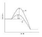
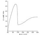
過酸化水素の分解を促進する触媒としては、ほとんどの遷移金属と、二酸化マンガンと、銀と、カタラーゼ酵素とが挙げられる。シングルステップのコンタクトレンズ消毒システムには極めて一般的なことであるが、プラチナが高分子支持剤構造に対する表面コーティングとして溶液に導入される。触媒は、化学反応のエネルギー経路を変化させることにより機能する。図1は、触媒が存在しない場合の活性化に対応するエネルギー(線10)を、触媒が存在する場合の活性化に対応するエネルギー(線12)と比較したグラフを示す。図示されるように、触媒は、過酸化水素に導入されると、触媒がなければ過酸化水素が安定している環境条件で過酸化水素の分解を開始させるのに必要とされる活性エネルギーを低下させるように作用する。 Catalysts that promote the decomposition of hydrogen peroxide include most transition metals, manganese dioxide, silver, and catalase enzymes. As is very common for single-step contact lens disinfection systems, platinum is introduced into the solution as a surface coating for the polymeric support structure. The catalyst functions by changing the energy pathway of the chemical reaction. FIG. 1 shows a graph comparing the energy corresponding to activation in the absence of a catalyst (line 10) with the energy corresponding to activation in the presence of a catalyst (line 12). As shown, when the catalyst is introduced into the hydrogen peroxide, the active energy required to initiate the decomposition of the hydrogen peroxide in environmental conditions where the hydrogen peroxide is stable without the catalyst. Acts to reduce.
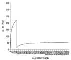
溶液温度、発熱により生じる熱、熱により生じる対流、放出される酸素気泡による力学的撹拌、不均化により生じる希釈、溶液の中の油溶性ガス、及び環境気圧の変化の組合せによって、触媒反応の進行速度が影響されることが分かっている。例えばチバビジョン社により提供されるAO SEPTシステム(システム全体が参照番号13により識別されて図2に示される)のような、コンタクトレンズ用の典型的な市販の過酸化水素消毒カップ・システムによって設けられるようなオープンの環境では、コンタクトレンズは、10ミリリットルの過酸化水素溶液に原則的に触媒と同時に導入され、反応により放出される酸素は、その後、ふた(図2で参照番号15により示される)の中の疎水性膜もしくは一方向弁(図2で参照番号14により示される)を介して排出される。図3に示されるように、この種のシステムでは、酵素反応の結果の溶液濃度が、どちらかというと迅速に約0.1%まで低下した後、溶液槽の濃度が利用者に対して眼球刺激のリスクなしに消毒済みのレンズを眼球に装着して安全なレベルにまで低下するまでに7〜8時間を要する。 The combination of solution temperature, heat generated by heat generation, convection generated by heat, mechanical stirring by released oxygen bubbles, dilution caused by disproportionation, oil-soluble gas in the solution, and changes in ambient pressure, It has been found that the speed of travel is affected. Provided by a typical commercially available hydrogen peroxide disinfection cup system for contact lenses, such as the AO SEPT system offered by Ciba Vision (the entire system is identified by
コンタクトレンズの消毒は、汚れたレンズに発見されることが知られている環境に遍在する多様な生命体を除去するために装着者により定期的に行われる。問題とされる生命体としては、ブドウ球菌、シュードモナス、大腸菌、アカントアメーバ等の多様な病原性株が挙げられるが、これらに限定されない。アカントアメーバは、アカントアメーバ角膜炎と呼ばれる失明に至らしめる可能性のある角膜の感染症に関連する日和見病原体である。一般集団のうち、コンタクトレンズの装着者は、最もこの生命体のリスクにさらされていると云われており、報告された眼感染症のケースのうち95%超を占めている。特に潜行性の高い生命体であるアカントアメーバは、飢餓、乾燥、並びにペーハー及び温度の変化等の条件に晒されると、活性のある栄養体から、休眠してより耐性のある被嚢した段階に移行することができる。被嚢した場合のこの生命体の殺生物剤への抵抗力は、代謝の休眠の結果としてよりも、その嚢胞壁による物的障壁によるところが大きい。嚢胞壁の主成分は耐酸性のたんぱく質及びセルロースであり、外壁、つまり嚢胞外膜は主にたんぱく質から構成され、内側の嚢胞内膜は30%超のセルロースから構成される。被嚢したアカントアメーバは、塩素を含有する消毒剤や塩酸に対してさえも著しい耐性を示すにも拘わらず、過酸化水素に晒すことによって破壊される。 Contact lens disinfection is regularly performed by the wearer to remove a variety of organisms ubiquitous in the environment known to be found on dirty lenses. Examples of organisms that are problematic include, but are not limited to, various pathogenic strains such as staphylococci, Pseudomonas, Escherichia coli, and Acanthamoeba. Acanthamoeba is an opportunistic pathogen associated with a corneal infection that can lead to blindness called Acanthamoeba keratitis. Of the general population, contact lens wearers are said to be most at risk for this organism, accounting for over 95% of reported cases of eye infections. Acanthamoeba, a particularly insidious organism, is exposed to conditions such as starvation, desiccation, and changes in pH and temperature, from an active nutrient to a more resistant encapsulated stage. Can be migrated. When encapsulated, this organism's resistance to biocides is more due to the physical barrier of the cyst wall than as a result of metabolic dormancy. The main components of the cyst wall are acid-resistant protein and cellulose. The outer wall, that is, the outer cystic membrane is mainly composed of protein, and the inner cystic inner membrane is composed of more than 30% cellulose. The encapsulated Acanthamoeba is destroyed by exposure to hydrogen peroxide, despite its extreme resistance to chlorine-containing disinfectants and even hydrochloric acid.
標準の環境条件では、過酸化水素によって病原体が破壊されるのは、酸化によって生命体のたんぱく質が変性されることによる。重度に汚れたレンズ又はアカントアメーバのような耐性細菌を処理する一つの選択肢は、より高濃度の溶液から始めることであるが、この方法には望ましくないユーザ・リスクがある。これらのリスクのいくつかについては、既に記載した。 Under normal environmental conditions, the pathogen is destroyed by hydrogen peroxide because the proteins in the organism are denatured by oxidation. One option to treat resistant bacteria such as heavily soiled lenses or Acanthamoeba is to start with a higher concentration solution, but this method has an undesirable user risk. Some of these risks have already been described.
より魅力的な選択肢は、分解過程を減速させて、濃度が最終的に眼に快適なレベルにまで低下する前に、より長時間に亘って過酸化水素が高濃度に維持されるようにすることである。このような方法では、汚れが一層ひどいレンズを消毒することが可能であり、一般に是認されている濃度の溶液を使用して耐性細菌をより適切に処理することができる。あいにく、今日の消毒システムは、妥当な6〜8時間の夜間待機時間が過ぎたときに、レンズが炎症を引き起こさないよう消毒されているために必要な反応速度によって制限されている。これは、過酸化物溶液の量と、過酸化物の安全で実際的な開始濃度レベルと、使用時に適度な分解を保証するために必要な触媒(たとえば、プラチナ)の大きさとの間で従来量られてきたバランスによるものである。触媒の大きさに関しては、通常、94平方ミリメートル〜141平方ミリメートルの触媒の表面積が、3.0%〜4.0%の過酸化水素溶液1ミリリットル当たりに割り当てられる。通常より小さい触媒によって分解過程は確かに減速するが、放出されるエネルギーの量と溶液濃度とが低下するに従って触媒の表面積の重要性は実際に高まるので、通常より小さい触媒を使用することによって、レンズ溶液が妥当な時間内にユーザにとって快適なレベルに到達しないということが生じ得る。さらに、付着する気泡を失って沈下して行くに従い接触面積が増大する浮遊触媒を使用することにより分解を減速させる方法(たとえば、米国特許第5,468,448号に開示される)は、信頼できる程度に商業化するのは困難であることが立証されている。 A more attractive option is to slow down the degradation process so that the hydrogen peroxide is maintained at a high concentration for a longer period of time before the concentration eventually falls to a level comfortable to the eye That is. Such a method can disinfect lenses that are more heavily soiled and can better handle resistant bacteria using generally accepted concentrations of solution. Unfortunately, today's disinfection systems are limited by the reaction rate required because the lens is disinfected so that it does not cause inflammation after a reasonable 6-8 hour night waiting period. This is traditionally between the amount of peroxide solution, the safe and practical starting concentration level of peroxide, and the size of catalyst (eg, platinum) required to ensure reasonable decomposition during use. This is due to the balance that has been measured. With respect to catalyst size, a catalyst surface area of 94 square millimeters to 141 square millimeters is usually assigned per milliliter of a 3.0% to 4.0% hydrogen peroxide solution. A smaller catalyst will certainly slow down the cracking process, but since the surface area of the catalyst actually increases as the amount of energy released and the solution concentration decreases, by using a smaller catalyst, It can happen that the lens solution does not reach a comfortable level for the user within a reasonable time. Further, methods of slowing down decomposition by using a floating catalyst that increases contact area as it sinks as it loses attached bubbles (eg, as disclosed in US Pat. No. 5,468,448) are reliable. It has proven difficult to commercialize as much as possible.
本発明の実施形態の目的は、消毒方法の改良を提供することである。
本発明の実施形態の別の目的は、当該方法を実施するべく使用可能な装置を提供することである。An object of embodiments of the present invention is to provide an improvement in disinfection methods.
Another object of an embodiment of the present invention is to provide an apparatus that can be used to perform the method.
手短に説明すると、本発明の特定の実施形態は、たとえばコンタクトレンズを過酸化水素及び触媒を使用して消毒するために利用できる方法を提供する。本方法によると、触媒がコンタクトレンズ・ケース等の反応チャンバの中の過酸化水素に導入され、反応チャンバが密閉されると、排気が起きる前に反応チャンバ内の静水圧が比較的高いレベルに達するようにすることができる。排気の前に反応チャンバ内の静水圧を比較的高いレベルに至らしめることが可能なことによって、相加効果によって強化された過酸化水素による消毒処理が提供される。 Briefly described, certain embodiments of the present invention provide methods that can be utilized, for example, to disinfect contact lenses using hydrogen peroxide and a catalyst. According to this method, when a catalyst is introduced into hydrogen peroxide in a reaction chamber such as a contact lens case, and the reaction chamber is sealed, the hydrostatic pressure in the reaction chamber is brought to a relatively high level before evacuation occurs. Can be reached. The ability to bring the hydrostatic pressure in the reaction chamber to a relatively high level before evacuation provides a disinfection treatment with hydrogen peroxide enhanced by the additive effect.
発明の構造及び操作の構成及び方法、並びに発明のさらなる目的及び利点は、以下の記載を添付の図面に関連付けて参照することにより最良に理解されるであろう。
本明細書に開示される発明は、多くの異なる態様の実施形態を許容することができる。しかし、特定の実施形態を図面に示し、以下に詳細に記載する。本開示は、発明の原理の一例と見なされるべきであり、本明細書に例示され記載される特定の実施形態に発明を限定することは意図されていない。 The invention disclosed herein can allow many different embodiments. However, particular embodiments are shown in the drawings and are described in detail below. This disclosure is to be considered as an example of the principles of the invention and is not intended to limit the invention to the specific embodiments illustrated and described herein.
本明細書に開示される方法は、分解過程のエネルギー及び副生成物から相加効果を得ることにより消毒処理を強化する。過酸化水素溶液が触媒により不均化する際に、有益なエネルギーが、放出される酸素分子の熱及び膨張という形で得られる。 The methods disclosed herein enhance the disinfection process by obtaining additive effects from the energy and by-products of the degradation process. When the hydrogen peroxide solution is disproportionated by the catalyst, valuable energy is obtained in the form of heat and expansion of the released oxygen molecules.
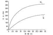
以下により十全に記載されるように、図7及び8は、本発明の実施形態に係る、排気が起きる前に何らかの意義を持つ内圧とすることが可能に構成されたコンタクトレンズ消毒システムを示す。図4は、図7及び8に示すようなシステムを採用した場合の経時内圧変化を示すグラフであり、所定の表面積を有する触媒を使用した場合(図4で参照番号16により識別される曲線により表される)を、当その2倍の表面積を有する触媒を使用した場合(図4で参照番号18により識別される曲線により表される)に比較している。図示されるように、10ミリリットルの溶液からの遊離酸素を、上記の典型的なコンタクトレンズ・カップ(図2に示す)と類似の容積である4ccの上部空間を有する反応チャンバに閉じ込めることによって、948平方ミリメートルの表面積を有する触媒を導入して30分以内に約186p.s.i.の圧力が生成され、その2倍の表面積を有する触媒を導入して30分後に366p.s.i.もの圧力が生成される可能性がある。図4から分かるように、どちらの触媒も9分以内に内圧を100p.s.i.まで上昇させることができ、その時点では、図6に線24で示す過酸化物濃度は、排気されたシステム(線22)においてより4倍超高い。 As described more fully below, FIGS. 7 and 8 illustrate a contact lens disinfection system configured to allow any meaningful internal pressure before exhaust occurs, according to embodiments of the present invention. . FIG. 4 is a graph showing a change in internal pressure over time when the system as shown in FIGS. 7 and 8 is adopted, and when a catalyst having a predetermined surface area is used (by a curve identified by
溶液1立方センチメートル当たりの表面積が94〜141平方ミリメートルを超える触媒は、排気されたシステムでは消毒を有効なものとするには過度に迅速に過酸化水素溶液の濃度を下げてしまうが、そのような触媒を閉じたシステムに導入すると、その他では得られないより良い消毒の可能性が得られることが分かっている。具体的には、触媒が大きいほど、初期の活性率が高くなり、それによりシステム内でより迅速に高静水圧へと圧力上昇が生じる。触媒が大きいほど、液量に対する表面積の比が増大し、したがってより大きな触媒が提供され、終了反応濃度を眼に安全なレベルにまで低下させるのにより効果的となる。 A catalyst with a surface area greater than 94-141 square millimeters per cubic centimeter of solution will reduce the concentration of the hydrogen peroxide solution too quickly to make disinfection effective in an exhausted system. It has been found that introducing the catalyst into a closed system offers better disinfection possibilities than otherwise possible. Specifically, the larger the catalyst, the higher the initial activity rate, thereby causing a pressure increase to higher hydrostatic pressure more quickly in the system. The larger the catalyst, the greater the ratio of surface area to liquid volume, thus providing a larger catalyst and being more effective in reducing the final reaction concentration to an eye-safe level.
放出される酸素を閉じ込めることにより生じる高静水圧によって、溶液に吸収できる溶存酸素の量も増加し、溶液をガスによって飽和させることが可能になる。たとえば、300p.s.i.及び摂氏23度では、約0.0122ミリリットルの酸素が10ミリリットルの溶液槽に溶解する。図5は、触媒が存在しない場合の活性化に対応するエネルギー(線10)を触媒が存在する場合の活性化に対応するエネルギー(線12)に比較しているだけでなく、上昇した圧力での活性化に対応するエネルギー(線20)のプロットもするグラフである。 The high hydrostatic pressure generated by confining the released oxygen also increases the amount of dissolved oxygen that can be absorbed into the solution, allowing the solution to be saturated with gas. For example, 300 p. s. i. And at 23 degrees Celsius, about 0.0122 milliliters of oxygen is dissolved in a 10 milliliter solution bath. FIG. 5 not only compares the energy corresponding to the activation in the absence of the catalyst (line 10) to the energy corresponding to the activation in the presence of the catalyst (line 12), but also at an increased pressure. Is a graph that also plots the energy (line 20) corresponding to the activation of.
初めに、高静水圧の場合、分解に要する活性化エネルギーのレベルが引き上げられることにより反応が減速するが、溶液から上昇するのでなく溶液に溶解する酸素による関与もある。厳密に力学的観点から見ると、拡散によって時間が経つにつれ溶液の濃度は最終的に容器内で均衡するにも拘わらず、過酸化水素は、触媒構造によって分解を開始したとき、溶液槽内で短期間、成層化することが分かっており、圧力下でも溶液に進入して行こうとしない酸素分子がずっと小さい気泡を形成するので、気泡が表面に上昇するときに溶液槽が力学的に混合される程度が減少することとなる。 First, in the case of high hydrostatic pressure, the reaction is slowed by raising the level of activation energy required for decomposition, but it is also involved by oxygen dissolved in the solution rather than rising from the solution. Strictly from a mechanical point of view, hydrogen peroxide does not dissolve in the solution tank when it begins to decompose by the catalyst structure, even though the concentration of the solution eventually balances in the vessel over time due to diffusion. It has been found to stratify for a short period of time, and oxygen molecules that do not attempt to enter the solution even under pressure will form much smaller bubbles, so the solution tank will mix dynamically as the bubbles rise to the surface. Will be reduced.
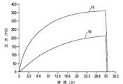
したがって、消毒処理を強化する相加効果は、不均化反応により生じたエネルギー及び副生成物が利用され、処理に再取り込みされて得られる。消毒チャンバ内で酸素を膨張させることにより高められた静水圧によって、より多くの放出酸素が溶液に溶解することが可能となる。その結果、気泡がどんどん小さく少なくなって混合が減少し、分解に対する活性化エネルギー要求が高まる。これにより分解が起こる速度が遅くなり、より長時間にわたって顕著に高い溶液濃度が維持される。図6は、排気されたシステム(つまり、通常の大気条件下にある)(線22)における過酸化物濃度の経時変化を、高圧システム(つまり、通常の大気条件下にある)(線24)における変化と比較している。図示されるように、高い圧力では、過酸化物濃度は、反応に入って5分(つまり、反応時間が5分経過した後)の時点で排気システムの2.4倍であり、10分の時点で排気システムの4.7倍であり、20分の時点で排気システムの6.8倍であり、30分の時点で排気システムの6.4倍である。 Therefore, the additive effect that enhances the disinfection process is obtained by utilizing the energy and by-products generated by the disproportionation reaction and re-incorporating into the process. The increased hydrostatic pressure by expanding oxygen in the disinfection chamber allows more released oxygen to dissolve in the solution. As a result, bubbles become smaller and smaller, mixing is reduced, and the activation energy requirement for decomposition is increased. This slows down the rate at which decomposition occurs and maintains a significantly higher solution concentration over a longer period of time. FIG. 6 shows the change in peroxide concentration over time in an evacuated system (ie under normal atmospheric conditions) (line 22) and the high pressure system (ie under normal atmospheric conditions) (line 24). Compared to changes in As shown, at high pressure, the peroxide concentration is 2.4 times that of the exhaust system at 5 minutes after entering the reaction (ie, after 5 minutes of reaction time) and 10 minutes. It is 4.7 times the exhaust system at the time point, 6.8 times the exhaust system at the 20 minute time point, and 6.4 times the exhaust system at the 30 minute time point.
過酸化水素溶液の潜在的浸透・酸化力を高めるために、密閉され膨張した放出酸素による高圧を利用すると、それにより生成された高静水圧条件によって、病原体の自然な力学的均衡状態を引き出すことが可能である。なぜなら、圧力を受ける溶液槽によって維持される酸素飽和条件下にある生命体の内部の酸素条件が拡散によって高められるためである。その後、さらなる相加効果は、高圧条件がその後急速に減圧する結果、気体の沸騰として観察される溶液からの溶存酸素の放出が生じ、病原体内に過剰に吸収された酸素が膨張して、過酸化水素へ晒されることで酸化による変性を生じていた生命体の細胞膜にさらなるストレスが加えられることにより実現することが可能である。この作用によって、病原体のたんぱく質に対する酸化変性による破壊効果が補われる。減圧後は高圧が緩和されているので、所望の6〜8時間のスパン内に分解が許容レベルまで終了しているようにするべく、触媒反応がより高速な低圧のペースで再開することが可能となる。 To increase the potential penetration and oxidative power of hydrogen peroxide solution, the high pressure generated by the enclosed and expanded oxygen can be used to bring out the natural mechanical equilibrium of the pathogen due to the high hydrostatic pressure condition generated by it. Is possible. This is because the oxygen conditions inside the organism under oxygen saturation conditions maintained by the solution bath under pressure are enhanced by diffusion. Thereafter, a further additive effect is that high pressure conditions then rapidly depressurize, resulting in the release of dissolved oxygen from the solution, which is observed as gas boiling, and the excess absorbed oxygen in the pathogen expands, This can be realized by applying additional stress to the cell membrane of a living organism that has been denatured by oxidation due to exposure to hydrogen oxide. This action compensates for the destructive effect of oxidative denaturation of pathogen proteins. After depressurization, the high pressure is relaxed, so the catalysis can be resumed at a faster, lower pressure pace to ensure that the decomposition has reached an acceptable level within the desired 6-8 hour span. It becomes.
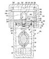
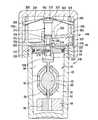
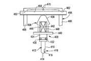
図7及び8は、本発明の実施形態に係る、上記した相加効果により消毒を強化するべく、コンタクトレンズ保持・反応チャンバ内で所望の高圧、酸素飽和状態、及び持続酸化物濃度条件を生成するよう構成されたコンタクトレンズ消毒システム40を示す。 7 and 8 generate the desired high pressure, oxygen saturation, and sustained oxide concentration conditions in the contact lens holding and reaction chamber to enhance disinfection due to the additive effects described above, according to embodiments of the present invention. 1 shows a contact
図7及び8に示すように、コンタクトレンズ消毒システム40は、カップ42と、カップ42の上部46に螺合するよう構成された蓋アセンブリ44とを備える。カップ42は、略円柱状であり、コンタクトレンズを消毒するための反応チャンバ48を内部に設けている点において従来通りである。 As shown in FIGS. 7 and 8, the contact
蓋アセンブリ44は、バルブ本体50と、バルブ本体50に装着され、密着しているステム(stem)52とを備える。適切な時間内に反応を終了するように決められた大きさの触媒54(組成に関して従来通りである)が、ステム52の底部56に付加されている。さらに、コンタクトレンズ保持バスケット58がステム52に配置されている。保持バスケット58は、コンタクトレンズを受け取り、ステム52と保持バスケット58との間に設けられた空間60にコンタクトレンズを維持するために旋回して開閉するよう構成されている。ステム52及び保持バスケット58は、たとえば、本明細書に全体を参照として取り込む米国特許第4,200,187号もしくは米国特許第4,750,610号に記載されたもの等の従来のものであってよい。ステム52には、カップ42の内壁64に対して密閉されるように密閉部材62が設けられている。 The
上記したように、蓋アセンブリ44は、バルブ本体50を備える。バルブ本体50は、好ましくは、図7及び8に示すような単体の多層体から構成され、カップ42の上部46に螺合するよう構成されている。バルブ本体50には、通路66が設けられており、開口68が通路66に通じており、バルブ本体50には、通路66の端部72において通気性膜70が設けられている。通気性膜70は、たとえば、細孔径が好ましくは半ミクロンであるが2ミクロンを上回らないフィルター材もしくは疎水性ろ過材から構成されてよい。 As described above, the
バルブ本体50は、内部にプランジャ76が配置された容器74も備える。プランジャ76は多くの形態をとり得るが、プランジャ76の一つの好ましい構造においては、プランジャ76は、塑性体から構成されており、エラストマー材料から形成されて塑性体の端部に成形されたピストン78を有する。したがって、ピストン78により、プランジャ76の端部80が効果的に規定される。プランジャ76は、ピストン78がピストン・シリンダ領域82を往復(traverse)できるように、バルブ本体59の容器74内を往復(traverse)するよう構成されている。 The
ピストン78は、第1のプランジャ・シール84と第2のプランジャ・シール86とを設けるように構成されている。プランジャ76が図7に示す位置にあるとき、第1及び第2のプランジャ・シール84、86はバルブ本体50の内壁88及び90にそれぞれ密着し、システム40が密閉される。しかし、以下により詳細に記載するように、プランジャ76が図8に示す位置に移動すると、第1のプランジャ・シール84がバルブ本体50の(ピストン・シリンダ領域82における)内壁88との接触状態から摺り出て、反応チャンバ48の排気が可能となる。 The
使用時には、約10ミリリットルの過酸化水素溶液92をカップ42に注入し、ステム52の保持バスケット58を旋回して開き、コンタクトレンズをステム52に載せ、保持バスケット58を旋回して閉め、コンタクトレンズを空間60に保持する。最後に、ステム52をカップ42に挿入し、蓋アセンブリ44をカップ42の上部46に螺合させる。カップ42のサイズは、蓋アセンブリ44がカップ42の上部46に螺合されたとき、カップ42に10ミリリットルの過酸化水素92が収容された状態で、過酸化水素92の上に4ccの上部空間98が残り、消毒処理の際に放出される酸素ガスを閉じ込めることができるように決められていることが好ましい。4ccの上部空間を設けることは一つの可能性であるが、上記したように反応を制御するための所望の内圧を達成するべく、触媒54の表面積を変更することが可能であるのと同じく上部空間98の容積も変更することができる。 In use, about 10 milliliters of
過酸化水素溶液92に触媒54が導入されるのと同時に、ステム52と保持バスケット58との間の空間60に収容されたコンタクトレンズが過酸化水素溶液92に浸漬されると、触媒により刺激される不均化反応が開始する。その後、システム内の消毒液及び圧力は、図7に示すように、密閉部材62がカップ42の内壁64に対して密着し、第1のプランジャ・シール84が壁88に対して密着することにより、カップ42と蓋アセンブリ44との間に収まる。 When the contact lens accommodated in the
バルブ本体50には戻り止めボール100が含められており、バネ部材102によりプランジャ76と接触するよう付勢されている。具体的には、プランジャ76が図7に示すように密着位置にあるとき、戻り止めボール100は、プランジャ76に設けられた受け止め溝104に嵌る。図7に示すような開始位置から、容器74内のプランジャ76の縦運動はプランジャ76の受け止め溝104に存在する戻り止めボール100により制御される。プランジャ76が容器74内を図7に示す位置から図8に示す位置へと移動(traverse)するよう戻り止めボール100を押しのけるのに十分な力がピストン78に対して(図7の矢印106の方向に)働くようになるまで動きが適切に拘束されるよう構成されたバネ要素部材102によって、戻り止めボール100はプランジャ76に保持されている。図7及び8にはボール型の戻り止めが示されているが、細長い形状の戻り止め等、ボールとは異なる形状の戻り止めを使用して類似の機能を達成することができる。とにかく、戻り止め100は、反応チャンバ46が十分な高圧条件に達したときにプランジャ76が図7に示すその密着位置から図8に示すその排気位置へと移動できるように機能する。プランジャ76が図7に示す位置にあるとき、プランジャ・シール84によって放出ガスが効果的に閉じ込められ、プランジャ76に沿って上方に進むことが防がれる。反応チャンバ46内の圧力が十分なレベルに上昇したら、プランジャ76は、図8に示すように容器74内を上方に移動し、反応チャンバ46の排気が可能になる。 The
蓋アセンブリ44は、バルブ本体50を備えているのに加え、バルブ本体50に係合する蓋108を備える。蓋108は、略円柱状であり、たとえば、円周状縁110を介してバルブ本体50を保持する。具体的には、蓋108は、蓋108がバルブ本体50に対して回転可能となるようバルブ本体50に取り付けられている。これは、以下により十分に記載する。とにかく、蓋108は内部に柱112を有し、容器74の中でのプランジャ76の縦運動は、図8に示すように、柱112に接触するプランジャ76の上部114により制限されている。 In addition to including the
ピストン78がピストン・シリンダ領域82内を十分に移動すると、ピストン78は移行部116に進入する。移行部116は、ピストン・シリンダ領域82の内壁88に対するプランジャ・シール84の密着を徐々に減らすように構成されており、したがって上部空間98内からの酸素ガスの漏出と上部空間98への溶存酸素の沸騰とを開始させ、ピストン78を経て移行部116へ、開口68を通って通路66へ、通気性膜70を介して大気へと導く。 When the
上記したように、通気性膜70は、細孔径が好ましくは半ミクロンであるが2ミクロンを上回らないフィルター材もしくは疎水性ろ過材から構成されてよい。過酸化物の反応にとっては本質的なことではないが、通気性膜70は、過酸化物溶液92が触媒により分解された後、望ましくない生命体の侵入に対する障壁となる。 As described above, the air-
減圧によって消毒処理においてさらなる相加効果が得られるのは、上部空間98を占める酸素がピストン78の移動によって漏出可能となり、過酸化水素消毒溶液内の飽和酸素が溶液から沸騰することによって、病原体が力学的均衡を保つために適応できるよりもずっと迅速に上部空間98の圧力が環境大気圧を僅かに上回る点まで低下したときである。大気への排気を含む処理の加圧段階と減圧段階においては、上部空間98の内部の圧力は、図9に示すような上昇・下降を示す(使用される触媒54の大きさに依存する。図4に関連して上述したように、参照番号16により識別される曲線は、所定の表面積を有する触媒を使用した場合に関し、参照番号18により識別される曲線は、その2倍の表面積を有する触媒を使用した場合に関する)。システム40内で高圧が緩和された後、触媒による過酸化水素溶液92の不均化の速度は、活性化エネルギーのレベルが低下しているので、圧力が緩和されるより前の速度より早くなる。溶液92から酸素が沸騰するにつれ混合流も生成され、これらの流れは、初め、成層化を阻止してより多くの過酸化物分子を触媒54に接触させることによって、触媒による分解を加速させる。溶液92が最終的な分解を起こし、中で消毒されているレンズを使用しても眼に安全なレベルにまで過酸化物濃度を低下させている際にも、酸素は継続的に放出される。 A further additive effect is obtained in the disinfection process by the reduced pressure because the oxygen occupying the
上記したように、蓋108は、蓋108がバルブ本体50に対して回転可能となるようにバルブ本体50に取り付けられている。図7及び8に示すように、バルブ本体50の上面120によって、蓋108の内側に設けられた対応する城壁状構造物(castellated structure)124とかみ合うよう構成された城壁状構造物(castellated structure)122が設けられることが好ましい。蓋アセンブリ44の内部の蓋108とバルブ本体50との間に、バネ要素126が設けられていることが好ましい。具体的には、バネ要素126の一端部128が、バルブ本体50に設けられた肩130に係合することが好ましく、バネ要素126の他端部132が蓋108の内面134に係合することが好ましい。したがって、蓋108の内側に設けられた城壁状構造物124は、(バネ要素126によって)付勢され、バルブ本体50の上面120に設けられた対応する城壁状構造物122との係合から外れるようになっている。 As described above, the
消毒処理が終了すると、例えば6〜8時間後に、通常はバルブ本体50に対して回転自在な蓋108を下方に押し下げて、バネ要素126を圧縮させ、蓋108の内面134の城壁状構造物124をバルブ本体50の城壁状構造物122と係合させなければならない。2つの城壁状構造物122、124が互いに係合するように蓋108が押し下げられたあと、反時計方向に蓋108を回転させることで、蓋アセンブリ44は、カップ42の上部46との螺合状態から外れる。 When the disinfection process is completed, for example, after 6 to 8 hours, the
蓋108を下方に押し下げて蓋アセンブリ44を外すことによって、蓋108の柱112もプランジャ76上に押し下がり、プランジャ76が容器74内を下方にシフトして、戻り止めボール100がプランジャ76の受け止め溝104に再び係合する。プランジャ76が下方に移動すると、ピストン・シール84もピストン・シリンダ領域82の内壁88と再び密着する。したがって、その後装置40は、次の消毒処理に向けて用意が整う。 By pushing down the
蓋アセンブリ44を最終的にカップ42から外す前に、残圧があれば解放されるようにするべく、ステム52の密閉部材62がカップ42の上部46に設けられた面取り部140を通ることができるように、カップ42及び蓋アセンブリ44には、それぞれ十分なネジ山136、138が設けられていることが好ましい。反対に、蓋アセンブリ44を取り付ける際には、消毒時に発生する圧力を閉じ込めるために構造が十分に係合されるようにすべく、ステム52の密閉部材62が面取り部140の下に進むまでに十分にネジ締めが行われるようになっている。 Before the
次の消毒サイクルを開始するためにユーザによって行われるように、蓋108がバルブ本体50の上に押し下げられ、かみ合う城壁状構造物122、124が再係合され、蓋アセンブリ44がカップ42に取り付けられると、次のサイクルが始まる前に確実にプランジャ76が適正位置に復帰する。蓋アセンブリ44をカップ42にネジ締めし、蓋108から手を離すと、システムは、図7に示す状態となり、次の消毒サイクルに準備された状態となる。 The
記載したように、図7及び8に示すコンタクトレンズ消毒システム40は、相加効果により消毒処理を強化するよう構成されている。もちろん、上記の相加効果により強化される消毒処理を実施するためのその他の実施形態(たとえば、その他の蓋アセンブリ設計を採用した実施形態)も完全に可能である。 As described, the contact
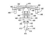
たとえば、図10及び11は、本発明の別の実施形態に係るコンタクトレンズ消毒システム40aの断面図である。図7及び8に示すコンタクトレンズ消毒システム40と同様に、図10及び11に示すコンタクトレンズ消毒システム40aは、上記の相加効果により消毒を強化するために、コンタクトレンズ保持・反応チャンバ内で所望の高圧、酸素飽和状態、及び持続酸化物濃度条件を生成するよう構成されている。 For example, FIGS. 10 and 11 are cross-sectional views of a contact
図10及び11に示すコンタクトレンズ消毒システム40aの構造及び動作は、多くの点で図7及び8に示すコンタクトレンズ消毒システム40に似ている。したがって、同一の部材を識別するのに同一の参照番号を使用する。たとえば、図7及び8に示すコンタクトレンズ消毒システム40によく似て、図10及び11に示すコンタクトレンズ消毒システム40aは、カップ42と、カップ42の上部46に螺合するよう構成された蓋アセンブリ44aとを備え、カップ42は、略円柱状であり、コンタクトレンズを消毒するために内部に反応チャンバ48を備える点において従来通りである。 The structure and operation of the contact
蓋アセンブリ44aは、バルブ本体50aに取り付けられた蓋108aを備える。バルブ本体50aは、カップ42の上部46に螺合するように構成されており、バルブ本体50aにはステム52aが取り付けられて密着している。適切な時間内に反応を終了するように大きさを決められた触媒54(組成に関して従来通りである)が、ステム52aの底部56に取り付けられている。さらに、コンタクトレンズ保持バスケット58がステム52aに配置されている。保持バスケット58は、コンタクトレンズを受け取り、ステム52aと保持バスケット58との間に設けられた空間60にコンタクトレンズを維持するために旋回して開閉するよう構成されている。ステム52aには、カップ42の内壁64に対して密閉されるように密閉部材62が設けられている。 The
上記したように、図7及び8に示すコンタクトレンズ消毒システム40は、バルブ本体50に通路66が設けられ、通路66に開口68が通じて、排気のための流路が設けられるようになっている。対照的に、図10及び11に示すコンタクトレンズ消毒システム40aは、ステム52aの上部202とバルブ本体50aとの間に流路200が設けられている。 As described above, in the contact
蓋アセンブリ44aはプランジャ204を備え、プランジャ204の底部206によってピストン208が形成されている。ピストン208は、半球形の端面210を有する略円柱状であってよい。ピストン208は、排気特性212を備えており、それは、たとえばピストン208に沿った縦溝(slot)214である。図10及び11では縦溝214が示されているが、たとえば、ピスト208の側部に沿った平坦部(flat)や、ピストン208に沿って径が減少する区間(section)等、その他の形態を排気特性212は取ってもよい。とにかく、以下により十分に記載するよう、排気特性212は、反応チャンバ48を排気するために流路200と連通する。 The
ステム52aとバルブ本体50aとの間の受け取り溝218にはピストン・シール216が設けられており、プランジャ204の円柱状部224の受け取り溝222にはプランジャ・シール220が設けられている。両シール216及び220は、適切なエラストマー材料から形成されていることが好ましい。プランジャ204は、さらに半球状の上部226とフランジ228とを備えていることが好ましい。以下により十分に記載するが、プランジャ204は、バルブ本体50aに対して上下に往復(traverse)してカップ42の中の反応チャンバ48の排気及び密閉をそれぞれ促すように構成されている。 A
蓋アセンブリ44aは、バルブ本体50aと蓋108aとの間においてバルブ本体50aの内側の上面232に取り付けられたバネ保持部材230をさらに備える。バネ保持部材230は、単体の多層体であることが好ましい。バネ保持部材230は、図11に示すように、プランジャ204のフランジ228と接触することによりプランジャ止めとして機能する内側方向延伸フランジ234を備えることが好ましい。バネ保持部材230は、制御バネ238を受け取る開口236と、制御バネ支持体240とをさらに備える。図12に示すように、制御バネ238は、略U型の断面を有するビーム状部材(beam−like member)であることが好ましく、圧力誘起された荷重を当接するプランジャ204から制御バネ支持体240に伝達してプランジャ204の上方移動に抵抗するビーム(beam)として作用する。図12では特定の制御バネ構成が示されているが、制御バネはその他の形態を取ってよい。とにかく、バネ保持部材230によってその開口236に制御バネ238は保持され、制御バネ238は、効果的にプランジャ204の上下移動を制御するよう作用する。具体的には、プランジャ204の円柱状部224がバルブ本体50aのプランジャ・シリンダ領域242を往復(traverse)する際、ピストン208がバルブ本体50aのピストン・シリンダ領域244を往復(traverse)する。初め、コンタクトレンズ消毒システム40aは図10に示すような状態にあり、プランジャ204は下方位置にある。下方位置では、プランジャ204のフランジ228がバルブ本体50aの面245に接触しており、プランジャ204がさらに下方に移動できないようになっている。 The
図7及び8に示すコンタクトレンズ消毒システム40とよく似て、図10及び11に示すコンタクトレンズ消毒システム40aでは、使用時に、約10ミリリットルの過酸化水素溶液92をカップ42に注入し、ステム52aの保持バスケット58を旋回して開き、コンタクトレンズをステム52aに載せ、保持バスケット58を旋回して閉め、コンタクトレンズを空間60に保持する。最後に、ステム52aをカップ42に挿入し、蓋アセンブリ44aをカップ42の上部46に螺合させる。カップ42のサイズは、蓋アセンブリ44がカップ42の上部46に螺合されたとき、カップ42に10ミリリットルの過酸化水素92が収容された状態で、過酸化水素92の上に4ccの上部空間98が残り、消毒処理の際に放出される酸素ガスを閉じ込めることができるように決められていることが好ましい。4ccの上部空間を設けることは一つの可能性であるが、上記したように反応を制御するための所望の内圧を達成するべく、触媒54の表面積を変更することが可能であるのと同じく上部空間98の容積も変更することができる。 Much like the contact
触媒54を過酸化水素溶液92に導入し、蓋アセンブリ44aをカップ42の上部46に螺合させてコンタクトレンズ消毒システム40aを密閉すると、システム40aは図10に示すような状態となり、反応チャンバ48の圧力は上昇し始める。進行中の不均化によってピストン208に対する上部空間98の圧力が上昇し続け、それに反応してプランジャ204が(上方に)移動する(traverse)するにつれ、制御バネ238の「U」型が変形して、「U」型の断面高さが減少し、制御バネ238のビーム強度(beam strength)が減少する。プランジャ204から制御バネ238に伝わる力の結合(combination)が制御バネ238の最大ビーム強度に達したとき、制御バネ238は扁平・座屈し、プランジャ204(及びピストン208)は、図11に示すようにプランジャ204のフランジ228がプランジャ止め234に当接するまで、上方に移動できるようになっている。この変形した状態では、制御バネ238がプランジャ204に及ぼす抵抗力は、著しく小さくなっている。屈曲力に対して制御バネ238が及ぼす典型的な抵抗力は、図13を参照することでより明確に理解することができる。図13は、制御バネ238等のバネのビーム強度が撓み(deflection)量によって変化する様子を示すグラフである。図13に示すように、制御バネ238は、自身を圧迫するプランジャ204が0.090インチの移動距離に達したときに2.69単位の最大ビーム強度を示し、プランジャが0.105インチの移動距離に達したとき(つまり、ちょうど.025インチ後)に0.64単位(もしくは、最大値の25%未満)の最小ビーム強度を示す。 When the
プランジャ204がプランジャ止め234に向かって上方に移動することによって、ピストン208の排気特性212がピストン・シール216を越えることが可能となり、上部空間98の中の圧力を受けた酸素が漏出する通路が形成される。排気特性212に沿って流れる漏出酸素は、ピストン・シール216の上に進んで流路200に流入し、カップ42の周縁246とバルブ本体50aとの間と、カップ42と蓋アセンブリ44aとにそれぞれ設けられたネジ山136及び138の一致する面どうしの間の、ぴったりとした、しかし密閉されていない界面に沿ってゆっくり漏出する。これらの密閉されていない界面によって気体が大気へと流れることが可能になり、流速は抑制されるものの、漏出ガスに圧力的制約はかからない。ピストン208の排気特性212に沿って移動するガス圧は、ピストン208とバルブ本体50aとの間の空隙に沿っても通過するので、プランジャ・シール220に衝突する。プランジャ・シール220は直径が大きいので、プランジャ止め234及び制御バネ238に対してプランジャ204が加える力は、ピストン208が発揮する力を上回り、上部空間98内のゆっくり放散して行くガス圧が十分に低下して、制御バネ238がプランジャ204の力に勝ってプランジャ204を下方に押し下げ、図10に示すようにピストン208の排気特性212がピストン・シール216の下に下がって上部空間98と大気との連通が遮断されるまで、ピストン208が発揮する力より大きいままでいる。 Movement of the
図13に示すように機能するバネ(つまり、制御バネ238)と0.0123平方インチの面積のピストン208による受け止め力(receiving force)とを利用する実施例を適用することによって、図11に示すように排気を生じる程度に制御バネ238が十分に撓む前に、図14に示すように上部空間98内で219p.s.i.のピーク圧力が達成できるようになる。ピストン208の2倍の直径を有するプランジャ・シール220は、0.049平方インチの表面積を有し、上部空間98の残圧が約13p.s.i.にまで低下するまでは制御バネ238を撓んだままにしておくに足る力を発揮する。残圧が約13p.s.i.になると、制御バネ238が真っすぐになり、プランジャ204(及びピストン208)は下方に押し戻され、図10に示すように面245に再び着地(reseat)する。 By applying an embodiment utilizing a spring that functions as shown in FIG. 13 (ie, control spring 238) and a receiving force by
上記のように上部空間98が排気された後、圧力によって抑制されていた触媒反応の活性は増大し、その後、過酸化水素が水と酸素とに変換されることで過酸化物の供給が逓減的に(at a decreasing rate)消尽していくにしたがい低下する。プランジャ204及びピストン208が(図10に示すように)再び着地(reseat)した後の残圧が、残っている過酸化水素の分解によって生じる圧力と結合することにより、消毒処理が開始してから6〜8時間で終了に向かうにつれ、上部空間98の圧力は図14に示すように上昇する。 After the
図7及び8に示すコンタクトレンズ消毒システム40とよく似て、図10及び11に示すコンタクトレンズ消毒システム40aは、蓋アセンブリ44aを最終的にカップ42から外す前に、残圧があれば解放されるようにするべく、ステム52aの密閉部材62がカップ42の上部46に設けられた面取り部140を通ることができるように、カップ42及び蓋アセンブリ44aには、それぞれ十分なネジ山136、138が設けられていることが好ましい。反対に、蓋アセンブリ44aを取り付ける際には、消毒時に発生する圧力を閉じ込めるために構造が十分に係合されるようにすべく、ステム52aの密閉部材62が面取り部140の下に進むまでに十分にネジ締めが行われるようになっている。 Much like the contact
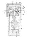
図15及び16は、本発明のさらに別の実施形態に係るコンタクトレンズ消毒システム40bの断面図である。システム40bも、上記の相加効果により消毒を強化するために、コンタクトレンズ保持・反応チャンバ内で所望の高圧、酸素飽和状態、及び持続酸化物濃度条件を生成するよう構成されている。図15及び16に示すコンタクトレンズ消毒システム40bの構造及び動作は、多くの点で上記のコンタクトレンズ消毒システム40、40aに似ている。したがって、同一の部材を識別するのに同一の参照番号を使用する。たとえば、コンタクトレンズ消毒システム40、40aによく似て、コンタクトレンズ消毒システム40bは、カップ42と、カップ42の上部46に螺合するよう構成された蓋アセンブリ44bとを備え、カップ42は、略円柱状であり、コンタクトレンズを消毒するために内部に反応チャンバ48を備える点において従来通りである。 15 and 16 are cross-sectional views of a contact
蓋アセンブリ44bは、バルブ本体50bに取り付けられた蓋108bを備える。バルブ本体50bは、単体の多層体であることが好ましく、カップ42の上部46に螺合するように構成されている。バルブ本体50bにはステム52が取り付けられて密着している。適切な時間内に反応を終了するように大きさを決められた触媒54(組成に関して従来通りである)が、ステム52の底部56に取り付けられている。さらに、コンタクトレンズ保持バスケット58がステム52に配置されている。保持バスケット58は、コンタクトレンズを受け取り、ステム52と保持バスケット58との間に設けられた空間60にコンタクトレンズを維持するために旋回して開閉するよう構成されている。ステム52には、カップ42の内壁64に対して密閉されるように密閉部材62が設けられている。 The
コンタクトレンズ消毒システム40によく似て、コンタクトレンズ消毒システム40bは、バルブ本体50bに通路300が設けられ、通路300に開口302が通じて、反応チャンバ48を排気するための流路が設けられるようになっている。通路300の端部には栓303があり、栓303は、流路の端部を密閉し、かつ、酸化物溶液92が触媒により分解された後、望ましくない生命体の侵入に対する障壁となる。バルブ本体50bは、さらに開口304、つまり排出口を有しており、排気ガスが通路300からカップ42の周縁246に流れ、カップ42と蓋アセンブリ44bとの間のネジ山136、138に沿って大気へと出て行くことが可能となる。栓303は、通路300に圧力を閉じ込めて、排気ガスが排出口304を通り、ネジ山136、138に沿って漏出するのを制限する働きをする。 Similar to the contact
バルブ本体50bには、バネ支持体308に隣接した制御バネ238(当該制御バネは、図10及び11に示すシステム40aの制御バネと実質的に同一であることが好ましい)を保持するための開口306が設けられている。バルブ本体50bはプランジャ容器310を備えており、プランジャ容器310にはプランジャ312が配置される。プランジャ312は多くの形態を取ることが可能であるが、プランジャ312の一つの好ましい構成では、プランジャ312は、塑性体から構成されており、エラストマー材料から形成されて塑性体に成形され、プランジャ・シール324とピストン・シール326とを提供するピストン314を有する。 The
プランジャ312は、半球状の上面318とフランジ320とを有することが好ましい。図15に示すように、プランジャ312は、バルブ本体50bの容器310の内部を往復(traverse)するよう構成され、フランジ320は、容器310の内部でのプランジャ312の下方移動を、フランジ320とバルブ本体50bの面322との接触によって制限するよう構成されている。 The
プランジャ312は、プランジャ・シール324を形成しており、ピストン・シール326は、ピストン314に設けられている。プランジャ312が容器310内を往復(traverse)するとき、プランジャ・シール324は容器310のプランジャ・シリンダ領域328を往復(traverse)し、ピストン・シール326は容器310のピストン・シリンダ領域330を往復(traverse)する。プランジャ・シリンダ領域328とピストン・シリンダ領域330との間には移行領域332が設けられており、プランジャ312は、ピストン・シール326とプランジャ・シール324との間に位置するプランジャ・ステム334を有する。プランジャ312の端部316には、プランジャ・ガイド336があり、プランジャ・ガイド336は、ピストン・シリンダ領域330においてバルブ本体50bの内壁338と接触し、ピストン314を位置調整するよう構成されている。
コンタクトレンズ消毒システム40、40aとよく似て、図15及び16に示すコンタクトレンズ消毒システム40bでは、使用時、約10ミリリットルの過酸化水素溶液92をカップ42に注入し、ステム52の保持バスケット58を旋回して開き、コンタクトレンズをステム52に載せ、保持バスケット58を旋回して閉じて、コンタクトレンズを空間60に保持する。最後に、ステム52をカップ42に挿入して、蓋アセンブリ44bをカップ42の上部46に螺合させる。カップ42のサイズは、蓋アセンブリ44がカップ42の上部46に螺合されたとき、カップ42に10ミリリットルの過酸化水素92が収容された状態で、過酸化水素92の上に4ccの上部空間98が残り、消毒処理の際に放出される酸素ガスを閉じ込めることができるように決められていることが好ましい。4ccの上部空間を設けることは一つの可能性であるが、上記したように反応を制御するための所望の内圧を達成するべく、触媒54の表面積を変更することが可能であるのと同じく上部空間98の容積も変更することができる。 Similar to the contact
触媒54を過酸化水素溶液92に導入し、蓋アセンブリ44bをカップ42の上部46に螺合させてコンタクトレンズ消毒システム40bを密閉すると、システム40bは図15に示すような状態となり、反応チャンバ48の圧力は上昇し始める。図15に示す開始位置から、バルブ本体50b内を移動(traversing)するプランジャ312の縦運動は制御バネ238により制限される。制御バネ238は、上部空間98内の圧力がピストン・シリンダ領域330に入り、制御バネ238のビーム強度(beam strength)を上回る十分な力でピストン314を圧迫し、それにより制御バネ238が扁平・座屈し始めるまで、プランジャの移動を拘束するよう構成されている。制御バネ238がこの変形を生じたとき、ピストン314はピストン・シリンダ領域330を出て移行領域332に移動(traverse)している。プランジャ・ステムの先端334は、ピストン・シリンダ領域330のバルブ本体50bの内壁338と係合したままになっており、プランジャ312を安定させている。 When the
上部空間98からの加圧酸素流が移行領域332を経てプランジャ・シリンダ領域328に流入し、次に、より大きい直径を有するプランジャ・シール324を圧迫して制御バネ328にさらなる力を加え、蓋108の下面に設けられたストッパ凸部(stop boss)342(図16参照)に制御バネ328を押しつけることを可能にするべく、プランジャ・ステムの先端334には、1つ以上の平坦部(flats)340(もしくはその他の構造)を設けることが好ましい。プランジャ・シール324は、自身が受けるガス圧に反応して上昇するとき、開口302を開通させるので、圧力を受けたガスが通路300に進入して、カップ42の周縁246の真上に位置する排出口304に通ずることが可能になる。 Pressurized oxygen flow from the
排出口304を出たガスは、カップ42の周縁246及びバルブ本体50bの密閉されていないが隣接している面に当たり、当該面に沿って流れ、カップ42の周縁246周りに分散され、その後、ネジ山136及び138の一致面に沿って大気へと流れる。漏出ガスが行き当たるこれらの密閉されていない面によっては、流速は抑制されるものの、漏出ガスに圧力的制約はかからない。反応チャンバ48の圧力が十分に低下すると、排気の結果、図15に示すように、制御バネ238によってプランジャ312は押し下げられ、システム40bがリセットされる。 The gas exiting the
コンタクトレンズ消毒システム40、40aによく似て、図15及び16に示すコンタクトレンズ消毒システム40bは、蓋アセンブリ44bを最終的にカップ42から外す前に、残圧があれば解放されるようにするべく、ステム52の密閉部材62がカップ42の上部46に設けられた面取り部140を通ることができるように、カップ42及び蓋アセンブリ44bには、それぞれ十分なネジ山136、138が設けられていることが好ましい。反対に、蓋アセンブリ44bを取り付ける際には、消毒時に発生する圧力を閉じ込めるために構造が十分に係合されるようにすべく、ステム52の密閉部材62が面取り部140の下に進むまでに十分にネジ締めが行われるようになっている。 Much like the contact
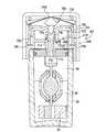
図17及び18は、本発明のさらに別の実施形態に係るコンタクトレンズ消毒システム40cの断面図である。システム40cも、上記の相加効果により消毒を強化するために、コンタクトレンズ保持・反応チャンバ内で所望の高圧、酸素飽和状態、及び持続酸化物濃度条件を生成するよう構成されている。図17及び18に示すコンタクトレンズ消毒システム40cの構造及び動作は、多くの点で上記のコンタクトレンズ消毒システム40、40a、40bに似ている。したがって、同一の部材を識別するのに同一の参照番号を使用する。たとえば、コンタクトレンズ消毒システム40、40a、40bによく似て、コンタクトレンズ消毒システム40cは、カップ42と、カップ42の上部46に螺合するよう構成された蓋アセンブリ44cとを備え、カップ42は、略円柱状であり、コンタクトレンズを消毒するために内部に反応チャンバ48を備える点において従来通りである。 17 and 18 are cross-sectional views of a contact
蓋アセンブリ44cは、バルブ本体50cに取り付けられた蓋400を備える。蓋400は、蓋400の内面404に配置された柱402を有し、蓋400をバルブ本体50cに保持された状態に保つ円周状縁406を有する。 The
バルブ本体50cは、単体の多層体であることが好ましく、カップ42の上部46に螺合するよう構成されている。バルブ本体50cには、ステム52が装着され、密着している。適切な時間内に反応を終了するように決められた大きさの触媒54(組成に関して従来通りである)が、ステム52の底部56に付加されている。さらに、コンタクトレンズ保持バスケット58がステム52に配置されている。保持バスケット58は、コンタクトレンズを受け取り、ステム52と保持バスケット58との間に設けられた空間60にコンタクトレンズを維持するために旋回して開閉するよう構成されている。ステム52には、カップ42の内壁64に対して密閉されるように密閉部材62が設けられている。 The
上記のコンタクトレンズ消毒システム40、40a、40bとよく似て、図17及び18に示すコンタクトレンズ消毒システム40cでは、使用時に、約10ミリリットルの過酸化水素溶液92をカップ42に注入し、ステム52の保持バスケット58を旋回して開き、コンタクトレンズをステム52に載せ、保持バスケット58を旋回して閉め、コンタクトレンズを空間60に保持する。最後に、ステム52をカップ42に挿入し、蓋アセンブリ44cをカップ42の上部46に螺合させる。カップ42のサイズは、蓋アセンブリ44がカップ42の上部46に螺合されたとき、カップ42に10ミリリットルの過酸化水素92が収容された状態で、過酸化水素92の上に4ccの上部空間98が残り、消毒処理の際に放出される酸素ガスを閉じ込めることができるように決められていることが好ましい。4ccの上部空間を設けることは一つの可能性であるが、上記したように反応を制御するための所望の内圧を達成するべく、触媒54の表面積を変更することが可能であるのと同じく上部空間98の容積も変更することができる。 In a similar manner to the contact
蓋アセンブリ44cはプランジャ408を備え、プランジャ408の底部410は、ピストン412を形成する。ピストン412は、半球状の端面414を有する略円柱状であってよい。ピストン412は、排気特性416を備えており、それは、たとえばピストン412に沿った縦溝418である。図17〜20では縦溝418が示されているが、たとえば、ピスト412の側部に沿った平坦部(flat)や、ピストン412に沿って径が減少する区間(section)等、その他の形態を排気特性416は取ってもよい。とにかく、以下により十分に記載するよう、排気特性416は、蓋400とバルブ本体50cとの間の開口424に沿って反応チャンバ48を排気するために、バルブ本体50cの排気口420と、最終的に流路422とに連通する。 The
ステム52とバルブ本体50cとの間の受け取り溝428には、ピストン・シール426が設けられており、プランジャ408の円柱状部434の受け取り溝432には、プランジャ・シール430が設けられている。両シール426、430は、適切なエラストマー材料から形成されていることが好ましい。プランジャ408上にはプランジャ蓋436が配置されていることが好ましく、プランジャ蓋436によって半球状の上部438が設けられ、プランジャ408によってフランジ440が設けられる。プランジャ408は、プランジャ蓋436内の容器446に受け取られる上方延伸柱442も備えており、プランジャ蓋バネ448が容器446内に配置されている。以下により十分に記載するが、プランジャ408は、バルブ本体50cに対して上下に往復(traverse)してカップ42の中の反応チャンバ48の排気及び密閉をそれぞれ促すように構成されている。 A
図17及び18に示すように、バルブ本体50cの上面450によって、蓋400の内側に設けられた対応する城壁状構造物(castellated structure)454とかみ合うよう構成された城壁状構造物(castellated structure)452が設けられることが好ましい。バネ保持部材456が、バルブ本体50cと蓋400との間の、バルブ本体50cの内側上面458に取り付けられている。バネ保持部材456は、単体の多層体であることが好ましい。バネ保持部材456は、図18に示すように、プランジャ408のフランジ440と接触することによってプランジャ止めとして機能する内側方向延伸ストッパ460を備えていることが好ましい。図19及び20に示すように、バネ保持部材456は、以下により詳細に記載するが、制御バネ464、制御バネ支持体466、及び蓋伸縮バネ構造470(cap return spring structures)を受け止める開口462も備えている。バネ保持部材456は、広がって分離することによりプランジャ蓋436を通すよう構成された可撓性ラッチ部材(deflectable latching members)468も備える(図18参照)。 As shown in FIGS. 17 and 18, the
制御バネ464は、コンタクトレンズ消毒システム40及び40b(図10〜16及び関連する上記の記載を参照)に含まれる制御バネ238とよく似たものであることが好ましい。したがって、制御バネ464は、略U型の断面を有するビーム状部材(beam−like member)であることが好ましく、圧力誘起された荷重を当接するプランジャ408から制御バネ支持体466に伝達してプランジャ408の上方移動に抵抗するビーム(beam)として作用する。バネ保持部材456は、制御バネ464を自身の開口462(図19及び20参照)に保持し、制御バネ464は、プランジャ408の上下移動を効果的に制御するよう作用する。具体的には、プランジャ408の円柱状部434がバルブ本体50cのプランジャ・シリンダ領域472を往復(traverse)するとき、ピストン412は、バルブ本体50cのピストン・シリンダ領域474を往復(traverse)する。初め、コンタクトレンズ消毒システム40cは、図17に示すような状態にあり、プランジャ408は下方位置にある。下方位置では、プランジャ408のフランジ440がバルブ本体50cの面476に接触しており、プランジャ408がさらに下方に移動できないようになっている。 The
上記したように、制御バネ464は、圧力誘起された荷重を当接するプランジャ408から制御バネ支持体466に伝達する(図17及び19参照)ことにより、プランジャ408(及びプランジャ蓋436)の上方移動に抵抗するビームとして作用する。進行中の不均化によってピストン412に対する上部空間98内の圧力が望ましい180p.s.i.から366p.s.i.に上昇するにつれ、プランジャ408(プランジャ蓋436と共に)は、制御バネ464に打ち勝つに足る力を得る。それに反応して、制御バネ464の「U」型は変形し始め、「U」型の断面高さが減少して、制御バネ464のビーム強度(beam strength)が低下する。プランジャ408によって伝達される力が制御バネ464の最大ビーム強度に達すると、バネ464は、その断面が減少するにともない扁平・座屈し、プランジャ408(ピストン412及びプランジャ蓋436と共に)が、図18及び20に示すように、上方に移動できるようになるが、フランジ440がバルブ本体50cに取り付けられたプランジャ止め460に当接すると、プランジャ408のさらなる上方移動は阻まれる。この変形した状態では、制御バネ464がプランジャ408に及ぼす抵抗力は、著しく小さくなっている。図19及び20に示す制御バネ464等のバネが曲げ荷重に反応して示す典型的な形状の変遷、及びそのような形状変遷の際のバネの抵抗力は、図13を参照することでより明確に理解することができる。図17〜20に示す制御バネ464は、自身を圧迫するプランジャ408が0.090インチの移動距離に達したときに2.69単位の最大ビーム強度を示し、プランジャがちょうど0.025インチ後の0.105インチの移動距離に達したときに0.64単位もしくは、最大値の25%未満の最小ビーム強度を示す。ピストン412の移動によって、プランジャ408が上方に、フランジ440がプランジャ止め460に向けて押しやられることで、図18に示すように排気特性416の先端がピストン・シール426を越えることが可能になり、上部空間98内の加圧酸素が漏出する通路が形成され、消毒システム40c内が減圧され始める(図21)。具体的には、上部空間98を出てプランジャ・シリンダ領域472に進入する加圧酸素ガスは、プランジャ・シール30により塞がれ、その後、排気口420に流され、そこから流路422(及び開口424)を通って大気へと方向付けられる。 As described above, the
プランジャ408の上方移動と同時に、フランジ440がストッパ460に近づくにつれ、上方へと押しやられているプランジャ蓋436によって可撓性ラッチ部材468が広がって分離し、プランジャ蓋436が通り抜けることが可能になる。その後、ラッチ部材468が元の位置に戻ると、プランジャ蓋436は、図18に示すように上方に捕捉された状態となり、それにより制御バネ464が撓んだ状態に保持される(図18及び20に示すように)。その後、プランジャ蓋バネ448によって、プランジャ408に下方に向かう力のみが加えられる。プランジャ蓋バネ448からの小さな力は、本例においては0.12lb〜0.50lbの範囲であるが、上部空間98内の圧力がたとえば9.8p.s.i.〜40p.s.i.の範囲にまで放散していれば、プランジャ408(ピストン412と共に)を下方に押し戻すには十分である。ピストン412の下方移動によって、排気特性416の先端がピストン・シール426の下にまで進むことが可能になり、図17に示すように、上部空間98と大気との連通が遮断される。上記のように上部空間98が排気された後、圧力によって抑制されていた触媒反応の活性は、初めは増大し、その後過酸化水素が水と酸素とに変換されることで過酸化物の供給が逓減的に(at a decreasing rate)消尽していくにしたがい減少する。上部空間98内の圧力が触媒反応の活性化に反応して上昇し始めるにつれ、ピストン412に圧力がかかることで、排気特性416がピストン・シール426を越えるのに十分な移動が可能になって上部空間98から圧力が漏出可能になるのに十分な程度に、プランジャ408によってプランジャ蓋バネ448が圧縮される。上部空間98内の圧力が再び排気されると、プランジャ408を圧迫するバネ464の力によって、プランジャ408(及びピストン412)がピストン・シール426に沿って下方に押され、排気特性416を介した流れが遮断される。この低圧によって引き起こされる開閉の排気サイクルは継続し、上部空間98内の圧力は低く維持され、6〜8時間の反応時間が終了して眼に安全な過酸化物濃度レベルが到達されるまでカップ42内で過酸化水素が不均化して酸素ガスが遊離し続ける間、上部空間98と大気との連通が外側への流れに制限される。 Simultaneously with the upward movement of the
たとえば6〜8時間後に消毒処理が終了すると、消毒済みのコンタクトレンズを取り出すべく、縁406によってバルブ本体50cに保持された回転自在な蓋400を押し下げ、蓋400の城壁状構造物452をバルブ本体50cの対応する城壁状構造物454に噛み合わせ、蓋アセンブリ44cがカップ42の上部46との螺合から外れるようにしなければならない。蓋400を押し下げる動作によって、制御バネ支持体466から延伸する蓋伸縮バネ構造470も蓋400の内部の柱402によって制御バネ464に抵抗して下方に撓み、プランジャ蓋436がラッチ部材468に押し付けられる。この動作により、プランジャ蓋436に対する下方圧力に反応してラッチ部材468が外側に撓み、ラッチ部材468の中をプランジャ蓋436が通ることが可能になり、さらに、図17に示すように、プランジャ408が元の着地した(seated)位置に押しやられる。すると、プランジャ蓋436は、定位置に復元して今では頭上にあるラッチ部材468に再び捕捉される。したがって、蓋アセンブリ44cをカップの上部46から取り外して交換するのに必要な押し下げ動作によって、内部に収容された圧力制御メカニズムは次の消毒サイクルに向けて準備された状態にリセットされる。上記のその他のシステム40、40a、40bによく似て、蓋アセンブリ44cを最終的にカップ42から外す前に、残圧があれば解放されるようにするべく、ステム52の密閉部材62がカップ42の上部46に設けられた面取り部140を通ることができるように、カップ42及び蓋アセンブリ44cには、それぞれ十分なネジ山478、480が設けられていることが好ましい。反対に、蓋アセンブリ44cを取り付ける際には、消毒時に発生する圧力を閉じ込めるために構造が十分に係合されるようにすべく、ステム52の密閉部材62が面取り部140の下に進むまでに十分にネジ締めが行われるようになっている。 For example, when the disinfection process is completed after 6 to 8 hours, the
図21は、図17及び18に示す消毒システム40cを採用した場合の、カップ42内の圧力の経時変化を示すグラフである(使用される触媒54の大きさに依存する。参照番号16により識別される曲線は、所定の表面積を有する触媒を使用した場合に関し、参照番号18により識別される曲線は、その2倍の表面積を有する触媒を使用した場合に関する)。図21に示すように、システム40cは、大気への排気を含む処理の加圧段階と減圧段階においては、上部空間98の内部の圧力は、初め上昇し(つまり、制御バネ464により確立される高圧レベルにまで)、その後、排気の最中に急激に低下する。排気の後、圧力は僅かに増減する(つまり、プランジャ408とプランジャ蓋バネ448との相互作用によりもたらされる低圧制御に反応して)。初期の高圧が緩和されるのと同時に、カップ42内部での過酸化水素溶液92の触媒による不均化の速度は、活性化エネルギーのレベルが低下しているので、圧力が緩和されるより前の速度より早くなる。溶液92から酸素が沸騰するにつれ混合流も生成され、これらの流れは、初め、成層化を阻止してより多くの過酸化物分子を触媒54に接触させることによって、触媒による分解を加速させる。溶液が最終的な分解を起こし、中で消毒されているレンズを使用しても眼に安全なレベルにまで過酸化物濃度を低下させている際にも、酸素は継続的に上部空間98に放出され、上記した周期的な排気によって制御されている。 FIG. 21 is a graph showing the change over time of the pressure in the
図22及び23は、本発明のさらに別の実施形態に係るコンタクトレンズ消毒システム40dの断面図である。システム40dも、上記の相加効果により消毒を強化するために、コンタクトレンズ保持・反応チャンバ内で所望の高圧、酸素飽和状態、及び持続酸化物濃度条件を生成するよう構成されている。図22及び23に示すコンタクトレンズ消毒システム40dの構造及び動作は、多くの点で上記のコンタクトレンズ消毒システム40、40a、40b、40cに似ている。したがって、同一の部材を識別するのに同一の参照番号を使用する。たとえば、コンタクトレンズ消毒システム40、40a、40b、40cによく似て、コンタクトレンズ消毒システム40dは、カップ42と、カップ42の上部46に螺合するよう構成された蓋アセンブリ44dとを備え、カップ42は、略円柱状であり、コンタクトレンズを消毒するために内部に反応チャンバ48を備える点において従来通りである。 22 and 23 are cross-sectional views of a contact
蓋アセンブリ44dは、バルブ本体50dに取り付けられた蓋108dを備える。バルブ本体50dは、単体の多層体であることが好ましく、カップ42の上部46に螺合するように構成されている。バルブ本体50dにはステム52が取り付けられて密着している。適切な時間内に反応を終了するように大きさを決められた触媒54(組成に関して従来通りである)が、ステム52の底部56に取り付けられている。さらに、コンタクトレンズ保持バスケット58がステム52に配置されている。保持バスケット58は、コンタクトレンズを受け取り、ステム52と保持バスケット58との間に設けられた空間60にコンタクトレンズを維持するために旋回して開閉するよう構成されている。ステム52には、カップ42の内壁64に対して密閉されるように密閉部材62が設けられている。 The
バルブ本体50dには、バネ支持体508に隣接した制御バネ538(当該制御バネ538は、図10及び11に示され、上記されたシステム40aの制御バネ238と実質的に同一であることが好ましい)を保持するための開口506が設けられている。以下により十分に記載するように、プランジャ512が、バルブ本体50dに対して上下に往復(traverse)するように構成されており、制御バネ538は、バルブ本体50dに対するプランジャ512の上方移動を制限・制御するよう作用する。 The
バルブ本体50dは、プランジャ容器510を備えており、プランジャ512は、プランジャ容器510に配置されている。プランジャ512は、略円柱状部519から上方に延在する半球状の上面518を有していることが好ましく、略円柱状部519からはステム部521が下方に延伸している。プランジャ512は多くの形態をとり得るが、プランジャ512の一つの好ましい構成では、プランジャ512は、塑性体から構成されており、エラストマー材料から形成されて塑性体に成形されたピストン514を有し、プランジャ・シール524及びピストン・シール526が設けられている。プランジャ・シール524は、プランジャ512の略円柱状部519に設けられており、ピストン・シール526は、下方に延伸するステム部521に設けられている。ピストン・シール526は、バルブ本体50dのピストン・シリンダ領域530の内壁538内で動作し、当該内壁に密着するが、プランジャ・シール524は、バルブ本体50dのプランジャ・シリンダ領域528の内壁539内で動作し、当該内壁に密着する。プランジャ・シリンダ領域528とピストン・シリンダ領域530との間には移行領域532が設けられている。 The
上記したように、プランジャ512は、バルブ本体50dの容器510の内部を上下に往復(traverse)摺るように構成され、制御バネ538は、バルブ本体50dに対するプランジャ512の上方移動を制限・制御するように作用する。プランジャ512の下方移動に関しては、プランジャ512の略円柱状部519の底面533が、図22に示すようにバルブ本体50bの内壁535と接触することによって、容器510の中でのプランジャ512の下方移動を制限するよう構成されている。 As described above, the
プランジャ512の端部516には、プランジャ・ガイド536があり、プランジャ・ガイド536は、ピストン・シリンダ領域530においてバルブ本体50dの内壁538と接触し、ピストン514を位置調整するよう構成されている。加圧酸素が上部空間98から移行領域532を経てプランジャ・シリンダ領域528に流入し、次に、より大きい直径を有するプランジャ・シール524を圧迫して制御バネ538にさらなる力が加わり、制御バネ538が蓋108dの下面に設けられたストッパ凸部(stop boss)542(図23参照)に押しつけられるようにするべく、1つ以上の平坦部(flats)540、及び/又は排気切り欠き541、及び/又はその他の構造をプランジャ・ガイド536に設けることが好ましい。 At the
コンタクトレンズ消毒システム40dは、バルブ本体50dに取り付けられたフラッパ弁572、柱574、及び栓576から構成された圧力調整バルブ570を備える。ピストン・シール526が自身が受けるガス圧に反応して上昇するにつれピストン・シリンダ領域530の内壁538との密着状態から摺り出て移行領域532に進入することによって、上部空間98内のガスが圧力調整バルブ570を通って栓576に設けられた排気口578から排気されることが可能になる。具体的には、排気ガスは、バルブ本体50dの開口579を通って進み、排出口578に沿い、蓋108dとバルブ本体50dとの間に設けられた空間560に出る。コンタクトレンズ・ケースの排気を促すために、圧力調整バルブ570と類似した排気弁が従来採用されてきた(米国特許第4,956,156号参照)。 The contact
図22に示す下方の開始位置から、バルブ本体50dの内部を往復する(traversing)プランジャ512の縦運動は、内圧が所定の点に達するまでプランジャの移動を拘束するよう構成された制御バネ538によって制限される。内圧(つまり上部空間98内の)が十分に高くなると、プランジャ512は上方に移動し、ガスがプランジャ・ガイド536を越えて流れ(つまり、平坦部540、排気切り欠き541、及び/又はその他の構造を介して)、ピストン514の略円柱状部519を圧迫することとなる。それにより、プランジャ512の上面518が制御バネ538を圧迫することによって、プランジャ512により荷重が制御バネ538に伝達される。制御バネ238と同じく、制御バネ538は断面が「U」型をしており、圧力誘起された荷重を当接する上面518から制御バネ支持体508に伝達し、プランジャ512の上方移動に抵抗するビームとして作用する。 The longitudinal movement of the
ピストン512に対する上部空間98内の圧力(進行中の溶液92の不均化による)が望ましい180p.s.i.から上記の366p.s.i.の高圧条件に上昇するにつれ、プランジャ512(上面518と共に)は、制御バネ538に打ち勝つに足る力を得る。それに反応して、制御バネ538の「U」型は変形し始め、「U」型の断面高さが減少し、制御バネ538のビーム強度(beam strength)が低下する。プランジャ512によって制御バネ538に伝達される力が制御バネ538の最大ビーム強度に達すると、バネ538は、その断面が減少するにしたがって扁平・座屈し、図23に示すように、バネ538が蓋108dのストッパ542に当接するまでプランジャ512(ピストン514及び上面518と共に)が上方に移動できるようになる。この変形した状態では、制御バネ538がプランジャ514に及ぼす抵抗力は、著しく小さくなっている。制御バネ538等のバネが曲げ荷重に反応して示す典型的な形状の変遷は、図22での制御バネ538の形状を図23に示すその形状と比較することでより明確に理解することができ、そのような形状変遷の際のバネの抵抗力は、図13を参照することでより明確に理解することができる。図13に示すように、図22及び23に示す制御バネ538等のバネは、自身を圧迫するプランジャ512が0.090インチの移動距離に達したときに2.69単位の最大ビーム強度を示し、プランジャがちょうど0.025インチ後の0.105インチの移動距離に達したときに0.64単位もしくは、最大値の25%未満の最小ビーム強度を示す。 The pressure in the
制御バネ538の変形によってピストン514がピストン・シリンダ領域530を出て移行領域532に進入し始めると、減圧が始まり、ピストン514を圧迫する加圧酸素が移行領域532に入ることが可能になる。ガス流を通り抜けさせる1つ以上の排気平坦部(vent flats)540、及び/又は排気切り欠き541、及び/又はその他の構造を有するプランジャ・ガイド536は、ピストン・シリンダ領域530の内壁538と係合したままになり、制御バネ538に向けて上方に移動(traverse)するプランジャ512を安定させる。ピストン512を越えて流れる加圧酸素ガスは、移行領域532を通過し、プランジャ・シリンダ領域528に入り、次にプランジャ512の略円柱状部519及びプランジャ・シール524を圧迫して、制御バネ538にさらなる力を加え、制御バネ538が蓋108dのストッパ542に押し付けられる。たとえば、ピストン514の直径が0.125インチであれば、220p.s.i.の上部空間圧力に反応してプランジャ512によって制御バネ538に伝達される力は2.7lbsであろう。さらなる例として、プランジャ・シリンダ領域528の直径が0.357インチであり、同じ220p.s.i.の圧力を受けるガスがプランジャ・シール524の下に進入すれば、制御バネ538に直に加わる潜在的力は、22ポンドに増大するであろう。しかし、一方向低圧感圧式の圧力調整バルブ570が設けられているので、増大した力は、瞬間的なものでしかない。 When the
プランジャ・シリンダ領域528に進入し、プランジャ・シール524によって閉じ込められたガスは、圧力調整バルブ570によってのみ大気に漏出できる。栓576によって柱574に保持されたフラッパ弁572は、バルブ本体50dに設けられた開口579を介してプランジャ・シリンダ領域528と通ずる。たとえば20p.s.i.〜32p.s.i.の閾値圧力に達すると、フラッパ弁572に向かう加圧酸素ガスがフラッパ572と柱574との環状接点で排気され、排出口578及び空間560を通って大気に出ることが可能になることで、上部空間98の減圧が促される。フラッパ572に対する圧力が元の閾値圧力の下のレベル(本例では、閾値圧力より約3p.s.i.〜8p.s.i.低い)まで低下した後、フラッパ572が柱574に再び密着し、排気は止む。本例では、プランジャ512を圧迫する12p.s.i.の再密着圧力(resealing pressure)によって、制御バネ538に対して1.2ポンドの力が加えられる。図23から理解できるように、この力は、制御バネ538をバネ止め542に対して堅固に保持するのに十分であり、制御バネ538は、0.11インチの撓みを維持するのに0.66ポンドの力しか要さず、0.15インチの撓みを維持するのに0.81ポンドの力しか要さない。最初の排気の後、上部空間98内の圧力は、圧力調整バルブの排気圧力とその再密着圧力との間で変動するが、過酸化水素92の分解が完了に向けて継続しているので、通常、再密着圧力を下回ることはない。制御バネ538が図13に示すように動作すると想定すると、調整バルブ570の再密着圧力が6.6p.s.i.を下回った場合、もしくはフラッパ572が柱574に再密着し損じた場合、制御バネ538によってプランジャ512が押し下げられ、ピストン514がピストン・シリンダ領域530の内壁538と再係合することにより、上部空間98と溶液92とが大気との連通から遮断され、異物もしくは生命体の侵入のリスクが防止される。通常の使用において、調整バルブ570の不具合がなければ、上部空間98内の酸素ガス圧は、圧力調整バルブの排気圧力とその再密着圧力との間のレベルにとどまり、密閉部材62と面取り部140との間をガスが通過して圧力を緩和させるのに十分なほどに蓋44が外されるまでは、プランジャ512が上方に維持され、制御バネ538が撓んだまま維持される。 Gas that enters the
コンタクトレンズ消毒システム40、40a、40b、40cとよく似て
図22及び23に示すコンタクトレンズ消毒システム40dは、使用時に、約10ミリリットルの過酸化水素溶液92をカップ42に注入し、ステム52の保持バスケット58を旋回して開き、コンタクトレンズをステム52に載せ、保持バスケット58を旋回して閉め、コンタクトレンズを空間60に保持する。最後に、ステム52をカップ42に挿入し、蓋アセンブリ44dをカップ42の上部46に螺合させる。カップ42のサイズは、蓋アセンブリ44dがカップ42の上部46に螺合されたとき、カップ42に10ミリリットルの過酸化水素92が収容された状態で、過酸化水素92の上に4ccの上部空間98が残り、消毒処理の際に放出される酸素ガスを閉じ込めることができるように決められていることが好ましい。4ccの上部空間を設けることは一つの可能性であるが、上記したように反応を制御するための所望の内圧を達成するべく、触媒54の表面積を変更することが可能であるのと同じく上部空間98の容積も変更することができる。The contact
触媒54を過酸化水素溶液92に導入し、蓋アセンブリ44dをカップ42の上部46に螺合させてコンタクトレンズ消毒システム40dを密閉すると、システム40dは、図22に示すような状態になり、反応チャンバ48内の圧力は上昇し始める。図22に示す開始位置から、バルブ本体50d内を往復する(traversing)プランジャ512の縦運動は、制御バネ538によって制限される。制御バネ538は、上部空間98内の圧力がピストン・シリンダ領域530に進入し、制御バネ538のビーム強度を上回るのに十分な力でピストン514を圧迫することによって、制御バネ538が扁平・座屈し始めるまでの間、プランジャの移動を拘束するよう構成されている。制御バネ538のこのような変形が生じたとき、ピストン514は、ピストン・シリンダ領域530を出て移行領域532の中に移動(traverse)している。プランジャ・ガイド536は、ピストン・シリンダ領域530の中のバルブ本体50dの内壁538と係合されたままであり、プランジャ512を安定させている。 When the
コンタクトレンズ消毒システム40、40a、40b、40cとよく似て、図21及び22に示すコンタクトレンズ消毒システム40dは、蓋アセンブリ44dを最終的にカップ42から外す前に、残圧があれば解放されるようにするべく、ステム52の密閉部材62がカップ42の上部46に設けられた面取り部140を通ることができるように、カップ42及び蓋アセンブリ44dには、それぞれ十分なネジ山136、138が設けられていることが好ましい。反対に、蓋アセンブリ44dを取り付ける際には、消毒時に発生する圧力を閉じ込めるために構造が十分に係合されるようにすべく、ステム52の密閉部材62が面取り部140の下に進むまでに十分にネジ締めが行われるようになっている。 Much like the contact
減圧によって消毒処理においてさらなる相加効果が得られるのは、上部空間98を占める酸素がピストン514の移動によって漏出可能となり、過酸化水素消毒溶液内の飽和酸素が沸騰することによって、病原体が力学的均衡を保つために適応できるよりもずっと迅速に上部空間98の圧力が環境大気圧を僅かに上回る点まで低下したときである。大気への排気を含む処理の加圧段階と減圧段階においては、上部空間98の内部の圧力は、初め、制御バネ538により確立される高圧レベルにまで上昇し、その後、排気の最中に急激に低下する。排気の後、圧力は、圧力調整バルブの排気圧力と再密着圧力とに対するプランジャ512の反応によりもたらされる低圧制御に反応して、図24に示すように僅かに増減する。初期の高圧が緩和されるのと同時に、過酸化水素溶液92の触媒による不均化の速度は、活性化エネルギーのレベルが低下しているので、圧力が緩和されるより前の速度より早くなる。溶液92から酸素が沸騰するにつれ混合流も生成され、これらの流れは、初め、成層化を阻止してより多くの過酸化物分子を触媒54に接触させることによって、触媒による分解を加速させる。溶液92が最終的な分解を起こし、中で消毒されているレンズを使用しても眼に安全なレベルにまで過酸化物濃度を低下させている際にも、酸素は継続的に上部空間98に放出され、調整バルブ570の周期的な排気によって制御されている。 A further additive effect can be obtained in the disinfection process by reducing the pressure. Oxygen occupying the
図25及び26は、本発明のさらに別の実施形態に係るコンタクトレンズ消毒システム40eの断面図である。システム40eは、図22及び23に示すシステム40dに非常によく似ており、バルブ本体50eに取り付けられた蓋108eを含む蓋アセンブリ40eを備え、バルブ本体50eには調整バルブ570eがある。システム40eはプランジャ512eを備え、プランジャ512eの下端にはピストン514eが下方延伸ピストン521eとして設けられている。しかし、図22及び23に示すシステム40dとは異なり、システム40eのプランジャ・シール524eは、プランジャ512eの略円柱状部519eの溝602内に保持される密閉部材600として設けられており、ピストン・シール526eは、バルブ本体50eとステム52との間に設けられた受け取り溝606内に保持される密閉部材604として設けられている。両密閉部材600、604は、適切なエラストマー材料から形成されていることが好ましい。以下にさらに記載されるが、プランジャ512eの下方延伸部521eには、上部空間98からのガスの進行を可能にするために縦溝608、平坦部(flat)、径が減少する区間(section)、及び/又はその他の構造が設けられている。 25 and 26 are cross-sectional views of a contact
図22及び23に示すシステム40dとちょうど等しく、図25及び26に示すシステム40eのプランジャ512eは、バルブ本体50eに対して上下に往復(traverse)可能であり、プランジャ512eの上方への縦運動は、U型(断面において)の制御バネ538eによって制御される。図25及び26に示すシステム40eの制御バネ538eは、上記のその他の「U」型制御バネとほぼ同じく構成され、動作する。したがって、図13と、そのようなバネに関する上掲の記載とを適用することができる。 22 and 23 is exactly the same as the
操作時、触媒54を過酸化水素溶液92に導入し、蓋アセンブリ44eをカップ42の上部46に螺合させてコンタクトレンズ消毒システム40eを密閉すると、システム40eは、図25に示すような状態になり、反応チャンバ48内の圧力は上昇し始める。図25に示す開始位置から、バルブ本体50e内を往復する(traversing)プランジャ512eの縦運動は、制御バネ538eによって制限される。制御バネ538eは、上部空間98内の圧力がプランジャ512eを押し上げるのに十分になり、図26に示すように、プランジャ512eが上方に移動し(バネ538eを蓋108eのストッパ542eに到達させるまで)、溝608、平坦部、径が減少する区間、及び/又はその他の構造がピストン・シール526eを越えて摺り上がるまでの間、プランジャの移動を拘束するよう構成されている。その後、上部空間98のガスは、ピストン514eとピストン・シリンダ領域530eの内壁539eとの間に設けられた空間610に沿って移動し、プランジャ・シリンダ領域528eに進入し、プランジャ・シール524eによって止められる。そこでは、プランジャ512eの表面積が追加されることで、上面518eによって制御バネ538eに加えられる力が効果的に増大する。 In operation, when the
システム40dとよく似て、図25及び26に示すシステム40eでは、たとえば、ピストン514eの直径が0.125インチであれば、上部空間98内で220p.s.i.の圧力に達したとき、プランジャ512eの上面518eによって、制御バネ538eに対して2.7lbsの屈曲力が加えられるであろう。比較して、プランジャ512eの直径が0.357インチであれば、220p.s.i.の圧力に晒されたとき、制御バネ538eに対して、22lbsの力を加える可能性がある。しかし、一方向低圧感圧式の圧力調整バルブ570eが設けられているので、増大した力は、瞬間的なものでしかない。 Similar to
プランジャ・シリンダ領域528eに進入し、プランジャ・シール524eにより閉じ込められたガスは、図22及び23に示すシステム40dに関連して上記したように、圧力調整バルブ570eによってのみ大気に漏出することができる。12p.s.iにおいてプランジャ512eによって加えられる力は、バネ538eを撓んだ状態に保ち、上部空間98と調整弁570eとの連通を維持するのに十分である。 Gas that enters the
システム40dに関して上記したように、図25及び26に示すシステム40eでは、圧力は、初め、制御バネ538eにより確立される高圧にまで上昇し、その後、排気の最中に急激に低下する。排気の後、圧力は、調整バルブ570eによりもたらされる低圧制御に反応して、図24に示すように僅かに増減する。最初の排気の後、上部空間98内の圧力は、圧力調整バルブの排気圧力とその再密着圧力との間で変動するが、通常、再密着圧力を下回ることはない。この低圧で増減する圧力のパターンは、減圧後、過酸化水素92の分解が、眼に安全なレベルにまでより低い濃度に向けて継続する間、数時間継続する。 As described above with respect to
制御バネ538eが図13に示すように動作すると想定すると、調整バルブ570eの再密着圧力が6.4p.s.i.を下回った場合、もしくは調整バルブ570eが再密着し損じた場合、制御バネ538eによってプランジャ512eが押し下げられ、図25に示すように、縦溝608、平坦部、径が減少する区間、及び/又はその他の構造がピストン・シール526eの下にまで落ち、効果的に、上部空間98と溶液92とが大気との連通から遮断され、異物もしくは生命体の侵入のリスクが防止される。 Assuming that the
その他のシステム40、40a、40b、40c、40dと同じく、図25及び26に示すシステム40eは、蓋アセンブリ44eを最終的にカップ42から外す前に、残圧があれば解放されるようにするべく、ステム52の密閉部材62がカップ42の上部46に設けられた面取り部140を通ることができるように、カップ42及び蓋アセンブリ44eには、それぞれ十分なネジ山136、138が設けられていることが好ましい。反対に、蓋アセンブリ44eを取り付ける際には、消毒時に発生する圧力を閉じ込めるために構造が十分に係合されるようにすべく、ステム52の密閉部材62が面取り部140の下に進むまでに十分にネジ締めが行われるようになっている。 Like the
その他のシステム40、40a、40b、40c、40dと同じく、図25及び26に示すシステム40eでは、システム40e内の高圧の解放により生じる減圧によって、上記したように変性中の病原体の細胞膜にさらなるストレスを生成することにより、消毒処理にさらに相加効果がもたらされる。 As with the
上記した各システム40、40a、40b、40c、40d、40eでは、システム内の高圧の解放により生じる減圧によって、上部空間98を占める酸素が制御下で漏出することが可能になり、過酸化水素消毒溶液の中の飽和酸素が沸騰することによって病原体が力学的均衡を保つために適応できるよりもずっと迅速に上部空間98内の圧力が制御された低圧レベルに低下したとき、消毒処理にさらなる相加効果がもたらされる。 In each of the
上記したシステム40、40a、40b、40c、40d、40eのいずれも、隔壁(diaphragm)を備えるよう設計し直すことが可能である。図27及び28は、図22及び23、並びに25及び26に示すシステム40d及び40eがこの通りに再設計された例を示す。図27及び28に示すように、システム40fは、隔壁チャンバ701に設置された隔壁700を、バルブ本体50fとバネ保持部材702との間の定位置に保持されたエラストマー材料として備えている。図示するように、バネ保持部材702は、隔壁700を保持されたまま保つ肩703を有する。隔壁700の一部704は、プランジャ708の延伸部706と係合している。プランジャ708は上下に移動可能であり、通常、バルブ本体50fのプランジャ受け止め容器710に出入りする。プランジャ708が第1の位置にあるとき、図27に示すように、プランジャ708の延伸部706はプランジャ受け止め容器710に収容されており、圧力調整バルブ570fを通じたシステム40fの排気は生じない。この位置では、隔壁700はバルブ本体50fの内部肩712に密着しており、上部空間98内の圧力は、溶液92が触媒54と反応している間、上昇することが可能である。しかし、システム40fの圧力が十分に高い圧力にまで上昇すると、上部空間98内の圧力によって、プランジャ708は、図28に示す位置まで押し上げられる。この位置では、隔壁チャンバ701はもはやバルブ本体50fの内部肩712によって上部空間98に密着しておらず、システム40fは、隔壁700とバルブ本体50fとの間に設けられた空間714に沿い、隔壁チャンバ701へ、バルブ本体50fとカップ42の上部との間の界面716に沿って圧力調整バルブ570fを出ることで排気することが可能になる。オーバーモールド成形された面を有するプランジャを効果的に代替するものとして隔壁を使用する違いの他は、システム40fは、両システム40d及び40eと同様に構成され動作する。したがって、システム40fは、たとえば、ストッパ742fを有する蓋108fと、図12に示す制御バネ238と同一であり、その他の実施形態に関連して詳細に上述したU型制御バネ738とを備える。 Any of the
本発明の特定の実施形態を図示して記載したが、当業者であれば、本発明の趣旨及び範囲から逸脱することなく、本発明の多様な変形例を考案し得ることが想定される。 While particular embodiments of the present invention have been illustrated and described, it will be appreciated by those skilled in the art that various modifications of the present invention may be devised without departing from the spirit and scope of the invention.
Claims (87)
Translated fromJapanese内部に前記過酸化水素溶液を保持するよう構成されたカップと、
前記カップと係合可能であり、前記物品及び前記触媒を保持するよう構成された蓋アセンブリと
を備え、
前記蓋アセンブリは、前記消毒システムを密閉するための第1の位置と、前記消毒システムを排気するための第2の位置との間をシフト可能な部材を備え、
前記消毒システムは、前記過酸化水素溶液が前記触媒に反応する結果として反応チャンバ内の圧力が上昇し、その間、相加効果によって前記物品の消毒が強化され、かつ前記シフト可能部材が前記第1の位置にあるように構成され、
前記消毒システムは、前記反応チャンバ内の圧力がさらに上昇することによって、前記シフト可能部材が前記第1の位置から前記第2の位置にシフトし、それにより、前記反応チャンバが排気されるように構成されており、
前記蓋アセンブリは、蓋と、バルブ本体とをさらに備え、
前記蓋は、前記バルブ本体からバネ付勢されて離間されているが、前記バルブ本体に向けて押されることが可能であり、それにより、前記バルブ本体は前記蓋の内面に係合され、その後に前記蓋が回転されることによって、前記蓋アセンブリは前記カップから外れ、
前記蓋は、前記蓋が押し下げられると、前記シフト可能な部材に接触して前記第2の位置から前記第1の位置に移動させる
ことを特徴とする消毒システム。A disinfection system that uses ahydrogen peroxide solution and a catalyst to disinfect articles,
A cup configured to hold thehydrogen peroxide solution therein;
A lid assembly engageable with the cup and configured to hold the article and the catalyst;
The lid assembly comprises a member that is shiftable between a first position for sealing the disinfection system and a second position for exhausting the disinfection system;
The disinfecting system increases the pressure in the reaction chamber as a result of thehydrogen peroxide solution reacting with the catalyst, during which the disinfection of the article is enhanced by an additive effect, and the shiftable member is the first member. Configured to be in the position
The disinfection system may cause the shiftable member to shift from the first position to the second position by further increasing the pressure in the reaction chamber, thereby evacuating the reaction chamber. Configured,
The lid assembly further comprises a lid and a valve body,
The lid is spring biased away from the valve body but can be pushed toward the valve body so that the valve body is engaged with the inner surface of the lid and thereafter When the lid is rotated, the lid assembly is detached from the cup,
The disinfection system, wherein when the lid is pushed down, the lid contacts the shiftable member and moves from the second position to the first position.
ことを特徴とする請求項1に記載の消毒システム。The disinfection system according to claim 1, further comprising a member that is biased to contact the shiftable member to hold the shiftable member in the first position.
前記消毒システムは、前記シフト可能部材が前記第1の位置にあるとき、前記第1のシール及び前記第2のシールが前記バルブ本体と接触しているよう構成され、
前記消毒システムは、前記シフト可能部材が前記第2の位置にあって、前記反応チャンバが排気されている間、前記第2のシールは前記バルブ本体に接触しているが、前記第1のシールは前記バルブ本体と接触していない
ことを特徴とする請求項1に記載の消毒システム。The shiftable member comprises a first seal and a second seal;
The sterilization system is configured such that when the shiftable member is in the first position, the first seal and the second seal are in contact with the valve body;
The disinfection system is configured such that the second seal is in contact with the valve body while the shiftable member is in the second position and the reaction chamber is evacuated. The disinfection system according to claim 1, wherein is not in contact with the valve body.
前記開口は、前記シフト可能部材が前記第1の位置にあるとき、前記シフト可能部材の前記第1及び第2のシールの間に配置される
ことを特徴とする請求項3に記載の消毒システム。The valve body is provided with an opening communicating with the exhaust passage,
The disinfection system of claim 3, wherein the opening is disposed between the first and second seals of the shiftable member when the shiftable member is in the first position. .
ことを特徴とする請求項1に記載の消毒システム。The disinfecting system according to claim 1, wherein the shiftable member is a plunger.
ことを特徴とする請求項5に記載の消毒システム。The disinfection system according to claim 5, further comprising a detent member that is biased to contact the plunger.
前記戻り止め部材は、前記プランジャが前記第1の位置にあるとき、前記戻り止め受け取り機構の中に配置される
ことを特徴とする請求項6に記載の消毒システム。The plunger has its own detent receiving mechanism;
The sterilization system according to claim 6, wherein the detent member is disposed within the detent receiving mechanism when the plunger is in the first position.
ことを特徴とする請求項7に記載の消毒システム。8. The detent member of claim 7, wherein the detent member restrains movement of the shiftable member until sufficient force is applied to the shiftable member as a result of increased pressure in the cup. Disinfection system.
ことを特徴とする請求項6に記載の消毒システム。The sterilization system according to claim 6, wherein the detent member is a detent ball.
前記戻り止め部材は、前記プランジャが前記第1の位置にあるとき、前記戻り止め受け取り機構の中に配置される
ことを特徴とする請求項9に記載の消毒システム。The plunger has its own detent receiving mechanism;
The sterilization system of claim 9, wherein the detent member is disposed within the detent receiving mechanism when the plunger is in the first position.
ことを特徴とする請求項10に記載の消毒システム。11. The detent member restrains movement of the shiftable member until sufficient force is applied to the shiftable member as a result of increased pressure in the cup. Disinfection system.
前記蓋は、前記プランジャに向かって延伸し、前記プランジャと接触することによって前記プランジャの移動を制限する柱を備え、
前記柱を前記プランジャに接触させて前記プランジャを前記第2の位置から前記第1の位置に移動させるべく、前記蓋は押されることが可能である
ことを特徴とする請求項1に記載の消毒システム。The shiftable member is a plunger;
The lid includes a column that extends toward the plunger and limits movement of the plunger by contacting the plunger;
The disinfection of claim 1, wherein the lid can be pushed to move the plunger from the second position to the first position by contacting the column with the plunger. system.
ことを特徴とする請求項1に記載の消毒システム。The disinfection system of claim 1, wherein the lid has an edge configured to hold the lid on the valve body.
前記蓋は、前記バルブ本体からバネ付勢されて離間されているが、前記バルブ本体に向けて押されることが可能であり、それによって、前記バルブ本体の前記城壁状構造物は前記蓋の前記内面の前記城壁状構造物に係合され、その後に前記蓋が回転されることによって、前記蓋アセンブリは前記カップから外れる
ことを特徴とする請求項1に記載の消毒システム。The valve body has a rampart structure, and the inner surface of the lid has a rampart structure,
The lid is spring-biased away from the valve body, but can be pushed toward the valve body so that the wall-like structure of the valve body is The disinfection system according to claim 1, wherein the lid assembly is detached from the cup by engaging the wall-like structure on the inner surface and then rotating the lid.
ことを特徴とする請求項1に記載の消毒システム。The disinfecting system according to claim 1, wherein the shiftable member is a plunger formed from a body having an elastomeric material.
をさらに備える請求項1に記載の消毒システム。The disinfection system according to claim 1, further comprising: a plunger contact element that contacts the valve body; and a filter membrane in an exhaust port that prevents foreign substances and life forms from entering thehydrogen peroxide solution in the cup.
前記過酸化水素溶液を内部に保持するよう構成されたカップと、
前記カップに係合可能で、前記物品及び前記触媒を保持するよう構成された蓋アセンブリと
を備え、
前記蓋アセンブリは、前記消毒システムを密閉するための第1の位置と、前記消毒システムを排気するための第2の位置との間をシフト可能な部材と、前記シフト可能部材が前記第2の位置にあるとき前記シフト可能部材と接触しており、前記シフト可能部材を前記第2の位置から前記第1の位置に付勢するよう構成された制御バネとを備え、
前記消毒システムは、前記過酸化水素溶液が前記触媒に反応する結果として前記消毒システム内の圧力が上昇し、その間、相加効果によって前記物品の消毒が強化され、かつ前記シフト可能部材が前記第1の位置にあるよう構成され、
前記消毒システムは、前記消毒システム内の圧力がさらに上昇することによって、前記シフト可能部材が前記第1の位置から前記第2の位置にシフトし、それによって、前記消毒システムが排気されるよう構成され、
前記消毒システムは、排気の間、前記消毒システム内の圧力が低下し、それによって、前記制御バネが前記シフト可能部材を前記第2の位置から前記第1の位置に押し、それにより、前記消毒システムが再び密閉されるように構成されており、
前記制御バネは、略U型の断面を有するビーム状部材である
ことを特徴とする消毒システム。A disinfection system that uses ahydrogen peroxide solution and a catalyst to disinfect articles,
A cup configured to hold thehydrogen peroxide solution therein;
A lid assembly engageable with the cup and configured to hold the article and the catalyst;
The lid assembly includes a member that is shiftable between a first position for sealing the disinfection system and a second position for exhausting the disinfection system; and the shiftable member is the second position. A control spring configured to contact the shiftable member when in position and bias the shiftable member from the second position to the first position;
The disinfection system increases the pressure in the disinfection system as a result of thehydrogen peroxide solution reacting with the catalyst, during which the disinfection of the article is enhanced by an additive effect, and the shiftable member is Configured to be in position 1,
The sterilization system is configured such that further increase in pressure within the sterilization system causes the shiftable member to shift from the first position to the second position, thereby evacuating the sterilization system. And
The sterilization system reduces the pressure in the sterilization system during evacuation, whereby the control spring pushes the shiftable member from the second position to the first position, thereby the sterilization system. The system is configured to be sealed again,
The disinfection system, wherein the control spring is a beam-like member having a substantially U-shaped cross section.
ことを特徴とする請求項17に記載の消毒システム。The sterilization system of claim 17, wherein the lid assembly further comprises a valve body configured to engage an upper portion of the cup.
ことを特徴とする請求項18に記載の消毒システム。The disinfection system according to claim 18, wherein the lid assembly further includes a spring holding member that holds the control spring and is attached to the valve body.
ことを特徴とする請求項17に記載の消毒システム。The disinfecting system according to claim 17, wherein the shiftable member has an exhaust mechanism.
前記ステムと前記バルブ本体との間には、密着部材が配置され、
前記シフト可能部材は、排気機構を有し、
前記排気機構は、前記シフト可能部材が前記第1の位置から前記第2の位置にシフトするとき、前記密着部材を通ることで、前記システムの排気を可能にする
ことを特徴とする請求項17に記載の消毒システム。The lid assembly further comprises a valve body configured to engage an upper portion of the cup, and a stem engaging the valve body;
A close contact member is disposed between the stem and the valve body,
The shiftable member has an exhaust mechanism;
The exhaust mechanism allows the system to be exhausted by passing through the contact member when the shiftable member shifts from the first position to the second position. Disinfection system as described in.
前記シフト可能部材の前記排気機構は、前記シフト可能部材が前記第1の位置から前記第2の位置にシフトするとき、前記密着部材を通ることで、前記排気路に沿って前記システムの排気を可能にする
ことを特徴とする請求項21に記載の消毒システム。An exhaust path is provided between the stem and the valve body,
The exhaust mechanism of the shiftable member allows the exhaust of the system along the exhaust path by passing through the contact member when the shiftable member shifts from the first position to the second position. The disinfection system according to claim 21, characterized in that it enables.
前記ステムと前記バルブ本体との間には第1の密着部材が設けられ、
前記シフト可能部材は、排気機構を有し、
前記シフト可能部材の前記排気機構は、前記シフト可能部材が前記第1の位置と前記第2の位置との間をシフトするとき、前記密着部材を通り、
前記シフト可能部材には、第2の密着部材が配置されており、前記バルブ本体に密着する
ことを特徴とする請求項17に記載の消毒システム。The lid assembly further comprises a valve body configured to engage an upper portion of the cup, and a stem engaging the valve body;
A first contact member is provided between the stem and the valve body,
The shiftable member has an exhaust mechanism;
The exhaust mechanism of the shiftable member passes through the contact member when the shiftable member shifts between the first position and the second position,
The disinfecting system according to claim 17, wherein a second contact member is disposed on the shiftable member and is in close contact with the valve body.
前記排気機構は、前記シフト可能部材が前記第1の位置から前記第2の位置にシフトするとき、前記第1の密着部材を通ることで、前記排気路に沿って前記システムの排気を可能にする
ことを特徴とする請求項23に記載の消毒システム。An exhaust path is provided between the stem and the valve body,
The exhaust mechanism allows the system to be exhausted along the exhaust path by passing through the first contact member when the shiftable member shifts from the first position to the second position. The disinfection system according to claim 23, wherein:
ことを特徴とする請求項18に記載の消毒システム。The disinfection system according to claim 18, wherein the valve body is configured to contact the shiftable member at the first position to restrict further movement of the shiftable member.
前記前記バネ保持部材は、前記第2の位置において前記シフト可能部材に接触して、前記シフト可能部材のさらなる移動を規制するよう構成されている
ことを特徴とする請求項19に記載の消毒システム。The valve body is configured to contact the shiftable member at the first position to regulate further movement of the shiftable member;
20. The disinfection system according to claim 19, wherein the spring retaining member is configured to contact the shiftable member at the second position to restrict further movement of the shiftable member. .
前記シフト可能部材は、前記バルブ本体に接触して密着する複数のシールを備え、
前記シフト可能部材が前記第1の位置から前記第2の位置にシフトするとき、前記シールの少なくとも1つは、前記バルブ本体との接触から摺り出て、それにより、前記バルブ本体に設けられた排気路を通じて前記システムの排気を可能にする
ことを特徴とする請求項17に記載の消毒システム。The lid assembly further comprises a valve body configured to engage the top of the cup;
The shiftable member includes a plurality of seals that come into contact with and closely contact the valve body,
When the shiftable member is shifted from the first position to the second position, at least one of the seals slid out of contact with the valve body and thereby provided on the valve body. 18. The disinfection system according to claim 17, which allows the system to be exhausted through an exhaust path.
ことを特徴とする請求項27に記載の消毒システム。28. The disinfection system according to claim 27, further comprising a plug that seals the end of the exhaust passage at an end of the exhaust passage and serves as a barrier to entry into the system.
前記シフト可能部材は、前記バルブ本体に接触して密着する第1のシールを備え、
前記シフト可能部材は、前記バルブ本体に接触して密着する第2のシールを備え、
前記シフト可能部材が前記第1の位置から前記第2の位置にシフトするとき、前記第1のシールは前記バルブ本体との接触から摺り出て、前記バルブ本体に設けられた排気路を通じて前記システムの排気を可能にするが、前記第2のシールは、前記バルブ本体に沿って摺動して、密着接触したままでいる
ことを特徴とする請求項17に記載の消毒システム。The lid assembly further comprises a valve body configured to engage the top of the cup;
The shiftable member includes a first seal that contacts and closely contacts the valve body,
The shiftable member includes a second seal that contacts and closely contacts the valve body,
When the shiftable member shifts from the first position to the second position, the first seal slides out of contact with the valve body and passes through the exhaust passage provided in the valve body. The disinfection system of claim 17, wherein the second seal slides along the valve body and remains in intimate contact.
ことを特徴とする請求項29に記載の消毒システム。30. The disinfection system of claim 29, wherein the second seal is disposed between the exhaust passage and the first seal when the shiftable member is in the first position. .
ことを特徴とする請求項29に記載の消毒システム。30. The disinfection system of claim 29, wherein the exhaust path is disposed between the first seal and the second seal when the shiftable member is in the second position. .
前記排気路は、前記シフト可能部材が前記第2の位置にあるとき、前記第1のシールと前記第2のシールとの間に配置される
ことを特徴とする請求項29に記載の消毒システム。The second seal is disposed between the exhaust passage and the first seal when the shiftable member is in the first position;
30. The disinfection system of claim 29, wherein the exhaust path is disposed between the first seal and the second seal when the shiftable member is in the second position. .
前記システムから排気されるガスは、前記排気路に沿い、前記排出口を通って前記カップの縁に達し、前記カップと前記蓋アセンブリの間を進む
ことを特徴とする請求項29に記載の消毒システム。The valve body has a discharge port communicating with the exhaust path,
30. The disinfection of claim 29, wherein gas exhausted from the system travels between the cup and the lid assembly along the exhaust path, through the outlet, to the edge of the cup. system.
ことを特徴とする請求項17に記載の消毒システム。The disinfecting system according to claim 17, wherein the shiftable member comprises a plastic part having an elastomeric member.
ことを特徴とする請求項17に記載の消毒システム。The disinfecting system according to claim 17, wherein the shiftable member has a hemispherical upper surface that contacts the control spring.
前記過酸化水素溶液を内部に保持するよう構成されたカップと、
前記カップに係合可能であり、前記物品及び前記触媒を保持するよう構成された蓋アセンブリと
を備え、
前記蓋アセンブリは、シフト可能部材を備え、
前記シフト可能部材は、プランジャと、前記プランジャ上のプランジャ蓋と、前記プランジャと前記プランジャ蓋との間の付勢部材とを備え、
前記プランジャは、前記消毒システムを密閉するための第1の位置と、前記消毒システムを排気するための第2の位置との間をシフト可能であり、
制御バネは、前記プランジャが前記第2の位置にあるとき前記プランジャ蓋と接触しており、前記プランジャを前記第2の位置から前記第1の位置に付勢するよう構成されており、
前記付勢部材は、前記プランジャを前記プランジャ蓋から離間させるよう付勢し、
前記消毒システムは、前記過酸化水素溶液が前記触媒に反応する結果として前記消毒システム内の圧力が上昇し、その間、相加効果によって前記物品の消毒が強化され、かつ前記プランジャが前記第1の位置にあるように構成され、
前記消毒システムは、前記消毒システム内の圧力がさらに上昇することで、前記プランジャが前記第1の位置から前記第2の位置にシフトし、それにより、前記消毒システムが排気されるよう構成され、
前記消毒システムは、排気の間、前記消毒システム内の圧力が低下することで、前記付勢部材によって前記プランジャが前記プランジャ蓋から押し離されて前記プランジャが前記第2の位置から前記第1の位置にシフトし、それにより、前記消毒システムが再び密閉されるよう構成され、
前記消毒システムは、前記消毒システム内の圧力が再び上昇することで、前記プランジャが前記第1の位置から前記第2の位置にシフトし、それにより、前記消毒システムが排気されるよう構成され、
前記消毒システムは、排気の間、前記消毒システム内の圧力が再び低下することで、前記制御バネによって前記シフト可能部材が押されて移動し、それにより、前記消毒システムが再び密閉されるよう構成されており、
前記制御バネは、略U型の断面を有するビーム状部材である
ことを特徴とする消毒システム。A disinfection system that uses ahydrogen peroxide solution and a catalyst to disinfect articles,
A cup configured to hold thehydrogen peroxide solution therein;
A lid assembly engageable with the cup and configured to hold the article and the catalyst;
The lid assembly comprises a shiftable member;
The shiftable member comprises a plunger, a plunger lid on the plunger, and a biasing member between the plunger and the plunger lid,
The plunger is shiftable between a first position for sealing the disinfection system and a second position for exhausting the disinfection system;
The control spring is in contact with the plunger lid when the plunger is in the second position, and is configured to bias the plunger from the second position to the first position;
The biasing member biases the plunger to separate from the plunger lid,
The disinfection system increases the pressure in the disinfection system as a result of thehydrogen peroxide solution reacting with the catalyst, during which time the disinfection of the article is enhanced by an additive effect, and the plunger is the first Configured to be in position
The sterilization system is configured such that the pressure in the sterilization system further increases, causing the plunger to shift from the first position to the second position, thereby evacuating the sterilization system;
In the disinfection system, the pressure in the disinfection system is reduced during the exhaust, so that the plunger is pushed away from the plunger lid by the biasing member, and the plunger is moved from the second position to the first position. Shift to a position, whereby the disinfection system is configured to be sealed again,
The sterilization system is configured to cause the plunger to shift from the first position to the second position as the pressure in the sterilization system rises again, thereby evacuating the sterilization system;
The sterilization system is configured such that during evacuation, the pressure in the sterilization system is reduced again to push and move the shiftable member by the control spring, thereby resealing the sterilization system. Has been
The disinfection system, wherein the control spring is a beam-like member having a substantially U-shaped cross section.
ことを特徴とする請求項36に記載の消毒システム。The sterilization system of claim 36, wherein the lid assembly further comprises a valve body configured to engage an upper portion of the cup.
ことを特徴とする請求項37に記載の消毒システム。The disinfection system according to claim 37, wherein the lid assembly further includes a spring holding member that holds the control spring and is attached to the valve body.
ことを特徴とする請求項36に記載の消毒システム。The sterilization system according to claim 36, wherein the plunger has an exhaust mechanism.
前記ステムと前記バルブ本体との間には、密着部材が配置され、
前記プランジャは、排気機構を有し、
前記排気機構は、前記プランジャが前記第1の位置から前記第2の位置にシフトするとき、前記密着部材を通ることで、前記システムの排気を可能にする
ことを特徴とする請求項36に記載の消毒システム。The lid assembly further comprises a valve body configured to engage an upper portion of the cup, and a stem engaging the valve body;
A close contact member is disposed between the stem and the valve body,
The plunger has an exhaust mechanism,
The exhaust mechanism allows the system to be exhausted by passing through the contact member when the plunger is shifted from the first position to the second position. Disinfection system.
前記プランジャの前記排気機構は、前記プランジャが前記第1の位置から前記第2に位置にシフトするとき、前記密着部材を通ることで、前記排気路に沿って前記システムの排気を可能にする
ことを特徴とする請求項40に記載の消毒システム。The valve body is provided with an exhaust path,
The exhaust mechanism of the plunger allows the system to be exhausted along the exhaust path by passing through the contact member when the plunger is shifted from the first position to the second position. 41. The disinfection system according to claim 40.
前記ステムと前記バルブ本体との間には、第1の密着部材が配置され、
前記プランジャは、排気機構を有し、
前記プランジャの前記排気機構は、前記プランジャが前記第1の位置と前記第2の位置との間をシフトするとき、前記第1の密着部材を通り、
前記プランジャには、第2の密着部材が配置され、前記バルブ本体に密着している
ことを特徴とする請求項36に記載の消毒システム。The lid assembly further comprises a valve body configured to engage an upper portion of the cup, and a stem engaging the valve body;
A first contact member is disposed between the stem and the valve body,
The plunger has an exhaust mechanism,
The exhaust mechanism of the plunger passes through the first contact member when the plunger shifts between the first position and the second position,
The disinfection system according to claim 36, wherein a second contact member is disposed on the plunger and is in close contact with the valve body.
前記排気機構は、前記プランジャが前記第1の位置から前記第2の位置にシフトするとき、前記第1の密着部材を通ることで、前記排気路に沿って前記システムの排気を可能にする
ことを特徴とする請求項42に記載の消毒システム。The valve body is provided with an exhaust path,
The exhaust mechanism allows the system to be exhausted along the exhaust path by passing through the first contact member when the plunger is shifted from the first position to the second position. 43. The disinfection system according to claim 42.
ことを特徴とする請求項37に記載の消毒システム。38. The disinfection system of claim 37, wherein the valve body is configured to contact the plunger at the first position and restrict further movement of the plunger.
前記バルブ本体は、前記プランジャ蓋が間を通って移動可能なラッチ部材を備え、
前記ラッチ部材は、前記システム内が十分な圧力に達するまでは、前記プランジャ蓋が間を通り越すのを防ぐよう構成されている
ことを特徴とする請求項38に記載の消毒システム。The valve body is configured to contact the plunger at the first position to restrict further movement of the plunger;
The valve body includes a latch member through which the plunger lid can move,
40. The disinfection system of claim 38, wherein the latch member is configured to prevent the plunger lid from passing through until sufficient pressure is reached within the system.
ことを特徴とする請求項36に記載の消毒システム。The disinfection system according to claim 36, further comprising: a first contact member disposed between the valve body and the stem; and a second contact member on the plunger.
ことを特徴とする請求項46に記載の消毒システム。47. The disinfection system according to claim 46, wherein the valve body is provided with an exhaust path disposed between the first contact member and the second contact member.
ことを特徴とする請求項36に記載の消毒システム。The disinfection system according to claim 36, wherein the lid has an edge that holds the lid on the valve body.
前記バルブ本体には城壁状構造物があり、前記蓋の内面には城壁状構造物があり、
前記蓋は、前記バルブ本体からバネ付勢されて離間されているが、前記バルブ本体に向けて押されることが可能であり、それによって、前記バルブ本体の前記城壁状構造物は前記蓋の前記内面の前記城壁状構造物に係合され、その後に前記蓋が回転されることによって、前記蓋アセンブリは前記カップから外れる
ことを特徴とする請求項36に記載の消毒システム。The lid assembly comprises a valve body;
The valve body has a rampart structure, and the inner surface of the lid has a rampart structure,
The lid is spring-biased away from the valve body, but can be pushed toward the valve body so that the wall-like structure of the valve body is 37. The disinfection system of claim 36, wherein the lid assembly is disengaged from the cup by engaging the wall-like structure on an inner surface and then rotating the lid.
ことを特徴とする請求項49に記載の消毒システム。The disinfection system according to claim 49, wherein the lid is configured to move in contact with the shiftable member when the lid is depressed.
ことを特徴とする請求項49に記載の消毒システム。50. The disinfection system of claim 49, wherein the lid comprises a column configured to push down the shiftable member when the lid is pushed down.
ことを特徴とする請求項38に記載の消毒システム。39. The disinfection of claim 38, wherein the spring retaining member has at least one stopper configured to contact the plunger and prevent further movement of the plunger while the system is evacuated. system.
ことを特徴とする請求項45に記載の消毒システム。46. The sterilization system according to claim 45, wherein the system is configured such that the plunger lid is captured above the latch member.
ことを特徴とする請求項39に記載の消毒システム。The sterilization system according to claim 39, wherein the exhaust mechanism is a longitudinal groove.
内部に前記過酸化水素溶液を保持するよう構成されたカップと、
前記カップと係合可能であり、前記物品及び前記触媒を保持するよう構成された蓋アセンブリと
を備え、
前記蓋アセンブリは、円柱状部及び前記円柱状部から延伸する一部を有するプランジャを備え、
前記プランジャは、前記消毒システムを密閉するための第1の位置と、前記消毒システムを排気するための第2の位置との間でシフト可能であり、
制御バネは、前記プランジャが前記第2の位置にあるとき前記プランジャと接触しており、前記プランジャを前記第2の位置から前記第1の位置に付勢するよう構成され、
前記消毒システムは、前記過酸化水素溶液が前記触媒に反応する結果として、前記消毒システム内の圧力が上昇し、その間、相加効果によって前記物品の消毒が強化され、かつ前記プランジャが前記第1の位置にあるよう構成され、
前記消毒システムは、前記消毒システム内の圧力がさらに上昇することにより、前記プランジャが前記第1の位置から前記第2の位置にシフトし、それにより前記消毒システムが排気されるよう構成され、
前記消毒システムは、前記消毒システム内の圧力が、排気の間に低下するよう構成されており、
前記制御バネは、略U型の断面を有するビーム状部材である
ことを特徴とする消毒システム。A disinfection system that uses ahydrogen peroxide solution and a catalyst to disinfect articles,
A cup configured to hold thehydrogen peroxide solution therein;
A lid assembly engageable with the cup and configured to hold the article and the catalyst;
The lid assembly includes a plunger having a cylindrical portion and a portion extending from the cylindrical portion;
The plunger is shiftable between a first position for sealing the disinfection system and a second position for exhausting the disinfection system;
A control spring is configured to contact the plunger when the plunger is in the second position, and to bias the plunger from the second position to the first position;
The sterilization system is configured to increase the pressure in the sterilization system as a result of thehydrogen peroxide solution reacting to the catalyst, during which the sterilization of the article is enhanced by an additive effect, and the plunger is the first Configured to be in the position of
The sterilization system is configured such that further increase in pressure within the sterilization system causes the plunger to shift from the first position to the second position, thereby evacuating the sterilization system;
The disinfection system is configured such that the pressure in the disinfection system decreases during exhaust,
The disinfection system, wherein the control spring is a beam-like member having a substantially U-shaped cross section.
ことを特徴とする請求項55に記載の消毒システム。56. The disinfection system of claim 55, wherein the lid assembly further comprises a valve body configured to engage an upper portion of the cup.
ことを特徴とする請求項55に記載の消毒システム。56. The disinfection system of claim 55, wherein the lid assembly further comprises a lid configured to engage an upper portion of the cup.
ことを特徴とする請求項55に記載の消毒システム。56. The disinfection system of claim 55, wherein the lid assembly further comprises a lid and a valve body that holds the control spring and is attached to the lid.
ことを特徴とする請求項55に記載の消毒システム。The disinfection system according to claim 55, wherein the cylindrical portion of the plunger has a seal configured to be in close contact with an inner wall of the valve body.
ことを特徴とする請求項59に記載の消毒システム。60. The disinfection system of claim 59, wherein the seal has a surface of the cylindrical portion of the plunger.
ことを特徴とする請求項59に記載の消毒システム。60. The disinfection system according to claim 59, wherein the seal is a close contact member held on a surface of the columnar portion of the plunger.
ことを特徴とする請求項59に記載の消毒システム。60. The disinfection system of claim 59, wherein the portion of the plunger extending from the columnar portion itself has a seal configured to closely contact the inner wall of the valve body.
ことを特徴とする請求項55に記載の消毒システム。The disinfection system according to claim 55, wherein the part of the plunger extending from the cylindrical portion has an exhaust mechanism.
前記プランジャの前記円柱状部から延伸する前記一部は、排気機構を有する
ことを特徴とする請求項59に記載の消毒システム。The part extending from the cylindrical part of the plunger has a seal that is configured to be in close contact with the inner wall of the valve body,
60. The disinfection system according to claim 59, wherein the part of the plunger extending from the cylindrical portion has an exhaust mechanism.
前記ステムと前記バルブ本体との間には密着部材が配置され、
前記プランジャの前記円柱状部から延伸する前記一部は、排気機構を有し、
前記排気機構は、前記プランジャが前記第1の位置から前記第2の位置にシフトするとき前記密着部材を通ることで、前記システムの排気を可能にする
ことを特徴とする請求項58に記載の消毒システム。The lid assembly further comprises a stem that engages the valve body;
An adhesion member is disposed between the stem and the valve body,
The part extending from the cylindrical portion of the plunger has an exhaust mechanism;
59. The exhaust system of claim 58, wherein the exhaust mechanism enables exhaust of the system by passing through the contact member when the plunger is shifted from the first position to the second position. Disinfection system.
ことを特徴とする請求項55に記載の消毒システム。56. The sterilization system of claim 55, wherein the lid assembly further comprises a valve body, the valve body having a pressure regulating valve.
前記ステムと前記バルブ本体との間には密着部材が配置され、
前記プランジャの前記円柱状部から延伸する前記一部は、排気機構を有し、
前記排気機構は、前記プランジャが前記第1の位置と前記第2の位置との間をシフトするとき、前記密着部材を通り、
前記プランジャのシールが前記バルブ本体に密着する
ことを特徴とする請求項55に記載の消毒システム。The lid assembly further comprises a valve body and a stem engaged with the valve body,
An adhesion member is disposed between the stem and the valve body,
The part extending from the cylindrical portion of the plunger has an exhaust mechanism;
The exhaust mechanism passes through the contact member when the plunger shifts between the first position and the second position,
The disinfection system according to claim 55, wherein the plunger seal is in close contact with the valve body.
ことを特徴とする請求項55に記載の消毒システム。56. The disinfection system of claim 55, wherein the lid assembly further comprises a valve body configured to contact the plunger in the first position to restrict further movement of the plunger.
前記プランジャは、前記バルブ本体に接触して密着する複数のシールを備え、
前記プランジャが前記第1の位置から前記第2の位置にシフトするとき、前記シールの少なくとも1つが前記バルブ本体との接触から摺り出ることで、前記バルブ本体に設けられた圧力調整バルブを介して前記システムの排気が可能となる
ことを特徴とする請求項55に記載の消毒システム。The lid assembly further comprises a valve body,
The plunger includes a plurality of seals that come into contact with and closely contact the valve body,
When the plunger shifts from the first position to the second position, at least one of the seals slides out of contact with the valve body, via a pressure regulating valve provided on the valve body. 56. The disinfection system of claim 55, wherein the system can be evacuated.
前記プランジャは、前記バルブ本体に接触して密着する第1のシールを備え、
前記プランジャは、前記バルブ本体に接触して密着する第2のシールを備え、
前記プランジャが前記第1の位置から前記第2の位置にシフトするとき、前記第1のシールが前記バルブ本体との接触から摺り出ることで、前記システムの排気が可能となるが、前記第2のシールは、前記バルブ本体に沿って摺動して、前記バルブ本体に密着接触したままでいる
ことを特徴とする請求項55に記載の消毒システム。The lid assembly further comprises a valve body,
The plunger includes a first seal that contacts and closely contacts the valve body,
The plunger includes a second seal that contacts and closely contacts the valve body,
When the plunger shifts from the first position to the second position, the first seal slides out of contact with the valve body, allowing the system to be evacuated. 56. The disinfection system of claim 55, wherein the seal slides along the valve body and remains in intimate contact with the valve body.
ことを特徴とする請求項55に記載の消毒システム。The disinfection system according to claim 55, wherein the plunger includes a plastic part having an elastomer member.
ことを特徴とする請求項55に記載の消毒システム。56. The disinfection system of claim 55, wherein the plunger has a hemispherical top surface that contacts the control spring.
前記蓋アセンブリは、前記第2の位置において前記プランジャに接触して前記プランジャのさらなる移動を規制するよう構成されたストッパを有する蓋を備える
ことを特徴とする請求項55に記載の消毒システム。The lid assembly further comprises a valve body configured to contact the plunger and restrict further movement of the plunger in the first position;
56. The disinfection system of claim 55, wherein the lid assembly comprises a lid having a stopper configured to contact the plunger and restrict further movement of the plunger in the second position.
ことを特徴とする請求項55に記載の消毒システム。56. The sterilization system of claim 55, wherein the system is configured such that the plunger remains in the second position until the lid is removed from the cup.
前記システムは、前記蓋が前記カップから取り外されるまでは、前記圧力調整バルブを介して排気されるのと同じく、前記蓋と前記カップとの間の界面を通じて排気される
ことを特徴とする請求項66に記載の消毒システム。The system is configured such that the plunger remains in the second position until the lid is removed from the cup;
The system is evacuated through an interface between the lid and the cup, as is evacuated through the pressure regulating valve until the lid is removed from the cup. 66. The disinfection system according to 66.
ことを特徴とする請求項74に記載の消毒システム。75. The disinfection system of claim 74, wherein the pressure regulating valve is configured to prevent foreign objects from entering the system.
内部に過酸化水素溶液を保持するよう構成されたカップと、前記カップと係合可能であり、前記物品及び触媒を保持するよう構成された蓋アセンブリとを備える消毒システムであって、前記蓋アセンブリは、前記消毒システムを密閉するための第1の位置と、前記消毒システムを排気するための第2の位置との間をシフト可能な部材を備える消毒システムを設け、
前記蓋アセンブリを前記カップに係合させることで、前記過酸化水素溶液と、前記触媒と、消毒対象の前記物品とを収容する反応チャンバを設け、
前記過酸化水素溶液が前記触媒に反応する結果として前記反応チャンバ内の圧力を上昇させ、その間、相加効果によって前記物品の消毒を強化し、かつ前記シフト可能部材を前記第1の位置に存在させ、
前記反応チャンバ内の圧力をさらに上昇させることで、前記蓋アセンブリの前記シフト可能部材を前記第1の位置から前記第2の位置にシフトさせ、それにより、前記反応チャンバを排気し、
前記蓋アセンブリは、蓋と、バルブ本体とをさらに備えるものとし、
前記蓋は、前記バルブ本体からバネ付勢されて離間されているが、前記バルブ本体に向けて押されることが可能であり、それにより、前記バルブ本体は前記蓋の内面に係合され、その後に前記蓋が回転されることによって、前記蓋アセンブリは前記カップから外れるものとし、
前記蓋は、前記蓋が押し下げられると、前記シフト可能部材に接触して前記第2の位置から前記第1の位置に移動させるよう構成されているものとする
ことを特徴とする方法。A method of enhancing the disinfection of an article by obtaining an additive effect from the energy generated by the disinfection process,
A disinfection system comprising: a cup configured to hold ahydrogen peroxide solution therein; and a lid assembly engageable with the cup and configured to hold the article and catalyst, the lid assembly Comprises a disinfection system comprising a member capable of shifting between a first position for sealing the disinfection system and a second position for exhausting the disinfection system;
Engaging the lid assembly with the cup provides a reaction chamber that houses thehydrogen peroxide solution, the catalyst, and the article to be disinfected;
As a result of thehydrogen peroxide solution reacting with the catalyst, the pressure in the reaction chamber is increased, while the additive effect enhances disinfection of the article and the shiftable member is in the first position. Let
Further increasing the pressure in the reaction chamber shifts the shiftable member of the lid assembly from the first position to the second position, thereby evacuating the reaction chamber;
The lid assembly further comprises a lid and a valve body;
The lid is spring biased away from the valve body but can be pushed toward the valve body so that the valve body is engaged with the inner surface of the lid and thereafter And the lid assembly is detached from the cup by rotating the lid.
The method of claim 1, wherein the lid is configured to contact the shiftable member and move from the second position to the first position when the lid is depressed.
ことをさらに特徴とする請求項77に記載の方法。By urging the member into contact with the shiftable member, the shiftable member is held in the first position while the pressure in the reaction chamber is rising, during which the additive effect causes the 78. The method of claim 77, further comprising enhancing disinfection of the article.
前記バルブ本体は、通路を有するものとし、
前記シフト可能部材が前記第1の位置にある間、前記第1のシール及び前記第2のシールを前記バルブ本体に接触させ、
前記シフト可能部材が前記第2の位置にシフトするとき、前記第2のシールは移動して前記バルブ本体との接触から外れ、それにより、前記通路に沿って前記反応チャンバの排気を可能にする
ことをさらに特徴とする請求項77に記載の方法。The shiftable member comprises a first seal and a second seal;
The valve body has a passage,
Contacting the first seal and the second seal with the valve body while the shiftable member is in the first position;
As the shiftable member shifts to the second position, the second seal moves to disengage from contact with the valve body, thereby allowing the reaction chamber to be evacuated along the passage. 78. The method of claim 77, further characterized by:
前記開口は、前記シフト可能部材が前記第1の位置にあるとき、前記シフト可能部材の前記第1のシールと前記第2のシールとの間に配置される
ことをさらに特徴とする請求項79に記載の方法。The valve body is provided with an opening communicating with the exhaust passage,
80. The opening is further characterized in that the opening is disposed between the first seal and the second seal of the shiftable member when the shiftable member is in the first position. The method described in 1.
ことをさらに特徴とする請求項77に記載の方法。78. The method of claim 77, further characterized in that the shiftable member is a plunger.
ことをさらに特徴とする請求項81に記載の方法。84. The method of claim 81, further comprising a detent member that is biased to contact the plunger.
前記戻り止め部材は、前記プランジャが前記第1の位置にあるとき、前記戻り止め受け取り機構の中に配置される
ことをさらに特徴とする請求項82に記載の方法。The plunger has its own detent receiving mechanism;
83. The method of claim 82, wherein the detent member is disposed in the detent receiving mechanism when the plunger is in the first position.
ことをさらに特徴とする請求項83に記載の方法。The detent member further restrains movement of the shiftable member until a sufficient force is applied to the shiftable member as a result of pressure increase in the cup. 84. The method according to 83.
前記蓋は、前記プランジャに向かって延伸し、前記プランジャと接触することで前記プランジャの移動を制限する柱を備えるものとし、
前記柱が前記プランジャに接触して前記プランジャを前記第2の位置から前記第1の位置に移動させるよう、前記蓋は押されることが可能であるものとする
ことをさらに特徴とする請求項77に記載の方法。The shiftable member is a plunger,
The lid includes a column that extends toward the plunger and restricts the movement of the plunger by contacting the plunger;
78. The lid can be pushed such that the column contacts the plunger to move the plunger from the second position to the first position. The method described in 1.
前記蓋は、前記バルブ本体からバネ付勢されて離間されているが、前記バルブ本体に向けて押されることが可能であり、それにより前記バルブ本体の城壁状構造物は前記蓋の前記内面の前記城壁状構造物に係合され、その後に前記蓋が回転されることによって、前記蓋アセンブリは前記カップから外れる
ことをさらに特徴とする請求項77に記載の方法。The valve body has a rampart structure, and the inner surface of the lid has a rampart structure,
The lid is spring-biased away from the valve body, but can be pushed toward the valve body so that the wall-like structure of the valve body is on the inner surface of the lid. 78. The method of claim 77, further comprising: disengaging the lid assembly from the cup by engaging the rampart and then rotating the lid.
ことをさらに特徴とする請求項77に記載の方法。A plunger close contact element that contacts the valve body, and a filter membrane in an exhaust port configured to prevent entry of foreign matter and life into thehydrogen peroxide solution in the cup are further provided. Item 78. The method according to Item 77.
Applications Claiming Priority (19)
| Application Number | Priority Date | Filing Date | Title |
|---|---|---|---|
| US16048809P | 2009-03-16 | 2009-03-16 | |
| US61/160,488 | 2009-03-16 | ||
| US16288109P | 2009-03-24 | 2009-03-24 | |
| US61/162,881 | 2009-03-24 | ||
| US16693209P | 2009-04-06 | 2009-04-06 | |
| US61/166,932 | 2009-04-06 | ||
| US17117509P | 2009-04-21 | 2009-04-21 | |
| US61/171,175 | 2009-04-21 | ||
| US12/604,129US8343435B2 (en) | 2009-03-16 | 2009-10-22 | Additive effect enhanced hydrogen peroxide disinfection method and apparatus |
| US12/604,077 | 2009-10-22 | ||
| US12/604,148 | 2009-10-22 | ||
| US12/604,148US8263016B2 (en) | 2009-03-16 | 2009-10-22 | Additive effect enhanced hydrogen peroxide disinfection method and apparatus |
| US12/604,129 | 2009-10-22 | ||
| US12/604,047US8333931B2 (en) | 2009-03-16 | 2009-10-22 | Additive effect enhanced hydrogen peroxide disinfection method and apparatus |
| US12/604,089US8329113B2 (en) | 2009-03-16 | 2009-10-22 | Additive effect enhanced hydrogen peroxide disinfection method and apparatus |
| US12/604,077US8329098B2 (en) | 2009-03-16 | 2009-10-22 | Additive effect enhanced hydrogen peroxide disinfection method and apparatus |
| US12/604,047 | 2009-10-22 | ||
| US12/604,089 | 2009-10-22 | ||
| PCT/US2010/022227WO2010107518A1 (en) | 2009-03-16 | 2010-01-27 | Additive effect enhanced hydrogen peroxide disinfection method and apparatus |
Publications (2)
| Publication Number | Publication Date |
|---|---|
| JP2012520732A JP2012520732A (en) | 2012-09-10 |
| JP5845529B2true JP5845529B2 (en) | 2016-01-20 |
Family
ID=42730859
Family Applications (1)
| Application Number | Title | Priority Date | Filing Date |
|---|---|---|---|
| JP2012500798AExpired - Fee RelatedJP5845529B2 (en) | 2009-03-16 | 2010-01-27 | Disinfection method and apparatus using hydrogen peroxide with enhanced additive effect |
Country Status (7)
| Country | Link |
|---|---|
| US (5) | US8329113B2 (en) |
| EP (1) | EP2408296B1 (en) |
| JP (1) | JP5845529B2 (en) |
| CN (1) | CN102427719B (en) |
| BR (1) | BRPI1009584B1 (en) |
| CA (1) | CA2758601C (en) |
| WO (1) | WO2010107518A1 (en) |
Families Citing this family (16)
| Publication number | Priority date | Publication date | Assignee | Title |
|---|---|---|---|---|
| US8329113B2 (en)* | 2009-03-16 | 2012-12-11 | Atrion Medical Products, Inc. | Additive effect enhanced hydrogen peroxide disinfection method and apparatus |
| US8038939B2 (en)* | 2009-06-09 | 2011-10-18 | Atrion Medical Products, Inc. | Method and devices for improved disinfection process |
| JP5636545B2 (en)* | 2010-10-08 | 2014-12-10 | 本多電子株式会社 | Ultrasonic cleaning device and ultrasonic cleaning system |
| CA2849509A1 (en) | 2011-10-12 | 2013-04-18 | Yoseph Yaacobi | Contact lens cleaning systems |
| USD753390S1 (en)* | 2012-01-18 | 2016-04-12 | Atrion Medical Products, Inc. | Contact lens case |
| US9365425B2 (en) | 2012-08-31 | 2016-06-14 | Water Star, Inc. | High pressure dissolved oxygen generation |
| USD714548S1 (en)* | 2012-10-25 | 2014-10-07 | Atrion Medical Products, Inc. | Contact lens case |
| US10398799B2 (en) | 2014-04-03 | 2019-09-03 | Novartis Ag | System for disinfecting contact lenses |
| WO2015153161A1 (en) | 2014-04-03 | 2015-10-08 | Novartis Ag | Electrochemical system for disinfecting and cleaning contact lenses |
| US9532632B2 (en) | 2015-05-08 | 2017-01-03 | Better Vision Solutions LLC | Pressure-venting container for disinfection and storage of contact lenses |
| US10377539B2 (en)* | 2015-09-17 | 2019-08-13 | Performance Systematix, Inc. | Filter cap assembly including protective baffle and method of use |
| WO2018182929A1 (en) | 2017-03-27 | 2018-10-04 | Regeneron Pharmaceuticals, Inc. | Sterilisation method |
| JP6974619B2 (en)* | 2018-07-26 | 2021-12-01 | オリンパス株式会社 | Sterilization adapter |
| US11850320B2 (en)* | 2018-12-20 | 2023-12-26 | Asp Global Manufacturing Gmbh | Liquid-chemical sterilization system with biological indicator |
| CN110320942B (en)* | 2019-05-31 | 2022-10-11 | 吉林省农业科学院 | Open-circuit animal breath heat measuring device |
| WO2021062002A1 (en)* | 2019-09-26 | 2021-04-01 | Verily Life Sciences Llc | System and kit for replenishing an electrowetting ophthalmic device |
Family Cites Families (43)
| Publication number | Priority date | Publication date | Assignee | Title |
|---|---|---|---|---|
| US2170485A (en) | 1934-02-07 | 1939-08-22 | Alfred F Reilly | Catalytic lighter |
| US3770113A (en) | 1972-03-03 | 1973-11-06 | Mcd Corp | Contact lens holder |
| US4013410A (en)* | 1975-06-23 | 1977-03-22 | Ryder International Corporation | Contact lens sterilization process and apparatus |
| CA1080435A (en)* | 1977-04-26 | 1980-07-01 | Her Majesty The Queen In Right Of Canada As Represented By The Minister Of National Defence Of Her Majesty's Canadian Government | High-precision pressure reactor |
| US4200187A (en)* | 1978-10-27 | 1980-04-29 | Ryder International Corporation | Lens case with oppositely hinged baskets |
| US4637919A (en) | 1984-11-05 | 1987-01-20 | Ryder International Corporation | Lens disinfecting appliance with improved venting feature |
| US4750610A (en) | 1986-12-29 | 1988-06-14 | Ryder International Corporation | Lens case with pressure sensitive venting system |
| US4817998A (en) | 1987-08-03 | 1989-04-04 | Ryder International Corporation | Instrument for handling contact lens disinfecting catalyst |
| US4807750A (en) | 1987-10-28 | 1989-02-28 | Ryder International Corporation | Latching structure for contact lens holder |
| US4889693A (en)* | 1988-01-22 | 1989-12-26 | Ciba-Geigy Corporation | Apparatus for venting of gases from contact lens cases |
| JPH028569A (en)* | 1988-06-27 | 1990-01-12 | Matsushita Electric Works Ltd | Exhaust device |
| US5059402A (en) | 1988-08-12 | 1991-10-22 | Seamons Kenneth R | Contact lens disinfection unit |
| US4981657A (en)* | 1988-09-09 | 1991-01-01 | Ryder International Corporation | Contact lens case with raised, protective ribs |
| US4956156A (en)* | 1988-11-07 | 1990-09-11 | Ryder International Corporation | Pressure venting system for lens cases |
| US4996027A (en)* | 1989-04-07 | 1991-02-26 | Ciba Vision Corporation | Contact lens case having pressure venting gasket |
| US4890729A (en)* | 1989-04-25 | 1990-01-02 | Ryder International Corporation | Lens retaining apparatus |
| US5196174A (en)* | 1989-06-09 | 1993-03-23 | Ciba Vision Corporation | Apparatus for sterilizing contact lenses |
| US5078798A (en)* | 1989-12-28 | 1992-01-07 | Ciba-Geigy Corporation | Buoyancy mediated control of catalytic reaction |
| US5468448A (en)* | 1989-12-28 | 1995-11-21 | Ciba-Geigy Corporation | Peroxide disinfection method and devices therefor |
| US5306352A (en)* | 1989-12-28 | 1994-04-26 | Ciba-Geigy Corporation | Peroxide disinfection method |
| EP0559775B1 (en)* | 1990-11-30 | 1996-08-28 | Ciba Vision Corporation | Contact lens case venting system |
| US5250266A (en) | 1990-11-30 | 1993-10-05 | Ciba Vision Corporation | Contact lens case venting system |
| US5143104A (en)* | 1990-12-07 | 1992-09-01 | Allergan, Inc. | Vented apparatus for storing and cleaning an element |
| US5756090A (en)* | 1991-02-21 | 1998-05-26 | Eoe, Inc. | Oxygen activatable formulations for disinfection or sterilization |
| US5388686A (en) | 1993-02-02 | 1995-02-14 | Ryder International Corporation | Lens case for contact lens disinfecting system |
| US5366078A (en)* | 1993-09-28 | 1994-11-22 | Bausch & Lomb Incorporated | Vented carrying case for contact lenses |
| US5690211A (en)* | 1994-11-07 | 1997-11-25 | Jao; Shu-Wen | Contact lens cleaner |
| US5558846A (en)* | 1994-12-05 | 1996-09-24 | Ciba Geigy Corporation | Apparatus for disinfecting contact lenses having improved vent means |
| US5634880A (en)* | 1995-05-22 | 1997-06-03 | Johnson & Johnson Medical, Inc. | Endoscope pressure equalization system and method |
| US5609837A (en)* | 1995-08-16 | 1997-03-11 | Cerny; David E. | Disinfection apparatus |
| US5756044A (en)* | 1996-04-09 | 1998-05-26 | Ciba Vision Corporation | Apparatus and method for treating articles in solution with effervescent tablets |
| DE19913417C1 (en) | 1999-03-25 | 2000-09-14 | Wagner Hans | Sterilization container |
| DE60034491T2 (en)* | 1999-03-31 | 2008-01-10 | Aerojet-General Corp., Redmond | hybrid fire extinguisher |
| US6364098B2 (en) | 1999-04-09 | 2002-04-02 | Third Millenium Trust | Soft contact lens cleaning and storage system |
| US7169369B2 (en)* | 2003-08-01 | 2007-01-30 | Steris Inc. | Method and device for deactivating items and for maintaining such items in a deactivated state |
| US7007708B2 (en)* | 2003-10-17 | 2006-03-07 | Delphi Techonologies, Inc. | Flow control valve |
| US7540376B2 (en)* | 2003-10-22 | 2009-06-02 | Novartis Ag | Contact lens case |
| US7178666B2 (en)* | 2004-05-25 | 2007-02-20 | Joey Huang | Contact lens holder |
| FR2871394B1 (en)* | 2004-06-11 | 2006-09-15 | David Weill | SIMPLIFIED DEVICE FOR CLEANING AN OBJECT |
| US7484946B2 (en) | 2005-08-19 | 2009-02-03 | Zephyros, Inc. | Method and assembly for locating material within a structure |
| PL2114191T3 (en)* | 2007-02-07 | 2014-03-31 | Atrion Medical Products Inc | Improved contact lens case |
| US8329113B2 (en)* | 2009-03-16 | 2012-12-11 | Atrion Medical Products, Inc. | Additive effect enhanced hydrogen peroxide disinfection method and apparatus |
| US8038939B2 (en)* | 2009-06-09 | 2011-10-18 | Atrion Medical Products, Inc. | Method and devices for improved disinfection process |
- 2009
- 2009-10-22USUS12/604,089patent/US8329113B2/ennot_activeExpired - Fee Related
- 2009-10-22USUS12/604,148patent/US8263016B2/ennot_activeExpired - Fee Related
- 2009-10-22USUS12/604,077patent/US8329098B2/ennot_activeExpired - Fee Related
- 2009-10-22USUS12/604,129patent/US8343435B2/ennot_activeExpired - Fee Related
- 2009-10-22USUS12/604,047patent/US8333931B2/ennot_activeExpired - Fee Related
- 2010
- 2010-01-27JPJP2012500798Apatent/JP5845529B2/ennot_activeExpired - Fee Related
- 2010-01-27BRBRPI1009584-5Apatent/BRPI1009584B1/ennot_activeIP Right Cessation
- 2010-01-27CACA2758601Apatent/CA2758601C/enactiveActive
- 2010-01-27CNCN201080021414.2Apatent/CN102427719B/enactiveActive
- 2010-01-27EPEP10753831.6Apatent/EP2408296B1/enactiveActive
- 2010-01-27WOPCT/US2010/022227patent/WO2010107518A1/enactiveApplication Filing
Also Published As
| Publication number | Publication date |
|---|---|
| US8263016B2 (en) | 2012-09-11 |
| US20100233041A1 (en) | 2010-09-16 |
| CN102427719A (en) | 2012-04-25 |
| BRPI1009584B1 (en) | 2019-02-26 |
| US8333931B2 (en) | 2012-12-18 |
| CN102427719B (en) | 2015-06-03 |
| US20100233023A1 (en) | 2010-09-16 |
| US8343435B2 (en) | 2013-01-01 |
| US20100233039A1 (en) | 2010-09-16 |
| US8329098B2 (en) | 2012-12-11 |
| WO2010107518A1 (en) | 2010-09-23 |
| EP2408296B1 (en) | 2016-03-30 |
| EP2408296A1 (en) | 2012-01-25 |
| CA2758601C (en) | 2017-01-10 |
| JP2012520732A (en) | 2012-09-10 |
| US20100233049A1 (en) | 2010-09-16 |
| CA2758601A1 (en) | 2010-09-23 |
| BRPI1009584A2 (en) | 2015-08-18 |
| US20100233040A1 (en) | 2010-09-16 |
| US8329113B2 (en) | 2012-12-11 |
| EP2408296A4 (en) | 2013-09-25 |
Similar Documents
| Publication | Publication Date | Title |
|---|---|---|
| JP5845529B2 (en) | Disinfection method and apparatus using hydrogen peroxide with enhanced additive effect | |
| CN102458483B (en) | Method and devices for improved disinfection process | |
| US5972292A (en) | Sealing and venting system for oxidative disinfection of contact lenses | |
| US5078908A (en) | Methods for generating chlorine dioxide and compositions for disinfecting | |
| US5197636A (en) | Fast activation chlorine dioxide delivery apparatus | |
| CA2939880C (en) | Electrochemical system for disinfecting and cleaning contact lenses | |
| MX2012013952A (en) | Peroxide contact lens care solution. | |
| CA2939717C (en) | System for disinfecting contact lenses |
Legal Events
| Date | Code | Title | Description |
|---|---|---|---|
| A625 | Written request for application examination (by other person) | Free format text:JAPANESE INTERMEDIATE CODE: A625 Effective date:20130121 | |
| A521 | Request for written amendment filed | Free format text:JAPANESE INTERMEDIATE CODE: A821 Effective date:20130121 | |
| A977 | Report on retrieval | Free format text:JAPANESE INTERMEDIATE CODE: A971007 Effective date:20140522 | |
| A131 | Notification of reasons for refusal | Free format text:JAPANESE INTERMEDIATE CODE: A131 Effective date:20140603 | |
| A601 | Written request for extension of time | Free format text:JAPANESE INTERMEDIATE CODE: A601 Effective date:20140901 | |
| A602 | Written permission of extension of time | Free format text:JAPANESE INTERMEDIATE CODE: A602 Effective date:20140908 | |
| A601 | Written request for extension of time | Free format text:JAPANESE INTERMEDIATE CODE: A601 Effective date:20141001 | |
| A602 | Written permission of extension of time | Free format text:JAPANESE INTERMEDIATE CODE: A602 Effective date:20141008 | |
| A601 | Written request for extension of time | Free format text:JAPANESE INTERMEDIATE CODE: A601 Effective date:20141031 | |
| A602 | Written permission of extension of time | Free format text:JAPANESE INTERMEDIATE CODE: A602 Effective date:20141110 | |
| A521 | Request for written amendment filed | Free format text:JAPANESE INTERMEDIATE CODE: A523 Effective date:20141203 | |
| A131 | Notification of reasons for refusal | Free format text:JAPANESE INTERMEDIATE CODE: A131 Effective date:20150512 | |
| A601 | Written request for extension of time | Free format text:JAPANESE INTERMEDIATE CODE: A601 Effective date:20150810 | |
| A521 | Request for written amendment filed | Free format text:JAPANESE INTERMEDIATE CODE: A523 Effective date:20150911 | |
| TRDD | Decision of grant or rejection written | ||
| A01 | Written decision to grant a patent or to grant a registration (utility model) | Free format text:JAPANESE INTERMEDIATE CODE: A01 Effective date:20151027 | |
| A61 | First payment of annual fees (during grant procedure) | Free format text:JAPANESE INTERMEDIATE CODE: A61 Effective date:20151104 | |
| R150 | Certificate of patent or registration of utility model | Ref document number:5845529 Country of ref document:JP Free format text:JAPANESE INTERMEDIATE CODE: R150 | |
| R250 | Receipt of annual fees | Free format text:JAPANESE INTERMEDIATE CODE: R250 | |
| R250 | Receipt of annual fees | Free format text:JAPANESE INTERMEDIATE CODE: R250 | |
| R250 | Receipt of annual fees | Free format text:JAPANESE INTERMEDIATE CODE: R250 | |
| R250 | Receipt of annual fees | Free format text:JAPANESE INTERMEDIATE CODE: R250 | |
| R250 | Receipt of annual fees | Free format text:JAPANESE INTERMEDIATE CODE: R250 | |
| R250 | Receipt of annual fees | Free format text:JAPANESE INTERMEDIATE CODE: R250 | |
| LAPS | Cancellation because of no payment of annual fees |