JP5844351B2 - Mobile bearing glenoid prosthesis - Google Patents
Mobile bearing glenoid prosthesisDownload PDFInfo
- Publication number
- JP5844351B2 JP5844351B2JP2013509211AJP2013509211AJP5844351B2JP 5844351 B2JP5844351 B2JP 5844351B2JP 2013509211 AJP2013509211 AJP 2013509211AJP 2013509211 AJP2013509211 AJP 2013509211AJP 5844351 B2JP5844351 B2JP 5844351B2
- Authority
- JP
- Japan
- Prior art keywords
- prosthesis assembly
- curvature
- radius
- bearing surface
- locking component
- Prior art date
- Legal status (The legal status is an assumption and is not a legal conclusion. Google has not performed a legal analysis and makes no representation as to the accuracy of the status listed.)
- Active
Links
- 241001653121GlenoidesSpecies0.000titleclaimsdescription100
- 230000013011matingEffects0.000claimsdescription59
- 210000001991scapulaAnatomy0.000claimsdescription15
- 210000000988bone and boneAnatomy0.000claimsdescription14
- 210000002758humerusAnatomy0.000claimsdescription7
- 239000002184metalSubstances0.000claimsdescription2
- 229910052751metalInorganic materials0.000claimsdescription2
- 230000002093peripheral effectEffects0.000description12
- 210000004095humeral headAnatomy0.000description10
- 230000000295complement effectEffects0.000description7
- 210000000323shoulder jointAnatomy0.000description7
- 239000004698PolyethyleneSubstances0.000description5
- 238000011882arthroplastyMethods0.000description5
- 239000000463materialSubstances0.000description5
- -1polyethylenePolymers0.000description5
- 229920000573polyethylenePolymers0.000description5
- 210000004872soft tissueAnatomy0.000description5
- 230000008901benefitEffects0.000description4
- 210000000845cartilageAnatomy0.000description4
- RTAQQCXQSZGOHL-UHFFFAOYSA-NTitaniumChemical compound[Ti]RTAQQCXQSZGOHL-UHFFFAOYSA-N0.000description3
- 238000012986modificationMethods0.000description3
- 230000004048modificationEffects0.000description3
- 210000005065subchondral bone plateAnatomy0.000description3
- 239000010936titaniumSubstances0.000description3
- 229910052719titaniumInorganic materials0.000description3
- 239000004705High-molecular-weight polyethyleneSubstances0.000description2
- 229920010741Ultra High Molecular Weight Polyethylene (UHMWPE)Polymers0.000description2
- 238000013459approachMethods0.000description2
- 239000011248coating agentSubstances0.000description2
- 238000000576coating methodMethods0.000description2
- 230000008878couplingEffects0.000description2
- 238000010168coupling processMethods0.000description2
- 238000005859coupling reactionMethods0.000description2
- 239000007769metal materialSubstances0.000description2
- 229920000642polymerPolymers0.000description2
- 239000010935stainless steelSubstances0.000description2
- 229910001220stainless steelInorganic materials0.000description2
- 238000013519translationMethods0.000description2
- 229910000684Cobalt-chromeInorganic materials0.000description1
- 208000005137Joint instabilityDiseases0.000description1
- 206010028391Musculoskeletal PainDiseases0.000description1
- 208000002193PainDiseases0.000description1
- 208000007613Shoulder PainDiseases0.000description1
- 230000000712assemblyEffects0.000description1
- 238000000429assemblyMethods0.000description1
- 239000010952cobalt-chromeSubstances0.000description1
- 230000006835compressionEffects0.000description1
- 238000007906compressionMethods0.000description1
- 230000007547defectEffects0.000description1
- 238000011161developmentMethods0.000description1
- 230000003628erosive effectEffects0.000description1
- 230000001771impaired effectEffects0.000description1
- 238000000034methodMethods0.000description1
- 238000002360preparation methodMethods0.000description1
- 229920000785ultra high molecular weight polyethylenePolymers0.000description1
Images


Classifications
- A—HUMAN NECESSITIES
- A61—MEDICAL OR VETERINARY SCIENCE; HYGIENE
- A61F—FILTERS IMPLANTABLE INTO BLOOD VESSELS; PROSTHESES; DEVICES PROVIDING PATENCY TO, OR PREVENTING COLLAPSING OF, TUBULAR STRUCTURES OF THE BODY, e.g. STENTS; ORTHOPAEDIC, NURSING OR CONTRACEPTIVE DEVICES; FOMENTATION; TREATMENT OR PROTECTION OF EYES OR EARS; BANDAGES, DRESSINGS OR ABSORBENT PADS; FIRST-AID KITS
- A61F2/00—Filters implantable into blood vessels; Prostheses, i.e. artificial substitutes or replacements for parts of the body; Appliances for connecting them with the body; Devices providing patency to, or preventing collapsing of, tubular structures of the body, e.g. stents
- A61F2/02—Prostheses implantable into the body
- A61F2/30—Joints
- A61F2/40—Joints for shoulders
- A61F2/4081—Glenoid components, e.g. cups
- A—HUMAN NECESSITIES
- A61—MEDICAL OR VETERINARY SCIENCE; HYGIENE
- A61F—FILTERS IMPLANTABLE INTO BLOOD VESSELS; PROSTHESES; DEVICES PROVIDING PATENCY TO, OR PREVENTING COLLAPSING OF, TUBULAR STRUCTURES OF THE BODY, e.g. STENTS; ORTHOPAEDIC, NURSING OR CONTRACEPTIVE DEVICES; FOMENTATION; TREATMENT OR PROTECTION OF EYES OR EARS; BANDAGES, DRESSINGS OR ABSORBENT PADS; FIRST-AID KITS
- A61F2/00—Filters implantable into blood vessels; Prostheses, i.e. artificial substitutes or replacements for parts of the body; Appliances for connecting them with the body; Devices providing patency to, or preventing collapsing of, tubular structures of the body, e.g. stents
- A61F2/02—Prostheses implantable into the body
- A61F2/30—Joints
- A61F2002/30001—Additional features of subject-matter classified in A61F2/28, A61F2/30 and subgroups thereof
- A61F2002/30108—Shapes
- A61F2002/3011—Cross-sections or two-dimensional shapes
- A61F2002/30112—Rounded shapes, e.g. with rounded corners
- A61F2002/30125—Rounded shapes, e.g. with rounded corners elliptical or oval
- A—HUMAN NECESSITIES
- A61—MEDICAL OR VETERINARY SCIENCE; HYGIENE
- A61F—FILTERS IMPLANTABLE INTO BLOOD VESSELS; PROSTHESES; DEVICES PROVIDING PATENCY TO, OR PREVENTING COLLAPSING OF, TUBULAR STRUCTURES OF THE BODY, e.g. STENTS; ORTHOPAEDIC, NURSING OR CONTRACEPTIVE DEVICES; FOMENTATION; TREATMENT OR PROTECTION OF EYES OR EARS; BANDAGES, DRESSINGS OR ABSORBENT PADS; FIRST-AID KITS
- A61F2/00—Filters implantable into blood vessels; Prostheses, i.e. artificial substitutes or replacements for parts of the body; Appliances for connecting them with the body; Devices providing patency to, or preventing collapsing of, tubular structures of the body, e.g. stents
- A61F2/02—Prostheses implantable into the body
- A61F2/30—Joints
- A61F2002/30001—Additional features of subject-matter classified in A61F2/28, A61F2/30 and subgroups thereof
- A61F2002/30316—The prosthesis having different structural features at different locations within the same prosthesis; Connections between prosthetic parts; Special structural features of bone or joint prostheses not otherwise provided for
- A61F2002/30329—Connections or couplings between prosthetic parts, e.g. between modular parts; Connecting elements
- A61F2002/30331—Connections or couplings between prosthetic parts, e.g. between modular parts; Connecting elements made by longitudinally pushing a protrusion into a complementarily-shaped recess, e.g. held by friction fit
- A61F2002/30332—Conically- or frustoconically-shaped protrusion and recess
- A—HUMAN NECESSITIES
- A61—MEDICAL OR VETERINARY SCIENCE; HYGIENE
- A61F—FILTERS IMPLANTABLE INTO BLOOD VESSELS; PROSTHESES; DEVICES PROVIDING PATENCY TO, OR PREVENTING COLLAPSING OF, TUBULAR STRUCTURES OF THE BODY, e.g. STENTS; ORTHOPAEDIC, NURSING OR CONTRACEPTIVE DEVICES; FOMENTATION; TREATMENT OR PROTECTION OF EYES OR EARS; BANDAGES, DRESSINGS OR ABSORBENT PADS; FIRST-AID KITS
- A61F2/00—Filters implantable into blood vessels; Prostheses, i.e. artificial substitutes or replacements for parts of the body; Appliances for connecting them with the body; Devices providing patency to, or preventing collapsing of, tubular structures of the body, e.g. stents
- A61F2/02—Prostheses implantable into the body
- A61F2/30—Joints
- A61F2002/30001—Additional features of subject-matter classified in A61F2/28, A61F2/30 and subgroups thereof
- A61F2002/30316—The prosthesis having different structural features at different locations within the same prosthesis; Connections between prosthetic parts; Special structural features of bone or joint prostheses not otherwise provided for
- A61F2002/30329—Connections or couplings between prosthetic parts, e.g. between modular parts; Connecting elements
- A61F2002/30331—Connections or couplings between prosthetic parts, e.g. between modular parts; Connecting elements made by longitudinally pushing a protrusion into a complementarily-shaped recess, e.g. held by friction fit
- A61F2002/30362—Connections or couplings between prosthetic parts, e.g. between modular parts; Connecting elements made by longitudinally pushing a protrusion into a complementarily-shaped recess, e.g. held by friction fit with possibility of relative movement between the protrusion and the recess
- A61F2002/30364—Rotation about the common longitudinal axis
- A—HUMAN NECESSITIES
- A61—MEDICAL OR VETERINARY SCIENCE; HYGIENE
- A61F—FILTERS IMPLANTABLE INTO BLOOD VESSELS; PROSTHESES; DEVICES PROVIDING PATENCY TO, OR PREVENTING COLLAPSING OF, TUBULAR STRUCTURES OF THE BODY, e.g. STENTS; ORTHOPAEDIC, NURSING OR CONTRACEPTIVE DEVICES; FOMENTATION; TREATMENT OR PROTECTION OF EYES OR EARS; BANDAGES, DRESSINGS OR ABSORBENT PADS; FIRST-AID KITS
- A61F2/00—Filters implantable into blood vessels; Prostheses, i.e. artificial substitutes or replacements for parts of the body; Appliances for connecting them with the body; Devices providing patency to, or preventing collapsing of, tubular structures of the body, e.g. stents
- A61F2/02—Prostheses implantable into the body
- A61F2/30—Joints
- A61F2002/30001—Additional features of subject-matter classified in A61F2/28, A61F2/30 and subgroups thereof
- A61F2002/30316—The prosthesis having different structural features at different locations within the same prosthesis; Connections between prosthetic parts; Special structural features of bone or joint prostheses not otherwise provided for
- A61F2002/30329—Connections or couplings between prosthetic parts, e.g. between modular parts; Connecting elements
- A61F2002/30476—Connections or couplings between prosthetic parts, e.g. between modular parts; Connecting elements locked by an additional locking mechanism
- A61F2002/305—Snap connection
- A—HUMAN NECESSITIES
- A61—MEDICAL OR VETERINARY SCIENCE; HYGIENE
- A61F—FILTERS IMPLANTABLE INTO BLOOD VESSELS; PROSTHESES; DEVICES PROVIDING PATENCY TO, OR PREVENTING COLLAPSING OF, TUBULAR STRUCTURES OF THE BODY, e.g. STENTS; ORTHOPAEDIC, NURSING OR CONTRACEPTIVE DEVICES; FOMENTATION; TREATMENT OR PROTECTION OF EYES OR EARS; BANDAGES, DRESSINGS OR ABSORBENT PADS; FIRST-AID KITS
- A61F2/00—Filters implantable into blood vessels; Prostheses, i.e. artificial substitutes or replacements for parts of the body; Appliances for connecting them with the body; Devices providing patency to, or preventing collapsing of, tubular structures of the body, e.g. stents
- A61F2/02—Prostheses implantable into the body
- A61F2/30—Joints
- A61F2/30767—Special external or bone-contacting surface, e.g. coating for improving bone ingrowth
- A61F2002/30934—Special articulating surfaces
- A—HUMAN NECESSITIES
- A61—MEDICAL OR VETERINARY SCIENCE; HYGIENE
- A61F—FILTERS IMPLANTABLE INTO BLOOD VESSELS; PROSTHESES; DEVICES PROVIDING PATENCY TO, OR PREVENTING COLLAPSING OF, TUBULAR STRUCTURES OF THE BODY, e.g. STENTS; ORTHOPAEDIC, NURSING OR CONTRACEPTIVE DEVICES; FOMENTATION; TREATMENT OR PROTECTION OF EYES OR EARS; BANDAGES, DRESSINGS OR ABSORBENT PADS; FIRST-AID KITS
- A61F2220/00—Fixations or connections for prostheses classified in groups A61F2/00 - A61F2/26 or A61F2/82 or A61F9/00 or A61F11/00 or subgroups thereof
- A61F2220/0025—Connections or couplings between prosthetic parts, e.g. between modular parts; Connecting elements
- A61F2220/0033—Connections or couplings between prosthetic parts, e.g. between modular parts; Connecting elements made by longitudinally pushing a protrusion into a complementary-shaped recess, e.g. held by friction fit
- A—HUMAN NECESSITIES
- A61—MEDICAL OR VETERINARY SCIENCE; HYGIENE
- A61F—FILTERS IMPLANTABLE INTO BLOOD VESSELS; PROSTHESES; DEVICES PROVIDING PATENCY TO, OR PREVENTING COLLAPSING OF, TUBULAR STRUCTURES OF THE BODY, e.g. STENTS; ORTHOPAEDIC, NURSING OR CONTRACEPTIVE DEVICES; FOMENTATION; TREATMENT OR PROTECTION OF EYES OR EARS; BANDAGES, DRESSINGS OR ABSORBENT PADS; FIRST-AID KITS
- A61F2230/00—Geometry of prostheses classified in groups A61F2/00 - A61F2/26 or A61F2/82 or A61F9/00 or A61F11/00 or subgroups thereof
- A61F2230/0002—Two-dimensional shapes, e.g. cross-sections
- A61F2230/0004—Rounded shapes, e.g. with rounded corners
- A61F2230/0008—Rounded shapes, e.g. with rounded corners elliptical or oval
Landscapes
- Health & Medical Sciences (AREA)
- Orthopedic Medicine & Surgery (AREA)
- Cardiology (AREA)
- Oral & Maxillofacial Surgery (AREA)
- Transplantation (AREA)
- Engineering & Computer Science (AREA)
- Biomedical Technology (AREA)
- Heart & Thoracic Surgery (AREA)
- Vascular Medicine (AREA)
- Life Sciences & Earth Sciences (AREA)
- Animal Behavior & Ethology (AREA)
- General Health & Medical Sciences (AREA)
- Public Health (AREA)
- Veterinary Medicine (AREA)
- Prostheses (AREA)
Description
Translated fromJapanese本願は、その開示内容のすべてが参照によって本明細書に組み込まれる、2010年5月5日出願の米国仮出願第61/331458号、名称「可動軸受け式の関節窩プロテーゼ(Mobile Bearing Glenoid Prosthesis)」に対する優先権を主張するユーティリティ出願(utility application)である。 This application is a US Provisional Application No. 61/331458, filed May 5, 2010, the entire disclosure of which is incorporated herein by reference, with the title “Mobile Bearing Glenoid Prosthesis”. Is a utility application claiming priority.
本開示は、広義には肩プロテーゼに関し、より具体的には、関節窩円蓋の浸食又は欠損を有する肩において使用するように構成された肩プロテーゼに関する。 The present disclosure relates generally to a shoulder prosthesis, and more particularly to a shoulder prosthesis configured for use on a shoulder having a glenoid vault erosion or defect.
図1に示すように上腕骨10が肩甲骨12と移動可能に接触する、典型的な肩又は肩甲上腕関節が、人体には形成されている。肩甲骨12は、くぼみを形成する関節窩14を有し、そのくぼみに対し上腕骨10の骨頭が関節をなす。このくぼみに肩甲骨12は軟骨16を有しており、軟骨16によって、そのように関節をなすことが容易となっている。軟骨の下方に、関節窩円蓋20の壁を形成する軟骨下骨18があり、この壁は、海綿骨22を収容する腔を画定する。関節窩円蓋20を形成する軟骨下骨18は、関節窩円蓋の周囲に関節窩周縁部21を画定しており、この関節窩周縁部21は軟骨16に結合されている(図1を参照)。患者の一生の間に、関節窩14は、特にその後部及び/又は前部において摩耗し、それによって、重度の肩部痛が生じ、患者の肩関節の可動域が制限されることがある。そのような痛みを軽減し、患者の可動域を拡大するために、肩関節形成術が実施され得る。 A typical shoulder or scapulohumeral joint is formed in the human body, where the
肩関節形成術は多くの場合、その開示内容が参照によって本明細書に組み込まれる米国特許第6,911,047号に開示されている関節窩プロテーゼなど、通常の関節窩プロテーゼで患者の関節窩を置換することを伴う。関節窩プロテーゼは、移植されると、新たな横向き軸受け表面を設けるものであり、この横向き軸受け表面は、天然又は人工の上腕頭の相補的な軸受け表面と関節をなすように、凹面であっても凸面であってもよい。そのような従来の関節窩プロテーゼは、通常は、UHMWポリエチレン、チタン、又はコバルトクロムから形成されており、軸受け表面の反対側である装置の裏側から延びるペグ、ねじ、ポスト、又はキールなどの骨アンカーを有している。そのように構成されているため、プロテーゼの裏側は通常、関節窩円蓋の軟骨下骨に対して固定されるが、骨アンカーは関節窩円蓋の空洞の中に延びることができ、それによって骨アンカーは関節窩円蓋内に位置する海綿骨に固着され得る。 Shoulder arthroplasty is often performed with a conventional glenoid prosthesis, such as the glenoid prosthesis disclosed in US Pat. No. 6,911,047, the disclosure of which is incorporated herein by reference. With a replacement. The glenoid prosthesis, when implanted, provides a new lateral bearing surface, which is concave so as to articulate with a complementary bearing surface of a natural or artificial humeral head. May also be convex. Such conventional glenoid prostheses are typically made of UHMW polyethylene, titanium, or cobalt chrome, and bones such as pegs, screws, posts, or keels that extend from the back of the device opposite the bearing surface. Has an anchor. As such, the back side of the prosthesis is usually secured to the subchondral bone of the glenoid cap, but the bone anchor can extend into the cavity of the glenoid cap, thereby The bone anchor can be secured to the cancellous bone located within the glenoid vault.
上述のものなどの肩プロテーゼは非常に効果的である。しかしながら、関節形成術後に肩関節が通常に運動する間、上腕頭は関節窩表面に対して回転及び摺動する。しかしながら、関節窩構成要素は通常、球状の形状をなす。したがって、関節形成術後に肩関節内で上腕頭が平行移動することにより、プロテーゼアセンブリの端部荷重が生じ得る。端部荷重は結果として、運動の制限、不安定性、及び摩耗の進展をもたらし得る。 Shoulder prostheses such as those described above are very effective. However, the humeral head rotates and slides relative to the glenoid surface during normal movement of the shoulder joint after arthroplasty. However, the glenoid component usually has a spherical shape. Thus, translation of the humeral head within the shoulder joint after arthroplasty can result in end loads of the prosthesis assembly. End loads can result in motion limitation, instability, and wear development.
端部荷重に伴う問題を低減するために、いくつかの試みがなされてきた。プロテーゼアセンブリの中には、骨頭の直径と関節窩構成要素の直径との不整合を導入するものもある。この手法は、上腕頭の平行移動には対処するが、端部荷重を排除するものではない。加えて、結果的に上腕頭の最適な被覆率が損なわれることにより、不安定性の増大を招くことになる。利用されてきたもう一つ手法は、変動する直径を関節窩構成要素に用いることである。この手法もまた、端部荷重を排除することができず、更に安定性の低下をもたらすものである。 Several attempts have been made to reduce the problems associated with end loads. Some prosthesis assemblies introduce a mismatch between the diameter of the bone head and the diameter of the glenoid component. This approach addresses the translation of the humeral head, but does not eliminate end loads. In addition, as a result, the optimum coverage of the humeral head is impaired, leading to an increase in instability. Another approach that has been used is to use a variable diameter for the glenoid component. This method also cannot eliminate the end load, and further reduces the stability.
したがって求められていることは、肩関節形成術を必要とする患者に使用するための改善されたプロテーゼアセンブリである。また、肩関節の不安定性を増大させることなく端部荷重を低減する、改善されたプロテーゼアセンブリが求められている。 Accordingly, what is needed is an improved prosthesis assembly for use in patients who require shoulder arthroplasty. There is also a need for an improved prosthesis assembly that reduces end loads without increasing shoulder joint instability.
本開示の一実施形態によれば、肩甲骨にて使用するように構成されたプロテーゼアセンブリが提供され、そのプロテーゼアセンブリは、球状の上腕骨構成要素と、(i)第1の曲率半径を有する第1の球状外側部分と、(ii)第2の曲率半径を有する第2の球状外側部分と、(iii)第1の球状外側部分と第2の球状外側部分との間に位置する中央部分とを有する第1の軸受け表面と、その軸受け表面の反対側の第2の軸受け表面から延びる第1の連結部分とを有する延伸関節窩軸受けと、その延伸関節窩軸受けを回転可能に支持するように構成された基部と、を備え、第1の曲率半径は第2の曲率半径と実質的に等しいものであり、中央部分は、第2の曲率半径と実質的に等しい曲率半径を有さない。 According to one embodiment of the present disclosure, a prosthesis assembly configured for use with a scapula is provided, the prosthesis assembly having a spherical humeral component and (i) a first radius of curvature. A first spherical outer portion; (ii) a second spherical outer portion having a second radius of curvature; and (iii) a central portion located between the first spherical outer portion and the second spherical outer portion. An extended glenoid bearing having a first bearing surface having a first coupling portion extending from the second bearing surface opposite to the bearing surface, and rotatably supporting the extended glenoid bearing. A first radius of curvature substantially equal to the second radius of curvature, and the central portion does not have a radius of curvature substantially equal to the second radius of curvature. .
本開示の別の実施形態によれば、肩甲骨で使用するように構成されたプロテーゼアセンブリが、球状の上腕骨構成要素と、(i)第1の曲率半径を有する第1の球状外側部分と、(ii)第2の曲率半径を有する第2の球状外側部分と、(iii)第1の球状外側部分と第2の球状外側部分との間に位置する中央部分とを有する第1の軸受け表面と、その第1の軸受け表面の反対側の第2の軸受け表面から延びる第1の嵌合部分とを有する延伸関節窩軸受けと、第3の軸受け表面とその第3の軸受け表面から延びる第2の嵌合部分とを有する基部であって、延伸関節窩軸受けを回転可能に支持するように構成された基部と、を備え、第1の曲率半径は第2の曲率半径と実質的に等しいものであり、中央部分は、第2の曲率半径と実質的に等しい曲率半径を有さない。 According to another embodiment of the present disclosure, a prosthesis assembly configured for use with a scapula includes a spherical humerus component, and (i) a first spherical outer portion having a first radius of curvature. , (Ii) a first spherical outer portion having a second radius of curvature, and (iii) a first bearing having a central portion located between the first spherical outer portion and the second spherical outer portion. An elongated glenoid bearing having a surface and a first mating portion extending from a second bearing surface opposite the first bearing surface; a third bearing surface and a third bearing surface extending from the third bearing surface; And a base configured to rotatably support the elongated glenoid bearing, wherein the first radius of curvature is substantially equal to the second radius of curvature. The central portion is substantially equal to the second radius of curvature. It does not have a curvature radius.
本明細書に記載する肩プロテーゼアセンブリは種々の修正及び代替の形態に容易に応じるが、それらの特定の実施形態が、一例として図面に示されており、また詳しく説明されることになる。しかしながら、理解されたいこととして、開示した特定の形態にこの肩プロテーゼアセンブリを限定することは意図されておらず、それとは逆に、添付の特許請求の範囲で定義される本発明の趣旨及び範囲に含まれるすべての修正物、等価物、及び代替物を網羅することが意図されている。 Although the shoulder prosthesis assembly described herein is readily amenable to various modifications and alternative forms, specific embodiments thereof are shown by way of example in the drawings and will be described in detail. It should be understood, however, that the shoulder prosthesis assembly is not intended to be limited to the particular forms disclosed, but on the contrary, the spirit and scope of the invention as defined in the appended claims. Is intended to cover all modifications, equivalents, and alternatives included.
ここで図2を参照すると、ヒトの肩甲骨に移植されるように構成された肩プロテーゼアセンブリ100が示されている。このプロテーゼアセンブリ100は、関節窩基部構成要素102と関節窩軸受け104とを有している。この実施形態における関節窩基部構成要素102は全体的に金属材料で作られているが、関節窩軸受け104は全体的に高分子材料で作られている。好ましくは、関節窩基部構成要素102は、生物学的グレードのステンレス鋼又はチタン材料から作られている。また、関節窩軸受け支持体は、患者の骨の生物学的な内部成長を促進するために、外側表面全体に多孔質コーティングを有してもよい。関節窩軸受け104は好ましくは、全体的にポリエチレンなどのポリマーで作られている。軸受け構成要素としての使用に好適である具体的なポリエチレンの1つが、高分子量ポリエチレン、例えば超高分子量ポリエチレン(UHMWPE)である。 Referring now to FIG. 2, a
関節窩基部構成要素102について、更に図3及び4を参照して説明する。具体的には、関節窩基部構成要素102は、関節窩円蓋占有部分106と、関節窩周縁置換部分108とを有している。関節窩周縁置換部分108は、図3〜4に示すように、関節窩円蓋占有部分106に結合されている。所望により、関節窩周縁置換部分108と関節窩円蓋占有部分106は、単一の部品として互いに一体に形成されることによって、互いに結合されてもよい。 The
それに代わって、関節窩周縁置換部分108と関節窩円蓋占有部分106は別々に形成されてもよい。そのような実施形態において、関節窩円蓋占有部分106内に、ある空洞が形成されてもよく、その空洞は、関節窩周縁置換部分108のうちの、相補的な形状の空洞占有部分を受容するものである。所望により、別々に形成された関節窩周縁置換部分108と関節窩円蓋占有部分106は、スナップ嵌合又は摩擦嵌合機構などによって互いに結合できる。そのような摩擦嵌合機構の1つがボールテーパー連結であり、このボールテーパー連結は、関節窩円蓋占有部分106の傾き(version)とは独立に関節窩周縁置換部分108の傾き矯正を可能にするものである。それに代わって、関節窩周縁置換部分108が関節窩円蓋占有部分106と嵌合する状態を維持するために、軟組織が利用されてもよい。 Alternatively, the glenoid
関節窩円蓋占有部分106は、図1に示す関節窩円蓋20など、肩甲骨の関節窩円蓋の少なくとも一部分を占有するように構成されている。所望により、関節窩円蓋占有部分106は、図1に示す関節窩円蓋20など、肩甲骨の関節窩円蓋を実質的に完全に満たすように構成されてもよい。関節窩円蓋占有部分106は、図3に最良に示されるように、外壁110と外壁112とを有している。関節窩円蓋占有部分106を横断面で見ると(図3を参照)、外壁110と外壁112は、概ねV字形状の楔114を画定するように互いに対して位置付けられている。 The glenoid
関節窩円蓋占有部分106は、軸受け表面122から内向きに延びる嵌合部分120を有している。軸受け表面122は、関節窩周縁置換部分108を支持するものであり、摩擦生成物の発生を低減するために研磨されてもよい。嵌合部分120は、基部102の概ね円錐形状の内周を画定する壁部分124を含んでいる。隆起部126及び隆起部128が、壁部分124によって形成された凹部の中に延びている。隆起部126及び128は、壁部分124によって画定される内周に部分的に沿って延びている。 The
周縁130が軸受け表面122から延びている。周縁130と楔114は、楔114を完全に囲んで延びるポケット132を画定している。所望により、骨移植材料がポケット132の中に配置されてもよい。 A
関節窩円蓋占有部分106は更に、締結具用の溝134及び136を有している。関節窩基部構成要素102を関節窩に固着するために、締結具が、嵌合凹部120を通じて、また溝134及び136を通じて挿入されてよい。 The glenoid
関節窩軸受け104が、図6〜8に更に詳細に示されている。具体的に言えば、軸受け104は、本体140と嵌合部材142とを有している。本体140は、球状の上腕骨構成要素(図示せず)と関節をなすように構成された軸受け表面144と、軸受け表面122と関節をなすように構成された軸受け表面145とを有している。 The
関節窩軸受け104は、延伸軸受けである。「延伸軸受け」とは、少なくとも3つの別個の幾何学的形状を備えた軸受け表面を有する軸受けである。図8を参照すると、軸受け表面144は、外側軸受け部分146と、中央軸受け部分148と、外側軸受け部分150とを含んでいる。外側軸受け部分146は、曲率半径152を伴って球状の形状をなし、外側軸受け部分150は、曲率半径154を伴って球状の形状をなしている。曲率半径152は好ましくは、曲率半径154と同じである。中央部分148はしかしながら、曲率半径152及び曲率半径154よりもかなり大きな曲率半径156を有している。いくつかの実施形態において、中央部分148は、実質的に平坦な部分を含む。周縁158が軸受け表面144を完全に囲んで延びている。 The
嵌合部材142は、円錐状の外周を画定する壁160と、スロット162及び164とを有している。スロット162及び164は、壁160によって画定される外周から内向きに延びており、隆起部126及び128をそれぞれ受容するように構成されている。スロット162は2つの末端部分166を有し、スロット164は2つの末端部分168を有している。壁160によって画定される外周の周りのスロット162及び164の長さは、壁部分124によって画定される内周の周りの隆起部126及び128の長さよりも長いものとなっている。壁160によって画定される円錐状の形状は、壁部分124によって画定される円錐状の形状と相補的である。 The
肩プロテーゼアセンブリ100は、患者の関節窩円蓋20に関節窩基部構成要素102を移植することによって組み立てられる。所望により、基部構成要素102を関節窩円蓋に固着するために、締結具が、嵌合凹部120を通じて、また溝134及び136を通じて挿入されてよい。次いで関節窩軸受け104が選択される。外側軸受け部分146及び150が、使用されている球状の上腕頭の直径を望ましい被覆を与える曲率半径152及び154を有するように、関節窩軸受け104は選択される。したがって、種々様々な曲率半径152及び154を有する種々様々な関節窩軸受け104がキットとして提供され得る。 The
次いで、選択された関節窩軸受け104は、スロット162及び164を隆起部126及び128と軸方向に整列させ、嵌合部材142を嵌合凹部120に挿入することによって、移植された基部構成要素102と結合される。嵌合部材142が挿入されるとき、嵌合部材142は隆起部126及び128と接触し、嵌合部材142はわずかに圧縮され、そしてついには、スロット162及び164が隆起部126及び128と垂直方向に整列され、その時点で、嵌合部材142は圧縮を解かれ、それによって嵌合凹部120内に軸受け104がロックされる。異なる曲率半径152及び154を有する装置においては、基部構成要素102上における軸受け104の向きが望ましいものとなるように、スロット162及び164の垂直高さと同じずれで、隆起部126及び128の垂直高さがずれていてもよい。 The selected glenoid bearing 104 then aligns the
軸受け104が基部102とロックされると、軸受け表面145は軸受け表面122上で回転可能に支持される。壁160によって画定される外周の周りのスロット162及び164の長さは、壁部分124によって画定される内周の周りの隆起部126及び128の長さよりも長いので、基部102上での軸受け104の回転がもたらされる。回転は、末端部分166が隆起部126と接触すること、及び末端部分168が隆起部128と接触することによって制限される。回転範囲は、種々の長さのスロットを設けることによって調節されてもよい。スロットを連結することにより、360度に及ぶ回転が可能となり得る。 When the
球状の上腕頭が隆起部158と接触するので、肩プロテーゼアセンブリ100が埋め込まれると、回転が実現される。中央部分148では、周縁の曲率は、球状の上腕頭の曲率と相補的ではない。したがって、軸受け104上にトルクが発生する。このトルクは軸受け104を回転させることになる。軸受け104が回転するとき、球状の上腕頭が外側軸受け部分146又は150の一つに移動するまで、球状の上腕頭は周縁158と接触し続ける。外側軸受け部分146及び150における周縁158の曲率半径は、外側部分146及び150における曲率半径152及び154と一致する。したがって、曲率半径152及び154は、球状の上腕頭の曲率半径と相補的であるので、球状の上腕頭は外側部分146又は150にて捕捉される。 Since the spherical upper arm head contacts the
図2の実施形態において、基部102上における軸受け104の回転は、360度未満に制限されている。したがって、軸受け表面122は円形である必要はない。むしろ、軸受け104が回転する間にわたって回転支持をもたらすために、砂時計の形状の軸受け表面が用いられてもよい。しかしながら、円形の軸受け表面122を使用することにより、外科医は、回転制限式の軸受け104か、又は360度回転できる軸受け104のいずれかを単一の基部102と共に使用することが可能となり、在庫に必要な基部の個数を減少できる。 In the embodiment of FIG. 2, the rotation of the bearing 104 on the
基部構成要素上における円形の軸受け表面の別の利点は、楔114の代わりに円錐のステムを使用する基部を用いて実現され得る。特に、ステムと円形の軸受け表面を取り入れた基部構成要素に対しては、部位の調製が単純化される。1回の操作でステムと円形の軸受け表面を受容するように関節窩円蓋を形作るために、案内ワイヤが使用されて、複数の切刃を備えた回転式骨切断装置が案内されてもよい。所望により、基部構成要素の回転を防止するために、そのような基部構成要素のステム上にフィンが設けられてもよい。 Another advantage of a circular bearing surface on the base component can be realized with a base that uses a conical stem instead of the
360度の回転を可能にする肩プロテーゼアセンブリ100の実施形態において、隆起部126及び128、並びにスロット162及び164は除かれてもよい。嵌合部材142の垂直高さと、肩関節の周りの軟組織によって与えられる圧力は、嵌合部材142を嵌合凹部120内に維持するのに十分なものである。隆起部126及び128並びにスロット162及び164を組み込んだ実施形態において、スロット/隆起部のロック機構及び肩関節の周りの軟組織によって与えられる圧力は、嵌合部材142を嵌合凹部120内に維持するのに十分なものであるので、嵌合部材142の垂直高さは、円錐台をなすように低減されてもよい。 In the embodiment of the
図2〜8の実施形態は、周縁置換の円蓋を組み込んでいるが、様々な修正が本発明の範囲内でなされ得る。一例として、図9〜12は、ヒトの肩甲骨の円蓋に移植されるように構成された肩プロテーゼアセンブリ200を示している。このプロテーゼアセンブリ200は、関節窩基部構成要素202と関節窩軸受け204とを有している。この実施形態における関節窩基部構成要素202は全体的に金属材料で作られているが、関節窩軸受け204は全体的に高分子材料で作られている。好ましくは、関節窩基部構成要素202は、生物学的グレードのステンレス鋼又はチタン材料から作られている。また、関節窩軸受け支持体は、患者の骨の生物学的な内部成長を促進するために、外側表面全体に多孔質コーティングを有してもよい。関節窩軸受け204は好ましくは、全体的にポリエチレンなどのポリマーで作られている。軸受け構成要素としての使用に好適である具体的なポリエチレンの1つが、高分子量ポリエチレン、例えば超高分子量ポリエチレン(UHMWPE)である。 Although the embodiment of FIGS. 2-8 incorporates a perimeter replacement cap, various modifications can be made within the scope of the present invention. By way of example, FIGS. 9-12 illustrate a
関節窩基部構成要素202は、ステム206と基部プレート部分208とを有している。所望により、ステム206及び基部プレート部分208は、単一の部品として一緒に一体形成されるのではなく、互いに結合されてもよい。ステム206は、図1に示す関節窩円蓋20など、肩甲骨の関節窩円蓋の少なくとも一部分を占有するように構成されている。 The
基部構成要素202は、軸受け表面222から内向きに延びる嵌合凹部220を有している。軸受け表面222は、軸受け204を支持するものであり、摩擦生成物の発生を低減するために研磨されてもよい。基部構成要素202は更に、複数のフィン224を有しており、これらのフィン224は、基部構成要素202が移植された後の基部構成要素202の回転を防止するものである。 The
関節窩軸受け204は、本体240と嵌合部材242とを有している。嵌合部材242は、連結部材220の円錐形状に対して相補的に形作られる。本体240は、球状の上腕骨構成要素(図示せず)と関節をなすように構成された軸受け表面244と、軸受け表面222と関節をなすように構成された軸受け表面245とを有している。 The
関節窩軸受け204は、外側軸受け部分246と、中央軸受け部分248と、外側軸受け部分250とを有する延伸軸受けである。外側軸受け部分246及び250は、好ましくは同等の曲率半径で球状に形作られている。中央部分248はしかしながら、軸受け部分246及び250の曲率半径よりもかなり大きな曲率半径を有している。いくつかの実施形態において、中央部分248は、実質的に平坦な部分を含む。隆起部258が、中央軸受け部分248の周囲を完全に囲んで延びている。 The
肩プロテーゼアセンブリ200は、肩プロテーゼアセンブリ200と実質的に同じ方式で組み立てられ操作される。1つの違いは、関節窩軸受け204が基部構成要素202に回転可能にロックされないことである。むしろ、肩関節の周りの軟組織によって与えられる圧力は、嵌合部材242を嵌合凹部220内に維持するのに十分なものである。
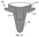
軟組織によって与えられる圧力のみに頼るのではなく、円蓋の各変形例では、軸受け構成要素が基部構成要素と嵌合する状態を維持するために摩擦嵌合又はスナップ嵌合の機構が取り入れられてもよい。一例として、図13〜15は、関節窩基部構成要素302と延伸関節窩軸受け304とを有する肩プロテーゼアセンブリ300を示している。 Rather than relying solely on the pressure applied by the soft tissue, each variation of the circular lid incorporates a friction or snap-fit mechanism to maintain the bearing component mating with the base component. Also good. As an example, FIGS. 13-15 illustrate a
基部構成要素302は、円錐状の部分308と、ネック310と、球根状の空洞312とを備えた嵌合凹部306を有している。延伸関節窩軸受け304は、円錐状の部分316と、ネック318と、球根状の部分320とを備えた嵌合部分314を有している。円錐状の部分316、ネック318、及び球根状の部分320は、それぞれ円錐状の部分308、ネック310、及び球根状の空洞312と相補的に寸法を定められている。しかしながら、球根状の部分320が有する、嵌合部分306の縦軸322に垂直な平面における直径は、ネック310のうちの最も細い部分が存在する平面におけるネック310の直径よりも小さいものである。したがって、嵌合部分306の縦軸324に沿って、球根状の空洞312の中へと、ネック310を越えて球根状の部分320を滑り込ませるためには、球根状の部分320は、いくぶんか圧縮されなければならない。いくつかの実施形態において、球根状の部分320の圧縮を促進するために、空洞が球根状の部分320内に形成されてもよい。 The
本明細書で説明した肩プロテーゼアセンブリの各実施形態の様々な特徴から生じる多数の利点が存在する。留意されたいこととして、肩プロテーゼアセンブリの別の実施形態が、説明した特徴のすべてを有していなくてもよく、それでいて、そのような特徴の利点のうちの少なくとも一部の利益を得ることができる。それらの特徴の1つ以上を取り入れ、添付の特許請求の範囲によって定義される本発明の趣旨及び範囲に含まれる肩プロテーゼアセンブリを独自に実現したものを、当業者は容易に考案することができる。 There are a number of advantages arising from the various features of each embodiment of the shoulder prosthesis assembly described herein. It should be noted that another embodiment of a shoulder prosthesis assembly may not have all of the features described and still benefit from at least some of the advantages of such features. it can. One of ordinary skill in the art can readily devise a unique implementation of a shoulder prosthesis assembly that incorporates one or more of these features and is within the spirit and scope of the invention as defined by the appended claims. .
〔実施の態様〕
(1) 肩甲骨で使用するように構成されたプロテーゼアセンブリであって、前記プロテーゼアセンブリは、
球状の上腕骨構成要素と、
(i)第1の曲率半径を有する第1の球状外側部分と、(ii)第2の曲率半径を有する第2の球状外側部分と、(iii)前記第1の球状外側部分と前記第2の球状外側部分との間に位置する中央部分とを有する第1の軸受け表面と、前記第1の軸受け表面の反対側の第2の軸受け表面から延びる第1の嵌合部分とを有する延伸関節窩軸受け(stretched glenoid bearing)と、
前記延伸関節窩軸受けを回転可能に支持するように構成された基部と、を備え、
前記第1の曲率半径が前記第2の曲率半径と実質的に等しいものであり、前記中央部分が前記第2の曲率半径と実質的に等しい曲率半径を有さない、前記プロテーゼアセンブリ。
(2) 前記基部は、
空洞と、
前記空洞の少なくとも一部分を占有するように構成された空洞占有部分であって、前記第1の嵌合部分と回転可能に嵌合するように構成された第2の嵌合部分を有する前記空洞占有部分と、を備える、実施態様1に記載のプロテーゼアセンブリ。
(3) 前記第1の結合嵌合部は、第1のロック構成要素を有し、
前記第2の嵌合部分は、前記第1のロック構成要素と回転可能に結合するように構成された第2のロック構成要素を有する、実施態様2に記載のプロテーゼアセンブリ。
(4) 前記第1の軸受け表面は、実質的に円形の外周を有する、実施態様1に記載のプロテーゼアセンブリ。
(5) 前記第1の軸受け表面は、非円形の外周を有する、実施態様1に記載のプロテーゼアセンブリ。
(6) 前記中央部分は、実質的に平坦な部分を有する、実施態様5に記載のプロテーゼアセンブリ。
(7) 前記第1の軸受け表面は、非円形の外周を有する、実施態様5に記載のプロテーゼアセンブリ。
(8) 前記基部は、前記延伸関節窩軸受けの回転を360度未満に制限するように構成されている、実施態様1に記載のプロテーゼアセンブリ。
(9) 前記基部は、前記第1の嵌合部分と回転可能に嵌合するように構成された第2の嵌合部分を有し、
前記第1の嵌合部分は、第1のロック構成要素を有し、
前記第2の嵌合部分は、前記第1のロック構成要素と回転可能に結合するように構成された第2のロック構成要素を有する、実施態様8に記載のプロテーゼアセンブリ。
(10) 前記第1のロック構成要素は、前記第1の嵌合部分の外周の周りに延び、
前記第2のロック構成要素は、前記第2の嵌合部分の内周の周りに延び、
前記外周の周りの前記第1のロック構成要素の長さは、前記内周の周りの前記第2のロック構成要素の長さよりも短い、実施態様9に記載のプロテーゼアセンブリ。Embodiment
(1) A prosthesis assembly configured for use with a scapula, the prosthesis assembly comprising:
A spherical humerus component;
(Ii) a first spherical outer portion having a first radius of curvature; (ii) a second spherical outer portion having a second radius of curvature; and (iii) the first spherical outer portion and the second. An extension joint having a first bearing surface having a central portion located between the spherical outer portion and a first mating portion extending from a second bearing surface opposite the first bearing surface A stretched glenoid bearing,
A base configured to rotatably support the elongated glenoid bearing,
The prosthesis assembly, wherein the first radius of curvature is substantially equal to the second radius of curvature and the central portion does not have a radius of curvature substantially equal to the second radius of curvature.
(2) The base is
The cavity,
A cavity occupying portion configured to occupy at least a portion of the cavity, the cavity occupying having a second mating portion configured to rotatably fit with the first mating portion. 2. The prosthesis assembly of embodiment 1, comprising a portion.
(3) The first coupling fitting portion has a first lock component,
The prosthesis assembly of embodiment 2, wherein the second mating portion has a second locking component configured to rotatably couple with the first locking component.
4. The prosthesis assembly according to embodiment 1, wherein the first bearing surface has a substantially circular outer periphery.
5. The prosthesis assembly according to embodiment 1, wherein the first bearing surface has a non-circular perimeter.
6. The prosthesis assembly according to embodiment 5, wherein the central portion has a substantially flat portion.
7. The prosthesis assembly according to embodiment 5, wherein the first bearing surface has a non-circular perimeter.
8. The prosthesis assembly according to embodiment 1, wherein the base is configured to limit rotation of the extended glenoid bearing to less than 360 degrees.
(9) The base has a second fitting portion configured to be rotatably fitted to the first fitting portion,
The first mating portion has a first locking component;
9. The prosthesis assembly of embodiment 8, wherein the second mating portion has a second locking component configured to rotatably couple with the first locking component.
(10) the first locking component extends around an outer periphery of the first mating portion;
The second locking component extends around an inner circumference of the second mating portion;
10. The prosthesis assembly according to embodiment 9, wherein the length of the first locking component around the outer periphery is shorter than the length of the second locking component around the inner periphery.
(11) 肩甲骨で使用するように構成されたプロテーゼアセンブリであって、前記プロテーゼアセンブリは、
球状の上腕骨構成要素と、
(i)第1の曲率半径を有する第1の球状外側部分と、(ii)第2の曲率半径を有する第2の球状外側部分と、(iii)前記第1の球状外側部分と前記第2の球状外側部分との間に位置する中央部分とを有する第1の軸受け表面と、前記第1の軸受け表面の反対側の第2の軸受け表面から延びる第1の嵌合部分とを有する延伸関節窩軸受けと、
第3の軸受け表面と前記第3の軸受け表面から延びる第2の嵌合部分とを有する基部であって、前記延伸関節窩軸受けを回転可能に支持するように構成された、前記基部と、を備え、
前記中央部分が、前記第1の曲率半径又は前記第2の曲率半径と実質的に等しくない曲率半径を有する、前記プロテーゼアセンブリ。
(12) 前記第1の嵌合部分は実質的に円錐状であり、
前記第2の嵌合部分は、前記第1の嵌合部分を受容するように構成されている、実施態様11に記載のプロテーゼアセンブリ。
(13) 前記第3の軸受け表面の周囲は概ね長円状である、実施態様12に記載のプロテーゼアセンブリ。
(14) 前記基部は、
前記第3の軸受け表面の反対側の前記基部側面上の骨接触表面と、
前記骨接触表面から外向きに延びるステムと、を備える、実施態様12に記載のプロテーゼアセンブリ。
(15) 前記基部は金属製であり、前記基部は、
前記ステムから外向きに延びる少なくとも1つのフィンを更に備える、実施態様14に記載のプロテーゼアセンブリ。
(16) 前記第1の嵌合部分は、第1のロック構成要素を有し、
前記第2の嵌合部分は、前記第1のロック構成要素と回転可能に結合するように構成された第2のロック構成要素を有する、実施態様12に記載のプロテーゼアセンブリ。
(17) 前記第1のロック構成要素は、前記第1の嵌合部分の外周の周りに延び、
前記第2のロック構成要素は、前記第2の嵌合部分の内周の周りに延びる、実施態様16に記載のプロテーゼアセンブリ。
(18) 前記基部は、前記延伸関節窩軸受けの回転を360度未満に制限するように構成されている、実施態様17に記載のプロテーゼアセンブリ。
(19) 前記外周の周りの前記第1のロック構成要素の長さは、前記内周の周りの前記第2のロック構成要素の長さよりも短い、実施態様18に記載のプロテーゼアセンブリ。
(20) 前記第1の曲率半径は、前記第2の曲率半径と実質的に等しい、実施態様11に記載のプロテーゼアセンブリ。(11) A prosthesis assembly configured for use with a scapula, the prosthesis assembly comprising:
A spherical humerus component;
(Ii) a first spherical outer portion having a first radius of curvature; (ii) a second spherical outer portion having a second radius of curvature; and (iii) the first spherical outer portion and the second. An extension joint having a first bearing surface having a central portion located between the spherical outer portion and a first mating portion extending from a second bearing surface opposite the first bearing surface Pit bearings,
A base having a third bearing surface and a second mating portion extending from the third bearing surface, the base configured to rotatably support the elongated glenoid bearing; Prepared,
The prosthesis assembly, wherein the central portion has a radius of curvature that is not substantially equal to the first radius of curvature or the second radius of curvature.
(12) The first fitting portion is substantially conical,
12. The prosthesis assembly according to embodiment 11, wherein the second mating portion is configured to receive the first mating portion.
13. The prosthesis assembly according to
(14) The base is
A bone contacting surface on the base side opposite to the third bearing surface;
13. The prosthesis assembly according to
(15) The base is made of metal, and the base is
15. The prosthesis assembly according to
(16) The first fitting portion has a first locking component;
13. The prosthesis assembly according to
(17) the first locking component extends around an outer periphery of the first mating portion;
17. The prosthesis assembly according to
18. The prosthesis assembly according to embodiment 17, wherein the base is configured to limit rotation of the extended glenoid bearing to less than 360 degrees.
19. The prosthesis assembly according to
The prosthesis assembly according to claim 11, wherein the first radius of curvature is substantially equal to the second radius of curvature.
Claims (20)
Translated fromJapanese球状の上腕骨構成要素と、
(i)第1の曲率半径を有する第1の球状外側部分と、(ii)第2の曲率半径を有する第2の球状外側部分と、(iii)前記第1の球状外側部分と前記第2の球状外側部分との間に位置する中央部分とを有する第1の軸受け表面と、前記第1の軸受け表面の反対側の第2の軸受け表面から延びる第1の嵌合部分とを有する延伸関節窩軸受けと、
前記延伸関節窩軸受けを、回転可能に支持するとともに該回転の回転軸方向にはロックする、ように構成された基部と、を備え、
前記第1の曲率半径が前記第2の曲率半径と実質的に等しいものであり、前記中央部分が前記第2の曲率半径と実質的に等しい曲率半径を有さない、前記プロテーゼアセンブリ。A prosthesis assembly configured for use with a scapula, the prosthesis assembly comprising:
A spherical humerus component;
(Ii) a first spherical outer portion having a first radius of curvature; (ii) a second spherical outer portion having a second radius of curvature; and (iii) the first spherical outer portion and the second. An extension joint having a first bearing surface having a central portion located between the spherical outer portion and a first mating portion extending from a second bearing surface opposite the first bearing surface Pit bearings,
It said stretching joint窩軸received, and a configured base lockedto, asin the rotational axis direction of the rotation as well as rotatably supported,
The prosthesis assembly, wherein the first radius of curvature is substantially equal to the second radius of curvature and the central portion does not have a radius of curvature substantially equal to the second radius of curvature.
空洞と、
前記空洞の少なくとも一部分を占有するように構成された空洞占有部分であって、前記第1の嵌合部分と回転可能に嵌合するように構成された第2の嵌合部分を有する前記空洞占有部分と、を備える、請求項1に記載のプロテーゼアセンブリ。The base is
The cavity,
A cavity occupying portion configured to occupy at least a portion of the cavity, the cavity occupying having a second mating portion configured to rotatably fit with the first mating portion. The prosthesis assembly of claim 1, comprising: a portion.
前記第2の嵌合部分は、前記第1のロック構成要素と回転可能に結合するように構成された第2のロック構成要素を有する、請求項2に記載のプロテーゼアセンブリ。The first mating portion has a first locking component;
The prosthesis assembly of claim 2, wherein the second mating portion has a second locking component configured to rotatably couple with the first locking component.
前記第1の嵌合部分は、第1のロック構成要素を有し、
前記第2の嵌合部分は、前記第1のロック構成要素と回転可能に結合するように構成された第2のロック構成要素を有する、請求項8に記載のプロテーゼアセンブリ。The base has a second fitting portion configured to fit rotatably with the first fitting portion;
The first mating portion has a first locking component;
The prosthesis assembly of claim 8, wherein the second mating portion has a second locking component configured to rotatably couple with the first locking component.
前記第2のロック構成要素は、前記第2の嵌合部分の内周の周りに延び、
前記外周の周りの前記第1のロック構成要素の長さは、前記内周の周りの前記第2のロック構成要素の長さよりも短い、請求項9に記載のプロテーゼアセンブリ。The first locking component extends around an outer periphery of the first mating portion;
The second locking component extends around an inner circumference of the second mating portion;
The prosthesis assembly of claim 9, wherein a length of the first locking component around the outer periphery is shorter than a length of the second locking component around the inner periphery.
球状の上腕骨構成要素と、
(i)第1の曲率半径を有する第1の球状外側部分と、(ii)第2の曲率半径を有する第2の球状外側部分と、(iii)前記第1の球状外側部分と前記第2の球状外側部分との間に位置する中央部分とを有する第1の軸受け表面と、前記第1の軸受け表面の反対側の第2の軸受け表面から延びる第1の嵌合部分とを有する延伸関節窩軸受けと、
第3の軸受け表面と前記第3の軸受け表面から延びる第2の嵌合部分とを有する基部であって、前記延伸関節窩軸受けを、回転可能に支持するとともに該回転の回転軸方向にはロックする、ように構成された、前記基部と、を備え、
前記中央部分が、前記第1の曲率半径又は前記第2の曲率半径と実質的に等しくない曲率半径を有する、前記プロテーゼアセンブリ。A prosthesis assembly configured for use with a scapula, the prosthesis assembly comprising:
A spherical humerus component;
(Ii) a first spherical outer portion having a first radius of curvature; (ii) a second spherical outer portion having a second radius of curvature; and (iii) the first spherical outer portion and the second. An extension joint having a first bearing surface having a central portion located between the spherical outer portion and a first mating portion extending from a second bearing surface opposite the first bearing surface Pit bearings,
A base having a second mating portion extending from the third bearing surface and the third bearing surface, lockingin the direction of the rotation axis of the rotating together with the stretched joint窩軸receivedrotatably supportsto, configured to, and a the base,
The prosthesis assembly, wherein the central portion has a radius of curvature that is not substantially equal to the first radius of curvature or the second radius of curvature.
前記第2の嵌合部分は、前記第1の嵌合部分を受容するように構成されている、請求項11に記載のプロテーゼアセンブリ。The first mating portion is substantially conical;
The prosthesis assembly of claim 11, wherein the second mating portion is configured to receive the first mating portion.
前記第3の軸受け表面の反対側の前記基部側面上の骨接触表面と、
前記骨接触表面から外向きに延びるステムと、を備える、請求項12に記載のプロテーゼアセンブリ。The base is
A bone contacting surface on the base side opposite to the third bearing surface;
The prosthesis assembly of claim 12, comprising a stem extending outwardly from the bone contacting surface.
前記ステムから外向きに延びる少なくとも1つのフィンを更に備える、請求項14に記載のプロテーゼアセンブリ。The base is made of metal, and the base is
The prosthesis assembly of claim 14, further comprising at least one fin extending outwardly from the stem.
前記第2の嵌合部分は、前記第1のロック構成要素と回転可能に結合するように構成された第2のロック構成要素を有する、請求項12に記載のプロテーゼアセンブリ。The first mating portion has a first locking component;
The prosthesis assembly of claim 12, wherein the second mating portion has a second locking component configured to rotatably couple with the first locking component.
前記第2のロック構成要素は、前記第2の嵌合部分の内周の周りに延びる、請求項16に記載のプロテーゼアセンブリ。The first locking component extends around an outer periphery of the first mating portion;
The prosthesis assembly of claim 16, wherein the second locking component extends around an inner circumference of the second mating portion.
Applications Claiming Priority (3)
| Application Number | Priority Date | Filing Date | Title |
|---|---|---|---|
| US33145810P | 2010-05-05 | 2010-05-05 | |
| US61/331,458 | 2010-05-05 | ||
| PCT/US2011/035144WO2011140191A1 (en) | 2010-05-05 | 2011-05-04 | Mobile bearing glenoid prosthesis |
Publications (2)
| Publication Number | Publication Date |
|---|---|
| JP2013528427A JP2013528427A (en) | 2013-07-11 |
| JP5844351B2true JP5844351B2 (en) | 2016-01-13 |
Family
ID=44227973
Family Applications (1)
| Application Number | Title | Priority Date | Filing Date |
|---|---|---|---|
| JP2013509211AActiveJP5844351B2 (en) | 2010-05-05 | 2011-05-04 | Mobile bearing glenoid prosthesis |
Country Status (7)
| Country | Link |
|---|---|
| US (2) | US8882845B2 (en) |
| EP (1) | EP2566417B1 (en) |
| JP (1) | JP5844351B2 (en) |
| AU (1) | AU2011248202B2 (en) |
| DK (1) | DK2566417T3 (en) |
| ES (1) | ES2485365T3 (en) |
| WO (1) | WO2011140191A1 (en) |
Families Citing this family (60)
| Publication number | Priority date | Publication date | Assignee | Title |
|---|---|---|---|---|
| US8388624B2 (en) | 2003-02-24 | 2013-03-05 | Arthrosurface Incorporated | Trochlear resurfacing system and method |
| US8778028B2 (en) | 2005-02-25 | 2014-07-15 | Shoulder Innovations, Inc. | Methods and devices for less invasive glenoid replacement |
| US8007538B2 (en) | 2005-02-25 | 2011-08-30 | Shoulder Innovations, Llc | Shoulder implant for glenoid replacement |
| US20230080207A1 (en) | 2005-02-25 | 2023-03-16 | Shoulder Innovations, Inc. | Methods and devices for less invasive glenoid replacement |
| US9358029B2 (en) | 2006-12-11 | 2016-06-07 | Arthrosurface Incorporated | Retrograde resection apparatus and method |
| US20090287309A1 (en) | 2007-01-30 | 2009-11-19 | Tornier Sas | Intra-articular joint replacement |
| WO2010121250A1 (en) | 2009-04-17 | 2010-10-21 | Arthrosurface Incorporated | Glenoid resurfacing system and method |
| US10945743B2 (en) | 2009-04-17 | 2021-03-16 | Arthrosurface Incorporated | Glenoid repair system and methods of use thereof |
| EP2542165A4 (en) | 2010-03-05 | 2015-10-07 | Arthrosurface Inc | Tibial resurfacing system and method |
| USD685474S1 (en) | 2010-07-06 | 2013-07-02 | Tornier, Inc. | Prosthesis anchor |
| FR2971144A1 (en) | 2011-02-08 | 2012-08-10 | Tornier Sa | GLENOIDAL IMPLANT FOR SHOULDER PROSTHESIS AND SURGICAL KIT |
| FR2978912A1 (en) | 2011-08-10 | 2013-02-15 | Tornier Inc | ANCILLARY EXTRACTION OF A PROSTHESIS |
| EP2804565B1 (en) | 2011-12-22 | 2018-03-07 | Arthrosurface Incorporated | System for bone fixation |
| WO2014008126A1 (en) | 2012-07-03 | 2014-01-09 | Arthrosurface Incorporated | System and method for joint resurfacing and repair |
| CA2907537C (en)* | 2012-08-01 | 2020-08-25 | Exactech, Inc. | Prosthetic devices to improve joint mechanics in arthroplasty |
| USD760900S1 (en) | 2012-12-13 | 2016-07-05 | Shoulder Options, Inc. | Keeled glenoid |
| US10973646B2 (en) | 2013-03-11 | 2021-04-13 | Catalyst Orthoscience Inc. | Stabilized drill guide |
| USD730522S1 (en) | 2013-03-11 | 2015-05-26 | Catalyst Orthopaedics Llc | Implant |
| US11007063B2 (en) | 2013-03-11 | 2021-05-18 | Catalyst Orthoscience Inc. | Offset reamers |
| US20170319348A1 (en) | 2015-08-10 | 2017-11-09 | Catalyst Orthoscience Inc. | Arthroplasty prostheses with multi-axis fixation |
| US9044330B2 (en)* | 2013-03-12 | 2015-06-02 | DePuy Synthes Products, Inc. | System and method for implanting a secondary glenoid prosthesis |
| US9492200B2 (en) | 2013-04-16 | 2016-11-15 | Arthrosurface Incorporated | Suture system and method |
| US9962266B2 (en) | 2015-09-11 | 2018-05-08 | Deltoid, Llc | Arthroplasty components |
| US10433969B2 (en) | 2013-12-30 | 2019-10-08 | United Orthopedic Corp. | Arthroplasty implants and methods for orienting joint prosthesis |
| US10456264B2 (en) | 2014-01-24 | 2019-10-29 | Tornier, Inc. | Humeral implant anchor system |
| US12023253B2 (en) | 2014-01-24 | 2024-07-02 | Howmedica Osteonics Corp. | Humeral implant anchor system |
| US10624748B2 (en) | 2014-03-07 | 2020-04-21 | Arthrosurface Incorporated | System and method for repairing articular surfaces |
| US11607319B2 (en) | 2014-03-07 | 2023-03-21 | Arthrosurface Incorporated | System and method for repairing articular surfaces |
| US9931219B2 (en) | 2014-03-07 | 2018-04-03 | Arthrosurface Incorporated | Implant and anchor assembly |
| US9681960B2 (en) | 2014-05-16 | 2017-06-20 | Howmedica Osteonics Corp. | Guides for fracture system |
| US10575968B2 (en) | 2014-05-16 | 2020-03-03 | Howmedica Osteonics Corp. | Guides for fracture system |
| US10492926B1 (en) | 2014-09-04 | 2019-12-03 | Shoulder Innovations, Inc. | Alignment guide for humeral or femoral stem replacement prostheses |
| USD835276S1 (en) | 2015-09-11 | 2018-12-04 | United Orthopedic Corporation | Keeled glenoid |
| EP3178446B1 (en)* | 2015-12-03 | 2019-07-03 | Zimmer, Inc. | Multi-curvature liners for reversed shoulder replacement |
| JP6703144B2 (en) | 2016-02-28 | 2020-06-03 | コンソーシアム オブ フォーカスド オーソペディスツ, エルエルシー | Shoulder arthroplasty implant system |
| US11833055B2 (en) | 2016-02-28 | 2023-12-05 | Integrated Shoulder Collaboration, Inc. | Shoulder arthroplasty implant system |
| US10463499B2 (en) | 2016-03-25 | 2019-11-05 | Tornier, Inc. | Stemless shoulder implant with fixation components |
| KR102525770B1 (en)* | 2016-06-15 | 2023-04-26 | 삼성전자주식회사 | Apparatus and method for positioning terminal in wireless communicatnon system |
| EP3484416A1 (en)* | 2016-07-18 | 2019-05-22 | Catalyst Orthoscience Inc. | Arthroplasty prostheses with multi-axis fixation |
| US11129724B2 (en) | 2016-07-28 | 2021-09-28 | Howmedica Osteonics Corp. | Stemless prosthesis anchor component |
| CA3051099C (en) | 2017-01-20 | 2022-07-12 | Biomet Manufacturing, Llc | Modular augment component |
| EP4520302A3 (en) | 2017-04-14 | 2025-04-16 | Shoulder Innovations, Inc. | Total shoulder prosthesis having inset glenoid implant convertible from anatomic to reverse |
| US11160663B2 (en) | 2017-08-04 | 2021-11-02 | Arthrosurface Incorporated | Multicomponent articular surface implant |
| MX2020003194A (en) | 2017-09-25 | 2020-12-09 | Howmedica Osteonics Corp | Patient specific stemless prosthesis anchor components. |
| US11399948B2 (en) | 2017-12-11 | 2022-08-02 | Howmedica Osteonics Corp. | Stemless prosthesis anchor components and kits |
| US12138172B2 (en) | 2018-04-30 | 2024-11-12 | Shoulder Innovations, Inc. | Inset/onlay glenoid, porous coated convertible glenoid, and humeral heads with textured undersides |
| EP4257090A3 (en) | 2018-10-02 | 2023-12-13 | Howmedica Osteonics Corp. | Shoulder prosthesis components and assemblies |
| AU2020237088B2 (en) | 2019-03-11 | 2025-09-04 | Shoulder Innovations, Inc. | Total reverse shoulder systems and methods |
| USD977643S1 (en) | 2019-03-12 | 2023-02-07 | Shoulder Innovations, Inc. | Humeral stem implant |
| WO2020186099A1 (en) | 2019-03-12 | 2020-09-17 | Arthrosurface Incorporated | Humeral and glenoid articular surface implant systems and methods |
| NL1043315B1 (en)* | 2019-06-27 | 2021-02-01 | Jointsphere B V | Plug-shaped implant for the replacement and regeneration of biological tissue and method for preparing the implant |
| AU2020207869A1 (en) | 2019-08-01 | 2021-02-18 | Howmedica Osteonics Corp. | Hybrid metal-backed glenoid component |
| EP3982848A1 (en) | 2019-08-09 | 2022-04-20 | Howmedica Osteonics Corp. | Apparatuses and methods for implanting glenoid prostheses |
| EP4527357A3 (en) | 2019-10-01 | 2025-06-04 | Howmedica Osteonics Corporation | Shoulder prosthesis components and assemblies |
| USD951449S1 (en) | 2019-10-01 | 2022-05-10 | Howmedica Osteonics Corp. | Humeral implant |
| EP4093336A1 (en)* | 2020-01-24 | 2022-11-30 | Zimmer, Inc. | Mobile bearing reversed humeral implant |
| CN111407470A (en)* | 2020-04-20 | 2020-07-14 | 北京市春立正达医疗器械股份有限公司 | Glenoid prosthesis and shoulder joint prosthesis applying same |
| AU2021204625A1 (en)* | 2020-07-06 | 2022-01-20 | Howmedica Osteonics Corp. | Anatomic implant for joints |
| WO2025064466A1 (en)* | 2023-09-21 | 2025-03-27 | Arthrex, Inc. | Constrained orthopaedic implants and methods of repair |
| WO2025151535A1 (en)* | 2024-01-08 | 2025-07-17 | Hyalex Orthopaedics, Inc. | Metatarsophalangeal joint implants and methods thereof |
Family Cites Families (15)
| Publication number | Priority date | Publication date | Assignee | Title |
|---|---|---|---|---|
| US4261062A (en)* | 1979-03-22 | 1981-04-14 | The Regents Of The University Of California | Natural shoulder joint prosthesis |
| GB2297257A (en) | 1995-01-24 | 1996-07-31 | Corin Medical Ltd | Shoulder prosthesis with meniscal component |
| FR2755847B1 (en) | 1996-10-11 | 1999-01-29 | Medinov Amp | PROSTHETIC ASSEMBLY FOR THE SHOULDER JOINT |
| US5928285A (en)* | 1997-05-30 | 1999-07-27 | Bristol-Myers Squibb Co. | Orthopaedic implant having an articulating surface with a conforming and translational surface |
| US6911047B2 (en) | 2000-03-17 | 2005-06-28 | Depuy Orthopaedics, Inc. | Apparatus and method for securing a cementless glenoid component to a glenoid surface of a scapula |
| FR2825263A1 (en) | 2001-05-30 | 2002-12-06 | Tecknimed | Shoulder joint prosthesis has cap on humerus to engage socket with movement limiting stop surfaces |
| FR2859099B1 (en)* | 2003-08-25 | 2006-01-06 | Tornier Sa | GLENOIDAL COMPONENT OF SHOULDER PROSTHESIS AND TOTAL SHOULDER PROSTHESIS INCORPORATING SUCH COMPONENT |
| GB0320287D0 (en)* | 2003-08-29 | 2003-10-01 | Stanmore Implants Worldwide | Shoulder joint prosthetic system |
| ATE503442T1 (en) | 2004-05-19 | 2011-04-15 | Zimmer Gmbh | GLENOID ANCHORAGE |
| US7922769B2 (en)* | 2004-09-27 | 2011-04-12 | Depuy Products, Inc. | Modular glenoid prosthesis and associated method |
| EP1945151A4 (en)* | 2005-10-31 | 2009-09-09 | Depuy Products Inc | Modular fixed and mobile bearing prosthesis system |
| US7708783B2 (en)* | 2005-11-04 | 2010-05-04 | Zimmer Technology, Inc. | Rotating constrained liner |
| EP1787603A1 (en) | 2005-11-18 | 2007-05-23 | Zimmer GmbH | Basis-platform for an artificial joint |
| US9549820B2 (en)* | 2009-06-25 | 2017-01-24 | Zimmer, Inc. | Glenoid implant with synthetic labrum |
| US8231683B2 (en)* | 2009-12-08 | 2012-07-31 | Depuy Products, Inc. | Shoulder prosthesis assembly having glenoid rim replacement structure |
- 2011
- 2011-04-26USUS13/094,180patent/US8882845B2/enactiveActive
- 2011-05-04AUAU2011248202Apatent/AU2011248202B2/enactiveActive
- 2011-05-04JPJP2013509211Apatent/JP5844351B2/enactiveActive
- 2011-05-04DKDK11721168.0Tpatent/DK2566417T3/enactive
- 2011-05-04EPEP11721168.0Apatent/EP2566417B1/enactiveActive
- 2011-05-04ESES11721168.0Tpatent/ES2485365T3/enactiveActive
- 2011-05-04WOPCT/US2011/035144patent/WO2011140191A1/enactiveApplication Filing
- 2014
- 2014-10-06USUS14/507,446patent/US9439769B2/enactiveActive
Also Published As
| Publication number | Publication date |
|---|---|
| WO2011140191A1 (en) | 2011-11-10 |
| US9439769B2 (en) | 2016-09-13 |
| US20110276144A1 (en) | 2011-11-10 |
| AU2011248202A1 (en) | 2012-11-08 |
| US8882845B2 (en) | 2014-11-11 |
| EP2566417B1 (en) | 2014-06-04 |
| AU2011248202B2 (en) | 2014-08-07 |
| EP2566417A1 (en) | 2013-03-13 |
| JP2013528427A (en) | 2013-07-11 |
| US20150025642A1 (en) | 2015-01-22 |
| ES2485365T3 (en) | 2014-08-13 |
| DK2566417T3 (en) | 2014-08-11 |
Similar Documents
| Publication | Publication Date | Title |
|---|---|---|
| JP5844351B2 (en) | Mobile bearing glenoid prosthesis | |
| KR101440961B1 (en) | Scapular artificial prosthesis | |
| US8845743B2 (en) | Interlocking reverse shoulder prosthesis method | |
| EP2676635B1 (en) | Constrained mobile bearing hip assembly | |
| EP1996123B1 (en) | Non-spherical articulating surfaces in shoulder and hip prosthesis | |
| US7323012B1 (en) | Ankle implant | |
| US7108720B2 (en) | Reduced wear orthopaedic implant apparatus and method | |
| JP2019517342A (en) | Elbow joint replacement device and method | |
| JP2004522509A (en) | Containment system for restraining prosthetic components | |
| JPH0550290B2 (en) | ||
| US20250000662A1 (en) | Stemless, convertible, humeral shoulder prosthesis | |
| US20230000636A1 (en) | Replacement member for a joint replacement | |
| JP2019531139A (en) | Lateral double movable assembly | |
| US12245946B2 (en) | Modular reverse shoulder prosthesis | |
| US20220249241A1 (en) | Reverse shoulder prosthesis and related methods | |
| US20250017737A1 (en) | Reverse shoulder prosthesis and related methods | |
| WO2025059049A1 (en) | Reverse shoulder prosthesis and related methods | |
| JP2023505341A (en) | Anchoring member for joint replacement |
Legal Events
| Date | Code | Title | Description |
|---|---|---|---|
| A621 | Written request for application examination | Free format text:JAPANESE INTERMEDIATE CODE: A621 Effective date:20140304 | |
| A977 | Report on retrieval | Free format text:JAPANESE INTERMEDIATE CODE: A971007 Effective date:20141128 | |
| A131 | Notification of reasons for refusal | Free format text:JAPANESE INTERMEDIATE CODE: A131 Effective date:20141202 | |
| A521 | Request for written amendment filed | Free format text:JAPANESE INTERMEDIATE CODE: A523 Effective date:20150206 | |
| A131 | Notification of reasons for refusal | Free format text:JAPANESE INTERMEDIATE CODE: A131 Effective date:20150714 | |
| A711 | Notification of change in applicant | Free format text:JAPANESE INTERMEDIATE CODE: A711 Effective date:20150727 | |
| A521 | Request for written amendment filed | Free format text:JAPANESE INTERMEDIATE CODE: A523 Effective date:20151008 | |
| TRDD | Decision of grant or rejection written | ||
| A01 | Written decision to grant a patent or to grant a registration (utility model) | Free format text:JAPANESE INTERMEDIATE CODE: A01 Effective date:20151110 | |
| A61 | First payment of annual fees (during grant procedure) | Free format text:JAPANESE INTERMEDIATE CODE: A61 Effective date:20151118 | |
| R150 | Certificate of patent or registration of utility model | Ref document number:5844351 Country of ref document:JP Free format text:JAPANESE INTERMEDIATE CODE: R150 | |
| R250 | Receipt of annual fees | Free format text:JAPANESE INTERMEDIATE CODE: R250 | |
| R250 | Receipt of annual fees | Free format text:JAPANESE INTERMEDIATE CODE: R250 | |
| R250 | Receipt of annual fees | Free format text:JAPANESE INTERMEDIATE CODE: R250 | |
| R250 | Receipt of annual fees | Free format text:JAPANESE INTERMEDIATE CODE: R250 | |
| R250 | Receipt of annual fees | Free format text:JAPANESE INTERMEDIATE CODE: R250 | |
| R250 | Receipt of annual fees | Free format text:JAPANESE INTERMEDIATE CODE: R250 | |
| R250 | Receipt of annual fees | Free format text:JAPANESE INTERMEDIATE CODE: R250 |