JP5843637B2 - Image forming apparatus, image forming apparatus control method, and program - Google Patents
Image forming apparatus, image forming apparatus control method, and programDownload PDFInfo
- Publication number
- JP5843637B2 JP5843637B2JP2012019898AJP2012019898AJP5843637B2JP 5843637 B2JP5843637 B2JP 5843637B2JP 2012019898 AJP2012019898 AJP 2012019898AJP 2012019898 AJP2012019898 AJP 2012019898AJP 5843637 B2JP5843637 B2JP 5843637B2
- Authority
- JP
- Japan
- Prior art keywords
- update
- setting
- update process
- history
- image forming
- Prior art date
- Legal status (The legal status is an assumption and is not a legal conclusion. Google has not performed a legal analysis and makes no representation as to the accuracy of the status listed.)
- Expired - Fee Related
Links
Images


Classifications
- G—PHYSICS
- G06—COMPUTING OR CALCULATING; COUNTING
- G06F—ELECTRIC DIGITAL DATA PROCESSING
- G06F1/00—Details not covered by groups G06F3/00 - G06F13/00 and G06F21/00
- G06F1/24—Resetting means
- G—PHYSICS
- G06—COMPUTING OR CALCULATING; COUNTING
- G06F—ELECTRIC DIGITAL DATA PROCESSING
- G06F8/00—Arrangements for software engineering
- G06F8/60—Software deployment
- G06F8/65—Updates
- G—PHYSICS
- G06—COMPUTING OR CALCULATING; COUNTING
- G06F—ELECTRIC DIGITAL DATA PROCESSING
- G06F8/00—Arrangements for software engineering
- G06F8/60—Software deployment
- G06F8/65—Updates
- G06F8/654—Updates using techniques specially adapted for alterable solid state memories, e.g. for EEPROM or flash memories
- G—PHYSICS
- G06—COMPUTING OR CALCULATING; COUNTING
- G06F—ELECTRIC DIGITAL DATA PROCESSING
- G06F9/00—Arrangements for program control, e.g. control units
- G06F9/06—Arrangements for program control, e.g. control units using stored programs, i.e. using an internal store of processing equipment to receive or retain programs
- G06F9/44—Arrangements for executing specific programs
- G06F9/445—Program loading or initiating
- G06F9/44505—Configuring for program initiating, e.g. using registry, configuration files
Landscapes
- Engineering & Computer Science (AREA)
- Theoretical Computer Science (AREA)
- General Engineering & Computer Science (AREA)
- Software Systems (AREA)
- Physics & Mathematics (AREA)
- General Physics & Mathematics (AREA)
- Computer Security & Cryptography (AREA)
- Stored Programmes (AREA)
- Accessory Devices And Overall Control Thereof (AREA)
- Facsimiles In General (AREA)
Description
Translated fromJapanese本発明は、ファームウェアの更新機能を備える画像形成装置、画像形成装置の制御方法、及びプログラムに関する。 The present invention relates to an image forming apparatus having a firmware update function, an image forming apparatus control method, and a program.
近年、デジタル複合機等の画像形成装置においては、製品出荷後に市場でファームウェア(制御プログラム)の更新(アップデート、バージョンアップ)が可能なものが一般的となっている。 2. Description of the Related Art In recent years, image forming apparatuses such as digital multifunction peripherals are generally capable of updating (updating, upgrading) firmware (control programs) on the market after product shipment.
更新用ファームウェアは、機能追加、仕様変更、又はソフトウェア不具合の修正等、様々な理由により提供されるため、同じ製品に対して頻繁にファームウェアの更新を実施する場合がある。そのため、ファームウェアの更新履歴を記憶して管理することが可能な画像形成装置が提案されている(特許文献1参照)。 The update firmware is provided for various reasons such as addition of a function, specification change, or correction of a software defect, and therefore the firmware may be frequently updated for the same product. Therefore, an image forming apparatus capable of storing and managing firmware update history has been proposed (see Patent Document 1).
デジタル複合機等の画像形成装置においては、装置ごとの調整値、両面印刷などの印刷処理に係る初期設定、各機能の動作仕様に係る設定等、様々な機器設定(設定項目)に対して設定値を登録可能になっているが、ファームウェアの更新前後で当該設定項目や設定値が変更される場合がある。 In image forming apparatuses such as digital multifunction peripherals, settings are made for various device settings (setting items) such as adjustment values for each apparatus, initial settings for printing processing such as double-sided printing, and settings for operation specifications of each function. Although the value can be registered, the setting item and the setting value may be changed before and after the firmware update.
例えば、機能追加を伴ったファームウェアの更新を実施する場合、追加された機能の動作仕様に係る設定項目は、ファームウェア更新前の装置状態には存在しない。また、仕様変更により、ある設定項目に対して設定可能な設定値の値域が変更された場合、仕様変更後の値域に合わせてファームウェア更新前の設定値を自動的に補正し、ファームウェア更新後の設定値として登録するケースもある。このようなファームウェア更新に伴う設定値の変更にユーザが気付かない場合、本来ユーザが望まない設定値のまま装置を使用してしまう恐れがある。 For example, when updating firmware with function addition, the setting items related to the operation specifications of the added function do not exist in the device state before firmware update. In addition, when the range of setting values that can be set for a setting item is changed due to a specification change, the setting value before the firmware update is automatically corrected according to the value range after the specification change. In some cases, it is registered as a setting value. If the user is not aware of such a change in the setting value associated with the firmware update, the apparatus may be used with the setting value that the user originally does not want.
ファームウェア更新に伴う設定値の変更にユーザが後から気付いた場合、ユーザは設定値を所望の設定に戻そうとすると考えられる。しかしながら、上述の従来の技術では、ファームウェアの更新結果、およびバージョン情報をユーザに通知することはできるものの、ファームウェア更新に伴う設定値の変更をユーザに通知することはできなかった。また、画像形成装置の仕様に詳しくないユーザであれば、変更された設定値を戻そうとしてもどのような設定値に戻せばいいのか分からない場合もある If the user later notices a change in the setting value associated with the firmware update, the user is likely to return the setting value to a desired setting. However, although the above-described conventional technology can notify the user of the firmware update result and the version information, it cannot notify the user of the change in the setting value accompanying the firmware update. In addition, if the user is not familiar with the specifications of the image forming apparatus, there is a case where it is not possible to know what setting value should be returned even if the changed setting value is returned.
本発明は、上記の問題点を解決するためになされたものである。本発明の目的は、更新履歴に対応付けられた設定値の変更に関する情報をユーザが確認できる仕組みを提供することである。 The present invention has been made to solve the above problems. An object of the present invention is to provide a mechanism by which a user can check information related to a change in a setting value associated with an update history.
本発明は、印刷を実行可能な画像形成装置であって、前記画像形成装置のファームェアを更新するための更新処理を実行する更新手段と、前記更新手段が前記更新処理を実行した場合に、前記更新処理によって追加された設定項目と、前記更新処理によって削除された設定項目と、前記更新処理によって変更された設定項目の変更前の設定値と、前記更新処理によって変更された設定項目の変更後の設定値とを示す設定差分情報を生成する生成手段と、前記生成手段によって生成された前記設定差分情報を更新履歴に対応付けて蓄積する蓄積手段と、前記更新処理に関する更新履歴画面を表示する表示手段と、を備え、前記更新履歴画面において複数の更新履歴の中から特定の更新履歴をユーザが選択した場合に、前記表示手段は、前記特定の更新履歴に対応する前記設定差分情報に基づいて、前記特定の更新履歴が示す更新処理によって追加された設定項目と、前記特定の更新履歴が示す更新処理によって削除された設定項目と、前記特定の更新履歴が示す更新処理によって変更された設定項目の変更前の設定値と、前記特定の更新履歴が示す更新処理によって変更された設定項目の変更後の設定値とを表示することを特徴とする。 The present invention is an image forming apparatus capable of executing printing, an update unit for executing update processing for updating firmware of the image forming device, and when the update unit executes the update processing, Setting item added by update process, setting item deleted by update process, setting value before change of setting item changed by update process, and after change of setting item changed by update process A generating unit that generates setting difference information indicating a set value of the data, a storage unit that stores the setting difference information generated by the generating unit in association with an update history, and an update history screen related to the update process. Display means, and when the user selects a specific update history from a plurality of update histories on the update history screen, the display means Based on the setting difference information corresponding to the update history, the setting item added by the update process indicated by the specific update history, the setting item deleted by the update process indicated by the specific update history, and the specific A setting value before the change of the setting item changed by the update process indicated by the update history and a setting value after the change of the setting item changed by the update process indicated by the specific update history are displayed. .
本発明によれば、更新履歴に対応付けられた設定値の変更に関する情報をユーザが確認できる。 According to the present invention, the user can check information related to the change of the setting value associated with the update history.
以下、本発明を実施するための形態について図面を用いて説明する。 Hereinafter, embodiments for carrying out the present invention will be described with reference to the drawings.
図1は、本発明の一実施例を示す画像形成装置を含むシステム構成図である。
図1において、MFP(Multi Function Peripheral)1は本実施例の画像形成装置であり、コピー、スキャン、プリント、SEND(画像データ送信)、RECEIVE(画像データ受信)などの機能を有する。MFP1は、ネットワーク2を介して配信サーバ3と接続されている。FIG. 1 is a system configuration diagram including an image forming apparatus according to an embodiment of the present invention.
In FIG. 1, an MFP (Multi Function Peripheral) 1 is an image forming apparatus according to this embodiment, and has functions such as copy, scan, print, SEND (image data transmission), and RECEIVE (image data reception). The MFP 1 is connected to the distribution server 3 via the
ネットワーク2は、例えば、イーサネット(登録商標)等から構成されている。配信サーバ3は、少なくとも1機種以上の画像処理装置の更新ファームウェアを保持している。配信サーバ3は、更新ファームウェアが登録されると、更新対象となる装置を検索し、該当する装置へ更新ファームウェアを送信する。 The
MFP1は、配信サーバ3から送信された更新ファームウェアを受信し、自身のファームウェアを更新する。なお、MFP1と配信サーバ3とは、HTTP(Hypertext Transfer Protocol)/SOAP(Simple Object Access Protocol)といった公知のネットワーク通信プロトコルを用いて通信を行うため、通信手順等の詳細説明は割愛する。 The MFP 1 receives the update firmware transmitted from the distribution server 3 and updates its own firmware. Since the
<画像形成装置のハードウェア構成>
以下、図2を用いて、本発明の実施例に係る画像形成装置のハードウェア構成について説明する。<Hardware configuration of image forming apparatus>
Hereinafter, the hardware configuration of the image forming apparatus according to the embodiment of the present invention will be described with reference to FIG.
図2は、MFP1のハードウェア構成の一例を示すブロック図である。
図2において、100はメインコントローラ(Controller MainUnit)であり、MFP1の情報処理部を司る。101はサブコントローラ(Controller SubUnit)であり、MFP1の画像処理部を司る。メインコントローラ100とサブコントローラ101とは、バスブリッジ(BusBridge)116を介してバス間で接続されている。FIG. 2 is a block diagram illustrating an example of the hardware configuration of the
In FIG. 2,
まず、メインコントローラ100の構成要素を説明する。
メインコントローラ100において、CPU1(108)は、システムバス115に接続される各デバイスを総括的に制御する。CPU1(108)は、フラッシュROM(FLASH ROM)110、或いはハードディスク(HDD)111に記憶された制御プログラム(ファームウェア)を実行する。First, components of the
In the
フラッシュROM110、或いはHDD111は、プログラムのみでなく、画像データや各機能の動作仕様に係る機器設定、各種履歴データの記憶領域としても使われる。RAM1(109)は、CPU1(108)の主メモリ、ワークエリア等として機能する。 The
操作部I/F112は、LCDパネル104に各機能に係る操作画面や装置状態画面などを描画する。また、操作部I/F112には、操作ボタン及び/或いはタッチパネル103も接続されている。操作ボタン及び/或いはタッチパネル103は、LCDパネル104と一体になっており、オペレータの指示入力を制御する。 The operation unit I /
ネットワークインタフェース部(Network I/F)113は、他のネットワーク機器や図1記載の配信サーバ3とLAN102を介して双方向にデータをやりとりする。 A network interface unit (Network I / F) 113 exchanges data bidirectionally with other network devices and the distribution server 3 shown in FIG.
外部シリアルインタフェース(外部シリアルI/F)114は、例えばUSBであり、メモリメディアリーダ、或いはICカードリーダなどの外部装置を接続し、双方向にデータをやりとりする。 次に、サブコントローラ101の構成要素を説明する。 An external serial interface (external serial I / F) 114 is, for example, a USB, and is connected to an external device such as a memory media reader or an IC card reader to exchange data bidirectionally. Next, components of the
プリンタ106は、例えば電子写真方式あるいはインクジェット方式などで実現される印刷メディアへの印字部である。スキャナ105は、原稿メディアに印字された画像を読み込むための画像読み取り部である。多くの場合、スキャナ105には、オプションとしてオートドキュメントフィーダ(不図示)が装着されており、複数枚の原稿を自動的に読み込むことができる。プリンタ106及びスキャナ105は、デバイスインタフェース(デバイスI/F)120を通して制御信号をCPU2(117)との間で授受する。 The
CPU2(117)は、システムバス127に接続される各デバイスを総括的に制御する。スキャナ105から入力される画像は、スキャナ画像処理部121を介してRAM2(118)に読み取り画像として入力される。 The CPU 2 (117) comprehensively controls each device connected to the
メモリ画像処理部(IMAGEC)123は、RAM2(118)上の読み取り画像に所定の画像処理を施してRAM2(118)に出力する。このメモリ画像処理部123による画像処理には、回転・変倍・色空間変換・グレースケール変換・合成・符号化・復号化などの処理が含まれる。 The memory image processing unit (IMAGEC) 123 performs predetermined image processing on the read image on the RAM 2 (118) and outputs the processed image to the RAM 2 (118). The image processing by the memory
CPU2(117)は、RAM2(118)上の画像を、メモリ画像処理部123で画像処理後に、バスブリッジ116を介して、メインコントローラ100上の記憶装置(フラッシュROM110やHDD111)に保存する。 The CPU 2 (117) stores the image on the RAM 2 (118) in the storage device (
また、CPU2(117)は、バスブリッジ116を介して、メインコントローラ100上の記憶装置(フラッシュROM110やHDD111)に保存されている画像をRAM2(118)に読み出し、プリンタ画像処理部122を経由してプリンタ106に出力する。なお、スキャナ画像処理部121及びプリンタ画像処理部122で行う画像処理には、色空間変換、移動、色調整、濃度制御、遅延量制御が含まれる。 Further, the CPU 2 (117) reads an image stored in the storage device (
ラスターイメージプロセッサ(RIP)119は、RAM2(118)上のPDLコードをビットマップイメージに展開し、RAM2(118)に出力する。SRAM124は、CPU2(117)との間で不揮発データを高速に入出力する。MODEM125は、公衆回線107に接続し、ファクス画像入出力に伴う変復調を行う。 The raster image processor (RIP) 119 expands the PDL code on the RAM 2 (118) into a bitmap image and outputs it to the RAM 2 (118). The
なお、CPU1(108)及びCPU2(117)により実行される制御プログラム(ファームウェア)は、少なくとも2つ以上のモジュールから構成され、ファームウェアの更新は、それぞれのモジュールごとに行うことが可能である。 Note that the control program (firmware) executed by the CPU 1 (108) and the CPU 2 (117) is composed of at least two modules, and the firmware can be updated for each module.
<画像形成装置のソフトウェア構成>
以下、図3を用いて、本実施例に係る画像形成装置のソフトウェア構成について説明する。<Software configuration of image forming apparatus>
Hereinafter, the software configuration of the image forming apparatus according to the present exemplary embodiment will be described with reference to FIG.
図3は、MFP1のソフトウェア構成の一例を示すソフトブロック図である。なお、MFP1のファームウェアは図3に記載した以外のソフトブロックも含むが、本発明の構成と直接関係しないものに関しては図示していない。 FIG. 3 is a software block diagram illustrating an example of the software configuration of the
図3において、ネットワーク制御モジュール301は、ネットワーク通信を実現するモジュールである。ネットワーク制御モジュール301は、ネットワークインタフェース113を制御すると共に、各種通信プロトコルに応じたソフト的な通信制御によりデータの入出力を行う。本実施例においては、ネットワーク制御モジュール301は、配信サーバ3との通信制御を司り、更新ファームウェアの受信処理を行う。 In FIG. 3, a
アップデート制御モジュール302は、前記更新ファームウェアを用いてフラッシュROM110或いはHDD111に記憶されたMFP1のファームウェアの更新(アップデート)処理を制御するモジュールである。 The
機器設定エクスポートモジュール303は、アップデート制御モジュール302の指示により、ファームウェア更新前、及びファームウェア更新後の各種設定値全てを読み出し、XML(eXtensible Markup Language)形式への変換を行う。 In response to an instruction from the
機器設定差分抽出モジュール304は、アップデート制御モジュール302の指示により、上述の機器設定エクスポートモジュール303によって取得した情報(ファームウェア更新前後の機器設定値(XML形式))を基にファームウェア更新前後の機器設定値の差分抽出を行う。 The device setting
機器設定管理モジュール305は、MFP1における各種設定値の登録/読み出し処理を司るモジュールであり、各種設定値へのアクセスはこのモジュールを介して行われるように構成されている。 The device
ファームウェア更新履歴管理モジュール306は、MFP1のファームウェアの更新履歴の登録/読み出し処理を司るモジュールであり、ファームウェア更新履歴へのアクセスはこのモジュールを介して行われるように構成されている。 The firmware update
なお、MFP1における各種機器設定値、及びファームウェア更新履歴は、機器設定DB(データベース)308、及びファームウェア更新履歴DB309として、図2に示したフラッシュROM110或いはHDD111に保存されている。なお、機器設定DB308、及びファームウェア更新履歴DB309は、DBMS(Database Management System)モジュール307により管理されている。 Various device setting values and firmware update history in the
UI制御モジュール310は、ユーザインタフェースを司るものであり、オペレータがMFP1の各種操作や設定を行う際に機器との仲介を行うモジュールである。UI制御モジュール310は、オペレータが操作ボタン、或いはタッチパネル103から行う操作に従い、関連するモジュールに入力情報を転送し、処理の依頼、或いはデータの設定等を行う。 The
以上、図3に示したソフトウェアモジュールは、MFP1のメインコントローラ100のフラッシュROM110或いはHDD111に格納された制御プログラムをCPU1(108)が実行することにより実現される機能に対応する。 As described above, the software module shown in FIG. 3 corresponds to a function realized by the CPU 1 (108) executing the control program stored in the
次に、図4〜図9を用いて、本実施例に係る画像形成装置のファームウェア更新に伴う一連の処理について説明する。
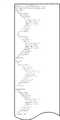
図4は、本実施例に係る画像形成装置のファームウェア更新に伴う一連の処理の一例を示すフローチャートである。図4記載の各ステップの処理は、MFP1のメインコントローラ100のフラッシュROM110、或いはHDD111に格納された制御プログラムに従ってCPU1(108)により実行される。なお、後述する図5及び図10記載の各ステップの処理も同様に、MFP1のメインコントローラ100のフラッシュROM110、或いはHDD111に格納された制御プログラムに従ってCPU1(108)により実行されるものとする。Next, a series of processes accompanying firmware update of the image forming apparatus according to the present embodiment will be described with reference to FIGS.
FIG. 4 is a flowchart illustrating an example of a series of processes associated with firmware update of the image forming apparatus according to the present exemplary embodiment. 4 is executed by the CPU 1 (108) in accordance with a control program stored in the
配信サーバ3から送信された更新ファームウェアを受信すると、CPU1(108)は、MFP1への新たなジョブの受け付けを中止し(S401)、S402に処理を進める。 When the updated firmware transmitted from the distribution server 3 is received, the CPU 1 (108) stops accepting a new job to the MFP 1 (S401), and advances the process to S402.
S402では、CPU1(108)は、現在実行中のジョブが存在するか否かを判定し(S402)、現在実行中のジョブが存在すると判定した場合(S402でNo)、現在実行中のジョブが終了するのを待つ。 In S402, the CPU 1 (108) determines whether or not there is a job that is currently being executed (S402). If it is determined that there is a job that is currently being executed (No in S402), the currently executing job is Wait for it to finish.
そして、実行中のジョブが無いと判定した場合(S402でYes)、CPU1(108)は、S403に処理を進める。
S403では、CPU1(108)は、MFP1をファームウェア更新が可能な動作モード(メンテナンスモード)に切り替えるために、システム全体の再起動を実行し、アップデート制御モジュール302を起動する。これにより、MFP1がメンテナンスモードに移行する。If it is determined that there is no job being executed (Yes in S402), the CPU 1 (108) advances the process to S403.
In step S <b> 403, the CPU 1 (108) executes restart of the entire system and activates the
次に、S404において、CPU1(108)は、ファームウェア更新前(直前)の装置状態における機器設定情報を全て読み出し(取得し)、フラッシュROM110或いはHDD111に、XML形式(一例を図6(b)に示す)で保存する(第1の取得処理)。なお、MFP1の機器設定項目は、大項目・中項目・小項目と親子関係をもったツリー構造を構成しているものとする。また、設定値としては、両面印刷のON/OFFなどの印刷処理のデフォルトの設定を示す設定値、MFP1の各種動作仕様に係る設定値などが例として考えられる。 Next, in S404, the CPU 1 (108) reads (acquires) all device setting information in the device state before the firmware update (immediately before), and stores it in the
図6(a)は、ファームウェア更新前の状態におけるMFP1の機器設定の一例を示す図である。
また、図6(b)は、図6(a)で示したファームウェア更新前の状態におけるMFP1の機器設定のリストをXML形式にした例を示す。なお、以降の説明では、このファームウェア更新前の設定値リストを第1の設定値リスト(第1の設定情報)として参照することにする。FIG. 6A is a diagram illustrating an example of device settings of the
FIG. 6B shows an example in which the device setting list of the
以下、図4の説明に戻る。
次に、S405において、CPU1(108)は、MFP1のファームウェアの更新処理を実行する。そして、ファームウェアの更新処理が完了すると、CPU1(108)は、更新処理が正常終了したか否かの判定を行う(S406)。Returning to the description of FIG.
In step S <b> 405, the CPU 1 (108) executes a firmware update process for the
そして、前記S406において、ファームウェアの更新処理が正常終了しなかったと判定した場合(No)、CPU1(108)は、S413に処理を進める。
S413では、CPU1(108)は、更新失敗としてファームウェア更新履歴を作成し、S414において、LCD104にサービスコールエラーを表示して、ファームウェア更新に伴う一連の処理を終了する。If it is determined in S406 that the firmware update process did not end normally (No), the CPU 1 (108) advances the process to S413.
In S413, the CPU 1 (108) creates a firmware update history as an update failure. In S414, the CPU 1 (108) displays a service call error on the
一方、S406において、ファームウェアの更新処理が正常終了したと判定した場合(Yes)、CPU1(108)は、S407に処理を進める。
S407では、CPU1(108)は、更新後のファームウェアに合わせて機器設定DB308の再構築を行う。さらに、S408において、CPU1(108)は、ファームウェア更新後(直後)の装置状態におけるMFP1の機器設定を全て読み出し(取得し)、フラッシュROM110或いはHDD111にXML形式(一例を図7(b)に示す)で保存する(第2の取得処理)。On the other hand, if it is determined in S406 that the firmware update process has been completed normally (Yes), the CPU 1 (108) advances the process to S407.
In S407, the CPU 1 (108) reconstructs the
図7(a)は、ファームウェア更新後の状態におけるMFP1の機器設定の一例を示す図である。
また、図7(b)は、図7(a)で示したファームウェア更新後の状態におけるMFP1の機器設定のリストをXML形式にした例を示す。なお、以降の説明では、このファームウェア更新後の設定値リストを第2の設定値リスト(第2の設定情報)として参照することにする。FIG. 7A is a diagram illustrating an example of device settings of the
FIG. 7B shows an example in which the device setting list of the
以下、図4の説明に戻る。
次に、S409において、CPU1(108)は、上述の第1の設定値リスト及び第2の設定値リストをもとにして、ファームウェア更新前後におけるMFP1の機器設定の差分(ファームウェアの更新処理によって発生したMFP1に設定された設定値の変更に関する情報)を抽出して、XML形式(一例を図8に示す)でフラッシュROM110或いはHDD111にファイル保存する(抽出処理)。なお、ここでの差分情報には、ファームウェア更新により追加または削除された機器設定、およびファームウェア更新により設定値が変更された機器設定が含まれる。また、それぞれの設定項目に対応した設定画面をLCDパネル104に表示させるための識別子(画面ID、ボタンID)の情報も設定項目毎に保存される。なお、機器設定の差分抽出方法については後述する図5で詳細に説明する。Returning to the description of FIG.
In step S <b> 409, the CPU 1 (108), based on the first setting value list and the second setting value list described above, determines the difference in device settings of the
図8は、ファームウェア更新前後における機器設定の差分情報(XML形式)の例を示す図である。
図8において、タグ「add_settings」で囲われた情報は、ファームウェア更新により追加された機器設定を示す。また、タグ「del_settings」で囲われた情報は、ファームウェア更新により削除された機器設定を示す。また、タグ「changed_settings」で囲われた情報は、ファームウェア更新により設定値が変更された機器設定を示すものとする。FIG. 8 is a diagram illustrating an example of device setting difference information (XML format) before and after firmware update.
In FIG. 8, information enclosed by a tag “add_settings” indicates a device setting added by firmware update. The information enclosed by the tag “del_settings” indicates the device setting deleted by the firmware update. The information enclosed by the tag “changed_settings” indicates the device setting whose setting value has been changed by firmware update.
また、タグ「prev_value」はファームウェア更新前の設定値を示し、タグ「crnt_value」はファームウェア更新後の設定値を示す。また、タグ「disp_id」及び「button_id」は、ファームウェア更新後のMFP1において該設定項目の設定登録画面を表示させるための識別子(画面ID、ボタンID)を示すものとする。 The tag “prev_value” indicates a set value before firmware update, and the tag “crnt_value” indicates a set value after firmware update. The tags “disp_id” and “button_id” indicate identifiers (screen ID, button ID) for displaying the setting registration screen of the setting item in the
以下、図4の説明に戻る。
次に、S410において、CPU1(108)は、更新成功としてファームウェア更新履歴を作成しファームウェア更新履歴DB309へ保存する。
図9は、ファームウェア更新履歴のデータ要素の一例を示す図である。
図9に示すように、ファームウェア更新履歴には、履歴識別番号(履歴ID)901、更新日時902、更新前のファームウェアバージョン903、更新後のファームウェアバージョン904、更新結果905、更新に伴う機器設定差分情報ファイル名(更新が正常終了した場合のみ)906などが含まれている。ここで、機器設定差分情報ファイル名906は、上述のS409で抽出保存した機器設定差分情報ファイルを指す。Returning to the description of FIG.
Next, in S <b> 410, the CPU 1 (108) creates a firmware update history as a successful update and stores it in the firmware
FIG. 9 is a diagram illustrating an example of data elements of the firmware update history.
As shown in FIG. 9, the firmware update history includes a history identification number (history ID) 901, an update date and
ここで作成したファームウェア更新履歴は、ユーザが操作ボタン或いはタッチパネル103を操作することで、LCD104上で参照することが可能になっている。ファームウェア更新履歴の参照方法については後で詳細を説明する。 The firmware update history created here can be referred to on the
以下、図4の説明に戻る。
次に、S411において、CPU1(108)は、上述のS404及びS408で作成した第1の設定値リスト及び第2の設定値リストを消去する。
次に、S412において、CPU1(108)は、MFP1を通常の動作モードに切り替えるために、通常モードでシステム全体の再起動を実行して、ファームウェア更新に伴う一連の処理を終了する。Returning to the description of FIG.
Next, in S411, the CPU 1 (108) deletes the first setting value list and the second setting value list created in S404 and S408 described above.
In step S412, the CPU 1 (108) executes a restart of the entire system in the normal mode in order to switch the
図5は、図4のS409で説明したファームウェア更新前後における機器設定差分抽出処理を説明するフローチャートである。
先ず、CPU1(108)は、S501において、第1の機器設定抽出処理を実行し、ファームウェア更新により追加された機器設定を抽出する。具体的には、CPU1(108)は、ファームウェア更新前の機器設定状態を示す第1の設定値リスト(例えば、図6(a))とファームウェア更新後の機器設定状態を示す第2の設定値リスト(例えば、図7(a))を比較し、第2の設定値リストのみに含まれる機器設定を抽出する(追加分抽出処理)。例えば、図8のタグ「add_settings」で囲われた部分の情報を抽出する。FIG. 5 is a flowchart for explaining device setting difference extraction processing before and after the firmware update described in S409 of FIG.
First, in step S <b> 501, the CPU 1 (108) executes a first device setting extraction process, and extracts a device setting added by firmware update. Specifically, the CPU 1 (108) displays a first setting value list (for example, FIG. 6A) indicating the device setting state before the firmware update and a second setting value indicating the device setting state after the firmware update. Lists (for example, FIG. 7A) are compared, and device settings included only in the second set value list are extracted (additional part extraction processing). For example, the information of the part enclosed by the tag “add_settings” in FIG. 8 is extracted.
次に、CPU1(108)は、S502において、第2の機器設定抽出処理を実行し、ファームウェア更新により削除された機器設定を抽出する。具体的には、CPU1(108)は、前記S501と同様に、第1の設定値リストと第2の設定値リストを比較し、第1の設定値リストのみに含まれる機器設定を抽出する(削除分抽出処理)。例えば、図8のタグ「del_settings」で囲われた部分の情報を抽出する。 Next, in step S <b> 502, the CPU 1 (108) executes a second device setting extraction process, and extracts device settings deleted by firmware update. Specifically, the CPU 1 (108) compares the first set value list with the second set value list and extracts the device settings included only in the first set value list, as in S501. Deleted portion extraction process). For example, information of a portion surrounded by a tag “del_settings” in FIG. 8 is extracted.
次に、CPU1(108)は、S503において、第3の機器設定抽出処理を実行し、ファームウェア更新により設定値が変更された機器設定を抽出する。具体的には、CPU1(108)は、上述のS501、S502と同様に、第1の設定値リストと第2の設定値リストを比較し、双方のリストに含まれ、且つ、設定値が異なる機器設定を抽出する(設定変更分抽出処理)。例えば、図8のタグ「changed_settings」で囲われた部分の情報を抽出する。 Next, in step S503, the CPU 1 (108) executes a third device setting extraction process, and extracts a device setting whose setting value has been changed by firmware update. Specifically, the CPU 1 (108) compares the first set value list and the second set value list as in S501 and S502 described above, and is included in both lists and the set values are different. Device settings are extracted (setting change extraction processing). For example, the information of the part enclosed by the tag “changed_settings” in FIG. 8 is extracted.
以上、ここまでに説明した処理により、MFP1のファームウェア更新に伴う機器設定の差分抽出、及び、抽出した機器設定差分情報のファームウェア更新履歴への紐付けが可能となる。 As described above, by the processing described so far, it is possible to extract a difference between device settings accompanying firmware update of the
次に、図10〜図13を用いて、本実施例に係る画像形成装置におけるファームウェア更新に伴う機器設定差分情報の参照手順について説明する。
図10は、本実施例に係る画像形成装置におけるファームウェア更新に伴う機器設定差分情報の参照手順の一例を示すフローチャートである。
MFP1の操作ボタン、或いはタッチパネル103を介してオペレータによるファームウェア更新履歴の表示指示があった場合、CPU1(108)は、本フローチャートの処理を開始する。Next, referring to FIGS. 10 to 13, a procedure for referring to device setting difference information accompanying firmware update in the image forming apparatus according to the present embodiment will be described.
FIG. 10 is a flowchart illustrating an example of a procedure for referring to device setting difference information associated with firmware update in the image forming apparatus according to the present embodiment.
When the operator gives an instruction to display the firmware update history via the operation button of the
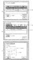
S1001において、CPU1(108)は、ファームウェア更新履歴DB309に保存されているファームウェア更新履歴(図9)を読み出して、図11(a)のように、ファームウェア更新履歴一覧をLCD104に表示する(S1001)。 In S1001, the CPU 1 (108) reads the firmware update history (FIG. 9) stored in the firmware
図11(a)は、MFP1におけるファームウェア更新履歴画面の一例を示す図である。CPU1(108)は、このファームウェア更新履歴画面からユーザからの指示を受け付けるように制御する。 FIG. 11A is a diagram illustrating an example of a firmware update history screen in the
図11(a)に示すように、表示エリア1101には、これまでにMFP1に対して実施したファームウェアの更新に対する履歴の一覧が表示されている。
ここで、オペレータが任意の履歴を選択し、設定差分情報ボタン1102を押下して設定差分情報の表示を指示すると、CPU1(108)は、この設定差分情報表示指示を検知し(S1002)、S1003に処理を進める。As shown in FIG. 11A, the
Here, when the operator selects an arbitrary history and presses the setting
S1003では、CPU1(108)は、前記S1002で選択された特定の履歴に紐付いた機器設定差分情報(図9の906により紐付いた設定値差分情報ファイル)を読み出し、図11(b)のように、設定差分情報をLCD104に表示する(S1004)。 In S1003, the CPU 1 (108) reads out the device setting difference information (setting value difference information file linked by 906 in FIG. 9) linked to the specific history selected in S1002, as shown in FIG. 11B. Then, the setting difference information is displayed on the LCD 104 (S1004).
図11(b)は、MFP1における設定差分情報画面の一例を示す図である。CPU1(108)は、この設定差分情報画面からユーザからの指示を受け付けるように制御する。 FIG. 11B is a diagram illustrating an example of the setting difference information screen in the
図11(b)において、1103は表示する差分分類を切り替えるタブであり、ファームウェア更新により追加された機器設定、削除された機器設定、および設定値が変更された機器設定のいずれかを選択して表示させることができる。即ち、図11(b)は、MFP1の設定項目を、ファームウェアの更新によって追加された設定項目、ファームウェアの更新によって削除された設定項目、ファームウェアの更新によって設定値が変更された設定項目のいずれであるかを区別可能に表示する。この図11(b)の表示により、図11(a)で選択した更新履歴に対応するファームウェアの更新により差分が生じたMFP1の設定項目(追加された設定項目、削除された設定項目、設定値が変更された設定項目)が確認可能となる。
ユーザが何らかの設定値の変更に気付いたとしても、MFP1の仕様に詳しくないユーザであればどのように設定値を変更すればいいのかわからない場合がある。このとき、例えば一週間前はMFP1がユーザの意図通りに動作していたことがわかっていれば、一週間前、もしくはその前後のファームウェアの更新履歴を確認することで、ユーザの意図通りに動作していた頃の設定値を確認することができる。In FIG. 11B,
Even if the user notices a change in some setting value, if the user is not familiar with the specifications of the
表示エリア1104には、タブ1103で選択された差分分類に該当する機器設定の一覧が表示される。図11(b)では例として、ファームウェア更新により「追加された機器設定」の一覧を表示している。 In the
ここで、オペレータが表示エリア1104から任意の機器設定を選択し、設定差分詳細情報ボタン1105を押下して設定差分詳細情報の表示を指示すると、CPU1(108)は、この設定差分詳細情報表示指示を検知し(S1005)、S1006に処理を進める。 Here, when the operator selects an arbitrary device setting from the
S1006では、CPU1(108)は、前記S1005で選択された機器設定差分情報からファームウェア更新前後の設定値を読み込み、図11(c)のように、該機器設定に関する設定差分詳細情報画面を、LCD104に表示する(S1007)。 In S1006, the CPU 1 (108) reads the setting values before and after the firmware update from the device setting difference information selected in S1005, and displays the setting difference detailed information screen related to the device setting as shown in FIG. (S1007).
図11(c)は、MFP1における設定差分詳細情報画面の一例を示す図である。CPU1(108)は、この設定差分詳細情報画面からユーザからの指示を受け付けるように制御する。 FIG. 11C is a diagram illustrating an example of the setting difference detailed information screen in the
図11(c)において、表示エリア1106には、ファームウェア更新前、および更新後それぞれの状態における該機器設定の設定値が表示される。この図11(c)の表示により、図11(a)で選択した更新履歴に対応するファームウェアの更新により差分が生じたMFP1の設定項目のうち、図11(b)で選択した設定項目の設定値が確認可能となる。
図11(c)では例として、ファームウェア更新により追加された機器設定に関する詳細情報を表示している。また、図11(c)において、設定値確認ボタン1107は、該機器設定に対する設定登録画面へのショートカットボタンとなっている。In FIG. 11C, the
In FIG. 11C, as an example, detailed information regarding the device setting added by the firmware update is displayed. In FIG. 11C, a setting
ここで、オペレータが設定値確認ボタン1107を押下して設定値の確認を指示すると、CPU1(108)は、この設定値確認指示を検知し(S1008)、S1009に処理を進める。 When the operator depresses the set
S1009では、CPU1(108)は、図11(c)の設定差分詳細情報画面で表示されている機器設定(即ち、前記1005で選択された機器設定)に対する設定登録画面の識別情報を用いて、図13(a)のように、設定登録画面を表示する(S1009)。ここで、オペレータは、現在設定されている設定値の確認、および設定の変更を行うことが可能である。 In step S1009, the CPU 1 (108) uses the identification information on the setting registration screen for the device setting (that is, the device setting selected in 1005) displayed on the setting difference detailed information screen in FIG. As shown in FIG. 13A, a setting registration screen is displayed (S1009). Here, the operator can check the setting value currently set and change the setting.
図13(a)は、MFP1における設定値確認変更画面の一例を示す図である。CPU1(108)は、この設定値確認変更画面からユーザからの指示を受け付けるように制御する。
図13(a)において、表示エリア1108には、該機器設定の設定値を設定するためのコントロールが表示される。図13(a)では例として、「PrintSettingB」の設定値を選択するためのラジオボタンが表示されている。
ここで、オペレータが表示エリア1108で設置値を選択してOKボタン1109を押下して設定値の適用を指示すると、CPU1(108)は、この設定値適用指示を検知し、該機器設定の設定値を変更する。
また、オペレータがキャンセルボタン1110を押下すると、CPU1(108)は、該機器設定の設定値を変更することなく、設定値確認変更画面を終了する。FIG. 13A is a diagram illustrating an example of a setting value confirmation change screen in the
In FIG. 13A, a
When the operator selects an installation value in the
When the operator presses the cancel
図12(a)は、MFP1における設定差分情報画面の他の例を示す図である。図12(a)は、上述の図11(b)に示す設定差分情報画面において、タブ1103で「設定値が変更された機器設定」が選択され、ファームウェア更新により「設定値が変更された機器設定」の表示指示があった場合の画面表示の例に対応する。なお、図11(b)と同一のものには同一の符号を付してある。 FIG. 12A is a diagram illustrating another example of the setting difference information screen in the
また、図12(b)は、MFP1における設定差分詳細情報画面の他の例を示す図である。図12(b)は、図12(a)の表示画面において、設定差分詳細情報ボタン1105が押下された場合に表示される設定差分詳細情報画面の例に対応する。なお、図11(c)と同一のものには同一の符号を付してある。
この場合も、設定値確認ボタン1107を押下することで、該機器設定に対する設定登録画面(図13(b))が表示され、現在設定されている設定値の確認、および設定の変更を行うことが可能である。FIG. 12B shows another example of the setting difference detailed information screen in the
Also in this case, by pressing the set
図13(b)は、MFP1における設定値確認変更画面の他の例を示す図である。図13(b)は、図12(b)の表示画面において、設定値確認ボタン1107が押下された場合に表示される設定値確認変更画面の例に対応する。なお、図13(a)と同一のものには同一の符号を付してある。
この場合、オペレータが表示エリア1108で、「Copy Setting A」の設置値を選択して、OKボタン1109を押下して設定値の適用を指示すると、CPU1(108)は、この設定値適用指示を検知し、「Copy Setting A」の設定値を変更する。FIG. 13B is a diagram illustrating another example of the setting value confirmation change screen in the
In this case, when the operator selects the setting value of “Copy Setting A” in the
以上詳細に説明したように、本実施例によれば、画像形成装置は、ファームウェアの更新に伴い更新前後の画像形成装置の機器設定に差分が生じた場合であっても、自動で(ユーザの意図的な操作なしに)差分を抽出して、ファームウェア更新履歴に紐付けて保存することができる。このため、ユーザは、操作部よりファームウェアの更新履歴を起点として、該更新に係る機器設定の差分の詳細情報を確認することが可能となる。 As described above in detail, according to the present embodiment, the image forming apparatus automatically (when the user changes the device settings of the image forming apparatus before and after the update) Differences can be extracted (without intentional operation) and stored in association with the firmware update history. For this reason, the user can check the detailed information of the difference in the device settings related to the update from the firmware update history as the starting point from the operation unit.
さらに、詳細情報の確認画面に設けられる、差分が生じた機器設定それぞれの設定登録画面の識別情報を用いて(タッチして)、該機器設定に対応する設定登録画面を操作部に表示させることが可能である。このため、ユーザはその機器設定の設定登録画面を、わざわざ機器設定項目のトップ画面から大項目・中項目・小項目と親子関係たどって開いて、その機器設定を確認するといった煩雑な操作を行う必要がなく、短い手順で(例えば、図11(c)の1007をタッチするだけで)設定値確認変更画面を表示でき、現在設定されている設定値の確認、および設定の変更を容易に行うことができる。
従って、ファームウェアの更新に伴って画像形成装置の機器設定に生じた差分の確認や設定値の変更についての操作性を大幅に向上することができる。Furthermore, using the identification information on the setting registration screen of each device setting in which the difference has been provided provided on the detailed information confirmation screen, the setting registration screen corresponding to the device setting is displayed on the operation unit. Is possible. For this reason, the user performs troublesome operations such as opening the setting registration screen for the device setting from the top screen of the device setting item by following the parent / child relationship with the large item / medium item / small item and checking the device setting. There is no need, and the setting value confirmation / change screen can be displayed in a short procedure (for example, by simply touching 1007 in FIG. 11C), and it is easy to check the setting value currently set and change the setting. be able to.
Therefore, it is possible to greatly improve the operability for checking the difference that has occurred in the device settings of the image forming apparatus and changing the setting value due to the firmware update.
なお、上述した各種データの構成及びその内容はこれに限定されるものではなく、用途や目的に応じて、様々な構成や内容で構成されることは言うまでもない。
以上、一実施形態について示したが、本発明は、例えば、システム、装置、方法、プログラムもしくは記憶媒体等としての実施態様をとることが可能である。具体的には、複数の機器から構成されるシステムに適用しても良いし、また、一つの機器からなる装置に適用しても良い。
また、上記各実施例を組み合わせた構成も全て本発明に含まれるものである。It should be noted that the configuration and contents of the various data described above are not limited to this, and it goes without saying that the various data and configurations are configured according to the application and purpose.
Although one embodiment has been described above, the present invention can take an embodiment as, for example, a system, apparatus, method, program, or storage medium. Specifically, the present invention may be applied to a system composed of a plurality of devices, or may be applied to an apparatus composed of a single device.
Moreover, all the structures which combined said each Example are also contained in this invention.
(他の実施例)
また、本発明は、以下の処理を実行することによっても実現される。即ち、上述した実施形態の機能を実現するソフトウェア(プログラム)を、ネットワーク又は各種記憶媒体を介してシステム或いは装置に供給し、そのシステム或いは装置のコンピュータ(またはCPUやMPU等)がプログラムを読み出して実行する処理である。(Other examples)
The present invention can also be realized by executing the following processing. That is, software (program) that realizes the functions of the above-described embodiments is supplied to a system or apparatus via a network or various storage media, and a computer (or CPU, MPU, or the like) of the system or apparatus reads the program. It is a process to be executed.
また、本発明は、複数の機器から構成されるシステムに適用しても、1つの機器からなる装置に適用してもよい。
本発明は上記実施例に限定されるものではなく、本発明の趣旨に基づき種々の変形(各実施例の有機的な組合せを含む)が可能であり、それらを本発明の範囲から除外するものではない。即ち、上述した各実施例及びその変形例を組み合わせた構成も全て本発明に含まれるものである。Further, the present invention may be applied to a system composed of a plurality of devices or an apparatus composed of a single device.
The present invention is not limited to the above embodiments, and various modifications (including organic combinations of the embodiments) are possible based on the spirit of the present invention, and these are excluded from the scope of the present invention. is not. That is, the present invention includes all the combinations of the above-described embodiments and modifications thereof.
108 CPU1
109 RAM1
110 フラッシュROM
111 HDD
301 ネットワーク制御モジュール
302 アップデート制御モジュール
303 機器設定エクスポートモジュール
304 機器設定差分抽出モジュール
305 機器設定管理モジュール
306 ファームウェア更新履歴管理モジュール
307 DBMSモジュール
308 機器設定DB
309 ファームウェア更新履歴DB
310 UI制御モジュール108 CPU1
109 RAM1
110 Flash ROM
111 HDD
301
309 Firmware update history DB
310 UI control module
Claims (7)
Translated fromJapanese前記画像形成装置のファームェアを更新するための更新処理を実行する更新手段と、
前記更新手段が前記更新処理を実行した場合に、前記更新処理によって追加された設定項目と、前記更新処理によって削除された設定項目と、前記更新処理によって変更された設定項目の変更前の設定値と、前記更新処理によって変更された設定項目の変更後の設定値とを示す設定差分情報を生成する生成手段と、
前記生成手段によって生成された前記設定差分情報を更新履歴に対応付けて蓄積する蓄積手段と、
前記更新処理に関する更新履歴画面を表示する表示手段と、を備え、
前記更新履歴画面において複数の更新履歴の中から特定の更新履歴をユーザが選択した場合に、前記表示手段は、前記特定の更新履歴に対応する前記設定差分情報に基づいて、前記特定の更新履歴が示す更新処理によって追加された設定項目と、前記特定の更新履歴が示す更新処理によって削除された設定項目と、前記特定の更新履歴が示す更新処理によって変更された設定項目の変更前の設定値と、前記特定の更新履歴が示す更新処理によって変更された設定項目の変更後の設定値とを表示することを特徴とする画像形成装置。An image forming apparatus capable of executing printing,
Update means for executing update processing for updating the firmware of the image forming apparatus;
When the update unit executes the update process, the setting item added by the update process, the setting item deleted by the update process, and the setting value before the change of the setting item changed by the update process Generating means for generating setting difference information indicating the setting value after the change of the setting item changed by the update process;
Storage means for storing the setting difference information generated by the generation means in association with an update history;
Display means for displaying an update history screen relating to the update process,
When the user selects a specific update history from a plurality of update histories on the update history screen, the display unit is configured to display the specific update history based on the setting difference information corresponding to the specific update history. The setting item added by the update process indicated by, the setting item deleted by the update process indicated by the specific update history, and the setting value before the change of the setting item changed by the update process indicated by the specific update history And an updated setting value of the setting item changed by the update process indicated by the specific update history.
前記生成手段は、前記更新処理が正常に終了したと前記判定手段によって判定された場合に、前記設定差分情報を生成することを特徴とする請求項1又は2に記載の画像形成装置。A determination unit for determining whether or not the update process has been normally completed;
The image forming apparatus according to claim 1, wherein the generation unit generates the setting difference information when the determination unit determines that the update process has been normally completed.
前記画像形成装置のファームェアを更新するための更新処理を実行する更新ステップと、
前記更新ステップで前記更新処理が実行された場合に、前記更新処理によって追加された設定項目と、前記更新処理によって削除された設定項目と、前記更新処理によって変更された設定項目の変更前の設定値と、前記更新処理によって変更された設定項目の変更後の設定値とを示す設定差分情報を生成する生成ステップと、
前記生成ステップによって生成された前記設定差分情報を更新履歴に対応付けて蓄積する蓄積ステップと、
前記更新処理に関する更新履歴画面を表示する表示ステップと、を備え、
前記表示ステップでは、前記更新履歴画面において複数の更新履歴の中から特定の更新履歴をユーザが選択した場合に、前記特定の更新履歴に対応する前記設定差分情報に基づいて、前記特定の更新履歴が示す更新処理によって追加された設定項目と、前記特定の更新履歴が示す更新処理によって削除された設定項目と、前記特定の更新履歴が示す更新処理によって変更された設定項目の変更前の設定値と、前記特定の更新履歴が示す更新処理によって変更された設定項目の変更後の設定値とを表示することを特徴とする画像形成装置の制御方法。A control method for an image forming apparatus capable of executing printing,
An update step for executing an update process for updating the firmware of the image forming apparatus;
When the update process is executed in the update step, the setting item added by the update process, the setting item deleted by the update process, and the setting before the change of the setting item changed by the update process Generating step for generating setting difference information indicating a value and a setting value after the change of the setting item changed by the update process;
An accumulation step of accumulating the setting difference information generated by the generation step in association with an update history;
A display step for displaying an update history screen relating to the update process,
In the display step, when a user selects a specific update history from a plurality of update histories on the update history screen, the specific update history is based on the setting difference information corresponding to the specific update history. The setting item added by the update process indicated by, the setting item deleted by the update process indicated by the specific update history, and the setting value before the change of the setting item changed by the update process indicated by the specific update history And a setting value after the change of the setting item changed by the update process indicated by the specific update history is displayed.
Priority Applications (2)
| Application Number | Priority Date | Filing Date | Title |
|---|---|---|---|
| JP2012019898AJP5843637B2 (en) | 2012-02-01 | 2012-02-01 | Image forming apparatus, image forming apparatus control method, and program |
| US13/752,869US9354680B2 (en) | 2012-02-01 | 2013-01-29 | Image forming apparatus, control method for image forming apparatus, and storage medium having a firmware update function |
Applications Claiming Priority (1)
| Application Number | Priority Date | Filing Date | Title |
|---|---|---|---|
| JP2012019898AJP5843637B2 (en) | 2012-02-01 | 2012-02-01 | Image forming apparatus, image forming apparatus control method, and program |
Publications (3)
| Publication Number | Publication Date |
|---|---|
| JP2013161117A JP2013161117A (en) | 2013-08-19 |
| JP2013161117A5 JP2013161117A5 (en) | 2015-07-02 |
| JP5843637B2true JP5843637B2 (en) | 2016-01-13 |
Family
ID=48871363
Family Applications (1)
| Application Number | Title | Priority Date | Filing Date |
|---|---|---|---|
| JP2012019898AExpired - Fee RelatedJP5843637B2 (en) | 2012-02-01 | 2012-02-01 | Image forming apparatus, image forming apparatus control method, and program |
Country Status (2)
| Country | Link |
|---|---|
| US (1) | US9354680B2 (en) |
| JP (1) | JP5843637B2 (en) |
Cited By (1)
| Publication number | Priority date | Publication date | Assignee | Title |
|---|---|---|---|---|
| EP4361799A1 (en) | 2022-10-31 | 2024-05-01 | Canon Kabushiki Kaisha | Information processing apparatus, information processing method, and storage medium |
Families Citing this family (32)
| Publication number | Priority date | Publication date | Assignee | Title |
|---|---|---|---|---|
| US10862784B2 (en) | 2011-10-04 | 2020-12-08 | Electro Industries/Gauge Tech | Systems and methods for processing meter information in a network of intelligent electronic devices |
| US12260078B2 (en) | 2011-10-04 | 2025-03-25 | Ei Electronics Llc | Dynamic webpage interface for an intelligent electronic device |
| US20150356104A9 (en) | 2011-10-04 | 2015-12-10 | Electro Industries/Gauge Tech | Systems and methods for collecting, analyzing, billing, and reporting data from intelligent electronic devices |
| US10275840B2 (en) | 2011-10-04 | 2019-04-30 | Electro Industries/Gauge Tech | Systems and methods for collecting, analyzing, billing, and reporting data from intelligent electronic devices |
| JP6128388B2 (en)* | 2012-09-14 | 2017-05-17 | パナソニックIpマネジメント株式会社 | Information processing device |
| JP2014127783A (en)* | 2012-12-26 | 2014-07-07 | Canon Inc | Management system for information processor, information processor, control method for information processor and program |
| KR101992680B1 (en)* | 2013-02-05 | 2019-06-25 | 휴렛-팩커드 디벨롭먼트 컴퍼니, 엘.피. | Image forming apparatus, tracking apparatus, managing apparatus and method for updating firmware of image forming apparatus |
| US11816465B2 (en)* | 2013-03-15 | 2023-11-14 | Ei Electronics Llc | Devices, systems and methods for tracking and upgrading firmware in intelligent electronic devices |
| JP2015056078A (en)* | 2013-09-12 | 2015-03-23 | 株式会社リコー | Information processing system, information processing method, and program |
| US11734396B2 (en) | 2014-06-17 | 2023-08-22 | El Electronics Llc | Security through layers in an intelligent electronic device |
| WO2016125455A1 (en)* | 2015-02-05 | 2016-08-11 | 日本電気株式会社 | Communication system, communication device, and communication method |
| US10958435B2 (en) | 2015-12-21 | 2021-03-23 | Electro Industries/ Gauge Tech | Providing security in an intelligent electronic device |
| JP6659150B2 (en)* | 2016-02-05 | 2020-03-04 | キヤノン株式会社 | DEVICE, ITS CONTROL METHOD, AND PROGRAM |
| JP6661409B2 (en)* | 2016-03-01 | 2020-03-11 | キヤノン株式会社 | Automatic installation system, information processing apparatus, information processing apparatus control method, and program |
| JP6892236B2 (en)* | 2016-10-05 | 2021-06-23 | 株式会社東芝 | Maintenance terminal, data installation method, and data installation program |
| JP6904135B2 (en)* | 2017-07-26 | 2021-07-14 | 京セラドキュメントソリューションズ株式会社 | Electronic device and setting value change program |
| US10552145B2 (en)* | 2017-12-12 | 2020-02-04 | Cypress Semiconductor Corporation | Memory devices, systems, and methods for updating firmware with single memory device |
| US11537389B2 (en) | 2017-12-12 | 2022-12-27 | Infineon Technologies LLC | Memory devices, systems, and methods for updating firmware with single memory device |
| US20190236279A1 (en)* | 2018-01-31 | 2019-08-01 | Hewlett Packard Enterprise Development Lp | Perform security action based on inventory comparison |
| US11734704B2 (en) | 2018-02-17 | 2023-08-22 | Ei Electronics Llc | Devices, systems and methods for the collection of meter data in a common, globally accessible, group of servers, to provide simpler configuration, collection, viewing, and analysis of the meter data |
| US11686594B2 (en) | 2018-02-17 | 2023-06-27 | Ei Electronics Llc | Devices, systems and methods for a cloud-based meter management system |
| US11754997B2 (en) | 2018-02-17 | 2023-09-12 | Ei Electronics Llc | Devices, systems and methods for predicting future consumption values of load(s) in power distribution systems |
| JP7011373B2 (en)* | 2018-07-11 | 2022-01-26 | キヤノン株式会社 | Multifunction device and its control method, and program |
| JP7102269B2 (en)* | 2018-07-11 | 2022-07-19 | キヤノン株式会社 | Image processing device, control method of image processing device, and program |
| US12288058B2 (en) | 2018-09-20 | 2025-04-29 | Ei Electronics Llc | Devices, systems and methods for tracking and upgrading firmware in intelligent electronic devices |
| JP7196556B2 (en)* | 2018-11-20 | 2022-12-27 | コニカミノルタ株式会社 | Image forming device, information processing device and program |
| US11863589B2 (en) | 2019-06-07 | 2024-01-02 | Ei Electronics Llc | Enterprise security in meters |
| JP7408931B2 (en)* | 2019-06-28 | 2024-01-09 | 株式会社リコー | Electronic equipment, information processing systems, information processing methods and programs |
| US20220291738A1 (en)* | 2021-03-10 | 2022-09-15 | Xerox Corporation | Methods and systems for automatically saving power during an upgrade of a device |
| KR102510167B1 (en)* | 2021-08-03 | 2023-03-15 | 시큐리티플랫폼 주식회사 | Firmware massive update method using flash memory and computer programs stored in recording media for executing the same |
| US12373544B2 (en)* | 2022-02-04 | 2025-07-29 | Toshiba Tec Kabushiki Kaisha | Information processing apparatus, image formation apparatus, and information processing method |
| JP2023157629A (en)* | 2022-04-15 | 2023-10-26 | 株式会社リコー | Information processing device, firmware update method, image forming device |
Family Cites Families (16)
| Publication number | Priority date | Publication date | Assignee | Title |
|---|---|---|---|---|
| JP3876607B2 (en)* | 2000-10-24 | 2007-02-07 | 松下電工株式会社 | Parameter setting method in image processing system |
| JP4258312B2 (en) | 2003-07-28 | 2009-04-30 | 富士ゼロックス株式会社 | Image forming apparatus and program update history management method thereof |
| JP4021407B2 (en)* | 2003-12-16 | 2007-12-12 | シャープ株式会社 | Information processing device |
| US20080005733A1 (en)* | 2006-06-29 | 2008-01-03 | Balaji Ramachandran | Method and apparatus for updating firmware and software |
| JP5012017B2 (en)* | 2006-12-28 | 2012-08-29 | 富士通株式会社 | Embedded device and control method |
| JP2008200934A (en)* | 2007-02-19 | 2008-09-04 | Murata Mach Ltd | Image forming apparatus |
| JP4329843B2 (en)* | 2007-05-28 | 2009-09-09 | 船井電機株式会社 | Receiver |
| KR101448994B1 (en)* | 2007-06-12 | 2014-10-08 | 엘지전자 주식회사 | Video display device with firmware download history management function and control method |
| US20080320110A1 (en)* | 2007-06-25 | 2008-12-25 | Sharp Laboratories Of America, Inc. | Firmware rollback and configuration restoration for electronic devices |
| KR101219432B1 (en)* | 2008-03-18 | 2013-01-11 | 삼성전자주식회사 | Image forming apparatus and firmware history information offering method thereof |
| JP4618358B2 (en)* | 2008-09-29 | 2011-01-26 | ブラザー工業株式会社 | Peripheral device management program and peripheral device management system |
| KR20100081720A (en)* | 2009-01-07 | 2010-07-15 | 삼성전자주식회사 | Method and system for fota service |
| JP2011016329A (en)* | 2009-07-10 | 2011-01-27 | Ricoh Co Ltd | Printer controller |
| KR20120023474A (en)* | 2010-09-03 | 2012-03-13 | 엘에스산전 주식회사 | System and method for firmware update of household appliances, and meter |
| US20120144380A1 (en)* | 2010-12-07 | 2012-06-07 | Samsung Electronics Co. Ltd. | Method for generating delta file using basic blocks |
| JP5821640B2 (en)* | 2012-01-06 | 2015-11-24 | 株式会社リコー | Information processing device |
- 2012
- 2012-02-01JPJP2012019898Apatent/JP5843637B2/ennot_activeExpired - Fee Related
- 2013
- 2013-01-29USUS13/752,869patent/US9354680B2/ennot_activeExpired - Fee Related
Cited By (1)
| Publication number | Priority date | Publication date | Assignee | Title |
|---|---|---|---|---|
| EP4361799A1 (en) | 2022-10-31 | 2024-05-01 | Canon Kabushiki Kaisha | Information processing apparatus, information processing method, and storage medium |
Also Published As
| Publication number | Publication date |
|---|---|
| US20130198507A1 (en) | 2013-08-01 |
| JP2013161117A (en) | 2013-08-19 |
| US9354680B2 (en) | 2016-05-31 |
Similar Documents
| Publication | Publication Date | Title |
|---|---|---|
| JP5843637B2 (en) | Image forming apparatus, image forming apparatus control method, and program | |
| US9036178B2 (en) | Display apparatus, method of controlling operations of the same, and network system | |
| US9459816B2 (en) | Information processing apparatus, method, computer-readable storage medium, and information processing system | |
| CN106161833B (en) | Operation screen providing system, relay device and operation screen providing method | |
| US20100058123A1 (en) | Electronic device and error management system | |
| US11778110B2 (en) | Image processing apparatus displaying a home screen in a fixed button mode in a state where acquisition of a recommended button information is unavailable | |
| US10129426B2 (en) | Image forming apparatus having display screen with position configurable icons, information processing method, and computer-readable recording medium | |
| JP5728896B2 (en) | Printing system and program | |
| JP6492711B2 (en) | Relay device, operation screen providing device, and program | |
| JP2015114395A (en) | Sheet management device, method for controlling sheet management device, program, and recording medium | |
| JP6136703B2 (en) | Information processing program and information processing apparatus | |
| US20170187889A1 (en) | Information processing apparatus, information system, information processing method, and storage medium | |
| US11902478B2 (en) | System, user device and method that enables the user to be effectively notified of a failure circumstance | |
| JP5636829B2 (en) | Customization system, image forming apparatus, information processing apparatus, and customization program | |
| US8462372B2 (en) | Image processing apparatus and image processing method for storing output pattern data according to a kind of document | |
| JP6123109B2 (en) | Image forming apparatus | |
| JP6834716B2 (en) | Print management program, print management method, print management device and print management system | |
| US9942427B2 (en) | Information processing apparatus, display control method, and storage medium | |
| JP6493119B2 (en) | Image forming system and operation device | |
| JP6591011B2 (en) | Printing system, printing apparatus, and printing apparatus control method | |
| EP3689629A1 (en) | Electronic device | |
| KR20190038188A (en) | Image forming apparatus and method for performing error recovery function thereof | |
| JP2011049828A (en) | Image forming apparatus, image formation system |
Legal Events
| Date | Code | Title | Description |
|---|---|---|---|
| A621 | Written request for application examination | Free format text:JAPANESE INTERMEDIATE CODE: A621 Effective date:20150123 | |
| A521 | Written amendment | Free format text:JAPANESE INTERMEDIATE CODE: A523 Effective date:20150515 | |
| RD03 | Notification of appointment of power of attorney | Free format text:JAPANESE INTERMEDIATE CODE: A7423 Effective date:20150615 | |
| A977 | Report on retrieval | Free format text:JAPANESE INTERMEDIATE CODE: A971007 Effective date:20150908 | |
| TRDD | Decision of grant or rejection written | ||
| A01 | Written decision to grant a patent or to grant a registration (utility model) | Free format text:JAPANESE INTERMEDIATE CODE: A01 Effective date:20151020 | |
| A61 | First payment of annual fees (during grant procedure) | Free format text:JAPANESE INTERMEDIATE CODE: A61 Effective date:20151117 | |
| LAPS | Cancellation because of no payment of annual fees |