JP5843583B2 - Wireless communication device, power transmission device, and IC card device - Google Patents
Wireless communication device, power transmission device, and IC card deviceDownload PDFInfo
- Publication number
- JP5843583B2 JP5843583B2JP2011259464AJP2011259464AJP5843583B2JP 5843583 B2JP5843583 B2JP 5843583B2JP 2011259464 AJP2011259464 AJP 2011259464AJP 2011259464 AJP2011259464 AJP 2011259464AJP 5843583 B2JP5843583 B2JP 5843583B2
- Authority
- JP
- Japan
- Prior art keywords
- wireless communication
- power
- unit
- communication unit
- signal
- Prior art date
- Legal status (The legal status is an assumption and is not a legal conclusion. Google has not performed a legal analysis and makes no representation as to the accuracy of the status listed.)
- Expired - Fee Related
Links
Images


Classifications
- H—ELECTRICITY
- H04—ELECTRIC COMMUNICATION TECHNIQUE
- H04B—TRANSMISSION
- H04B5/00—Near-field transmission systems, e.g. inductive or capacitive transmission systems
- H04B5/20—Near-field transmission systems, e.g. inductive or capacitive transmission systems characterised by the transmission technique; characterised by the transmission medium
- H04B5/24—Inductive coupling
- H04B5/26—Inductive coupling using coils
- H04B5/266—One coil at each side, e.g. with primary and secondary coils
- H—ELECTRICITY
- H04—ELECTRIC COMMUNICATION TECHNIQUE
- H04B—TRANSMISSION
- H04B5/00—Near-field transmission systems, e.g. inductive or capacitive transmission systems
- H04B5/70—Near-field transmission systems, e.g. inductive or capacitive transmission systems specially adapted for specific purposes
- H04B5/79—Near-field transmission systems, e.g. inductive or capacitive transmission systems specially adapted for specific purposes for data transfer in combination with power transfer
Landscapes
- Engineering & Computer Science (AREA)
- Computer Networks & Wireless Communication (AREA)
- Signal Processing (AREA)
- Near-Field Transmission Systems (AREA)
Description
Translated fromJapanese本発明の実施形態は、受信した電力を利用して無線通信を行う無線通信装置、電力送信装置およびICカード装置に関する。 Embodiments described herein relate generally to a wireless communication device, a power transmission device, and an IC card device that perform wireless communication using received power.
Felica(登録商標)等のNFC(Near Field Communication:近距離無線通信)では、コイルによる電磁誘導を用いた通信を行うものであり、近接無線または非接触無線と呼ばれる場合もある。以下これらを非接触無線と呼ぶこととする。非接触無線では、電磁誘導により電力が供給され、その電力を利用して無線通信を行うことが1つの特徴である。そのため、カード型装置などの装置内部からの電源供給がない装置にも適用できるという利点がある一方で、非接触無線では通信速度が遅く、大容量データを転送するのに長い時間を要するという問題がある。 In NFC (Near Field Communication) such as Felica (registered trademark), communication using electromagnetic induction by a coil is performed, which is sometimes referred to as proximity radio or non-contact radio. Hereinafter, these are referred to as non-contact radio. One characteristic of contactless radio is that electric power is supplied by electromagnetic induction and wireless communication is performed using the electric power. Therefore, there is an advantage that it can be applied to a device that does not supply power from inside the device such as a card type device, but the problem is that the communication speed is slow in contactless wireless and it takes a long time to transfer a large amount of data. There is.
この問題を解決する手法の1つとして、非接触無線と高速な無線通信を組み合わせる技術が提案されている。この技術は、非接触無線を用いて接続を行い、その後の通信を高速な無線通信を用いて行うことで、通信速度の向上を図るものである。しかしながら、高速な無線通信は一般に消費電力が大きいため、非接触無線で供給される電力では、高速な無線通信を行うのに電力不足が生じ、安定した無線通信を行えないおそれがある。 As one method for solving this problem, a technique that combines contactless radio and high-speed radio communication has been proposed. This technology is intended to improve communication speed by performing connection using non-contact wireless and performing subsequent communication using high-speed wireless communication. However, since high-speed wireless communication generally consumes a large amount of power, the power supplied by non-contact wireless may cause insufficient power to perform high-speed wireless communication, and stable wireless communication may not be performed.
本発明は、受信した電力を有効利用して、安定した高速通信を行うことができる無線通信装置、電力送信装置およびICカード装置を提供するものである。 The present invention provides a wireless communication device, a power transmission device, and an IC card device that can perform stable high-speed communication by effectively using received power.
本実施形態では、受信した電力を利用して無線通信を行う電力受信無線通信部と、
前記電力受信無線通信部で受信した電力の一部を蓄電する蓄電部と、
前記蓄電部に蓄電された電力量が第1基準量を超えた場合に、前記蓄電部に蓄電された電力の一部を利用して、前記電力受信無線通信部よりも高速かつ高効率で無線通信を行う第1無線通信部と、を備え、
前記電力受信無線通信部は、
電力を受信して、受信した電力の一部を前記蓄電部に供給する電力受信部と、
前記電力受信部で受信された電力の一部を利用して、前記第1無線通信部よりも低速かつ低効率で無線通信を行う第2無線通信部と、を有することを特徴とする無線通信装置が提供される。In the present embodiment, a power reception wireless communication unit that performs wireless communication using received power;
A power storage unit that stores a part of the power received by the power reception wireless communication unit;
When the amount of power stored in the power storage unit exceeds a first reference amount, a part of the power stored in the power storage unit is used and wirelessly faster and more efficient than the power receiving wireless communication unit A first wireless communication unit for performing communication,
The power receiving radio communication unit is
A power receiving unit that receives power and supplies a part of the received power to the power storage unit;
A second wireless communication unit that performs wireless communication at a lower speed and with lower efficiency than the first wireless communication unit by using a part of the power received by the power receiving unit. An apparatus is provided.
以下、図面を参照しながら、本発明の実施形態について説明する。 Hereinafter, embodiments of the present invention will be described with reference to the drawings.
(第1の実施形態)
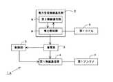
図1は第1の実施形態に係る無線通信装置1の概略構成を示すブロック図である。図1の無線通信装置1は、受信した電力を利用して無線通信を行う電力受信無線通信部2と、電力受信無線通信部2で受信した電力の一部を蓄電する蓄電部3と、蓄電部3に蓄電された電力量が第1基準量を超えた場合に蓄電部3に蓄電された電力の一部を利用して電力受信無線通信部2よりも高速かつ高効率で無線通信を行う第1無線通信部4と、蓄電部3および第1無線通信部4を制御する制御部5と、電力受信無線通信部2に接続される第1コイル6と、第1無線通信部4に接続される第1アンテナ7とを備えている。第1無線通信部4は、電力受信無線通信部2よりも高速かつ高効率で無線通信可能であればよく、電力受信無線通信部2よりも低速又は低効率の無線通信を行うことができても良い。(First embodiment)
FIG. 1 is a block diagram showing a schematic configuration of a
高速とは、データレートが大きいことを意味し、あるサイズのデータを送信するのに要する時間が短いことを意味する。高速とは、一般的には、bps(Bit Per Sec:ビットパーセック)という単位の値が大きいことである。高効率とは、通信に関わる消費電力の効率が高いことを意味し、あるサイズのデータを送信するのに要する消費電力量が小さいことを意味する。一般的には、高効率とは、J/bit(Joule per bit: ジュールパービット)という単位の値が小さいことである。 High speed means that the data rate is large, and that it takes a short time to transmit data of a certain size. High speed generally means that the unit value of bps (Bit Per Sec) is large. High efficiency means that the efficiency of power consumption related to communication is high, and means that the power consumption required to transmit data of a certain size is small. In general, high efficiency means that the unit value of J / bit (Joule per bit) is small.
電力受信無線通信部2は、電力受信部8と第2無線通信部9を有する。電力受信部8は、第1コイル6にて電磁誘導により受信した電力の一部を蓄電部3に供給する。第2無線通信部9は、電力受信部8で受信された電力の一部を利用して、第1無線通信部4よりも低速かつ低効率で無線通信を行う。 The power reception
第1無線通信部4が行う高速かつ高効率の無線通信は、ミリ波帯域の無線通信、TransferJet(登録商標)、無線LANおよびBluetooth(登録商標)などであり、具体的な無線方式は問わない。また、第2無線通信部9が行う低速かつ低効率の無線通信は、Felica等のNFCであり、第1無線通信部4よりも低速かつ低効率の無線通信を行う無線方式であれば、具体的な方式は問わない。 The high-speed and high-efficiency wireless communication performed by the first
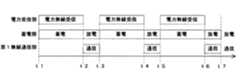
図2は図1の無線通信装置1の動作タイミング図である。図2の横軸は時間軸を表し、縦軸は無線通信装置1内で動作する各部の名称を示している。図示のように、時刻t1のときに、電力受信部8は電力の受信を開始し、それに合わせて、蓄電部3は受信電力の蓄電を開始する。時刻t2になると、蓄電部3に蓄電された電力量が第1基準量を超える。従って、第1無線通信部4は蓄電部3に蓄電された電力を利用して、高速かつ高効率の無線通信を開始する。 FIG. 2 is an operation timing chart of the
制御部5は、蓄電部3に蓄電された電力量を継続してモニターしており、いったん第1無線通信部4が無線通信を開始しても、蓄電部3に蓄電された電力量が第2基準量以下になると、第1無線通信部4の無線通信を中断させ、その後に、再度電力量が第1基準量を超えたときに、第1無線通信部4の無線通信を再開させる。したがって、第1無線通信部4は、間歇的に無線通信を行うことになる。 The
図3は図2よりも長い時間間隔での図1の無線通信装置1の動作タイミング図である。図示のように、第1無線通信部4は、蓄電部3で蓄電された電力量が第1基準量を超えている期間(t2〜t3、t4〜t5、t6〜t7)のみ、不図示の電力送信装置と無線通信を行う。これらの期間では、蓄電部3は放電処理を行い、これらの期間以外では、蓄電部3は電力受信部8で受信された電力を蓄電する充電処理を行う。放電中も継続して、電力受信部8で電力を受信し、また蓄電部3にて並行して蓄電を行ってもよい。このようにすると、より長い時間通信を継続できるという利点が得られる。 FIG. 3 is an operation timing chart of the
このように、第1の実施形態では、高速かつ高効率で無線通信を行う第1無線通信部4と、第1無線通信部4よりも低速かつ低効率で無線通信を行う第2無線通信部9と、第1コイル6にて電磁誘導で受信した電力を受信する電力受信部8と、受信した電力の一部を蓄電する蓄電部3とを備えて、蓄電部3に蓄電された電力量が第1基準量を超えた場合に限って、第1無線通信部4での無線通信を行うため、電力不足で第1無線通信部4の無線通信が不安定になるおそれはない。例えば、大容量のデータを送信する必要がある場合には、第1無線通信部4は間歇的に動作して、複数回に分けてデータ送信を行うため、大容量のデータ送信も支障なく行うことができる。 Thus, in the first embodiment, the first
すなわち、第1の実施形態では、高速かつ高効率で無線通信を行う能力を持つ第1無線通信部4に対して、十分な電力を供給できるときだけ、第1無線通信装置4を駆動するため、第1無線通信装置4の潜在能力を十分に生かして高速かつ高効率の無線通信を行うことができる。 That is, in the first embodiment, the first
また、第1の実施形態は第1無線通信部4よりも低速かつ低効率の無線通信を行う第2無線通信部9も備えており、この第2無線通信部9では、電力受信部8で受信した電力を利用して継続して無線通信を行うため、データ量の少ない低速の無線通信を継続的に行うことができ、第1無線通信部4の無線通信が中断されている間も、第2無線通信部9を介した無線通信を継続的に行うことができる。 The first embodiment also includes a second
(第2の実施形態)
第2の実施形態は、第1の実施形態のより具体的な第1例である。(Second Embodiment)
The second embodiment is a more specific first example of the first embodiment.
図4は第2の実施形態に係る無線通信装置1aの概略構成を示すブロック図である。図4の無線通信装置1aは、図1と共通する構成部分には同一の符号を付しており、以下では相違点を中心に説明する。 FIG. 4 is a block diagram showing a schematic configuration of the wireless communication device 1a according to the second embodiment. In the wireless communication device 1a of FIG. 4, the same reference numerals are given to the same components as in FIG. 1, and the differences will be mainly described below.
図4の無線通信装置1aは、電力受信無線通信部2内の電力受信部8に第1コイル6が接続されている点と、電力受信部8と第2無線通信部9が双方向に信号の送受を行う点とで、図1と異なっている。 The wireless communication device 1a of FIG. 4 is configured such that the
図4の電力受信部8は、不図示の電力送信装置から送信されたRF信号を、第1コイル6を介して受信する。また、図4の第2無線通信部9は、この第1コイル6を利用して、電力送信装置にRF信号を送信する。より詳細には、第2無線通信部9は、第1コイル6で受信されたRF信号の定包絡信号の振幅を変調して新たなRF信号を生成して、第1コイル6を介して電力送信装置に送信する。 The
電力受信部8と第2無線通信部9は、第1コイル6を用いた電磁誘導で電力送信装置と無線通信を行うため、図4の無線通信装置1aと電力送信装置は近接した距離に置かれた場合のみ無線通信が可能となる。したがって、無線通信装置1aと電力送信装置との無線通信は、例えばNFCのような電磁誘導を利用した通信を行うことを想定している。 Since the
このように、第2の実施形態は、電力受信無線通信部2内の電力受信部8と第2無線通信部9がいずれも、第1コイル6を用いた電磁誘導により、電力送信装置と無線通信を行う。これにより、電力受信部8と第2無線通信部9が別個にアンテナやコイルを備える必要がなくなり、無線通信装置1aの内部構成を簡略化でき、小型化が図れる。 As described above, in the second embodiment, the
(第3の実施形態)
第3の実施形態は、第1の実施形態のより具体的な第2例である。(Third embodiment)
The third embodiment is a more specific second example of the first embodiment.
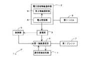
図5は第3の実施形態に係る無線通信装置1bの概略構成を示すブロック図である。図5の無線通信装置1bは、図1と共通する構成部分には同一の符号を付しており、以下では相違点を中心に説明する。 FIG. 5 is a block diagram illustrating a schematic configuration of a wireless communication device 1b according to the third embodiment. In the wireless communication device 1b of FIG. 5, the same reference numerals are given to the same components as those in FIG. 1, and the differences will be mainly described below.
図5の無線通信装置1bは、電力受信無線通信部2内の電力受信部8に第1コイル6が接続される点では図4と共通するが、第2無線通信部9に第2アンテナ10が接続される点で図4とは異なる。 5 is the same as FIG. 4 in that the
第2無線通信部9は、電力受信部8が第1コイル6による電磁誘導で受信した電力の一部を利用して、第2アンテナ10を介して不図示の電力送信装置にRF信号を送信するとともに、電力送信装置から送信されたRF信号を第2アンテナ10を介して受信する。 The second
このように、第3の実施形態の第2無線通信部9は、第1コイル6とは別個の第2アンテナ10を介して、電力送信装置と無線通信を行うため、電磁誘導が生じる距離よりも離れた距離に電力送信装置が存在する場合でも、蓄電部3に電力が蓄電されている限り、安定した無線通信を行うことができる。 As described above, since the second
(第4の実施形態)
第4の実施形態は、蓄電部3に蓄電された電力量が第1基準量を超えたことを電力送信装置と第1無線通信部4に通知するものである。(Fourth embodiment)
In the fourth embodiment, the power transmission device and the first
第4の実施形態に係る無線通信装置1の内部構成は、上述した図1、図4および図5のいずれでもよい。無線通信装置1内の制御部5は、蓄電部3に蓄電された電力量を継続してモニターし、電力量が第1基準量を超えると、第1トリガー信号を生成して、第2無線通信部9に供給する。第2無線通信部9は、第1トリガー信号を含むRF信号を不図示の電力送信装置と第1無線通信部4に送信する。このとき、第2無線通信部9は、図4の構成では第1コイル6を介して、図5の構成では第2アンテナ10を介して、上述した第1トリガー信号を含むRF信号を電力送信装置に送信する。 The internal configuration of the
この第1トリガー信号を受信した電力送信装置は、第1無線通信部4との無線通信が行える状態になったことを把握する。同様に、制御部5からの第1トリガー信号を受信した第1無線通信部4は、電力送信装置との無線通信を行うのに十分な電力が蓄電部3に蓄電されたことを把握する。そして、電力送信装置と第1無線通信部4は、お互いに無線通信を開始する。 The power transmission device that has received the first trigger signal recognizes that wireless communication with the first
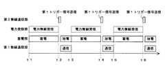
図6は第4の実施形態に係る無線通信装置1の動作タイミング図である。時刻t1で電力受信部8は電力送信装置からの電力の受信を開始して、受信した電力を蓄電部3に蓄電し始める。時刻t2になると、制御部5は、蓄電部3に蓄電された電力量が第1基準量を超えたことを検出して、第1トリガー信号を生成する。この第1トリガー信号は第2無線通信部9を介して電力送信装置に送信されるとともに、第1無線通信部4にも送信される。そして、第1無線通信部4は、電力送信装置との間で無線通信を開始する。 FIG. 6 is an operation timing chart of the
図7は図2よりも長い時間間隔での第4の実施形態に係る無線通信装置1の動作タイミング図である。図7に示すように、第1無線通信部4と電力送信装置は、第1トリガー信号を受信してから所定の期間だけ無線通信を行う。この所定の期間とは、蓄電部3に蓄電された電力量が第2基準量以下にならない期間である。これにより、第1無線通信部4と電力送信装置は、第1トリガー信号を受信した場合のみ、間歇的に無線通信を行うことになる。したがって、大容量のデータを送受する必要がある場合でも、間歇的に第1無線通信部4と電力送信装置で無線通信を行うことで、比較的短い時間で、大容量データの送受が可能となる。 FIG. 7 is an operation timing chart of the
ところで、第1トリガー信号だけだと、第1無線通信部4と電力送信装置は、蓄電部3に蓄電された電力量が第2基準量以下になったか否かを正しく判断できない。そこで、制御部5は、蓄電部3に蓄電された電力量が第2基準量以下になった場合に第2トリガー信号を生成して、この第2トリガー信号を第2無線通信部9を介して電力送信装置に送信するとともに、第1無線通信部4にも送信してもよい。 By the way, if it is only the 1st trigger signal, the 1st radio |
図8は第2トリガー信号を設けた場合の動作タイミング図である。図8に示すように、制御部5は、時刻t1で、蓄電部3に蓄電された電力量が第1基準量を超えたことを検知して第1トリガー信号を生成する。この第1トリガー信号を受信した第1無線通信部4と電力送信装置は無線通信を開始し、その後、時刻t2で、制御部5は、蓄電部3に蓄電された電力量が第2基準量以下になったことを検知して第2トリガー信号を生成する。この第2トリガー信号を受信した第1無線通信部4と電力送信装置は無線通信を停止する。 FIG. 8 is an operation timing chart when the second trigger signal is provided. As shown in FIG. 8, the
図9は図8よりも長い時間間隔での第4の実施形態に係る無線通信装置1の動作タイミング図である。図9に示すように、第1無線通信部4と電力送信装置は、第1トリガー信号を受信してから次に第2トリガー信号を受信するまでの間のみ、無線通信を行う。これにより、第1無線通信部4は、蓄電部3に蓄電された電力量が第1基準量を超えている場合のみ高速かつ高効率の無線通信を行うことになり、安定した高速通信を行うことができる。 FIG. 9 is an operation timing chart of the
このように、第4の実施形態では、蓄電部3に蓄電された電力量が第1基準量を超えた場合に第1トリガー信号を生成して、第1無線通信部4と電力送信装置に送信するようにしたため、第1無線通信部4と電力送信装置は、どのタイミングで無線通信を開始すればよいかを的確に把握でき、無駄な消費電力を費やさなくて済む。これに加えて、蓄電部3に蓄電された電力量が第2基準量以下になった場合に第2トリガー信号を生成して、第1無線通信部4と電力送信装置に送信するようにすれば、いったん開始した無線通信の停止時期を的確に把握でき、蓄電部3に蓄電された電力が低くなっても第1無線通信部4で無線通信を継続するおそれがなくなり、無線通信の安定度を向上できる。 As described above, in the fourth embodiment, when the amount of power stored in the
(第5の実施形態)
第5の実施形態は、第1無線通信部4が電力送信装置との間で無線通信を行うのに先立って行う接続処理に必要な情報を予め保持しておくものである。(Fifth embodiment)
In the fifth embodiment, information necessary for connection processing performed before the first
図10は第5の実施形態に係る無線通信装置1cの概略構成を示すブロック図である。図10の無線通信装置1cは、図1と共通する構成部分には同一の符号を付しており、以下では相違点を中心に説明する。 FIG. 10 is a block diagram showing a schematic configuration of a wireless communication apparatus 1c according to the fifth embodiment. In the wireless communication device 1c of FIG. 10, components that are the same as those in FIG. 1 are denoted by the same reference numerals, and the differences will be mainly described below.
図10の無線通信装置1cは、図1の構成に加えて、通信情報保持部11を備えている。通信情報保持部11は、第1無線通信部4を識別する情報と、第1無線通信部4の通信性能に関する情報と、第1無線通信部4の標準規格対応情報との少なくとも一つを保持する。 A wireless communication device 1c of FIG. 10 includes a communication information holding unit 11 in addition to the configuration of FIG. The communication information holding unit 11 holds at least one of information for identifying the first
通信情報保持部11に保持される情報は、第1無線通信部4が電力送信装置と無線通信を行うのに先立って行われる接続処理に必要な情報である。接続処理を行っている最中は、第1無線通信部4は電力送信装置との無線通信を行えないため、接続処理に要する時間が長いと、せっかく第1無線通信部4が高速かつ高効率の無線通信を行う能力を持っていたとしても、その能力を生かせなくなる。そこで、本実施形態では、接続処理に必要な情報を予め通信情報保持部11に保持しておくことで、接続処理に要する時間を短縮する。 The information held in the communication information holding unit 11 is information necessary for connection processing performed before the first
より具体的には、電力送信装置との高速通信を行うタイミングになると、第1無線通信部4は、通信情報保持部11から、電力送信装置との接続処理に必要な情報を読み出して、接続処理を行い、接続処理が完了すると、電力送信装置との高速通信を開始する。 More specifically, when it is time to perform high-speed communication with the power transmission device, the first
このように、第5の実施形態では、無線通信装置1c内に通信情報保持部11を設けて、第1無線通信部4と電力送信装置との接続処理に必要な情報の少なくとも一部を保持するため、第1無線通信部4と電力送信装置との接続処理に要する時間を短縮でき、無線通信を迅速に開始できるようになる。 As described above, in the fifth embodiment, the communication information holding unit 11 is provided in the wireless communication device 1c to hold at least a part of information necessary for the connection process between the first
(第6の実施形態)
上述した第1〜第5の実施形態では、無線通信装置1の内部構成について説明した。以下では、これらの無線通信装置1との間で電力の送受および無線通信を行う電力送信装置の構成について説明する。(Sixth embodiment)
In the first to fifth embodiments described above, the internal configuration of the
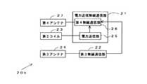
図11は電力送信装置20の概略構成を示すブロック図である。図11の電力送信装置20は、無線通信装置1に電力を送信するとともに無線通信装置1との無線通信を行う電力送信無線通信部21と、無線通信装置1との間で高速かつ高効率で無線通信を行う第3無線通信部22と、電力送信無線通信部21に接続される第2コイル23と、第3無線通信部22に接続される第3アンテナ24とを備えている。 FIG. 11 is a block diagram illustrating a schematic configuration of the
電力送信無線通信部21は、電力送信部25と第4無線通信部26を有する。電力送信部25は、第2コイル23にて電磁誘導により電力を送信する。 The power transmission
第3無線通信部22は、無線通信装置1内の第1無線通信部4との間で、高速かつ高効率の無線通信を行う。第4無線通信部26は、無線通信装置1内の第2無線通信部9との間で、低速かつ低効率の無線通信を行う。 The third
図12および図13は図11の電力送信装置20をより具体化したブロック図である。図12および図13では、図11と共通する構成部分には同一の符号を付しており、以下では相違点を中心に説明する。 FIGS. 12 and 13 are block diagrams illustrating the
図12の電力送信装置20aは、電力送信無線通信部21内の電力送信部25に第2コイル23が接続されている。電力送信部25は、第2コイル23の電磁誘導を利用して、RF信号を無線通信装置1に送信する。無線通信装置1内の電力受信部8は、電力送信部25が送信したRF信号から電力を取り出す。 In the
第4無線通信部26は、電力送信部25が送信するRF信号の振幅を変調した新たなRF信号を生成して、第2コイル23を介して電力受信部8に送信する。 The fourth
第3無線通信部22は、無線通信装置1内の第1無線通信部4との間で、高速かつ高効率の無線通信を行う。 The third
このように、図12の電力送信装置20a内の電力送信無線通信部21は、第2コイル23だけで、電力の送信と第4無線通信部26による無線通信を行うため、第4無線通信部26用のアンテナを別個に設けなくて済み、電力送信装置20の構成を簡略化でき、小型化が図れる。 As described above, the power transmission
ただし、第2コイル23による電磁誘導で無線通信を行うため、電力送信装置20aは、近接した距離に置かれた無線通信装置1との間で、NFCのような電磁誘導を利用した通信を行うことになる。 However, since wireless communication is performed by electromagnetic induction by the
一方、図13の電力送信装置20bは、第4無線通信部26用の第4アンテナ27を設ける点で図12と異なっている。第4無線通信部26は、第4アンテナ27を用いて、無線通信装置1内の第2無線通信部9と無線通信を行う。第4アンテナ27を用いる以上、第4無線通信部26は、NFCによる通信距離よりも遠くに位置する第2無線通信部9と無線通信を行うことができる。従って、図13の電力送信装置20bは、図12の電力送信装置20aよりも、第4無線通信部26の通信距離を広げることができ、使い勝手が向上する。 On the other hand, the
第4の実施形態で説明したように、無線通信装置1内の第2無線通信部9が第1トリガー信号を含むRF信号を送信する場合、図12および図13の第4無線通信部26は、この第1トリガー信号を受信することにより、無線通信装置1内の蓄電部3に蓄電されている電力量が第1基準量を超えたことを把握し、第3無線通信部22に無線通信を指示する。これを受けて、第3無線通信部22は、無線通信装置1内の第1無線通信部4と高速かつ高効率で無線通信を行う。 As described in the fourth embodiment, when the second
同様に、無線通信装置1内の第2無線通信部9が第2トリガー信号を含むRF信号を送信する場合、図12および図13の第4無線通信部26は、この第2トリガー信号を受信することにより、無線通信装置1内の蓄電部3に蓄電されている電力量が第2基準量以下になったことを把握し、第3無線通信部22に無線通信の停止を指示する。これを受けて、第3無線通信部22は、無線通信装置1内の第1無線通信部4との無線通信を停止する。 Similarly, when the second
このように、第6の実施形態では、第1乃至第5の実施形態に係る無線通信装置1の内部構成に合わせて、電力送信装置20内に電力送信無線通信部21と第3無線通信部22を設けるため、低速かつ低効率の無線通信は電力送信無線通信部21内の第4無線通信部26で連続的に行い、高速かつ高効率の無線通信は第3無線通信部22で間歇的に行うことができ、消費電力を抑制しつつ、簡易な構成で、低速かつ低効率の無線通信と高速かつ高効率の無線通信とを並行して行うことができる。 Thus, in the sixth embodiment, the power transmission
(その他の変形例)
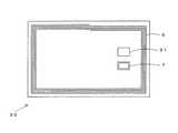
第1〜第5の実施形態における無線通信装置1は、ICカード等のカード形状であってもよい。図14は第1〜第6の実施形態における無線通信装置1を内蔵するICカード30の一例を示す図である。図14のICカード30は、第1〜第5の実施形態に係る無線通信装置1が内蔵されるICチップ31と、第1コイル6と、第1無線通信部4に接続された第1アンテナ7とを有する。無線通信装置1内の第2無線通信部9に、第1コイル6とは別個の第2アンテナ10(図5参照)が接続されている場合は、この第2アンテナ10もICカード30内に実装する必要があるが、図14では第2アンテナ10を省略している。また第1アンテナ7は、ICチップ31に内蔵されていてもよい。(Other variations)
The
なお、第1アンテナ7、第2アンテナ10および第1コイル6の形状は、無線通信帯域に応じて変化するため、図14に示したものに限定されない。また、1個のICチップ31ではなく、複数のICチップ31で無線通信装置1を構成してもよく、また、無線通信装置1を構成する一部部品は、ICチップ31ではなく、ディスクリート部品を実装してもよい。 In addition, since the shape of the
上述した各実施形態では、大容量データは第1無線通信部4を用いて間歇的に送信する例を説明したが、少量データで、かつ高速送信の必要がないデータについては、必ずしも第1無線通信部4で送信する必要はなく、第2無線通信部9で送信してもよい。すなわち、第1無線通信部4と第2無線通信部9のどちらを使用するかを、送信するデータごとに、任意に選択できるようにしてもよい。 In each of the above-described embodiments, an example in which large-capacity data is intermittently transmitted using the first
上述した各実施形態における蓄電部3は、電力を蓄電することができるものであれば、その形態は問わない。例えば、簡易にはキャパシタで構成してもよいし、出力電圧を制御できるようなレギュレータ機能を蓄電部3に持たせてもよい。また、蓄電部3に電力を蓄電するか、蓄電部3に蓄電された電力を放電するかを切り替えるスイッチを設けてもよい。さらに、蓄電部3に蓄電された電力は、無線通信装置1以外の周辺装置を駆動する目的に利用してもよい。例えば、蓄電部3に蓄電された電力を用いて、周辺装置内のメモリなどを駆動してもよい。 The
本発明の態様は、上述した個々の実施形態に限定されるものではなく、当業者が想到しうる種々の変形も含むものであり、本発明の効果も上述した内容に限定されない。すなわち、特許請求の範囲に規定された内容およびその均等物から導き出される本発明の概念的な思想と趣旨を逸脱しない範囲で種々の追加、変更および部分的削除が可能である。 The aspect of the present invention is not limited to the individual embodiments described above, and includes various modifications that can be conceived by those skilled in the art, and the effects of the present invention are not limited to the contents described above. That is, various additions, modifications, and partial deletions can be made without departing from the concept and spirit of the present invention derived from the contents defined in the claims and equivalents thereof.
1 無線通信装置、2 電力受信無線通信部、3 蓄電部、4 第1無線通信部、5 制御部、6 第1コイル、7 第1アンテナ、8 電力受信部、9 第2無線通信部、10 第2アンテナ、11 通信情報保持部、20 電力送信装置、21 電力送信無線通信部、22 第3無線通信部、24 第3アンテナ、25 電力送信部、26 第4無線通信部、27 第4アンテナ、30 ICカード DESCRIPTION OF
Claims (10)
Translated fromJapanese前記電力取得部で取得した電力の少なくとも一部を蓄電する蓄電部と、
前記蓄電部に蓄電された電力量が第1基準量を超えた場合に、前記蓄電部の電力を利用して、無線通信を行う第1無線通信部と、
前記電力取得部で取得した電力を利用して、前記第1無線通信部より低速で無線通信を行う第2無線通信部と、
前記蓄電部に蓄電された電力量が前記第1基準量を超えたことを示す第1トリガー信号を生成する制御部と、を備え、
前記第1無線通信部で無線通信する際の単位データ当たりの消費電力は、前記第2無線通信部で無線通信する際の単位データ当たりの消費電力よりも小さく、
前記第2無線通信部は、前記第1トリガー信号を含む第1RF信号を送信し、
前記第1無線通信部は、前記制御部から前記第1トリガー信号が供給されると、無線通信を開始する無線通信装置。A power acquisition unit for acquiring power by electromagnetic induction;
A power storage unit that stores at least part of the power acquired by the power acquisition unit;
A first wireless communication unit that performs wireless communication using the power of the power storage unit when the amount of power stored in the power storage unit exceeds a first reference amount;
A second wireless communication unit that performs wireless communication at a lower speed than the first wireless communication unit using the power acquired by the power acquisition unit;
A control unit that generates a first trigger signal indicating that the amount of power stored in the power storage unit exceeds the first reference amount ;
The power consumption per unit data when the wireless communication by the first radio communication unit israther smaller than the power consumption per unit data when the wireless communication with the second wireless communicationunit,
The second wireless communication unit transmits a first RF signal including the first trigger signal,
The first wireless communication unit is a wireless communication devicethat starts wireless communication when the first trigger signal is supplied from the control unit .
前記電力取得部で受信した電力の少なくとも一部を蓄電する蓄電部と、
前記蓄電部に蓄電された電力量が第1基準量を超えた場合に、前記蓄電部の電力を利用して、無線通信を行う第1無線通信部と、
前記電力取得部で受信した電力を利用して、前記第1無線通信部より低速で無線通信を行う第2無線通信部と、
前記蓄電部に蓄電された電力量が前記第1基準量を超えたことを示す第1トリガー信号を生成する制御部と、を備え、
前記第1無線通信部で無線通信する際の単位データ当たりの消費電力は、前記第2無線通信部で無線通信する際の単位データ当たりの消費電力よりも小さく、
前記第2無線通信部は、前記第1トリガー信号を含む第1RF信号を送信し、
前記第1無線通信部は、前記制御部から前記第1トリガー信号が供給されると、無線通信を開始する無線通信装置。A power acquisition unit for receiving power wirelessly;
A power storage unit that stores at least part of the power received by the power acquisition unit;
A first wireless communication unit that performs wireless communication using the power of the power storage unit when the amount of power stored in the power storage unit exceeds a first reference amount;
A second wireless communication unit that performs wireless communication at a lower speed than the first wireless communication unit using the power received by the power acquisition unit;
A control unit that generates a first trigger signal indicating that the amount of power stored in the power storage unit exceeds the first reference amount ;
The power consumption per unit data when the wireless communication by the first radio communication unit israther smaller than the power consumption per unit data when the wireless communication with the second wireless communicationunit,
The second wireless communication unit transmits a first RF signal including the first trigger signal,
The first wireless communication unit is a wireless communication devicethat starts wireless communication when the first trigger signal is supplied from the control unit .
前記第2無線通信部は、前記第2RF信号により得られる電力の少なくとも一部を利用して、前記第1RF信号に変調を施した電力変調信号を生成し、前記第1コイルから送信するとともに、前記第2RF信号を前記第1コイルを介して受信し、
前記蓄電部は、前記第2RF信号により得られる電力の少なくとも一部を蓄電する請求項1または2に記載の無線通信装置。A first coil connected to the power acquisition unit and capable of receiving asecond RF signal by electromagnetic induction;
The second wireless communication unit generates a power modulation signal obtained by modulatingthe first RF signal using at least a part of power obtained fromthe second RF signal, and transmits the power modulation signal from the first coil. And receivingthe second RF signal through the first coil,
The wireless communication device according to claim 1, whereinthe power storage unit stores at least a part of electric power obtained bythe second RF signal.
前記電力取得部に接続され、前記第3RF信号を電磁誘導により受信可能な第1コイルと、
前記第2無線通信部に接続され、前記第3RF信号を受信するとともに、前記第4RF信号を送信する第2アンテナと、を備える請求項1乃至3のいずれかに記載の無線通信装置。A first antenna connected to the first wireless communication unit for receiving athird RF signal and transmitting afourth RF signal;
A first coil connected to the power acquisition unit and capable of receivingthe third RF signal by electromagnetic induction;
4. The wireless communication device according to claim 1, further comprising: a second antenna that is connected to the second wireless communication unit, receivesthe third RF signal, and transmitsthe fourth RF signal. 5.
前記第2無線通信部は、前記制御部が生成した前記第2トリガー信号を含む前記第1RF信号を送信し、
前記第1無線通信部は、前記制御部から前記第2トリガー信号が供給されると、無線通信を停止する請求項1乃至4のいずれかに記載の無線通信装置。The control unit generates a second trigger signal when the amount of power stored in the power storage unit falls below a second reference amount,
The second wireless communication unit transmitsthe first RF signal including the second trigger signal generated by the control unit,
The first radio communication unit, when the second trigger signal is supplied from the control unit, the radio communication apparatus according toany one of claims1 to 4 to stop the wireless communication.
前記第1無線通信部は、前記通信情報保持部に保持された情報を参照して接続処理を行う請求項1乃至5のいずれかに記載の無線通信装置。A communication information holding unit that holds at least one of information for identifying the first wireless communication unit, information on communication performance of the first wireless communication unit, and standard-compliant information of the first wireless communication unit; ,
The first radio communication unit, a wireless communication apparatus according to any one of claims 1 to5 perform connection processing with reference to the information held in the communication information storage unit.
前記第1無線通信部との間で無線通信を行う第3無線通信部と、
前記第3無線通信部よりも低速に前記第2無線通信部と無線通信を行って、前記第1トリガー信号を受信する第4無線通信部と、を有し、
前記第3無線通信部で無線通信する際の単位データ当たりの消費電力は、前記第4無線通信で無線通信する際の単位データ当たりの消費電力よりも小さい無線通信装置。A power transmission unit that transmits power to the power acquisition unit in the wireless communication device according to claim4 or5 ,
A third wireless communication unit that performs wireless communication with the first wireless communication unit;
A fourth wireless communication unit that performs wireless communication with the second wireless communication unit at a lower speed than the third wireless communication unit and receives the first trigger signal;
A wireless communication apparatus, wherein power consumption per unit data when performing wireless communication with the third wireless communication unit is smaller than power consumption per unit data when performing wireless communication with the fourth wireless communication.
前記第4無線通信部は、前記第2コイルを介して前記第2無線通信部と無線通信を行う請求項7に記載の無線通信装置。A second coil connected to the power transmitter and capable of transmitting power by electromagnetic induction;
The wireless communication device according to claim7 , wherein the fourth wireless communication unit performs wireless communication with the second wireless communication unit via the second coil.
前記電力送信部に接続され、電磁誘導による電力伝送が可能な第2コイルと、
前記第4無線通信部に接続され、前記第2無線通信部から送信された第7RF信号を受信するとともに、前記第2無線通信部に第8RF信号を送信する第4アンテナと、を備える請求項7または8に記載の無線通信装置。A third antenna connected to the third wireless communication unit and receiving afifth RF signal transmitted from the power transmission unit and transmitting asixth RF signal tothe power transmission unit;
A second coil connected to the power transmitter and capable of transmitting power by electromagnetic induction;
A fourth antenna connected to the fourth wireless communication unit and receiving aseventh RF signal transmitted from the second wireless communication unit and transmitting aneighth RF signal to the second wireless communication unit; The wireless communication apparatus according to claim7 or8 .
前記電力取得部に接続される第1コイルと、
前記第1無線通信部に接続される第1アンテナと、
を備えたICカード装置。An IC chip comprising a wireless communication device according to claim 1 or 2;
A first coil connected to the power acquisition unit;
A first antenna connected to the first wireless communication unit;
IC card device comprising:
Priority Applications (4)
| Application Number | Priority Date | Filing Date | Title |
|---|---|---|---|
| JP2011259464AJP5843583B2 (en) | 2011-11-28 | 2011-11-28 | Wireless communication device, power transmission device, and IC card device |
| US13/608,906US8989659B2 (en) | 2011-11-28 | 2012-09-10 | Wireless communication device, power transmitter, and IC card device |
| EP12184189.4AEP2597781A2 (en) | 2011-11-28 | 2012-09-13 | Wireless communication device, power transmitter, and ic card device |
| CN2012103883549ACN103138783A (en) | 2011-11-28 | 2012-10-12 | Wireless communication device, power transmitter, and IC card device |
Applications Claiming Priority (1)
| Application Number | Priority Date | Filing Date | Title |
|---|---|---|---|
| JP2011259464AJP5843583B2 (en) | 2011-11-28 | 2011-11-28 | Wireless communication device, power transmission device, and IC card device |
Publications (2)
| Publication Number | Publication Date |
|---|---|
| JP2013115577A JP2013115577A (en) | 2013-06-10 |
| JP5843583B2true JP5843583B2 (en) | 2016-01-13 |
Family
ID=46980755
Family Applications (1)
| Application Number | Title | Priority Date | Filing Date |
|---|---|---|---|
| JP2011259464AExpired - Fee RelatedJP5843583B2 (en) | 2011-11-28 | 2011-11-28 | Wireless communication device, power transmission device, and IC card device |
Country Status (4)
| Country | Link |
|---|---|
| US (1) | US8989659B2 (en) |
| EP (1) | EP2597781A2 (en) |
| JP (1) | JP5843583B2 (en) |
| CN (1) | CN103138783A (en) |
Families Citing this family (10)
| Publication number | Priority date | Publication date | Assignee | Title |
|---|---|---|---|---|
| JP4894826B2 (en)* | 2008-07-14 | 2012-03-14 | ソニー株式会社 | COMMUNICATION DEVICE, COMMUNICATION SYSTEM, NOTIFICATION METHOD, AND PROGRAM |
| JP5603647B2 (en)* | 2009-05-13 | 2014-10-08 | キヤノン株式会社 | Power feeding device, power feeding device control method, and power feeding communication system |
| US20120203620A1 (en) | 2010-11-08 | 2012-08-09 | Douglas Howard Dobyns | Techniques For Wireless Communication Of Proximity Based Marketing |
| US8929809B2 (en) | 2011-03-22 | 2015-01-06 | Radeum, Inc. | Techniques for wireless communication of proximity based content |
| US8880100B2 (en) | 2011-03-23 | 2014-11-04 | Radium, Inc. | Proximity based social networking |
| US20140191712A1 (en)* | 2013-01-10 | 2014-07-10 | Adam D. Rea | Power delivery including out-of-band communication |
| JP6130711B2 (en)* | 2013-04-17 | 2017-05-17 | キヤノン株式会社 | Communication device, control method, and program |
| US9780837B2 (en) | 2014-08-29 | 2017-10-03 | Freelinc Technologies | Spatially enabled secure communications |
| US10164685B2 (en) | 2014-12-31 | 2018-12-25 | Freelinc Technologies Inc. | Spatially aware wireless network |
| US10122182B2 (en)* | 2015-02-27 | 2018-11-06 | Qualcomm Incorporated | Multi-turn coil on metal backplate |
Family Cites Families (11)
| Publication number | Priority date | Publication date | Assignee | Title |
|---|---|---|---|---|
| JPH08265211A (en)* | 1995-03-22 | 1996-10-11 | Sony Corp | Integrated circuit and transmitter-receiver |
| JP4462614B2 (en)* | 2004-07-05 | 2010-05-12 | ソニー・エリクソン・モバイルコミュニケーションズ株式会社 | Short-range wireless communication system, portable terminal device, and wireless communication device |
| KR100657381B1 (en) | 2004-10-21 | 2006-12-14 | 주식회사 서비전자 | Battery modem using wireless short range communication technology |
| JP2006279577A (en)* | 2005-03-29 | 2006-10-12 | Fujitsu Ltd | Dual mode communication method and dual mode communication terminal |
| JP4506856B2 (en) | 2008-03-10 | 2010-07-21 | ソニー株式会社 | Communication apparatus and communication method |
| JP5159396B2 (en) | 2008-04-03 | 2013-03-06 | キヤノン株式会社 | Communication device, control method thereof, and program |
| JP4645698B2 (en)* | 2008-08-19 | 2011-03-09 | ソニー株式会社 | Wireless communication device and power receiving device |
| US8126433B2 (en)* | 2008-09-15 | 2012-02-28 | Sony Ericsson Mobile Communications Ab | Electronic devices and methods that communicate via transferjet and NFC transmitter and receiver pairing |
| JP2010108134A (en)* | 2008-10-29 | 2010-05-13 | Sony Corp | Reader/writer, information processor, communication method, program, and communication system |
| JP5310077B2 (en) | 2009-02-23 | 2013-10-09 | ソニー株式会社 | Wireless communication apparatus, wireless communication method and program |
| JP2010200168A (en)* | 2009-02-26 | 2010-09-09 | Toshiba Corp | Electronic apparatus, expansion apparatus and electronic apparatus system |
- 2011
- 2011-11-28JPJP2011259464Apatent/JP5843583B2/ennot_activeExpired - Fee Related
- 2012
- 2012-09-10USUS13/608,906patent/US8989659B2/ennot_activeExpired - Fee Related
- 2012-09-13EPEP12184189.4Apatent/EP2597781A2/ennot_activeWithdrawn
- 2012-10-12CNCN2012103883549Apatent/CN103138783A/enactivePending
Also Published As
| Publication number | Publication date |
|---|---|
| JP2013115577A (en) | 2013-06-10 |
| EP2597781A2 (en) | 2013-05-29 |
| CN103138783A (en) | 2013-06-05 |
| US20130137369A1 (en) | 2013-05-30 |
| US8989659B2 (en) | 2015-03-24 |
Similar Documents
| Publication | Publication Date | Title |
|---|---|---|
| JP5843583B2 (en) | Wireless communication device, power transmission device, and IC card device | |
| JP6702688B2 (en) | Wireless power transmission system and power receiving device | |
| US9601930B2 (en) | Power transmitting device having device discovery and power transfer capabilities | |
| EP2713472B1 (en) | Power receiving device having device detection and power transfer capabilities | |
| KR101752378B1 (en) | Wireless device detection and communication apparatus and system | |
| US9185662B2 (en) | Coordinated wireless communication and power delivery | |
| US20060145660A1 (en) | Method and apparatus for near field communications | |
| US20140347007A1 (en) | Wireless Power Transfer (WPT) for a Mobile Communication Device | |
| US20080211455A1 (en) | Rechargeable Power Supply, Battery Device, Contactless Charger System And Method For Charging Rechargeable Battery Cell | |
| EP3588792A1 (en) | Reducing power consumption for connection establishment in near field communication systems | |
| KR20120135885A (en) | Wireless power transmitting/receiving system comprising transmitter and receiver, two-way communication method between the transmitter and the receiver, and the apparatuses | |
| KR20110103297A (en) | Wireless power charging method and device | |
| EP1895450A3 (en) | Semiconductor device and power receiving device | |
| KR20140135794A (en) | Coexistence between nfc and wct | |
| JP2014533172A5 (en) | ||
| CN106981900A (en) | Wireless charging method and device | |
| US11405074B2 (en) | NFC interface with energy management function | |
| JP2014138547A (en) | Power supply device and control method of the same, power supply system, program, and storage medium | |
| CN109698713B (en) | NFC interface with energy management function | |
| CN104679142A (en) | Docking station for intelligent electronic equipment | |
| US20130137370A1 (en) | Modified connection establishment for reducing power consumption in near field communication systems | |
| CN104124996B (en) | Realize the method and system of radio energy transmission system wireless communication | |
| CN103187993B (en) | A kind of communication means and terminal | |
| KR20190112979A (en) | Method and apparatus for bi-directional communication in wireless power receiver | |
| US9949108B2 (en) | Method for detecting an adjacent active near-field communication device |
Legal Events
| Date | Code | Title | Description |
|---|---|---|---|
| A621 | Written request for application examination | Free format text:JAPANESE INTERMEDIATE CODE: A621 Effective date:20140131 | |
| A977 | Report on retrieval | Free format text:JAPANESE INTERMEDIATE CODE: A971007 Effective date:20141224 | |
| A131 | Notification of reasons for refusal | Free format text:JAPANESE INTERMEDIATE CODE: A131 Effective date:20150106 | |
| A521 | Request for written amendment filed | Free format text:JAPANESE INTERMEDIATE CODE: A523 Effective date:20150309 | |
| A02 | Decision of refusal | Free format text:JAPANESE INTERMEDIATE CODE: A02 Effective date:20150619 | |
| A521 | Request for written amendment filed | Free format text:JAPANESE INTERMEDIATE CODE: A523 Effective date:20150924 | |
| A911 | Transfer to examiner for re-examination before appeal (zenchi) | Free format text:JAPANESE INTERMEDIATE CODE: A911 Effective date:20151002 | |
| TRDD | Decision of grant or rejection written | ||
| A01 | Written decision to grant a patent or to grant a registration (utility model) | Free format text:JAPANESE INTERMEDIATE CODE: A01 Effective date:20151020 | |
| A61 | First payment of annual fees (during grant procedure) | Free format text:JAPANESE INTERMEDIATE CODE: A61 Effective date:20151117 | |
| LAPS | Cancellation because of no payment of annual fees |