JP5843547B2 - Method of manufacturing friction stir welding material - Google Patents
Method of manufacturing friction stir welding materialDownload PDFInfo
- Publication number
- JP5843547B2 JP5843547B2JP2011212241AJP2011212241AJP5843547B2JP 5843547 B2JP5843547 B2JP 5843547B2JP 2011212241 AJP2011212241 AJP 2011212241AJP 2011212241 AJP2011212241 AJP 2011212241AJP 5843547 B2JP5843547 B2JP 5843547B2
- Authority
- JP
- Japan
- Prior art keywords
- pin
- joining
- friction stir
- stir welding
- tool
- Prior art date
- Legal status (The legal status is an assumption and is not a legal conclusion. Google has not performed a legal analysis and makes no representation as to the accuracy of the status listed.)
- Active
Links
Images


Classifications
- B—PERFORMING OPERATIONS; TRANSPORTING
- B23—MACHINE TOOLS; METAL-WORKING NOT OTHERWISE PROVIDED FOR
- B23K—SOLDERING OR UNSOLDERING; WELDING; CLADDING OR PLATING BY SOLDERING OR WELDING; CUTTING BY APPLYING HEAT LOCALLY, e.g. FLAME CUTTING; WORKING BY LASER BEAM
- B23K20/00—Non-electric welding by applying impact or other pressure, with or without the application of heat, e.g. cladding or plating
- B23K20/12—Non-electric welding by applying impact or other pressure, with or without the application of heat, e.g. cladding or plating the heat being generated by friction; Friction welding
- B23K20/122—Non-electric welding by applying impact or other pressure, with or without the application of heat, e.g. cladding or plating the heat being generated by friction; Friction welding using a non-consumable tool, e.g. friction stir welding
- B23K20/1265—Non-butt welded joints, e.g. overlap-joints, T-joints or spot welds
- B—PERFORMING OPERATIONS; TRANSPORTING
- B23—MACHINE TOOLS; METAL-WORKING NOT OTHERWISE PROVIDED FOR
- B23K—SOLDERING OR UNSOLDERING; WELDING; CLADDING OR PLATING BY SOLDERING OR WELDING; CUTTING BY APPLYING HEAT LOCALLY, e.g. FLAME CUTTING; WORKING BY LASER BEAM
- B23K20/00—Non-electric welding by applying impact or other pressure, with or without the application of heat, e.g. cladding or plating
- B23K20/12—Non-electric welding by applying impact or other pressure, with or without the application of heat, e.g. cladding or plating the heat being generated by friction; Friction welding
- B23K20/122—Non-electric welding by applying impact or other pressure, with or without the application of heat, e.g. cladding or plating the heat being generated by friction; Friction welding using a non-consumable tool, e.g. friction stir welding
- B23K20/1225—Particular aspects of welding with a non-consumable tool
- B—PERFORMING OPERATIONS; TRANSPORTING
- B23—MACHINE TOOLS; METAL-WORKING NOT OTHERWISE PROVIDED FOR
- B23K—SOLDERING OR UNSOLDERING; WELDING; CLADDING OR PLATING BY SOLDERING OR WELDING; CUTTING BY APPLYING HEAT LOCALLY, e.g. FLAME CUTTING; WORKING BY LASER BEAM
- B23K2101/00—Articles made by soldering, welding or cutting
- B23K2101/18—Sheet panels
- B—PERFORMING OPERATIONS; TRANSPORTING
- B23—MACHINE TOOLS; METAL-WORKING NOT OTHERWISE PROVIDED FOR
- B23K—SOLDERING OR UNSOLDERING; WELDING; CLADDING OR PLATING BY SOLDERING OR WELDING; CUTTING BY APPLYING HEAT LOCALLY, e.g. FLAME CUTTING; WORKING BY LASER BEAM
- B23K2103/00—Materials to be soldered, welded or cut
- B23K2103/18—Dissimilar materials
- B23K2103/20—Ferrous alloys and aluminium or alloys thereof
- Y—GENERAL TAGGING OF NEW TECHNOLOGICAL DEVELOPMENTS; GENERAL TAGGING OF CROSS-SECTIONAL TECHNOLOGIES SPANNING OVER SEVERAL SECTIONS OF THE IPC; TECHNICAL SUBJECTS COVERED BY FORMER USPC CROSS-REFERENCE ART COLLECTIONS [XRACs] AND DIGESTS
- Y10—TECHNICAL SUBJECTS COVERED BY FORMER USPC
- Y10T—TECHNICAL SUBJECTS COVERED BY FORMER US CLASSIFICATION
- Y10T428/00—Stock material or miscellaneous articles
- Y10T428/24—Structurally defined web or sheet [e.g., overall dimension, etc.]
- Y10T428/24479—Structurally defined web or sheet [e.g., overall dimension, etc.] including variation in thickness
- Y10T428/24612—Composite web or sheet
Landscapes
- Engineering & Computer Science (AREA)
- Mechanical Engineering (AREA)
- Pressure Welding/Diffusion-Bonding (AREA)
Description
Translated fromJapanese本発明は、第1部材に、この第1部材とは材質が異なる第2部材を重ねた形態で、第1部材に第2部材を摩擦撹拌接合法で接合してなる摩擦撹拌接合材の製造方法に関する。The present invention provides a friction stir welding materialproduced by joining a second member to a first member by a friction stir welding method in a form in which a second member made of a material different from that of the first member is stacked on the first member. It relatesto a method.
鋼板とアルミニウム板とを接合する技術の一つとして摩擦撹拌接合法が知られている(例えば、特許文献1(図2)参照。)。 A friction stir welding method is known as one technique for joining a steel plate and an aluminum plate (see, for example, Patent Document 1 (FIG. 2)).
特許文献1を次図に基づいて説明する。
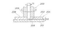
図15は従来の技術の基本原理を説明する図であり、摩擦撹拌接合法では、第1部材201に、この第1部材201とは材質が異なる第2部材202を重ね、この第2部材202に矢印(1)のように回転する接合ツール203のピン204を挿入する。このピン204の先端を第1部材201の第2部材側面から高さh3の位置に配置した状態で、接合ツール203を相対的に移動させる。
FIG. 15 is a diagram for explaining the basic principle of the conventional technique. In the friction stir welding method, a
回転中のピン204と第2部材202の間に摩擦熱が生じ、この摩擦熱で第2部材202が軟化する。軟化物は固化すると、接合部208となり、第1部材201に第2部材202を接合する役割を果たす。結果、第1部材201に第2部材202が接合されて摩擦撹拌接合材205が得られる。
ところで、設計指示や施工指示等により、接合部208の長さが第2部材202の長さ未満であることがある。この場合の断面図を次に説明する。Friction heat is generated between the rotating
By the way, the length of the
図16は従来の摩擦撹拌接合材の断面図であり、第2部材202に、接合ツール203のピン204の抜き跡に相当する穴206が形成され、第1部材201の第2部材側面207が外方に露出する。第1部材201が低電位の金属であり、第2部材202が高電位の金属であって、第2部材202の穴206及び第1部材201の第2部材側面207に水が浸入すると、第2部材202から水を介して第1部材201へ電流が流れる。この電流により、第2部材側面207が腐食する。 FIG. 16 is a cross-sectional view of a conventional friction stir welding material. A
対策として、第2部材202の穴206を栓部材で塞ぐことが挙げられるが、穴206に栓部材を取付ける工数が増加する。
もう一つの対策として、穴206を軟化した第2部材202(軟化物)で埋めることが挙げられる。穴206を軟化物で埋めるために、図15において、軟化物からピン204を引抜き、白抜き矢印のように回転するツール本体209を軟化物に向けて押出す。このツール本体209の押出しにより、ツール本体209で軟化物が押圧される。押圧された軟化物が穴に流れ込むと、穴が軟化物で埋められる。しかし、上記穴埋め作業は、ピン204を引抜いた後に実施される別作業であるから、工数の増加に繋がる。As a countermeasure, the
Another countermeasure is to fill the
そこで、より少ない工数で、腐食の発生を防止することができる摩擦撹拌接合材の製造方法が求められる。Therefore, amethod formanufacturing a friction stir welding material that can prevent the occurrence of corrosion with fewer man-hours is required.
本発明は、より少ない工数で、腐食の発生を防止することができる摩擦撹拌接合材を提供することを課題とする。 An object of the present invention is to provide a friction stir welding material that can prevent the occurrence of corrosion with fewer man-hours.
請求項1に係る発明は、第1部材に、この第1部材とは材質が異なる第2部材を重ね、この第2部材に摩擦撹拌接合法の接合ツールのピンを挿入し、前記第2部材の一端から接合を始め、他端に到達する前の接合終端部で前記ピンを抜くことにより、前記第1部材に前記第2部材を接合してなる摩擦撹拌接合材であって、前記第2部材のうち接合終端部には、一般接合面よりも前記接合ツール側へ突出する凸部が一体的に設けられ、前記凸部は、前記ピンの長さより高く形成されている摩擦撹拌接合材の製造方法を特徴とする。According to the first aspect of the present invention, a second member made of a material different from that of the first member is stacked on the first member, and a pin of a welding tool of a friction stir welding method is inserted into the second member. The friction stir welding material is formed by joining the second member to the first member by pulling out the pin at the joining terminal portion before starting the joining and reaching the other end. Of the members, the joint terminal portion is integrally provided with a convex portion that protrudes toward the joining tool from the general joint surface, and the convex portion is formed of a friction stir welding material formed higher than the length of the pin. Features amanufacturing method .
請求項2に係る発明は、第1部材に、この第1部材とは材質が異なる第2部材を重ね、この第2部材に摩擦撹拌接合法の接合ツールのピンを挿入し、前記ピンは前記第1部材の表面に当接しながら回転しており、前記第2部材の一端から接合を始め、他端に到達する前の接合終端部で前記ピンを抜くことにより、前記第1部材に前記第2部材を接合してなる摩擦撹拌接合材であって、前記第1部材の接合終端部には、前記第2部材側に開口する凹部が一体に設けられ、前記凹部には前記第2部材の一部が流入し、前記第2部材には前記凹部側に突出する凸部が形成され、前記接合端部において、前記ピンが前記第2部材に当接することなく引き抜かれている摩擦撹拌接合材の製造方法ことを特徴とする。According to a second aspect of the present invention, a second member made of a material different from that of the first member is stacked on the first member, and a pin of a friction stir welding method welding tool is inserted into the second member. Rotating while abutting against the surface of the first member, starting the joining from one end of the second member, and pulling out the pin at the joining terminal portion before reaching the other end, A friction stir welding material formed by joining two members, wherein a joint opening end portion of the first member is integrally provided with a concave portion that opens to the second member side, and the concave portion of the second member is provided in the concave portion. Friction stir welding material in which a part flows in, and the second member is formed with a convex portion protruding toward the concave portion, and the pin is pulled out without contacting the second member at the joint end portionThe manufacturing method of the above.
請求項1に係る発明では、第2部材に、接合ツール側へ突出する凸部が一体的に設けられ、この凸部は接合ツールのピンの長さより高く形成されている。また、凸部に接合終端部が設けられ、この接合終端部で、第2部材の他端に到達する前のピンが抜かれる。接合終了時にピンを接合終端部で抜き、接合終端部が固化すると、第2部材に、ピンの体積分に相当するピン跡凹みが形成される。このピン跡凹みの深さは、凸部の高さよりも小さいので、第2部材に、凸部の高さからピン跡凹みの深さを引いた分の肉厚が残る。第2部材に肉厚を残す作業は、接合終了時にピンを接合終端部から抜くだけであり、別途作業を要しないため、作業工数の低減に繋がる。 In the invention which concerns on
加えて、上記肉厚により、第1部材の第2部材側面が外部に露出することがなく、第1部材と第2部材が湿潤雰囲気に置かれ、第1部材が低電位の金属、第2部材が高電位の金属であっても、第1部材に腐食が発生することを防止できる。したがって、より少ない工数で、腐食の発生を防止することができる摩擦撹拌接合材を提供できる。 In addition, due to the above thickness, the second member side surface of the first member is not exposed to the outside, the first member and the second member are placed in a humid atmosphere, the first member is a low potential metal, the second Even if the member is a high-potential metal, corrosion of the first member can be prevented. Therefore, it is possible to provide a friction stir welding material that can prevent the occurrence of corrosion with fewer man-hours.
請求項2に係る発明では、第1部材に、第2部材側に開口する凹部が一体的に設けられている。この凹部に対応する第2部材の対応部位に、接合終端部が設けられている。接合ツールのピンが接合終了時に接合終端部に到達すると、接合終端部の周辺材料は、ピンと接合終端部の間に生じる摩擦熱で軟化する。軟化した接合終端部の周辺材料が回転しているピンに撹拌され、凹部に流入することで、接合終端部の周辺材料は凹部に充填される。充填後、固化した接合終端部の周辺材料は、凹部に接合され且つ嵌っている突起部であり、接合終端部の周辺材料が凹部に嵌合することになる。したがって、第1部材に第2部材が接合されることに加えて、接合終端部の周辺材料が凹部に嵌合することで、第1部材に対する第2部材の接合をより強化することができる。 In the invention which concerns on
本発明の実施の形態を添付図に基づいて以下に説明する。 Embodiments of the present invention will be described below with reference to the accompanying drawings.
本発明の実施例を図面に基づいて説明する。
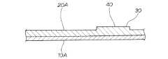
図1に示されるように、下側に配置されている第1部材10Aに、第2部材20Aを矢印(2)のように重ねて、第1部材10Aに対して第2部材20Aを位置決めする。第2部材20Aは、第1部材10Aとは材質が異なる部材である。次に第1部材10A及び第2部材20Aの断面構造を図2で説明する。Embodiments of the present invention will be described with reference to the drawings.
As shown in FIG. 1, the
図2に示されるように、第2部材20Aに、接合ツール(後述)側へ突出する円柱状の第2凸部30が一体的に設けられている。この第2凸部30は接合ツールのピン(後述)の長さ(後述)より高く形成されている。 As shown in FIG. 2, a cylindrical second
加えて、第2凸部30に接合終端部40(詳細後述)が設けられている。この接合終端部40は、第2部材20Aの一端(図1、符号21)から接合を始め、他端(図1、符号22)に到達する前にピンを抜くために用いる部位である。 In addition, a junction termination portion 40 (detailed later) is provided on the second
以上に述べた第1部材10A及び第2部材20Aに施す摩擦撹拌接合法を次に述べる。
図3において、(a)に示されるように、矢印(3)のように回転している接合ツール50のピン51が第2部材20Aに挿入されている。回転中のピン51が、第2部材20Aに接触するので、摩擦熱が生じる。この摩擦熱で、ピン51周辺の第2部材20Aが軟化する。接合ツール50を矢印(4)のように相対的に移動させる。Next, the friction stir welding method applied to the
In FIG. 3, as shown in (a), the
(b)に示されるように、接合ツール50を矢印(5)のようにさらに相対的に移動させる。
(c)に示されるように、接合ツール50が接合終端部40に移動し、この接合終端部40で矢印(6)のようにピン51を抜く。As shown in (b), the joining
As shown in (c), the joining
(d)に示されるように、軟化した第2部材20Aが固化すると、第2部材20Aに、ピン51の体積分に相当するピン跡凹み61が形成される。また、第1部材10Aに第2部材20Aが接合されて摩擦撹拌接合材70Aが得られる。81は接合部である。 As shown in (d), when the softened
(c)において、第2部材20Aに、接合ツール50側へ突出する第2凸部30が一体的に設けられ、この第2凸部30の高さH1は接合ツール50のピン51の長さh1より高い。また、第2凸部30に接合終端部40が設けられ、この接合終端部40で、第2部材20Aの他端(図1、符号22)に到達する前のピン51が抜かれる。接合終了時にピン51を接合終端部40で抜き、接合終端部40が固化すると、(d)に示されるように、第2部材20Aに、ピン51の体積分に相当するピン跡凹み61が形成される。このピン跡凹み61の深さh2は、第2凸部30の高さH1よりも小さいので、第2部材20Aに、第2凸部30の高さH1からピン跡凹み61の深さh2を引いた分の肉厚t1が残る。第2部材20Aに肉厚t1を残す作業は、接合終了時にピン51を接合終端部40から抜くだけであり、別途作業を要しないため、作業工数の低減に繋がる。 In (c), the 2nd
加えて、上記肉厚t1により、第1部材10Aの第2部材側面82が外部に露出することがなく、第1部材10Aと第2部材20Aが湿潤雰囲気に置かれ、第1部材10Aが低電位の金属、第2部材20Aが高電位の金属であっても、第1部材10Aに腐食が発生することを防止できる。したがって、より少ない工数で、腐食の発生を防止することができる摩擦撹拌接合材70Aを提供できる。 In addition, due to the thickness t1, the second
これまでの説明では、第2部材20Aに第2凸部30を設けることで、接合終端部40を確保した。第2部材に接合終端部を確保する手段は、他にも考えられる。そこで、第2部材に接合終端部を確保することができる他の例を次に説明する。 In the description so far, the joining
図4において、図1と共通の構造は符号を流用して詳細な説明を省略する。主たる変更点は、第1部材に穴部を設け、第2部材に第1部材側に突出する凸部を設けたことである。
下側に配置されている第1部材10Bに、第2部材20Bを矢印(7)のように重ねる。同時に、第1部材10Bに設けた円状の第1穴部90(詳細後述)に、第2部材20Bに設けた円柱状の第2凸部100(詳細後述)を矢印(8)のように挿入する。これで第1部材10Bに対して第2部材20Bが位置決めされる。In FIG. 4, the same structure as that in FIG. The main change is that the first member is provided with a hole, and the second member is provided with a convex portion protruding toward the first member.
The
なお、第2部材20Bは、第1部材10Bとは材質が異なる部材である。次に第1部材10B及び第2部材20Bの断面構造を図5で説明する。 The
図5に示されるように、第2部材20Bに、第1部材10B側へ突出する第2凸部100が一体的に設けられている。加えて、第2凸部100に対応する第2部材20Bのツール側面に、接合終端部110が設けられている。 As shown in FIG. 5, the
一方、第1部材10Bに、第2凸部100の外径D1よりも大径の内径D2を有する第1穴部90が設けられている。 On the other hand, the
以上に述べた第1部材10B及び第2部材20Bに施す摩擦撹拌接合法を次に述べる。
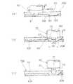
図6において、(a)に示されるように、矢印(9)のように回転している接合ツール50のピン51が第2部材20Bに挿入されている。回転中のピン51は、第2部材20Bに接触するので、摩擦熱が生じる。この摩擦熱で、ピン51周辺の第2部材20Bが軟化する。接合ツール50を矢印(10)のように相対的に移動させる。Next, the friction stir welding method applied to the
In FIG. 6, as shown in (a), the
(b)に示されるように、接合ツール50が接合終端部110に移動し、ピン51で撹拌された第2部材20Bの第2凸部100が第1穴部90を埋めている。次に接合終端部110で矢印(11)のようにピン51を抜く。 As shown in (b), the joining
(c)に示されるように、軟化した第2部材20Bが固化すると、第2部材20Bに、ピン51の体積分に相当するピン跡凹み111が形成される。また、第1部材10Bに第2部材20Bが接合されて摩擦撹拌接合材70Bが得られる。112は接合部である。
第2部材20Bのツール側面113は、接合後にピン跡凹み111を有すると共に略平面に形成される。ツール側面113にピン跡凹み111が設けられていても、ピン跡凹み111の周囲は略平面であるから、ツール側面113に別途部材を取付けることが可能となる。As shown in (c), when the softened
The
(b)において、ピン51の外径をd1、第1穴部90の内径をD2とすると、D2>d1である。好ましくは、D2=1.6d1である。D2<1.6d1のとき、第1穴部90に対する第2部材20Bの充填が過剰となる。D2>1.6d1のとき、第1穴部90に対する第2部材20Bの充填が不足する。なお、上記第1穴部90の内径D2とピン51の外径d1の寸法比は、本実施例における一例であり、第1穴部の内径や深さ、ピンの外径や長さ等は、第2部材の充填が十分になるように適宜調整できる。 In (b), if the outer diameter of the
上記第1部材10Bでは、第1穴部90を備えるようにした。この第1穴部90に第2部材20Bの第2凸部100が充填されると、第2凸部100は外側から見えることになる。ところで、第1穴部に充填された第2凸部は、外側から見えない方が外観性が向上する。そこで、外観性を向上させた摩擦撹拌接合材を次に説明する。 The
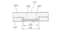
図7において、図5と共通する構造は符号を流用して詳細な説明を省略する。主たる変更点は、第1部材に凹部を設けたことである。
第2部材20Cに、第1部材10C側へ突出する円柱状の第2凸部120が一体的に設けられている。第2凸部120の外径をD3とする。In FIG. 7, the same reference numerals are used for structures common to those in FIG. 5, and detailed description thereof is omitted. The main change is that a recess is provided in the first member.
A columnar second
一方、第1部材10Cに、第2部材20C側に開口する第1凹部130が一体的に設けられている。この第1凹部130は、ピン(図6、符号51)で撹拌された第2部材20Cの第2凸部120が流入する部位である。また、第1凹部130の内径D4は、第2凸部120の外径D3よりも大径である。なお、第1凹部130は、平面視にて円形である。
加えて、第1凹部130に対応する第2部材20Cのツール側面に、接合終端部110が設けられている。On the other hand, the 1st recessed
In addition, a joining
以上に述べた第1部材10C及び第2部材20Cに施す摩擦撹拌接合法を次に述べる。
図8において、(a)に示されるように、矢印(12)のように回転している接合ツール50のピン51が第2部材20Cに挿入されている。回転中のピン51は、第2部材20Cに接触するので、摩擦熱が生じる。この摩擦熱で、ピン51周辺の第2部材20Cが軟化する。接合ツール50を矢印(13)のように相対的に移動させる。Next, the friction stir welding method applied to the
In FIG. 8, as shown in FIG. 8A, the
(b)に示されるように、接合ツール50が接合終端部110に移動し、ピン51で撹拌された第2部材20Cの第2凸部120が第1凹部130を埋めている。次に接合終端部110で矢印(14)のようにピン51を抜く。
(c)に示されるように、軟化した第2部材20Cが固化すると、第2部材20Cに、ピン51の体積分に相当するピン跡凹み131が形成される。また、第1部材10Cに第2部材20Cが接合されて摩擦撹拌接合材70Cが得られる。132は接合部である。As shown in (b), the joining
As shown in (c), when the softened
(a)において、第1部材10Cに、第2部材20C側に開口する第1凹部130が一体的に設けられている。この第1凹部130に対応する第2部材20Cの対応部位に、接合終端部110が設けられている。接合ツール50のピン51が接合終了時に接合終端部110に到達すると、接合終端部110の周辺材料は、ピン51と接合終端部110の間に生じる摩擦熱で軟化する。軟化した接合終端部110の周辺材料が回転しているピン51に撹拌され、第1凹部130に流入することで、(b)に示されるように接合終端部110の周辺材料は第1凹部130に充填される。充填後、固化した接合終端部110の周辺材料は、第1凹部130に接合され且つ嵌っている突起部であり、接合終端部110の周辺材料が第1凹部130に嵌合することになる。したがって、第1部材10Cに第2部材20Cが接合されることに加えて、接合終端部110の周辺材料が第1凹部130に嵌合することで、第1部材10Cに対する第2部材20Cの接合をより強化することができる。 In (a), the 1st recessed
さらに、(c)において、第2部材20Cの第2凸部120が、第1凹部130に充填されているので、第1部材10Cの外側にはみ出すことがない。第2凸部120のはみ出しがないので、接合後の外観が向上する。したがって、外観性に優れた摩擦撹拌接合材70Cを提供できる。 Furthermore, in (c), since the 2nd
上記第1部材10Cでは、第1凹部130を備えるようにした。この第1凹部130に第2部材20Cの第2凸部120が埋められることで、接合後の外観を向上させることができた。ところで、接合後の外観を向上させ、且つ摩擦撹拌接合材に掛かる加工費を低減できるとさらに好ましい。そこで、外観を向上させ、且つ加工費を低減できる例を次に説明する。 In the
図9において、図5と共通する構造は符号を流用して詳細な説明を省略する。主たる変更点は、第1部材に凹部を設け、第2部材から凸部を取り除いたことである。
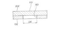
第1部材10Dに、第2部材20D側に開口する第1凹部140が一体的に設けられている。この第1凹部140は、ピン(図6、符号51)で撹拌された第2部材20Dの一部が流入する部位である。また、第1凹部140の内径をD5とする。なお、第1凹部140は、平面視にて円形である。In FIG. 9, the same reference numerals are used for structures common to those in FIG. 5, and detailed description thereof is omitted. The main change is that the concave portion is provided in the first member and the convex portion is removed from the second member.
A
第2部材20Dは、平板である。また、第1凹部140に対応する第2部材20Dのツール側面に、接合終端部110が設けられている。 The
以上に述べた第1部材10D及び第2部材20Dに施す摩擦撹拌接合法を次に述べる。
図10において、(a)に示されるように、矢印(15)のように回転している接合ツール50のピン51が第2部材20Dに挿入されている。回転中のピン51は、第2部材20Dに接触するので、摩擦熱が生じる。この摩擦熱で、ピン51周辺の第2部材20Dが軟化する。接合ツール50を矢印(16)のように相対的に移動させる。Next, the friction stir welding method applied to the
In FIG. 10, as shown in (a), the
(b)に示されるように、接合ツール50が接合終端部110に移動し、ピン51で撹拌された第2部材20Dの一部141が第1凹部140を埋めている。次に接合終端部110で矢印(17)のようにピン51を抜く。
(c)に示されるように、軟化した第2部材20Dが固化すると、第2部材20Dに、ピン51の体積分に相当するピン跡凹み142が形成される。また、第1部材10Dに第2部材20Dが接合されて摩擦撹拌接合材70Dが得られる。143は接合部である。As shown in (b), the joining
As shown in (c), when the softened
(a)において、第1部材10Dに第1凹部140を設け、第2部材20Dに加工を施していない。第1部材10Dにのみ加工したので、摩擦撹拌接合材70Dに掛かる加工費を低減することができる。また、第2部材20Dの一部141が第1凹部140で覆われるので、外観性が向上する。したがって、外観を向上させ、且つ加工費を低減できる摩擦撹拌接合材70Dを提供できる。 In (a), the
上記第1部材10Dでは、第1凹部140を備えるようにした。この第1凹部140に第2部材20Dの一部141が埋められることで、接合後の外観を向上させ、且つ加工費を低減させることができた。ところで、第1部材に施す加工がより簡単であれば、第1部材の製作費を更に低減させることができる。そこで、第1部材の製作費を更に低減できる例を次に説明する。 The
図11において、図5と共通する構造は符号を流用して詳細な説明を省略する。主たる変更点は、第1部材に穴部を設けたことである。
第1部材10Eに、第2部材20Eに開口する第1穴部150が設けられている。この第1穴部150の内径はD6である。なお、第1穴部150は、平面視にて円形である。
一方、第2部材20Eは、平板である。また、第1穴部150に対応する第2部材20Eのツール側面に、接合終端部110が設けられている。In FIG. 11, the structure common to FIG. The main change is that a hole is provided in the first member.
The
On the other hand, the
以上に述べた第1部材10E及び第2部材20Eに施す摩擦撹拌接合法を次に述べる。
図12において、(a)に示されるように、矢印(18)のように回転している接合ツール50のピン51が第2部材20Eに挿入されている。回転中のピン51は、第2部材20Eに接触するので、摩擦熱が生じる。この摩擦熱で、ピン51周辺の第2部材20Eが軟化する。接合ツール50を矢印(19)のように相対的に移動させる。Next, the friction stir welding method applied to the
In FIG. 12, as shown in (a), the
(b)に示されるように、接合ツール50が接合終端部110に移動し、ピン51で撹拌された第2部材20Eの一部151が第1穴部150を埋めている。次に接合終端部110で矢印(20)のようにピン51を抜く。
(c)に示されるように、軟化した第2部材20Eが固化すると、第2部材20Eに、ピン51の体積分に相当するピン跡凹み152が形成される。また、第1部材10Eに第2部材20Eが接合されて摩擦撹拌接合材70Eが得られる。153は接合部である。As shown in (b), the joining
As shown in (c), when the softened
(a)において、第1部材10Eに第1穴部150を設け、第2部材20Eに加工を施していない。第1穴部150は、第1部材10Eに穴を開けるだけよいから、加工がより簡単である。加工がより簡単であると、加工時間が短くて済むので、第1部材の製作費を更に低減できる。 In (a), the
ところで、図9において、第1部材10Dには、凹部140が形成されている。この凹部140の加工時間が短縮できれば、第1部材10Dに対する摩擦撹拌接合が迅速に実施でき、摩擦撹拌接合材の量産能力が高まることが期待される。そこで、より量産性に適した形態の第1部材の例を次に説明する。 Incidentally, in FIG. 9, a
図13でより量産性に適する形態の第1部材を説明する。
図13において、図9と共通する構造は符号を流用して詳細な説明を省略する。図9との主たる変更点は、第1部材にプレス加工を施して凹部を形成したことである。The first member in a form more suitable for mass productivity will be described with reference to FIG.
In FIG. 13, the same reference numerals are used for structures common to those in FIG. 9, and detailed description thereof is omitted. The main change from FIG. 9 is that the first member is pressed to form a recess.
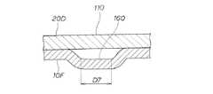
第1部材10Fに、第2部材20D側に開口する第1凹部160が一体的に設けられている。この第1凹部160は、第1部材10Fにプレス加工を施すことにより形成される。加えて、第1凹部160は、ピン(図6、符号51)で撹拌された第2部材20Dの一部が流入する部位である。さらに、第1凹部160の底部内径をD7とする。なお、第1凹部160は、平面視にて円形である。 A
以上に述べた第1部材10F及び第2部材20Dに施す摩擦撹拌接合法を次に述べる。
図14において、(a)に示されるように、矢印(21)のように回転している接合ツール50のピン51が第2部材20Dに挿入されている。回転中のピン51は、第2部材20Dに接触するので、摩擦熱が生じる。この摩擦熱で、ピン51周辺の第2部材20Dが軟化する。接合ツール50を矢印(22)のように相対的に移動させる。Next, the friction stir welding method applied to the
In FIG. 14, as shown in (a), the
(b)に示されるように、接合ツール50が接合終端部110に移動し、ピン51で撹拌された第2部材20Dの一部161が第1凹部160を埋めている。次に接合終端部110で矢印(23)のようにピン51を抜く。
(c)に示されるように、軟化した第2部材20Dが固化すると、第2部材20Dに、ピン51の体積分に相当するピン跡凹み162が形成される。また、第1部材10Fに第2部材20Dが接合されて摩擦撹拌接合材70Fが得られる。163は接合部である。As shown in (b), the joining
As shown in (c), when the softened
(a)において、第1部材10Fにプレス加工を施して第1凹部160を形成した。プレス加工は一般に機械加工に比べて加工時間が短いため、第1部材10Fを摩擦撹拌接合工程に円滑に供給でき、第1部材10Fに対する摩擦撹拌接合が迅速に実施できる。第1部材10Fを用いることで、摩擦撹拌接合材70Fの量産能力が高まることが期待される。 In (a), the
尚、本発明に係る第1部材に鋼板が好適であり、第2部材にアルミニウム板が好適である。第2部材に、アルミニウム板の代わりにマグネシウム板を適用してもよい。
加えて、本発明に係る凸部は、実施の形態では円柱状としたが、角柱状や楕円柱状であってもよい。
さらに、本発明に係る凹部は、実施の形態では平面視にて円状としたが、角状や楕円状であってもよい。In addition, a steel plate is suitable for the 1st member which concerns on this invention, and an aluminum plate is suitable for the 2nd member. A magnesium plate may be applied to the second member instead of the aluminum plate.
In addition, although the convex portion according to the present invention has a cylindrical shape in the embodiment, it may have a prismatic shape or an elliptical column shape.
Furthermore, although the recessed part which concerns on this invention was made into circular shape by planar view in embodiment, square shape and elliptical shape may be sufficient.
本発明の摩擦撹拌接合材の製造方法は、自動車の車体構成部品に好適である。Themethod for producing a friction stir welding materialof the present invention is suitable for vehicle body components.
10A、10D…第1部材、20A、20D…第2部材、21…一端、22…他端、30…凸部、40、110…接合終端部、50…接合ツール、51…ピン、70A、70D…摩擦撹拌接合材、140…凹部、141…一部、h1…ピンの長さ。 10A, 10D ... first member, 20A, 20D ... second member, 21 ... one end, 22 ... other end, 30 ... convex part, 40,110 ... joining termination part, 50 ... joining tool, 51 ... pin, 70A, 70D ... Friction stir welding material, 140 ... concave part, 141 ... part, h1 ... pin length.
Claims (2)
Translated fromJapanese前記第2部材のうち接合終端部には、
一般接合面よりも前記接合ツール側へ突出する凸部が一体的に設けられ、
前記凸部は、前記ピンの長さより高く形成されている、
ことを特徴とする摩擦撹拌接合材の製造方法。A second member made of a material different from that of the first member is stacked on the first member, a pin of a friction stir welding method welding tool is inserted into the second member, and welding is started from one end of the second member. Amethod of manufacturing a friction stir welding material obtained by joining the second member to the first member by pulling out the pin at the joining terminal portion before reaching the end,
Of the second member, the joining end portion is
A convex portion that protrudes toward the joining tool side from the general joining surface is integrally provided,
The convex portion is formed higher than the length of the pin.
Amethod for producing a friction stir welding material, comprising:
前記第2部材の一端から接合を始め、
他端に到達する前の接合終端部で前記ピンを抜くことにより、前記第1部材に前記第2部材を接合してなる摩擦撹拌接合材の製造方法であって、
前記第1部材の接合終端部には、前記第2部材側に開口する凹部が一体に設けられ、
前記凹部には前記第2部材の一部が流入し、前記第2部材には前記凹部側に突出する凸部が形成され、
前記接合端部において、前記ピンが前記第1部材に当接することなく引き抜かれている、
ことを特徴とする摩擦撹拌接合材の製造方法。A second member made of a material different from that of the first member is stacked on the first member, and a pin of a friction stir welding method welding tool is inserted into the second member, and the pin contacts the surface of the first member. While rotating,
Start joining from one end of the second member,
Amethod of manufacturing a friction stir welding material obtained by joining the second member to the first member by pulling out the pin at the joining terminal portion before reaching the other end,
A concave portion that opens to the second member side is integrally provided at the joining end portion of the first member,
A portion of the second member flows into the concave portion, and a convex portion that protrudes toward the concave portion is formed on the second member.
In the joint end, the pin is pulled out without coming into contact withthe first member ,
Amethod for producing a friction stir welding material, comprising:
Priority Applications (3)
| Application Number | Priority Date | Filing Date | Title |
|---|---|---|---|
| JP2011212241AJP5843547B2 (en) | 2010-12-24 | 2011-09-28 | Method of manufacturing friction stir welding material |
| US13/442,832US9616520B2 (en) | 2010-12-24 | 2012-04-09 | Friction stir welding member |
| CN201210202474.5ACN103028837B (en) | 2010-12-24 | 2012-06-15 | Attachment are stirred in friction |
Applications Claiming Priority (3)
| Application Number | Priority Date | Filing Date | Title |
|---|---|---|---|
| JP2010288233 | 2010-12-24 | ||
| JP2010288233 | 2010-12-24 | ||
| JP2011212241AJP5843547B2 (en) | 2010-12-24 | 2011-09-28 | Method of manufacturing friction stir welding material |
Publications (2)
| Publication Number | Publication Date |
|---|---|
| JP2012143812A JP2012143812A (en) | 2012-08-02 |
| JP5843547B2true JP5843547B2 (en) | 2016-01-13 |
Family
ID=46787923
Family Applications (1)
| Application Number | Title | Priority Date | Filing Date |
|---|---|---|---|
| JP2011212241AActiveJP5843547B2 (en) | 2010-12-24 | 2011-09-28 | Method of manufacturing friction stir welding material |
Country Status (3)
| Country | Link |
|---|---|
| US (1) | US9616520B2 (en) |
| JP (1) | JP5843547B2 (en) |
| CN (1) | CN103028837B (en) |
Families Citing this family (8)
| Publication number | Priority date | Publication date | Assignee | Title |
|---|---|---|---|---|
| EP3053697B1 (en)* | 2013-09-30 | 2017-11-08 | JFE Steel Corporation | Friction stir welding method for steel sheets |
| JP6300077B2 (en)* | 2014-02-18 | 2018-03-28 | スズキ株式会社 | Friction stir welding method and friction stir welded body |
| JP6212028B2 (en)* | 2014-12-26 | 2017-10-11 | トヨタ自動車株式会社 | Point friction stir welding structure |
| JP6006822B2 (en)* | 2015-03-19 | 2016-10-12 | 富士重工業株式会社 | Resin member |
| EP3178600A1 (en)* | 2015-12-11 | 2017-06-14 | Lortek S. Coop. | Method for welding together dissimilar parts |
| JP6410756B2 (en) | 2016-05-17 | 2018-10-24 | 本田技研工業株式会社 | Metal composite and metal joining method |
| CN107755876B (en)* | 2016-08-23 | 2021-01-01 | 苹果公司 | Joining components having different structural compositions by friction stir welding |
| FR3141359B1 (en)* | 2022-10-28 | 2024-10-25 | Safran Nacelles | Friction stir welding process and associated welding assembly |
Family Cites Families (15)
| Publication number | Priority date | Publication date | Assignee | Title |
|---|---|---|---|---|
| JP3763734B2 (en)* | 2000-10-27 | 2006-04-05 | 株式会社日立製作所 | Panel member processing method |
| JP3553012B2 (en)* | 2000-11-17 | 2004-08-11 | 株式会社日立製作所 | Friction stir welding method |
| JP4629241B2 (en)* | 2001-01-23 | 2011-02-09 | 昭和電工株式会社 | Termination part treatment method in friction stir welding and termination part treated friction stir welded body |
| JP2003170280A (en)* | 2001-12-04 | 2003-06-17 | Nippon Steel Corp | Dissimilar metal materials joining method |
| JP2004106037A (en)* | 2002-09-20 | 2004-04-08 | Hitachi Ltd | How to join metal materials |
| JP2004141898A (en)* | 2002-10-23 | 2004-05-20 | Hitachi Ltd | Friction stir welding method and apparatus |
| JP2005034864A (en)* | 2003-07-18 | 2005-02-10 | Mitsubishi Heavy Ind Ltd | Friction stir welding method |
| US7367487B2 (en)* | 2003-08-22 | 2008-05-06 | Honda Motor Co., Ltd. | Method for friction stir welding, jig therefor, member with friction stir-welded portion, and tool for friction stir welding |
| JP4148152B2 (en)* | 2004-02-16 | 2008-09-10 | マツダ株式会社 | Friction spot joint structure |
| JP4602796B2 (en)* | 2005-03-02 | 2010-12-22 | 住友軽金属工業株式会社 | Dissimilar metal member joining method |
| JP2007301573A (en)* | 2006-05-08 | 2007-11-22 | Honda Motor Co Ltd | Friction stir welding method and friction stir welding structure |
| CN102267006B (en)* | 2006-10-02 | 2016-08-03 | 日本轻金属株式会社 | Joint method |
| CN103551722A (en)* | 2008-02-21 | 2014-02-05 | 日本轻金属株式会社 | Method of manufacturing heat transfer plate |
| US7762447B2 (en)* | 2008-03-20 | 2010-07-27 | Ut-Battelle, Llc | Multiple pass and multiple layer friction stir welding and material enhancement processes |
| CN102085537B (en)* | 2009-12-03 | 2013-11-06 | 鸿富锦精密工业(深圳)有限公司 | Friction stirring forming method |
- 2011
- 2011-09-28JPJP2011212241Apatent/JP5843547B2/enactiveActive
- 2012
- 2012-04-09USUS13/442,832patent/US9616520B2/enactiveActive
- 2012-06-15CNCN201210202474.5Apatent/CN103028837B/enactiveActive
Also Published As
| Publication number | Publication date |
|---|---|
| JP2012143812A (en) | 2012-08-02 |
| US20130078429A1 (en) | 2013-03-28 |
| US9616520B2 (en) | 2017-04-11 |
| CN103028837A (en) | 2013-04-10 |
| CN103028837B (en) | 2016-05-11 |
Similar Documents
| Publication | Publication Date | Title |
|---|---|---|
| JP5843547B2 (en) | Method of manufacturing friction stir welding material | |
| JP5572350B2 (en) | Wire ultrasonic bonding method | |
| JP2012128976A (en) | Wire connection structure of connector terminal and manufacturing method thereof | |
| JP2011044423A (en) | Crimping terminal fitting and wire with terminal fitting | |
| JP5276817B2 (en) | Metal bonded body, metal bonding method, and metal bonding apparatus | |
| JP5719505B2 (en) | Metal bonding equipment | |
| JP6320856B2 (en) | Manufacturing method of laminated iron core | |
| JP2019204588A (en) | Terminal-equipped electric wire and manufacturing method thereof | |
| KR100874697B1 (en) | One-Piece-shaped 3-Dimensional Bezel Structure and Manufacturing Method | |
| JP2012114238A (en) | Lead frame for electronic component and manufacturing method of the same | |
| JP2008238252A (en) | Manufacturing method of aluminum alloy casing and casing manufactured by the manufacturing method | |
| JP5168440B2 (en) | Driving part fastening method and driving part | |
| JP2017152346A (en) | Electric wire with terminal | |
| JP2010220282A (en) | Method of assembling the end cover of motor | |
| JP4699736B2 (en) | Method for winding plate members | |
| JP2005041119A (en) | Resin insert molding jig for metal plate member and resin insert molding method for metal plate member using the same | |
| JP2000013048A (en) | Manufacturing method of electronic device and housing for electronic device, punching device | |
| JP5093131B2 (en) | Manufacturing method of rivet terminal | |
| JP5889547B2 (en) | Metal joint | |
| JP2012043872A (en) | Electronic component and method for manufacturing the same | |
| WO2017068965A1 (en) | Production method for terminal-equipped electrical wire, crimp tool, and terminal-equipped electrical wire | |
| JP2007103400A (en) | Lower face electrode-type solid electrolytic capacitor | |
| JP2006054218A (en) | Electric equipment | |
| JP2006114272A (en) | Electrical component and manufacturing method thereof | |
| JP5167543B2 (en) | Lead frame with heat sink and manufacturing method thereof |
Legal Events
| Date | Code | Title | Description |
|---|---|---|---|
| A621 | Written request for application examination | Free format text:JAPANESE INTERMEDIATE CODE: A621 Effective date:20131128 | |
| A977 | Report on retrieval | Free format text:JAPANESE INTERMEDIATE CODE: A971007 Effective date:20141006 | |
| A131 | Notification of reasons for refusal | Free format text:JAPANESE INTERMEDIATE CODE: A131 Effective date:20141111 | |
| A521 | Written amendment | Free format text:JAPANESE INTERMEDIATE CODE: A523 Effective date:20150108 | |
| A131 | Notification of reasons for refusal | Free format text:JAPANESE INTERMEDIATE CODE: A131 Effective date:20150714 | |
| A521 | Written amendment | Free format text:JAPANESE INTERMEDIATE CODE: A523 Effective date:20150907 | |
| TRDD | Decision of grant or rejection written | ||
| A01 | Written decision to grant a patent or to grant a registration (utility model) | Free format text:JAPANESE INTERMEDIATE CODE: A01 Effective date:20151110 | |
| A61 | First payment of annual fees (during grant procedure) | Free format text:JAPANESE INTERMEDIATE CODE: A61 Effective date:20151117 | |
| R150 | Certificate of patent or registration of utility model | Ref document number:5843547 Country of ref document:JP Free format text:JAPANESE INTERMEDIATE CODE: R150 | |
| R250 | Receipt of annual fees | Free format text:JAPANESE INTERMEDIATE CODE: R250 |