JP5843263B2 - Guide wire gripper - Google Patents
Guide wire gripperDownload PDFInfo
- Publication number
- JP5843263B2 JP5843263B2JP2012029448AJP2012029448AJP5843263B2JP 5843263 B2JP5843263 B2JP 5843263B2JP 2012029448 AJP2012029448 AJP 2012029448AJP 2012029448 AJP2012029448 AJP 2012029448AJP 5843263 B2JP5843263 B2JP 5843263B2
- Authority
- JP
- Japan
- Prior art keywords
- guide wire
- gripping tool
- outer cylinder
- cylinder
- stopper
- Prior art date
- Legal status (The legal status is an assumption and is not a legal conclusion. Google has not performed a legal analysis and makes no representation as to the accuracy of the status listed.)
- Active
Links
Images


Classifications
- A—HUMAN NECESSITIES
- A61—MEDICAL OR VETERINARY SCIENCE; HYGIENE
- A61M—DEVICES FOR INTRODUCING MEDIA INTO, OR ONTO, THE BODY; DEVICES FOR TRANSDUCING BODY MEDIA OR FOR TAKING MEDIA FROM THE BODY; DEVICES FOR PRODUCING OR ENDING SLEEP OR STUPOR
- A61M25/00—Catheters; Hollow probes
- A61M25/01—Introducing, guiding, advancing, emplacing or holding catheters
- A61M25/09—Guide wires
- A61M2025/09116—Design of handles or shafts or gripping surfaces thereof for manipulating guide wires
Landscapes
- Media Introduction/Drainage Providing Device (AREA)
Description
Translated fromJapanese本発明は、ガイドワイヤに取り付けて使用するガイドワイヤ用把持具に関する。 The present invention relates to a guide wire gripping tool used by being attached to a guide wire.
従来、経皮的冠動脈形成術等の血管内治療に使用される医療用機械器具の一つとして、バルーンカテーテルやステント等のデバイスを病変部まで導くために使用されるガイドワイヤが知られている。 Conventionally, a guide wire used for guiding a device such as a balloon catheter or a stent to a lesion site is known as one of medical instruments used for endovascular treatment such as percutaneous coronary angioplasty. .
ガイドワイヤは、一般的には、近位部及び遠位部を有する長尺かつ細径のコアシャフトと、コアシャフトの遠位部が内部に挿入されるコイルと、コアシャフト及びコイルを固定するロウ付け部とから形成されている。
ガイドワイヤの遠位部は体内に挿入されることにより病変部に到達し、ガイドワイヤの近位部は医師等の手技者によって回転操作や押引操作される。The guide wire generally has a long and thin core shaft having a proximal portion and a distal portion, a coil into which the distal portion of the core shaft is inserted, and the core shaft and the coil are fixed. And a brazing portion.
The distal portion of the guide wire reaches the lesioned portion by being inserted into the body, and the proximal portion of the guide wire is rotated or pushed / pulled by an operator such as a doctor.
ガイドワイヤを手技者が操作する際には、ガイドワイヤが細径であるので、ガイドワイヤの近位部を手技者が直接把持して操作することはあまりなく、多くの場合、ガイドワイヤの近位部に取り付けられたガイドワイヤ用把持具を手技者が把持して操作する。 When the operator operates the guide wire, since the guide wire is small in diameter, the operator does not often operate by directly grasping the proximal portion of the guide wire. The operator grips and operates the guide wire gripping tool attached to the position portion.
このような従来のガイドワイヤ用把持具としては、例えば、円筒把持部とキャップとチャックとからなる特許文献1に開示されたガイドワイヤ用把持具が知られている(特許文献1参照)。 As such a conventional guide wire gripping tool, for example, a guide wire gripping tool disclosed in Patent Literature 1 including a cylindrical gripping portion, a cap, and a chuck is known (see Patent Literature 1).
図5(a)は、従来のガイドワイヤ用把持具の平面図であり、図5(b)は、図5(a)に示すガイドワイヤ用把持具を長手方向に沿って切断した断面図であり、図5(c)は、図5(a)に示すガイドワイヤ用把持具の分解斜視図である。 FIG. 5A is a plan view of a conventional guide wire gripping tool, and FIG. 5B is a cross-sectional view of the guide wire gripping tool shown in FIG. 5A cut along the longitudinal direction. FIG. 5 (c) is an exploded perspective view of the guide wire gripping tool shown in FIG. 5 (a).
図5(a)〜図5(c)に示す従来のガイドワイヤ用把持具100は、貫通孔210及び先端の外側面に形成された雄ネジ部220を有する円筒把持部200と、貫通孔210に連通した他の貫通孔310、後端の内側面に形成されており雄ネジ部220に螺合する雌ネジ部320及び先端の内側面に形成されたテーパー部330を有するキャップ300と、ガイドワイヤ貫通孔410、貫通孔210に挿入される管状部420及び管状部420の先端に形成されており別の貫通孔310に挿入される頭部430を有するチャック400と、から形成されている。
また、チャック400の頭部430には、チャック400の長軸方向に沿って複数の縦溝440が形成されており、頭部430の半径方向外側から半径方向内側に向かって外力が加えられると、頭部430に形成されたガイドワイヤ貫通孔410(縦溝440)が閉じられるように動作する。The conventional guide
A plurality of
従来のガイドワイヤ用把持具100を使用してガイドワイヤGを把持する場合には、次のようにして行う。
まず、円筒把持部200の貫通孔210にチャック400の管状部420を挿入し、キャップ300の貫通孔310にチャック400の頭部430が挿入されるようにしてキャップ300をチャック400の頭部430に被せる。
そして、円筒把持部200の雄ネジ部220とキャップ300の雌ネジ部320とを軽く螺合させて、仮組み立てする。
次に、ガイドワイヤGの一端をキャップ300の貫通孔310から、チャック400のガイドワイヤ貫通孔410及び円筒把持部200の貫通孔210まで挿入する。
この状態から円筒把持部200の雄ネジ部220とキャップ300の雌ネジ部320とをさらに螺合していくと、キャップ300のテーパー部330がチャック400の頭部430を半径方向外側から半径方向内側に向かって締め付けていき、頭部430に形成されたガイドワイヤ貫通孔410(縦溝440)が閉じられていく。
このようにして、ガイドワイヤGが頭部430によって固定される。When the guide wire G is gripped using the conventional guide
First, the
Then, the male threaded
Next, one end of the guide wire G is inserted from the through
When the
In this way, the guide wire G is fixed by the head 430.
なお、ガイドワイヤとは構成が相違し、それに起因して用途及び機能も全く異なる医療用機械器具であるカテーテルを把持するためのカテーテル用把持具としては、例えば、特許文献2に開示されたカテーテル用把持具が知られている。 In addition, as a catheter gripping tool for gripping a catheter which is a medical machine instrument having a configuration different from that of a guide wire and resulting in completely different uses and functions, for example, a catheter disclosed in
特許文献1に記載された従来のガイドワイヤ用把持具は、以下の問題がある。 The conventional guide wire gripping tool described in Patent Document 1 has the following problems.
ガイドワイヤの遠位部が病変部等によりスタックした場合、手技者は、ガイドワイヤ用把持具を把持してガイドワイヤを手元に引っ張ることによりスタックからの脱出を図ることがある。 When the distal portion of the guide wire is stacked due to a lesion or the like, the operator may attempt to escape from the stack by holding the guide wire gripping tool and pulling the guide wire toward the hand.
しかし、ガイドワイヤの近位部はガイドワイヤ用把持具のチャックにより固定されているため、ガイドワイヤ用把持具を手技者が強く引張すぎてガイドワイヤの引張破断荷重以上の引張力がガイドワイヤに加えられた場合には、ガイドワイヤが破断してしまう。
そして、ガイドワイヤの破断位置によっては、破断したガイドワイヤの体内留置が生じるという問題がある。However, since the proximal portion of the guide wire is fixed by the chuck of the guide wire gripping tool, the operator pulls the guide wire gripping tool too strongly, and the tensile force exceeding the tensile breaking load of the guide wire is applied to the guide wire. If added, the guidewire will break.
And depending on the breaking position of a guide wire, there exists a problem that the indwelling of the broken guide wire arises.
本発明のガイドワイヤ用把持具は、先端部、後端部、内側面により区画された第一中空軸及び前記第一中空軸に通されるガイドワイヤが固定される固定部を有する内筒体と、前記先端部側に位置する遠位部、前記後端部側に位置する近位部及び前記内筒体が挿入される第二中空軸を有する外筒体と、前記外筒体が接触するように形成されたストッパと、前記内筒体及び前記ストッパを係合する係合手段とを備え、前記係合手段は、所定の引張力が前記外筒体に加えられた際に、前記内筒体と前記ストッパとの係合が解除されるように形成されていることを特徴とする。
なお、本明細書において、所定の引張力とは、その上限値がガイドワイヤの引張破断荷重未満である荷重のことをいい、例えば、ガイドワイヤの引張破断荷重が2.0〜20N(0.2〜2.0kgf)である場合には、所定の引張力の上限値は2.0〜20N(0.2〜2.0kgf)未満である。下限値については特に限定されないが、あまり低い値に設定すると振動が加えられること等により係合が解除されて外筒体が脱落しやすくなってしまうので、上限値からあまり離れていないことが望ましい。A guide wire gripping tool according to the present invention includes an inner cylinder having a first hollow shaft defined by a front end portion, a rear end portion, and an inner surface, and a fixing portion to which a guide wire passed through the first hollow shaft is fixed. An outer cylinder having a distal portion located on the tip end side, a proximal portion located on the rear end side, and a second hollow shaft into which the inner cylinder is inserted, and theouter cylinder in contact with each other a stopper formed tocomprisean engaging means for engagingsaid inner tubular member andthestopper, the engagement means, when a predetermined tensile force is applied to the outer cylindricalbody, the It is formed so that the engagement between the inner cylinder and thestopper is released.
In the present specification, the predetermined tensile force refers to a load whose upper limit is less than the tensile breaking load of the guide wire. For example, the tensile breaking load of the guide wire is 2.0 to 20 N (0. 2 to 2.0 kgf), the upper limit value of the predetermined tensile force is 2.0 to 20 N (0.2 to 2.0 kgf). The lower limit value is not particularly limited, but if it is set to a very low value, the engagement is released due to vibrations and the like, and the outer cylinder is likely to fall off. .
本発明のガイドワイヤ用把持具において、内筒体と外筒体とを直接的又は間接的に係合する係合手段は、所定の引張力が外筒体に加えられた際に内筒体と外筒体との係合が解除されるように形成されているので、ガイドワイヤの遠位部が病変部によりスタックした場合等であっても、ガイドワイヤの引張による破断を防止することができる。
このことについて、以下に図面を用いて説明する。In the guide wire gripping tool of the present invention, the engaging means for directly or indirectly engaging the inner cylinder and the outer cylinder is the inner cylinder when a predetermined tensile force is applied to the outer cylinder. Since the engagement between the guide wire and the outer cylinder is released, even when the distal portion of the guide wire is stuck by the lesioned portion, it is possible to prevent the guide wire from being broken by pulling. it can.
This will be described below with reference to the drawings.
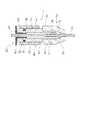
図1(a)は、本発明の第一実施形態に係るガイドワイヤ用把持具を模式的に示す平面図であり、図1(b)は、図1(a)に示すガイドワイヤ用把持具を長手方向に沿って切断した断面図であり、図1(c)は、図1(a)に示すガイドワイヤ用把持具の分解斜視図である。 FIG. 1A is a plan view schematically showing a guide wire gripping tool according to the first embodiment of the present invention, and FIG. 1B is a guide wire gripping tool shown in FIG. FIG. 1C is an exploded perspective view of the guide wire gripping tool shown in FIG. 1A.
図1(a)〜図1(c)に示す本発明のガイドワイヤ用把持具1は、先端部11、後端部12、内側面13により区画された第一中空軸及び第一中空軸に通されるガイドワイヤGが固定される固定部14を有する内筒体10と、先端部11側に位置する遠位部31、後端部12側に位置する近位部32及び内筒体10が挿入された第二中空軸を有する外筒体30と、内筒体10及び外筒体30を直接的又は間接的に係合する係合手段40と、からなる。 The guide wire gripping tool 1 of the present invention shown in FIGS. 1A to 1C includes a first hollow shaft and a first hollow shaft defined by a
係合手段40は、内筒体10の外側面に形成された凸状部41と凸状部41に嵌合可能なように外筒体30の内側面33に形成された凹状部42とからなり、凸状部41及び凹状部42は、所定の引張力が外筒体30に加えられた際に内筒体10と外筒体30との係合が解除されるように形成されている。
そのため、医師等の手技者が所定の引張力をもって外筒体30を手元側に引っ張った場合には、係合手段40による内筒体10と外筒体30との係合が解除されることにより、ガイドワイヤGが固定された内筒体10から外筒体30が離脱する。
なお、図1(a)〜図1(c)では、凸状部及び凹状部から係合手段が形成された実施形態を示しているが、本発明のガイドワイヤ用把持具に係る係合手段としては、凸状部及び凹状部に限定されず、後述する各実施形態に記載した構成を適宜採用し得る。The
Therefore, when an operator such as a doctor pulls the
1 (a) to 1 (c) show an embodiment in which the engaging means is formed from the convex portion and the concave portion, the engaging means according to the guide wire gripping tool of the present invention. As, it is not limited to a convex part and a concave part, The structure described in each embodiment mentioned later can be employ | adopted suitably.
係る構成を有するカイドワイヤ用把持具1でガイドワイヤGを固定し、これを用いて血管内治療を行う場合には、内筒体10及び/又は外筒体30を把持して押引したり、回転したりすることにより、ガイドワイヤGを押引操作したり、回転操作したりすることができる。 When the guide wire G is fixed with the guide 1 for the guide wire having such a configuration and endovascular treatment is performed using the guide wire G, the
ここで、ガイドワイヤGの遠位部が病変部でスタック等した場合、所定の引張力よりも小さい引張力でガイドワイヤ用把持具1の外筒体30を手技者が手元側に引っ張ると、係合手段40を介して外筒体30に係合した内筒体10が手元側に引っ張られ、その結果、ガイドワイヤGも手元側に引っ張られる。これにより、ガイドワイヤGがスタックから脱出できることがある。 Here, when the distal portion of the guide wire G is stuck at the lesion portion, when the operator pulls the
一方、スタックからなかなか脱出できない場合でも、手技者はガイドワイヤGの引張による破断を恐れずに、外筒体30を引っ張ることができる。
外筒体30を強く引張すぎたとしても、所定の引張力が外筒体30に加えられた際に内筒体10と外筒体30との係合が解除されるように係合手段40が形成されているので、ガイドワイヤGに引張破断荷重以上の荷重が負荷されて引張により破断するよりも先に、係合手段40による係合が解除されて内筒体10から外筒体30が手元側に離脱し、ガイドワイヤGに引張力が加えられなくなるからである。On the other hand, even when it is difficult to escape from the stack, the operator can pull the
Even if the
このように、本発明のガイドワイヤ用把持具1は、ガイドワイヤGに取り付けて使用することにより、ガイドワイヤGの引張による破断を防止することができる。 Thus, the guide wire gripping tool 1 of the present invention can be prevented from being broken by pulling the guide wire G when used by being attached to the guide wire G.
本発明のガイドワイヤ用把持具は、前記外筒体が接触するように形成されたストッパをさらに備えており、前記係合手段は、前記内筒体及び前記ストッパに形成されていることが望ましい。 The guide wire gripping tool of the present invention preferably further includes a stopper formed so that the outer cylindrical body comes into contact, and the engaging means is preferably formed on the inner cylindrical body and the stopper. .
本発明のガイドワイヤ用把持具において、前記係合手段は、前記内筒体に形成された凹状部と、前記凹状部に嵌合可能なように前記ストッパに形成された凸状部と、前記凹状部が形成された位置よりも前記内筒体の前記後端部側の位置に前記凸状部が嵌合可能なように形成された別の凹状部と、からなることが望ましい。 In the guide wire gripping tool of the present invention, the engaging means includes a concave portion formed in the inner cylindrical body, a convex portion formed in the stopper so as to be engageable with the concave portion, It is desirable to comprise another concave portion formed so that the convex portion can be fitted to a position on the rear end side of the inner cylindrical body rather than a position where the concave portion is formed.
本発明のガイドワイヤ用把持具において、前記内筒体と前記外筒体とは、前記第一中空軸及び前記第二中空軸を回転軸として互いに回転可能に形成されており、前記内筒体の外側面には、第一突起部が形成されており、前記外筒体の内側面には、前記第一突起部に接触する第二突起部が形成されており、前記第一突起部と前記第二突起部とは、前記外筒体を回転させることにより所定の回転力が加えられた際に、前記第二突起部が前記第一突起部を乗り越えて前記第二突起部と前記第一突起部との接触が解除されるように形成されていることが望ましい。 In the guide wire gripping tool of the present invention, the inner cylindrical body and the outer cylindrical body are formed to be rotatable with respect to each other about the first hollow shaft and the second hollow shaft, and the inner cylindrical body A first protrusion is formed on the outer surface of the outer cylinder, and a second protrusion that contacts the first protrusion is formed on the inner surface of the outer cylindrical body. The second projecting portion means that when a predetermined rotational force is applied by rotating the outer cylinder, the second projecting portion gets over the first projecting portion and the second projecting portion and the second projecting portion. It is desirable that the contact with the one protrusion is released.
(第一実施形態)
本発明の第一実施形態に係るガイドワイヤ用把持具1について、図1(a)〜図1(c)を参照しつつ説明する。
なお、第一実施形態に係るガイドワイヤ用把持具は、上述した本発明のガイドワイヤ把持具と略同一の構成を有しているので、重複する事項の説明は省略することもある。(First embodiment)
A guide wire gripping tool 1 according to a first embodiment of the present invention will be described with reference to FIGS. 1 (a) to 1 (c).
Note that the guide wire gripping tool according to the first embodiment has substantially the same configuration as the above-described guide wire gripping tool of the present invention, and therefore description of overlapping items may be omitted.
第一実施形態に係るガイドワイヤ用把持具1は、先端部11、後端部12、内側面13により区画された第一中空軸及び第一中空軸に通されるガイドワイヤGが固定される固定部14を有する内筒体10と、先端部11側に位置する遠位部31、後端部12側に位置する近位部32及び内筒体10が挿入された第二中空軸を有する外筒体30と、内筒体10及び外筒体30を直接的に係合する係合手段40と、からなる。 In the guide wire gripping tool 1 according to the first embodiment, a first hollow shaft defined by a
係合手段40は、内筒体10の外側面に形成された凸状部41と凸状部41に嵌合可能なように外筒体30の内側面33に形成された凹状部42とからなり、凸状部41及び凹状部42は、所定の引張力が外筒体30に加えられた際に内筒体10と外筒体30との係合が解除されるように形成されている。
従って、既に説明したとおり、第一実施形態のガイドワイヤ用把持具1は、ガイドワイヤGに取り付けて使用することにより、ガイドワイヤGの引張による破断を防止することができる。The engaging means 40 includes a
Therefore, as already explained, the guide wire gripping tool 1 according to the first embodiment can be used by being attached to the guide wire G to prevent breakage of the guide wire G due to tension.
凸状部41及び凹状部42の詳細な凹凸形状については特に限定されないが、例えば、引張試験機のチャックで内筒体10と外筒体30とを把持しておいて、ガイドワイヤGの引張破断荷重未満の引張力を加えた際に内筒体10から外筒体30が離脱するように、凸状部41及び凹状部42の材質等を考慮しながら凹凸形状(凹状部の窪み具合、凸状部の突出具合)等を適宜変更することで決めればよい。 The detailed uneven shapes of the
内筒体10は、筒部17と、筒部17の先端に取り付けられるキャップ21と、筒部17及びキャップ21の内部に収容されるチャック25とから形成されている。 The
筒部17は、内側面13、内側面13により区画された第一中空軸、先端の外側面に形成された雄ネジ部16及び後端の外側面に形成された凸状部41を有する。
筒部17は、ポリアセタール等の合成樹脂から形成されていてもよい。
但し、凸状部41は、所定の引張力が外筒体30に加えられた際に内筒体10と外筒体30との係合が解除されやすいように、ゴム等の変形可能な弾性材料から形成されていてもよい。The
The
However, the
キャップ21は、第一中空軸に連通した他の貫通孔、後端の内側面に形成されており雄ネジ部16に螺合する雌ネジ部18及び先端の内側面に形成されたテーパー部19を有する。
キャップ21は、ポリアセタール等の合成樹脂から形成されていてもよい。The
The
チャック25は、先端から後端まで連通するガイドワイヤ貫通孔、第一中空軸に挿入される管状部22及び管状部22の先端に形成されており他の貫通孔に挿入される頭部23を有する。
チャック25は、真鍮等の金属材料から形成されていてもよい。The
The
チャック25の頭部23には、チャック25の長軸方向に沿って4個の縦溝24が形成されており、頭部23の半径方向外側から半径方向内側に向かって外力が加えられると、頭部23に形成されたガイドワイヤ貫通孔(縦溝24)が閉じられるように動作する。 Four
このガイドワイヤ用把持具1を使用してガイドワイヤGを把持する場合には、次のようにして行う。
まず、筒部17の第一中空軸にチャック25の管状部22を挿入し、キャップ21の貫通孔にチャック25の頭部23が挿入されるようにして、チャック25の頭部23にキャップ21を被せる。
そして、筒部17の雄ネジ部16とキャップ21の雌ネジ部18とを軽く螺合させて、仮組み立てする。
次に、ガイドワイヤGの一端をキャップ21の貫通孔から挿入し、チャック25のガイドワイヤ貫通孔及び筒部17の第一中空軸にも挿入する。
この状態から筒部17の雄ネジ部16とキャップ21の雌ネジ部18とをさらに螺合していくと、キャップ21のテーパー部19がチャック25の頭部23を半径方向外側から半径方向内側に向かって締め付けていき、頭部23に形成されたガイドワイヤ貫通孔(縦溝24)が閉じられていく。
これにより、ガイドワイヤ貫通孔に挿入されたガイドワイヤGが頭部23によって固定される。つまり、チャック25の頭部23が、固定部14として機能する。When the guide wire G is gripped using the guide wire gripping tool 1, it is performed as follows.
First, the
And the
Next, one end of the guide wire G is inserted from the through hole of the
When the
Thereby, the guide wire G inserted into the guide wire through hole is fixed by the head portion 23. That is, the head portion 23 of the
外筒体30は、筒部17の外径よりも若干大きい内径を有する円筒体である。
外筒体30の内側面には、内筒体10の外側面に形成された凸状部41に嵌合可能なように凹状部42が形成されている。
外筒体30は、従来公知のポリアセタール等の合成樹脂から形成されていてもよい。
但し、凹状部42は、所定の引張力が外筒体30に加えられた際に内筒体10と外筒体30との係合が解除されやすいように、ゴム等の変形可能な弾性材料から形成されていてもよい。
また、外筒体30の外側面には、手技者が把持しやすいように、滑り止め溝部が形成されていてもよい。The outer
A
The
However, the
Further, an anti-slip groove portion may be formed on the outer side surface of the outer
(第二実施形態)
本発明の第二実施形態に係るガイドワイヤ用把持具は、内筒体及び外筒体を間接的に係合する係合手段を備えていること以外は、上述した第一実施形態に係るガイドワイヤ用把持具と略同一の構成を有しているため、重複する事項についての説明は省略する。(Second embodiment)
The guide wire gripping tool according to the second embodiment of the present invention has the above-described guide according to the first embodiment except that it includes an engaging means for indirectly engaging the inner cylinder and the outer cylinder. Since it has substantially the same configuration as the wire gripper, the description of the overlapping items is omitted.
図2(a)は、本発明の第二実施形態に係るガイドワイヤ用把持具を模式的に示す平面図であり、図2(b)は、図2(a)に示すガイドワイヤ用把持具を長手方向に沿って切断した断面図であり、図2(c)は、図2(a)に示すガイドワイヤ用把持具の分解斜視図である。 Fig. 2 (a) is a plan view schematically showing a guide wire gripping tool according to the second embodiment of the present invention, and Fig. 2 (b) is a guide wire gripping tool shown in Fig. 2 (a). FIG. 2C is an exploded perspective view of the guide wire gripping tool shown in FIG. 2A.
図2(a)〜図2(c)に示す第二実施形態に係るガイドワイヤ用把持具1は、内筒体10と、内筒体10が内挿された外筒体30と、外筒体30が接触するストッパ50と、内筒体10及びストッパ50に形成された係合手段40とからなる。 A guide wire gripping tool 1 according to the second embodiment shown in FIGS. 2A to 2C includes an
内筒体10は、先端部11、後端部12、内側面13により区画された第一中空軸及び第一中空軸に通されたガイドワイヤが固定される固定部14を有する。 The
外筒体30は、遠位部31、近位部32及び内筒体10が挿入された第二中空軸を有している。外筒体30の長手方向の長さは、内筒体10のキャップ21と後述するストッパ50のフランジ状部52との間の長さよりも短く、外筒体30は、内筒体10に対して前後移動可能に形成されている。
なお、内筒体のキャップ及び後述するストッパのフランジ状部の間の長さと外筒体の長手方向の長さが略同一であり、外筒体が内筒体に対して前後移動しないように形成されていてもよい。The
The length between the cap of the inner cylinder and the flange-shaped portion of the stopper, which will be described later, is substantially the same as the length of the outer cylinder in the longitudinal direction so that the outer cylinder does not move back and forth with respect to the inner cylinder. It may be formed.
ストッパ50は、係合手段40を介して内筒体10に係合しており、後端部12方向へ外筒体30が移動した際に外筒体30が接触するように形成されている。
具体的には、ストッパ50は、先端部及び後端部を有しており第一中空軸に挿入される円筒状部51と、円筒状部51に形成された凸状部41と、円筒状部51の後端部に結合しており外筒体30が接触するフランジ状部52とを有している。The
Specifically, the
ストッパ50は、従来公知のポリアセタール等の合成樹脂から形成されていてもよい。
但し、凸状部41は、後述の凹状部42に嵌合したり外れたりしやすいように、ゴム等の変形しやすい樹脂材料等から形成されていてもよい。The
However, the
内筒体10の後端部12の内側面13には、凸状部41に嵌合可能な凹状部42が形成されている。 A
ストッパ50の円筒状部51に形成された凸状部41と、内筒体10の後端部12の内側面13に形成された凹状部42とにより係合手段40が形成されている。
係合手段40は、所定の引張力が外筒体30に加えられた際に内筒体10と外筒体30との係合が解除されるように形成されている。The engaging means 40 is formed by the
The engagement means 40 is formed so that the engagement between the
所定の引張力が外筒体30に加えられた際に内筒体10と外筒体30との係合が解除されるように形成されている係合手段40とは、より具体的に説明すると、次のように説明される。 The engaging means 40 formed so that the engagement between the
手技者が外筒体30を手元側に引っ張ったりすること等により後端部12方向へ移動した外筒体30がストッパ50に接触すると、内筒体10と外筒体30とがストッパ50を介して間接的に係合することとなる。
そして、この間接的な係合状態から所定の引張力が外筒体30に加えられると、外筒体30に接触したストッパ50に押出力が加えられて係合手段40の係合(凸状部41と凹状部42との嵌合)が解除される。そのため、ストッパ50が後端部12から離脱する。
そうすると、外筒体30も後端部側から離脱することとなり、内筒体10と外筒体30とのストッパ50を介した間接的な係合が解除されることとなる。
このように、係合手段40は、所定の引張力が外筒体30に加えられた際に内筒体10と外筒体30との間接的な係合が解除されるように形成されているのである。When the
When a predetermined tensile force is applied to the outer
If it does so, the
Thus, the engagement means 40 is formed so that the indirect engagement between the
なお、係合手段の変形例としては、内筒体の後端部の内側面に形成された凸状部と、凸状部と嵌合可能なようにストッパの円筒状部に形成された凹状部とからなるものであってもよい。
また、係合手段(凹状部及び凸状部)の詳細な凹凸形状については特に限定されないが、例えば、引張試験機のチャックで内筒体とストッパとを把持しておいて、ガイドワイヤの引張破断荷重未満の引張力が加えられた際に内筒体からストッパが外れるように、凹状部及び凸状部の材質等を考慮しながら凹凸形状(凹状部の窪み具合、凸状部の突出具合)等を適宜変更することで決めればよい。As a modification of the engaging means, a convex portion formed on the inner side surface of the rear end portion of the inner cylindrical body, and a concave shape formed on the cylindrical portion of the stopper so as to be fitted to the convex portion. It may consist of parts.
Further, the detailed uneven shape of the engaging means (concave portion and convex portion) is not particularly limited. For example, the inner cylinder body and the stopper are held by a chuck of a tensile tester, and the guide wire is pulled. Concave and convex shapes (recesses in the concave parts, protrusions in the convex parts, protrusions in the convex parts, taking into account the material of the concave parts and the convex parts so that the stopper is removed from the inner cylinder when a tensile force less than the breaking load is applied. ) Etc. may be changed as appropriate.
このガイドワイヤ用把持具1を使用した場合には、第一実施形態の場合と同様に、ガイドワイヤGの引張による破断を防止することができる。
外筒体30を強く引張すぎたとしても、所定の引張力が外筒体30に加えられた際に内筒体10と外筒体30との間接的な係合が解除されるように形成されているので、ガイドワイヤGが引張により破断するよりも先に外筒体30及びストッパ50が外れ、ガイドワイヤGに引張力が加えられなくなるので、ガイドワイヤGが引張により破断しないからである。When this guide wire gripping tool 1 is used, it is possible to prevent breakage of the guide wire G due to tension as in the case of the first embodiment.
Even if the
係合手段40に関し、凹状部42が形成された位置よりも内筒体10の後端部12側に位置する内側面13には、凸状部41が嵌合可能なように形成された別の凹状部43が設けられている。
それゆえ、外筒体30を強く引張すぎて係合手段40の係合(凸状部41と凹状部42との嵌合)が解除された場合には、後端部12側に凸状部41がスライド移動し、別の凹状部43に嵌合する。
従って、ストッパ50が内筒体10から完全に脱落してしまうことがなく、手技中におけるストッパ50の紛失を防止することが可能となり、ガイドワイヤ用把持具1の安全性が高い。
但し、別の凹状部43は本発明に必須の構成要素ではなく、別の凹状部43が形成されていなくてもよい。Regarding the engaging
Therefore, when the
Therefore, the
However, the other
(変形例)
以下に、本発明のガイドワイヤ用把持具に係る変形例を説明する。
各変形例は、上述した各実施形態に対して単独又は各実施形態に対して組み合わせて好適に適用することができる。(Modification)
Below, the modification which concerns on the holding tool for guide wires of this invention is demonstrated.
Each modification can be suitably applied to the above-described embodiments alone or in combination with each embodiment.
(係合手段の変形例)
本発明のガイドワイヤ用把持具における係合手段の変形例について、図面を用いて説明する。(Modification of engagement means)
A modification of the engaging means in the guide wire gripping tool of the present invention will be described with reference to the drawings.
本発明のガイドワイヤ用把持具に係る係合手段の変形例を示す断面図である。
なお、図3における符号が示す構成は、図2における符号が示す構成に対応している。It is sectional drawing which shows the modification of the engaging means which concerns on the holding tool for guide wires of this invention.
Note that the configuration indicated by the reference numeral in FIG. 3 corresponds to the configuration indicated by the reference numeral in FIG.
図3に示す変形例は、第二実施形態と同様にストッパを備える実施形態であるが、係合手段が第二実施形態と異なること以外は、第二実施形態に係るガイドワイヤ用把持具と略同一の構成を有している。そのため、重複する事項については、説明を省略する。 The modification shown in FIG. 3 is an embodiment provided with a stopper as in the second embodiment, but the guide wire gripping tool according to the second embodiment is different from the second embodiment except that the engaging means is different from the second embodiment. It has substantially the same configuration. Therefore, the description of the overlapping items is omitted.
本変形例の係合手段40は、内筒体10の内側面13に形成されたスプリングプランジャ44と、ストッパ50の円筒状部51の外側面に形成された凹状部45とから形成されている。 The engaging means 40 of this modification is formed of a
スプリングプランジャ44は、内筒体10の内側面13に形成された開口を有する溝穴部と、開口の径より大きい最大径を有しており溝穴部に収容された球体と、溝穴部及び球体の間に圧縮状態で収容されたコイルバネとからなり、コイルバネにより突出方向に付勢された球体が開口から部分的に突出した構成を有している。 The
凹状部45は、スプリングプランジャ44の球体が嵌合可能に形成されている。 The
係る構成を有する係合手段40では、付勢力が異なるコイルバネに取り替えるだけで容易にスプリングプランジャ44と凹状部45との嵌合のしやすさ及び離脱しやすさ(即ち、内筒体10と外筒体30との係合のしやすさ)を調整できるので望ましい。
なお、スプリングプランジャがストッパの円筒状部の外側面に形成されており、スプリングプランジャの球体が嵌合可能な凹状部が内筒体の内側面に形成されていてもよい。
また、ストッパを備えない実施形態においては、内筒体の外側面及び外筒体の内側面に、スプリングプランジャ及びスプリングプランジャの球体が嵌合可能な凹状部が形成されていてもよい。In the engaging means 40 having such a configuration, the
Note that the spring plunger may be formed on the outer surface of the cylindrical portion of the stopper, and a concave portion into which the spherical body of the spring plunger can be fitted may be formed on the inner surface of the inner cylinder.
Moreover, in embodiment which is not provided with a stopper, the recessed part which can fit the spherical body of a spring plunger and a spring plunger may be formed in the outer surface of an inner cylinder, and the inner surface of an outer cylinder.
(係合手段のその他の変形例)
本発明のガイドワイヤ用把持具において、係合手段は、凸状部及び凹状部からなる係合手段や、スプリングプランジャ及びスプリングプランジャの球体が嵌合可能な凹状部からなる係合手段に限定されず、例えば、スナップフィット構造からなる係合手段等であってもよい。(Other modifications of the engaging means)
In the guide wire gripping tool of the present invention, the engaging means is limited to an engaging means composed of a convex part and a concave part, and an engaging means composed of a concave part into which the spring plunger and the spherical body of the spring plunger can be fitted. Instead, for example, an engaging means having a snap fit structure may be used.
(内筒体及び外筒体の変形例)
本発明のガイドワイヤ用把持具における内筒体と外筒体の変形例について、図面を用いて説明する。(Modification of inner cylinder and outer cylinder)
Modification examples of the inner cylinder body and the outer cylinder body in the guide wire gripping tool of the present invention will be described with reference to the drawings.
図4(a)は、本発明のガイドワイヤ用把持具に係る内筒体及び外筒体の変形例を模式的に示す平面図であり、図4(b)は、図4(a)に示すガイドワイヤ用把持具のX−X線断面図である。
なお、図4における符号が示す構成は、図2における符号が示す構成に対応している。
また、図4(b)中、両矢印で示した円弧は、外筒体の回転方向を示す。FIG. 4A is a plan view schematically showing a modification of the inner cylinder and the outer cylinder according to the guide wire gripping tool of the present invention, and FIG. 4B is a plan view of FIG. It is XX sectional drawing of the holding tool for guide wires shown.
Note that the configuration indicated by the reference numeral in FIG. 4 corresponds to the configuration indicated by the reference numeral in FIG.
Moreover, the circular arc shown by the double arrow in FIG.4 (b) shows the rotation direction of an outer cylinder.
図4(a)及び図4(b)に示すように、内筒体10と外筒体30とは、第一中空軸及び第二中空軸を回転軸として互いに回転可能に形成されている。 As shown in FIGS. 4A and 4B, the
断面形状が内腔を有する略六角形状である内筒体10の外側面には、該六角形の角に対応する位置に第一突起部26が形成されている。
断面形状が略管状である外筒体30の内側面33には、第一突起部26に接触する断面半円弧状の六個の第二突起部34が形成されている。A
On the
そして、各々の第一突起部26と第二突起部34とは、外筒体30を回転させることにより所定の回転力が加えられた際に、第二突起部34が第一突起部26を乗り越えて第二突起部34と第一突起部26との接触が解除されるように形成されている。
なお、ここでいう所定の回転力とは、上限値がガイドワイヤGのねじり破断トルク未満であるトルクをいい、例えば、ガイドワイヤGのねじり破断トルクが3×10⁻⁵〜5×10⁻⁴N・m(30.6×10−5×51×10−4kgf・cm)である場合には、回転力の上限値は3×10⁻⁵〜5×10⁻⁴N・m(30.6×10−5×51×10−4kgf・cm)未満である。下限値については特に限定されないが、あまり小さな値に設定すると振動が加えられること等により外筒体が容易に回転しやすくなってしまうので、上限値からあまり離れていないことが望ましい。Each of the
Here, the predetermined rotational force refers to a torque whose upper limit value is less than the torsional breaking torque of the guidewire G. For example, the torsional breaking torque of the guidewire G is 3 × 10⁻⁵ to 5 × 10⁻⁴. In the case of N · m (30.6 × 10−5 × 51 × 10−4 kgf · cm), the upper limit of the rotational force is 3 × 10⁻⁵ to 5 × 10⁻⁴ N · m (30. 6 × 10−5 × 51 × 10−4 kgf · cm). The lower limit value is not particularly limited. However, if the value is set to a very small value, the outer cylinder easily rotates due to vibrations and the like, so it is desirable that the lower limit value is not so far from the upper limit value.
第一突起部26及び第二突起部34の詳細な凹凸形状については特に限定されないが、例えば、トルク試験機のチャックで内筒体10と外筒体30とを把持しておいて、ガイドワイヤGのねじり破断トルク未満の回転力が加えられた際に第二突起部34が第一突起部26を乗り越えて第二突起部34と第一突起部26との接触が解除されるように、内筒体10及び外筒体30の材質等を考慮しながら凹凸形状(凸状の突出具合)等を適宜変更することで決めればよい。
また、第一突起部26の個数及び第二突起部34の個数は、特に限定されず、2〜8個であってもよい。The detailed uneven shape of the
Moreover, the number of the
第一突起部26と第二突起部34とは、外筒体30を回転させることにより所定の回転力が加えられた際に、第二突起部34が第一突起部26を乗り越えて第二突起部34と第一突起部26との接触が解除されやすいように、例えば、弾性変形可能な樹脂材料から形成されていることが望ましい。 The
内筒体10の形状及び外筒体30の形状に係る本変形例は、ストッパの有無を問わず上述した各実施形態に適用可能である。 This modified example relating to the shape of the
係る構成を有する変形例では、ガイドワイヤGの引張による破断のみならず、回転による破断も防止することができる。
即ち、スタックからの脱出を手技者が図る際には、ガイドワイヤ用把持具1の外筒体30を内筒体10に対して回転させるようにする。
そうすると、第一突起部26と第二突起部34とが接触することにより内筒体10と外筒体30とが一体となって回転するので、ガイドワイヤGも追従して回転し、スタックから脱出できることがある。In the modified example having such a configuration, not only the breakage due to the tension of the guide wire G but also the breakage due to the rotation can be prevented.
That is, when the operator tries to escape from the stack, the
Then, since the
一方、スタックからなかなか脱出できない場合でも、手技者はガイドワイヤGの回転による破断を恐れずに、外筒体30を回転させることができる。
外筒体30を強く回転させすぎたとしても、第一突起部26と第二突起部34とは、外筒体30を回転させることにより所定の回転力が加えられた際に第二突起部34が第一突起部26を乗り越えて第二突起部34と第一突起部26との接触が解除されるように形成されているので、過剰な回転力が加えられることによりガイドワイヤGが破断するよりも先に、上記接触が解除されてガイドワイヤGに回転力が加えられなくなるからである。On the other hand, even when it is difficult to escape from the stack, the operator can rotate the
Even if the outer
(ストッパの変形例)
本発明のガイドワイヤ用把持具において、ストッパを備える場合、ストッパは円筒状部とフランジ状部とからなるものであってもよいが、円筒状部が形成されていない中空円盤状部のみからなるものであってもよく、この場合、係合手段(例えば、凸状部又は凹状部等)は中空円盤状部に形成されていてもよい。(Stopper variation)
In the guide wire gripping tool of the present invention, when the stopper is provided, the stopper may be composed of a cylindrical portion and a flange-shaped portion, but is composed only of a hollow disk-shaped portion in which the cylindrical portion is not formed. In this case, the engaging means (for example, a convex part or a concave part) may be formed in a hollow disk-like part.
本発明のガイドワイヤ用把持具において、円筒状部とフランジ状部とからなるストッパを備える場合、フランジ状部に凸状部(又は凹状部)が形成されており、筒部の後端面に凹状部(又は凸状部)が形成されていてもよい。
また、複数の凸状部(又は凹状部)が形成されていてもよく、この場合、凸状部(又は凹状部)は円筒状部及びフランジ状部に形成されていてもよい。In the guide wire gripping tool of the present invention, when a stopper comprising a cylindrical portion and a flange-like portion is provided, a convex portion (or a concave portion) is formed on the flange-like portion, and a concave shape is formed on the rear end surface of the cylindrical portion. A part (or a convex part) may be formed.
Moreover, the some convex-shaped part (or concave part) may be formed, and the convex part (or concave part) may be formed in the cylindrical part and the flange-shaped part in this case.
1 ガイドワイヤ用把持具
10 内筒体
11 先端部
12 後端部
13 内側面
14 固定部
30 外筒体
31 遠位部
32 近位部
40 係合手段
G ガイドワイヤDESCRIPTION OF SYMBOLS 1 Guide
Claims (2)
Translated fromJapanese前記先端部側に位置する遠位部、前記後端部側に位置する近位部及び前記内筒体が挿入される第二中空軸を有する外筒体と、
前記外筒体が接触するように形成されたストッパと、
前記内筒体及び前記ストッパを係合する係合手段と
を備え、
前記係合手段は、所定の引張力が前記外筒体に加えられた際に、前記内筒体と前記ストッパとの係合が解除されるように形成されていることを特徴とするガイドワイヤ用把持具。An inner cylinder having a front end, a rear end, a first hollow shaft defined by an inner surface, and a fixing portion to which a guide wire passed through the first hollow shaft is fixed;
An outer cylinder having a distal part located on the tip side, a proximal part located on the rear end side, and a second hollow shaft into which the inner cylinder is inserted;
A stopper formed so that the outer cylinder body contacts,
Engaging meansfor engaging the inner cylinder and thestopper ;
With
It said engagement means, a guide wire, wherein a predetermined tensile force when applied to the outer cylindricalbody, the engagement between thestopper and the inner tubular member is formed so as to be released Gripping tool.
Priority Applications (1)
| Application Number | Priority Date | Filing Date | Title |
|---|---|---|---|
| JP2012029448AJP5843263B2 (en) | 2012-02-14 | 2012-02-14 | Guide wire gripper |
Applications Claiming Priority (1)
| Application Number | Priority Date | Filing Date | Title |
|---|---|---|---|
| JP2012029448AJP5843263B2 (en) | 2012-02-14 | 2012-02-14 | Guide wire gripper |
Publications (2)
| Publication Number | Publication Date |
|---|---|
| JP2013165764A JP2013165764A (en) | 2013-08-29 |
| JP5843263B2true JP5843263B2 (en) | 2016-01-13 |
Family
ID=49176744
Family Applications (1)
| Application Number | Title | Priority Date | Filing Date |
|---|---|---|---|
| JP2012029448AActiveJP5843263B2 (en) | 2012-02-14 | 2012-02-14 | Guide wire gripper |
Country Status (1)
| Country | Link |
|---|---|
| JP (1) | JP5843263B2 (en) |
Families Citing this family (3)
| Publication number | Priority date | Publication date | Assignee | Title |
|---|---|---|---|---|
| JP6046455B2 (en)* | 2012-11-13 | 2016-12-14 | 株式会社パイオラックスメディカルデバイス | Guide wire holder |
| CN107754072B (en)* | 2017-08-31 | 2024-08-13 | 首都医科大学附属北京天坛医院 | Guide wire controller and operation method thereof |
| JP7540894B2 (en)* | 2020-03-18 | 2024-08-27 | 朝日インテック株式会社 | Torque transmission tool |
Family Cites Families (3)
| Publication number | Priority date | Publication date | Assignee | Title |
|---|---|---|---|---|
| US5490859A (en)* | 1992-11-13 | 1996-02-13 | Scimed Life Systems, Inc. | Expandable intravascular occlusion material removal devices and methods of use |
| WO2006084256A2 (en)* | 2005-02-02 | 2006-08-10 | Peacock James C | Total vascular occlusion treatment system and method |
| JP5628527B2 (en)* | 2010-01-20 | 2014-11-19 | オリンパス株式会社 | Catheter and catheter insertion device |
- 2012
- 2012-02-14JPJP2012029448Apatent/JP5843263B2/enactiveActive
Also Published As
| Publication number | Publication date |
|---|---|
| JP2013165764A (en) | 2013-08-29 |
Similar Documents
| Publication | Publication Date | Title |
|---|---|---|
| JP4905647B2 (en) | Medical tools | |
| JP5843263B2 (en) | Guide wire gripper | |
| EP3277348B1 (en) | Apparatus for unsheathing and resheathing a needle device | |
| WO2016063707A1 (en) | Micro forceps | |
| US9566673B2 (en) | Snare introducer | |
| KR200438571Y1 (en) | Safety mechanical pencil | |
| WO2015144872A1 (en) | Needle assembly | |
| JP2017056014A (en) | Bone anchoring device, holding sleeve, and screw | |
| EP3545840B1 (en) | Puncture needle cartridge, and puncture instrument for allowing same to be mounted thereto | |
| JP2021145827A (en) | Torque transmission tool | |
| CA2840912A1 (en) | Needle shield assembly | |
| US20200155853A1 (en) | Toolless lead connector assembly | |
| WO2023110806A1 (en) | Needle shield remover | |
| JP3982599B2 (en) | Socket for screwdriver | |
| JP3204790U (en) | Fastener | |
| KR101734209B1 (en) | Bone screw and bone screw driver | |
| KR20190004450A (en) | Apparatus for twisting electric wire of replacing easily | |
| KR20150004066U (en) | Driver for medical | |
| US20060234184A1 (en) | Dental device | |
| JP3178525U (en) | Laser fiber holder for PLDD | |
| JP3173386U (en) | Rod packing removal jig | |
| JP2024059488A5 (en) | ||
| KR20170017239A (en) | Driver adapted to electric drill | |
| JP2024051664A (en) | Fish hook remover | |
| WO2014049775A1 (en) | Medical connector |
Legal Events
| Date | Code | Title | Description |
|---|---|---|---|
| A621 | Written request for application examination | Free format text:JAPANESE INTERMEDIATE CODE: A621 Effective date:20140523 | |
| A977 | Report on retrieval | Free format text:JAPANESE INTERMEDIATE CODE: A971007 Effective date:20150406 | |
| A131 | Notification of reasons for refusal | Free format text:JAPANESE INTERMEDIATE CODE: A131 Effective date:20150414 | |
| A521 | Request for written amendment filed | Free format text:JAPANESE INTERMEDIATE CODE: A523 Effective date:20150520 | |
| TRDD | Decision of grant or rejection written | ||
| A01 | Written decision to grant a patent or to grant a registration (utility model) | Free format text:JAPANESE INTERMEDIATE CODE: A01 Effective date:20151104 | |
| A61 | First payment of annual fees (during grant procedure) | Free format text:JAPANESE INTERMEDIATE CODE: A61 Effective date:20151110 | |
| R150 | Certificate of patent or registration of utility model | Ref document number:5843263 Country of ref document:JP Free format text:JAPANESE INTERMEDIATE CODE: R150 | |
| RD04 | Notification of resignation of power of attorney | Free format text:JAPANESE INTERMEDIATE CODE: R3D04 | |
| R250 | Receipt of annual fees | Free format text:JAPANESE INTERMEDIATE CODE: R250 | |
| R250 | Receipt of annual fees | Free format text:JAPANESE INTERMEDIATE CODE: R250 | |
| R250 | Receipt of annual fees | Free format text:JAPANESE INTERMEDIATE CODE: R250 | |
| R250 | Receipt of annual fees | Free format text:JAPANESE INTERMEDIATE CODE: R250 | |
| R250 | Receipt of annual fees | Free format text:JAPANESE INTERMEDIATE CODE: R250 | |
| R250 | Receipt of annual fees | Free format text:JAPANESE INTERMEDIATE CODE: R250 | |
| R250 | Receipt of annual fees | Free format text:JAPANESE INTERMEDIATE CODE: R250 |