JP5839873B2 - Control device for hybrid drive elevator - Google Patents
Control device for hybrid drive elevatorDownload PDFInfo
- Publication number
- JP5839873B2 JP5839873B2JP2011158411AJP2011158411AJP5839873B2JP 5839873 B2JP5839873 B2JP 5839873B2JP 2011158411 AJP2011158411 AJP 2011158411AJP 2011158411 AJP2011158411 AJP 2011158411AJP 5839873 B2JP5839873 B2JP 5839873B2
- Authority
- JP
- Japan
- Prior art keywords
- power storage
- power
- elevator
- soc
- storage device
- Prior art date
- Legal status (The legal status is an assumption and is not a legal conclusion. Google has not performed a legal analysis and makes no representation as to the accuracy of the status listed.)
- Active
Links
- 238000001514detection methodMethods0.000claimsdescription90
- 230000001172regenerating effectEffects0.000claimsdescription53
- 238000009434installationMethods0.000claimsdescription23
- 238000007599dischargingMethods0.000claimsdescription10
- 238000012423maintenanceMethods0.000claims2
- 244000144972livestockSpecies0.000claims1
- 239000003990capacitorSubstances0.000description12
- 238000010586diagramMethods0.000description10
- 230000001133accelerationEffects0.000description9
- 238000009499grossingMethods0.000description8
- 238000000034methodMethods0.000description8
- 230000007423decreaseEffects0.000description5
- 238000012544monitoring processMethods0.000description4
- 230000006870functionEffects0.000description3
- WHXSMMKQMYFTQS-UHFFFAOYSA-NLithiumChemical compound[Li]WHXSMMKQMYFTQS-UHFFFAOYSA-N0.000description2
- HBBGRARXTFLTSG-UHFFFAOYSA-NLithium ionChemical compound[Li+]HBBGRARXTFLTSG-UHFFFAOYSA-N0.000description2
- 230000003247decreasing effectEffects0.000description2
- 229910052744lithiumInorganic materials0.000description2
- 229910001416lithium ionInorganic materials0.000description2
- 229910052987metal hydrideInorganic materials0.000description2
- 229910052759nickelInorganic materials0.000description2
- PXHVJJICTQNCMI-UHFFFAOYSA-NnickelSubstances[Ni]PXHVJJICTQNCMI-UHFFFAOYSA-N0.000description2
- -1nickel metal hydrideChemical class0.000description2
- 229920000642polymerPolymers0.000description2
- 230000001174ascending effectEffects0.000description1
- 230000000694effectsEffects0.000description1
- 238000012986modificationMethods0.000description1
- 230000004048modificationEffects0.000description1
- 230000007659motor functionEffects0.000description1
- 230000008929regenerationEffects0.000description1
- 238000011069regeneration methodMethods0.000description1
- 238000004804windingMethods0.000description1
Images


Landscapes
- Elevator Control (AREA)
Description
Translated fromJapanese本発明の実施形態は、回生エネルギーを利用してエレベータの乗りかごを駆動するハイブリッド駆動型エレベータの制御装置に関する。 Embodiments described herein relate generally to a hybrid drive type elevator control apparatus that drives an elevator car using regenerative energy.
一般に、エレベータでは、電動機(巻上げ機)の回転軸に巻き掛けられたロープの両端に乗りかごとカウンタウェイトが吊り下げられ、電動機の回転によりロープを介して乗りかごがカウンタウェイトと反対方向につるべ式に昇降動作する。 Generally, in an elevator, a car and a counterweight are suspended from both ends of a rope wound around a rotating shaft of an electric motor (winding machine), and the car hangs in a direction opposite to the counterweight through the rope by the rotation of the electric motor. It moves up and down.
ここで、例えば乗りかごが昇降路の下方向に動く場合に、そのときの乗りかごの荷重がカウンタウェイトより重ければ、動力を必要としないため、電動機が発電機として機能することになり、回生エネルギーが生じる。また、乗りかごが上方向に動く場合に、そのときの乗りかごの荷重がカウンタウェイトより軽ければ、動力を必要としないため、回生エネルギーが生じる。 Here, for example, when the car moves downward in the hoistway, if the load of the car at that time is heavier than the counterweight, no power is required, so the motor functions as a generator, and the regeneration Energy is generated. Further, when the car moves upward, if the load on the car at that time is lighter than the counterweight, no power is required, so regenerative energy is generated.
このように、動力を必要とせずに乗りかごを運転することを「回生運転」と呼び、そのときに乗りかごが移動する方向を「回生方向」と呼ぶ。また、その逆に、動力を必要する運転を「力行運転」と呼び、そのときに乗りかごが移動する方向を「力行方向」と呼んでいる。 Driving the car without requiring power in this way is called “regenerative operation”, and the direction in which the car moves at that time is called “regenerative direction”. On the other hand, an operation that requires power is called “powering operation”, and the direction in which the car moves at that time is called “powering direction”.
ところで、近年の省電力化の要求に伴い、上述した回生運転時に生じる電力つまり回生エネルギーを例えば大容量のコンデンサなどからなる蓄電装置に蓄えておき、次の力行運転時に蓄電装置に蓄えた回生エネルギーを利用して乗りかごを運転するハイブリッド駆動型のエレベータが考えられている。 By the way, with the recent demand for power saving, the power generated during the regenerative operation, that is, regenerative energy is stored in a power storage device such as a large-capacity capacitor, and the regenerative energy stored in the power storage device during the next powering operation. A hybrid drive type elevator that uses a car to drive a car is considered.
このようなハイブリッド駆動型のエレベータでは、蓄電装置を有効に使用することが、商用電源の省電力化を実現する上で重要であると共に、蓄電装置の寿命を延ばすためにも重要となる。 In such a hybrid drive type elevator, it is important to effectively use the power storage device in order to realize power saving of the commercial power supply and also to extend the life of the power storage device.
蓄電装置としては、例えばニッケル水素電池や、リチウムイオン電池、リチウムポリマー電池などの2次電池や、電気2重層コンデンサといった大容量キャパシタなどが用いられる。 As the power storage device, for example, a secondary battery such as a nickel metal hydride battery, a lithium ion battery or a lithium polymer battery, or a large capacity capacitor such as an electric double layer capacitor is used.
このような蓄電装置では、満充電容量に対する現在の充電状態を示すSOC(state of charge)の範囲、つまり満充電容量に対して通常使用可能な充電容量の割合の上限値と下限値との間の範囲が用品特性により異なる。 In such a power storage device, the SOC (state of charge) range indicating the current state of charge with respect to the full charge capacity, that is, between the upper limit value and the lower limit value of the ratio of the charge capacity that can be normally used with respect to the full charge capacity. The range varies depending on the product characteristics.
蓄電装置のSOCの範囲が狭い場合、満充電容量に対して実際に使用可能な充電容量が少なく、当該蓄電装置による高入出力制御を行なうことができない。
また、蓄電装置のSOCの範囲が広い場合、満充電容量に対して実際に使用可能な充電容量が多いので、当該蓄電装置による高入出力制御を安定的に行なうことができる。When the SOC range of the power storage device is narrow, the actually usable charge capacity is small with respect to the full charge capacity, and high input / output control by the power storage device cannot be performed.
In addition, when the SOC range of the power storage device is wide, there is much charge capacity that can actually be used with respect to the full charge capacity, and thus high input / output control by the power storage device can be stably performed.
ただし、蓄電装置のSOCの範囲が広い場合は、上述のように、高入出力制御が行なえる一方で、充電状態がSOCの範囲の上限値付近や下限値付近にある状態で継続して使用される場合は、蓄電装置のSOCの範囲が狭い場合と比較して、蓄電装置の寿命が著しく減少してしまうことになる。 However, when the SOC range of the power storage device is wide, as described above, high input / output control can be performed, while the state of charge is continuously used in the vicinity of the upper limit value or the lower limit value of the SOC range. In such a case, the life of the power storage device is significantly reduced as compared with the case where the SOC range of the power storage device is narrow.
本発明が解決しようとする課題は、必要時は蓄電装置による高出力を行なって、かつ当該蓄電装置の高寿命化を実現することが可能となるハイブリッド駆動型エレベータの制御装置を提供することにある。 The problem to be solved by the present invention is to provide a control device for a hybrid drive type elevator that makes it possible to achieve high output by a power storage device when necessary and to extend the life of the power storage device. is there.
実施形態によれば、ハイブリッド駆動型エレベータの制御装置は、エレベータの乗りかごの回生運転時に電力供給ラインに発生する電力を満充電容量に対する現在の充電容量の比率が所定範囲内となるように蓄え、力行運転時にその蓄えた電力を前記所定範囲内の下限値未満にならない範囲で前記電力供給ラインに供給する蓄電手段と、この蓄電手段の充放電を制御する蓄電制御手段と、前記蓄電手段の充電状態を検出する蓄電状態検出手段と、前記蓄電手段からの放電量の増加を要する所定の時間帯において、前記蓄電手段における前記満充電容量に対する現在の充電容量の比率の範囲を拡大させる充放電制御手段とをもち、前記充放電制御手段は、前記所定の時間帯でなくなった場合の、前記蓄電手段における前記満充電容量に対する現在の充電容量の比率の範囲を拡大前の範囲に戻す。According to the embodiment, thehybrid drive elevator control device stores the power generated in the power supply line during the regenerative operationof the elevator car so that the ratio of the current charging capacity to the full charging capacity is within a predetermined range. A power storage means for supplying the stored power during powering operation to the power supply linewithin a range not lower than a lower limit value within the predetermined range; a power storage control means for controlling charging / discharging of the power storage means; a state of charge detecting means for detecting a charging state, in a predetermined time period required increase of the discharge amount from said storagemeans, charge to expand the range of the ratio of the current charge capacity for the full-charge capacity in the power storage means dischargeChi also a controlunit, the charge and discharge control means, when the run out at a predetermined time period, the current for the full charge capacity of the accumulator unit Back to range before expanding the range of the ratio of charge capacity.
以下、実施の形態について、図面を参照して説明する。
(第1の実施形態)
まず、第1の実施形態について説明する。
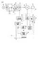
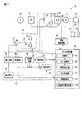
図1は、第1の実施形態におけるハイブリッド駆動型エレベータの制御装置の構成を示す図である。
このエレベータ10は、所定の駆動電力を受けて回転動作する電動機11と、この電動機11の回転軸に取り付けられて回転するシーブ12と、このシーブ12に巻き掛けられたロープ13の両端に吊り下げられた乗りかご14とカウンタウェイト(釣り合い重り)15などを備える。Hereinafter, embodiments will be described with reference to the drawings.
(First embodiment)
First, the first embodiment will be described.
FIG. 1 is a diagram illustrating a configuration of a control device for a hybrid drive elevator according to the first embodiment.
The
また、乗りかご14の駆動系として、商用電源16と、この商用電源16の交流電圧を直流電圧に変換する整流器17と、直流電圧のリプルを平滑化する平滑コンデンサ18と、直流電圧を可変電圧可変周波数の交流電圧に変換するインバータ19と、このインバータ19により供給される電動機11の電流を検出するインバータ電流検出装置20などを備える。 Further, as a driving system for the
なお、商用電源16は三相電源である。この三相電源による交流電圧が整流器17で全波整流され、平滑コンデンサ18にてリプル分が吸収されて直流に平滑化される。この平滑化された直流がインバータ19に与えられ、所定周波数の交流電圧に変換されて電動機11に駆動電力として供給される。 The
このような電力供給により、電動機11が回転駆動され、これに伴いシーブ12が回転し、そこに巻き掛けられたロープ13を介して乗りかご14とカウンタウェイト15が昇降路内をつるべ式に昇降動作する。 With such power supply, the
また、このエレベータ10は、乗りかご14の運転速度などを制御するための運転制御装置21を備える。
図2に運転制御装置21の構成を示す。この運転制御装置21は、速度指令部22と、速度検出部23と、速度制御部24と、荷重検出スイッチ部25と、荷重信号演算部26と、トルク指令判断部27と、インバータ電流制御部28などから構成される。The
FIG. 2 shows the configuration of the
速度指令部22は、図示せぬエレベータ制御盤から電動機11の運転指令を受けて、速度指令値を出力する。速度検出部23は、電動機11の現在の速度を検出する。速度制御部24は、速度指令値と速度検出値との偏差を求め、その偏差をなくすようなトルク指令を出力する。 The
荷重検出スイッチ部25は、乗りかご14の荷重を検出するためのスイッチであり、例えば荷重値に応じて選択的にオン動作する複数のスイッチからなる。荷重信号演算部26は、荷重検出スイッチ部25から出力される荷重信号に基づいてトルク補償値を演算する。 The load
具体的には、荷重検出スイッチ部25が3つのスイッチa、b、cから構成されるものとする。スイッチaは乗りかご14の荷重値が所定の積載重量(カウンタウェイト15と釣り合う重量)よりも重いときにONし、スイッチbは乗りかご14の荷重値が所定の積載重量のときにONし、スイッチcは乗りかご14の荷重値が前述の所定の積載重量よりも軽いときにONする。荷重信号演算部26は、これらのスイッチa、b、cのそれぞれのON信号に対し、例えば「−10」、「0」、「+10」なるトルク補償値を出力する。 Specifically, it is assumed that the load
トルク指令判断部27は、速度制御部24から出力されたトルク指令値と荷重信号演算部26から出力されたトルク補償値とを加算して得られる最終的なトルク指令値が許容範囲内にあるか否かを判断する。その結果、トルク指令値が許容範囲外であれば、許容範囲内に収めるようにリミッタをかける。 The torque
インバータ電流制御部28は、インバータ電流検出装置20によって検出された電流値とトルク指令判断部27から出力されるトルク指令値とに基づいて、電動機11に流す電流をトルク指令値に合わせて制御する。 Based on the current value detected by the inverter
このエレベータ10は、前述した構成に加え、ハイブリッド駆動系として、さらに蓄電装置30、充放電回路31、蓄電制御装置32を備える。
蓄電装置30は、ハイブリッド駆動型エレベータにおける電力供給手段であり、例えばニッケル水素電池や、リチウムイオン電池、リチウムポリマー電池などの2次電池や、電気2重層コンデンサといった大容量キャパシタなどからなり、回生運転時に電力供給ラインに生じる回生エネルギー(電力)を蓄えておき、次の力行運転時に前述のように蓄えた回生エネルギー(電力)を電力供給ラインに放電することで省電力化を図るものである。In addition to the configuration described above, the
The
充放電回路31は、蓄電装置30に対する充放電を切り替えるための回路である。この充放電回路31は、インバータ19への電力供給ラインである直流母線間に並列に接続される充電用スイッチング素子33および放電用スイッチング素子34、これらのスイッチング素子33,34の共通接続部に接続され、直流電力を平滑化する機能を有する直流リアクトル35などから構成される。 The charge /
蓄電制御装置32は、直流母線間電圧つまり平滑コンデンサ18の電圧を監視し、その電圧値に基づいて乗りかご14の運転状態が回生運転または力行運転であるかを判断し、その運転状態に応じて充放電回路31を制御して蓄電装置30に対する充放電を行うものである。 The power
具体的には、この蓄電制御装置32は、直流母線間電圧(平滑コンデンサ18の電圧)を検出する電圧検出部41と、充放電回路31を駆動して蓄電装置30に対する充放電を制御する充放電制御部42と、蓄電装置30の電圧を検出する電圧検出部43と、この電圧検出部43によって検出された蓄電装置30の電圧変化を監視する電圧変化監視部44と、電圧指令を出す電圧指令部45と、蓄電装置30に流れ込む電流を検出する電流検出部46などから構成される。 Specifically, the power
商用電源16から供給された三相交流電圧は整流器17にて直流電圧に変換された後、インバータ19にて所望の交流電圧に変換されて電動機11に供給される。その際に、乗りかご14が回生運転になると、インバータ19から入力端子側に回生エネルギーが戻されるので、直流母線間電圧は上昇することになる。 The three-phase AC voltage supplied from the
通常のエレベータでは、直流母線間電圧が一定値以上になったときに、インバータ19の入力端子側に設けられたスイッチング素子51を制御して回生抵抗52にてエネルギーを熱消費していた。これに対し、ハイブリッド駆動式エレベータでは、この回生エネルギーを有効利用するために蓄電装置30を備える。 In a normal elevator, when the DC bus voltage becomes equal to or higher than a certain value, the switching
ここで、蓄電装置30を備えたハイブリッド駆動式エレベータにおける回生エネルギーの充電と放電の動作について簡単に説明しておく。 Here, the operation of charging and discharging the regenerative energy in the hybrid drive elevator including the
(a)回生エネルギーの充電動作
上述したように、乗りかご14の回生運転時には、インバータ19から入力端子側に回生エネルギーが戻されるので、平滑コンデンサ18に回生エネルギーが蓄積され、インバータ19への電力供給ラインである直流母線間の電圧は徐々に上昇する。このときの電圧上昇は蓄電制御装置32内の電圧検出部41にて検出される。(A) Regenerative energy charging operation As described above, during the regenerative operation of the
ここで、蓄電制御装置32では、直流母線間の電圧が予め設定された基準値以上となると、電圧指令部45により蓄電装置30への充電に適した電圧となるまで降圧してから、充放電回路31内の充電用スイッチング素子33をONして蓄電装置30に充電を行う。 Here, in the power
このときの蓄電装置30の電圧変化は電圧検出部43を通じて電圧変化監視部44にて監視され、電圧指令部45に与えられる。この際、蓄電装置30に流れ込む電流を電流検出部46にて検出し、充放電制御部42にて充電電流を制御する。これにより、回生エネルギーを蓄電装置30に蓄えることが可能となる。 The voltage change of the
(b)回生エネルギーの放電動作
乗りかご14の力行運転時には、平滑コンデンサ18で平滑化された直流がインバータ19に供給されるので、インバータ19への電力供給ラインである直流母線間電圧は停止時よりも降下する。このときの電圧降下は蓄電制御装置32内の電圧検出部41にて検出される。(B) Regenerative energy discharge operation During the power running operation of the
蓄電制御装置32では、直流母線間電圧が予め設定された基準値よりも下がると、電圧指令部45にて設定された目標値まで蓄電装置30の電圧を昇圧して直流母線間電圧に突き合わせることで、充放電回路31内の放電用スイッチング素子34をONして蓄電装置30に蓄積された回生エネルギーを電力供給ラインへ放電する。この際、蓄電装置30から流れ出す電流を電流検出部46にて検出し、充放電制御部42にて放電電流を制御する。 In the power
本実施形態におけるエレベータは、SOC制御装置60を備える。このSOC制御装置60は、現在時刻を計時する計時部61、SOC設定部62、充放電指令部63を備える。
SOC設定部62は、エレベータ設置建屋側の使用電力ピーク時となる所定の時間帯において、エレベータの力行運転のためのパワーアシスト量、つまり蓄電装置30からの放電量が最大となるように、蓄電装置30のSOC範囲を拡大し、かつ上述の所定の時間帯以外では、蓄電装置30のSOC範囲を元に戻す。The elevator in the present embodiment includes an
The
充放電指令部63は、回生運転もしくは力行運転が開始されると、電圧検出部43による蓄電装置30の電圧検出値を取得し、この取得した電圧検出値が拡大後のSOC範囲内に対応する電圧値となるように蓄電制御装置32の充放電制御部42に指令を行なう。これにより、必要時における高出力制御を可能とし、かつ、蓄電装置30の高寿命化を実現する。 When the regenerative operation or the power running operation is started, the charge /
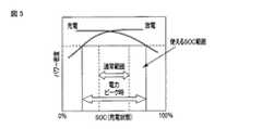
図3は、第1の実施形態におけるハイブリッド駆動型エレベータの制御装置に用いる蓄電装置のSOC範囲の可変の一例を示す図である。
本実施形態では、使用可能なSOC範囲、つまり一定以上のパワー密度による電力を出力できるSOC範囲を通常範囲と電力ピーク時範囲の2種類の間で切り替えることができる。FIG. 3 is a diagram illustrating an example of a variable SOC range of the power storage device used in the control device for the hybrid drive elevator according to the first embodiment.
In the present embodiment, the usable SOC range, that is, the SOC range in which power with a power density of a certain level or more can be output can be switched between the normal range and the power peak range.
通常のSOC範囲と電力ピーク時のSOC範囲とを比較すると、電力ピーク時のSOC範囲の下限値は、通常のSOC範囲の下限値より低く、電力ピーク時のSOC範囲の上限値は、通常のSOC範囲の上限値より高い。よって、SOC範囲を電力ピーク時の範囲としている場合には、充電量、放電量ともにSOC範囲を通常範囲としている場合と比較して多くすることが出来るので、高出力による運転制御が可能である。 Comparing the normal SOC range and the SOC range at the power peak, the lower limit value of the SOC range at the power peak is lower than the lower limit value of the normal SOC range, and the upper limit value of the SOC range at the power peak is It is higher than the upper limit of the SOC range. Therefore, when the SOC range is the range at the time of power peak, both the charge amount and the discharge amount can be increased compared to the case where the SOC range is the normal range, so that operation control with high output is possible. .
ただし、SOC範囲を電力ピーク時の範囲に切り替えている状態であると、SOC範囲を通常範囲に切り替えている状態と比較して蓄電装置30の寿命が減少するので、電力ピーク時以外では、SOC範囲を通常範囲に切り替える。これにより、必要時の高出力の運転制御と蓄電装置の長寿命化をともに実現することができる。 However, in the state where the SOC range is switched to the power peak range, the life of the
次に、図1に示した構成のハイブリッド駆動型エレベータの動作について説明する。
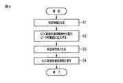
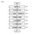
図4は、第1の実施形態におけるハイブリッド駆動型エレベータに備えられたSOC制御装置によって実行される運転制御処理の流れを示すフローチャートである。
初期状態では、現在時刻がエレベータ設置建屋内の電力ピーク時でなく、蓄電装置30のSOC範囲は通常範囲に設定されているものとする。
そして、現在時刻が建屋内の電力ピーク時である所定時間帯となったことをSOC制御装置60の計時部61が計時すると(ステップS1)、SOC設定部62は、蓄電装置30のSOC範囲を通常範囲から電力ピーク時範囲に拡大する(ステップS2)。Next, the operation of the hybrid drive elevator having the configuration shown in FIG. 1 will be described.
FIG. 4 is a flowchart showing a flow of operation control processing executed by the SOC control device provided in the hybrid drive elevator according to the first embodiment.
In the initial state, it is assumed that the current time is not the power peak time in the elevator installation building, and the SOC range of the
Then, when the
SOC制御装置60の充放電指令部63は、回生運転により蓄電装置30への充電が開始されると、蓄電制御装置32の電圧検出部43による蓄電装置30の電圧検出値を取得し、この取得した電圧検出値が拡大後のSOC範囲の上限値を超えないように蓄電制御装置32の充放電制御部42に指令を行なう。充放電制御部42は、指令を受けると、蓄電装置30のSOCが拡大後のSOC範囲の上限値を超えないように、電流検出部46による蓄電装置30に流れ込む電流の検出値を取得して充電電流を制御する。 When charging of the
また、充放電指令部63は、力行運転により蓄電装置30からの放電が開始されると、電圧検出部43による蓄電装置30の電圧検出値を取得し、この取得した電圧検出値が拡大後のSOC範囲の下限値未満とならないように蓄電制御装置32の充放電制御部42に指令を行なう。充放電制御部42は、指令を受けると、SOCが拡大後のSOC範囲の下限値未満とならないように、電流検出部46による蓄電装置30から流れ出す電流の検出値を取得して放電電流を制御する。 Moreover, when the discharge from the
そして、現在時刻が建屋内の電力ピーク時である所定時間帯でなくなったことをSOC制御装置60の計時部61が計時すると(ステップS3)、SOC設定部62は、蓄電装置30のSOC範囲を拡大前の通常範囲に戻す(ステップS4)。 Then, when the
SOC範囲拡大時における回生運転に伴う蓄電装置30への充電により当該蓄電装置30の電圧検出値が通常のSOC範囲の上限値を超えている際にSOC範囲を元に戻した場合、充放電指令部63は、力行運転に伴う放電によりSOCが通常範囲の上限値以下となった後は、再び回生運転がなされても、この上限値を超えて充電されないように充放電制御部42に指令を行なう。 When the SOC range is restored when the voltage detection value of the
また、SOC範囲拡大時における力行運転に伴う蓄電装置30からの放電により、当該蓄電装置30の電圧検出値が通常のSOC範囲の下限値未満となっている際にSOC範囲を元に戻した際、充放電指令部63は、力行運転に伴う放電によりSOCが通常範囲の下限値以上となった後は、再び力行運転がなされても、この下限値未満で放電されないように充放電制御部42に指令を行なう。 Further, when the SOC range is restored when the voltage detection value of the
以上のように、第1の実施形態におけるハイブリッド駆動型エレベータでは、建屋側の使用電力ピーク時となる所定の時間帯において、エレベータの運転のためのパワーアシスト量、つまり蓄電装置30からの放電量が増加するように、蓄電装置30のSOC範囲を拡大し、かつ上述の所定の時間帯以外では、蓄電装置30のSOC範囲を元に戻す。よって、必要時における高出力制御を可能とし、かつ、蓄電装置30の高寿命化を実現することができる。また、電力ピーク時における蓄電装置30からの放電量を増加させることができるので、電力ピーク時における商用電源からの使用電力を減少させることができるので、電力使用のコストを削減することができる。 As described above, in the hybrid drive type elevator according to the first embodiment, the power assist amount for operating the elevator, that is, the discharge amount from the
(第2の実施形態)
次に、第2の実施形態について説明する。なお、以下の各実施形態におけるハイブリッド駆動型エレベータの構成のうち図1に示したものと同一部分の説明は省略する。
本実施形態は、建屋の電力ピーク時の連続した力行運転により蓄電装置30のSOCが所定値以下となった場合に、エレベータ設置建屋における使用電力のピークを上昇させず、かつ、次の力行運転における蓄電装置30の蓄電量の保全のために、運転モードを、エコ運転モードに切り替えることを特徴とする。このエコ運転モードは、乗りかご走行の際の平均速度、最高速度、加速度を通常運転モードと比較して制限した運転モードである。(Second Embodiment)
Next, a second embodiment will be described. In addition, description of the same part as what was shown in FIG. 1 among the structures of the hybrid drive type elevator in each following embodiment is abbreviate | omitted.
In the present embodiment, when the SOC of the
図5は、第2の実施形態におけるハイブリッド駆動型エレベータの制御装置の構成を示す図である。
本実施形態では、SOC制御装置60は、第1の実施形態で説明した計時部61、SOC設定部62、充放電指令部63に加え、SOC検出部71、行先階検出部72、荷重検出部73、使用電力判断部74、運転モード切替部75をさらに備える。FIG. 5 is a diagram illustrating a configuration of a control device for a hybrid drive elevator according to the second embodiment.
In the present embodiment, the
SOC検出部71は、蓄電制御装置32の電圧検出部43による検出結果と蓄電装置30の満充電容量を比較することで、蓄電装置30の現在のSOCを検出する。行先階検出部72は、乗りかご14の行先階を運転制御装置21から取得することで行先階を検出する。荷重検出部73は、乗りかご14の図示しない荷重検出器により検出した荷重値を得る。 The
使用電力判断部74は、建屋の電力ピーク時において蓄電装置30のSOCが、次回以降の力行運転に伴う蓄電装置30からの放電により、当該蓄電装置30のSOCが拡大後のSOC範囲の下限値未満となってしまう可能性のある所定値V1以下となった場合に、次の力行運転における行先階および荷重値の検出結果をもとに、この運転に必要な電力量である使用電力量を判断する。The power
運転モード切替部75は、この判断された使用電力量と検出済みのSOCとを比較して、この使用電力量による運転を行なった場合に、蓄電装置30からの放電によるパワーアシストにより蓄電装置30のSOCが拡大後のSOC範囲の下限値未満となってしまう場合、運転モードを使用電力量の少ないエコ運転モードに切り替えるための機能を有する。 The operation
図6は、第2の実施形態におけるハイブリッド駆動型エレベータに備えられたSOC制御装置によって実行される運転制御処理の流れを示すフローチャートである。
ここでは、現在時刻が、建屋内の電力ピーク時である所定時間帯であって、第1の実施形態と同様に、蓄電装置30のSOC範囲が通常範囲から電力ピーク時範囲に拡大されているとする。また、運転モードは通常運転モードであるとする。FIG. 6 is a flowchart showing a flow of operation control processing executed by the SOC control device provided in the hybrid drive elevator according to the second embodiment.
Here, the current time is a predetermined time zone that is the power peak time in the building, and the SOC range of the
この状態で、SOC制御装置60のSOC検出部71は、蓄電装置30のSOCを検出し、このSOCが拡大後の範囲内の所定値V1以下となった場合(ステップS11)、行先階検出部72は、乗りかご14の行先階を検出し(ステップS12)、荷重検出部73は、かご荷重検出器により検出した荷重値を得る(ステップS13)。In this state,
そして、使用電力判断部74は、行先階の検出結果が次の運転が力行運転である場合、行先階および荷重値の検出結果をもとに、次の力行運転に要する使用電力量を計算する(ステップS14)。 Then, when the destination floor detection result is a power running operation, the power
運転モード切替部75は、使用電力判断部74により計算された使用電力量と検出済みのSOCとを比較して、この使用電力量による運転を行なった場合に、蓄電装置30からの放電によるパワーアシストにより蓄電装置30のSOCが拡大後のSOC範囲の下限値未満となってしまう場合、運転モードをエコ運転モードに切り替えるための指令を運転制御装置21に出力する。運転制御装置21は、この指令を入力すると、運転モードを通常運転モードからエコ運転モードに切り替える(ステップS15)。これにより、乗りかご走行の際の平均速度、最高速度、加速度が通常運転モードと比較して制限されるので、力行運転時における蓄電装置30からの放電量が減少し、蓄電装置30の蓄電量を保全することができる。 The operation
そして、運転が開始されて(ステップS16)、SOC検出部71により検出した蓄電装置30の現在のSOCが前述した所定値V1を超えた場合(ステップS17)、運転モード切替部75は、力行運転時における蓄電装置30からの放電量を減少させる必要がなくなったとして、運転モードを通常運転モードに切り替えるための指令を運転制御装置21に出力する。運転制御装置21は、この指令を入力すると、運転モードを通常運転モードに切り替える(ステップS18)。これにより、乗りかご14の走行速度を通常の速度に戻すことができるので、乗りかご14の走行速度が不必要に制限されない。Then, the operation is started (step S16), and if the current SOC of
以上のように、第2の実施形態におけるハイブリッド駆動型エレベータでは、建屋の電力ピーク時の連続した力行運転により蓄電装置30のSOCが所定値以下となった場合で、運転モードを、走行速度を制限したエコ運転モードに切り替えるので、建屋における使用電力のピークを上昇させず、かつ、力行運転時における蓄電装置30からの放電量を減少させて蓄電装置30の蓄電量を保全することができる。 As described above, in the hybrid drive type elevator according to the second embodiment, when the SOC of the
(第3の実施形態)
次に、第3の実施形態について説明する。
本実施形態は、第2の実施形態を前提とするものであり、運転モードをエコ運転モードに切り替えた状態で、蓄電装置30のSOCが更に低下してV2(<V1)以下となった場合、蓄電装置30からの放電量を制限し、この制限した状態で力行運転が連続して蓄電装置30のSOCが更に低下して所定値V3(<V2)以下となった場合、乗りかごの積載量を制限することで、蓄電装置30の蓄電量を保全することを特徴とする。(Third embodiment)
Next, a third embodiment will be described.
The present embodiment is premised on the second embodiment, and the SOC of the
図7は、第3の実施形態におけるハイブリッド駆動型エレベータの制御装置の構成を示す図である。
本実施形態では、SOC制御装置60は、第1および第2の実施形態で説明した計時部61、SOC設定部62、充放電指令部63、SOC検出部71、行先階検出部72、荷重検出部73、使用電力判断部74、運転モード切替部75に加え、放電制限指令部76、積載制限指令部77をさらに備える。FIG. 7 is a diagram illustrating a configuration of a control device for a hybrid drive elevator according to the third embodiment.
In the present embodiment, the
放電制限指令部76は、SOC検出部71により検出した蓄電装置30の現在のSOCが範囲内の所定値V2(<V1)以下となった場合、蓄電装置30からの放電量が制限されるように、蓄電制御装置32の充放電制御部42に指令を行なう。When the current SOC of the
積載制限指令部77は、SOC検出部71により検出した蓄電装置30の現在のSOCが範囲内の所定値V3(<V2)以下となった場合、乗りかご14の積載量が制限されるように運転制御装置21に指令を行なう。When the current SOC of the
図8は、第3の実施形態におけるハイブリッド駆動型エレベータに備えられたSOC制御装置によって実行される運転制御処理の流れを示すフローチャートである。
ここでは、現在時刻が、建屋内の電力ピーク時である所定時間帯であって、第1の実施形態と同様に、蓄電装置30のSOC範囲が通常範囲から電力ピーク時範囲に拡大されているとする。また、運転モードは通常運転モードであるとする。FIG. 8 is a flowchart showing a flow of operation control processing executed by the SOC control device provided in the hybrid drive elevator according to the third embodiment.
Here, the current time is a predetermined time zone that is the power peak time in the building, and the SOC range of the
そして、この状態で、SOC制御装置60のSOC検出部71は、蓄電装置30のSOCを検出し、このSOCが拡大後の範囲内の所定値V1以下となった場合(ステップS21)、第2の実施形態で説明したように、行先階検出部72は、乗りかご14の行先階を検出し(ステップS12)、荷重検出部73は、かご荷重検出器により検出した荷重値を得る(ステップS13)。In this state, when the
そして、使用電力判断部74は、行先階の検出結果が次の運転が力行運転である場合、行先階および荷重値の検出結果をもとに、次の運転に要する使用電力量を計算する(ステップS14)。 Then, when the next operation is a powering operation, the power
そして、第2の実施形態と同様に、使用電力判断部74により計算した使用電力量に応じた、運転モードの通常運転モードからエコ運転モードへの切り替えがなされる(ステップS15)。 Then, similarly to the second embodiment, the operation mode is switched from the normal operation mode to the eco operation mode according to the power consumption calculated by the power consumption determination unit 74 (step S15).
そして、力行運転が開始して(ステップS16)、蓄電装置30のSOCが減少して、SOC検出部71により検出した蓄電装置30の現在のSOCが拡大後の範囲内の第2の所定値V2以下(<V1)となった場合(ステップS22)、放電制限指令部76は、蓄電装置30からの放電量が制限されるように、充放電制御部42に指令を行なう。すると、充放電制御部42は、力行運転時における蓄電装置30からの単位時間当たりの放電量を指令前より制限する(ステップS23)。Then, the power running is started (step S16), the SOC of the
この状態で、力行運転が連続してなされるなどして、蓄電装置30のSOCがさらに減少して、SOC検出部71により検出した蓄電装置30の現在のSOCが拡大後の範囲内の所定値V3以下(<V2)となった場合(ステップS24)、積載制限指令部77は、蓄電装置30の蓄電量の保全のために、乗りかご14の積載量が制限されるように運転制御装置21に指令を行なう。すると、運転制御装置21は、乗りかご内における乗客への降車を促すアナウンスおよび戸開維持の基準となる積載基準値を指令前より低くする(ステップS25)。これにより、指令前より低い基準値の積載量にて、降車を促すアナウンスを乗客に行なって戸開を維持することになるので、乗りかご14の荷重を指令前より制限することができる。よって、乗りかご14の運転にかかる負荷が減少し、蓄電装置30の蓄電量を保全することができる。In this state, the power running operation is continuously performed, for example, so that the SOC of the
そして、力行運転が終了した後、回生運転がなされることで蓄電装置30のSOCが回復して、SOC検出部71により検出した蓄電装置30の現在のSOCが範囲内の所定値V3を超えた場合(ステップS26)、積載制限指令部77は、乗りかご14の積載量の制限が解除されるように運転制御装置21に指令を行なう。すると、運転制御装置21は、乗りかご内における乗客への降車を促すアナウンスの基準となる積載基準値を指令前に戻す(ステップS27)。これにより、乗客の人員の不必要な制限を行なわないようにすることができる。Then, after the power running operation is completed, the SOC of the
そして、さらなる回生運転により蓄電装置30のSOCがさらに回復して、SOC検出部71により検出した蓄電装置30の現在のSOCが拡大後の範囲内の所定値V2を超えた場合(ステップS28)、放電制限指令部76は、蓄電装置30からの放電量の制限が解除されるように、充放電制御部42に指令を行なう。すると、充放電制御部42は、力行運転時における蓄電装置30からの単位時間当たりの放電量の制限を解除する(ステップS29)。これにより、蓄電装置30からの放電量が元に戻るので、商用電源からの電力による消費電力を低減することができる。Then, when the SOC of
そして、蓄電装置30のSOCがさらに回復して、SOC検出部71により検出した蓄電装置30の現在のSOCが拡大後の範囲内の所定値V1を超えた場合(ステップS30)、運転モード切替部75は、運転モードを通常運転モードに切り替えるための指示信号を運転制御装置21に出力して、運転モードを通常運転モードに切り替える(ステップS31)。When the SOC of
以上のように、第3の実施形態におけるハイブリッド駆動型エレベータでは、第2の実施形態で説明したように運転モードをエコ運転モードに切り替えた状態で、蓄電装置30のSOCが更に低下して所定値以下となった場合、蓄電装置30からの放電量を制限し、この制限した状態で力行運転が連続して蓄電装置30のSOCが更に低下して所定値以下となった場合、乗りかごの積載量を制限することで、蓄電装置30の蓄電量の保全の効果を向上させることができる。 As described above, in the hybrid drive type elevator according to the third embodiment, the SOC of the
(第4の実施形態)
次に、第4の実施形態について説明する。
本実施形態は、エレベータ設置建屋内のエレベータ以外の機器に供給される電力が所定値を超える場合に、電力ピーク時と同様に、蓄電装置30のSOC範囲を拡大し、かつ運転モードをエコ運転モードに切り替えることで蓄電装置30の蓄電量を保全することを特徴とする。(Fourth embodiment)
Next, a fourth embodiment will be described.
In the present embodiment, when the power supplied to the equipment other than the elevator in the elevator-installed building exceeds a predetermined value, the SOC range of the
図9は、第4の実施形態におけるハイブリッド駆動型エレベータの制御装置の構成を示す図である。
本実施形態ではSOC制御装置60は、第1の実施形態で説明した計時部61、SOC設定部62、充放電指令部63に加え、エレベータ設置建屋内のエレベータ以外の機器に供給される電力およびその変動を検出する電力検出部81、運転モード切替部82をさらに備える。
運転モード切替部82は、客先電力量が一定量を超える場合に、運転モードをエコ運転モードに切り替えるための機能を有する。FIG. 9 is a diagram illustrating a configuration of a control device for a hybrid drive elevator according to the fourth embodiment.
In the present embodiment, the
The operation
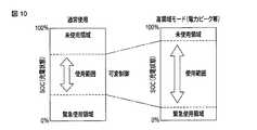
図10は、第4の実施形態におけるハイブリッド駆動型エレベータの制御装置に用いる蓄電装置のSOC範囲の可変の一例を示す図である。
図10に示すように、蓄電装置30は、未使用領域および緊急使用領域を有する。この未使用領域とは、SOCがSOC範囲の上限値となっても回生運転の際の充電に使用されない領域である。また、緊急未使用領域とは、当該未使用領域以外の蓄電領域のうちSOCがSOC範囲の下限値となっても力行運転の際の放電に使用されない領域である。FIG. 10 is a diagram illustrating an example of a variable SOC range of the power storage device used in the control device for the hybrid drive elevator according to the fourth embodiment.
As shown in FIG. 10,
本実施形態では、エレベータ設置建屋内のエレベータ以外の機器に供給される電力が所定値を超える場合に、蓄電装置30の使用モードを通常使用モードから高領域モードに変更することでSOCの範囲である使用範囲を拡大する。この拡大により、拡大前に充電に使用していなかった未使用領域の一部を充電に使用し、かつ、拡大前に放電に使用していなかった緊急使用領域の一部を放電に使用することで、回生運転の際の充電量および力行運転の際の放電量を使用範囲の拡大前より増加させることができる。 In the present embodiment, when the power supplied to equipment other than the elevator in the elevator-installed building exceeds a predetermined value, the usage mode of the
図11は、第4の実施形態におけるハイブリッド駆動型エレベータに備えられたSOC制御装置によって実行される運転制御処理の流れを示すフローチャートである。
本実施形態では、第1の実施形態で説明した動作とは別に、SOC制御装置60の電力検出部81は、エレベータ設置建屋内のエレベータ以外の機器に供給される電力である客先電力量を検出する(ステップS41)。これにより、エレベータの使用電力が増加しているか否かに関わらず、エレベータの設置建屋における全体の使用電力が増加しているか否かを検出することができる。FIG. 11 is a flowchart showing a flow of operation control processing executed by the SOC control device provided in the hybrid drive elevator according to the fourth embodiment.
In the present embodiment, separately from the operation described in the first embodiment, the
そして、電力検出部81により検出した客先電力量が一定量を超える場合(ステップS42)、運転モード切替部82は、エレベータの設置建屋における全体の使用電力を減少させることを目的として、運転モードをエコ運転モードに切り替えるための指示信号を運転制御装置21に出力して、運転モードを通常運転モードからエコ運転モードに切り替える(ステップS43)。 And when the customer electric energy detected by the electric
本実施形態では、運転モードを通常運転モードからエコ運転モードに切り替える際、蓄電装置30の使用モードを通常使用モードから図10に示した高領域モードに変更することでSOCの範囲である使用範囲を拡大する。これにより、回生運転の際の充電量および力行運転の際の放電量を使用範囲の拡大前より増加させることができ、エレベータにおける商用電源からの電力の使用電力量が減少するので、エレベータ設置建屋全体の使用電力を抑制することができる。エレベータ設置建屋全体の使用電力のコストを削減できる。 In the present embodiment, when the operation mode is switched from the normal operation mode to the eco operation mode, the use range that is the range of the SOC by changing the use mode of the
そして、エレベータ設置建屋内のエレベータ以外の機器に供給される電力が減少することにより、電力検出部81により検出した客先電力量が前述した一定量以下となった場合(ステップS44)、運転モード切替部82は、エレベータの設置建屋全体の使用電力を抑制する必要がなくなったとして、運転モード切替部82は、運転モードを通常運転モードに切り替えるための指示信号を運転制御装置21に出力して、運転モードを通常運転モードに切り替える(ステップS45)。 And when the customer electric energy detected by the electric
以上のように、第4の実施形態におけるハイブリッド駆動型エレベータでは、エレベータ設置建屋内のエレベータ以外の機器に供給される電力が所定値を超える場合に、蓄電装置30のSOC範囲を拡大し、かつ、運転モードをエコ運転モードに切り替えるので、エレベータにおける使用電力が減少し、その結果、エレベータの設置建屋における全体の使用電力を抑制することができる。 As described above, in the hybrid drive type elevator in the fourth embodiment, when the power supplied to devices other than the elevator in the elevator installation building exceeds a predetermined value, the SOC range of the
(第5の実施形態)
次に、第5の実施形態について説明する。
本実施形態は、建屋の電力ピーク時の連続した力行運転により蓄電装置30のSOCが所定値以下となった場合に、回生運転時の乗りかご14の乗りかご走行の際の平均速度、最高速度、加速度を増加させて、多くの回生エネルギーを蓄電装置30に充電することで、蓄電装置30の蓄電量を増加させることを特徴とする。(Fifth embodiment)
Next, a fifth embodiment will be described.
In the present embodiment, when the SOC of the
図12は、第5の実施形態におけるハイブリッド駆動型エレベータの制御装置の構成を示す図である。
本実施形態ではSOC制御装置60は、第1および第2の実施形態で説明した計時部61、SOC設定部62、充放電指令部63、SOC検出部71、行先階検出部72、荷重検出部73、使用電力判断部74に加え、建屋の電力ピーク時の連続した力行運転により蓄電装置30のSOCが所定値以下となった場合に、回生運転時の乗りかご14の走行速度の平均速度、最高速度、加速度を増加させるための速度可変指令部91をさらに備える。FIG. 12 is a diagram illustrating a configuration of a control device for a hybrid drive elevator according to the fifth embodiment.
In the present embodiment, the
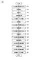
図13は、第5の実施形態におけるハイブリッド駆動型エレベータに備えられたSOC制御装置によって実行される運転制御処理の流れを示すフローチャートである。本実施形態での特徴的な動作は、充電促進運転を行なう以下のステップS51からS57の動作である。 FIG. 13 is a flowchart showing a flow of operation control processing executed by the SOC control device provided in the hybrid drive elevator according to the fifth embodiment. Characteristic operations in the present embodiment are the following operations in steps S51 to S57 for performing the charge promotion operation.
この状態で、SOC制御装置60のSOC検出部71は、蓄電装置30のSOCを検出し、このSOCが拡大後の範囲内の所定値以下となった場合(ステップS11)、行先階検出部72は、乗りかご14の行先階を検出し(ステップS12)、荷重検出部73は、図示しないかご荷重検出器により検出した荷重値を検出する(ステップS13)。 In this state, the
そして、使用電力判断部74は、行先階の検出結果が次の運転が回生運転である事を示す場合、行先階および荷重値の検出結果をもとに、次の運転に要する使用電力量を計算する。 Then, when the detection result of the destination floor indicates that the next operation is a regenerative operation, the power
そして、使用電力判断部74により計算した使用電力量が少なく、回生運転により回生電力が蓄電装置30に充電できる電力量であれば、運転制御装置21は、回生運転時の運転モードを通常運転モードから充電促進運転、つまり、回生運転により蓄電装置30に充電する充電量を通常より多くする運転に切り替える(ステップS51)。 If the power consumption calculated by the power
そして、回生運転が開始されると(ステップS52)、速度可変指令部91は、乗りかご14の走行速度の平均速度、最高速度、加速度を増加させるための指令を運転制御装置21に出力する。運転制御装置21は、この指令を入力すると、現在の回生運転における乗りかご14の走行速度の平均速度、最高速度、加速度を増加させる(ステップS53)。これにより、電動機11の回転数が多くなるので、多くの回生エネルギーを蓄電装置30に充電することが可能となる。 When the regenerative operation is started (step S52), the variable speed command unit 91 outputs a command for increasing the average speed, the maximum speed, and the acceleration of the traveling speed of the
そして、回生運転が終了すると(ステップS54)、速度可変指令部91は、乗りかご14の走行速度の平均速度、最高速度、加速度を元に戻すための指令を運転制御装置21に出力する。運転制御装置21は、この指令を入力すると、以後の運転による乗りかご14の走行速度の平均速度、最高速度、加速度を元に戻す(ステップS55)。 When the regenerative operation ends (step S54), the variable speed command unit 91 outputs a command for returning the average speed, the maximum speed, and the acceleration of the traveling speed of the
この状態で、SOC制御装置60のSOC検出部71は、蓄電装置30のSOCを検出し、このSOCが拡大後の範囲内の所定値V1を超えた場合(ステップS56)、運転制御装置21は、運転モードを充電促進運転から通常運転モードに切り替える(ステップS57)
以上のように、第5の実施形態では、建屋の電力ピーク時の連続した力行運転により蓄電装置30のSOCが所定値以下となった場合に、回生運転時の乗りかご14の走行速度の平均速度、最高速度、加速度を増加させて、多くの回生エネルギーを蓄電装置30に充電するので、蓄電装置30の蓄電量を増加させることができる。In this state,
As described above, in the fifth embodiment, when the SOC of the
(第6の実施形態)
次に、第6の実施形態について説明する。
本実施形態は、エレベータ設置建屋におけるエレベータ以外の機器の使用電力量の変動幅が所定の範囲内となるように、運転開始前に当該運転にかかる使用電力量を計算し、この計算した使用電力量をもとに、蓄電装置30のSOC、エレベータの使用電力および回生電力をもとに、蓄電装置30による充放電量を可変制御することを特徴とする。(Sixth embodiment)
Next, a sixth embodiment will be described.
In the present embodiment, the amount of power used for the operation is calculated before the start of operation so that the fluctuation range of the amount of power used by devices other than the elevator in the elevator installation building is within a predetermined range. Based on the amount, the charge / discharge amount by the
図14は、第6の実施形態におけるハイブリッド駆動型エレベータの制御装置の構成を示す図である。
本実施形態は、SOC制御装置60は、第1および第2の実施形態で説明した計時部61、SOC設定部62、充放電指令部63、SOC検出部71、行先階検出部72、荷重検出部73、使用電力判断部74に加え、必要に応じて蓄電装置30による充放電量を可変制御するSOC可変制御部101をさらに備える。FIG. 14 is a diagram illustrating a configuration of a control device for a hybrid drive elevator according to the sixth embodiment.
In the present embodiment, the
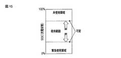
図15は、第6の実施形態におけるハイブリッド駆動型エレベータの制御装置に用いる蓄電装置のSOC範囲の可変の一例を示す図である。
図15に示すように、蓄電装置30は、未使用領域および緊急使用領域を有する。本実施形態では、エレベータ設置建屋におけるエレベータ以外の機器の使用電力量の変動幅が所定の範囲内となるように、SOCの範囲である使用範囲を可変する。この可変により、回生運転の際の充電量および力行運転の際の放電量を可変することができるので、エレベータ設置建屋におけるエレベータ以外の機器の使用電力量の変動幅を所定の範囲内にすることができる。FIG. 15 is a diagram illustrating an example of variable SOC range of the power storage device used in the control device for the hybrid drive elevator according to the sixth embodiment.
As shown in FIG. 15, the
図16は、第6の実施形態におけるハイブリッド駆動型エレベータに備えられたSOC制御装置によって実行される運転制御処理の流れを示すフローチャートである。
まず、行先階検出部72は、乗りかご14の行先階を検出し(ステップS12)、荷重検出部73は、図示しないかご荷重検出器により検出した荷重値を検出する(ステップS13)。FIG. 16 is a flowchart showing a flow of operation control processing executed by the SOC control device provided in the hybrid drive elevator according to the sixth embodiment.
First, the
そして、使用電力判断部74は、行先階の検出結果が次の運転が力行運転である場合、行先階および荷重値の検出結果をもとに、蓄電装置30のSOCの範囲を可変しない場合における、次の運転開始から終了までの使用電力量の時間特性を計算する(ステップS14)。 In the case where the detection result of the destination floor is the next driving operation, the power
SOC検出部71は蓄電装置30のSOCを検出する(ステップS61)。そして、SOC可変制御部101は、商用電源の使用電力量の変動幅が所定範囲内となるように蓄電装置30のSOCの範囲を可変する(ステップS62)。 The
具体的には、使用電力判断部74による計算結果をもとに、運転開始から終了までに使用電力量が変動幅の基準値、ここでは平均使用電力量に対して上昇または下降する場合、この上昇幅もしくは下降幅に応じて、蓄電装置30のSOCの範囲を拡大して、力行運転時により多くの電力が放電されるようにし、また、回生運転時により多くの電力が充電されるようにすることで、運転開始から終了までの商用電源の使用電力量の変動幅を抑制する。
そして、この運転が終了すると(ステップS63)、SOC可変制御部101は、蓄電装置30のSOCの範囲を元に戻す(ステップS64)。Specifically, based on the calculation result by the power
When this operation ends (step S63), SOC
以上説明したように、第6の実施形態では、運転開始から終了までに使用電力量が変動幅の基準値に対して上昇または下降する場合に、蓄電装置30のSOCを可変制御して、充放電量を多くすることで、運転開始から終了までの商用電源の使用電力量の変動幅を抑制するので、エレベータ設置建屋におけるエレベータ以外の機器の使用電力量の変動幅を所定の範囲内とすることができる。 As described above, in the sixth embodiment, when the amount of power used rises or falls with respect to the reference value of the fluctuation range from the start to the end of operation, the SOC of the
(第7の実施形態)
次に、第7の実施形態について説明する。
本実施形態は、蓄電装置30のSOCが所定値以下であって、かつ現在時刻が夜間などの、エレベータ設置建屋全体の使用電力量が少ない所定時間帯にある場合に、商用電源からの電力を蓄電装置30へ充電することを特徴とする。(Seventh embodiment)
Next, a seventh embodiment will be described.
In the present embodiment, when the SOC of the
図17は、第7の実施形態におけるハイブリッド駆動型エレベータの制御装置の構成を示す図である。
本実施形態ではSOC制御装置60は、第1および第2の実施形態で説明した計時部61、SOC設定部62、充放電指令部63、SOC検出部71に加え、エレベータ設置建屋全体の使用電力量が少ない所定時間帯にある場合に、商用電源からの電力を蓄電装置30へ充電するための充電指令部111および、商用電源からの電力を蓄電装置30へ充電する際の充電効率を向上させるためにインバータ19のキャリア周波数を上昇させる周波数可変指令部112を備える。FIG. 17 is a diagram illustrating a configuration of a control device for a hybrid drive elevator according to the seventh embodiment.
In the present embodiment, the
図18は、第7の実施形態におけるハイブリッド駆動型エレベータに備えられたSOC制御装置によって実行される運転制御処理の流れを示すフローチャートである。
まず、現在時刻が、エレベータ設置建屋全体の使用電力量が少ない夜間時間帯となったことをSOC制御装置60の計時部61が計時している際に(ステップS71)、SOC制御装置60のSOC検出部71は、蓄電装置30のSOCを検出し、このSOCが所定値以下となった場合(ステップS72)、周波数可変指令部112は、インバータ19のキャリア周波数を上昇させる指令を運転制御装置21に出力し、運転制御装置21は、この指令を入力すると、インバータ19のキャリア周波数を上昇させる(ステップS73)。そして、充電指令部111は、商用電源から蓄電装置30への充電指令を蓄電制御装置32に出力する。蓄電制御装置32は、この指令を入力すると商用電源から蓄電装置30への充電を制御する(ステップS74)。ここで、インバータ19のキャリア周波数が高い場合、充電効率が向上する。FIG. 18 is a flowchart showing a flow of an operation control process executed by the SOC control device provided in the hybrid drive elevator according to the seventh embodiment.
First, when the
ここで、蓄電制御装置32では、直流母線間の電圧が予め設定された基準値以上となると、電圧指令部45により蓄電装置30への充電に適した電圧となるまで降圧してから、充放電回路31内の充電用スイッチング素子33をONして蓄電装置30に充電を行う。 Here, in the power
このときの蓄電装置30の電圧変化は電圧検出部43を通じて電圧変化監視部44にて監視され、電圧指令部45に与えられる。この際、蓄電装置30に流れ込む電流を電流検出部46にて検出し、充放電制御部42にて充電電流を制御する。これにより、商用電源を蓄電装置30に蓄えることが可能となる。 The voltage change of the
そして、SOC検出部71により検出した蓄電装置30の現在のSOCが前述した所定値を超えた場合(ステップS75)、周波数可変指令部112は、インバータ19のキャリア周波数を元に戻す指令を運転制御装置21に出力し、運転制御装置21は、この指令を入力すると、インバータ19のキャリア周波数を元に戻す(ステップS76)。このようにインバータ19のキャリア周波数を元に戻すのは、キャリア周波数を上昇させた状態が継続すると、インバータ19のスイッチング素子の寿命が低下するからである。 When the current SOC of
そして、充電指令部111は、商用電源から蓄電装置30への充電終了指令を充放電制御部42に出力する。充放電制御部42は、この指令を入力すると商用電源から蓄電装置30への充電を終了する(ステップS77)。 Then,
以上説明したように、第7の実施形態では、商用電源からの電力を蓄電装置30へ充電する制御を行なうので、回生運転を行なっていない場合でも蓄電装置30への充電を行なうことができる。このような制御は、エレベータ設置建屋全体の使用電力量が少ない所定時間帯にある場合に行なうので、商用電源からの充電によりエレベータ以外の機器の使用に支障をきたすことはない。 As described above, in the seventh embodiment, since control from charging power from the commercial power source to the
これらの各実施形態によれば、必要時は蓄電装置による高出力を行なって、かつ当該蓄電装置の高寿命化を実現することが可能になるハイブリッド駆動型エレベータを提供することができる。
発明のいくつかの実施形態を説明したが、これらの実施形態は、例として提示したものであり、発明の範囲を限定することは意図していない。これら新規な実施形態は、その他の様々な形態で実施されることが可能であり、発明の要旨を逸脱しない範囲で、種々の省略、置き換え、変更を行うことができる。これら実施形態やその変形は、発明の範囲や要旨に含まれるとともに、特許請求の範囲に記載された発明とその均等の範囲に含まれる。According to each of these embodiments, it is possible to provide a hybrid drive type elevator that makes it possible to perform high output by the power storage device when necessary and to achieve a long life of the power storage device.
Although several embodiments of the invention have been described, these embodiments are presented by way of example and are not intended to limit the scope of the invention. These novel embodiments can be implemented in various other forms, and various omissions, replacements, and changes can be made without departing from the scope of the invention. These embodiments and modifications thereof are included in the scope and gist of the invention, and are included in the invention described in the claims and the equivalents thereof.
11…電動機、12…シーブ、13…ロープ、14…乗りかご、15…カウンタウェイト、16…商用電源、17…整流器、18…平滑コンデンサ、19…インバータ、20…インバータ電流検出装置、21…運転制御装置、22…速度指令部、23…速度検出部、24…速度制御部、25…荷重検出スイッチ部、26…荷重信号演算部、27…トルク指令判断部、28…インバータ電流制御部、30…蓄電装置、31…充放電回路、32…蓄電制御装置、33…充電用スイッチング素子、34…放電用スイッチング素子、35…直流リアクトル、41…電圧検出部、42…充放電制御部、43…電圧検出部、44…電圧変化監視部、45…電圧指令部、46…電流検出部、51…スイッチング素子、52…回生抵抗、60…SOC制御装置、61…計時部、62…SOC設定部、63…充放電指令部、71…SOC検出部、72…行先階検出部、73…荷重検出部、74…使用電力判断部、75,82…運転モード切替部、76…放電制限指令部、77…積載制限指令部、81…電力検出部、91…速度可変指令部、101…SOC可変制御部、111…充電指令部、112…周波数可変指令部。 DESCRIPTION OF
Claims (8)
Translated fromJapaneseこの蓄電手段の充放電を制御する蓄電制御手段と、
前記蓄電手段の充電状態を検出する蓄電状態検出手段と、
前記蓄電手段からの放電量の増加を要する所定の時間帯において、前記蓄電手段における前記満充電容量に対する現在の充電容量の比率の範囲を拡大させる充放電制御手段と、
を備え、
前記充放電制御手段は、
前記所定の時間帯でなくなった場合の、前記蓄電手段における前記満充電容量に対する現在の充電容量の比率の範囲を拡大前の範囲に戻すことを特徴とするハイブリッド駆動型エレベータの制御装置。Stores the power generated in the power supply line during regenerative operation of the elevator car so that the ratio of the current charge capacity to the full charge capacity is within a predetermined range, and the stored power during power runningis the lower limit within the predetermined range. Power storage means for supplying power to the power supply linewithin a range not less than a value ;
Power storage control means for controlling charging / discharging of the power storage means;
Power storage state detection means for detecting a charge state of the power storage means;
Charge / discharge control means for expanding the range of the ratio of the current charge capacity to the full charge capacity in the power storage means in a predetermined time zone that requires an increase in the amount of discharge from the power storagemeans ;
Equipped witha,
The charge / discharge control means includes
A control apparatus for a hybrid drive type elevator, wherein the range of the ratio of the current charge capacity to the full charge capacity in the power storage means when the predetermined time period is not reached is returned tothe range before expansion .
ことを特徴とする請求項1に記載のハイブリッド駆動型エレベータの制御装置。Driving to reduce the speed of the car when the ratio of the current charging capacity to the full charging capacity in the power storage means is not more than a predetermined value that requires maintenance of the current charging capacity in the predetermined time zone The hybrid drive elevator control device according to claim 1, further comprising control means.
ことを特徴とする請求項2に記載のハイブリッド駆動型エレベータの制御装置。After the ratio of the current charge capacity to the full charge capacity in the power storage means is less than or equal to the predetermined value that requires maintenance of the current charge capacity, the ratio is less than the predetermined value from the power storage means. The hybrid drive type elevator according to claim2 , further comprising: a discharge limiting unit that limits a discharge amount from the power storage means when the discharge voltage becomes equal to or less than a predetermined second value that requires a discharge limit. Control device.
ことを特徴とする請求項3に記載のハイブリッド駆動型エレベータの制御装置。When the ratio is equal to or less than the predetermined second value, and the ratio is smaller than the predetermined second value and is equal to or less than a third value that requires the loading limit of the car, The hybrid drive elevator control device according to claim3 , further comprising a load limiting unit that limits a load limit value of the car.
前記充放電制御手段は、
前記検出した電力量がエレベータの設置建屋における全体の使用電力の減少を要する所定値以上となった場合に、前記蓄電手段における前記満充電容量に対する現在の充電容量の比率の範囲を拡大させる
ことを特徴とする請求項1に記載のハイブリッド駆動型エレベータの制御装置。It further comprises an electric energy detection means for detecting electric energy used other than the elevator in the elevator installation building,
The charge / discharge control means includes
Expanding the range of the ratio of the current charge capacity to the full charge capacity in the power storage means when the detected power amount is equal to or greater than a predetermined value that requires a reduction in the total power consumption in the elevator installation building. The hybrid drive elevator control device according to claim 1, wherein the control device is a hybrid drive elevator control device.
ことを特徴とする請求項1に記載のハイブリッド駆動型エレベータの制御装置。If the ratio of the current charge capacity for the full-charge capacity in the power storage means is equal to or less than a predetermined value, variable as during regenerative operation, power storage speed of the car to thelivestock conducting means is promoted The hybrid drive elevator control device according to claim 1, further comprising operation control means for performing the operation control.
ことを特徴とする請求項1に記載のハイブリッド駆動型エレベータの制御装置。Before starting the operation of the car, calculate the amount of power used from the start of the operation to the end of the operation so that the fluctuation amount of the power used by the elevator and other than the elevator in the elevator installation building is within the specified range. 2. The control apparatus for a hybrid drive type elevator according to claim 1, wherein the charge / discharge amount of the power storage unit is variably controlled so that the fluctuation amount of the electric power is within a predetermined range.
ことを特徴とする請求項1に記載のハイブリッド駆動型エレベータの制御装置。When the ratio is equal to or less than a predetermined value and the current time is a predetermined time zone suitable for charging the power storagemeans , the power storage from a commercial power source that supplies power to various devices including the elevator in the elevator installation building2. The control apparatus for a hybrid drive type elevator according to claim 1, wherein the chargingmeans is charged.
Priority Applications (2)
| Application Number | Priority Date | Filing Date | Title |
|---|---|---|---|
| JP2011158411AJP5839873B2 (en) | 2011-07-19 | 2011-07-19 | Control device for hybrid drive elevator |
| CN2012102495743ACN102887402A (en) | 2011-07-19 | 2012-07-18 | Device for controlling hybrid drive elevator |
Applications Claiming Priority (1)
| Application Number | Priority Date | Filing Date | Title |
|---|---|---|---|
| JP2011158411AJP5839873B2 (en) | 2011-07-19 | 2011-07-19 | Control device for hybrid drive elevator |
Publications (2)
| Publication Number | Publication Date |
|---|---|
| JP2013023319A JP2013023319A (en) | 2013-02-04 |
| JP5839873B2true JP5839873B2 (en) | 2016-01-06 |
Family
ID=47531112
Family Applications (1)
| Application Number | Title | Priority Date | Filing Date |
|---|---|---|---|
| JP2011158411AActiveJP5839873B2 (en) | 2011-07-19 | 2011-07-19 | Control device for hybrid drive elevator |
Country Status (2)
| Country | Link |
|---|---|
| JP (1) | JP5839873B2 (en) |
| CN (1) | CN102887402A (en) |
Cited By (1)
| Publication number | Priority date | Publication date | Assignee | Title |
|---|---|---|---|---|
| US20230010424A1 (en)* | 2019-12-18 | 2023-01-12 | Honda Motor Co., Ltd. | Electric power device, display device, charging rate calculation method, and memory medium |
Families Citing this family (3)
| Publication number | Priority date | Publication date | Assignee | Title |
|---|---|---|---|---|
| CN104578848B (en)* | 2015-01-28 | 2018-03-30 | 哈尔滨工业大学 | A kind of ultrahigh speed generator rectifier based on the matching of automatic energy consumption |
| CN109455605B (en)* | 2017-09-06 | 2020-05-01 | 上海三菱电梯有限公司 | Elevator energy-saving device |
| CN109802606B (en)* | 2019-01-16 | 2020-09-25 | 西北工业大学 | Bus capacitor energy discharge method of electric automobile driving system |
Family Cites Families (12)
| Publication number | Priority date | Publication date | Assignee | Title |
|---|---|---|---|---|
| JPS56155166A (en)* | 1980-04-30 | 1981-12-01 | Mitsubishi Electric Corp | Controller for power consumption of elevator |
| JPS59149284A (en)* | 1983-02-16 | 1984-08-27 | 三菱電機株式会社 | elevator control device |
| JPS6225833A (en)* | 1985-07-25 | 1987-02-03 | 株式会社東芝 | Elevator controller |
| CA2391616C (en)* | 1999-11-17 | 2007-04-03 | Fujitec Co., Ltd. | Power source device for a.c. elevator |
| JP4409692B2 (en)* | 1999-12-28 | 2010-02-03 | 三菱電機株式会社 | Elevator control device |
| JP2001240323A (en)* | 2000-02-28 | 2001-09-04 | Mitsubishi Electric Corp | Elevator control device |
| JP2002145543A (en)* | 2000-11-09 | 2002-05-22 | Mitsubishi Electric Corp | Elevator control device |
| JP3917573B2 (en)* | 2003-09-10 | 2007-05-23 | 株式会社日立製作所 | Power storage system |
| JP2006044887A (en)* | 2004-08-05 | 2006-02-16 | Toshiba Elevator Co Ltd | Elevator control system |
| JP4864440B2 (en)* | 2005-12-07 | 2012-02-01 | 三菱電機株式会社 | Elevator equipment |
| JP5173276B2 (en)* | 2007-06-22 | 2013-04-03 | パナソニック株式会社 | Power supply system, power supply control method for power supply system, and power supply control program therefor |
| BRPI0823032A2 (en)* | 2008-08-15 | 2015-07-28 | Otis Elevator Co | Method and system for managing power in an elevator system |
- 2011
- 2011-07-19JPJP2011158411Apatent/JP5839873B2/enactiveActive
- 2012
- 2012-07-18CNCN2012102495743Apatent/CN102887402A/enactivePending
Cited By (2)
| Publication number | Priority date | Publication date | Assignee | Title |
|---|---|---|---|---|
| US20230010424A1 (en)* | 2019-12-18 | 2023-01-12 | Honda Motor Co., Ltd. | Electric power device, display device, charging rate calculation method, and memory medium |
| US12358398B2 (en)* | 2019-12-18 | 2025-07-15 | Honda Motor Co., Ltd. | Electric power device, display device, charging rate calculation method, and memory medium |
Also Published As
| Publication number | Publication date |
|---|---|
| CN102887402A (en) | 2013-01-23 |
| JP2013023319A (en) | 2013-02-04 |
Similar Documents
| Publication | Publication Date | Title |
|---|---|---|
| JP5240685B2 (en) | elevator | |
| CN101434359B (en) | Power supply system of elevator | |
| JP5805297B2 (en) | Elevator equipment | |
| JP5839873B2 (en) | Control device for hybrid drive elevator | |
| JP5741686B2 (en) | Elevator control device | |
| JP4812262B2 (en) | Elevator control device | |
| JP5770112B2 (en) | Control device for hybrid drive elevator | |
| JP2005089096A (en) | Elevator control device | |
| JP5386457B2 (en) | Power regeneration device | |
| JP4864440B2 (en) | Elevator equipment | |
| JP4402409B2 (en) | Elevator control device | |
| JP2003333891A (en) | MOTOR DRIVE DEVICE, POWER SUPPLY DEVICE USED FOR THE SAME, AND METHOD OF REDUCING POWER SUPPLY CAPACITY OF MOTOR DRIVE DEVICE | |
| JP2010180003A (en) | Elevator power supply apparatus | |
| JP5772118B2 (en) | Lifting device drive system and non-powered lifting device including the same | |
| JP2005324886A (en) | Control device of hybrid drive type elevator | |
| EP2845831A1 (en) | Elevator control apparatus | |
| JP5173124B2 (en) | Elevator control device | |
| JP2014009041A (en) | Elevator control device | |
| JP2005324887A (en) | Control device of hybrid drive type elevator | |
| JP2005324888A (en) | Control device of hybrid drive type elevator | |
| JP5855256B2 (en) | Elevator regenerative power storage control device | |
| JP2005324880A (en) | Elevator control device | |
| JP2005324883A (en) | Elevator control device | |
| JP2005324882A (en) | Elevator control device | |
| JP2007084188A (en) | Elevator control device |
Legal Events
| Date | Code | Title | Description |
|---|---|---|---|
| RD02 | Notification of acceptance of power of attorney | Free format text:JAPANESE INTERMEDIATE CODE: A7422 Effective date:20130828 | |
| A621 | Written request for application examination | Free format text:JAPANESE INTERMEDIATE CODE: A621 Effective date:20140320 | |
| A977 | Report on retrieval | Free format text:JAPANESE INTERMEDIATE CODE: A971007 Effective date:20150206 | |
| A131 | Notification of reasons for refusal | Free format text:JAPANESE INTERMEDIATE CODE: A131 Effective date:20150224 | |
| A521 | Written amendment | Free format text:JAPANESE INTERMEDIATE CODE: A523 Effective date:20150427 | |
| TRDD | Decision of grant or rejection written | ||
| A01 | Written decision to grant a patent or to grant a registration (utility model) | Free format text:JAPANESE INTERMEDIATE CODE: A01 Effective date:20151013 | |
| A61 | First payment of annual fees (during grant procedure) | Free format text:JAPANESE INTERMEDIATE CODE: A61 Effective date:20151110 | |
| R150 | Certificate of patent or registration of utility model | Ref document number:5839873 Country of ref document:JP Free format text:JAPANESE INTERMEDIATE CODE: R150 |