JP5837060B2 - Injection molding process and products manufactured using it - Google Patents
Injection molding process and products manufactured using itDownload PDFInfo
- Publication number
- JP5837060B2 JP5837060B2JP2013519852AJP2013519852AJP5837060B2JP 5837060 B2JP5837060 B2JP 5837060B2JP 2013519852 AJP2013519852 AJP 2013519852AJP 2013519852 AJP2013519852 AJP 2013519852AJP 5837060 B2JP5837060 B2JP 5837060B2
- Authority
- JP
- Japan
- Prior art keywords
- draft
- plunger
- layer
- syringe
- molding
- Prior art date
- Legal status (The legal status is an assumption and is not a legal conclusion. Google has not performed a legal analysis and makes no representation as to the accuracy of the status listed.)
- Expired - Fee Related
Links
Images


Classifications
- B—PERFORMING OPERATIONS; TRANSPORTING
- B29—WORKING OF PLASTICS; WORKING OF SUBSTANCES IN A PLASTIC STATE IN GENERAL
- B29C—SHAPING OR JOINING OF PLASTICS; SHAPING OF MATERIAL IN A PLASTIC STATE, NOT OTHERWISE PROVIDED FOR; AFTER-TREATMENT OF THE SHAPED PRODUCTS, e.g. REPAIRING
- B29C45/00—Injection moulding, i.e. forcing the required volume of moulding material through a nozzle into a closed mould; Apparatus therefor
- B29C45/17—Component parts, details or accessories; Auxiliary operations
- B29C45/72—Heating or cooling
- B29C45/73—Heating or cooling of the mould
- A—HUMAN NECESSITIES
- A61—MEDICAL OR VETERINARY SCIENCE; HYGIENE
- A61B—DIAGNOSIS; SURGERY; IDENTIFICATION
- A61B5/00—Measuring for diagnostic purposes; Identification of persons
- A61B5/14—Devices for taking samples of blood ; Measuring characteristics of blood in vivo, e.g. gas concentration within the blood, pH-value of blood
- A61B5/1405—Devices for taking blood samples
- A61B5/1438—Devices for taking blood samples using pre-evacuated means
- A—HUMAN NECESSITIES
- A61—MEDICAL OR VETERINARY SCIENCE; HYGIENE
- A61B—DIAGNOSIS; SURGERY; IDENTIFICATION
- A61B5/00—Measuring for diagnostic purposes; Identification of persons
- A61B5/15—Devices for taking samples of blood
- A61B5/150007—Details
- A61B5/150015—Source of blood
- A61B5/15003—Source of blood for venous or arterial blood
- A—HUMAN NECESSITIES
- A61—MEDICAL OR VETERINARY SCIENCE; HYGIENE
- A61B—DIAGNOSIS; SURGERY; IDENTIFICATION
- A61B5/00—Measuring for diagnostic purposes; Identification of persons
- A61B5/15—Devices for taking samples of blood
- A61B5/150007—Details
- A61B5/150206—Construction or design features not otherwise provided for; manufacturing or production; packages; sterilisation of piercing element, piercing device or sampling device
- A61B5/150236—Pistons, i.e. cylindrical bodies that sit inside the syringe barrel, typically with an air tight seal, and slide in the barrel to create a vacuum or to expel blood
- A—HUMAN NECESSITIES
- A61—MEDICAL OR VETERINARY SCIENCE; HYGIENE
- A61B—DIAGNOSIS; SURGERY; IDENTIFICATION
- A61B5/00—Measuring for diagnostic purposes; Identification of persons
- A61B5/15—Devices for taking samples of blood
- A61B5/150007—Details
- A61B5/150206—Construction or design features not otherwise provided for; manufacturing or production; packages; sterilisation of piercing element, piercing device or sampling device
- A61B5/150244—Rods for actuating or driving the piston, i.e. the cylindrical body that sits inside the syringe barrel, typically with an air tight seal, and slides in the barrel to create a vacuum or to expel blood
- A—HUMAN NECESSITIES
- A61—MEDICAL OR VETERINARY SCIENCE; HYGIENE
- A61B—DIAGNOSIS; SURGERY; IDENTIFICATION
- A61B5/00—Measuring for diagnostic purposes; Identification of persons
- A61B5/15—Devices for taking samples of blood
- A61B5/150007—Details
- A61B5/150206—Construction or design features not otherwise provided for; manufacturing or production; packages; sterilisation of piercing element, piercing device or sampling device
- A61B5/150259—Improved gripping, e.g. with high friction pattern or projections on the housing surface or an ergonometric shape
- A—HUMAN NECESSITIES
- A61—MEDICAL OR VETERINARY SCIENCE; HYGIENE
- A61B—DIAGNOSIS; SURGERY; IDENTIFICATION
- A61B5/00—Measuring for diagnostic purposes; Identification of persons
- A61B5/15—Devices for taking samples of blood
- A61B5/150007—Details
- A61B5/150206—Construction or design features not otherwise provided for; manufacturing or production; packages; sterilisation of piercing element, piercing device or sampling device
- A61B5/150274—Manufacture or production processes or steps for blood sampling devices
- A—HUMAN NECESSITIES
- A61—MEDICAL OR VETERINARY SCIENCE; HYGIENE
- A61B—DIAGNOSIS; SURGERY; IDENTIFICATION
- A61B5/00—Measuring for diagnostic purposes; Identification of persons
- A61B5/15—Devices for taking samples of blood
- A61B5/150007—Details
- A61B5/150351—Caps, stoppers or lids for sealing or closing a blood collection vessel or container, e.g. a test-tube or syringe barrel
- A—HUMAN NECESSITIES
- A61—MEDICAL OR VETERINARY SCIENCE; HYGIENE
- A61B—DIAGNOSIS; SURGERY; IDENTIFICATION
- A61B5/00—Measuring for diagnostic purposes; Identification of persons
- A61B5/15—Devices for taking samples of blood
- A61B5/150007—Details
- A61B5/150374—Details of piercing elements or protective means for preventing accidental injuries by such piercing elements
- A61B5/150381—Design of piercing elements
- A61B5/150389—Hollow piercing elements, e.g. canulas, needles, for piercing the skin
- A—HUMAN NECESSITIES
- A61—MEDICAL OR VETERINARY SCIENCE; HYGIENE
- A61B—DIAGNOSIS; SURGERY; IDENTIFICATION
- A61B5/00—Measuring for diagnostic purposes; Identification of persons
- A61B5/15—Devices for taking samples of blood
- A61B5/150007—Details
- A61B5/150374—Details of piercing elements or protective means for preventing accidental injuries by such piercing elements
- A61B5/150381—Design of piercing elements
- A61B5/150503—Single-ended needles
- A61B5/150519—Details of construction of hub, i.e. element used to attach the single-ended needle to a piercing device or sampling device
- A—HUMAN NECESSITIES
- A61—MEDICAL OR VETERINARY SCIENCE; HYGIENE
- A61B—DIAGNOSIS; SURGERY; IDENTIFICATION
- A61B5/00—Measuring for diagnostic purposes; Identification of persons
- A61B5/15—Devices for taking samples of blood
- A61B5/153—Devices specially adapted for taking samples of venous or arterial blood, e.g. with syringes
- A61B5/154—Devices using pre-evacuated means
- A—HUMAN NECESSITIES
- A61—MEDICAL OR VETERINARY SCIENCE; HYGIENE
- A61M—DEVICES FOR INTRODUCING MEDIA INTO, OR ONTO, THE BODY; DEVICES FOR TRANSDUCING BODY MEDIA OR FOR TAKING MEDIA FROM THE BODY; DEVICES FOR PRODUCING OR ENDING SLEEP OR STUPOR
- A61M5/00—Devices for bringing media into the body in a subcutaneous, intra-vascular or intramuscular way; Accessories therefor, e.g. filling or cleaning devices, arm-rests
- A61M5/178—Syringes
- A61M5/31—Details
- A61M5/3129—Syringe barrels
- A61M5/3137—Specially designed finger grip means, e.g. for easy manipulation of the syringe rod
- A—HUMAN NECESSITIES
- A61—MEDICAL OR VETERINARY SCIENCE; HYGIENE
- A61M—DEVICES FOR INTRODUCING MEDIA INTO, OR ONTO, THE BODY; DEVICES FOR TRANSDUCING BODY MEDIA OR FOR TAKING MEDIA FROM THE BODY; DEVICES FOR PRODUCING OR ENDING SLEEP OR STUPOR
- A61M5/00—Devices for bringing media into the body in a subcutaneous, intra-vascular or intramuscular way; Accessories therefor, e.g. filling or cleaning devices, arm-rests
- A61M5/178—Syringes
- A61M5/31—Details
- A61M5/315—Pistons; Piston-rods; Guiding, blocking or restricting the movement of the rod or piston; Appliances on the rod for facilitating dosing ; Dosing mechanisms
- A61M5/31511—Piston or piston-rod constructions, e.g. connection of piston with piston-rod
- A—HUMAN NECESSITIES
- A61—MEDICAL OR VETERINARY SCIENCE; HYGIENE
- A61M—DEVICES FOR INTRODUCING MEDIA INTO, OR ONTO, THE BODY; DEVICES FOR TRANSDUCING BODY MEDIA OR FOR TAKING MEDIA FROM THE BODY; DEVICES FOR PRODUCING OR ENDING SLEEP OR STUPOR
- A61M5/00—Devices for bringing media into the body in a subcutaneous, intra-vascular or intramuscular way; Accessories therefor, e.g. filling or cleaning devices, arm-rests
- A61M5/178—Syringes
- A61M5/31—Details
- A61M5/32—Needles; Details of needles pertaining to their connection with syringe or hub; Accessories for bringing the needle into, or holding the needle on, the body; Devices for protection of needles
- A61M5/34—Constructions for connecting the needle, e.g. to syringe nozzle or needle hub
- A61M5/343—Connection of needle cannula to needle hub, or directly to syringe nozzle without a needle hub
- B—PERFORMING OPERATIONS; TRANSPORTING
- B29—WORKING OF PLASTICS; WORKING OF SUBSTANCES IN A PLASTIC STATE IN GENERAL
- B29C—SHAPING OR JOINING OF PLASTICS; SHAPING OF MATERIAL IN A PLASTIC STATE, NOT OTHERWISE PROVIDED FOR; AFTER-TREATMENT OF THE SHAPED PRODUCTS, e.g. REPAIRING
- B29C45/00—Injection moulding, i.e. forcing the required volume of moulding material through a nozzle into a closed mould; Apparatus therefor
- B29C45/0001—Injection moulding, i.e. forcing the required volume of moulding material through a nozzle into a closed mould; Apparatus therefor characterised by the choice of material
- B—PERFORMING OPERATIONS; TRANSPORTING
- B29—WORKING OF PLASTICS; WORKING OF SUBSTANCES IN A PLASTIC STATE IN GENERAL
- B29C—SHAPING OR JOINING OF PLASTICS; SHAPING OF MATERIAL IN A PLASTIC STATE, NOT OTHERWISE PROVIDED FOR; AFTER-TREATMENT OF THE SHAPED PRODUCTS, e.g. REPAIRING
- B29C45/00—Injection moulding, i.e. forcing the required volume of moulding material through a nozzle into a closed mould; Apparatus therefor
- B29C45/0053—Injection moulding, i.e. forcing the required volume of moulding material through a nozzle into a closed mould; Apparatus therefor combined with a final operation, e.g. shaping
- B—PERFORMING OPERATIONS; TRANSPORTING
- B29—WORKING OF PLASTICS; WORKING OF SUBSTANCES IN A PLASTIC STATE IN GENERAL
- B29C—SHAPING OR JOINING OF PLASTICS; SHAPING OF MATERIAL IN A PLASTIC STATE, NOT OTHERWISE PROVIDED FOR; AFTER-TREATMENT OF THE SHAPED PRODUCTS, e.g. REPAIRING
- B29C45/00—Injection moulding, i.e. forcing the required volume of moulding material through a nozzle into a closed mould; Apparatus therefor
- B29C45/17—Component parts, details or accessories; Auxiliary operations
- B29C45/26—Moulds
- B29C45/261—Moulds having tubular mould cavities
- B—PERFORMING OPERATIONS; TRANSPORTING
- B29—WORKING OF PLASTICS; WORKING OF SUBSTANCES IN A PLASTIC STATE IN GENERAL
- B29C—SHAPING OR JOINING OF PLASTICS; SHAPING OF MATERIAL IN A PLASTIC STATE, NOT OTHERWISE PROVIDED FOR; AFTER-TREATMENT OF THE SHAPED PRODUCTS, e.g. REPAIRING
- B29C45/00—Injection moulding, i.e. forcing the required volume of moulding material through a nozzle into a closed mould; Apparatus therefor
- B29C45/17—Component parts, details or accessories; Auxiliary operations
- B29C45/40—Removing or ejecting moulded articles
- B—PERFORMING OPERATIONS; TRANSPORTING
- B29—WORKING OF PLASTICS; WORKING OF SUBSTANCES IN A PLASTIC STATE IN GENERAL
- B29C—SHAPING OR JOINING OF PLASTICS; SHAPING OF MATERIAL IN A PLASTIC STATE, NOT OTHERWISE PROVIDED FOR; AFTER-TREATMENT OF THE SHAPED PRODUCTS, e.g. REPAIRING
- B29C45/00—Injection moulding, i.e. forcing the required volume of moulding material through a nozzle into a closed mould; Apparatus therefor
- B29C45/17—Component parts, details or accessories; Auxiliary operations
- B29C45/76—Measuring, controlling or regulating
- B29C45/78—Measuring, controlling or regulating of temperature
- C—CHEMISTRY; METALLURGY
- C23—COATING METALLIC MATERIAL; COATING MATERIAL WITH METALLIC MATERIAL; CHEMICAL SURFACE TREATMENT; DIFFUSION TREATMENT OF METALLIC MATERIAL; COATING BY VACUUM EVAPORATION, BY SPUTTERING, BY ION IMPLANTATION OR BY CHEMICAL VAPOUR DEPOSITION, IN GENERAL; INHIBITING CORROSION OF METALLIC MATERIAL OR INCRUSTATION IN GENERAL
- C23C—COATING METALLIC MATERIAL; COATING MATERIAL WITH METALLIC MATERIAL; SURFACE TREATMENT OF METALLIC MATERIAL BY DIFFUSION INTO THE SURFACE, BY CHEMICAL CONVERSION OR SUBSTITUTION; COATING BY VACUUM EVAPORATION, BY SPUTTERING, BY ION IMPLANTATION OR BY CHEMICAL VAPOUR DEPOSITION, IN GENERAL
- C23C16/00—Chemical coating by decomposition of gaseous compounds, without leaving reaction products of surface material in the coating, i.e. chemical vapour deposition [CVD] processes
- C23C16/04—Coating on selected surface areas, e.g. using masks
- C23C16/042—Coating on selected surface areas, e.g. using masks using masks
- C—CHEMISTRY; METALLURGY
- C23—COATING METALLIC MATERIAL; COATING MATERIAL WITH METALLIC MATERIAL; CHEMICAL SURFACE TREATMENT; DIFFUSION TREATMENT OF METALLIC MATERIAL; COATING BY VACUUM EVAPORATION, BY SPUTTERING, BY ION IMPLANTATION OR BY CHEMICAL VAPOUR DEPOSITION, IN GENERAL; INHIBITING CORROSION OF METALLIC MATERIAL OR INCRUSTATION IN GENERAL
- C23C—COATING METALLIC MATERIAL; COATING MATERIAL WITH METALLIC MATERIAL; SURFACE TREATMENT OF METALLIC MATERIAL BY DIFFUSION INTO THE SURFACE, BY CHEMICAL CONVERSION OR SUBSTITUTION; COATING BY VACUUM EVAPORATION, BY SPUTTERING, BY ION IMPLANTATION OR BY CHEMICAL VAPOUR DEPOSITION, IN GENERAL
- C23C16/00—Chemical coating by decomposition of gaseous compounds, without leaving reaction products of surface material in the coating, i.e. chemical vapour deposition [CVD] processes
- C23C16/22—Chemical coating by decomposition of gaseous compounds, without leaving reaction products of surface material in the coating, i.e. chemical vapour deposition [CVD] processes characterised by the deposition of inorganic material, other than metallic material
- C23C16/30—Deposition of compounds, mixtures or solid solutions, e.g. borides, carbides, nitrides
- C23C16/34—Nitrides
- C23C16/345—Silicon nitride
- C—CHEMISTRY; METALLURGY
- C23—COATING METALLIC MATERIAL; COATING MATERIAL WITH METALLIC MATERIAL; CHEMICAL SURFACE TREATMENT; DIFFUSION TREATMENT OF METALLIC MATERIAL; COATING BY VACUUM EVAPORATION, BY SPUTTERING, BY ION IMPLANTATION OR BY CHEMICAL VAPOUR DEPOSITION, IN GENERAL; INHIBITING CORROSION OF METALLIC MATERIAL OR INCRUSTATION IN GENERAL
- C23C—COATING METALLIC MATERIAL; COATING MATERIAL WITH METALLIC MATERIAL; SURFACE TREATMENT OF METALLIC MATERIAL BY DIFFUSION INTO THE SURFACE, BY CHEMICAL CONVERSION OR SUBSTITUTION; COATING BY VACUUM EVAPORATION, BY SPUTTERING, BY ION IMPLANTATION OR BY CHEMICAL VAPOUR DEPOSITION, IN GENERAL
- C23C16/00—Chemical coating by decomposition of gaseous compounds, without leaving reaction products of surface material in the coating, i.e. chemical vapour deposition [CVD] processes
- C23C16/22—Chemical coating by decomposition of gaseous compounds, without leaving reaction products of surface material in the coating, i.e. chemical vapour deposition [CVD] processes characterised by the deposition of inorganic material, other than metallic material
- C23C16/30—Deposition of compounds, mixtures or solid solutions, e.g. borides, carbides, nitrides
- C23C16/40—Oxides
- C23C16/401—Oxides containing silicon
- C—CHEMISTRY; METALLURGY
- C23—COATING METALLIC MATERIAL; COATING MATERIAL WITH METALLIC MATERIAL; CHEMICAL SURFACE TREATMENT; DIFFUSION TREATMENT OF METALLIC MATERIAL; COATING BY VACUUM EVAPORATION, BY SPUTTERING, BY ION IMPLANTATION OR BY CHEMICAL VAPOUR DEPOSITION, IN GENERAL; INHIBITING CORROSION OF METALLIC MATERIAL OR INCRUSTATION IN GENERAL
- C23C—COATING METALLIC MATERIAL; COATING MATERIAL WITH METALLIC MATERIAL; SURFACE TREATMENT OF METALLIC MATERIAL BY DIFFUSION INTO THE SURFACE, BY CHEMICAL CONVERSION OR SUBSTITUTION; COATING BY VACUUM EVAPORATION, BY SPUTTERING, BY ION IMPLANTATION OR BY CHEMICAL VAPOUR DEPOSITION, IN GENERAL
- C23C16/00—Chemical coating by decomposition of gaseous compounds, without leaving reaction products of surface material in the coating, i.e. chemical vapour deposition [CVD] processes
- C23C16/44—Chemical coating by decomposition of gaseous compounds, without leaving reaction products of surface material in the coating, i.e. chemical vapour deposition [CVD] processes characterised by the method of coating
- C23C16/50—Chemical coating by decomposition of gaseous compounds, without leaving reaction products of surface material in the coating, i.e. chemical vapour deposition [CVD] processes characterised by the method of coating using electric discharges
- C23C16/505—Chemical coating by decomposition of gaseous compounds, without leaving reaction products of surface material in the coating, i.e. chemical vapour deposition [CVD] processes characterised by the method of coating using electric discharges using radio frequency discharges
- A—HUMAN NECESSITIES
- A61—MEDICAL OR VETERINARY SCIENCE; HYGIENE
- A61M—DEVICES FOR INTRODUCING MEDIA INTO, OR ONTO, THE BODY; DEVICES FOR TRANSDUCING BODY MEDIA OR FOR TAKING MEDIA FROM THE BODY; DEVICES FOR PRODUCING OR ENDING SLEEP OR STUPOR
- A61M5/00—Devices for bringing media into the body in a subcutaneous, intra-vascular or intramuscular way; Accessories therefor, e.g. filling or cleaning devices, arm-rests
- A61M5/178—Syringes
- A61M5/31—Details
- A61M5/3129—Syringe barrels
- A61M2005/3131—Syringe barrels specially adapted for improving sealing or sliding
- A—HUMAN NECESSITIES
- A61—MEDICAL OR VETERINARY SCIENCE; HYGIENE
- A61M—DEVICES FOR INTRODUCING MEDIA INTO, OR ONTO, THE BODY; DEVICES FOR TRANSDUCING BODY MEDIA OR FOR TAKING MEDIA FROM THE BODY; DEVICES FOR PRODUCING OR ENDING SLEEP OR STUPOR
- A61M5/00—Devices for bringing media into the body in a subcutaneous, intra-vascular or intramuscular way; Accessories therefor, e.g. filling or cleaning devices, arm-rests
- A61M5/178—Syringes
- A61M5/31—Details
- A61M5/3129—Syringe barrels
- A61M5/3137—Specially designed finger grip means, e.g. for easy manipulation of the syringe rod
- A61M2005/3139—Finger grips not integrally formed with the syringe barrel, e.g. using adapter with finger grips
- A—HUMAN NECESSITIES
- A61—MEDICAL OR VETERINARY SCIENCE; HYGIENE
- A61M—DEVICES FOR INTRODUCING MEDIA INTO, OR ONTO, THE BODY; DEVICES FOR TRANSDUCING BODY MEDIA OR FOR TAKING MEDIA FROM THE BODY; DEVICES FOR PRODUCING OR ENDING SLEEP OR STUPOR
- A61M2207/00—Methods of manufacture, assembly or production
- A61M2207/10—Device therefor
- A—HUMAN NECESSITIES
- A61—MEDICAL OR VETERINARY SCIENCE; HYGIENE
- A61M—DEVICES FOR INTRODUCING MEDIA INTO, OR ONTO, THE BODY; DEVICES FOR TRANSDUCING BODY MEDIA OR FOR TAKING MEDIA FROM THE BODY; DEVICES FOR PRODUCING OR ENDING SLEEP OR STUPOR
- A61M5/00—Devices for bringing media into the body in a subcutaneous, intra-vascular or intramuscular way; Accessories therefor, e.g. filling or cleaning devices, arm-rests
- A61M5/178—Syringes
- A61M5/31—Details
- A61M5/315—Pistons; Piston-rods; Guiding, blocking or restricting the movement of the rod or piston; Appliances on the rod for facilitating dosing ; Dosing mechanisms
- A61M5/31511—Piston or piston-rod constructions, e.g. connection of piston with piston-rod
- A61M5/31513—Piston constructions to improve sealing or sliding
- B—PERFORMING OPERATIONS; TRANSPORTING
- B29—WORKING OF PLASTICS; WORKING OF SUBSTANCES IN A PLASTIC STATE IN GENERAL
- B29C—SHAPING OR JOINING OF PLASTICS; SHAPING OF MATERIAL IN A PLASTIC STATE, NOT OTHERWISE PROVIDED FOR; AFTER-TREATMENT OF THE SHAPED PRODUCTS, e.g. REPAIRING
- B29C45/00—Injection moulding, i.e. forcing the required volume of moulding material through a nozzle into a closed mould; Apparatus therefor
- B29C45/0053—Injection moulding, i.e. forcing the required volume of moulding material through a nozzle into a closed mould; Apparatus therefor combined with a final operation, e.g. shaping
- B29C2045/0079—Injection moulding, i.e. forcing the required volume of moulding material through a nozzle into a closed mould; Apparatus therefor combined with a final operation, e.g. shaping applying a coating or covering
- B—PERFORMING OPERATIONS; TRANSPORTING
- B29—WORKING OF PLASTICS; WORKING OF SUBSTANCES IN A PLASTIC STATE IN GENERAL
- B29C—SHAPING OR JOINING OF PLASTICS; SHAPING OF MATERIAL IN A PLASTIC STATE, NOT OTHERWISE PROVIDED FOR; AFTER-TREATMENT OF THE SHAPED PRODUCTS, e.g. REPAIRING
- B29C45/00—Injection moulding, i.e. forcing the required volume of moulding material through a nozzle into a closed mould; Apparatus therefor
- B29C45/17—Component parts, details or accessories; Auxiliary operations
- B29C45/40—Removing or ejecting moulded articles
- B29C2045/4063—Removing or ejecting moulded articles preventing damage to articles caused by the ejector
- B—PERFORMING OPERATIONS; TRANSPORTING
- B29—WORKING OF PLASTICS; WORKING OF SUBSTANCES IN A PLASTIC STATE IN GENERAL
- B29C—SHAPING OR JOINING OF PLASTICS; SHAPING OF MATERIAL IN A PLASTIC STATE, NOT OTHERWISE PROVIDED FOR; AFTER-TREATMENT OF THE SHAPED PRODUCTS, e.g. REPAIRING
- B29C45/00—Injection moulding, i.e. forcing the required volume of moulding material through a nozzle into a closed mould; Apparatus therefor
- B29C45/17—Component parts, details or accessories; Auxiliary operations
- B29C45/72—Heating or cooling
- B29C45/73—Heating or cooling of the mould
- B29C2045/7343—Heating or cooling of the mould heating or cooling different mould parts at different temperatures
- B—PERFORMING OPERATIONS; TRANSPORTING
- B29—WORKING OF PLASTICS; WORKING OF SUBSTANCES IN A PLASTIC STATE IN GENERAL
- B29C—SHAPING OR JOINING OF PLASTICS; SHAPING OF MATERIAL IN A PLASTIC STATE, NOT OTHERWISE PROVIDED FOR; AFTER-TREATMENT OF THE SHAPED PRODUCTS, e.g. REPAIRING
- B29C45/00—Injection moulding, i.e. forcing the required volume of moulding material through a nozzle into a closed mould; Apparatus therefor
- B29C45/17—Component parts, details or accessories; Auxiliary operations
- B29C45/72—Heating or cooling
- B29C45/73—Heating or cooling of the mould
- B29C2045/7393—Heating or cooling of the mould alternately heating and cooling
- B—PERFORMING OPERATIONS; TRANSPORTING
- B29—WORKING OF PLASTICS; WORKING OF SUBSTANCES IN A PLASTIC STATE IN GENERAL
- B29K—INDEXING SCHEME ASSOCIATED WITH SUBCLASSES B29B, B29C OR B29D, RELATING TO MOULDING MATERIALS OR TO MATERIALS FOR MOULDS, REINFORCEMENTS, FILLERS OR PREFORMED PARTS, e.g. INSERTS
- B29K2023/00—Use of polyalkenes or derivatives thereof as moulding material
- B29K2023/04—Polymers of ethylene
- B29K2023/06—PE, i.e. polyethylene
- B—PERFORMING OPERATIONS; TRANSPORTING
- B29—WORKING OF PLASTICS; WORKING OF SUBSTANCES IN A PLASTIC STATE IN GENERAL
- B29K—INDEXING SCHEME ASSOCIATED WITH SUBCLASSES B29B, B29C OR B29D, RELATING TO MOULDING MATERIALS OR TO MATERIALS FOR MOULDS, REINFORCEMENTS, FILLERS OR PREFORMED PARTS, e.g. INSERTS
- B29K2023/00—Use of polyalkenes or derivatives thereof as moulding material
- B29K2023/10—Polymers of propylene
- B29K2023/12—PP, i.e. polypropylene
- B—PERFORMING OPERATIONS; TRANSPORTING
- B29—WORKING OF PLASTICS; WORKING OF SUBSTANCES IN A PLASTIC STATE IN GENERAL
- B29K—INDEXING SCHEME ASSOCIATED WITH SUBCLASSES B29B, B29C OR B29D, RELATING TO MOULDING MATERIALS OR TO MATERIALS FOR MOULDS, REINFORCEMENTS, FILLERS OR PREFORMED PARTS, e.g. INSERTS
- B29K2055/00—Use of specific polymers obtained by polymerisation reactions only involving carbon-to-carbon unsaturated bonds, not provided for in a single one of main groups B29K2023/00 - B29K2049/00, e.g. having a vinyl group, as moulding material
- B—PERFORMING OPERATIONS; TRANSPORTING
- B29—WORKING OF PLASTICS; WORKING OF SUBSTANCES IN A PLASTIC STATE IN GENERAL
- B29K—INDEXING SCHEME ASSOCIATED WITH SUBCLASSES B29B, B29C OR B29D, RELATING TO MOULDING MATERIALS OR TO MATERIALS FOR MOULDS, REINFORCEMENTS, FILLERS OR PREFORMED PARTS, e.g. INSERTS
- B29K2995/00—Properties of moulding materials, reinforcements, fillers, preformed parts or moulds
- B29K2995/0012—Properties of moulding materials, reinforcements, fillers, preformed parts or moulds having particular thermal properties
- B—PERFORMING OPERATIONS; TRANSPORTING
- B29—WORKING OF PLASTICS; WORKING OF SUBSTANCES IN A PLASTIC STATE IN GENERAL
- B29L—INDEXING SCHEME ASSOCIATED WITH SUBCLASS B29C, RELATING TO PARTICULAR ARTICLES
- B29L2031/00—Other particular articles
- B29L2031/753—Medical equipment; Accessories therefor
- B29L2031/7544—Injection needles, syringes
Landscapes
- Health & Medical Sciences (AREA)
- Life Sciences & Earth Sciences (AREA)
- Engineering & Computer Science (AREA)
- Chemical & Material Sciences (AREA)
- Veterinary Medicine (AREA)
- General Health & Medical Sciences (AREA)
- Hematology (AREA)
- Public Health (AREA)
- Biomedical Technology (AREA)
- Heart & Thoracic Surgery (AREA)
- Animal Behavior & Ethology (AREA)
- Physics & Mathematics (AREA)
- Molecular Biology (AREA)
- Surgery (AREA)
- Medical Informatics (AREA)
- Pathology (AREA)
- Biophysics (AREA)
- Manufacturing & Machinery (AREA)
- Mechanical Engineering (AREA)
- Metallurgy (AREA)
- General Chemical & Material Sciences (AREA)
- Chemical Kinetics & Catalysis (AREA)
- Materials Engineering (AREA)
- Organic Chemistry (AREA)
- Vascular Medicine (AREA)
- Anesthesiology (AREA)
- Inorganic Chemistry (AREA)
- Plasma & Fusion (AREA)
- Infusion, Injection, And Reservoir Apparatuses (AREA)
- Moulds For Moulding Plastics Or The Like (AREA)
- Materials For Medical Uses (AREA)
- Injection Moulding Of Plastics Or The Like (AREA)
Description
Translated fromJapanese本発明の一態様は成形方法、特に選択された熱膨張率を有する材料から形成される金型部分を利用する成形方法に関する。本発明の他の態様は、そのような成形方法にしたがって製造される製品に関する。 One aspect of the present invention relates to a molding method, and more particularly to a molding method utilizing a mold part formed from a material having a selected coefficient of thermal expansion. Another aspect of the invention relates to a product manufactured according to such a molding method.
中空の内部を有する、または内部空間を画定する射出成形された器材はしばしば、中空の外側部分と内側のコア部分を有する成形機を用いて形成される。外側部分と内側コアと、おそらくはそのほかの金型部分との間の成形空間に、成形材料、たとえば加熱された熱可塑性材料が射出される。成形機と、したがって成形材料は次に、その成形材料のガラス転移点未満の温度まで冷却され、成形材料から形成された完成品が成形空間から取り外される。成形空間は一般に、内側のコア部分を完成品から取り外すことができるように、および/または完成品を中空の外側部分から取り外すことができるように、抜き勾配をつけて形成される。このようにして形成される器材の例は、注射器の外筒とプランジャであり、これらは一般に、内部領域を画定する略円筒形の本体を有する。円筒形の本体の内部領域と外面は、抜き勾配をつけて形成されるため、その表面は本体の中心軸に平行でなく、これに対して若干斜めであり、略円錐形を成す。 Injection molded equipment having a hollow interior or defining an interior space is often formed using a molding machine having a hollow outer portion and an inner core portion. A molding material, for example a heated thermoplastic material, is injected into the molding space between the outer part and the inner core and possibly the other mold part. The molding machine, and thus the molding material, is then cooled to a temperature below the glass transition point of the molding material, and the finished product formed from the molding material is removed from the molding space. The molding space is generally formed with a draft angle so that the inner core portion can be removed from the finished product and / or the finished product can be removed from the hollow outer portion. Examples of devices formed in this way are syringe barrels and plungers, which generally have a generally cylindrical body that defines an interior region. Since the inner region and the outer surface of the cylindrical main body are formed with a draft angle, the surface thereof is not parallel to the central axis of the main body but is slightly inclined to form a substantially conical shape.
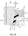
この構成を有するプラスチック製注射器外筒12の成形作業の1段階を図1Aに示す。図のように、金型の内側コア36の外面48と下型32と上型34の内面33、35は、成形機30の中心軸xに関してθ(シータ)の抜き勾配で配置されている。これによって、内側コア36を完成した注射器外筒12の内部からDの方向に引き抜く際に、注射器外筒本体14の内面15と内側コア36の外面48との間に干渉が起こらないようにすることが可能となる。図1Aは、内側コア36を注射器外筒12から引き抜いている間の各部集合を示している。説明の目的のために、角度θは図1Aにおいては、一般的な注射器外筒のそれより幾分誇張されていることに留意されたい。 One stage of the molding operation of the
プラスチック製注射器プランジャ124の成形作業の1段階を図1Bに示す。図のように、金型内側コア54の外面348と、下型50と上型52の内面51、53は、成形機49の中心軸xに関して、抜き勾配Φ(ファイ)で配置されている。これによって、成形された注射器プランジャ124を下型50の中に画定された成形空間55からDの方向に引き抜く際に、プランジャ本体125の外面323と下型50の内面51の間で干渉が起こらないようにすることが可能となる。図1Bは、プランジャ324を成形空間55から引き抜いている間の各部集合を示している。説明の目的のために、角度Φは図1Bにおいて、一般的な注射器のプランジャのそれより幾分誇張されていることに留意されたい。 One stage of the plastic syringe plunger 124 molding operation is shown in FIG. 1B. As shown in the figure, the outer surface 348 of the
12などの注射器外筒または、本明細書に記載の他の任意の注射器外筒またはその他の容器が成形された後、そこに、SiOxバリア層および/またはSiwOxCyの潤滑または疎水性またはその他の表面改質層を設けることが望ましい場合が多く、これらについては、2010年11月25日に米国特許出願公開第2010/0298738 A1号明細書として公開され、2011年7月26日に発行された米国特許第7,985,188号明細書に詳しく説明されている。これらの公開公報と特許を、適当なバリア、潤滑および表面改質層ならびに、それらをどのようにすれば形成できるかを示すために参照することにより、本願に援用する。12 syringe barrel such or after any other syringe barrel or other container as claimed is formed herein, there, lubricating or hydrophobic of SiOx barrier layer and / or Siw Ox Cy It is often desirable to provide a surface modification layer or other surface modification layer, which was published as US Patent Application Publication No. 2010/0298738 A1 on Nov. 25, 2010, and issued on Jul. 26, 2011. U.S. Pat. No. 7,985,188 issued to U.S. Pat. These publications and patents are incorporated herein by reference to show suitable barrier, lubrication and surface modification layers and how they can be formed.
成形後、所定量の液体薬品を患者に投与するために注射器から押し出すための注射器用ブランジャを含む完成品が組み立てられる。プランジャは、外筒の円筒形の本体の中に摺動可能に配置される。プランジャは理想的には、注射器外筒の内径と略同じ外径を有し、それらの間で摺動可能な係合が行われるのと同時に、プランジャと外筒の間の間隙から液体薬品が漏れないようになっている。一般的には約1°〜3°である一般的なプラスチック製注射器外筒とプランジャの抜き勾配により、この点において問題が生じる可能性があり、これは、それによって外筒および/またはプランジャの内径にばらつきが生じるからである。これを補償するために、いくつかの対策をとることができる。たとえば、プランジャを、外筒の円筒形の本体の中で摺動する際にそれが変形できるような弾性材料で形成してもよい。弾性プランジャの外径は、注射器外筒の内径のばらつきを補償するのに十分に大きくする。プランジャが太すぎると、注射器外筒との干渉が生じ、これによって、プランジャを注射器外筒内で移動させるのに、より大きな力が必要となる。弾性プランジャを有する注射器の場合にプランジャにより大きな力が必要となることに対応するための1つの方策として、潤滑層の形成があり、たとえばシリコンオイルを注射器外筒の内部および/またはプランジャに塗布することによって、外筒内でのプランジャの摺動を滑らかにし、摺動しやすくする。図10はこの種の潤滑層を利用した注射器の問題の1つを示している。図のように、層の材料、図10の例ではシリコンオイルはプランジャによって移動可能である。時間が経つと、および/またはプランジャが摺動すると、一般にシリコンオイルの一部が移動して、最終的に層が不均一となる。その結果、その後はプランジャが摺動しにくくなる。さらに、潤滑材料の一部が薬品と一緒にシリンジから押し出されることがあり、場合によっては、その投薬を受ける患者の体内に注入される可能性がある。そのため、プラスチック成形による注射器は使い捨て用とされることが多い。 After molding, a finished product is assembled that includes a syringe blanker for extruding from the syringe to administer a predetermined amount of liquid drug to the patient. The plunger is slidably disposed in the cylindrical main body of the outer cylinder. The plunger ideally has an outer diameter that is approximately the same as the inner diameter of the syringe barrel, and at the same time a slidable engagement is made between them, liquid chemicals are allowed to flow from the gap between the plunger and the outer cylinder. It is designed not to leak. A common plastic syringe barrel and plunger draft angle, typically between about 1 ° and 3 °, can cause problems in this respect, which can cause problems with the barrel and / or plunger. This is because the inner diameter varies. Several measures can be taken to compensate for this. For example, the plunger may be formed of an elastic material that can be deformed when sliding in the cylindrical body of the outer cylinder. The outer diameter of the elastic plunger is made large enough to compensate for variations in the inner diameter of the syringe barrel. If the plunger is too thick, there will be interference with the syringe barrel, which will require more force to move the plunger within the syringe barrel. One approach to address the need for greater force on the plunger in the case of a syringe with an elastic plunger is the formation of a lubrication layer, for example applying silicone oil to the inside of the syringe barrel and / or to the plunger Thus, the sliding of the plunger in the outer cylinder is made smooth and easy to slide. FIG. 10 illustrates one problem with syringes that utilize this type of lubrication layer. As shown, the layer material, silicon oil in the example of FIG. 10, can be moved by the plunger. Over time and / or as the plunger slides, a portion of the silicone oil generally moves, eventually resulting in a non-uniform layer. As a result, the plunger is less likely to slide thereafter. In addition, a portion of the lubricating material may be pushed out of the syringe with the drug and in some cases may be injected into the body of the patient receiving the medication. For this reason, plastic molded syringes are often used for single use.
プラスチック製注射器外筒および/またはプランジャに抜き勾配をつけることに起因する他の問題は、投薬中に外筒に加えなければならない圧力が不均一となる点である。外筒の壁の内径が徐々に小さくなりおよび/またはプランジャの壁の外径が徐々に大きくなるため、プランジャが注射器の針先端に近づくにつれて加えるべき圧力の量を大きくしなければならない。これは投薬が途中で止まってしまう原因となりえ、それによって投薬を受ける患者に苦痛を与える可能性がある。これに加えて、自動注射器、すなわち、たとえばばね仕掛けまたはモータを利用して投薬する機械的器材を使って薬剤を投与する場合も問題となりかねず、それは、これらの器材が、人間が投薬するように容易には抵抗の変化を知覚できないことがあるからである。 Another problem resulting from drafting the plastic syringe barrel and / or plunger is the non-uniform pressure that must be applied to the barrel during dosing. As the inner diameter of the barrel wall gradually decreases and / or the outer diameter of the plunger wall gradually increases, the amount of pressure to be applied must be increased as the plunger approaches the needle tip of the syringe. This can cause medication to stop prematurely, which can be painful to the patient receiving the medication. In addition, it may be a problem to administer drugs using automatic syringes, i.e. mechanical equipment that dispenses, e.g. using spring-loaded or motors, as these equipment are administered by humans. This is because the resistance change may not be easily perceived.
この分野でのその他の先行特許としては、米国特許第5,141,430号明細書、同第5,022,563号明細書、同第5,971,722号明細書がある。 Other prior patents in this field include US Pat. Nos. 5,141,430, 5,022,563, and 5,971,722.
ガラス製注射器およびその他の容器は従来、ガラスの方が未処理のプラスチックより気密性があり、事前充填された内容物に対して不活性であることから、熱化可塑性プラスチック製注射器や容器より好まれている。また、その従来の用途により、ガラスはよく受け入れられており、それは、医学的検体または医薬品調剤等と接触した時に、比較的無害であることが知られているからである。ガラス製注射器はまた、押出成形チューブから製造され、これは抜き勾配を必要としない。しかしながら、特定の塗布物をガラス容器から除去することが望ましく、それによって割れる可能性があり、製造コストが高くなるが、プラスチック容器は、通常の使用ではほとんど壊れず(壊れたとしても、ガラス管のように容器の残骸から鋭利な破片ができず)、多目的金型を用いた射出成形の製造コストは安価であるため、有利である。前述の問題を除去するために、抜き勾配を設けないか部分的に設けずに多用途金型で射出成形することにより形成できるプラスチック製注射が求められている。 Glass syringes and other containers are traditionally preferred over thermally plastic syringes and containers because glass is more airtight than untreated plastic and is inert to prefilled contents. It is rare. Also, because of its conventional use, glass is well accepted because it is known to be relatively harmless when in contact with medical specimens or pharmaceutical preparations and the like. Glass syringes are also manufactured from extruded tubes, which do not require drafting. However, it is desirable to remove certain coatings from the glass container, which may break and increase manufacturing costs, but plastic containers are hardly broken in normal use (even if broken, glass tubes In this way, sharp debris cannot be formed from the remnant of the container), and the manufacturing cost of injection molding using a multipurpose mold is low, which is advantageous. In order to eliminate the aforementioned problems, there is a need for a plastic injection that can be formed by injection molding with a versatile mold with no draft or partial draft.
本発明の一態様は、固体成形品の成形方法である。 One aspect of the present invention is a method for molding a solid molded product.
キャビティを画定する実質的に剛性の表面と実質的に剛性のコアを含む多用途射出成型機が提供される。キャビティとコアは、それらの間に成形空間を画定する。キャビティとコアの少なくとも一方は、分割軸に沿って他方に関して移動可能であり、それによって成形後の成形品を取り出すために成形空間が開く。キャビティまたはコアの少なくとも一部は、小さい抜き勾配の要素である。小さい抜き勾配の要素は、本明細書においては、分割軸に関して抜き勾配が0.5度以下xxxの要素と定義される。分割軸に関して0.5度以下の抜き勾配は、本明細書において、小さい抜き勾配と定義される。 A versatile injection molding machine is provided that includes a substantially rigid surface defining a cavity and a substantially rigid core. The cavity and the core define a molding space between them. At least one of the cavity and the core is movable with respect to the other along the split axis, thereby opening a molding space for removing the molded part after molding. At least a portion of the cavity or core is a small draft element. Small draft elements are defined herein as elements having a draft of less than 0.5 degrees xxx with respect to the split axis. A draft of 0.5 degrees or less with respect to the split axis is defined herein as a small draft.
この方法は、小さい抜き勾配の要素の少なくとも一部を第一の選択温度まで加熱して、それを膨張させるステップを含む。加熱前、加熱中または加熱後に、流体成形材料が成形空間内に射出される。第一の成形材料の少なくとも表面は、小さい抜き勾配の要素と接するように成形され、小さい抜き勾配の形成面が画定される。少なくともこの小さい抜き勾配の形成面が固化され、小さい抜き勾配の固体形成面が得られる。 The method includes heating at least a portion of the low draft element to a first selected temperature to expand it. The fluid molding material is injected into the molding space before, during or after heating. At least the surface of the first molding material is shaped to contact a low draft element to define a low draft forming surface. At least the surface with the low draft is solidified to obtain a solid surface with a small draft.
この方法は、小さい抜き勾配の要素の少なくとも一部を、第一の選択温度より低い第二の選択平均温度まで冷却するステップを含む。十分な冷却を行い、小さい抜き勾配の要素の少なくとも一部を小さい抜き勾配の固体形成面から離れるように十分に熱収縮させ、小さい抜き勾配の要素が小さい抜き勾配の形成面から離れるようにする。この方法では、キャビティとコアを分割軸に沿って分割するステップと、固体成形品を成形空間から取り外すステップが続く。本発明の他の態様は、上記の方法によって作製される注射器アセンブリである。 The method includes cooling at least a portion of the small draft element to a second selected average temperature that is lower than the first selected temperature. Provide sufficient cooling to sufficiently heat shrink at least a portion of the low draft element away from the small draft solid forming surface so that the small draft element leaves the small draft surface . In this method, a step of dividing the cavity and the core along the dividing axis and a step of removing the solid molded product from the molding space are followed. Another aspect of the invention is a syringe assembly made by the method described above.
本発明のまた別の態様は、外筒とピストンを含む注射器アセンブリである。外筒は、略円筒形の側壁を含む。側壁は、液体を収容するための内腔を画定する、実質的に剛性の熱可塑性材料から作製される。内腔の軸方向の抜き勾配は0〜0.5度、任意選択的に少なくとも実質的にゼロ度である。ピストンは前縁面、後縁面、内腔の中に移動可能に設置されるように構成された側縁を有する。側縁は、実質的に剛性の熱可塑性材料から作製される。 Yet another aspect of the present invention is a syringe assembly including an outer cylinder and a piston. The outer cylinder includes a substantially cylindrical side wall. The sidewall is made from a substantially rigid thermoplastic material that defines a lumen for containing liquid. The axial draft of the lumen is 0-0.5 degrees, optionally at least substantially zero degrees. The piston has a leading edge surface, a trailing edge surface, and a side edge configured to be movably disposed within the lumen. The side edges are made from a substantially rigid thermoplastic material.
本発明のさらにまた別の態様は、注射器プランジャまたは同様の成形品に、プラズマ強化化学蒸着法を使用して選択的にコーティングする方法であり、この方法は、以下のように実行される。 Yet another aspect of the present invention is a method of selectively coating a syringe plunger or similar molded article using plasma enhanced chemical vapor deposition, which is performed as follows.
注射器外筒の内容物と接触するように位置付けられた略円形の前部と、注射器外筒と摺動可能に接触するようになされた略円筒形の側部を有する注射器が提供される。前方開口部と、前方開口部から延びる内部側壁を有する略管状のプランジャホルダが提供される。 A syringe is provided having a generally circular front portion positioned to contact the contents of the syringe barrel and a generally cylindrical side portion adapted to slidably contact the syringe barrel. A generally tubular plunger holder having a front opening and an inner sidewall extending from the front opening is provided.
プランジャをプランジャホルダの中に設置し、その際、プランジャの前部がプランジャホルダの前方開口部に面し、プランジャの側部がプランジャホルダの内部側壁と接触するような向きとする。プランジャの前部を、層形成反応ガスと接触させ、プランジャの前部に隣接するプランジャホルダの中にプラズマを生成する。その結果、プラズマ強化化学蒸着法を用いて、プランジャの前部にバリア層が選択的に堆積する。 The plunger is placed in the plunger holder, with the front of the plunger facing the front opening of the plunger holder and the side of the plunger in contact with the inner wall of the plunger holder. The front of the plunger is brought into contact with the layering reaction gas and a plasma is generated in the plunger holder adjacent to the front of the plunger. As a result, a barrier layer is selectively deposited on the front of the plunger using plasma enhanced chemical vapor deposition.
本発明のまた別の態様は、注射器プランジャに選択的にコーティングする別の方法である。 Yet another aspect of the invention is another method of selectively coating a syringe plunger.
注射器外筒の内容物と接触するように位置付けられた略円形の前部と、注射器外筒と摺動可能に接触するようになされた略円筒形の側部と、略円形の後部を有する注射器プランジャが提供される。注射器プランジャを、プラズマ強化化学蒸着チャンバ内に設置する。略円形の前部と略円形の後部の少なくとも一方にマスキングする。これは、プランジャの略円筒形の側部の少なくとも一部には少なくとも実質的にマスキングしないことによって行う。プランジャの側部は、層形成反応ガスと接触させる。プランジャの側部に隣接する蒸着チャンバ内にプラズマが生成される。その結果、プラズマ強化化学蒸着法を用いて、プランジャの側部上に層が選択的に形成される。 A syringe having a generally circular front positioned to contact the contents of the syringe barrel, a generally cylindrical side configured to slidably contact the syringe barrel, and a generally circular rear portion. A plunger is provided. A syringe plunger is placed in the plasma enhanced chemical vapor deposition chamber. Mask at least one of a substantially circular front portion and a substantially circular rear portion. This is done by at least substantially not masking at least a portion of the generally cylindrical side of the plunger. The side of the plunger is brought into contact with the layer forming reaction gas. Plasma is generated in the deposition chamber adjacent to the side of the plunger. As a result, a layer is selectively formed on the side of the plunger using plasma enhanced chemical vapor deposition.
本発明のその他の態様は、下記の本発明の説明と付属の特許請求の範囲から明らかとなるであろう。 Other aspects of the invention will be apparent from the following description of the invention and the appended claims.
本明細書においては、以下の参照番号を使用する。それぞれの図において同様の番号が付与された部品は、対応する要素を示す。 In this specification, the following reference numbers are used. Parts to which similar numbers are assigned in the respective drawings indicate corresponding elements.

上記の説明では、特定の用語は便宜のために使用されており、限定のためではない。「前」、「後」、「上」、「底」等の単語は、参照する図面の中の方向を指す。この用語は、上で具体的に示した単語、その派生形および同様の意味の単語を含む。これに加えて、不定冠詞(“a”)や「1つの」という単語は、特にことわりがない限り、言及されている項目の1つまたは複数を含むと定義される。2つ以上の項目の列挙、たとえば「A、BまたはC」につく「少なくとも〜の1つ」という語句は、A、BまたはCの個々のいずれかの1つおよびその任意の組み合わせを意味する。 In the above description, certain terms are used for convenience and not for limitation. Words such as “front”, “back”, “top”, “bottom”, etc. refer to directions in the referenced drawing. This term includes the words specifically listed above, derivatives thereof and words of similar meaning. In addition, the indefinite article ("a") and the word "one" are defined to include one or more of the items mentioned, unless otherwise specified. An enumeration of two or more items, for example, the phrase “at least one of” on “A, B, or C” means any one of A, B, or C, and any combination thereof. .
図2は、成形された注射器110の一例を示す。図のように、注射器110は、注射可能な薬剤を収容するための内部116を画定する実質的に円筒形の本体114を有する外筒112を含む。外筒ハブ118が外筒112の上から延び、針120を取り付けられるようになっている。針120は、外筒ハブ118と係合する針基122を含む。カラー128は、外筒112から開放端126の付近で半径方向に外側に延び、使用者は注射器110を使用して薬剤を注射する際にこれを握る。プランジャ124は、外筒114の内部116の中に摺動可能に配置され、その開放端126から突出する。プランジャ124は、円筒形本体125と、円筒形本体125の一端を閉鎖する基底部127と、円筒形本体125から基底部127の反対の端で半径方向の外側へと延びるカラー129を含む。 FIG. 2 shows an example of a molded
本発明の一態様は、その内面の抜き勾配が実質的に、または完全にない製品、たとえば注射器外筒112を成形する方法に関する。図3〜6は、図2の注射器外筒112を成形するための成形作業の一実施形態を示す。まず図3を参照すると、本発明による金型130が示されている。図のように、金型130は、下型132と、上型134と、内側コア136を含む。下型132は、円筒形本体114と外筒ハブ118の外面を画定する形状の成形キャビティ138を画定する。内側コア136は、成形キャビティ138の中に適合する大きさと形状であり、円筒形本体114と外筒ハブ118の内面を画定する。上型134は下型132の上に載り、内側コア136を受ける開口部140を有する。上型134の開口部140の付近の円周方向の溝142は、カラー128を画定する形状である。図のように、下型132と上型134と内側コア136は、図3に示される構成に組み立てられると、それらの間に成形材料146を受けるための成形空間144を共同で画定する。成形空間144は実質的に、金型130を用いて製造されることになる所望の注射器外筒112の形状を有する。 One aspect of the present invention relates to a method of forming a product, such as a
引き続き図3を参照すると、本発明による成形作業の第一の段階が示されている。下型132と上型134と内側コア136は、所望の注射器外筒112の形状に成形空間144を画定するように組み立てられる。内側コア136と、任意選択的に下型132と上型134は、成形材料146を成形空間144内に注入する前に加熱される。内側コア136と、任意選択的に下型132と上型134の加熱時間を短縮して、エネルギーコストを最小化し、金型のこれらの部分を形成する材料への、材料疲労の原因となりうる応力を最小化しても。図3に示される構成では、下型132と上型134と内側コア136の間の実質的な空隙だけで成形空間144を画定している。内側コア136と下型132と上型134は各々、当業界で公知のいずれの手段でも加熱できる。たとえば、これら要素は、加熱コイルを用いて誘導加熱してもよく、これはたとえば米国特許出願第2009/0239023号明細書に記載されており、同出願を、その全文がここに記載されているかのように、参照によって本願に援用する。 With continued reference to FIG. 3, the first stage of the molding operation according to the present invention is shown. The
内側コア136の外面148は、図3においては円筒形である。そのため、外面148は、成形空間144の中心軸xに平行である。したがって、内側コア136の引抜きを容易にするための抜き勾配が実質的にない。これに対して、注射器外筒112のための一般的な金型は、円筒形ではなく若干円錐形であり、直径は内側コア136の上に近づくにつれて増大し、下に向かって減少する。図1Aは、一般的な成形方式の拡大詳細図を示し、この構成では外筒の壁が注射器外筒112の中心軸xに関して角度θで配置されている。 The
内側コア136は好ましくは、少なくとも部分的に、ゼロより大きい抜き勾配(θ)を必要とせずに、完成した注射器外筒112を取り出すことができるように選択された熱膨張率を有する1つまたは複数の材料で形成され、これについて以下に詳しく説明する。 The
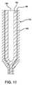
図11は、上述の方法により注射器外筒112を成形するための内側コア136の一実施形態を示す。図のように、内側コア136は、外側膨張層160、伝導層162、内側層164および中央冷却チャネル166を含む。外側膨張160層は、その熱膨張率に基づいて選択された材料で形成される。一実施形態において、外側膨張層160は鋼、たとえばH13工具鋼で形成される。異なる材料も、外側膨張層160の厚さ、所望の空隙150、使用可能な材料の熱膨張率に応じて使用できる。伝導層162は、外側膨張層160に関して内側に配置され、その伝導特性に基づいて選択される材料で形成される。一実施形態において伝導層162は銅で形成される。伝導層162、所望の空隙150、使用可能な材料の伝導率に応じて、特定の種類の銅またはその他の材料を選択できる。内側層164は、伝導層162の内側に配置され、外側膨張層160と同じ材料または、内側コア136の加熱冷却サイクルに耐えられる他の材料で形成してもよい。中央冷却チャネル166は、内側層164の内側に、内側コア136の中央部分に沿って配置される。中央冷却チャネル166は、成形コアを冷却するための冷却剤を受けるように構成することができる。冷却チャネルには、当業界で公知の任意の適当な構成を利用でき、たとえば米国特許第5,573,787号明細書または米国特許第7,303,387号明細書により開示されたものがあり、これらの特許を、全文が記載されているかのように、参照によって本願に援用する。 FIG. 11 shows one embodiment of an
内側コア136は、選択された成形温度まで加熱されると、その外面148が注射器外筒112の円筒形本体114とハブ118の内面115の所望の寸法となる大きさまで膨張するような大きさである。 The
図4では、成形材料146が成形空間144の中に注入されている。成形材料146は好ましくは熱可塑性高分子材料、たとえば環状オレフィンコポリマ(COC)、ポリエチレンテレフタレート(PET)またはポリプロピレン(PP)等である。成形材料146は、その溶融点を上回るまで加熱され、成形空間144が完全に満たされるように流れる。熱は、内側コア136を加熱し、任意選択的に下型132および/または上型134を加熱して供給してもよい。任意選択的に、追加的な加熱源も使用してよい。COCまたはPPを成形材料146として使用する1つの好ましい実施形態において、内側コア136の成形温度は160℃〜210℃の間である。下型132および/または上型134もまた、任意選択的に、この温度まで加熱してもよい。あるいは、これらの部分を異なる温度まで加熱することができる。一実施形態において、内側コア136と任意選択的に下型132および/または上型134の成形温度は、成形材料146の流れを制御するように選択される。他の実施形態において、コア136を加熱する温度を、それと上型134と下型132の間のすべての空隙がなくなるようにするのに必要な最低限として、成形作業中に繰り返し行われる加熱と冷却により発生する材料の疲労を最小化する。 In FIG. 4, the
成形作業の次の段階を図5に示す。この段階では、内側コア136が冷却される。この冷却によって、内側コア136が収縮し、その外径D1が、好ましくは実質的に等しい円筒形本体114と金型上型34の開口部140の内径D2より小さくなる(図5参照)。これにより今度は、内側金型コア136と円筒形本体114の内面115の間および上型134の開口部140と内側コア136の間に空隙150ができ、これは図5Aに詳しく示されている。内側コア136は好ましくは、少なくとも、内側コア136と円筒形本体114の間、または内側コア136と上型134の開口部140の間に生じる可能性のあるいずれの干渉も除くのに十分に収縮し、そこから注射器外筒114を引き抜くことができるような温度まで冷却される。一実施形態において、内側コア136は、10μmの空隙150ができる温度まで十分に冷却される。他の実施形態において、内側コア136は、15μmの空隙150ができる温度まで十分に冷却される。他の実施形態において、内側コア136は、金型130の大きさ、成形材料146の種類、最終製品の形状等の要素に応じて、より大きい、またはより小さい空隙ができる温度まで冷却できる。任意選択的に、下型132と上型134を内側コア136と同時に冷却してもよい。また、任意選択的に、内側コア136および、おそらくは下型132と上型134の冷却は、成形材料146がその溶融点またはガラス転移点(Tg)未満に冷却されるのに十分な程度としてもよい。成形材料146は好ましくは、引抜き前にそのガラス転移点以下に冷却される。好ましい実施形態において、内側コア136の全体を均一な速度で冷却し、成形材料146の均一な硬化を促進する。同様に、上型134と下型132の各々は、均一な速度で冷却してもよい。他の好ましい実施形態において、内側コア136、下型132、上型134のすべてを同じ均一な速度で冷却する。同様に、内側コア134、下型132、上型136のほか、含められ得る任意の他の金型部分を任意に組み合わせて均一な速度で冷却してもよい。他の実施形態において、金型部分のいずれかの冷却速度を利用して、成形材料146が硬化する速度を制御し、完成時の注射器外筒112に所望の特性を持たせる。 The next stage of the molding operation is shown in FIG. At this stage, the
図6は、成形作業の引抜き段階を示す。図のように、成形材料146は完全に固化されて、完成後の注射器外筒112が画定されている。内側コア136は、それをDの方向に移動させることによって、円筒形本体114の内部116から容易に引き抜かれる。上型134は同様に、それをDの方向に移動させることによって下型132から取り外され、その後、外筒112は、それをDの方向に移動させることによって下型132の成形キャビティ138から引き抜くことができる。一実施形態において、成形キャビティ138と上型134の開口部140に、注射器外筒112をそこから引き抜くことができるように、抜き勾配(θ)をつける。あるいは、下型132および/または上型134を複数の部品として形成できる。図7は他の実施形態(サイドドロー)の引抜き段階を示しており、下型132と上型134の各々が、2つの部品132A、132B、134A、134Bとして形成されている。 FIG. 6 shows the drawing stage of the molding operation. As shown, the
本発明の他の態様は、その外面に実質的に抜き勾配をつけない製品、たとえば注射器プランジャ124を成形する方法に関する。図12〜15は、図2の注射器プランジャ124のための成形作業のある実施形態を示す。まず図12を参照すると、本発明による金型230が示されている。図のように、金型230は下型232、上型234、内側コア236を含む。下型232は、円筒形本体125と基底部127の外面を画定する形状とされた成形キャビティ238を画定する。内側コア236は、成形キャビティ238の中に適合する大きさと形状であり、円筒形本体125と基底部127の内面を画定する。上型234は下型232の上に載り、内側コア236を受ける開口部240を含む。上型234の開口部240付近の円周方向の溝242は、カラー129を画定する形状である。図のように、下型232、上型234、内側コア236は、図12に示される構成に組み立てられると、それらの間に、成形材料246を受けるための成形空間244を共同で画定する。成形空間244は実質的に、金型230を使用して製造される予定の所望の注射器プランジャ124の形状を有する。 Another aspect of the present invention relates to a method of molding a product, such as a
引き続き図12を参照すると、本発明による成形作業の第一の段階が示されている。下型232、上型234、内側コア236を組み立て、所望の注射器プランジャ124の形状に成形空間244を画定する。下型232と、任意選択的に内側コア236と上型234を、成形材料246を成形空間244に注入する前に加熱する。下型232と、任意選択的に内側コア236と上型234の加熱時間を短縮して、エネルギーコストを最小化し、金型のこれらの部分を形成する材料への、材料疲労の原因となりうる応力を最小化してもよい。図12に示される構成では、下型232、上型234、内側コア236の間の実質的な空隙だけで金型空間244が画定される。内側コア236、下型232、上型234の各々は、当業界で公知のいずれの手段でも加熱できる。たとえば、これら要素は、加熱コイルを用いて誘導加熱してもよく、これはたとえば米国特許出願公開第2009/0239023号明細書に記載されており、同出願を、その全文がここに記載されているかのように、参照によって本願に援用する。 With continued reference to FIG. 12, the first stage of the molding operation according to the present invention is shown. The
下型232の内面233は、図12においては円筒形である。そのため、内面233は成形空間244の中心軸に平行である。したがって、完成したプランジャ124を成形空間244から抜き出しやすくするための角度は実質的につけられていない。これに対して、図2に示される種類の注射器プランジャのための一般的な金型の同様の下型の内面は、円筒形ではなく若干円錐形であり、直径は下型の上に近づくにつれて増大し、下に向かって減少するであろう。図1Bは、一般的な成形方式の拡大詳細図を示しており、図中、プランジャの壁はプランジャ124の中心軸xに関して角度Φで配置されている。 The
下型232は好ましくは、少なくとも部分的に、抜き勾配をつけることなく完成したプランジャ124を取り出すことができるように選択された熱膨張率を有する1つまたは複数の材料から形成され、これについて以下に詳しく説明する。たとえば、下型232は鋼、たとえばH13工具鋼で形成し、または部分的に形成することができる。下型232にはさらに、その伝導性に基づいて選択された材料、たとえば銅を含めることができる。 The
下型232は、選択された形成温度まで加熱されると、その内面233がプランジャ124の円筒形本体125と基底部127の外面223の所望の寸法となる大きさまで膨張するような大きさである。
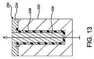
図13では、成形材料246が成形空間244に注入されている。成形材料246は好ましくは、熱可塑性高分子材料、たとえばPPまたはCOCである。成形材料246は、その融点を超えるまで加熱され、成形空間244を完全に満たすように流れる。熱は、下型232を加熱し、任意選択的に内側コア236および/または上型234を加熱することによって供給してもよい。任意選択的に、追加的な加熱源も使用してよい。COCまたはPPを成形材料146として使用する1つの好ましい実施形態において、下型232の成形温度は160C〜210Cの間である。内側コア236および/または上型234もまた、任意選択的に、この温度まで加熱してもよい。あるいは、これらの部分を異なる温度まで加熱することができる。一実施形態において、下型232と任意選択的に内側コア236および/または上型234の成形温度は、成形材料246の流れを制御するように選択される。他の実施形態において、下型232を加熱する温度を、それと上型234の間のすべての空隙がなくなるようにするのに必要な最低限として、成形作業中に繰り返し行われる加熱と冷却により発生する材料の疲労を最小化する。 In FIG. 13, the
成形作業の次の段階を図14に示す。この段階では、下型232が冷却される。この冷却により、下型232が収縮し、その内径D3は円筒形本体125の外径D4より大きくなる。これによって今度は、下型232と円筒形本体125の外面123の間に空隙250ができ、それが図14Aに詳しく示されている。下型232は好ましくは、少なくとも、下型232と円筒形本体125の間で発生しうる干渉のすべてがなくなるように十分に収縮し、それゆえ、注射器プランジャ124を成形キャビティ238から引き抜くことができるような温度まで冷却する。一実施形態において、下型232は、10μmの空隙250ができる温度まで十分に冷却される。他の実施形態において、下型232は、15μmの空隙250ができる温度まで十分に冷却される。他の実施形態において、下型232は、金型230の大きさ、成形材料の種類、最終製品の形状等の要素に応じて、より大きい、またはより小さい空隙ができる温度まで冷却することができる。任意選択的に、内側コア236と上型234は、下型232と同時に冷却してもよい。また、任意選択的に、下型232と、おそらくは内側コア236と上型234の冷却は、成形材料246がその溶融点またはガラス転移点未満に冷却されるのに十分な程度としてもよい。成形材料246は好ましくは、引き抜く前にそのガラス転移点(Tg)未満に冷却される。好ましい実施形態において、下型232の全体を均一な速度で冷却して、成形材料246の均一な硬化を促進する。同様に、内側コア236と上他234の各々は、均一な速度で冷却してもよい。他の好ましい実施形態において、内側コア236、下型232、上型234のすべてを、同じ均一な速度で冷却する。同様に、内側コア234、下型232、上型236のほか、含められ得るいずれの追加的成形部分を任意に組み合わせて均一な速度で冷却してもよい。他の実施形態において、金型部分のいずれかの冷却速度を利用して、成形材料246が硬化する速度を制御し、完成後の注射器プランジャ124に所望の特性を持たせる。 The next stage of the molding operation is shown in FIG. At this stage, the
図15は、成形作業の引抜き段階を示す。図のように、成形材料246は完全に固化され、完成後の注射器プランジャ124が画定されている。上型234は、それをDの方向に移動させることによって、下型232から取り外し、プランジャ124は、それを方向Dに移動させることによって、下型232の中に画定された成形キャビティ238から容易に引き抜かれる。一実施形態において、上型234の開口部240には、それをプランジャのカラー129から取り外せるように、抜き勾配がつけられる。あるいは、上型234は、図7の注射器外筒112を成形するための上型の実施形態と同様に、複数の部品として形成することができる。 FIG. 15 shows the drawing stage of the molding operation. As shown, the
本発明の他の態様は、その外面に部分的に抜き勾配がつけられていない製品、たとえば注射器プランジャ424の成形方向に関する。図16は、図15に示される引抜き段階と同様の、このような実施形態の成形作業の引抜き段階を示す。図のように、中型437が下型432と上型434の間に設置されている。下型432は、円筒形のプランジャ本体425の下側部分のみを形成するものであり、中心軸xに平行な内面433を有し、完成したプランジャ424を引き抜くためにその内面433につける抜き角度が最小化されるか、不要となる程度に十分に収縮できるように選択された熱膨張率を有する材料で形成される。中型437は、そのように選択された熱膨張率を有する材料で形成しなくてもよい。図16に示される実施形態において、中型437は完成後のプランジャ424を取り外しやすいように、2つの部分437A、437Bとして形成される。あるいは、中型437には、抜き角度をつけるか、または取り外しやすくするためのその他の方法で構成してもよい。図16の実施形態には、成形機のうち、選択された熱膨張率を有する材料を用いて形成される相対的割合が最小化し、したがってコストが削減されるという利点がある。この点において、任意選択的に、下型432の大きさを最小化することにより、コストを最小化することができる。一実施形態において、下型432は交換可能な構成要素として、材料が疲労し、成形中に確実に接触するまで膨張できなくなったら廃棄し、交換できるように構成される。この実施形態によれば、下型432の大きさを最小化して、下型432の交換時のコストを最小化できる。 Another aspect of the invention relates to the molding direction of a product, such as a
図17は、図15と16に示される引抜き段階と同様の、本発明による注射器プランジャ524の成形作業の別の実施形態の引抜き段階を示す。図のように、図17のプランジャ524は上記のものとは、それがカラーを持たない点で異なる。下型532は、図16の下型432と同様に構成され、円筒形本体525の下側部分のみを形成する。下型532の内面533は、中心軸xに平行であり、完成したプランジャ524を引き抜くためにその内面533につける抜き角度が最小化されるか不要となる程度に十分に収縮できるように選択された熱膨張率を有する材料で形成される。図17の成形作業は図16のそれと、中型がないという点で異なり、また図16で単一の部品として形成されている上型534は下方に延びて下型532の上部と接触し、図16の実施形態の上および中型の両方に代わるものとなっている。上型534の内面535は、中心軸xに関して抜き勾配Φで設置され、プランジャ524の本体525は上方向に向かって内側に先細となっている。上型534はそれゆえ、図17に示されるように、方向Dに移動させることによって、完成したプランジャ524から取り外すことができる。この実施形態にはまた、成形機のうち、選択された熱膨張率を有する材料で形成される相対的な割合が最小化され、それゆえコストが削減されるという利点がある。この点において、任意選択的に、下型532の大きさを縮小することによって、なるべくコストを低く抑えることができる。一実施形態において、下型532は交換可能な構成要素として、材料が疲労し、成形中に確実に接触するまで膨張できなくなったら廃棄し、交換できるように構成される。この実施形態によれば、下型532の大きさを最小化して、下型532の交換時のコストを最小化できる。 FIG. 17 shows an extraction stage of another embodiment of the molding operation of the
図16と17のプランジャ424、524は、他のすべての点において、図12〜15と同様に構成し、製造することができる。 The
本発明の他の態様は、上述の外筒112および/またはプランジャ124、424、524のための成形方法の1つまたは複数を使用して、注射器110を製造する方法に関する。一実施形態において、外筒112とプランジャ124、424、524の各々を上述の方法の1つにしたがって成形し、組み立てて、注射器110、たとえば図2に示されるものを製造する。 Another aspect of the invention relates to a method of manufacturing a
一実施形態によれば、図3〜7の外筒112を図12〜15のプランジャ124と組み立てて、注射器を製造する。このような実施形態によれば、円筒形外筒本体114の内径とプランジャの円筒形本体125の外径は実質的に等しくてもよい。円筒形の外筒本体114の内面115とプランジャの円筒形本体125の外面123の各々には、実質的に抜き勾配がつけられず、プランジャ124を外筒112内で容易に摺動させることができる。 According to one embodiment, the
他の実施形態によれば、図3〜7の外筒112を図16のプランジャ424または図17のプランジャ524と組み立てて、注射器を製造する。このような実施形態によれば、下型432、523により形成されるプランジャの円筒形本体425、525の外面423、523の第一の部分423A、523Aは、実質的に抜き勾配と継ぎ目がつけられておらず、外筒の円筒形本体114の内面115と接触する。円筒形の外筒本体414の外面の第一の部分423A、523Aの内径とプランジャの円筒形のプランジャ本体125の外径は実質的に等しい。プランジャ424、524は外筒112の内部で容易に摺動できる。図16の実施形態では中型437によって、または図17の実施形態では上型534によって形成されるプランジャの円筒形本体425、525の外面423、523の第二の部分423B、523Bの直径は第一の部分423A、523Aより小さいため、これは外筒の円筒形本体414の内面115と接触せず、外筒112の中でのプランジャ424の摺動を妨害しない。 According to other embodiments, the
一実施形態によれば、注射器110は、潤滑剤コーティングを設けずに、上述の実施形態のいずれかにおいて説明したように組み立てられる。外筒の円筒形本体114とプランジャの円筒形本体125、425、525の直径が合致し、そこに抜き勾配がつけられていないことから、プランジャ124、424、524は外筒112の内部で摺動しやすいため、潤滑剤コーティングは不要である。本発明の他の実施形態において、潤滑コーティングを設けて、さらに摺動しやすくすることができる。 According to one embodiment, the
本発明の他の実施形態によれば、複数の外筒112と複数のプランジャ124、424、524を組み立てることによって、複数の注射器を製造する。外筒の円筒形本体114の各々の内径と各プランジャの円筒形本体125、425、525の各々またはプランジャの円筒形本体425、525の外面423、523の第一の部分423A、523Aのみの外径を成形後に測定し、各外筒112を、外筒の円筒形本体125、425、525の内径に実質的に最も近い外径を有する円筒形本体125、425、525を有するプランジャ124、424、524とマッチさせる。これによって、外筒112内でのプランジャ124、424、524の摺動能力が最適化される。 According to another embodiment of the present invention, a plurality of syringes are manufactured by assembling a plurality of
一実施形態において、外筒112とプランジャ124、424、524は、金型130、430、530からロボット制御で取り外される。これによって、手作業で取り外す場合に生じる可能性のある傷その他の欠陥の発生が防止され、外筒112の中でのプランジャ124、424、524の摺動能力がさらに最適化される。 In one embodiment, the
本発明の他の態様は注射器に関し、これは、上述の方法の1つまたは複数にしたがって製造される充填済み注射器であってもよい。注射器は、さまざまな構成とすることができる。一実施形態において、注射器は、米国特許出願第61/359,434号明細書において開示されているように構成および/または製造される。本発明による注射器は充填済み注射器として使用するのに特に有利であり、これは、上で詳しく述べたように、プランジャ124、424、524の外径と外筒112の内径を実質的に等しくすることができ、漏れの原因となりうるそれらの間の空隙を完全になくすことができるからである。 Another aspect of the invention relates to a syringe, which may be a prefilled syringe manufactured according to one or more of the methods described above. The syringe can have various configurations. In one embodiment, the syringe is constructed and / or manufactured as disclosed in US patent application Ser. No. 61 / 359,434. The syringe according to the present invention is particularly advantageous for use as a prefilled syringe, which makes the outer diameter of the
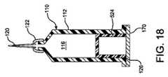
本発明による充填済み注射器の一実施形態を図18と19に示す。図の注射器110は、図3〜7にしたがって製造された外筒112と図17にしたがって製造されたプランジャ524を含む。図18は、プランジャ524が外筒112内に収容された、組立後の充填済み注射器110を示す。箔または薄いプラスチック層として形成できるシール材170が外筒112の開放端126を覆うように取り付けられ、充填済み注射器110の中に収容される製品が滅菌状態に保持される。注射器110の中に収容される製品を投与する前に、図19に示されるように、シール材170を取り外す。図18と19に示される注射器110のプランジャ524は、プランジャ524を押す際の助けとなるカラーを含んでいないため、押し具172を別の要素として提供することができる。シール材170を取り外した後に、図19に示されるように、押し具172をプランジャ524の中に挿入する。押し具172は、図19に示されるように組み立てた場合に、注射器の端から突出するカラー174を含み、これによって注射器110の使用者はプランジャ524を、それを圧迫することによって方向Pに押して、注射器110の中に収容された製品を投与することができる。 One embodiment of a prefilled syringe according to the present invention is shown in FIGS. The illustrated
他の実施形態において、注射器110は、図18と19に示されるものと同様に、充填済みの密閉された器材として提供できるが、押し具172は省くことができる。本発明によるプランジャの、図12〜16に示されるような他の実施形態を、図18と19に示されるプランジャの代わりに使用することができる。 In other embodiments, the
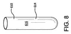
本発明の方法は、上では注射器の外筒とプランジャに関して説明したが、内側コア部分を有する金型を使用して形成される他のさまざまな製品にも利用できる。たとえば、管状の形状または中空の内部を有する他の製品を、上述のものと同様の方法によって形成できる。当業者であれば、上記の説明に基づき、成形機の構成への改変を思いつくであろう。図2は、上述のものと同様の工程を用いて形成される試験管610を示す。図のように、試験管610は、内部616を画定する円筒形本体614を有する。図9は、このような試験管610のための、本発明による成形作業の1段階を示し、その中で、完成した試験管610が成形機630から取り外される。図のように、金型630は図3〜6に関して上述したものと同様であるが、成形空間644の形状が試験管610のそれに対応しており、丸い閉鎖した底部652が含まれ、これに対して図3〜6の底部652は注射器10を使って投与される薬剤の通路となる開口部を画定する。他の実施形態において、下型632および/または上側の位置634は、図7の実施形態のそれと同様の方法で、2つ以上の部品として提供することができる。 Although the method of the present invention has been described above with respect to a syringe barrel and plunger, it can also be used with a variety of other products formed using a mold having an inner core portion. For example, other products having a tubular shape or hollow interior can be formed by methods similar to those described above. Those skilled in the art will be able to conceive modifications to the configuration of the molding machine based on the above description. FIG. 2 shows a
本発明の他の態様は、注射器110(図1〜9および18〜19)、310(図20〜25)または1282(図35)に関し、各々、任意選択的に上記にしたがって成形される。本発明の発明者は、上述の成形方法がいずれのタイプの注射器の作製にも有益であると明確に考えている。 Other aspects of the invention relate to syringe 110 (FIGS. 1-9 and 18-19), 310 (FIGS. 20-25) or 1282 (FIG. 35), each optionally shaped according to the above. The inventor of the present invention clearly believes that the molding method described above is beneficial for making any type of syringe.
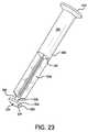
図20〜25を参照すると、注射器アセンブリ310は、略円筒形の側壁314を含む外筒312を有する。側壁314は、この実施形態においては実質的に剛性の熱可塑性材料で作製されるが、側壁314はあるいは、熱硬化性材料、ガラス、金属、その他の材料または材料の任意の組み合わせによって作製でき、これらに限定されない。側壁314は、液体を収容する内腔316を画定する。 Referring to FIGS. 20-25, the
注射器アセンブリ310は、前縁面320、後縁面322、内腔316の中に移動可能に設置されるように構成された側縁324を有するピストン318(図21〜23に示される)を含む。図の実施形態において、ピストン318は、その側縁324を含め、実質的に剛性の熱可塑性材料で作製されるが、ピストン318はあるいは、熱硬化性材料、ガラス、金属、その他の材料または材料の任意の組み合わせによって作製でき、これらに限定されない。特に、実質的に剛性の材料で作製する代わりに、少なくとも側縁324を弾性材料で作製し、ピストン318の残りの部分の材料と共成形するか、別の部品として提供し、組み立ててもよい。別の弾性ピストン表面またはプランジャ先端324をより剛性のコアまたはプランジャ本体と組み立てたものを提供することが当業界で知られている。
好ましくは、潤滑剤326をピストン318の側縁324、内腔314またはその両方に堆積させる。特に好ましい実施形態において、潤滑剤326は、たとえば本明細書で説明するように、PECVDにより堆積させる。 Preferably,
図の実施形態において、ピストン前縁面320は凸状である。外筒312の、吐出開口部344の付近の部分の形状と相補的な形状を有する凸状の前縁面320が特に想定され、それによってピストンの前縁面320が吐出開口部344に向かって奥まで進められた時に、これらの部品の間に囲まれる容積が小さくなり、吐出が完了した後に注射器310の中に残っている吐出材料の量が限定される。 In the illustrated embodiment, the piston leading
図の実施形態において、ピストンの後縁面322は凹状である。後縁面322はあるいは、どのような形状でもよいが、凹状のピストン後縁面を凸状の前縁面320と組み合わせ、またピストン318を比較的薄くすることによって、ピストン318の作製に使用される材料の量を削減することが有利となることもある。さらに、比較的薄く、湾曲したピストン318は、より厚い円筒形のピストンより柔軟性が高く、外筒312の中でより移動しやすく、外筒内で前進する際に、外筒312またはピストン318の真円度のわずかな凹凸に適合できることが想定される。 In the illustrated embodiment, the piston trailing
図の実施形態において、ピストンの側縁324には内腔316からの空隙がある。空隙は、注射器アセンブリ310の内容物が側縁324の外に漏れるのを防止するのに十分に小さくなくてはならないが、ピストン318が注射器外筒の中で滑らかに摺動するのに十分に大きくするべきである。この半径方向の空隙は好ましくは、比較的剛性の側縁324については、一般的に締り嵌めの状態となる(部品が組み立てられた時の空隙が略ゼロである)弾性のプランジャ先端にとって一般的なものより大きい。弾性のプランジャ先端は、プランジャ先端が外筒内で前進できるように撓まなければならず、この撓みによってピストン318と外筒312の間の摩擦が増大する。この実施形態では、プランジャと注射器外筒の間の空隙は、好ましくは約10〜約15μm(マイクロメートル)である。 In the illustrated embodiment, the
外筒312の内腔316につけられる軸方向の抜き勾配θ(シータ)は好ましくは、図1Aに示されるように0°〜0.5°(すなわち、ゼロ〜30分角)、任意選択的に0°〜0.25°、任意選択的に0°〜0.16°、任意選択的に0°〜0.06°、任意選択的に0°〜0.03°、任意選択的に0°〜0.014°、任意選択的に0°〜0.01°、任意選択的に実質的または正確にゼロ度である。受け入れられる抜き勾配はひとつには、引込長さ、すなわち注射器の形状によって可能なかぎり内容物を完全に吐出させる時の注射器外筒に沿ったピストン318の移動長さに依存する。 The axial draft θ (theta) applied to the
公称の抜き勾配(θ)とその誤差は、ピストン318と注射器外筒の間の空隙が、引込長さ、すなわち注射器外筒312に沿ったピストン318の移動長さにわたり、10μm〜15μmの間となるような大きさとすることができる。それゆえ、空隙の変化は、引込長さにわたって5μmとすることができる。たとえば、上記の抜き勾配によって、ピストン318と外筒318の(各々の側の)空隙は、「引込長さ」の表に示されるように変化する。 Nominal draft angle (θ) and its error is such that the gap between
それゆえ、たとえば、抜き勾配θが均一に0.16°である時、引込長さにわたるピストン318と外筒312の間の空隙の変化は14μmである。抜き勾配(θ)の正接は、空隙の変化を引込長さで割ったものと等しい。長い引込長さにわたって抜き勾配が大きいと、最小空隙は、ピストンの移動開始時に、比較的大きな量だけ増大する(抜き勾配が正であり、流体を引き込む場合と反対に、シリンジから吐出させるものと仮定)。それゆえ、引込長さが長ければ、抜き勾配は小さい方が望ましい。また、抜き勾配がゼロであることはどの引込長さにも適当であり、それによってピストン318と外筒312の間の空隙は均等となる。 Therefore, for example, when the draft angle θ is uniformly 0.16 °, the change in the gap between the
注射器外筒の内部には抜き勾配が正またはゼロであることが好まれるが、同じ数値と範囲の負の抜き勾配でも、抜き勾配が吐出開始時に最少となることを除き、吐出中の空隙の変化は同じとなる。 It is preferred that the draft angle is positive or zero inside the syringe barrel, but even with negative drafts of the same value and range, the draft is minimal at the beginning of the dispense, except that the draft is minimized. The change will be the same.
外筒312のうち、ピストン318が移動する部分は、注射器310により供給される内容物の量に依存するであろう。一般に、外筒312のうち、ピストン318が移動する部分は、外筒312の全長より実質的に小さくなるであろう。使い捨ての充填済み注射器の場合、製造者は、供給するべき内容物を外筒312のどの程度まで充填するかに応じて、外筒312のうち、ピストン318が移動する部分を有効に決定するであろう。充填済み注射器の、完全に引き込んだピストン318の後方では、空隙が前述のものより大きい場合がある。実際、完全に引き込んだピストンの後方の空隙を大きくすることは、外筒312の後部を開くことによって組み立て中にピストン318を外筒312の中に挿入しやすくするために望ましい。その結果、抜き勾配は、完全に引き込まれたピストン318の後方において、その側方または前方より大きくすることができる。 The portion of the
任意選択的に、ピストンの側縁324は、これらの図面、特に図21に示されているように、軸方向の面において凸状である。側縁324のこの湾曲によって、側縁324と外筒312の間の接触面積が小さくなり、それゆえ、摺動摩擦が減少し、または側縁324と外筒312の一部がその一方または両方の表面の凹凸により引っかかる可能性が減少する。 Optionally, the
図の実施形態において、外筒312は射出成形による単一の熱可塑性部品(任意の潤滑層またはその他の層は別とする)である。これは、製造しやすさの点で有利であるが、不可欠ではなく、その代わりに2部式または多部式の外筒もまた想定される。たとえば、皮下注射針346を取り付けるためのハブを別の部品として提供することができ、あるいはルア、ルアロック、またはその他のタイプの連結手段を皮下注射針346と外筒312の間に設けることもできる。任意選択的に、成形された単一の熱可塑性部品の各々は、1つの均一な材料で作製される。しかしながら、ここでもまた、部品の1つまたは複数を複合、異種または層状材料で作製する別の実施形態も想定される。 In the illustrated embodiment, the
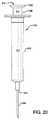
特に図21〜23を参照すると、任意選択的に、ピストン318を、ピストン318を内腔316の中で前進させるためのステムまたはプッシュロッド328と組み合わせる。任意選択的に、ピストン318とステム328は射出成形による単一の熱可塑性部品であるが、これらは任意選択的に、2つ以上の部品として提供することもできる。任意選択的に、成形された単一の熱可塑性部品の各々は、1つの均一な材料で作製される。しかしながら、ここでもまた、部品の1つまたは複数を複合、異種または層状材料で作製する別の実施形態も想定される。たとえば、ピストン318とステム328を画定する熱可塑性材料の成形では、より滑りやすい材料をまず注入して、外筒312の中でピストン318を前進させやすくすることができる。 With particular reference to FIGS. 21-23, optionally, the
図の実施形態において、ステム328は、ピストン318に連結された第一の端部330と、それと反対の、外筒312から突出する第二の端部332を有する。ステム328の、その第一と第二の端の間の部分は、管状部334を有し、その内腔316からの最大の半径方向の空隙は1mm未満である。図の実施形態において、ステム328の管状部334は、その第二の端部332に隣接している。管状部334は、ピストン318が外筒312の中で前進する際に、ステム328とピストン318が歪まないような大きさとし、そのように位置付けることができる。 In the illustrated embodiment, the
これに加えて、図の実施形態において、ステム328の、その第一と第二の端部330、332の間の部分は、略十字形断面部分336を有する。この実施形態では、ステム328の十字形断面部分336は、その第一の端部330に隣接する。図の実施形態において、管状部334の閉鎖端342は、ステム328の略十字形断面部分336と融合する。 In addition, in the illustrated embodiment, the portion of the
ステム328の、その第一の端部330とその略十字形断面部分336の間の部分は、内腔316の直径の半分より小さい直径を有するロッド部338を有する。しかしながら、この直径の制限は重要ではなく、直径をこれより大きく、または小さくすることができる。管状部334は開放端340と、注射器外筒の中に配置される閉鎖端342を有する。 The portion of the
図の実施形態において、外筒312は吐出開口部344を有し、注射器アセンブリはさらに、吐出開口部344に動作的に連結される皮下注射針346を含む。 In the illustrated embodiment, the
注射器外筒とピストンは、PECVD(プラズマ強化化学蒸着法)によって処理し、(1)外筒および/またはプランジャのバリアコーティング、(2)外筒および/またはプランジャの潤滑コーティング、または(3)たんぱく質の吸着を抑制するための外筒またはプランジャの表面改質を提供することができる。注射器外筒のPECVD処理は、2010年11月25日に米国特許出願公開第2010/0298738 A1号明細書として公開され、2011年7月26日に発行された米国特許第7,985,188号明細書に記載されており、これらを参照によって本願に援用する。注射器プランジャのPECVD処理を以下に説明する。 The syringe barrel and piston are processed by PECVD (Plasma Enhanced Chemical Vapor Deposition), (1) Barrier coating on the barrel and / or plunger, (2) Lubricant coating on the barrel and / or plunger, or (3) Protein It is possible to provide surface modification of the outer cylinder or the plunger for suppressing the adsorption of the water. The PECVD process for syringe barrels was published as U.S. Patent Application Publication No. 2010/0298738 A1 on Nov. 25, 2010 and U.S. Pat. No. 7,985,188 issued on Jul. 26, 2011. Which are described in the specification and are incorporated herein by reference. The PECVD process of the syringe plunger is described below.
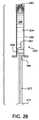
ここで図26〜35を参照し、部分的または全体的に管中において気密状態で摺動可能な注射器用ピストンまたはその他の構造上にPECVD層を提供するための実施形態を説明する。これらの実施形態は、図2の124などのピストンまたはプランジャ、図10A〜10Cのプランジャ、図18〜19のプランジャ524、図20〜25のピストン318、図26〜30のプランジャまたは略円筒形の成形品1258、図31、32、34、35のストッパ1282、または図33のセプタム1310のいずれに層を設けるのにも適している。 Referring now to FIGS. 26-35, an embodiment for providing a PECVD layer on a syringe piston or other structure that can be slid in an airtight manner in a tube partially or entirely will be described. These embodiments include pistons or plungers such as 124 of FIG. 2, plungers of FIGS. 10A-10C,
図26と28を参照すると、本発明を実施できる一般的な注射器1252は、内面1254、開放端1256、プランジャ1258、前端1260を有する注射器外筒1250を含む。注射器外筒1250には、任意選択的に、内容物1264を充填することができる。注射器プランジャまたはプランジャ1258は、略円形の前部1262、略円筒形の側部1266、略円形の後部1268、およびプランジャロッドを有する。図の実施形態は、任意選択的に、この実施形態においては側部1266の一部である隆起した、任意選択的に一体構造とされたピストンリング1274と1276と、この実施形態においては周辺前部1262である面取り部1278を有する。前部1262は、プランジャ1258の中の、注射器の内容物1264があれば通常それと接触している部分として定義される。 Referring to FIGS. 26 and 28, a
プランジャの前部1262にはバリア層1280を設けて、特に充填済み注射器1252の場合に、プランジャ1258の成分が注射器の内容物1264の中に浸出すること、またはその逆を防止することが望ましい。一般的なSiOxのバリア層1280とその形成方法は、たとえば、2010年11月25日に米国特許出願公開第2010/0298738 A1号明細書として公開され、2011年7月26日に発行された米国特許第7,985,188号明細書に詳しく説明されている。この公開公報と特許を、適当なバリアおよび潤滑層とそれを形成できる方法を示すために、参照によって本願に援用する。しかしながら、場合により、側部1266にSiOx層を設けないことが望ましいこともある。 It is desirable to provide a
同様に、側部1266に滑りやすい層、または潤滑層を設けて、注射器1252の内容物を吐出させる時のように、外筒1250の中でプランジャ1258を前進させるために必要な押出力と摺動力を軽減させることが望ましい。しかしながら、場合により、プランジャ1258の前部1262には滑りやすい層を設けないままとして、その層の成分が注射器1252の内容物の中に漏出するのを防止することが望ましいこともある。 Similarly, a slippery layer or a lubrication layer is provided on the
したがって、この方法により、どの実施形態においても、加工物、たとえばプランジャ1258に形成される層をカスタマイズし、コーティングしたい部分にコーティングし、コーティングするべきでない部分には層を設けないようにすることができる。 Thus, in this embodiment, in any embodiment, the layer formed on the workpiece, eg,
プラズマ強化化学蒸着法を用いて注射器プランジャ1258に選択的に層を形成するための本発明の実施形態による方法を図27と28に示す。注射器外筒1250の内容物1264と接触するように位置付けられた略円形の前部1262と、注射器外筒1250と摺動可能に接触するようになされた略円筒形の側部1266を有する注射器プランジャ1258が提供される。前方開口部1082と、前方開口部1082から延びる内部側壁1088を有する略管状のプランジャホルダ1080が提供される。 A method according to an embodiment of the present invention for selectively forming a layer on
注射器プランジャ1258をプランジャホルダ1080の中に設置し、その際、注射器プランジャ1258の前部がプランジャホルダ1080の全方開口部1082に面し、注射器プランジャ1258の側部1266がプランジャホルダ1080の内部側壁1088と接触するような向きとする。 The
注射器プランジャ1258の前部を、層形成反応ガスと接触させる。プラズマを、プランジャホルダ1080の中の、注射器プランジャ1258の前部1262の付近で生成する。条件は、プラズマ強化化学蒸着法を用いて、注射器プランジャ1258の前部1262に選択的にバリア層1280を堆積させるような条件とする。 The front of the
このようにしてコーティングされた成形品を他の構成要素と組み立てることができ、たとえばいずれかの実施形態による略円筒形の成形品1258とプッシュロッド1270とのアセンブリがある。一代替形態として、プランジャ1258を、少なくとも1層1280の堆積中にプッシュロッド1270に固定することができる。 The molded article thus coated can be assembled with other components, such as a generally cylindrical molded
略円筒形の成形品1258と、注射器外筒1250およびプッシュロッド1270とのアセンブリも想定される。 An assembly of a generally cylindrical shaped
略円筒形の成形品1258と、注射器外筒1250、プッシュロッド1270およびエンドキャップ1260とのアセンブリも想定される。 An assembly of a generally cylindrical shaped
略円筒形の成形品1258と、注射器外筒1250、プッシュロッド1270、および皮下注射針とのアセンブリも想定される。 An assembly of a generally cylindrical shaped
略円筒形の成形品1258と、注射器外筒1250、プッシュロッド1270、皮下注射針および針シールドとのアセンブリも想定される。上記のいずれのアセンブリにおいても、略円筒形の成形品1258は外筒1250の中で摺動可能なプランジャとして機能するように構成できる。注射器外筒1250は、任意選択的に、その内部もPECVDで処理する。 An assembly of a generally cylindrical shaped
この方法を実行するための代表的な装置が図27に示されており、これは、容器ホルダ1050、対電極1108、外部電極1160、電源1162を含むPECVD装置を提供する。プランジャ1258を所定の位置に置かれるように容器ホルダ1050にセットされたプランジャホルダ1080は、プラズマ反応チャンバを画定し、これは任意選択的に、真空チャンバとすることができる。プランジャ1258が下方に引っ張られないように、母指押圧部1272を、任意選択的に、プランジャホルダ180の開放端(126)、プランジャホルダ1080の内部段差、または突起と引掛けるか、その他の方法でホルダに関して拘束することができる。真空源1098と反応ガス源1144を提供してPECVDを促進することができる。 A representative apparatus for performing this method is shown in FIG. 27, which provides a PECVD apparatus that includes a
いずれの実施形態のPECVD装置も、その代わりに大気圧PECVD用に使用でき、この場合、プラズマ反応チャンバが真空チャンバとして機能する必要はない。 The PECVD apparatus of either embodiment can instead be used for atmospheric pressure PECVD, in which case the plasma reaction chamber need not function as a vacuum chamber.
図27に示される実施形態において、容器ホルダ1050は、容器ポートに設置された容器の中にガスを供給するためのガス取入ポート1104を含む。ガス取入ポート1104は摺動シール材1106を有し、これは、円筒形プローブ1108がガス取入ポート1104から挿入された時に、プローブ1108と接するように設置できる。プローブ1108は、その遠位端1110がガス供給ポートまで延びるガス取入管とすることができる。図の実施形態の遠位端1110をプランジャホルダ1080の中に挿入し、1つまたは複数のPECVD反応物質およびその他のプロセスガスを供給することができる。 In the embodiment shown in FIG. 27, the
図18と19はそれゆえ、プラズマ強化化学蒸着法を用いて、略円筒形の成形品1258の端部1262に選択的に層を形成する方法を実行するための装置を示す。この方法にはいくつかのステップを含めることができる。端部1262と略円筒形の側面部1266を有する略円筒形の成形品1258が提供される。第一の開口部1298を有し、第一の開口部1298から延びる内腔1300を画定するホルダ1080が提供される。成形品1258は、少なくとも部分的に内腔1300の中に設置され、その際、その端部1262がホルダ1080の第一の開口部1298に面し、その側部1266が内腔と接触する向きとする。1280等の少なくとも1層が、供給源1144により供給される少なくとも1つの層形成前駆体のプラズマ強化化学蒸着によって、成形品1258の端部1262に選択的に形成される。 FIGS. 18 and 19 therefore show an apparatus for performing the method of selectively forming a layer at the
任意選択的に、プッシュロッド1270はさらに、母指押圧パッド1272を含む。母指押圧パッド1272は、少なくとも部分的に内腔1300の中に、たとえば内腔1300内の空隙が小さくなるように適合する大きさとすることができる。 Optionally,
プラズマ強化化学蒸着法は、たとえば、特に図27および同様の図31と35に関して実行でき、そのためにホルダ1080の第一の開口部1298を、真空源1098と前駆体ガスの供給源1144を含むPECVD装置に動作的な関係でセットしてから、その少なくとも1層1280を堆積させる。 Plasma enhanced chemical vapor deposition can be performed, for example, with particular reference to FIG. 27 and similar FIGS. 31 and 35, for which purpose PECVD includes a
任意選択的に、成形品1258を少なくとも部分的に内腔1300の中に設置して、成形品と内腔のアセンブリを形成してから、ホルダ1080の第一の開口部1298をPECVD装置の上に設置する。成形品と内腔のアセンブリは、内腔の中に収容された成形品1258を保護し、コーティングされるべき表面が成膜前に汚染されるのを予防し、成膜後に部品を扱う際に層1280に損傷が及ぶことを予防する。成形品と内腔のアセンブリを形成した後、成形品と内腔のアセンブリをPECVD装置の上に設置する前に、成形品と内腔のアセンブリをPECVD装置に搬送することができ、そのような搬送中に成形品を保護することができる。 Optionally, the molded
少なくとも1層を堆積した後に、成形品と内腔のアセンブリを、任意選択的に組み立てた状態のまま取り外し、PECVD装置から搬送することができる。 After the deposition of at least one layer, the molded article and lumen assembly can be optionally removed and transported from the PECVD apparatus.
任意選択的に、略円筒形の成形品1258は、成形品と内腔のアセンブリをPECVD装置から搬送した後に、成形品と内腔のアセンブリから取り外すことができる。内腔が一方の端で第一の開口部1298において、他方の端で第二の開口部1314において開放している場合、略円筒形の成形品1302は、それを第一の開口部1298から押し出すことによって、成形品と内腔のアセンブリから取り外すことができる。これは、たとえば物体を第二の開口部から内腔1300の中に挿入して行うことができる。 Optionally, the generally cylindrical molded
図29〜30に示される本発明の他の態様は、注射器プランジャ1258の側部に選択的に層を形成する方法である。組み立てられた注射器1252の中で注射器外筒1250の内容物と接触するようになされた略円形の前部1262を有する注射器プランジャ1258が提供される。プランジャ1258は、注射器外筒1250(図26)と摺動可能に接触するようになされた略円筒形の側部1266と、略円形の後部1268を有する。図29はまた、略円筒形の成形品1258が任意選択的に、プッシュロッド1270に固定され、層形成ステップ中にホルダ1294に支持され、任意選択的に、プッシュロッドを扱うことによってホルダ1294から取り外すことができることを示している。注射器プランジャは小さな部品であり、層形成および組立作業中には、これらを取り扱わないことが望ましい。プッシュロッド1270には層形成や特別な取り扱いが不要であるため、加工中にプランジャ1258を取り扱うために便利に使用される。 Another aspect of the invention shown in FIGS. 29-30 is a method for selectively forming a layer on the side of a
注射器プランジャ1258は、プラズマ強化化学蒸着チャンバ1290の中に設置することができる。略円形の前部1262と略円形の後部1268の少なくとも一方(ここでは両方)に、図29に示されるマスク1292またはシート1294と同様にマスキングし、注射器プランジャ1258の少なくとも略円筒形の側部1266には、少なくとも実質的にマスキングを施さない。 The
注射器プランジャ1258の側部1266を、層形成反応ガスと接触させる。プラズマが、蒸着チャンバ1290の中の注射器プランジャ1258の側部1266の付近で生成される。層1296が、プラズマ強化化学蒸着法を用いて、注射器プランジャ1258の側部1266に選択的に堆積される。 The
図29はそれゆえ、プラズマ強化化学蒸着法を用いて、略円筒形の成形品1302の側部1266に選択的に層形成するための方法を実行するのに有益な装置を示している。この方法にはいくつかのステップを含めることができる。相反する側にある端部1262、1268と略円筒形の側部1266を有する略円筒形の成形品1258が提供される。成形品1258を、プラズマ強化化学蒸着チャンバ1290の中に設置する。端部1262と1268の少なくとも一方、ここでは両方の少なくとも一部にマスキングし、側部1266はマスキングしないままとする。少なくとも1つの層1296が、層形成前駆体のプラズマ強化化学蒸着によって成形品1258のマスキングされていない側部1266に選択的に堆積される。 FIG. 29 therefore illustrates an apparatus useful for performing a method for selectively layering the
任意選択的に、略円筒形の成形品1258の端部1262の全部でない部分をコーティングすることができる。これは、これは、たとえば端部1262のいくつかの部分を覆わないマスク1292を設けることによって実行できる。たとえば、マスク292を適当に選択し、設置することにより、略円筒形の成形品1258の中央端部をコーティングすることができ、略円筒形の成形品1258の周辺端部1278をコーティングしないままとすることができる。 Optionally, a portion of the
図29〜30の実施形態において、装置は、略円筒形の成形品1258の、端部1262に隣接する側部1266をコーティングするように構成されている。しかしながら、任意選択的に、装置は、マスク1292からスカートを下方に延ばすことによって、側部1266の隣接部すなわち上部である側部にマスキングするか、あるいは側部1266の全体をマスキングするように構成することができる。 In the embodiment of FIGS. 29-30, the apparatus is configured to coat the
他の変形形態では、略円筒形の成形品1258の、隣接部から遠位側の、図29の方向では下方の側部1296をコーティングしないまま残すことができる。これは、たとえばマスクとサポート1294を側部1266の下側部分1296と接するように、または側部1266の全部と接するように上方に延ばすことによって実行できる。 In other variations, the generally cylindrical shaped
次に、図31と32の実施形態を参照すると、他のタイプの容器閉鎖栓、ここでは、尿検体採取管またはバイアルに使用されるような単純なストッパ1302に層形成するための、図27のそれと同様の装置が示されている。 Referring now to the embodiment of FIGS. 31 and 32, FIG. 27 illustrates a layering on a
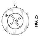
図33は、薬剤バイアルまたはその他の容器を永久的に封止するための特定用途ストッパであるセプタム1310の側部1316に選択的に層形成するための装置を示す。この例では、略円筒形の成形品1310が容器のセプタムである。セプタム1310は、その端部1312と1320には高低がつけられ、容器を開封することなく、皮下注射針で穿刺して容器の内部を吸引できるようになされた薄い膜1322を有する。膜1322は針によって穿刺可能であり、その後、針を抜くと穿刺された部分は元のように閉じて、容器は再度密閉される。 FIG. 33 shows an apparatus for selectively layering on the
側部1316は、中央端部1312を覆うマスク1324、端部1320および隣接する側部1330を覆うマスク1326、周辺端部1332を覆うマスク1328の1つまたは複数でマスキングした状態でこれに対してPECVDを実行することにより、選択的にコーティングされる。中央端部1312に隣接し、周辺端部1332から遠い側部1316の覆いを取り、図33に示される構造を取り囲むPECVD装置のチャンバ内でコーティングすることができる。従来通りに、換気用通路を、たとえば換気通路1334または多孔質マスクとして設け、コーティングするべき成形品とマスクの間に捕捉されたエアポケットが、マスキングされた成形品に真空をかけた時に排出されるようにすることができる。 The
マスク1324は、セプタムまたはその他の略円筒形の成形品1310の端部1312と結合するように構成された部分1336を有する。同様に、マスク1326は、セプタムまたは略円筒形の成形品1310の端部1320と結合するように構成された部分1336を有する。マスク1326と略円筒形の成形品1310の端部1320は、全体が接触する実質的に同じ形状の結合部を有する。しかしながら、マスク1324は、端部1312と比較して実質的に同じ形状の結合部を持たず、これは端部1312が環状で、陥凹部を取り囲んでおり、これはマスク1324に追従しない、またはそれと結合しないからである。
任意選択的に、ホルダまたはマスク1326には、複数または多数の略円筒形の成形品を受けるための、1336などの2つ以上の部分または開口部を設けることができるため、すべてをPECVD装置の中で一度にコーティングできる。マスク1326には、少なくとも1層、たとえば1318のために、複数の略円筒形の成形品1310を受け、それにマスキングするように構成された複数のウェル1336を有する表面1340を設けることができる。 Optionally, the holder or
複数のウェルまたは開口部は、少なくとも1層のために、複数の略円筒形の成形品を受けるためのパターンを形成することができる。任意選択的に、1324と1328などのマスクは繰り返し設置でき、また、任意選択的に、合体させてホルダ内の開口部と位置合わせされたマスクを有するテンプレートを形成することもできる。 The plurality of wells or openings can form a pattern for receiving a plurality of generally cylindrical shaped articles for at least one layer. Optionally, masks such as 1324 and 1328 can be placed repeatedly, and optionally can be combined to form a template having a mask aligned with the opening in the holder.
同様に、図29のマスク1292とホルダ1294を増やして、1回の蒸着ステップで同時に複数の略円筒形の成形品1258を処理することができる。 Similarly, by increasing the number of
図31と32は、略円筒形の成形品1282が容器ストッパとすることができ、これらがストッパホルダ1080の中に保持され、その肩部により、真空をかけた時にストッパ1282がその着座位置(図の通り)より先まで進むのが防止されることを示している。 FIGS. 31 and 32 show that a substantially cylindrical molded
略円筒形の成形品1282と容器のアセンブリが想定される。略円筒形の成形品1282は、容器のストッパとして機能するように構成される。 A generally cylindrical molded
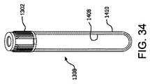
図34〜35は、医療用検体採取管、たとえば真空採血管の実施形態を示しており、その中で、略円筒形の成形品1282は容器閉鎖栓1302のストッパ、たとえば容器ストッパ1282とシールド1304のアセンブリである。この実施形態において、任意選択的に、容器ストッパとシールドのアセンブリ1302は、ストッパ端部1306が内腔1300(図35)の中にあり、シールド1304が少なくとも部分的に内腔1300の外部にある状態で設置することができる。 34-35 show an embodiment of a medical specimen collection tube, such as a vacuum blood collection tube, in which a generally cylindrical shaped
図35に示されるように、略円筒形の成形品1282と容器1308およびシールド1304のアセンブリが想定され、その場合、略円筒形の成形品1282は、容器1308のストッパとして機能するように構成される。容器1308は、任意選択的に、PECVDで処理された内部1408をさらに有する。 As shown in FIG. 35, an assembly of a generally cylindrical shaped
あるいは、容器はバイアルまたはキュベットとすることができる。バイアルまたはキュベットはさらに、PECVDにより処理された内部を含むことができる。 Alternatively, the container can be a vial or cuvette. The vial or cuvette can further include an interior processed by PECVD.
いずれの実施形態においても、層を堆積させる前に、略円筒形の成形品の、コーティングするべき部分に部分真空をかけて、略円筒形の成形品から置換可能な流体材料を抽出するか、硬化させることができる。また、あるいはその代わりに、略円筒形の成形品の、コーティングするべき部分に、たとえば酸素を用いてPECVDによる前処理を行って、コーティングするべき表面を酸化させるか、他の処理を行い、または略円筒形の成形品から除去された移動可能な流体材料を酸化させることができる。この処理は、コーティングするべき領域に限定でき、または、略円筒形の成形品をマスキングするか内腔の中に設置する前に行う、より全体的な処理とすることができる。 In any embodiment, prior to depositing the layer, a partial vacuum is applied to the portion of the generally cylindrical shaped article to be coated to extract the replaceable fluid material from the substantially cylindrical shaped article, It can be cured. Alternatively or alternatively, the part to be coated of the substantially cylindrical shaped part may be pretreated by PECVD, for example with oxygen, to oxidize the surface to be coated, or to perform other treatments, or The movable fluid material removed from the generally cylindrical shaped article can be oxidized. This process can be limited to the area to be coated, or it can be a more overall process performed before masking or placing the generally cylindrical shaped article in the lumen.
いずれの実施形態においても、どのような所望の種類または条件のPECVD層も使用し、または形成できる。たとえば、その少なくとも1層は、たとえば以下に定義するSiOxのバリア層を含むか、その機能を果たして、略円筒形の成形品からコーティングされた部分を通じて材料が浸出するのを減少させることができる。その少なくとも1層は、たとえば後述のSiOxのバリア層を含むか、その機能を果たして、材料がコーティングされた端部を通じて略円筒形の成形品の中へと浸出するのを減少させることができる。 In any embodiment, any desired type or condition of PECVD layer can be used or formed. For example, the at least one layer can include, or function for example, a SiOx barrier layer as defined below to reduce leaching of material through a portion coated from a generally cylindrical shaped article. The at least one layer may include, for example, or serve as a SiOx barrier layer, described below, to reduce leaching of material through the coated end into a generally cylindrical shaped article.
その少なくとも1層は、以下に定義するようなSiwOxCyのSi対O対Cの原子比率を有する疎水性層1280とすることができ、これは、コーティング部分に、その少なくとも1層が暴露される材料と接触するのに望ましい表面疎水性を持たせるようになされる。たとえば、疎水性層は、プランジャ1258、ストッパ1282またはセプタム1310の、薬剤に暴露されることになる部分に使用して、たとえばコーティング表面を安定化させ、または注射器またはストッパの装着された容器の内容物がコーティング表面に付着または凝結することなく、より十分に除去されるようにすることができる。疎水性層の他の用途は、ストッパ1282の露出面上の真空採血管1308の中に受けられた血液の凝集または凝固活性化を阻止することである。The at least one layer may be a
その少なくとも1層は、コーティングされた部分からの常圧気体または流体の進入を阻止するバリアまたは、コーティングされた部分からの材料の漏出を阻止するバリアとすることができる。このようなバリア層は一般に、以下に定義するようにSiOxで形成される。The at least one layer can be a barrier that prevents entry of atmospheric gas or fluid from the coated portion, or a barrier that prevents leakage of material from the coated portion. Such a barrier layer is generally formed of SiOx as defined below.
その少なくとも1層は、浸出防止バリア、疎水性層、表面安定化層、周辺条件に対するバリア、または内容物漏出防止バリアのうちの2つ以上を含んでいてもよく、異なる特性を有する2つ以上の層を設けてもよい。 The at least one layer may include two or more of a leaching prevention barrier, a hydrophobic layer, a surface stabilization layer, a barrier to ambient conditions, or a content leakage prevention barrier, two or more having different properties. These layers may be provided.
たとえば、充填済み注射器または閉鎖された容器(ストッパまたはセプタムで閉鎖される)の場合、以下の1つまたは複数を形成することが有益であることもある、すなわち、
注射器または閉鎖された容器または他の層の内容物がプランジャの中に浸出すること、またはその逆を防止するための浸出防止バリア、
注射器内の材料からの揮発性成分の損失を防止する、内容物漏出防止バリア、
注射器または閉鎖された容器の内容物に対する凝結やその他の不利な影響を防止する疎水性層。For example, in the case of a prefilled syringe or a closed container (closed with a stopper or septum) it may be beneficial to form one or more of the following:
Anti-leach barrier to prevent syringe or closed container or other layer contents from leaching into plunger, or vice versa,
Content leakage prevention barrier that prevents loss of volatile components from the material in the syringe,
A hydrophobic layer that prevents condensation and other adverse effects on the contents of a syringe or closed container.
それゆえ、複数の層を堆積させることができる。たとえば、ある組成および特性を有する第一の層を堆積させ、その後、異なる組成、異なる特性またはその両方を有する第二の層を堆積させることができる。あるいは、ある組成および特性を有する第一の層を堆積させることができ、その後、同じ組成と特性を有する第二の層を堆積させることができる。あるいは、ある組成と特性を有する第一の層を堆積させることができ、その後、異なる組成、特性またはその両方を有する第二の層を堆積させることができ、その後、第一の層と同じ組成と特性を有する第三の層を堆積させることができる。また別の選択肢として、ある組成と特性を有する第一の層を堆積させることができ、その後、第一の層とは異なる組成、特性またはその両方を有する複数の第二の層を堆積させることができ、その後、第一の層と同じ組成と特性を有する第三の層を堆積させることができる。 Therefore, multiple layers can be deposited. For example, a first layer having a composition and properties can be deposited, followed by a second layer having a different composition, different properties, or both. Alternatively, a first layer having a composition and properties can be deposited, followed by a second layer having the same composition and properties. Alternatively, a first layer having a composition and properties can be deposited, followed by a second layer having a different composition, properties, or both, and then the same composition as the first layer A third layer having the characteristics can be deposited. As another option, a first layer having a composition and properties can be deposited, and then a plurality of second layers having a composition, properties, or both different from the first layer are deposited. And then a third layer having the same composition and properties as the first layer can be deposited.
潤滑層は、以下のプロセスガスと入力電力を用いたPECVD工程によって生成される、すなわち、
反応して層を形成する前駆体ガス、
任意選択的に、酸素またはその他の酸化剤、
アルゴンまたはヘリウム等のキャリアガス、
層形成を誘導するのに十分なプラズマ生成電力。The lubrication layer is generated by a PECVD process using the following process gas and input power:
A precursor gas that reacts to form a layer,
Optionally, oxygen or other oxidants,
A carrier gas such as argon or helium,
Sufficient plasma generation power to induce layer formation.
使用される材料と条件は、略円筒形の物体の摺動力または押出力を、コーティングされていない注射器外筒と比較して少なくとも25パーセント減少させるのに有効なものとすることができる。 The materials and conditions used can be effective to reduce the sliding force or push force of a generally cylindrical object by at least 25 percent compared to an uncoated syringe barrel.
いずれの実施形態においても、PECVDに使用される層形成反応ガスは、有機金属前駆体ガスとすることができる。 In any embodiment, the layer forming reaction gas used for PECVD can be an organometallic precursor gas.
本発明のPECVD層の前駆体は、広義では、有機金属前駆体と定義される。有機金属前駆体は、本明細書では、周期表のIII族および/またはIV族に属し、有機残渣、たとえば炭化水素、アミノカーボンまたはオキシカーボン残渣を有する金属元素の包括的な化合物と定義される。ここで定義される有機金属化合物には、珪素またはその他のIII/IV族の金属原子に直接結合される、または任意選択的に、酸素または窒素原子を通じて結合される有機構成成分を有するいずれかの前駆体が含まれる。周期表のIII族の中で関係する元素は、硼素、アルミニウム、ガリウム、インジウム、タリウム、スカンジウム、イットリウム、ランタナムであり、アルミニウムと硼素が好ましい。周期表のIV族の中で関係する元素は、珪素、ゲルマニウム、錫、鉛、チタン、ジルコニウム、ハフニウム、トリウムであり、珪素と錫が好ましい。他の揮発性有機成分も想定できる。しかしながら、本発明の実行には有機珪素化合物が好ましい。 The precursor of the PECVD layer of the present invention is broadly defined as an organometallic precursor. Organometallic precursors are defined herein as generic compounds of metallic elements belonging to group III and / or group IV of the periodic table and having organic residues such as hydrocarbon, aminocarbon or oxycarbon residues. . Organometallic compounds as defined herein are either directly bonded to silicon or other Group III / IV metal atom, or optionally having an organic component bonded through an oxygen or nitrogen atom. A precursor is included. The elements involved in group III of the periodic table are boron, aluminum, gallium, indium, thallium, scandium, yttrium, and lanthanum, with aluminum and boron being preferred. The elements related in the IV group of the periodic table are silicon, germanium, tin, lead, titanium, zirconium, hafnium, and thorium, and silicon and tin are preferable. Other volatile organic components can also be envisaged. However, organosilicon compounds are preferred for the practice of the present invention.
有機珪素前駆体が想定され、「有機珪素前駆体」は本明細書全体を通じて、最も広義に、以下の結合の少なくとも1つを有する化合物と定義される。
上記の第1の構造は、酸素原子と有機炭素原子(有機炭素原子は、少なくとも1つの水素原子と結合した炭素原子である)に連結された四価珪素原子である。上記の第2の構造は、−NH−結合と有機炭素原子(有機炭素原子は、少なくとも1つの水素原子と結合した炭素原子である)に連結された四価珪素原子である。任意選択的に、有機珪素前駆体は、線状シロキサン、単環シロキサン、多環シロキサン、ポリシルセスキオキサン、線形シラザン、単環シラザン、多環シラザン、ポリシルセスキアザンおよび、これらの前駆体のいずれかの2つ以上の組み合わせからなる群から選択される。また、前駆体としては、上記の2つの化学式には当てはまらないが、アルキルトリメトキシシランが考えられる。 The first structure is a tetravalent silicon atom connected to an oxygen atom and an organic carbon atom (the organic carbon atom is a carbon atom bonded to at least one hydrogen atom). The second structure is a tetravalent silicon atom connected to an —NH— bond and an organic carbon atom (the organic carbon atom is a carbon atom bonded to at least one hydrogen atom). Optionally, the organosilicon precursor is a linear siloxane, monocyclic siloxane, polycyclic siloxane, polysilsesquioxane, linear silazane, monocyclic silazane, polycyclic silazane, polysilsesquiazane, and their precursors Are selected from the group consisting of two or more combinations. In addition, as a precursor, alkyltrimethoxysilane may be considered although it does not apply to the above two chemical formulas.
酸素含有前駆体(シロキサン等)が使用される場合、疎水性または潤滑層を形成する条件下でのPECVDによって得られる代表的な予想される実験組成物は、SiwOxCyのSi対O対Cの原子比率で、wが1、式中のxが約0.5〜2.4、yが約0.6〜約3となり、その一方で、バリア層を形成する条件下でのPECVDによって得られる代表的な予想される実験組成物はSiOxとなり、式中のxは約1.5〜約2.9である。窒素含有前駆体(シラザン等)が使用される場合、予想組成はSiw*Nx*Cy*となり、すなわちSiwOxCyの中でOがNに置換され、Oと比較してNがより高原子価となるように適合される(2ではなく3)。後者の適応では一般に、シロキサンのw、x、yの比率をそのアザ等価体の中の対応する原子数に当てはめる。本発明の特定の態様において、Siw*Nx*Cy*、ここでw*、x*、y*が、水素原子の数を任意選択的に変えられることを除き、そのシラキサン等価体のw、x、yと同じと定義される。If an oxygen-containing precursor (such as siloxane) is used, a typical expected experimental composition obtained by PECVD under conditions that form a hydrophobic or lubricious layer is the Siw Ox Cy Si pair. In the atomic ratio of O to C, w is 1, x is about 0.5 to 2.4, and y is about 0.6 to about 3, while the conditions under which the barrier layer is formed A typical expected experimental composition obtained by PECVD is SiOx , where x is from about 1.5 to about 2.9. When a nitrogen-containing precursor (silazane, etc.) are used, the expected composition ofSi w * N x * C y * next, i.e. Siw Ox C O in they is replaced by N, as compared with O N is adapted to be higher valence (3 instead of 2). The latter adaptation generally applies the ratio of w, x, y of siloxane to the corresponding number of atoms in its aza equivalent. In a particular embodiment of the present invention, Siw * Nx * Cy * , where w* , x* , y* are of the siloxane equivalent, except that the number of hydrogen atoms can be optionally changed. It is defined as the same as w, x, and y.
上記の実験式を有する前駆体開始材料の種類の1つは線形シロキサン、たとえば下の化学式を有する材料である。
式中、Rの各々はアルキル、たとえばメチル、エチル、プロピル、イソプロピル、ブチル、イソブチル、t−ブチル、ビニル、アルキンまたはその他から個別に選択され、nは1、2、3、4以上で、任意選択的に2以上である。想定される線形シロキサンのいくつかの例としては、以下がある、すなわち、
ヘキサメチルジシロキサン(HMDSO)、
オクタメチルトリシロキサン、
デカメチルテトラシロキサン、
ドデカメチルペンタシロキサン、
または上記のうちの2つ以上の組み合わせ。上記の構造の中で酸素原子が−NH−に置換される類縁シラザンも、同様の層を形成するために有益である。想定される線形シラザンのいくつかの例は、オクタメチルトリシラザン、デカメチルテトラシラザンまたはこれらのうちの2つ以上である。Wherein each R is individually selected from alkyl, such as methyl, ethyl, propyl, isopropyl, butyl, isobutyl, t-butyl, vinyl, alkyne or others, n is 1, 2, 3, 4 or more, optional Optionally 2 or more. Some examples of possible linear siloxanes include the following:
Hexamethyldisiloxane (HMDSO),
Octamethyltrisiloxane,
Decamethyltetrasiloxane,
Dodecamethylpentasiloxane,
Or a combination of two or more of the above. An analogous silazane in which oxygen atoms are replaced by -NH- in the above structure is also useful for forming a similar layer. Some examples of possible linear silazanes are octamethyltrisilazane, decamethyltetrasilazane, or two or more of these.
V.C.前駆体開始材料の他の種類は単環シロキサン、たとえば下の構造式、
1,3,5−トリメチル−1,3,5−トリス(3,3,3−トリフルオロプロピル)メチル]シクロトリシロキサン、
2,4,6,8−テトラメチル−2,4,6,8−テトラビニルシクロテトラシロキサン、
ペンタメチルシクロペンタシロキサン、
ペンタビニルペンタメチルシクロペンタシロキサン、
ヘキサメチルシクロトリシロキサン、
ヘキサフェニルシクロトリシロキサン、
オクタメチルシクロテトラシロキサン(OMCTS)、
オクタフェニルシクロテトラシロキサン、
デカメチルシクロペンタシロキサン、
ドデカメチルシクロヘキサシロキサン、
メチル(3,3,3−トリフルオロプロピル)シクロシロキサン、
たとえば以下のような環状有機シラザンも想定される。
オクタメチルシクロテトラシラザン、
1,3,5,7−テトラビニル−1,3,5,7−テトラメチルシクロテトラシラザン ヘキサメチルシクロトリシラザン、
オクタメチルシクロテトラシラザン、
デカメチルシクロペンタシラザン、
ドデカメチルシクロヘキサシラザン、または
上記のうちの2つ以上の組み合わせ。V. C. Other types of precursor starting materials are monocyclic siloxanes, such as the structural formula below,
1,3,5-trimethyl-1,3,5-tris (3,3,3-trifluoropropyl) methyl] cyclotrisiloxane,
2,4,6,8-tetramethyl-2,4,6,8-tetravinylcyclotetrasiloxane,
Pentamethylcyclopentasiloxane,
Pentavinylpentamethylcyclopentasiloxane,
Hexamethylcyclotrisiloxane,
Hexaphenylcyclotrisiloxane,
Octamethylcyclotetrasiloxane (OMCTS),
Octaphenylcyclotetrasiloxane,
Decamethylcyclopentasiloxane,
Dodecamethylcyclohexasiloxane,
Methyl (3,3,3-trifluoropropyl) cyclosiloxane,
For example, the following cyclic organic silazanes are also envisaged.
Octamethylcyclotetrasilazane,
1,3,5,7-tetravinyl-1,3,5,7-tetramethylcyclotetrasilazane hexamethylcyclotrisilazane,
Octamethylcyclotetrasilazane,
Decamethylcyclopentasilazane,
Dodecamethylcyclohexasilazane, or a combination of two or more of the above.
V.C.前駆体開始材料の他の種類は多環シロキサン、たとえば下の構造式の中の1つを有する材料である、すなわち、
V.C.多環シロキサン前駆体開始材料の他の種類はポリシルセスキオキサンであり、その実験式はRSiO1.5、構造式は以下のとおりである、すなわち、
V.C.上記の構造の中で−NH−を酸素原子と置換した類縁ポリシルセスキアザンもまた、同様の層を形成するのに有益である。想定されるポリシルセスキアザンの例としては、各Rがメチルのポリ(メチルシルセスキアザン)と、R基の90%がメチル、10%が水素原子のポリ(メチル−ヒドリドシルセスキアザンがある。これらのうちの2つ以上の組み合わせも想定される。 V. C. An analogous polysilsesquiazane in which —NH— is replaced by an oxygen atom in the above structure is also useful for forming a similar layer. Examples of possible polysilsesquiazanes include poly (methylsilsesquiazane) in which each R is methyl and poly (methyl-hydridosilsesquiazane) in which 90% of the R groups are methyl and 10% are hydrogen atoms. Combinations of two or more of these are also envisioned.
V.C.本発明による潤滑層用として特に想定される1つの前駆体は単環シロキサンであり、たとえばオクタメチルシクロテトラシロキサンである。 V. C. One precursor specifically envisaged for the lubricating layer according to the invention is a monocyclic siloxane, for example octamethylcyclotetrasiloxane.
本発明によるバリア層用として特に想定される1つの前駆体は線形シロキサンであり、たとえばHMDSOである。 One precursor specifically envisaged for the barrier layer according to the invention is a linear siloxane, for example HMDSO.
潤滑層または層は、厚さ1000nm未満とし、プラズマ強化化学蒸着法により形成できる。これは、注射器の使用時または容器へのストッパの着脱時に隣接する容器壁または注射器壁と接して摺動するプランジャまたはストッパの摺動面において有益である。 The lubricating layer or layer can be less than 1000 nm thick and can be formed by plasma enhanced chemical vapor deposition. This is beneficial on the sliding surface of the plunger or stopper that slides against the adjacent container wall or syringe wall when using the syringe or when the stopper is attached to or detached from the container.
1つの選択肢として、潤滑層は以下を含む、すなわち、
SiwOxCyまたはSiwNxCyのSi対O/N対Cの原子比率で、wが1、式中のxが約0.5〜2.4、yが約0.6〜約3の層、
潤滑層、容器の熱可塑性の基材、またはその両方の内腔への浸出を減少させるのに有効な量の、潤滑層を覆う表面処理層。As one option, the lubricating layer includes:
Siw Ox Cy or Siw Nx by C Si vs. O / N to C atomic ratio ofy, w is 1, x in the formula is about 0.5 to 2.4, y is about 0.6 ~ About 3 layers,
A surface treatment layer covering the lubricating layer in an amount effective to reduce leaching of the lubricating layer, the container's thermoplastic substrate, or both into the lumen.
潤滑層と表面処理は、押出力(静止しているプランジャまたはストッパを動き出させるための力)、摺動力(移動しているプランジャまたはストッパを移動させ続けるために必要な力)またはその両方が、潤滑層と表面処理がない場合に必要な、それに対応する力より小さくて済むようにするのに有効に構成し、そのような相対量で存在させることができる。潤滑層はまた、表面処理なしに形成することもできる。 The lubrication layer and surface treatment can be applied by pressing force (force to move the stationary plunger or stopper), sliding force (force required to keep the moving plunger or stopper moving) or both. Effectively configured to be less than the corresponding force required in the absence of a lubrication layer and surface treatment, it can be present in such relative amounts. The lubricating layer can also be formed without surface treatment.
潤滑層は、以下の標準体積比を有する気体反応物質またはプロセスガスを用いることによって形成できる、すなわち、
標準体積1〜6の前駆体、
標準体積5〜100のキャリアガス、
標準体積0.1〜2の酸化剤。The lubrication layer can be formed by using a gaseous reactant or process gas having the following standard volume ratio:
Precursors with standard volumes 1-6,
Carrier gas with a standard volume of 5-100,
Standard volume of 0.1-2 oxidizer.
あるいは、標準体積(たとえば、標準立方センチメートル毎分、すなわちsccm)2〜4の前駆体をプロセスガス中に使用できる。あるいは、標準体積10〜70のキャリアガスをプロセスガス中に使用できる。あるいは、標準体積0.5〜1.5の酸化剤をプロセスガス中に使用できる。あるいは、標準体積0.8〜1.2の酸化剤をプロセスガス中に使用できる。2010年11月12日出願の米国特許出願第61/413,334号明細書または2011年5月11日出願の国際/米国特許出願第11/36097号明細書に明記されているいずれの気体組成物も使用できる。これらの出願の全体を参照によって本願に援用する。 Alternatively, a standard volume (e.g., standard cubic centimeter per minute, or sccm) of 2-4 precursors can be used in the process gas. Alternatively, a standard volume of 10-70 carrier gas can be used in the process gas. Alternatively, a standard volume of 0.5-1.5 oxidant can be used in the process gas. Alternatively, a standard volume of 0.8-1.2 oxidizing agent can be used in the process gas. Any gas composition specified in US Patent Application No. 61 / 413,334 filed on November 12, 2010 or International / US Patent Application No. 11/36097 filed on May 11, 2011 Things can also be used. The entirety of these applications is incorporated herein by reference.
PECVD中の有機珪素前駆体の流量は、6sccm以下、任意選択的に2.5sccm以下、任意選択的に1.5sccm以下、任意選択的に1.25sccm以下とすることができる。 The flow rate of the organosilicon precursor during PECVD can be 6 sccm or less, optionally 2.5 sccm or less, optionally 1.5 sccm or less, optionally 1.25 sccm or less.
プラズマは、反応混合物を電磁エネルギーで励起することによって生成でき、エネルギーの2つの例としては無線周波エネルギーまたはマイクロ波エネルギーとし得る。図26の注射器、図34のものなどの医療用検体採取管、または注射可能な薬品を収容したバイアル等、内容物の体積が一般的に1mLの何分の1〜10mLの小さな容器の場合、PECVDはたとえば、所望の結果が得られるように設定された、たとえば1〜22ワットの電力が供給された電極で前駆体の付近を励起することによってプラズマを生成して実行できる。前駆体は、プラズマの体積1mlあたりで、10W/ml未満、あるいは5W/ml〜0.1W/ml、あるいは4W/ml〜0.1W/ml、あるいは2W/ml〜0.2W/mlの電力が供給された電極で前駆体の付近を励起することによって生成されたプラズマと接触させることができる。 The plasma can be generated by exciting the reaction mixture with electromagnetic energy, two examples of energy being radio frequency energy or microwave energy. In the case of a small container having a volume of generally 1 mL to a fraction of 1 to 10 mL, such as the syringe of FIG. 26, a medical specimen collection tube such as that of FIG. 34, or a vial containing an injectable drug, PECVD can be performed, for example, by generating a plasma by exciting the vicinity of the precursor with an electrode powered, for example, 1-22 watts, set to achieve the desired result. The precursor is less than 10 W / ml, alternatively 5 W / ml to 0.1 W / ml, alternatively 4 W / ml to 0.1 W / ml, alternatively 2 W / ml to 0.2 W / ml per ml of plasma volume. Can be brought into contact with the plasma generated by exciting the vicinity of the precursor with the supplied electrode.
V.C.本発明による層形成方法のいずれにおいても、層形成ステップは、任意選択的に、前駆体を蒸発させ、それを基板付近に供給することによって実行できる。たとえば、OMCTSは通常、それを約50℃まで加熱することによって蒸発させてから、それをPECVD装置に供給する。 V. C. In any of the layer formation methods according to the present invention, the layer formation step can optionally be performed by evaporating the precursor and supplying it near the substrate. For example, OMCTS typically evaporates by heating it to about 50 ° C. before feeding it to the PECVD apparatus.
本発明の文脈において、次のPECVD方法が一般に適用され、これには以下のステップが含まれる。
(a)本明細書で定義する前駆体、任意選択的に有機珪素前駆体、任意選択的にO2を含む気体反応物質を基板表面の付近に供給するステップと、
(b)気体反応物質からプラズマを生成させ、それゆえ、プラズマ強化化学蒸着法(PECVD)によって基板表面上に層を形成するステップ。In the context of the present invention, the following PECVD method is commonly applied and includes the following steps:
(A) supplying a gaseous reactant comprising a precursor as defined herein, optionally an organosilicon precursor, and optionally O2, in the vicinity of the substrate surface;
(B) generating a plasma from the gaseous reactant and thus forming a layer on the substrate surface by plasma enhanced chemical vapor deposition (PECVD);
この方法において、層の特性は、以下の条件のうちの1つまたは複数によって有利に設定される。プラズマの特性、プラズマを供給する圧力、プラズマ生成のために供給される電力、気体反応物質内のO2の存在および相対量、プラズマ体積、有機珪素前駆体。任意選択的に、層の特性は、気体反応物質中のO2の存在および相対量および/またはプラズマ生成のために供給される電力によって設定される。 In this manner, the layer properties are advantageously set by one or more of the following conditions. Plasma characteristics, pressure to supply plasma, power supplied to generate plasma, presence and relative amount of O2 in gaseous reactant, plasma volume, organosilicon precursor. Optionally, the properties of the layer are set by the presence and relative amount of O 2 in the gaseous reactant and / or the power supplied for plasma generation.
本発明のすべての実施形態において、プラズマは、ある任意選択的な態様として、ノンホローカソードプラズマである。 In all embodiments of the invention, the plasma is a non-hollow cathode plasma, as an optional aspect.
別の好ましい態様において、プラズマは減圧下(周辺または大気圧と比較して)で生成される。任意選択的に、減圧は300mTorr未満、任意選択的に200mTorr未満、さらに任意選択的に100mTorr未満である。 In another preferred embodiment, the plasma is generated under reduced pressure (compared to ambient or atmospheric pressure). Optionally, the reduced pressure is less than 300 mTorr, optionally less than 200 mTorr, and more optionally less than 100 mTorr.
PECVDは任意選択的に、マイクロ波の周波数または無線周波数、任意選択的に無線周波数で電源供給された電極で前駆体を含む気体反応物質を励起することによって行われる。本発明のある実施形態を実施するために好ましい無線周波数はまた、「RF周波数」とも呼ばれる。本発明を実行するための一般的な無線周波数範囲は、10kHz〜300MHz未満、任意選択的に1〜50MHz、任意選択的に10〜15MHzの周波数である。13.56MHzの周波数が最も好ましく、これはPECVD工程を実行するために政府が認定した周波数である。 PECVD is optionally performed by exciting a gaseous reactant comprising a precursor with an electrode powered at microwave or radio frequency, optionally radio frequency. A preferred radio frequency for practicing certain embodiments of the present invention is also referred to as an “RF frequency”. A typical radio frequency range for carrying out the present invention is a frequency of 10 kHz to less than 300 MHz, optionally 1 to 50 MHz, optionally 10 to 15 MHz. A frequency of 13.56 MHz is most preferred, which is a government approved frequency for performing the PECVD process.
マイクロ波源と比較してRF源を使用することはいくつかの点で有利である。すなわち、RFの動作電力の方が低いことから、基板/容器が加熱される程度が低い。本発明の焦点は、プラスチック基板上にプラズマ層を形成することであるため、基板の溶融/歪曲を防止するために、加工温度は低い方が望ましい。マイクロ波PECVDを使用した場合の基板の過熱を防止するために、マイクロ波PECVDは、電力をパルス状にして短時間だけ行われる。電力をパルス状にすると層形成のサイクルタイムが長くなり、これは本発明においては望ましくない。より高周波数のマイクロ波はまた、プラスチック基板内の残留水、オリゴマおよびその他の材料の揮発性物質を放出させる原因となりうる。このような放出は、PECVD層の障害となる。PECVDにマイクロ波を使用した場合の大きな問題は、基板からの層の剥離である。剥離が発生するのは、マイクロ波により、層が形成される前の基板表面が変化するからである。剥離の可能性を抑制するために、層と基板をより確実に結合するために、マイクロ波PECVDのための界面層層が開発されている。RF PECVDの場合は、剥離の危険性がないため、このような界面層は不要である。最後に、本発明による潤滑層と疎水性層は、有利な態様としては、より低電力で形成される。RF電力によれば、マイクロ波電力より動作電力が低く、PECVD工程をよりよく制御できる。それでもなお、マイクロ波電力は、好ましさの程度で劣るが、適当な工程条件下であれば利用可能である。 The use of an RF source compared to a microwave source is advantageous in several respects. That is, since the RF operating power is lower, the degree to which the substrate / container is heated is low. Since the focus of the present invention is to form a plasma layer on a plastic substrate, a lower processing temperature is desirable to prevent melting / distortion of the substrate. In order to prevent the substrate from being overheated when microwave PECVD is used, microwave PECVD is performed for a short time with the power pulsed. Pulsed power increases the layer formation cycle time, which is undesirable in the present invention. Higher frequency microwaves can also cause residual water, oligomers and other material volatiles in the plastic substrate to be released. Such emissions are an obstacle to the PECVD layer. A major problem when using microwaves in PECVD is the delamination of the layer from the substrate. Separation occurs because the surface of the substrate before the layer is formed is changed by the microwave. In order to reduce the possibility of delamination, an interfacial layer for microwave PECVD has been developed to more securely bond the layer and the substrate. In the case of RF PECVD, there is no risk of delamination, so such an interface layer is not necessary. Finally, the lubricating layer and the hydrophobic layer according to the invention are advantageously formed with lower power. With RF power, the operating power is lower than the microwave power, and the PECVD process can be better controlled. Nevertheless, microwave power is inferior to the degree of preference but can be used under appropriate process conditions.
さらに、本明細書に記載のすべてのPECVD方式について、プラズマの生成に使用される電力(ワット)とプラズマを生成させる内腔の容積に特定の相関関係がある。一般に、内腔は本発明によりコーティングされる容器の内腔である。RF電力は、同じ電極システム使用した場合、容器の容積に応じた大きさとするべきである。気体反応物質の組成、たとえば前駆体とO2の比率およびPECVD層形成方法の、電力を除く他のすべてのパラメータが設定されると、これらは一般に、容器の形状が保持され、その容積だけが変化する場合、変化しない。この場合、電力は容積に正比例する。それゆえ、本明細書で説明する電力対容積の比率から、同じ形状であるが大きさの異なる容器の内部に同じまたは同様の層を形成するために供給する必要のある電力は容易に求めることができる。容器の形状が供給するべき電力に与える影響を、注射器外筒の実施例と比較した採取管の実施例の結果により説明する。 Furthermore, for all PECVD systems described herein, there is a specific correlation between the power (watts) used to generate the plasma and the volume of the lumen that generates the plasma. Generally, the lumen is the lumen of a container that is coated according to the present invention. The RF power should be sized according to the volume of the container when using the same electrode system. Once all other parameters have been set, except for power, of the composition of the gaseous reactants, such as the precursor to O2 ratio and the PECVD layer formation method, these generally retain the shape of the vessel and only change its volume. If you do, it will not change. In this case, power is directly proportional to volume. Therefore, from the power to volume ratio described herein, it is easy to determine the power that needs to be supplied to form the same or similar layers inside containers of the same shape but different sizes. Can do. The effect of the shape of the container on the power to be supplied will be explained by the results of the sampling tube example compared to the syringe barrel example.
本発明のいずれの層に関しても、プラズマは、基板表面上に層を形成するのに十分な電力が供給された電極を用いて生成される。潤滑層または疎水性層の場合、本発明のある実施形態による方法において、プラズマは任意選択的に、
(i)0.1〜25W、任意選択的に1〜22W、任意選択的に3〜17W、さらに任意選択的に5〜14W、任意選択的に7〜11W、たとえば8Wの電力が供給される電極を用いて生成され、および/または(ii)電極電力対プラズマ体積の比率は10W/ml未満、任意選択的に5W/ml〜0.1W/ml、任意選択的に4W/ml〜0.1W/ml、任意選択的に2W/ml〜0.2W/mlとなる。バリア層すなわちSiOx層の場合、プラズマは任意選択的に、(i)8〜500W、任意選択的に20〜400W、任意選択的に35〜350W、さらに任意選択的に44〜300W、任意選択的に44〜70Wの電力が供給される電極を用いて生成され、および/または
(ii)電極電力対プラズマ体積の比率は5W/ml以上、任意選択的に6W/ml〜150W/ml、任意選択的に7W/ml〜100W/ml、任意選択的に7W/ml〜20W/mlとなる。For any layer of the present invention, the plasma is generated using an electrode that is supplied with sufficient power to form a layer on the substrate surface. In the case of a lubrication layer or a hydrophobic layer, in the method according to an embodiment of the invention, the plasma is optionally
(I) 0.1 to 25 W, optionally 1 to 22 W, optionally 3 to 17 W, further optionally 5 to 14 W, optionally 7 to 11 W, for example 8 W, is supplied. And / or (ii) the ratio of electrode power to plasma volume is less than 10 W / ml, optionally 5 W / ml to 0.1 W / ml, optionally 4 W / ml to 0. 1 W / ml, optionally 2 W / ml to 0.2 W / ml. In the case of a barrier layer or SiOx layer, the plasma is optionally (i) 8 to 500 W, optionally 20 to 400 W, optionally 35 to 350 W, and optionally 44 to 300 W, optionally. And / or (ii) a ratio of electrode power to plasma volume of 5 W / ml or more, optionally 6 W / ml to 150 W / ml, optionally 7 W / ml to 100 W / ml, optionally 7 W / ml to 20 W / ml.
PECVDに使用される電力(ワット)は、層の特性に影響を与える。一般に、電力が大きくなると層のバリア特性が高くなり、電力が小さくなると層の潤滑性と疎水性が高まる。たとえば、容積が約3mlの注射器外筒の内壁上の層の場合、電力が30W未満であると、主としてバリア層となる層が形成され、電力が30Wを超えると、主として潤滑層となる層が形成される。 The power (in watts) used for PECVD affects the layer properties. In general, the higher the power, the higher the barrier properties of the layer, and the lower the power, the higher the lubricity and hydrophobicity of the layer. For example, in the case of a layer on the inner wall of a syringe barrel having a volume of about 3 ml, when the power is less than 30 W, a layer that mainly becomes a barrier layer is formed, and when the power exceeds 30 W, a layer that mainly becomes a lubrication layer It is formed.
層の特性を決定する別のパラメータは、プラズマの生成に使用される気体反応物質中のO2(または他の酸化剤)対前駆体(有機珪素前駆体等)の比率である。一般に、気体反応物質中のO2の比率が大きくなると層のバリア特性が高くなり、O2の比率が小さくなると層の潤滑性と疎水性が高くなる。Another parameter that determines the properties of the layer is the ratio of O2 (or other oxidant) to precursor (such as an organosilicon precursor) in the gaseous reactant used to generate the plasma. Generally, the barrier characteristics of the ratio of O2 in the gaseous reactants increases the layer becomes higher, the ratio of O2 is reduced lubricity and hydrophobic layer increases.
潤滑層が望まれる場合、O2は任意選択的に、気体反応物質に対する体積−体積比で0:1〜5:1、任意選択的に0:1〜1:1、さらに任意選択的に0:1〜0.5:1、またはさらに0:1〜0.1:1で含められる。他方で、バリアすなわちSiOx層が望まれる場合、O2は任意選択的に、気体反応物質に対する体積:体積比で、珪素含有前駆体に関して1:1〜100:1、任意選択的に5:1〜30:1の比、任意選択的に10:1〜20:1の比、さらに任意選択的に15:1の比で含められる。If a lubrication layer is desired, O2 is optionally 0: 1 to 5: 1, optionally 0: 1 to 1: 1, and optionally 0 in volume to volume ratio to the gaseous reactants. : 1 to 0.5: 1, or even 0: 1 to 0.1: 1. On the other hand, if the barrier i.e. SiOx layer is desired, O2 is optionally, volume for gaseous reactants: volume ratio, with respect to silicon-containing precursor 1: 1 to 100: 1, optionally 5: 1 Included in a ratio of ˜30: 1, optionally in a ratio of 10: 1 to 20: 1, and optionally in a ratio of 15: 1.
想定される疎水性層は、同じ加工装置と成分を使用し、異なる条件下で、任意選択的に、潤滑層に関して前述したものから選択された同じ前駆体または異なる前駆体を使用して形成できる。層の疎水特性は、気体反応物質中のO2対有機珪素前駆体の比を設定することによって、および/またはプラズマ生成に使用される電力を設定することによって設定される。The envisaged hydrophobic layer can be formed using the same processing equipment and components, and under different conditions, optionally using the same or different precursors selected from those described above for the lubricating layer. . The hydrophobic properties of the layer are set by setting the ratio of O2 to the organosilicon precursor in the gaseous reactant and / or by setting the power used for plasma generation.
結果として得られる層は、任意選択的に、コーティングされていない表面よりぬれ張力が低い。たとえば、この層のぬれ張力は20〜72dyne/cm、あるいは30〜60dynes/cm、あるいは30〜40dynes/cm、あるいは34dyne/cmとすることができる。この層は、任意選択的に、コーティングのない面より疎水性を高くすることができる。 The resulting layer optionally has a lower wetting tension than the uncoated surface. For example, the wetting tension of this layer can be 20-72 dynes / cm, alternatively 30-60 dynes / cm, alternatively 30-40 dynes / cm, alternatively 34 dynes / cm. This layer can optionally be more hydrophobic than the uncoated surface.
この少なくとも1層は、任意選択的に、バリア層を含む。想定されるバリア層または層は、前述のものと同じ加工装置と成分を使用して、異なる条件下で、任意選択的に、同じ前駆体または、潤滑層について前述したものから選択される異なる前駆体で形成できる。層のバリア特性は、気体反応物質中のO2対有機珪素前駆体比を設定することによって、および/またはプラズマ生成に使用される電力を設定することによって設定される。The at least one layer optionally includes a barrier layer. The envisaged barrier layer or layer is a different precursor, optionally selected from the same precursors or those described above for the lubricating layer, under different conditions, using the same processing equipment and components as described above. Can be formed by the body. The barrier properties of the layer are set by setting the O2 to organosilicon precursor ratio in the gaseous reactants and / or by setting the power used for plasma generation.
適当なバリア層の1例は、SiOxの1つまたは複数の層であり、xは1.5〜2.9、厚さ5〜200nmである。 One example of a suitable barrier layer is one or more layers of SiOx, where x is 1.5 to 2.9 and thickness is 5 to 200 nm.
一般に、電力を大きくすると層のバリア特性が高くなる。容積が約3mlの注射器外筒の内壁上の層の場合、電力が30Wを超えると、主として潤滑層となる層が形成される。 In general, increasing the power increases the barrier properties of the layer. In the case of a layer on the inner wall of a syringe outer cylinder having a volume of about 3 ml, when the power exceeds 30 W, a layer that mainly serves as a lubricating layer is formed.
層の特性を決定する別のパラメータは、プラズマ生成に使用される気体反応物質中のO2(またはその他の酸化剤)対前駆体(有機珪素前駆体等)の比である。一般に、気体反応物質中のO2の比が大きくなると層のバリア特性が高くなる。Another parameter that determines the properties of the layer is the ratio of O2 (or other oxidant) to precursor (such as an organosilicon precursor) in the gaseous reactant used to generate the plasma. In general, the greater the ratio of O2 in the gaseous reactant, the higher the barrier properties of the layer.
バリアすなわちSiOx層が望まれる場合、O2は任意選択的に、気体反応物質に対する体積:体積比で、珪素含有前駆体に関して1:1〜100:1、任意選択的に5:1〜30:1の比、任意選択的に10:1〜20:1の比、さらに任意選択的に15:1の比で含められる。When the barrier i.e. SiOx layer is desired, O2 is optionally, volume for gaseous reactants: volume ratio, with respect to silicon-containing precursor 1: 1 to 100: 1, optionally 5: 1 to 30: A ratio of 1, optionally 10: 1 to 20: 1, and optionally 15: 1.
V.A.ある具体的な実施形態はSiOxのバリア層を形成する方法であり、これは本明細書において(特定の例において別に明記されていないかぎり)、珪素、酸素および、任意選択的にその他の元素を含む層と定義され、xは珪素原子に対する酸素の比で、約1.5〜約2.9または1.5〜約2.6または約2である。xのこのような別の定義は、本明細書の中で使用されるいずれのSiOxという用語にも当てはめられる。 V. A. One specific embodiment is a method of forming a barrier layer of SiOx, which includes silicon, oxygen, and optionally other elements, herein (unless otherwise specified in specific examples). X is a ratio of oxygen to silicon atoms and is about 1.5 to about 2.9 or 1.5 to about 2.6 or about 2. Such other definitions of x apply to any SiOx term used herein.
V.A.反応混合部中で生成されるプラズマは好ましくは、実質的にホローカソードプラズマを含まない。容器の壁は反応混合物と接触し、SiOxの層が容器の壁の少なくとも一部に堆積される。 V. A. The plasma generated in the reaction mixing section is preferably substantially free of hollow cathode plasma. The vessel wall contacts the reaction mixture and a layer of SiOx is deposited on at least a portion of the vessel wall.
V.A.特定の実施形態において、容器のうちコーティングするべき部分全体を通じて均一なプラズマを生成することが想定され、これは、場合により、SiOx層を生成することによって酸素に対してよりよいバリアができることがわかっているからである。均一なプラズマとは、実質的な量のホローカソードプラズマ(これは、一般的なプラズマより発生強度が高く、局所的に強度がより高くなり、それによってより均一な通常のプラズマの強度が不均一となる)を含まない一般的なプラズマを意味する。 V. A. In certain embodiments, it is envisaged to generate a uniform plasma throughout the portion of the container to be coated, which in some cases has been found to produce a better barrier to oxygen by generating a SiOx layer. Because. A uniform plasma is a substantial amount of hollow cathode plasma (which has a higher intensity than a typical plasma and a higher intensity locally, thereby causing a more uniform normal plasma intensity to be non-uniform. It means a general plasma that does not contain.
V.A.ホローカソード効果は、共通の陽極に関して同じ負電位を有する、相互に対向する1対の導電面により発生する。間隔が(圧力と気体の種類に応じて)、空間電荷シースが重複するように作られると、相対する壁シースの反射電位間で電子が振動し始め、その結果、シース領域にわたる電位勾配によって電子が加速すると、複数の衝突が起こる。電子は空間電荷シースの重複部内に制限されて、非常に高いイオン化が可能となり、イオン密度の高いプラズマが得られる。この現象は、ホローカソード効果と呼ばれる。当業者であれば、処理条件、たとえば電源レベル、ガスの供給速度または圧力等を変化させて、全体に均一なプラズマを生成し、またはさまざまな程度のホローカソードプラズマを含むプラズマを生成することができる。 V. A. The hollow cathode effect is generated by a pair of opposing conductive surfaces having the same negative potential with respect to a common anode. If the spacing is made (depending on pressure and gas type) and the space charge sheaths are made to overlap, then the electrons begin to oscillate between the reflected potentials of the opposing wall sheaths, and as a result, the potential gradient across the sheath region causes the electrons to As it accelerates, multiple collisions occur. Electrons are confined within the overlapping portion of the space charge sheath, allowing very high ionization and resulting in a plasma with a high ion density. This phenomenon is called the hollow cathode effect. A person skilled in the art can vary the processing conditions such as power level, gas supply rate or pressure, etc. to produce a uniform plasma throughout or to produce a plasma containing varying degrees of hollow cathode plasma. it can.
他の適当なバリア層は、異なる層の複合体であり、たとえば、
これには以下が含まれる、すなわち、
xが1.5〜2.9、厚さ5〜200nm、内腔に面する内面と、外面を有するSiOxの内層と、
厚さ100nm〜3mm、内面と外面を有し、内面がSiOxの内層に面するスペーサ層と、
xが1.5〜2.9、厚さ5〜200nm、スペーサ層に面する内面と、外面を有するSiOxの外層。Other suitable barrier layers are composites of different layers, for example
This includes the following:
x is 1.5 to 2.9, thickness is 5 to 200 nm, an inner surface facing the lumen, an inner layer of SiOx having an outer surface,
A spacer layer having a thickness of 100 nm to 3 mm, having an inner surface and an outer surface, the inner surface facing the inner layer of SiOx;
An outer layer of SiOx having x of 1.5 to 2.9, a thickness of 5 to 200 nm, an inner surface facing the spacer layer, and an outer surface.
SiOxの外層は、前述の有機珪素化合物の前駆体、たとえばヘキサメチルジシロキサンから、バリア層または層に関して前述したPECVD条件により形成できる。 The outer layer of SiOx can be formed from the aforementioned organosilicon compound precursor, such as hexamethyldisiloxane, under the PECVD conditions described above for the barrier layer or layer.
スペーサ層は、前述の有機珪素化合物の前駆体、たとえばヘキサメチルジシロキサンから、酸化ガス:前駆体の体積流量比(sccm)、4:1〜8:1を用いて形成できる。スペーサ層は、10〜50ワット、好ましくは20〜40ワット、好ましくは25〜35ワットのRF電力レベルでの、有機珪素前駆体と酸化ガスを含む反応混合物の無線周波数(RF)PECVDにより形成できる。ホルダまたは容器の容積に合わせて、RF電力は内腔空隙容積1mLあたりで、1〜10、好ましくは2〜7、好ましくは3〜5ワットで供給することができる。 The spacer layer can be formed from the aforementioned organosilicon compound precursor, for example, hexamethyldisiloxane, using an oxidizing gas: precursor volume flow ratio (sccm) of 4: 1 to 8: 1. The spacer layer can be formed by radio frequency (RF) PECVD of a reaction mixture comprising an organosilicon precursor and an oxidizing gas at an RF power level of 10-50 watts, preferably 20-40 watts, preferably 25-35 watts. . Depending on the volume of the holder or container, RF power can be delivered at 1-10, preferably 2-7, preferably 3-5 watts per mL of lumen void volume.
スペーサ層は、PECVDにより形成された少なくとも2層の複合体とすることができ、これらは逐次的に形成され、略円筒形の成形品の歪曲を防止するために、層間を冷却するのに十分な時間がかけられる。たとえば、スペーサ層は、PECVDで形成された少なくとも10層、あるいはPECVDにより形成された少なくとも20層の複合体とすることができる。 The spacer layer can be a composite of at least two layers formed by PECVD, which are formed sequentially and are sufficient to cool the layers to prevent distortion of the generally cylindrical shaped product. It takes a lot of time. For example, the spacer layer can be a composite of at least 10 layers formed by PECVD or at least 20 layers formed by PECVD.
プラズマ層蒸着
本明細書に記載されている新規なプラズマ成膜法は、プラズマ強化化学蒸着法(PECVD)に基づく。この工程は珪素を含む蒸気を利用するものであり、これを採血管または注射器の中で減圧して(mTorrの範囲、大気圧は760Torr)酸素と結合させることができる。次に13.56MHz[無線周波数範囲]で生成された電界を外部電極と内部の接地されたガス取入口との間に印加して、プラズマを発生させる。採血管と注射器にコーティングするために使用する圧力と電力で、プラズマ工程は電子衝撃イオン化により駆動され、これは工程中の電子が化学反応を起こす駆動力であることを意味する。具体的には、プラズマが珪素を含む材料[ヘキサメチルジシロキサン(HMDSOと、オクタメチルシクロテトラシラロキサン(OMCTS)等の他の反応物質]の電子衝撃イオン化を通じて化学反応を駆動し、その結果、二酸化珪素、すなわちSiOxCy層が採血管または注射器の内面に成膜される。これらの層の厚さはおよそ20ナノメートル以上である。HMDSOは、珪素原子に6つのメチル基が付いたSi−O−Siバックボーンからなる。工程によってSi−C結合が分離され、(採血管または注射器の表面において)酸素と反応して二酸化珪素が生成される。層は原子ベースで成長するため、厚さ20〜30ナノメートルの高密度の共形層に有意なバリア特性を持たせることができる。酸化珪素は気体、水分および微細な有機分子に対する物理的バリアとして機能し、民生用ガラスより純度が高い。OMCTSにより、潤滑性または付着防止特性を有する層が得られる。Plasma Layer Deposition The novel plasma deposition method described herein is based on plasma enhanced chemical vapor deposition (PECVD). This step utilizes silicon-containing vapor, which can be depressurized in a blood collection tube or syringe (mTorr range, atmospheric pressure is 760 Torr) and combined with oxygen. Next, an electric field generated at 13.56 MHz [radio frequency range] is applied between the external electrode and the internal grounded gas inlet to generate plasma. With the pressure and power used to coat the blood collection tube and syringe, the plasma process is driven by electron impact ionization, which means that the electrons in the process are the driving force that causes a chemical reaction. Specifically, plasma drives a chemical reaction through electron impact ionization of a material containing silicon [hexamethyldisiloxane (HMDSO and other reactants such as octamethylcyclotetrasilaloxane (OMCTS)], and the result , Silicon dioxide or SiOxCy layers are deposited on the inner surface of blood collection tubes or syringes, the thickness of these layers is about 20 nanometers or more HMDSO is a Si-- with 6 methyl groups on silicon atoms Consisting of O-Si backbone, the process separates Si-C bonds and reacts with oxygen (at the surface of the blood collection tube or syringe) to produce silicon dioxide. Significant barrier properties can be imparted to high density conformal layers of ~ 30 nanometers Silicon oxide is a gas, moisture and fine organic layer. Acts as a physical barrier to molecules by .OMCTS higher purity than the consumer glass, the layer having a lubricity or anti-adhesion properties.
この新規な技術はいくつかの点で特異である、すなわち、
1.この工程は、真空チャンバとして剛性の容器、たとえば容器ホルダ1050を利用する。PECVDは従来、第二の真空容器を使用し、その中に部品を入れてコーティングする。容器を真空チャンバとして利用することによって、加工装置は有意に簡素化され、サイクル/処理時間が短縮し、それゆえ製造コストと資金が削減される。この方法はまた、設備拡張の問題も軽減させるが、それは設備拡張がスループットの要求を満たすのに必要な採血管または注射器の数を複製していくのと同様に単純に行えるからである。This new technology is unique in several ways:
1. This process utilizes a rigid container, such as a
2.無線周波数を用いたプラズマ励起によって、部品をほとんど加熱することなく、イオン化ガスにエネルギーを付与することができる。一般的にPECVDに用いられるマイクロ波の励起によるエネルギーの場合、部品自体の水分子に有意なエネルギーが付与されるが、それとは異なり、無線周波数は高分子の採血管や注射器を優先的に加熱しない。熱吸収の制御は、基板温度上昇がプラスチックのガラス転移点に達し、寸法保全性が損なわれる(真空下で崩壊)のを防止するのに重要である。 2. By plasma excitation using radio frequency, energy can be imparted to the ionized gas with little heating of the component. In the case of energy generated by microwave excitation, which is generally used for PECVD, significant energy is imparted to the water molecules of the component itself, but radio frequency preferentially heats the polymer blood collection tubes and syringes. do not do. Control of heat absorption is important to prevent the substrate temperature rise from reaching the glass transition point of the plastic and losing dimensional integrity (collapse under vacuum).
3.単層ガスバリア層−この新規な技術は、部品の内面上に直接形成される単層の二酸化珪素を利用する。他のバリア技術(薄膜)のほとんどが、少なくとも2層を必要とする。 3. Single Gas Barrier Layer—This novel technique utilizes a single layer of silicon dioxide that is formed directly on the inner surface of the component. Most other barrier technologies (thin films) require at least two layers.
4.複合的なバリア−潤滑層−この新規な技術は、複合的な二酸化珪素/SiOxCy層を利用して、複数の性能属性(バリア/潤滑性)を提供する。 4). Composite Barrier-Lubrication Layer—This novel technology utilizes a composite silicon dioxide / SiOxCy layer to provide multiple performance attributes (barrier / lubricity).
5.ガス取入口/電極構成−対称性の低い設計により、ガス取入口の寿命が延びる。 5. Gas inlet / electrode configuration-Low symmetry design extends the life of the gas inlet.
プラズマ蒸着法は、単純な製造装置を利用する。そのシステムは、「パック」、すなわち、たとえば図27に示される容器ホルダ1050に基づき、これは採血管、注射器およびプランジャホルダ1080を層形成ステーションに搬入し、かつそこから搬出するために使用される。器材とパックの連結部(2010年11月25日に米国特許出願公開第2010/0298738号明細書として公開され、2011年7月26日に発行された米国特許第7,985,188号明細書の図1、2を参照のこと。これらの公開公報と特許を参照によって本願に援用する。)が有益であり、それは、試作段階で層/特徴付け条件が確定されると、本格生産に移行する際に、設備拡張の問題が発生せず、同じ工程でパックの数を単純に増やせばよいからである。パックは、高分子材料(Delrin(商標)等)から製造され、電気的に絶縁されたベースが提供される。採血管と注射器をパック内に取り付け、最大の開口部がOリング(パック自体に取り付けられている)により密閉されるようにする。Oリングによって部品とパックが真空密閉され、空気(主として窒素と酸素および幾分かの水蒸気)を除去し(減圧)、プロセスガスを供給できるようにする。パックはOリングによる密閉以外に、いくつかの重要な特徴を有する。パックは、真空ポンプ(空気と二酸化珪素反応の副産物を排出する)との連結手段、部品内でガス取入口を正確に位置付ける手段、パックとガス取入口の間を真空密閉する手段となる。 The plasma deposition method uses a simple manufacturing apparatus. The system is based on a “pack”, ie, a
SiOx層体積の場合、次にHMDSOと酸素ガスを、部品の中へと延びる接地されたガス取入口からプランジャホルダ1080の中へと供給する。この時点で、パックとプランジャホルダ1080を電極領域内へ移動させる。電極は導電性材料(たとえば銅)で構成し、トンネルを作り、その中を部品が通過する。電極はプランジャホルダ1080またはパックと物理的に接触せず、単独で支持される。RFインピーダンス整合ネットワークと電源を電極に直接接続する。電源からはエネルギーが(13.56MHzで)インピーダンス整合ネットワークに供給される。RF整合ネットワークは、電源の電力インピーダンスをイオン化されたガスの複素(容量性および誘導性)インピーダンスに整合させる役割を果たす。整合ネットワークは、イオン化ガスに最大のパワーを供給し、これによって二酸化珪素の層が確実に形成される。For the SiOx layer volume, HMDSO and oxygen gas are then fed into the
プランジャホルダ1080が(パックがプランジャホルダ1080を静止している電極通路の中で移動させる間に)コーティングされたら、ガスを停止し、常圧気体(または純窒素)がパック/プランジャホルダ1080の内部に入るようにして、これを大気圧に戻す。この時点で、プランジャホルダ1080をパックから取り外し、次の処理ステーションに移動させることができる。 Once the
以上、採血管、注射剤バイアルまたはアンプルのほか、プランジャ1258、ストッパ1282、セプタム1310またはその他の成形品への層形成手段を明瞭に説明した。注射器の場合は、パックへの装填前後に追加のステップが必要となる。注射器には両側に開口部があるため(一方は針を取り付けるため、他方はプランジャを取り付けるため)、層形成前に針端を密閉しなければならない。上記の工程によって、反応気体をプラスチック部品の内部に供給し、電流を部品内部のガスに流し、プラズマを部品内部で発生させることができる。プラズマ(HMDSOまたはOMCTSのイオン化組成物と酸素ガス)が化学反応とプラズマ層の堆積を駆動する。 As described above, the layer forming means for the
本発明の好ましい実施形態を上で詳しく説明したが、本発明は説明された具体的な実施形態に限定されず、これらは単なる例とみなすべきである。 Although preferred embodiments of the present invention have been described in detail above, the present invention is not limited to the specific embodiments described and should be considered merely exemplary.
Claims (11)
Translated fromJapanese・キャビティ(138)を画定する実質的に剛性の表面(133)と実質的に剛性のコア(136)を含む多用途射出成形装置を提供するステップであって、前記キャビティ(138)とコア(136)がそれらの間に成形空間(144)を画定し、前記キャビティ(138)と前記コア(136)の少なくとも一方が、分割軸(X)に沿って他方に関して移動可能であり、それによって成形後の成形品を取り外すために前記成形空間(144)が開き、前記コア(136)の少なくとも一部が、抜き勾配(θ)が前記分割軸(X)に関して0.5度以下である小さい抜き勾配の要素(136等)であるようなステップと、
・前記小さい抜き勾配の要素(136等)の少なくとも一部を第一の選択温度まで加熱して、それを熱膨張させるステップと、
・加熱前、加熱中または加熱後に、流体成形材料(146)を前記成形空間(144)へと射出するステップと、
・前記流体成形材料(146)の少なくとも表面を前記小さい抜き勾配の要素(136等)に合わせて形成し、小さい抜き勾配の形成面(150)を画定するステップと、
・少なくとも前記小さい抜き勾配の形成面(150)を固化して、小さい抜き勾配の固体形成面(150)を提供するステップと、
・前記小さい抜き勾配の要素(136等)の少なくとも一部を、前記第一の選択温度より低い第二の選択平均温度まで冷却して、前記小さい抜き勾配の要素(136等)の少なくとも一部を、前記小さい抜き勾配の要素(136等)と前記小さい抜き勾配の形成面(150)の間に空隙を形成して前記小さい抜き勾配の固体形成面(150)から離れるように十分に熱収縮させ、前記小さい抜き勾配の要素(136等)を前記小さい抜き勾配の形成面(150)から分離させるステップと、
・前記キャビティ(138)とコア(136)を前記分割軸(X)に沿って分割するステップと、
・前記固体成形品(146)を前記成形空間(144)から取り外すステップと、
を含む方法。In a method of forminga solid molded article (146)having a cylindrical body (114) ,
Providing a multi-use injection molding apparatus comprising a substantially rigid surface (133) defining a cavity (138) and a substantially rigid core (136), said cavity (138) and core ( 136) define a molding space (144) therebetween, and at least one of the cavity (138) and the core (136) is movable with respect to the other along the split axis (X), thereby forming said molding space to remove the molded article (144) is opened after atleast part of theprevious SL core (136) is smaller than 0.5 degrees with respect to draft (theta) is the divided shaft (X) A step that is a draft element (eg 136);
Heating at least a portion of said low draft element (such as 136) to a first selected temperature and thermally expanding it;
Injecting the fluid molding material (146) into the molding space (144) before, during or after heating;
Forming at least a surface of the fluid molding material (146) to match the small draft element (such as 136) to define a low draft forming surface (150);
Solidifying at least the low draft forming surface (150) to provide a low draft solid forming surface (150);
At least a portion of the low draft element (e.g. 136) is cooled to a second selected average temperature lower than the first selected temperature to at least a part of the low draft element (e.g. 136)Is sufficiently heat-shrinked to leave aspace between the small draft angle element (eg 136) and the small draft angle forming surface (150) to leave the small draft angle solid forming surface (150). Separating the small draft angle element (such as 136) from the small draft angle forming surface (150);
Dividing the cavity (138) and the core (136) along the dividing axis (X);
Removing the solid molded article (146) from the molding space (144);
Including methods.
Applications Claiming Priority (5)
| Application Number | Priority Date | Filing Date | Title |
|---|---|---|---|
| US36527710P | 2010-07-16 | 2010-07-16 | |
| US61/365,277 | 2010-07-16 | ||
| US41332910P | 2010-11-12 | 2010-11-12 | |
| US61/413,329 | 2010-11-12 | ||
| PCT/US2011/044215WO2012009653A1 (en) | 2010-07-16 | 2011-07-15 | Injection molding process and product produced using the same |
Publications (2)
| Publication Number | Publication Date |
|---|---|
| JP2013535357A JP2013535357A (en) | 2013-09-12 |
| JP5837060B2true JP5837060B2 (en) | 2015-12-24 |
Family
ID=44629101
Family Applications (1)
| Application Number | Title | Priority Date | Filing Date |
|---|---|---|---|
| JP2013519852AExpired - Fee RelatedJP5837060B2 (en) | 2010-07-16 | 2011-07-15 | Injection molding process and products manufactured using it |
Country Status (6)
| Country | Link |
|---|---|
| US (2) | US9475225B2 (en) |
| EP (2) | EP2910358B1 (en) |
| JP (1) | JP5837060B2 (en) |
| CN (1) | CN103118852B (en) |
| CA (1) | CA2805668C (en) |
| WO (1) | WO2012009653A1 (en) |
Cited By (1)
| Publication number | Priority date | Publication date | Assignee | Title |
|---|---|---|---|---|
| JPH0790356B2 (en) | 1987-04-30 | 1995-10-04 | 住友金属鉱山株式会社 | Metal casting equipment |
Families Citing this family (52)
| Publication number | Priority date | Publication date | Assignee | Title |
|---|---|---|---|---|
| EP2251454B1 (en) | 2009-05-13 | 2014-07-23 | SiO2 Medical Products, Inc. | Vessel coating and inspection |
| WO2013170052A1 (en) | 2012-05-09 | 2013-11-14 | Sio2 Medical Products, Inc. | Saccharide protective coating for pharmaceutical package |
| US9458536B2 (en) | 2009-07-02 | 2016-10-04 | Sio2 Medical Products, Inc. | PECVD coating methods for capped syringes, cartridges and other articles |
| US11624115B2 (en) | 2010-05-12 | 2023-04-11 | Sio2 Medical Products, Inc. | Syringe with PECVD lubrication |
| US9878101B2 (en) | 2010-11-12 | 2018-01-30 | Sio2 Medical Products, Inc. | Cyclic olefin polymer vessels and vessel coating methods |
| US9272095B2 (en) | 2011-04-01 | 2016-03-01 | Sio2 Medical Products, Inc. | Vessels, contact surfaces, and coating and inspection apparatus and methods |
| US11116695B2 (en) | 2011-11-11 | 2021-09-14 | Sio2 Medical Products, Inc. | Blood sample collection tube |
| CA2855353C (en) | 2011-11-11 | 2021-01-19 | Sio2 Medical Products, Inc. | Passivation, ph protective or lubricity coating for pharmaceutical package, coating process and apparatus |
| KR20130098606A (en)* | 2012-02-28 | 2013-09-05 | 씨제이제일제당 (주) | Food container having improved oxygen barrier properties and the manufacturing method thereof |
| US20150297800A1 (en) | 2012-07-03 | 2015-10-22 | Sio2 Medical Products, Inc. | SiOx BARRIER FOR PHARMACEUTICAL PACKAGE AND COATING PROCESS |
| WO2014008138A2 (en)* | 2012-07-03 | 2014-01-09 | Sio2 Medical Products, Inc. | SiOx BARRIER FOR PHARMACEUTICAL PACKAGE AND COATING PROCESS |
| US9664626B2 (en) | 2012-11-01 | 2017-05-30 | Sio2 Medical Products, Inc. | Coating inspection method |
| US9903782B2 (en) | 2012-11-16 | 2018-02-27 | Sio2 Medical Products, Inc. | Method and apparatus for detecting rapid barrier coating integrity characteristics |
| AU2013352436B2 (en) | 2012-11-30 | 2018-10-25 | Sio2 Medical Products, Inc. | Controlling the uniformity of PECVD deposition on medical syringes, cartridges, and the like |
| US9764093B2 (en) | 2012-11-30 | 2017-09-19 | Sio2 Medical Products, Inc. | Controlling the uniformity of PECVD deposition |
| US20160015898A1 (en) | 2013-03-01 | 2016-01-21 | Sio2 Medical Products, Inc. | Plasma or cvd pre-treatment for lubricated pharmaceutical package, coating process and apparatus |
| JP6453841B2 (en) | 2013-03-11 | 2019-01-16 | エスアイオーツー・メディカル・プロダクツ・インコーポレイテッド | Coated packaging |
| US9937099B2 (en) | 2013-03-11 | 2018-04-10 | Sio2 Medical Products, Inc. | Trilayer coated pharmaceutical packaging with low oxygen transmission rate |
| US20160017490A1 (en) | 2013-03-15 | 2016-01-21 | Sio2 Medical Products, Inc. | Coating method |
| WO2014190225A1 (en) | 2013-05-24 | 2014-11-27 | Sio2 Medical Products, Inc | Syringe assembly and barrel for use in such an assembly |
| CN103301554A (en)* | 2013-06-13 | 2013-09-18 | 盐城金沃医疗科技有限公司 | Thermal expansion process for connecting disposable biomedical stainless steel needle tubing and plastic needle seat |
| US20150024152A1 (en) | 2013-07-19 | 2015-01-22 | Agilent Technologies, Inc. | Metal components with inert vapor phase coating on internal surfaces |
| US10767259B2 (en) | 2013-07-19 | 2020-09-08 | Agilent Technologies, Inc. | Components with an atomic layer deposition coating and methods of producing the same |
| ES2759975T3 (en)* | 2013-09-06 | 2020-05-12 | Terumo Corp | Outer tube of syringe and mold for injection molding |
| DE102013112426B4 (en) | 2013-11-12 | 2018-08-23 | Gerresheimer Regensburg Gmbh | Method for producing a hollow injection molded part from a thermoplastic material |
| EP3122917B1 (en) | 2014-03-28 | 2020-05-06 | SiO2 Medical Products, Inc. | Antistatic coatings for plastic vessels |
| KR102786617B1 (en) | 2015-08-18 | 2025-03-26 | 에스아이오2 메디컬 프로덕츠, 엘엘씨 | Packaging containers for pharmaceuticals and other products with low oxygen permeability |
| WO2017181081A2 (en)* | 2016-04-14 | 2017-10-19 | Nuvasive, Inc. | Sterile packaging container |
| US11324580B2 (en) | 2016-04-14 | 2022-05-10 | Nuvasive, Inc. | Sterile packaging container |
| DE102016107131B4 (en)* | 2016-04-18 | 2020-02-13 | Gerresheimer Regensburg Gmbh | Tool for manufacturing an injection device and method for manufacturing an injection device |
| JP6348941B2 (en)* | 2016-09-27 | 2018-06-27 | 本田技研工業株式会社 | Film forming device |
| EP3551418B1 (en)* | 2016-09-30 | 2025-09-17 | B.Braun Medical SAS | Method for manufacturing a urinary catheter, by injection moulding a thermoplastic material in a mould |
| DE102016118767B4 (en)* | 2016-10-04 | 2020-07-23 | Gerresheimer Regensburg Gmbh | Method of manufacturing a syringe with an integrated closure element |
| US20180169326A1 (en)* | 2016-12-20 | 2018-06-21 | Liebel-Flarsheim Company Llc | Tapered front-load power injector syringe |
| US10248170B2 (en) | 2017-01-12 | 2019-04-02 | Microsoft Technology Licensing, Llc | Very low draft housings and methods of manufacturing |
| US12181452B2 (en) | 2017-09-18 | 2024-12-31 | Waters Technologies Corporation | Use of vapor deposition coated flow paths for improved chromatography of metal interacting analytes |
| US11709156B2 (en) | 2017-09-18 | 2023-07-25 | Waters Technologies Corporation | Use of vapor deposition coated flow paths for improved analytical analysis |
| US12180581B2 (en) | 2017-09-18 | 2024-12-31 | Waters Technologies Corporation | Use of vapor deposition coated flow paths for improved chromatography of metal interacting analytes |
| US11709155B2 (en) | 2017-09-18 | 2023-07-25 | Waters Technologies Corporation | Use of vapor deposition coated flow paths for improved chromatography of metal interacting analytes |
| US11198640B2 (en)* | 2018-06-10 | 2021-12-14 | Dylan Kelley | Systems, devices, and/or methods for images |
| EP3930867A1 (en) | 2019-02-27 | 2022-01-05 | Waters Technologies Corporation | Chromatographic seal and coated flow paths for minimizing analyte adsorption |
| KR102727299B1 (en) | 2019-12-12 | 2024-11-08 | 노파르티스 아게 | Injection device and injection solution delivery system |
| US11918936B2 (en) | 2020-01-17 | 2024-03-05 | Waters Technologies Corporation | Performance and dynamic range for oligonucleotide bioanalysis through reduction of non specific binding |
| EP3898165B1 (en) | 2020-03-05 | 2022-10-12 | Google LLC | Zero or low-draft angle injection molding method and system |
| WO2022026488A2 (en)* | 2020-07-27 | 2022-02-03 | Tribofilm Research, Inc. | Downstream plasma treated siliconized plastic syringe barrel and related syringes and methods |
| EP4217730B1 (en) | 2020-09-24 | 2025-08-20 | Waters Technologies Corporation | Chromatographic hardware improvements for the separation of reactive molecules |
| CN112776277B (en)* | 2021-02-04 | 2022-11-25 | 贵州乐嘉文创科技有限公司 | Plastic mold |
| WO2022241048A1 (en) | 2021-05-11 | 2022-11-17 | Sio2 Medical Products, Inc. | Drug primary package having integrated rfid tag |
| EP4426398A1 (en)* | 2021-11-03 | 2024-09-11 | Merit Medical Systems, Inc. | Living hinge seal for silicone-free syringe barrel |
| CN115195038B (en)* | 2022-07-07 | 2024-07-12 | 青岛科技大学 | Leather bag injection mold and leather bag forming method |
| DE102022131109A1 (en)* | 2022-09-27 | 2024-03-28 | Eli Lilly And Company | Method and injection molding device for injection molding plastic parts |
| EP4516336A1 (en)* | 2023-08-29 | 2025-03-05 | Becton Dickinson France | Device and packaging system for transporting medical devices |
Family Cites Families (23)
| Publication number | Priority date | Publication date | Assignee | Title |
|---|---|---|---|---|
| US4289726A (en) | 1979-07-02 | 1981-09-15 | Potoczky Joseph B | Apparatus and method for injection molding of elongated hollow plastic container walls |
| JPS6440313A (en)* | 1987-08-05 | 1989-02-10 | Aisin Seiki | Method for molding high precision molded item |
| US4844986A (en)* | 1988-02-16 | 1989-07-04 | Becton, Dickinson And Company | Method for preparing lubricated surfaces and product |
| US5141430A (en) | 1989-05-22 | 1992-08-25 | Galic Maus Ventures | Injection molding apparatus operating without opening the mold to airborne contaminants |
| US5022563A (en) | 1990-01-10 | 1991-06-11 | Electron Fusion Devices, Inc. | Dispenser-gun assembly for viscous fluids and dispenser therefor |
| JPH0768614A (en) | 1993-09-03 | 1995-03-14 | Olympus Optical Co Ltd | Injection molding die and injection molding method for optical element |
| US5512399A (en)* | 1993-09-21 | 1996-04-30 | Fuji Electric Co., Ltd. | Organic photo sensitive member for electrophotography |
| JPH0884773A (en)* | 1994-09-14 | 1996-04-02 | Taisei Kako Kk | Syringe cylinder made of amorphous resin without draft angle and method for injection molding thereof |
| US5573787A (en) | 1995-09-28 | 1996-11-12 | Lupke; Manfred A. A. | Mold apparatus with cooling channels |
| US5870921A (en)* | 1997-07-31 | 1999-02-16 | Piccinin; Gabriel | Extrusion die for semi-hollow and hollow extruded shapes and tube |
| US5971722A (en) | 1997-09-05 | 1999-10-26 | Baxter International Inc | Electrochemical syringe pump having a sealed storage reservoir for a charge transfer medium |
| US6093175A (en)* | 1998-06-05 | 2000-07-25 | Becton Dickinson And Company | Localized lubrication of syringe barrels and stoppers |
| US7070581B2 (en)* | 2002-04-05 | 2006-07-04 | Comar, Inc. | Dispenser for medicaments and method and apparatus for making same |
| BE1015362A6 (en)* | 2002-10-14 | 2005-02-01 | Boutech Nv | Manufacture of plungers for medical syringes comprises forming plunger or its part through manufacturing a piston body and plunger body or its part using injection molding, and injecting plunger body or its part against piston body |
| US20050033237A1 (en)* | 2003-08-08 | 2005-02-10 | James Fentress | Catheter assemblies and injection molding processes and equipment for making the same |
| BRPI0511664A (en) | 2004-06-10 | 2008-01-02 | Advanced Plastics Technologies | methods and systems for mold temperature control |
| DE102004034417B4 (en)* | 2004-07-15 | 2007-09-27 | Schott Ag | Process for the preparation of a coated substrate with a curved surface |
| DE102005040266A1 (en) | 2005-08-24 | 2007-03-01 | Schott Ag | Method and device for inside plasma treatment of hollow bodies |
| US8025915B2 (en)* | 2006-01-11 | 2011-09-27 | Schott Ag | Method of preparing a macromolecule deterrent surface on a pharmaceutical package |
| EP1925421B1 (en) | 2006-11-21 | 2011-05-11 | Thermal Cyclic Technologies TCTech i Stockholm AB | Injection-mould with inductive heating and injection moulding method |
| EP2350340B1 (en)* | 2008-09-22 | 2019-03-27 | Becton, Dickinson and Company | Systems for coating the interior of a container |
| US7985188B2 (en) | 2009-05-13 | 2011-07-26 | Cv Holdings Llc | Vessel, coating, inspection and processing apparatus |
| WO2010132579A2 (en)* | 2009-05-13 | 2010-11-18 | Cv Holdings, Llc | Vessel processing |
- 2011
- 2011-07-15JPJP2013519852Apatent/JP5837060B2/ennot_activeExpired - Fee Related
- 2011-07-15CACA2805668Apatent/CA2805668C/enactiveActive
- 2011-07-15CNCN201180034947.9Apatent/CN103118852B/ennot_activeExpired - Fee Related
- 2011-07-15USUS13/809,455patent/US9475225B2/enactiveActive
- 2011-07-15EPEP15157416.7Apatent/EP2910358B1/enactiveActive
- 2011-07-15EPEP11736511.4Apatent/EP2593286B1/enactiveActive
- 2011-07-15WOPCT/US2011/044215patent/WO2012009653A1/enactiveApplication Filing
- 2016
- 2016-09-15USUS15/266,208patent/US10059047B2/enactiveActive
Cited By (1)
| Publication number | Priority date | Publication date | Assignee | Title |
|---|---|---|---|---|
| JPH0790356B2 (en) | 1987-04-30 | 1995-10-04 | 住友金属鉱山株式会社 | Metal casting equipment |
Also Published As
| Publication number | Publication date |
|---|---|
| EP2910358A3 (en) | 2015-12-02 |
| JP2013535357A (en) | 2013-09-12 |
| EP2910358A2 (en) | 2015-08-26 |
| WO2012009653A1 (en) | 2012-01-19 |
| CA2805668C (en) | 2020-01-28 |
| EP2593286A1 (en) | 2013-05-22 |
| CN103118852B (en) | 2016-12-21 |
| CN103118852A (en) | 2013-05-22 |
| US20140323981A1 (en) | 2014-10-30 |
| CA2805668A1 (en) | 2012-01-19 |
| US20170066171A1 (en) | 2017-03-09 |
| EP2910358B1 (en) | 2018-12-05 |
| US9475225B2 (en) | 2016-10-25 |
| EP2593286B1 (en) | 2015-03-04 |
| US10059047B2 (en) | 2018-08-28 |
Similar Documents
| Publication | Publication Date | Title |
|---|---|---|
| JP5837060B2 (en) | Injection molding process and products manufactured using it | |
| EP2605862B1 (en) | Syringe with integrated needle | |
| JP6196152B2 (en) | Lubricating container covering, covering treatment and equipment | |
| US10390744B2 (en) | Syringe with PECVD lubricity layer, apparatus and method for transporting a vessel to and from a PECVD processing station, and double wall plastic vessel | |
| US20230383409A1 (en) | Syringe with pecvd lubrication | |
| JP7282520B2 (en) | Method of applying a PECVD lubricating layer using a movable gas inlet | |
| CN113853290A (en) | Substantially flat-bottomed polymer vial and method of manufacture by injection stretch blow molding | |
| CN105744973B (en) | Method and apparatus for injection molding wall structures |
Legal Events
| Date | Code | Title | Description |
|---|---|---|---|
| A621 | Written request for application examination | Free format text:JAPANESE INTERMEDIATE CODE: A621 Effective date:20140714 | |
| A977 | Report on retrieval | Free format text:JAPANESE INTERMEDIATE CODE: A971007 Effective date:20150219 | |
| A131 | Notification of reasons for refusal | Free format text:JAPANESE INTERMEDIATE CODE: A131 Effective date:20150224 | |
| A601 | Written request for extension of time | Free format text:JAPANESE INTERMEDIATE CODE: A601 Effective date:20150320 | |
| A521 | Request for written amendment filed | Free format text:JAPANESE INTERMEDIATE CODE: A523 Effective date:20150824 | |
| TRDD | Decision of grant or rejection written | ||
| A01 | Written decision to grant a patent or to grant a registration (utility model) | Free format text:JAPANESE INTERMEDIATE CODE: A01 Effective date:20151006 | |
| A61 | First payment of annual fees (during grant procedure) | Free format text:JAPANESE INTERMEDIATE CODE: A61 Effective date:20151104 | |
| R150 | Certificate of patent or registration of utility model | Ref document number:5837060 Country of ref document:JP Free format text:JAPANESE INTERMEDIATE CODE: R150 | |
| R250 | Receipt of annual fees | Free format text:JAPANESE INTERMEDIATE CODE: R250 | |
| R250 | Receipt of annual fees | Free format text:JAPANESE INTERMEDIATE CODE: R250 | |
| R250 | Receipt of annual fees | Free format text:JAPANESE INTERMEDIATE CODE: R250 | |
| R250 | Receipt of annual fees | Free format text:JAPANESE INTERMEDIATE CODE: R250 | |
| R250 | Receipt of annual fees | Free format text:JAPANESE INTERMEDIATE CODE: R250 | |
| LAPS | Cancellation because of no payment of annual fees |