JP5836559B2 - Variable pitch propeller drive device, pitch angle control method, and ship having the same - Google Patents
Variable pitch propeller drive device, pitch angle control method, and ship having the sameDownload PDFInfo
- Publication number
- JP5836559B2 JP5836559B2JP2014555476AJP2014555476AJP5836559B2JP 5836559 B2JP5836559 B2JP 5836559B2JP 2014555476 AJP2014555476 AJP 2014555476AJP 2014555476 AJP2014555476 AJP 2014555476AJP 5836559 B2JP5836559 B2JP 5836559B2
- Authority
- JP
- Japan
- Prior art keywords
- pitch
- propeller
- blade
- pitch angle
- shaft
- Prior art date
- Legal status (The legal status is an assumption and is not a legal conclusion. Google has not performed a legal analysis and makes no representation as to the accuracy of the status listed.)
- Active
Links
- 238000000034methodMethods0.000titleclaimsdescription7
- 239000012530fluidSubstances0.000claimsdescription7
- 230000001141propulsive effectEffects0.000claimsdescription3
- 230000003247decreasing effectEffects0.000claimsdescription2
- 239000011295pitchSubstances0.000description109
- 230000007423decreaseEffects0.000description5
- 238000006243chemical reactionMethods0.000description4
- 238000010586diagramMethods0.000description3
- 230000002093peripheral effectEffects0.000description3
- 230000008878couplingEffects0.000description1
- 238000010168coupling processMethods0.000description1
- 238000005859coupling reactionMethods0.000description1
- 230000003993interactionEffects0.000description1
Images


Classifications
- B—PERFORMING OPERATIONS; TRANSPORTING
- B63—SHIPS OR OTHER WATERBORNE VESSELS; RELATED EQUIPMENT
- B63H—MARINE PROPULSION OR STEERING
- B63H3/00—Propeller-blade pitch changing
- B63H3/10—Propeller-blade pitch changing characterised by having pitch control conjoint with propulsion plant control
- B—PERFORMING OPERATIONS; TRANSPORTING
- B63—SHIPS OR OTHER WATERBORNE VESSELS; RELATED EQUIPMENT
- B63H—MARINE PROPULSION OR STEERING
- B63H3/00—Propeller-blade pitch changing
- B63H3/008—Propeller-blade pitch changing characterised by self-adjusting pitch, e.g. by means of springs, centrifugal forces, hydrodynamic forces
- B—PERFORMING OPERATIONS; TRANSPORTING
- B63—SHIPS OR OTHER WATERBORNE VESSELS; RELATED EQUIPMENT
- B63H—MARINE PROPULSION OR STEERING
- B63H3/00—Propeller-blade pitch changing
- B63H3/002—Propeller-blade pitch changing with individually adjustable blades
- B—PERFORMING OPERATIONS; TRANSPORTING
- B63—SHIPS OR OTHER WATERBORNE VESSELS; RELATED EQUIPMENT
- B63H—MARINE PROPULSION OR STEERING
- B63H3/00—Propeller-blade pitch changing
- B63H3/02—Propeller-blade pitch changing actuated by control element coaxial with propeller shaft, e.g. the control element being rotary
- B63H3/04—Propeller-blade pitch changing actuated by control element coaxial with propeller shaft, e.g. the control element being rotary the control element being reciprocatable
Landscapes
- Engineering & Computer Science (AREA)
- Aviation & Aerospace Engineering (AREA)
- Chemical & Material Sciences (AREA)
- Combustion & Propulsion (AREA)
- Mechanical Engineering (AREA)
- Ocean & Marine Engineering (AREA)
- Physics & Mathematics (AREA)
- Fluid Mechanics (AREA)
- Hydraulic Turbines (AREA)
- Wind Motors (AREA)
- Structures Of Non-Positive Displacement Pumps (AREA)
Description
Translated fromJapanese本発明は、プロペラ側に流入される流速に対応してブレードのピッチが可変される可変ピッチプロペラの駆動装置及びピッチ角制御方法、これを有する船舶に関する。 The present invention relates to a variable pitch propeller drive device and a pitch angle control method in which the pitch of a blade is variable in accordance with the flow velocity flowing into the propeller, and a ship having the same.
船舶における推進装置は運航のための推進力を発生する装置である。このような推進装置として、船舶の運行状態などを考慮して複数のブレード(blade)のピッチ(pitch)を可変させる可変ピッチプロペラ(variable pitch propeller)がある。 A propulsion device in a ship is a device that generates a propulsive force for operation. As such a propulsion device, there is a variable pitch propeller that varies the pitch of a plurality of blades in consideration of the operation state of a ship.
しかしながら、従来の可変ピッチプロペラは、複数ブレードのすべてのピッチが同時に同一角に可変するので、推進効率を極大化することが困難であるとの問題点があった。 However, the conventional variable pitch propeller has a problem that it is difficult to maximize the propulsion efficiency because all pitches of a plurality of blades are simultaneously changed to the same angle.
すなわち、船舶の船尾側に位置する可変ピッチプロペラの方に流入される流速は不均一であるものの、可変ピッチプロペラは、すべて平均流速に合わせて設定されたピッチが等しく適用されていて、流入流速と比べてブレードのピッチが大きい領域ではキャビテーション現象により船体振動及びラダー(rudder)摩耗の主な原因となっていた。 In other words, although the flow velocity flowing toward the variable pitch propeller located on the stern side of the ship is non-uniform, all the variable pitch propellers are applied with equal pitches set in accordance with the average flow velocity. In the region where the pitch of the blades is large, the cavitation phenomenon is the main cause of hull vibration and rudder wear.
本発明の実施形態は、可変ピッチプロペラの方に流入される流速変化に応じてブレードのピッチを安定的に可変させることができる可変ピッチプロペラの駆動装置及びピッチ角制御方法、これを有する船舶を提供する。 Embodiments of the present invention provide a variable pitch propeller drive device and a pitch angle control method capable of stably varying the pitch of a blade in accordance with a change in flow velocity flowing into the variable pitch propeller, and a ship having the same. provide.
本発明の一側面による可変ピッチプロペラの駆動装置は、プロペラ軸の回転方向に沿ってピッチ角が連続的に変更されるブレードと、前記ピッチ角を調節するピッチ調節装置を有する可変ピッチプロペラの駆動装置において、前記ピッチ調節装置は、前記ブレードの下端部に連結された偏心突起と連結され、前記偏心突起を押したり引いたりすることができるように前記プロペラ軸の内側で直線往復移動が可能に配置されるブレード作動軸と、前記プロペラ軸の回転運動を前記ブレード作動軸の直線往復運動に変換する動力変換部とを含み、前記プロペラ軸内には、前記ブレード作動軸の安定的な移動のために前記ブレード作動軸が貫通してスライド可能に支持されるガイドプレートが設けられる。A variable pitch propeller driving device according to an aspect of the present invention is a variable pitch propeller driving device including a blade whose pitch angle is continuously changed along the rotation direction of the propeller shaft, and a pitch adjusting device for adjusting the pitch angle. In the apparatus, the pitch adjusting device is connected to an eccentric protrusion connected to a lower end portion of the blade, and can reciprocate linearly inside the propeller shaft so that the eccentric protrusion can be pushed and pulled. a blade actuating shaft which is arranged,seen including a power conversion unit for the rotary motion into a linear reciprocating motion of the blade actuating shaft of the propellershaft, inside the propeller shaft, a stable movement of the blade actuating shaft For this purpose, a guide plate is provided through which the blade operating shaft is slidably supported .
また、前記動力変換部は、前記ブレード作動軸から延長され、前記プロペラ軸の外面に形成されたガイドスロットを介して突出されるガイドピンと、前記プロペラ軸の外側縁を囲み、内面に前記ガイドピンがスライド移動するピッチ決め溝が設けられたガイドリングとを含む。 The power conversion unit extends from the blade operating shaft and protrudes through a guide slot formed on the outer surface of the propeller shaft, and surrounds an outer edge of the propeller shaft, and the guide pin on the inner surface. And a guide ring provided with a pitch determining groove for sliding movement.
また、前記ガイドスロットは、前記プロペラ軸の軸方向に沿って切開されて形成されることができる。 The guide slot may be formed by being cut along the axial direction of the propeller shaft.
また、前記ガイドプレートは、内側に前記ブレード作動軸が貫通する貫通孔を備え、前記貫通孔はテーパ状に設けられることができる。 The guide plate may include a through-hole through which the blade operating shaft passes, and the through-hole may be tapered.
また、前記ガイドスロットは、前記プロペラ軸の軸方向に沿って延長形成され、前記ガイドピンは、前記プロペラ軸と共に回転しながら前記ピッチ決め溝に沿ってスライド移動することによって前記ガイドスロットで前後に移動することができる。 The guide slot is formed to extend along the axial direction of the propeller shaft, and the guide pin slides back and forth along the pitch determining groove while rotating together with the propeller shaft. Can move.
また、前記ピッチ角は、前記ブレード前方から流入される流速に対応して可変するように設けられることができる。 In addition, the pitch angle may be provided so as to vary according to the flow velocity flowing from the front of the blade.
また、前記プロペラ軸は、船体のスターンボスを貫通して延長されるように設けられ、前記プロペラ軸の最上端に位置する前記ブレードのピッチ角は前記プロペラ軸の最下端に位置するピッチ角よりも相対的に小さいことを特徴とする。 The propeller shaft is provided to extend through the stern boss of the hull, and the pitch angle of the blade located at the uppermost end of the propeller shaft is greater than the pitch angle located at the lowermost end of the propeller shaft. Is also relatively small.
また、前記ブレードのピッチ角は、前記プロペラ軸の回転角度によって前記最上端から前記最下端に行くほど漸進的に大きくなるように設けられることができる。 In addition, the pitch angle of the blade may be provided so as to gradually increase from the uppermost end to the lowermost end depending on the rotation angle of the propeller shaft.
また、前記ブレードは、複数個備えられて前記プロペラ軸の端部に結合されるハブの縁に沿って離隔配置され、前記ブレード作動軸は、前記複数個のブレードにそれぞれ連結されて前記複数個のブレードのピッチ角を個別的に調節するように複数個備えられ、前記複数個のブレード作動軸は、前記ピッチ決め溝に沿って移動する前記ガイドピンがそれぞれ設けられることができる。 A plurality of blades may be provided and spaced apart along an edge of a hub coupled to an end portion of the propeller shaft, and the blade operating shaft may be connected to the plurality of blades. The plurality of blade operating shafts may be provided with the guide pins that move along the pitch determining grooves.
また、前記ピッチ決め溝は、前記ガイドリングの円周方向に沿って陥没形成された閉ループ状を有して前記プロペラ軸の半径方向に対して所定角度に傾斜するように配置することができる。 The pitch determining groove may have a closed loop shape that is recessed along the circumferential direction of the guide ring, and may be disposed so as to be inclined at a predetermined angle with respect to the radial direction of the propeller shaft.
また、前記ピッチ決め溝は、前記ブレードが前記プロペラ軸の最上側に位置する際に前記ブレードの第1ピッチ角を定義する第1位置と、前記ブレードが前記プロペラ軸の最下側に位置する際に前記ブレードの第2ピッチ角を定義する第2位置とを備え、前記第1ピッチ角は最小ピッチ角を形成し、前記第2ピッチ角は最大ピッチ角を形成することができる。 The pitch determining groove includes a first position that defines a first pitch angle of the blade when the blade is positioned on the uppermost side of the propeller shaft, and the blade is positioned on the lowermost side of the propeller shaft. And a second position defining a second pitch angle of the blade, wherein the first pitch angle may form a minimum pitch angle and the second pitch angle may form a maximum pitch angle.
また、前記ブレード作動軸は、前記偏心突起と連結される第1部分と前記ガイドプレートに支持される第2部分とを含み、前記第1部分と前記第2部分は回転ジョイントを介して互いに連結されることができる。 The blade operating shaft includes a first part connected to the eccentric protrusion and a second part supported by the guide plate, and the first part and the second part are connected to each other through a rotary joint. Can be done.
本発明の実施形態に係る可変ピッチプロペラのピッチ角制御方法は、上記可変ピッチプロペラの駆動装置に用いられ、前記プロペラ軸に結合されて推進力を発生する前記可変ピッチプロペラのピッチ角制御方法において、前記ブレードの方に流入される流体の流入流速を判断して最小流入流速の地点での前記ブレードの第1ピッチ角と最大流入流速の地点での前記ブレードの第2ピッチ角とを決定し、前記ブレードのピッチ角は、前記プロペラ軸の回転方向に沿って前記第1ピッチ角と前記第2ピッチ角との間で漸進的に大きくなったり小さくなったりすることができるように連続的に制御されることを特徴とする。Pitch control method for a variable pitch propeller according to the embodiment of the present inventionis used to drive the variable pitch propeller, the pitch angle control method ofthe variable pitch propeller for generating a propulsive force is coupled tothe propeller shaft to determine a second pitch angle of the blade at the point of first pitch angle and the maximum inflow velocity of the blade at the point of minimum inlet flow rate to determine the inflow velocity of the fluid flowing towardsthe blade The pitch angle of the blade is continuously increased and decreased between the first pitch angle and the second pitch angle along the rotation direction of the propeller shaft. It is controlled.
本実施形態の可変ピッチプロペラの駆動装置は、可変ピッチプロペラの方に流入される流速に対応してブレードのピッチが可変されるので、推進効率が向上される。 In the variable pitch propeller drive device according to this embodiment, the blade pitch is varied in accordance with the flow velocity flowing into the variable pitch propeller, so that propulsion efficiency is improved.
また、本実施形態の可変ピッチプロペラはピッチが可変される場合に安定的に制御することができる。 Further, the variable pitch propeller of this embodiment can be stably controlled when the pitch is varied.
以下では、本発明の好適な実施形態を、添付図面を参照しながら詳しく説明する。まず、本出願人は、大韓民国特許出願公開第10−2010−0088719号にプロペラの方に流入される流速を考慮してプロペラのピッチを調整する可変ピッチプロペラに関して出願した。これに関連して、本明細書では、上記出願書に開示された内容も含むことを明らかにする。 Hereinafter, preferred embodiments of the present invention will be described in detail with reference to the accompanying drawings. First, the present applicant filed an application regarding a variable pitch propeller that adjusts the pitch of the propeller in consideration of the flow velocity flowing into the propeller in Korean Patent Application Publication No. 10-2010-0088719. In this connection, it is clarified that the present specification includes the contents disclosed in the above application.
図1を参照すると、本実施形態に係る船舶の推進装置は、船体10のスターンボス(stern boss)11を貫通する中空のプロペラ軸20端部分に設けられ、ブレード31のピッチが可変されながら推進力を発生する可変ピッチプロペラ30を含む。 Referring to FIG. 1, the propulsion device for a ship according to the present embodiment is provided at the end of a
このような可変ピッチプロペラ30は、プロペラ軸20が回転する際に、回転角度に対応して連続的にブレード31のピッチ角が変更されるように調節するピッチ調節装置40を備える。 Such a
ピッチ調節装置40は、可変ピッチプロペラ30のハブ32の外面に、軸を中心に回転可能に結合された複数のブレード31のピッチ角を個別的に調節することができるように設けられる。 The pitch adjusting device 40 is provided so that the pitch angle of the plurality of
複数のブレード31は、それぞれのハブ32外面で回転可能に結合されるディスク状の回転板33を備え、回転板33の下側には回転板33の中心から偏向するように配置される偏心突起35を備える。 Each of the plurality of
回転板33は、ハブ32に水密状態を維持しながら円周方向に回転可能に設けられ、偏心突起35は、ピッチ調節装置40により押したり引いたりして回転板33を回転させる。 The rotating
図2は本実施形態のピッチ調節装置が結合された状態を示すものであり、図3は本実施形態のピッチ調節装置の分解斜視図であり、図4は本実施形態のピッチ調節装置が結合されたプロペラ軸の内部を示すものである。 FIG. 2 shows a state in which the pitch adjusting device of the present embodiment is coupled, FIG. 3 is an exploded perspective view of the pitch adjusting device of the present embodiment, and FIG. 4 shows the coupling of the pitch adjusting device of the present embodiment. The inside of the propeller shaft made is shown.
図1ないし図4を参照すると、ピッチ調節装置40は、プロペラ軸20の内部に配置されてプロペラ軸20の軸方向に沿って直線往復移動可能に設けられるブレード作動軸50と、プロペラ軸20の回転運動をブレード作動軸50の直線往復運動に変換する動力変換部60を含む。 Referring to FIGS. 1 to 4, the pitch adjusting device 40 is disposed inside the
ブレード作動軸50は、一方の端部分が偏心突起35に連結され、他方の端部分はプロペラ軸20の内部に固定されたガイドプレート70にスライド可能に支持される。 One end portion of the
ガイドプレート70には、ブレード作動軸50が貫通する貫通孔71が形成され、ガイドプレート70の外縁はプロペラ軸20の内周面に支持されてプロペラ軸20と一緒に一体となって回転することができる。 A through
貫通孔71は、ブレード作動軸50がスライド移動する際にプロペラ軸20の半径方向の方で所定の遊撃が可能となるようにその直径が行くほど大きくなる形態(テーパ状)に設けられることができる。これはブレード作動軸50が軸方向に沿って直線往復移動する際にプロペラ軸20の半径方向の位置変化を吸収するためである。 The through
動力変換部60は、プロペラ軸20の回転運動をブレード作動軸50の直線運動に変換するためのものであって、ブレード作動軸50の一側から半径方向外側に延長形成されるガイドピン62と、ガイドピン62のスライド移動を案内するピッチ決め溝63が設けられたガイドリング61とを含む。 The
ガイドピン62は、プロペラ軸20の外面で軸方向に沿って切開されたガイドスロット64を介してプロペラ軸20の外側に突出されてピッチ決め溝63と接触するように配置される。 The
ガイドリング61は、ガイドピン62が突出されるプロペラ軸20の外側縁を囲むように設けられて船体10のスターンボス11の方に固定された状態に設けられることができる。 The
ガイドリング61は中空の管状に設けられ、ピッチ決め溝63はガイドリング61の内周面に沿って凹んだ環状の閉ループ(closed loop)状を有する。 The
ピッチ決め溝63は、プロペラ軸20の軸方向xと直交するyz平面に対して1軸または2軸の傾斜角度を有するように配置されることができる。すなわち、ピッチ決め溝63は、yz平面に対して所定角度傾斜された楕円状の閉ループで形成するか、または螺旋状溝の閉ループで形成することができる。 The
このようなピッチ決め溝63は、ブレード作動軸50が軸方向xに沿って往復移動する距離を決定し、ブレード作動軸50が移動する間にブレード作動軸50に連結された偏心突起35を押したり引いたりすることで、ブレード31のピッチ角を制御することができる。 The
一方、本実施形態の船舶後尾に設けられた可変ピッチプロペラ30側に流入される流体の流入流速は船体構造の影響によって相対的に可変ピッチプロペラ30の上半部よりも下半部の方が早くなる。 On the other hand, the flow velocity of the fluid flowing into the
すなわち、図5に示すように、流体の流入流速は、プロペラ軸20の最上端21で最も遅く、最下端22で最も早くなっている。 That is, as shown in FIG. 5, the fluid inflow velocity is the slowest at the uppermost end 21 of the
これを基準に、プロペラ軸20の回転方向に沿って流入流速は漸進的に早くなる部分23と、漸進的に遅くなる部分24とで区分される。 Based on this, the inflow flow velocity is divided into a
図4及び図5を参照すると、このような流体の流入流速分布を考慮してピッチ決め溝63は、ブレード31がプロペラ軸20の最上端21に位置する際に第1ピッチ角を定義する第1位置63aと、プロペラ軸20の最下端22に位置する際に第2ピッチ角を定義する第2位置63bとを備え、プロペラ軸20の回転方向に沿って流入流速が漸進的に早くなる部分23、すなわち、第1位置63aから第2位置63bに行くほどブレード31のピッチ角が漸進的に大きくなる方向にブレード作動軸50を移動させるように形成され、流入流速が漸進的に遅くなる部分24、すなわち、第2位置63bから第1位置63aに行くほどブレード31のピッチ角が漸進的に小さくなる方向にブレード作動軸50を移動させるように形成される。 Referring to FIGS. 4 and 5, in consideration of the fluid inflow velocity distribution, the
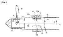
以下では、本発明の実施形態に係る可変ピッチプロペラの作動について説明する。図6は、本実施形態のブレードが最上端に位置する場合の動作状態図であり、図7は本実施形態のブレードが最下端に位置する場合の動作状態図である。 Below, the action | operation of the variable pitch propeller which concerns on embodiment of this invention is demonstrated. FIG. 6 is an operation state diagram when the blade of the present embodiment is located at the uppermost end, and FIG. 7 is an operation state diagram when the blade of the present embodiment is located at the lowermost end.
まず、プロペラ軸20が回転すると、ガイドスロット64を介して外部に突出されたガイドピン62は、スターンボス11の方に固定されたガイドリング61の内周面に形成されたピッチ決め溝63に沿ってスライド移動しながらブレード作動軸50を軸方向xに沿って前後に移動させ、ブレード作動軸50はブレード31の下端部に連結された偏心突起35を押したり引いたりすることでブレード31のピッチ角を変更する。 First, when the
ガイドピン62が、図6に示すように、ピッチ決め溝63の第1位置63aにある場合には、ブレード31はプロペラ軸20の最上端21に位置することになり、最上端21に位置するブレード31は最も小さいピッチ角を有する。その後、プロペラ軸20が回転されると、ガイドピン62はピッチ決め溝63に沿って移動しながら漸進的にブレード作動軸50を後進させ、ブレード作動軸50は偏心突起35を連続的に引くことによりプロペラ軸20の回転方向によって漸進的にブレード31のピッチ角を増加させる。 As shown in FIG. 6, when the
そして、図7に示すように、ガイドピン62がピッチ決め溝63の第2位置63bに位置するようになると、プロペラ軸20の最下端22に位置したブレード31は最大のピッチ角を有することになり、続いて、プロペラ軸20が回転するようになると、ブレード31のピッチ角は漸進的に小さくなって図6の状態に帰ることになる。 As shown in FIG. 7, when the
すなわち、ブレード31のピッチ角は、プロペラ軸20の1回転周期と同一周期でプロペラ軸20の回転角度によりブレード31の方に流入される流体の流速に対応して連続的に増加及び減少することになる。 That is, the pitch angle of the
このような構成から、油圧によりブレードのピッチ角を連続的に変更する場合には流体力とブレードのトークとが相互作用して現われるブレードの揚力と抵抗が安定(steady)しないので、ブレードのピッチ角は一定に制御されなく、引き続き不規則に変化する可能性があるが、本実施形態は機構的な構成により連続的にブレードのピッチ角を変更することができてプロペラ軸の回転角度に対応するブレードのピッチ角を安定的に可変させることができる。また、ブレードのピッチ角を変更するための別途の油圧制御のためのシステムが要らないので、プロペラボス内部及び軸系の構造が簡単になると共に重量が減少される。 From this configuration, when the pitch angle of the blade is continuously changed by hydraulic pressure, the lift force and resistance of the blade appearing due to the interaction between the fluid force and the blade talk are not stable. Although the angle is not controlled constantly and may change irregularly continuously, this embodiment can change the pitch angle of the blade continuously by the mechanical configuration, and corresponds to the rotation angle of the propeller shaft The pitch angle of the blade to be changed can be varied stably. Further, since a separate hydraulic control system for changing the pitch angle of the blade is not required, the structure of the propeller boss and the shaft system are simplified and the weight is reduced.
また、プロペラの方に流入された流速に対応して最適のブレードピッチ角を調節するので、これによるプロペラの推進効率が向上される。 In addition, since the optimum blade pitch angle is adjusted in accordance with the flow velocity flowing into the propeller, the propulsion efficiency of the propeller is improved.
以下では、本発明の他の実施形態に係る可変ピッチプロペラの駆動装置について説明する。以下では、同一機能を有する構成要素に対しては同一図面番号を付与し、詳細な説明は省略する。 Hereinafter, a variable pitch propeller driving apparatus according to another embodiment of the present invention will be described. Below, the same drawing number is given to the component which has the same function, and detailed description is abbreviate | omitted.
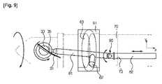
図8は、本発明の他の実施形態に係る可変ピッチプロペラの駆動装置を示す分解斜視図であり、図9は、図8の動作状態図である。 FIG. 8 is an exploded perspective view showing a variable pitch propeller driving device according to another embodiment of the present invention, and FIG. 9 is an operation state diagram of FIG.
図8に示す可変ピッチプロペラの駆動装置は、ブレード31の偏心突起35と連結されるブレード作動軸80の構造だけが相違し、上述の可変ピッチプロペラの駆動装置と同一な構成要素を有する。 The variable pitch propeller driving device shown in FIG. 8 differs from the variable pitch propeller driving device described above only in the structure of the blade operating shaft 80 connected to the
ブレード作動軸80は、偏心突起35を押したり引いたりすることができるように偏心突起35と連結され、ガイドピン62が形成された第1部分81と、ガイドプレート70の貫通孔73に挿入されてスライド可能に支持される第2部分82とを備え、第1部分81と第2部分82は回転ジョイント90を介して互いに回転可能に結合されることができる。 The blade operating shaft 80 is connected to the
回転ジョイント90は、ブレード作動軸80が軸方向xに沿って直線往復移動する場合、軸方向xに垂直である半径方向yの位置変化を吸収する機能を行う。一方、本実施形態の回転ジョイント90は、ヒンジピン91で互いに結合する構造を有するように形成されたが、これは一例に過ぎず、ブレード31のピッチ変化による半径方向yの位置変化を吸収できるように、回転される構造(ボールタイプなど)であれば、いかなる形態でも適用される。 The rotary joint 90 performs a function of absorbing a position change in the radial direction y perpendicular to the axial direction x when the blade operating shaft 80 reciprocates linearly along the axial direction x. On the other hand, the rotary joint 90 of the present embodiment is formed so as to have a structure in which the hinge pins 91 are coupled to each other. In addition, any form is applicable as long as the structure is rotated (such as a ball type).
一方、第2部分82が挿入されてスライド移動する貫通孔73は、テーパ状をなす代わりに安定的に直線移動が誘導できるように貫通孔73の直径は一定に維持される。 On the other hand, the diameter of the through-
このような構造から、ブレード作動軸80が軸方向xに沿って直線往復移動する場合、図9に示すように、ブレード作動軸80の第2部分82は、貫通孔73に挿入された状態で安定的に直線移動を行うことができ、ブレード作動軸80の第1部分81は軸方向xに沿って移動すると共に回転ジョイント90によって回転しながらブレード31のピッチ変化によるブレード作動軸80の半径方向yの位置変化の自由度を確保することができる。 With this structure, when the blade operating shaft 80 reciprocates linearly along the axial direction x, the second portion 82 of the blade operating shaft 80 is inserted into the through
以上では、特定の実施形態を参照して説明した。しかし、上記の実施形態だけに限定されず、発明が属する技術分野で通常の知識を有する者であれば、以下の請求範囲に記載した発明の技術的思想の要旨を逸脱することなく、いくらでも多様に変更実施することができる。 The above has been described with reference to specific embodiments. However, the present invention is not limited only to the above-described embodiment, and any person having ordinary knowledge in the technical field to which the invention belongs can be variously modified without departing from the spirit of the technical idea of the invention described in the following claims. Can be changed to.
Claims (14)
Translated fromJapanese前記ピッチ調節装置は、
前記ブレードの下端部に連結された偏心突起と連結され、前記偏心突起を押したり引いたりすることができるように、前記プロペラ軸の内側で直線往復移動可能に配置されるブレード作動軸と、
前記プロペラ軸の回転運動を前記ブレード作動軸の直線往復運動に変換する動力変換部と、を含み、
前記プロペラ軸内には、前記ブレード作動軸の安定的な移動のために前記ブレード作動軸が貫通してスライド可能に支持されるガイドプレートが設けられることを特徴とする可変ピッチプロペラの駆動装置。In a variable pitch propeller driving device having a blade whose pitch angle is changed along the rotation direction of the propeller shaft and a pitch adjusting device for adjusting the pitch angle,
The pitch adjusting device includes:
A blade operating shaft that is connected to an eccentric protrusion connected to a lower end of the blade and is arranged to be able to reciprocate linearly inside the propeller shaft so that the eccentric protrusion can be pushed or pulled;
Seen including and a power converter for converting the linear reciprocating motion of the blade actuating shaft a rotational movement of the propellershaft,
A drive unit for a variable pitch propeller, characterizedin thata guide plate is provided in the propeller shaft so as to be slidably supported through the blade operating shaft for stable movement of the blade operating shaft .
前記ブレード作動軸から延長され、前記プロペラ軸の外面に形成されたガイドスロットを介して突出されるガイドピンと、
前記プロペラ軸の外側縁を囲み、内面に前記ガイドピンがスライド移動するピッチ決め溝が設けられたガイドリングと、を含むことを特徴とする請求項1に記載の可変ピッチプロペラの駆動装置。The power converter is
A guide pin extending from the blade operating shaft and protruding through a guide slot formed on the outer surface of the propeller shaft;
2. The variable pitch propeller driving device according to claim 1, further comprising a guide ring that surrounds an outer edge of the propeller shaft and has a pitch-determining groove in which an inner surface slides the guide pin.
前記ガイドピンは、前記プロペラ軸と共に、回転しながら前記ピッチ決め溝に沿ってスライド移動するにより前記ガイドスロットで前後に移動することを特徴とする請求項2に記載の可変ピッチプロペラの駆動装置。The guide slot is formed to extend along the axial direction of the propeller shaft,
The driving device for a variable pitch propeller according to claim 2, wherein the guide pin moves back and forth in the guide slot by sliding along the pitch determining groove while rotating together with the propeller shaft.
前記プロペラ軸の最上端に位置する前記ブレードのピッチ角は、前記プロペラ軸の最下端に位置するピッチ角よりも相対的に小さいことを特徴とする請求項6に記載の可変ピッチプロペラの駆動装置。The propeller shaft is provided to extend through the stern boss of the hull,
The variable pitch propeller driving device according to claim6 , wherein a pitch angle of the blade located at the uppermost end of the propeller shaft is relatively smaller than a pitch angle located at the lowermost end of the propeller shaft. .
前記ブレードが前記プロペラ軸の最上側に位置する際に前記ブレードの第1ピッチ角を定義する第1位置と、
前記ブレードが前記プロペラ軸の最下側に位置する際に前記ブレードの第2ピッチ角を定義する第2位置と、を備え、
前記第1ピッチ角は最小ピッチ角を形成し、前記第2ピッチ角は最大ピッチ角を形成することを特徴とする請求項10に記載の可変ピッチプロペラの駆動装置。The pitch determining groove is
A first position defining a first pitch angle of the blade when the blade is positioned on the uppermost side of the propeller shaft;
A second position that defines a second pitch angle of the blade when the blade is positioned on the lowest side of the propeller shaft;
11. The variable pitch propeller driving apparatus according to claim10 , wherein the first pitch angle forms a minimum pitch angle, and the second pitch angle forms a maximum pitch angle.
前記第1部分と前記第2部分は、回転ジョイントを介して互いに連結されることを特徴とする請求項1に記載の可変ピッチプロペラの駆動装置。The blade operating shaft includes a first portion connected to the eccentric protrusion, and a second portion supported by the guide plate,
2. The variable pitch propeller driving apparatus according to claim1 , wherein the first portion and the second portion are connected to each other via a rotary joint.
前記ブレードの方に流入される流体の流入流速を判断して最小流入流速の地点での前記ブレードの第1ピッチ角と最大流入流速の地点での前記ブレードの第2ピッチ角とを決定し、
前記ブレードのピッチ角は、前記プロペラ軸の回転方向に沿って前記第1ピッチ角と前記第2ピッチ角との間で漸進的に大きくなったり小さくなったりすることができるように制御されることを特徴とする可変ピッチプロペラのピッチ角制御方法。
Used to drive device for a variable pitch propeller according to claim 1, inthe variable pitch pitchangle control method of a propeller for generating a propulsive force is coupled tothe propeller shaft,
Determining a second pitch angle of the blade at the point of first pitch angle and the maximum inflow velocity of the blade at the point of minimum inlet flow rate to determine the inflow velocity of the fluid flowing towardsthe blade,
The pitch angle of the blade is controlled so as to be gradually increased or decreased between the first pitch angle and the second pitch angle along the rotation direction of the propeller shaft. A pitch angle control method for a variable pitch propeller.
Applications Claiming Priority (3)
| Application Number | Priority Date | Filing Date | Title |
|---|---|---|---|
| KR10-2012-0009755 | 2012-01-31 | ||
| KR1020120009755AKR101358119B1 (en) | 2012-01-31 | 2012-01-31 | Driving apparatus of variable pitch propeller and blade pitch angle control method and the ship having the same |
| PCT/KR2012/011597WO2013115487A1 (en) | 2012-01-31 | 2012-12-27 | Variable-pitch-propeller drive device and pitch-angle control method, and boat having same |
Publications (2)
| Publication Number | Publication Date |
|---|---|
| JP2015505525A JP2015505525A (en) | 2015-02-23 |
| JP5836559B2true JP5836559B2 (en) | 2015-12-24 |
Family
ID=48905484
Family Applications (1)
| Application Number | Title | Priority Date | Filing Date |
|---|---|---|---|
| JP2014555476AActiveJP5836559B2 (en) | 2012-01-31 | 2012-12-27 | Variable pitch propeller drive device, pitch angle control method, and ship having the same |
Country Status (6)
| Country | Link |
|---|---|
| US (1) | US9694886B2 (en) |
| EP (1) | EP2810868B1 (en) |
| JP (1) | JP5836559B2 (en) |
| KR (1) | KR101358119B1 (en) |
| CN (1) | CN104245501B (en) |
| WO (1) | WO2013115487A1 (en) |
Cited By (9)
| Publication number | Priority date | Publication date | Assignee | Title |
|---|---|---|---|---|
| US10292801B2 (en) | 2012-03-29 | 2019-05-21 | Neotract, Inc. | System for delivering anchors for treating incontinence |
| US10299780B2 (en) | 2005-05-20 | 2019-05-28 | Neotract, Inc. | Apparatus and method for manipulating or retracting tissue and anatomical structure |
| US10492792B2 (en) | 2005-05-20 | 2019-12-03 | Neotract, Inc. | Devices, systems and methods for treating benign prostatic hyperplasia and other conditions |
| US10575844B2 (en) | 2005-05-20 | 2020-03-03 | Neotract, Inc. | Devices, systems and methods for treating benign prostatic hyperplasia and other conditions |
| US10912637B2 (en) | 2013-03-14 | 2021-02-09 | Neotract, Inc. | Devices, systems and methods for treating benign prostatic hyperplasia and other conditions |
| US10925587B2 (en) | 2005-05-20 | 2021-02-23 | Neotract, Inc. | Anchor delivery system |
| US11331093B2 (en) | 2012-06-29 | 2022-05-17 | Teleflex Life Sciences Limited | Flexible system for delivering an anchor |
| US11504149B2 (en) | 2005-05-20 | 2022-11-22 | Teleflex Life Sciences Limited | Median lobe destruction apparatus and method |
| US11672520B2 (en) | 2017-12-23 | 2023-06-13 | Teleflex Life Sciences Limited | Expandable tissue engagement apparatus and method |
Families Citing this family (21)
| Publication number | Priority date | Publication date | Assignee | Title |
|---|---|---|---|---|
| CN105035291A (en)* | 2015-07-24 | 2015-11-11 | 苏州金业船用机械厂 | Adjustable screw pitch propeller low in weight and long in service life |
| CN105416546A (en)* | 2015-11-25 | 2016-03-23 | 镇江同舟螺旋桨有限公司 | Propeller propelling plant with controllable pitch |
| KR102320813B1 (en)* | 2017-05-04 | 2021-11-02 | 삼성전자주식회사 | Unmanned aerial vehicle |
| CN107310703B (en)* | 2017-06-29 | 2018-10-09 | 大连碧蓝节能环保科技有限公司 | A kind of displacement marine propeller |
| CN108372921A (en)* | 2018-02-28 | 2018-08-07 | 盛海 | A kind of environmentally friendly operation ship of water conservancy |
| CN108408014A (en)* | 2018-02-28 | 2018-08-17 | 赵继兵 | A kind of environmentally friendly operation ship of the water conservancy with deinsectization function |
| CN108313246A (en)* | 2018-02-28 | 2018-07-24 | 张斌 | A kind of implement of the water conservancy with lighting device |
| CN108327878A (en)* | 2018-02-28 | 2018-07-27 | 任小依 | A kind of water conservancy implement |
| CN108327877A (en)* | 2018-02-28 | 2018-07-27 | 凌栋 | A kind of water conservancy antirust environmental protection operation ship |
| CN108327881A (en)* | 2018-02-28 | 2018-07-27 | 冯华明 | A kind of water conservancy environment protection multifunctional implement |
| CN108327879A (en)* | 2018-02-28 | 2018-07-27 | 吴顺卫 | A kind of water conservancy environment-friendly type implement |
| CN108394541A (en)* | 2018-02-28 | 2018-08-14 | 顾荣祥 | A kind of solar powered environmentally friendly operation ship of water conservancy |
| CN109278964B (en)* | 2018-09-19 | 2020-07-28 | 金立新 | Flat pitch control paddle |
| IT201800010465A1 (en)* | 2018-11-20 | 2020-05-20 | William Edoardo Scacchi | PROPELLER FOR SAILING BOATS WITH VARIABLE PITCH WITH AUTOMATIC RETURN TO FLAG POSITION WITHOUT GEARS |
| CN110155284B (en)* | 2019-06-27 | 2021-08-17 | 重庆奥普提科技有限公司 | Ocean remote sensing detection device |
| JP2021037828A (en)* | 2019-09-03 | 2021-03-11 | 三菱重工業株式会社 | Variable pitch propeller |
| NL2028224B1 (en)* | 2021-05-17 | 2022-12-02 | Ship Motion Group B V | Pitch Control Unit for a Controllable Pitch Propeller |
| CN113636053B (en)* | 2021-09-03 | 2025-04-29 | 中国矿业大学 | A coaxial differential rotating cam orthogonal gear type variable pitch propeller and control method |
| CN114475115B (en)* | 2021-12-30 | 2024-05-17 | 广州小鹏智慧充电科技有限公司 | Drive system and vehicle |
| CN119370302B (en)* | 2025-01-02 | 2025-03-25 | 天津水动力科技有限公司 | An adaptive propeller adjustment structure for a tail-mounted underwater thruster |
| CN119659954B (en)* | 2025-02-21 | 2025-06-20 | 中国科学院空天信息创新研究院 | Parachute cabin separating device |
Family Cites Families (24)
| Publication number | Priority date | Publication date | Assignee | Title |
|---|---|---|---|---|
| US675563A (en)* | 1900-10-19 | 1901-06-04 | Kirk Gardner Johnston | Propeller. |
| US2382072A (en)* | 1941-12-22 | 1945-08-14 | Lea Percy Ray | Automatic propeller pitch control device |
| US2593290A (en)* | 1950-12-20 | 1952-04-15 | Gansert Herman | Variable pitch propeller |
| US2969118A (en)* | 1957-08-21 | 1961-01-24 | United Aircraft Corp | Motor utilizing combined action of splines and cams |
| US3295610A (en)* | 1965-10-24 | 1967-01-03 | Frias Robert | Automatic propeller pitch control and adaptor |
| US3310118A (en)* | 1966-07-13 | 1967-03-21 | Franklin K Smith | Controllable pitch boat propeller |
| US3853427A (en)* | 1972-06-26 | 1974-12-10 | F Holt | Manually controlled variable pitch propeller |
| JPS5474497U (en) | 1977-11-05 | 1979-05-26 | ||
| JPS5528610A (en) | 1978-08-21 | 1980-02-29 | Toshiba Corp | Video and audio recording and reproducing unit |
| CH660863A5 (en)* | 1983-01-17 | 1987-05-29 | Escher Wyss Gmbh | ADJUSTING PROPELLER FOR SHIP DRIVE. |
| JPS6243394A (en)* | 1985-08-21 | 1987-02-25 | Ishikawajima Harima Heavy Ind Co Ltd | Screw propeller |
| JPH07477B2 (en)* | 1985-08-21 | 1995-01-11 | 石川島播磨重工業株式会社 | Wave power fin propulsion device |
| US5129785A (en)* | 1988-07-07 | 1992-07-14 | Nautical Development, Inc. | Automatic variable discrete pitch marine propeller |
| US5028210A (en) | 1990-01-05 | 1991-07-02 | The United States Of America As Represented By The Secretary Of The Navy | Propeller unit with controlled cyclic and collective blade pitch |
| IT1243015B (en)* | 1990-09-19 | 1994-05-23 | Santa Caterina Di Brena Ada & | ADJUSTABLE AND FOLDABLE BLADE PROPELLER |
| NL9201889A (en) | 1992-10-29 | 1994-05-16 | Klaas Langenberg | Adjustable screw. |
| EP1888400A1 (en)* | 2005-06-09 | 2008-02-20 | Aimbridge Pty. Ltd. | Propeller for a marine propulsion system |
| KR100836637B1 (en)* | 2007-03-29 | 2008-06-10 | 주식회사 디.에스.케이 | Variable Pitch Propeller Hydraulic Splitter (OD) Box |
| JP5273512B2 (en) | 2007-10-25 | 2013-08-28 | 株式会社Sumco | Quartz glass crucible and its manufacturing method and application |
| CN102224069B (en)* | 2008-09-22 | 2014-06-25 | 伯格推进技术公司 | An adjustable propeller arrangement and a method of distributing fluid to and/or from such an adjustable propeller arrangement |
| US8465257B1 (en)* | 2008-10-31 | 2013-06-18 | Brp Us Inc. | Variable pitch propeller |
| US8951018B1 (en)* | 2010-01-29 | 2015-02-10 | Brp Us Inc. | Variable pitch propeller and associated propeller blade |
| KR101225683B1 (en)* | 2010-06-28 | 2013-01-23 | 삼성중공업 주식회사 | propeller for ship and method to adjust pitch of propeller |
| KR101302987B1 (en) | 2010-09-10 | 2013-09-03 | 삼성중공업 주식회사 | Variable pitch marine propeller |
- 2012
- 2012-01-31KRKR1020120009755Apatent/KR101358119B1/enactiveActive
- 2012-12-27CNCN201280068586.4Apatent/CN104245501B/enactiveActive
- 2012-12-27USUS14/375,694patent/US9694886B2/enactiveActive
- 2012-12-27WOPCT/KR2012/011597patent/WO2013115487A1/enactiveApplication Filing
- 2012-12-27JPJP2014555476Apatent/JP5836559B2/enactiveActive
- 2012-12-27EPEP12867702.8Apatent/EP2810868B1/enactiveActive
Cited By (15)
| Publication number | Priority date | Publication date | Assignee | Title |
|---|---|---|---|---|
| US11090036B2 (en) | 2005-05-20 | 2021-08-17 | Neotract, Inc. | Devices, systems and methods for treating benign prostatic hyperplasia and other conditions |
| US10492792B2 (en) | 2005-05-20 | 2019-12-03 | Neotract, Inc. | Devices, systems and methods for treating benign prostatic hyperplasia and other conditions |
| US10575844B2 (en) | 2005-05-20 | 2020-03-03 | Neotract, Inc. | Devices, systems and methods for treating benign prostatic hyperplasia and other conditions |
| US11471148B2 (en) | 2005-05-20 | 2022-10-18 | Teleflex Life Sciences Limited | Devices, systems and methods for treating benign prostatic hyperplasia and other conditions |
| US10925587B2 (en) | 2005-05-20 | 2021-02-23 | Neotract, Inc. | Anchor delivery system |
| US10299780B2 (en) | 2005-05-20 | 2019-05-28 | Neotract, Inc. | Apparatus and method for manipulating or retracting tissue and anatomical structure |
| US12201283B2 (en) | 2005-05-20 | 2025-01-21 | Teleflex Life Sciences Llc | Devices, systems and methods for treating benign prostatic hyperplasia and other conditions |
| US11504149B2 (en) | 2005-05-20 | 2022-11-22 | Teleflex Life Sciences Limited | Median lobe destruction apparatus and method |
| US10292801B2 (en) | 2012-03-29 | 2019-05-21 | Neotract, Inc. | System for delivering anchors for treating incontinence |
| US11331093B2 (en) | 2012-06-29 | 2022-05-17 | Teleflex Life Sciences Limited | Flexible system for delivering an anchor |
| US10912637B2 (en) | 2013-03-14 | 2021-02-09 | Neotract, Inc. | Devices, systems and methods for treating benign prostatic hyperplasia and other conditions |
| US11850140B2 (en) | 2013-03-14 | 2023-12-26 | Teleflex Life Sciences Limited | Devices, systems and methods for treating benign prostatic hyperplasia and other conditions |
| US12042372B2 (en) | 2013-03-14 | 2024-07-23 | Teleflex Life Sciences Llc | Devices, systems and methods for treating benign prostatic hyperplasia and other conditions |
| US12121228B2 (en) | 2017-12-23 | 2024-10-22 | Teleflex Life Sciences Llc | Expandable tissue engagement apparatus and method |
| US11672520B2 (en) | 2017-12-23 | 2023-06-13 | Teleflex Life Sciences Limited | Expandable tissue engagement apparatus and method |
Also Published As
| Publication number | Publication date |
|---|---|
| US9694886B2 (en) | 2017-07-04 |
| KR101358119B1 (en) | 2014-02-07 |
| EP2810868A1 (en) | 2014-12-10 |
| EP2810868A4 (en) | 2015-12-16 |
| CN104245501B (en) | 2017-03-08 |
| US20150166157A1 (en) | 2015-06-18 |
| CN104245501A (en) | 2014-12-24 |
| EP2810868B1 (en) | 2017-03-29 |
| WO2013115487A1 (en) | 2013-08-08 |
| JP2015505525A (en) | 2015-02-23 |
| KR20130088491A (en) | 2013-08-08 |
Similar Documents
| Publication | Publication Date | Title |
|---|---|---|
| JP5836559B2 (en) | Variable pitch propeller drive device, pitch angle control method, and ship having the same | |
| US11448232B2 (en) | Propeller blade | |
| CN105398558B (en) | Variable duct screw | |
| CA2822306A1 (en) | Co-axial rotors in a wind turbine and a method of generating energy therefrom | |
| CN108438209B (en) | Cycloidal propeller eccentric circle control mechanism | |
| CN107554734B (en) | A kind of asymmetric catheter propeller that aerofoil profile is controllable | |
| CN113086149B (en) | Multi-link mechanism based on VSP cycloidal propeller | |
| RU2482010C2 (en) | Method of producing flapping motion and flapping screw to this end | |
| KR20110038146A (en) | Turbo Gear with Blade Wheels | |
| US9217332B2 (en) | Uni-directional axial turbine blade assembly | |
| CN107640306B (en) | Marine propulsion device, ship and running control method thereof | |
| CN208036590U (en) | Vertical axis propeller eccentric circle control mechanism | |
| US9051049B2 (en) | Ornithopter aircraft transmission | |
| CN212448012U (en) | Blade control assembly structure | |
| KR101185408B1 (en) | Tunnel thruster | |
| JP2007085327A (en) | Magnus type wind power generator | |
| JP2005188456A (en) | Variable pitch propeller device | |
| JP6560511B2 (en) | Horizontal axis rotor | |
| JP6978426B2 (en) | Fluid rotor with directional vanes with improved vane control | |
| JP2600070B2 (en) | Variable pitch propeller that can adjust thrust in three dimensions | |
| KR20120055319A (en) | Tunnel thruster | |
| KR102095421B1 (en) | Azimuth thruster | |
| CN217805206U (en) | Propeller and overwater equipment | |
| KR101225683B1 (en) | propeller for ship and method to adjust pitch of propeller | |
| RU2359862C2 (en) | Rotor mast |
Legal Events
| Date | Code | Title | Description |
|---|---|---|---|
| A621 | Written request for application examination | Free format text:JAPANESE INTERMEDIATE CODE: A621 Effective date:20140730 | |
| A977 | Report on retrieval | Free format text:JAPANESE INTERMEDIATE CODE: A971007 Effective date:20150528 | |
| A131 | Notification of reasons for refusal | Free format text:JAPANESE INTERMEDIATE CODE: A131 Effective date:20150602 | |
| A521 | Request for written amendment filed | Free format text:JAPANESE INTERMEDIATE CODE: A523 Effective date:20150831 | |
| TRDD | Decision of grant or rejection written | ||
| A01 | Written decision to grant a patent or to grant a registration (utility model) | Free format text:JAPANESE INTERMEDIATE CODE: A01 Effective date:20151027 | |
| A61 | First payment of annual fees (during grant procedure) | Free format text:JAPANESE INTERMEDIATE CODE: A61 Effective date:20151103 | |
| R150 | Certificate of patent or registration of utility model | Ref document number:5836559 Country of ref document:JP Free format text:JAPANESE INTERMEDIATE CODE: R150 | |
| R250 | Receipt of annual fees | Free format text:JAPANESE INTERMEDIATE CODE: R250 | |
| R250 | Receipt of annual fees | Free format text:JAPANESE INTERMEDIATE CODE: R250 | |
| R250 | Receipt of annual fees | Free format text:JAPANESE INTERMEDIATE CODE: R250 | |
| R250 | Receipt of annual fees | Free format text:JAPANESE INTERMEDIATE CODE: R250 | |
| R250 | Receipt of annual fees | Free format text:JAPANESE INTERMEDIATE CODE: R250 | |
| R250 | Receipt of annual fees | Free format text:JAPANESE INTERMEDIATE CODE: R250 | |
| R250 | Receipt of annual fees | Free format text:JAPANESE INTERMEDIATE CODE: R250 |