JP5836011B2 - X-ray CT (Computed Tomography) apparatus, radiation detector and manufacturing method thereof - Google Patents
X-ray CT (Computed Tomography) apparatus, radiation detector and manufacturing method thereofDownload PDFInfo
- Publication number
- JP5836011B2 JP5836011B2JP2011183452AJP2011183452AJP5836011B2JP 5836011 B2JP5836011 B2JP 5836011B2JP 2011183452 AJP2011183452 AJP 2011183452AJP 2011183452 AJP2011183452 AJP 2011183452AJP 5836011 B2JP5836011 B2JP 5836011B2
- Authority
- JP
- Japan
- Prior art keywords
- collimator
- ray
- modules
- module
- plate
- Prior art date
- Legal status (The legal status is an assumption and is not a legal conclusion. Google has not performed a legal analysis and makes no representation as to the accuracy of the status listed.)
- Active
Links
Images


Classifications
- A—HUMAN NECESSITIES
- A61—MEDICAL OR VETERINARY SCIENCE; HYGIENE
- A61B—DIAGNOSIS; SURGERY; IDENTIFICATION
- A61B6/00—Apparatus or devices for radiation diagnosis; Apparatus or devices for radiation diagnosis combined with radiation therapy equipment
- A61B6/02—Arrangements for diagnosis sequentially in different planes; Stereoscopic radiation diagnosis
- A61B6/03—Computed tomography [CT]
- A—HUMAN NECESSITIES
- A61—MEDICAL OR VETERINARY SCIENCE; HYGIENE
- A61B—DIAGNOSIS; SURGERY; IDENTIFICATION
- A61B6/00—Apparatus or devices for radiation diagnosis; Apparatus or devices for radiation diagnosis combined with radiation therapy equipment
- A61B6/42—Arrangements for detecting radiation specially adapted for radiation diagnosis
- A61B6/4291—Arrangements for detecting radiation specially adapted for radiation diagnosis the detector being combined with a grid or grating
- G—PHYSICS
- G21—NUCLEAR PHYSICS; NUCLEAR ENGINEERING
- G21K—TECHNIQUES FOR HANDLING PARTICLES OR IONISING RADIATION NOT OTHERWISE PROVIDED FOR; IRRADIATION DEVICES; GAMMA RAY OR X-RAY MICROSCOPES
- G21K1/00—Arrangements for handling particles or ionising radiation, e.g. focusing or moderating
- G21K1/02—Arrangements for handling particles or ionising radiation, e.g. focusing or moderating using diaphragms, collimators
- G21K1/025—Arrangements for handling particles or ionising radiation, e.g. focusing or moderating using diaphragms, collimators using multiple collimators, e.g. Bucky screens; other devices for eliminating undesired or dispersed radiation
- G—PHYSICS
- G21—NUCLEAR PHYSICS; NUCLEAR ENGINEERING
- G21K—TECHNIQUES FOR HANDLING PARTICLES OR IONISING RADIATION NOT OTHERWISE PROVIDED FOR; IRRADIATION DEVICES; GAMMA RAY OR X-RAY MICROSCOPES
- G21K2207/00—Particular details of imaging devices or methods using ionizing electromagnetic radiation such as X-rays or gamma rays
- Y—GENERAL TAGGING OF NEW TECHNOLOGICAL DEVELOPMENTS; GENERAL TAGGING OF CROSS-SECTIONAL TECHNOLOGIES SPANNING OVER SEVERAL SECTIONS OF THE IPC; TECHNICAL SUBJECTS COVERED BY FORMER USPC CROSS-REFERENCE ART COLLECTIONS [XRACs] AND DIGESTS
- Y10—TECHNICAL SUBJECTS COVERED BY FORMER USPC
- Y10T—TECHNICAL SUBJECTS COVERED BY FORMER US CLASSIFICATION
- Y10T29/00—Metal working
- Y10T29/49—Method of mechanical manufacture
- Y10T29/49826—Assembling or joining
Landscapes
- Health & Medical Sciences (AREA)
- Life Sciences & Earth Sciences (AREA)
- Engineering & Computer Science (AREA)
- Medical Informatics (AREA)
- Physics & Mathematics (AREA)
- High Energy & Nuclear Physics (AREA)
- Radiology & Medical Imaging (AREA)
- Animal Behavior & Ethology (AREA)
- Optics & Photonics (AREA)
- Pathology (AREA)
- Biophysics (AREA)
- Biomedical Technology (AREA)
- Heart & Thoracic Surgery (AREA)
- Molecular Biology (AREA)
- Surgery (AREA)
- Nuclear Medicine, Radiotherapy & Molecular Imaging (AREA)
- General Health & Medical Sciences (AREA)
- Public Health (AREA)
- Veterinary Medicine (AREA)
- Spectroscopy & Molecular Physics (AREA)
- General Engineering & Computer Science (AREA)
- Apparatus For Radiation Diagnosis (AREA)
- Measurement Of Radiation (AREA)
Description
Translated fromJapanese本発明の実施形態は、X線CT装置、放射線検出器及びその製造方法に関する。 Embodiments described herein relate generally to an X-ray CT apparatus, a radiation detector, and a manufacturing method thereof.
従来、X線CT装置などの放射線診断装置は、X線やγ線などの放射線を検出するための放射線検出器を備える。そして、放射線診断装置は、放射線検出器に入射する放射線から散乱線を除去するコリメータを備えるのが一般的である。かかるコリメータには、チャンネル方向からの散乱線を除去する1次元のコリメータと、チャンネル方向及びスライス方向(体軸方向)からの散乱線を除去する2次元のコリメータとがある。 Conventionally, a radiation diagnostic apparatus such as an X-ray CT apparatus includes a radiation detector for detecting radiation such as X-rays and γ-rays. The radiation diagnostic apparatus generally includes a collimator that removes scattered radiation from radiation incident on the radiation detector. Such collimators include a one-dimensional collimator that removes scattered rays from the channel direction and a two-dimensional collimator that removes scattered rays from the channel direction and the slice direction (body axis direction).
ここで、従来、1次元のコリメータは、全チャンネル分のコリメータを一体で切れ目なく作成することで、コリメータ板の板厚やピッチが均一になるように製造される。一方、2次元のコリメータは、2次元の方向にコリメータ板を配置する必要があるため、全チャンネル分及び全スライス分のコリメータを一体で切れ目なく作成することが難しい。そのため、2次元のコリメータについては、複数のコリメータモジュールを作成し、各コリメータをチャンネル方向及びスライス方向に並べて配置する製造方法が用いられている。 Here, conventionally, a one-dimensional collimator is manufactured so that the thickness and pitch of the collimator plates are uniform by integrally creating collimators for all the channels. On the other hand, since a two-dimensional collimator needs to dispose a collimator plate in a two-dimensional direction, it is difficult to create collimators for all channels and all slices integrally without any breaks. Therefore, for the two-dimensional collimator, a manufacturing method is used in which a plurality of collimator modules are created and the collimators are arranged in the channel direction and the slice direction.
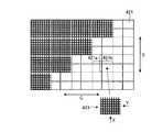
しかしながら、複数のコリメータモジュールを並べて配置する従来技術では、コリメータ板の板厚及びピッチが不均一になってしまう場合があった。図20〜23は、従来技術における課題を説明するための図である。 However, in the conventional technique in which a plurality of collimator modules are arranged side by side, the thickness and pitch of the collimator plates may become uneven. 20-23 is a figure for demonstrating the subject in a prior art.
例えば、図20に示すように、四方に外枠を有するコリメータモジュールを並べる場合には、図21に示すように、モジュールのつなぎ目でコリメータ板の板厚やピッチがチャンネル方向(矢印Cの方向)やスライス方向(矢印Sの方向)で不連続になってしまう。また、例えば、図22及び23に示すように、2方に外枠を形成したコリメータモジュールを、外枠がない側に突出するコリメータ板の端部が隣接するモジュールの外枠に当接するように並べる場合には、製造誤差によってモジュール間でピッチのずれが生じてしまうことがある。このピッチの誤差は、組み合わせるモジュールの数が増えるほど累積して大きくなってしまう。このように、従来技術では、コリメータ板の板厚及びピッチが不均一になってしまう場合があった。 For example, when collimator modules having outer frames in four directions are arranged as shown in FIG. 20, the thickness and pitch of the collimator plates at the joints of the modules are in the channel direction (direction of arrow C) as shown in FIG. Or in the slice direction (direction of arrow S). Also, for example, as shown in FIGS. 22 and 23, a collimator module having an outer frame formed in two directions so that the end of the collimator plate protruding to the side without the outer frame abuts the outer frame of the adjacent module. In the case of arranging them, a deviation in pitch may occur between modules due to manufacturing errors. The pitch error increases as the number of modules to be combined increases. As described above, in the prior art, the plate thickness and pitch of the collimator plate may be uneven.
実施形態のX線CT装置は、X線検出部と、コリメータ部とを備える。X線検出部は、被検体を透過したX線を検出する。コリメータ部は、前記X線検出部に入射するX線から散乱線を除去する。ここで、コリメータ部は、複数のコリメータモジュールと、固定部とを備える。複数のコリメータモジュールは、互いに直交するチャンネル方向及びスライス方向に沿って格子状に配置された複数のコリメータ板をそれぞれ有する。固定部は、前記支持部に設けられ、前記複数のコリメータモジュールの前記チャンネル方向及び前記スライス方向の位置を固定する。また、複数のコリメータモジュールは、それぞれ、少なくとも一つの側部に形成された外枠をさらに有し、かつ、前記複数のコリメータ板が、前記少なくとも一つの側部以外の側部の少なくとも一つから端部を突出させた状態で配置される。固定部は、前記複数のコリメータモジュールを、前記チャンネル方向及び前記スライス方向に沿って並べた状態で、かつ、各コリメータモジュールが有する前記コリメータ板の突出した端部が隣接するコリメータモジュールの外枠に接触した状態で固定する。The X-ray CT apparatus according to the embodiment includes an X-ray detection unit and a collimator unit. The X-ray detection unit detects X-rays that have passed through the subject. The collimator unit removes scattered rays from the X-rays incident on the X-ray detection unit. Here, the collimator unit includes a plurality of collimatormodules, and asolid tough. A plurality of collimator modules, each having a pluralityof co Rimeta plates arranged in a grid pattern along the channel and slice directions perpendicular to eachother. Solid tough is provided on the support unit, securing the channel direction and the slice direction positions of the plurality of collimator modules.Each of the plurality of collimator modules further includes an outer frame formed on at least one side portion, and the plurality of collimator plates are formed from at least one side portion other than the at least one side portion. It arrange | positions in the state which made the edge part protrude. The fixing unit is a state in which the plurality of collimator modules are arranged along the channel direction and the slice direction, and the protruding end of the collimator plate included in each collimator module is on the outer frame of the adjacent collimator module. Fix in contact.
(第1の実施形態)
まず、第1の実施形態について説明する。図1は、第1の実施形態に係るX線CT装置100の構成を示す図である。図1に示すように、X線CT装置100は、ガントリ110と、高電圧発生装置120と、前処理装置130と、再構成装置140と、画像処理装置150と、記憶装置160と、入力装置170と、表示装置180と、システムコントローラ190とを有する。(First embodiment)
First, the first embodiment will be described. FIG. 1 is a diagram illustrating a configuration of an
ガントリ110は、被検体にX線を照射し、被検体を透過したX線を検出して生データを生成する。このガントリ110は、X線管111と、スリップリング112と、X線検出器200と、フレーム113と、回転部114と、データ収集回路(Data Acquisition System:DAS)115と、非接触データ伝送装置116とを有する。 The gantry 110 irradiates the subject with X-rays, detects X-rays transmitted through the subject, and generates raw data. The gantry 110 includes an
X線管111は、スリップリング112を経由して高電圧発生装置120から供給される管電圧及び管電流により、被検体に対して照射するためのX線を発生する。X線検出器200は、X線管111から発生して被検体を透過したX線を検出する。なお、このX線検出器200については、後に詳細に説明する。 The
フレーム113は、円環状に形成され、回転軸RAを中心にして回転可能に設けられている。このフレーム113は、回転軸RAを挟んで対向するようにX線管111及びX線検出器200を支持する。回転部114は、回転軸RAを中心にしてフレーム113を回転させる。例えば、回転部114は、0.4秒/回転の速度でフレーム113を高速に回転させる。 The
データ収集回路115は、X線検出器200によって検出されたX線の信号を収集し、増幅し、さらにデジタル信号のデータ(生データ)に変換する。非接触データ伝送装置116は、データ収集回路115から出力される生データを前処理装置130に送信する。 The
高電圧発生装置120は、ガントリ110のX線管111に管電圧及び管電流を供給してX線を発生させる装置である。前処理装置130は、非接触データ伝送装置116から送信される生データに対して感度補正などの補正処理を行うことによって、画像再構成のもとになる投影データを生成する。 The
再構成装置140は、前処理装置130によって生成された投影データに対して所定の再構成処理を行うことによって、被検体の画像データを再構成する。画像処理装置150は、再構成装置140により再構成された画像データを用いて3次元画像、曲面MPR(Multi Planar Reconstruction)画像、クロスカット画像などを生成する。 The reconstruction device 140 reconstructs image data of the subject by performing predetermined reconstruction processing on the projection data generated by the preprocessing device 130. The image processing apparatus 150 uses the image data reconstructed by the reconstruction apparatus 140 to generate a three-dimensional image, a curved MPR (Multi Planar Reconstruction) image, a crosscut image, and the like.
記憶装置160は、前処理装置130によって生成された投影データや、再構成装置140によって再構成された画像データ、画像処理装置150によって生成された各種画像などを記憶する。例えば、記憶装置160は、HDD(Hard Disk Drive)やDVD(Digital Versatile Disc)ドライブなどである。 The
入力装置170は、X線CT装置100に対する各種操作を操作者から受け付ける。例えば、入力装置170は、キーボードやマウスなどである。表示装置180は、再構成装置140又は画像処理装置150により生成された各種画像や、操作者から各種操作を受け付けるためのGUI(Graphical User Interface)などを出力する。例えば、表示装置180は、液晶パネルやCRT(Cathode Ray Tube)モニタなどである。 The input device 170 receives various operations on the
システムコントローラ190は、入力装置170によって受け付けられた各種操作に基づいて、X線CT装置100全体の動作を制御する。 The
次に、図1に示したX線検出器200の構成について説明する。図2は、図1に示したX線検出器200の構成を示す図である。図2に示すように、X線検出器200は、X線検出部210と、コリメータ部220とを有する。なお、図2において、矢印Cは、チャンネル方向を示している。また、矢印Sは、チャンネル方向に直交するスライス方向(体軸方向)を示している。 Next, the configuration of the
X線検出部210は、X線管111により発生して被検体を透過したX線を検出する。具体的には、X線検出部210は、シンチレータアレイと、PD(Photo Diode)アレイと、回路基板とを有する。シンチレータアレイは、チャンネル方向及びスライス方向に配列された複数のシンチレータブロックを有し、X線を受けて蛍光を発生させる。PDアレイは、複数のフォトダイオードを有し、シンチレータアレイにより発生した蛍光を電気信号に変換する。回路基板は、PDアレイにより変換された電気信号を取り込んでデータ収集回路115に出力する。 The
コリメータ部220は、X線検出部210に入射するX線から散乱線を除去する。具体的には、コリメータ部220は、コリメータ枠部221と、コリメータ基部222と、複数のコリメータモジュール223とを有する。 The
コリメータ枠部221は、X線の入射方向に厚みを有する概略矩形状に形成され、かつ、X線管111の焦点fを中心とする球面に沿って湾曲するように形成されている。そして、コリメータ枠部221は、内側にコリメータ基部222及び複数のコリメータモジュール223を保持する。 The
コリメータ基部222は、複数のコリメータモジュール223をチャンネル方向及びスライス方向に配列させて支持する。図3は、図2に示したコリメータ基部222の外観を示す図である。図3に示すように、具体的には、コリメータ基部222は、チャンネル方向及びスライス方向に並ぶように格子状に配列された複数のコリメータ板222aを有する。このように、コリメータ板222aが格子状に配列されることで、コリメータ基部222においてマトリクス状に複数の区画が形成される。これら複数の区画それぞれには、後述するコリメータモジュール223が収納される。 The
また、図3に示すように、複数のコリメータ板222aそれぞれは、円弧状に形成されており、X線管111の焦点fに円弧の中心が一致するように配置されている。これにより、コリメータ基部222全体が、焦点fを中心とする球面に沿って湾曲する形状となる。このため、各コリメータ板222aによって区分けされた区画それぞれにコリメータモジュール223が配置された際に、各コリメータモジュール223がそれぞれ焦点fに向くようになる。 As shown in FIG. 3, each of the plurality of
コリメータモジュール223は、コリメータ基部222が有する複数のコリメータ板222aによって区切られた複数の区画それぞれに配置され、X線検出部210に入射するX線から散乱線を除去する。図4〜7は、図2に示したコリメータモジュール223の構成を示す図である。 The
図4に示すように、具体的には、コリメータモジュール223は、チャンネル方向及びスライス方向に並ぶように格子状に配列されたコリメータ板223aを有する。例えば、コリメータ板223aは、チャンネル方向に24列配置され、スライス方向に64列配置される。 As shown in FIG. 4, specifically, the
ここで、各コリメータモジュール223が有する複数のコリメータ板223aは、コリメータ基部222が有するコリメータ板222aと同じ厚さを有している。なお、図4では、チャンネル方向及びスライス方向それぞれに沿って複数のコリメータ板223aが平行に並ぶように図示したが、実際には、各コリメータ板223aは、それぞれX線管111の焦点fを向くように配置されている。かかるコリメータモジュール223は、小さな単位で作成されるので、製造誤差によるコリメータ板223aのピッチずれが小さい。 Here, the plurality of
また、図5に示すように、コリメータ板223aは、それぞれの両端より内側で互いに直交するように配置されている。すなわち、コリメータ板223aは、四方を取り囲む外枠がなく、複数のコリメータ板223aそれぞれの端部が四方それぞれに突出するように形成されている。 Further, as shown in FIG. 5, the
そして、図6に示すように、各コリメータ板223aは、コリメータ基部222が有するコリメータ板222aによって区分けされた区画にコリメータモジュール223が配置された際に、その区画を囲むコリメータ板222aの板面にそれぞれの両端が接するように形成されている。これにより、コリメータ基部222が有するコリメータ板222aが、コリメータモジュール223の外枠となる。また、隣接して配置されたコリメータモジュール223の間がコリメータ板223aと同じ厚さのコリメータ板222aで仕切られることになり、コリメータモジュール223のつなぎ目でもコリメータ板の厚さが連続するようになる。 As shown in FIG. 6, each
また、図6に示すように、コリメータ板222aによって区分けされた各区画にコリメータモジュール223が配置されることで、コリメータモジュール223がチャンネル方向及びスライス方向に沿って精度よく配列される。これにより、コリメータモジュール間でピッチのずれが生じるのを防ぐことができる。 Further, as shown in FIG. 6, the
なお、各コリメータ板223aの端部は、例えば接着剤などを用いて、コリメータ基部222のコリメータ板222aの板面にそれぞれ固定される。このとき、例えば、図7の上側に示すように、複数のコリメータ板223aの端部を1枚おきに固定されてもよいし、図7の下側に示すように、複数のコリメータ板223aのうちいずれか1枚の端部が固定されてもよい。 In addition, the edge part of each
上述したように、第1の実施形態に係るX線CT装置100は、被検体を透過したX線を検出するX線検出部210と、X線検出部210に入射するX線から散乱線を除去するコリメータ部220とを備える。ここで、コリメータ部220は、互いに直交するチャンネル方向及びスライス方向に並ぶように格子状に配列された複数のコリメータ板222aを有するコリメータ基部222と、複数のコリメータ板222aによって区切られた複数の区画それぞれに配置され、チャンネル方向及びスライス方向に並ぶように格子状に配列された複数のコリメータ板223aを有する複数のコリメータモジュール223とを備える。そして、各コリメータモジュール223が有する複数のコリメータ板223aは、コリメータ基部222が有するコリメータ板222aと同じ厚さを有し、それぞれの両端より内側で互いに直交するように配置され、当該コリメータモジュール223が区画に配置された際にその区画を囲むコリメータ板222aの板面にそれぞれの両端が接するように形成されている。 As described above, the
すなわち、コリメータ基部222が有するコリメータ板222aと各コリメータモジュール223が有するコリメータ板223aとは、それぞれ同じ厚さを有するので、コリメータ部220全体として、コリメータ板の厚さが均一になる。また、コリメータ基部222を基準にして、複数のコリメータモジュール223がチャンネル方向及びスライス方向に精度よく配列されるので、コリメータ部220全体として、コリメータ板のピッチが均一になる。したがって、第1の実施形態によれば、コリメータ板の板厚及びピッチが均一なコリメータを得ることができる。また、散乱線の除去量がチャンネル間及びスライス間で均一になるので、アーチファクトが少ない画像が得られる。 That is, since the
また、第1の実施形態では、コリメータ基部222が有する複数のコリメータ板222aそれぞれは、円弧状に形成されており、X線を発生するX線管111の焦点fに円弧の中心が一致するように配置されている。したがって、第1の実施形態によれば、各コリメータ板222aによって区分けされた区画それぞれにコリメータモジュール223が配置された際に、各コリメータモジュール223がそれぞれ焦点fに向くようになる。すなわち、2次元のコリメータモジュールを焦点fに向けて精度よく配列することができる。 Further, in the first embodiment, each of the plurality of
(第2の実施形態)
次に、第2の実施形態について説明する。本実施形態では、第1の実施形態で説明したコリメータモジュール223の固定方法の一例について説明する。図8は、第2の実施形態に係るコリメータモジュール223の固定方法を示す図である。(Second Embodiment)
Next, a second embodiment will be described. In the present embodiment, an example of a method for fixing the
図8に示すように、本実施形態では、コリメータ基部222が有するコリメータ板222aの板面には、X線の入射方向に沿って複数の溝222bが形成される。そして、コリメータ板222aによって区分けされた区画にコリメータモジュール223が配置された際に、コリメータモジュール223が有するコリメータ板223aの端部が溝222bに当接する。ここで、コリメータ板222aに形成された溝222bにコリメータ板223aの端部が当接することで、コリメータ板222aによって区分けされた区画においてコリメータモジュール223が位置決めされる。 As shown in FIG. 8, in this embodiment, a plurality of
なお、溝222bは、コリメータモジュール223が有するコリメータ板223aの枚数と同じ数だけ形成されてもよいし、コリメータ板223aの枚数より少ない数だけ形成されてもよい。すなわち、少なくとも一つの溝222bが形成されていればよい。また、コリメータモジュール223が配置される区画を囲む4つの板面全ての板面に溝222bが形成されていてもよいし、一つの板面、2つの板面、又は3つの板面に溝222bが形成されていてもよい。 The
このように、第2の実施形態によれば、コリメータ基部222が有するコリメータ板222aの板面に形成された溝222bによってコリメータモジュール223の位置が決められるので、各コリメータモジュール223を精度よく固定することができる。 As described above, according to the second embodiment, the position of the
(第3の実施形態)
次に、第3の実施形態について説明する。本実施形態では、第1の実施形態で説明したコリメータモジュール223の固定方法について、第2の実施形態とは異なる他の例を説明する。図9及び10は、第3の実施形態に係るコリメータモジュール223の固定方法を示す図である。(Third embodiment)
Next, a third embodiment will be described. In the present embodiment, another example of the method for fixing the
図9に示すように、本実施形態では、コリメータ板222aによって区分けされた区画にコリメータモジュール223が配置された際に、コリメータ板223aの端部がコリメータ板222aの一部に係合する(図9に示す円A内を参照)。 As shown in FIG. 9, in this embodiment, when the
具体的には、本実施形態では、コリメータモジュール223が有するコリメータ板223aの端部に係合部が形成される。また、コリメータ基部222が有するコリメータ板222aには、コリメータ板223aの端部に形成された係合部に係合する被係合部が形成される。そして、コリメータ板222aによって区分けされた区画にコリメータモジュール223が配置された際に、コリメータ板222aの被係合部にコリメータ板223aの端部に形成された係合部が係合する。このように、コリメータ板223aの端部がコリメータ板222aの一部に係合することで、コリメータ板222aによって区分けされた区画においてコリメータモジュール223が位置決めされる。 Specifically, in the present embodiment, an engaging portion is formed at the end of the
例えば、図10に示すように、コリメータモジュール223が有するコリメータ板223aの端部には、切り欠き223cが係合部として形成される。また、コリメータ基部222が有するコリメータ板222aには、コリメータ板223aの切り欠き223cと噛み合うことが可能な切り欠き222cが被係合部として形成される。 For example, as shown in FIG. 10, a
なお、ここでは、係合部及び被係合部が切り欠きである場合について説明したが、係合部及び被係合部の形状はこれに限られない。例えば、コリメータモジュール223の端部に凸部が形成され、コリメータ基部222が有するコリメータ板222aの板面に、コリメータモジュール223の凸部に嵌合する穴が形成されてもよい。 In addition, although the case where the engaging part and the engaged part are notches has been described here, the shapes of the engaging part and the engaged part are not limited thereto. For example, a convex portion may be formed at the end of the
また、係合部及び被係合部は、コリメータモジュール223が有する全てのコリメータ板223aの端部について形成されてもよいし、一部の端部について形成されてもよい。すなわち、複数のコリメータ板223aの端部のうち少なくとも一つの端部について係合部及び被係合部が形成されていればよい。 Further, the engaging portion and the engaged portion may be formed for the end portions of all the
このように、第3の実施形態によれば、コリメータモジュール223が有するコリメータ板223aの端部に形成された係合部と、コリメータ基部222が有するコリメータ板222aに形成された被係合部とが係合することによって、コリメータモジュール223の位置が決められるので、各コリメータモジュール223を精度よく固定することができる。また、コリメータ板223aの厚さが薄く、その板面に溝を形成することができないような場合でも、各コリメータモジュール223の位置決めを行うことができる。 Thus, according to the third embodiment, the engaging portion formed on the end of the
(第4の実施形態)
次に、第4の実施形態について説明する。本実施形態では、第1の実施形態で説明したX線検出部210を複数の部分に分割し、分割された各部分をそれぞれコリメータモジュール223と組み合わせてモジュール化する場合について説明する。図11は、第4の実施形態に係るX線検出部及びコリメータモジュール223を示す図である。(Fourth embodiment)
Next, a fourth embodiment will be described. In the present embodiment, a case will be described in which the
本実施形態では、X線検出部210は、コリメータモジュール223に対応する大きさに分割されている。すなわち、X線検出部210は、コリメータ基部222が有する複数のコリメータ板222aによって区切られた複数の区画ごとに、複数のブロックに分割されている。そして、分割された各ブロックが、それぞれコリメータモジュール223に取り付けられている。 In the present embodiment, the
具体的には、図11に示すように、シンチレータアレイを分割したブロック211、PDアレイを分割したブロック212、及び、回路基板を分割したブロック213をそれぞれコリメータモジュール223に取り付ける。これにより、コリメータモジュール223とX線検出部210のブロックとがモジュール化される。さらに、図11に示すように、DAS115を分割したブロック115aをコリメータモジュール223及びX線検出部210のブロックと組み合わせてモジュール化してもよい。 Specifically, as shown in FIG. 11, a
このように、第4の実施形態によれば、X線検出部210の一部、又は、X線検出部210及びDAS115の一部がコリメータモジュール223と組み合わせてモジュール化される。これにより、X線検出部210やDAS115の一部が故障した場合でも、故障箇所を含むブロックを交換することで、容易に故障から復旧させることができる。また、モジュールの数を増やしたり減らしたりすることで、X線検出器やDASの大きさを容易に変更することができるので、X線検出器やDASの開発における拡張性を高めることができる。 Thus, according to the fourth embodiment, a part of the
なお、上記第1〜第4の実施形態において、コリメータ枠部221は、チャンネル方向に沿った複数の直線上及びスライス方向に沿った複数の直線上に複数のコリメータモジュール223を並べて支持する支持部として機能する。また、コリメータ基部222は、支持部であるコリメータ枠部221に設けられ、複数のコリメータモジュール223のチャンネル方向及びスライス方向の位置を固定する固定部として機能する。 In the first to fourth embodiments, the
ここで、支持部及び固定部は、上記第1〜第4の実施形態に示したものに限られず、各種の形状のものを用いることができる。そこで、以下では、支持部及び固定部の他の例について説明する。なお、上記実施形態で説明した各部と同一の機能を有するものについては、同一の符号を付すこととして詳細な説明を省略する。 Here, a support part and a fixing | fixed part are not restricted to what was shown to the said 1st-4th embodiment, The thing of various shapes can be used. Therefore, in the following, another example of the support part and the fixing part will be described. In addition, about the thing which has the same function as each part demonstrated in the said embodiment, detailed description is abbreviate | omitted as attaching | subjecting the same code | symbol.
(第5の実施形態)
まず、第5の実施形態について説明する。本実施形態では、支持部として板状の部材を用いた場合について説明する。図12は、第5の実施形態に係るコリメータ部320を示す図である。図12に示すように、本実施形態では、コリメータ部320は、コリメータ支持板321と、複数のコリメータモジュール323とを有する。ここで、各コリメータモジュール323は、コリメータ支持板321を介して、X線検出部210の上に配置される。(Fifth embodiment)
First, a fifth embodiment will be described. This embodiment demonstrates the case where a plate-shaped member is used as a support part. FIG. 12 is a diagram showing a
コリメータ支持板321は、X線の焦点を中心とする球面に沿って湾曲する板状に形成される。そして、コリメータ支持板321は、X線が照射される側の面上に複数のコリメータモジュール323を並べて支持する。ここで、コリメータ支持板321は、チャンネル方向(矢印Cの方向)に沿った複数の直線上、及び、スライス方向(矢印Sの方向)に沿った複数の直線上に、複数のコリメータモジュールを並べて支持する。なお、コリメータ支持板321は、例えばガラスエポキシのように、X線の吸収係数が低い材質で形成される。 The
コリメータモジュール323は、X線検出部210に入射するX線から散乱線を除去する。図13〜15は、第5の実施形態に係るコリメータ支持板321及びコリメータモジュール323の構成を示す図である。ここで、図13は、コリメータ支持板321及びコリメータモジュール323の上面図である。また、図14は、図13に示す矢印Aの方向からみたコリメータモジュール323の側面図であり、図15は、図13に示す矢印Bの方向からみたコリメータモジュール323の側面図である。 The
図13に示すように、各コリメータモジュール323は、チャンネル方向(矢印Cの方向)に沿った等間隔に並ぶ複数の平行な直線上、及び、スライス方向(矢印Sの方向)に沿った等間隔に並ぶ複数の平行な直線上に、並べて配置される。なお、本実施形態では、コリメータモジュール323として、例えば、図13の右下に示すように、2方に外枠を形成したコリメータモジュールが用いられる。 As shown in FIG. 13, the
ここで、コリメータ支持板321において、複数のコリメータモジュール323が配置される面上には、固定部として、各コリメータモジュール323が置かれる区画(図13に点線で示された区画)ごとに、各コリメータモジュール323に設けられた被係合部に係合する係合部が形成される。本実施形態では、例えば、係合部として、コリメータ支持板321の各区画における1つの対角線上の両端部に、係合凹部321a及び321bが形成される。 Here, in the
また、図14及び15に示すように、コリメータモジュール323は、チャンネル方向及びスライス方向に並ぶように格子状に配列された複数のコリメータ板323aを有する。ここで、各コリメータモジュール323が有する各コリメータ板323aは、全て同じ厚さを有しており、それぞれX線管111の焦点fを向くように配置されている。 As shown in FIGS. 14 and 15, the
そして、コリメータモジュール323には、コリメータ支持板321に形成された係合部に係合する被係合部が形成される。本実施形態では、例えば、図14及び15に示すように、被係合部として、コリメータモジュール323の底部における1つの対角線上の両端部に係合凸部324a及び324bが設けられる。係合凸部324aは、コリメータ支持板321の区画にコリメータモジュール323が置かれた際に係合凹部321aに係合する位置に設けられる。また、係合凸部324bは、コリメータ支持板321の区画にコリメータモジュール323が置かれた際に係合凹部321bに係合する位置に設けられる。 The
そして、各コリメータモジュール323の係合凸部324a及び324bがコリメータ支持板321の各区画に形成された係合凹部321a及び321bに係合することで、各コリメータモジュール323が、チャンネル方向に沿った複数直線上及びスライス方向に沿った複数の直線上に並べられた状態で、コリメータ支持板321上に固定される。 Then, the engagement
上述したように、第5の実施形態では、支持部であるコリメータ支持板321は、X線の焦点を中心とする球面に沿って湾曲する板状に形成され、X線が照射される側の面上に複数のコリメータモジュール323を並べて支持する。また、固定部は、コリメータ支持板321において複数のコリメータモジュール323が配置される面上に設けられた複数の係合凹部321a及び321bを有し、各係合凹部が各コリメータモジュール323に設けられた係合凸部324a及び324bと係合することで複数のコリメータモジュール323の位置を固定する。したがって、第5の実施形態によれば、支持部として板状の部材を用いることによって、簡易な構成で、コリメータ板の板厚及びピッチが均一なコリメータを得ることができる。 As described above, in the fifth embodiment, the
なお、上記実施形態では、コリメータ支持板321に係合凹部が形成され、コリメータモジュール323に係合凸部が設けられる場合について説明したが、固定部の実施形態はこれに限られない。例えば、コリメータ支持板321に係合凸部が設けられ、コリメータモジュール323に係合凹部が形成されてもよい。 In addition, although the said embodiment demonstrated the case where an engagement recessed part was formed in the
(第6の実施形態)
次に、第6の実施形態について説明する。本実施形態では、第5の実施形態と同様に支持部として板状の部材を用いつつ、他の形状の固定部を用いた例について説明する。本実施形態では、コリメータ部は、コリメータ支持板421と、複数のコリメータモジュール423とを有する。ここで、各コリメータモジュール423は、コリメータ支持板421を介して、X線検出部210の上に配置される。(Sixth embodiment)
Next, a sixth embodiment will be described. In the present embodiment, an example in which a plate-shaped member is used as a support portion as in the fifth embodiment and a fixed portion having another shape is used will be described. In the present embodiment, the collimator unit includes a
コリメータ支持板421は、図12に示したコリメータ支持板321と同様に、X線の焦点を中心とする球面に沿って湾曲する板状に形成される。そして、コリメータ支持板421は、X線が照射される側の面上に複数のコリメータモジュール423を並べて支持する。ここで、コリメータ支持板421は、チャンネル方向(矢印Cの方向)に沿った複数の直線上、及び、スライス方向(矢印Sの方向)に沿った複数の直線上に、複数のコリメータモジュールを並べて支持する。なお、コリメータ支持板321は、例えばガラスエポキシのように、X線の吸収係数が低い材質で形成される。 Similar to the
コリメータモジュール423は、X線検出部210に入射するX線から散乱線を除去する。図16〜18は、第6の実施形態に係るコリメータ支持板421及びコリメータモジュール423の構成を示す図である。ここで、図16は、コリメータ支持板421及びコリメータモジュール423の上面図である。また、図17は、図16に示す矢印Xの方向からみたコリメータモジュール423の側面図であり、図18は、図16に示す矢印Yの方向からみたコリメータモジュール423の側面図である。 The
図16に示すように、各コリメータモジュール423は、第5の実施形態と同様に、チャンネル方向(矢印Cの方向)に沿った等間隔に並ぶ複数の平行な直線上、及び、スライス方向(矢印Sの方向)に沿った等間隔に並ぶ複数の平行な直線上に、並べて配置される。なお、本実施形態でも、コリメータモジュール423として、例えば、図16の右下に示すように、2方に外枠を形成したコリメータモジュールが用いられる。 As shown in FIG. 16, each
ここで、コリメータ支持板421において、複数のコリメータモジュール423が配置される面上には、固定部として、各コリメータモジュール423が置かれる区画(図16に点線で示された区画)ごとに、各コリメータモジュール423に設けられた被係合部に係合する係合部が形成される。本実施形態では、係合部として、コリメータ支持板321の各区画に、十字状に形成された溝部421a及び421bが形成される。 Here, in the
また、図17及び18に示すように、コリメータモジュール423は、チャンネル方向及びスライス方向に並ぶように格子状に配列された複数のコリメータ板423aを有する。ここで、各コリメータモジュール423が有する各コリメータ板423aは、全て同じ厚さを有しており、それぞれX線管111の焦点fを向くように配置されている。 As shown in FIGS. 17 and 18, the
そして、コリメータモジュール423には、コリメータ支持板421に形成された係合部に係合する被係合部が形成される。本実施形態では、例えば、図17及び18に示すように、被係合部として、コリメータモジュール423の底部に十字状の突起部424a及び424bが形成される。突起部424aは、コリメータ支持板421の区画にコリメータモジュール323が置かれた際に溝部421aに係合する位置に設けられる。また、突起部424bは、コリメータ支持板321の区画にコリメータモジュール323が置かれた際に溝部421bに係合する位置に設けられる。 The
ここで、突起部424aは、例えば、コリメータモジュール423が有するスライス方向に沿った複数のコリメータ板423aのうちの1つのコリメータ板について、X線照射方向の厚みを他のコリメータ板の厚みよりも大きく形成することで実現される。すなわち、突起部424aは、図17に示すように、チャンネル方向に並ぶ複数のコリメータ板423aのうちの1つのコリメータ板の端部を他のコリメータ板の端部より突出させることで形成される。ここで、例えば、突起部424aは、コリメータモジュール423の中央付近を通るコリメータ板の端部を突出させることで形成される。 Here, the
同様に、突起部424bは、例えば、コリメータモジュール423が有するチャンネル方向に沿った複数のコリメータ板423aのうちの1つのコリメータ板について、X線照射方向の厚みを他のコリメータ板の厚みよりも大きく形成することで実現される。すなわち、突起部424bは、図18に示すように、スライス方向に並ぶ複数のコリメータ板423aのうちの1つのコリメータ板の端部を他のコリメータ板の端部より突出させることで形成される。ここで、例えば、突起部424bは、コリメータモジュール423の中央付近を通るコリメータ板の端部を突出させることで形成される。 Similarly, the
そして、各コリメータモジュール423の突起部424a及び424bがコリメータ支持板421の各区画に形成された溝部421a及び421bに係合することで、各コリメータモジュール423が、チャンネル方向に沿った複数直線上及びスライス方向に沿った複数の直線上に並べられた状態で、コリメータ支持板421上に固定される。 Then, the projecting
上述したように、第6の実施形態では、支持部であるコリメータ支持板421は、X線の焦点を中心とする球面に沿って湾曲する板状に形成され、X線が照射される側の面上に複数のコリメータモジュール423を並べて支持する。また、固定部は、コリメータ支持板421において複数のコリメータモジュール423が配置される面上に設けられた複数の溝部421a及び421bを有し、各溝部が各コリメータモジュール423に設けられた突起部424a及び424bと係合することで複数のコリメータモジュール423の位置を固定する。したがって、第6の実施形態によれば、支持部として板状の部材を用いることによって、簡易な構成で、コリメータ板の板厚及びピッチが均一なコリメータを得ることができる。 As described above, in the sixth embodiment, the
なお、上記実施形態では、コリメータ支持板421に溝部が設けられ、コリメータモジュール423に突起部が設けられる場合について説明したが、固定部の実施形態はこれに限られない。例えば、コリメータ支持板421に突起部が設けられ、コリメータモジュール423に溝部が形成されてもよい。 In the above embodiment, the case where the
(第7の実施形態)
次に、第7の実施形態について説明する。本実施形態では、第5及び第6の実施形態と同様に支持部として板状の部材を用いつつ、第4の実施形態で説明したようにX線検出部210とコリメータモジュール223とをモジュール化した例について説明する。図19は、第7の実施形態に係るコリメータ支持板521及びコリメータモジュール223の構成を示す図である。ここで、図19は、コリメータ支持板521及びコリメータモジュール223をスライス方向からみた側面図である。(Seventh embodiment)
Next, a seventh embodiment will be described. In the present embodiment, as in the fifth and sixth embodiments, the
図19に示すように、本実施形態では、X線検出部210のブロックとモジュール化されたコリメータモジュール223が用いられる。具体的には、コリメータモジュール223には、図11に示したように、シンチレータアレイを分割したブロック211、PDアレイを分割したブロック212、回路基板を分割したブロック213、DAS115を分割したブロック115aが、それぞれ取り付けられる。 As shown in FIG. 19, in this embodiment, a block of the
また、図19に示すように、コリメータ支持板521は、第5及び第6の実施形態と同様に、X線の焦点を中心とする球面に沿って湾曲する板状に形成される。そして、コリメータ支持板421は、X線が照射される側の面上にX線検出部210の各ブロックを介して複数のコリメータモジュール223を並べて支持する。ここで、コリメータ支持板421は、チャンネル方向(矢印Cの方向)に沿った複数の直線上、及び、スライス方向(矢印Sの方向)に沿った複数の直線上に、複数のコリメータモジュールを並べて支持する。 As shown in FIG. 19, the
ここで、コリメータ支持板521において、複数のコリメータモジュール223及びX線検出部210の各ブロックが配置される面上には、固定部として、各コリメータモジュール223が置かれる区画ごとに、各コリメータモジュール223に取り付けられたX線検出部210のブロックに設けられた被係合部に係合する係合部が形成される。本実施形態では、例えば、コリメータ支持板521の各区画における1つの対角線上の両端部に、図13に示した係合凹部321a及び321bと同様に、係合凹部521a及び521bが形成される。 Here, in the
一方、コリメータモジュール223に取り付けられたX線検出部210のブロックには、コリメータ支持板521に形成された係合部に係合する被係合部が形成される。本実施形態では、例えば、図19に示すように、被係合部として、DAS115を分割したブロック115aの底部における1つの対角線上の両端部に、図14及び15に示した係合凸部324a及び324bと同様に、係合凸部524a及び524bが設けられる。係合凸部524aは、コリメータ支持板521の区画にコリメータモジュール223及びX線検出部210のブロックが置かれた際に係合凹部521aに係合する位置に設けられる。また、係合凸部524bは、コリメータ支持板521の区画にコリメータモジュール223及びX線検出部210のブロックが置かれた際に係合凹部521bに係合する位置に設けられる。 On the other hand, an engaged portion that engages with an engaging portion formed on the
そして、X線検出部210の各ブロックの係合凸部524a及び524bがコリメータ支持板521の各区画に形成された係合凹部521a及び521bに係合することで、各コリメータモジュール223が、チャンネル方向に沿った複数直線上及びスライス方向に沿った複数の直線上に並べられた状態で、コリメータ支持板521上に固定される。 Then, the engagement
上述したように、第7の実施形態では、X線検出部210は、複数のコリメータモジュール223と同じ数の複数のブロックに分割され、各ブロックが複数のコリメータモジュール223それぞれに取り付けられる。また、支持部であるコリメータ支持板521は、X線の焦点を中心とする球面に沿って湾曲する板状に形成され、X線が照射される側の面上にX線検出器210の各ブロックを介して複数のコリメータモジュール223を並べて支持する。また、固定部は、コリメータ支持板521において複数のコリメータモジュール223及びX線検出器210の各ブロックが配置される面上に設けられた複数の係合凹部521a及び521bを有し、各係合凹部がX線検出器210の各ブロックに設けられた係合凸部と係合することで複数のコリメータモジュール223の位置を固定する。したがって、第7の実施形態によれば、コリメータモジュールとX線検出部との間にコリメータ支持板が配置されないので、X線の検出精度を低下させることなく、コリメータ板の板厚及びピッチが均一なコリメータを得ることができる。 As described above, in the seventh embodiment, the
なお、上記実施形態では、コリメータ支持板521に係合凹部が形成され、コリメータモジュール223に係合凸部が設けられる場合について説明したが、固定部の実施形態はこれに限られない。例えば、コリメータ支持板521に係合凸部が設けられ、コリメータモジュール223に係合凹部が形成されてもよい。 In addition, although the said embodiment demonstrated the case where the engagement recessed part was formed in the
以上、第1〜第7の実施形態では、X線CT装置及びX線検出器について説明した。しかしながら、上記実施形態で説明した技術は、例えば、X線診断装置やPETなどの他の放射線診断装置でも同様に適用することができる。すなわち、被検体を透過した放射線を検出する放射線検出部と、放射線検出部に入射する放射線から散乱線を除去するコリメータ部とを備える放射線診断装置において、上記実施形態で説明したコリメータ部を適用する。 The X-ray CT apparatus and the X-ray detector have been described in the first to seventh embodiments. However, the technique described in the above embodiment can be similarly applied to other radiation diagnostic apparatuses such as an X-ray diagnostic apparatus and PET. That is, the collimator unit described in the above embodiment is applied to a radiation diagnostic apparatus that includes a radiation detection unit that detects radiation transmitted through a subject and a collimator unit that removes scattered radiation from radiation incident on the radiation detection unit. .
本発明のいくつかの実施形態を説明したが、これらの実施形態は、例として提示したものであり、発明の範囲を限定することは意図していない。これら実施形態は、その他の様々な形態で実施されることが可能であり、発明の要旨を逸脱しない範囲で、種々の省略、置き換え、変更を行うことができる。これら実施形態やその変形は、発明の範囲や要旨に含まれると同様に、特許請求の範囲に記載された発明とその均等の範囲に含まれるものである。 Although several embodiments of the present invention have been described, these embodiments are presented by way of example and are not intended to limit the scope of the invention. These embodiments can be implemented in various other forms, and various omissions, replacements, and changes can be made without departing from the spirit of the invention. These embodiments and their modifications are included in the scope and gist of the invention, and are also included in the invention described in the claims and the equivalents thereof.
100 X線CT装置
210 X線検出部
220 コリメータ部
222 コリメータ基部
223 コリメータモジュールDESCRIPTION OF
Claims (10)
Translated fromJapanese前記X線検出部に入射するX線から散乱線を除去するコリメータ部とを備え、
前記コリメータ部は、
互いに直交するチャンネル方向及びスライス方向に沿って格子状に配置された複数のコリメータ板をそれぞれ有する複数のコリメータモジュールと、
前記複数のコリメータモジュールの前記チャンネル方向及び前記スライス方向の位置を固定する固定部と、
を備え、
前記複数のコリメータモジュールは、それぞれ、少なくとも一つの側部に形成された外枠をさらに有し、かつ、前記複数のコリメータ板が、前記少なくとも一つの側部以外の側部の少なくとも一つから端部を突出させた状態で配置され、
前記固定部は、前記複数のコリメータモジュールを、前記チャンネル方向及び前記スライス方向に沿って並べた状態で、かつ、各コリメータモジュールが有する前記コリメータ板の突出した端部が隣接するコリメータモジュールの外枠に接触した状態で固定する、
X線CT装置。An X-ray detector for detecting X-rays transmitted through the subject;
A collimator for removing scattered radiation from the X-rays incident on the X-ray detector,
The collimator unit is
A plurality of collimator modules having a pluralityof co Rimeta plates respectively arranged in a grid along the channel and slice directions perpendicular to eachother,
A fixing unit for fixing the channel direction and the slice direction positionprior Symbol plurality of collimator modules,
Equipped witha,
Each of the plurality of collimator modules further includes an outer frame formed on at least one side, and the plurality of collimator plates end from at least one side other than the at least one side. It is arranged with the part protruding,
The fixing unit is an outer frame of a collimator module in which the plurality of collimator modules are arranged along the channel direction and the slice direction, and the protruding end of the collimator plate included in each collimator module is adjacent. It fixed in contact with,
X-ray CT system.
前記固定部は、前記支持部において前記複数のコリメータモジュールが配置される面上に設けられた複数の係合部を有し、各係合部が各コリメータモジュールに設けられた被係合部と係合することで前記複数のコリメータモジュールの位置を固定する、
請求項1に記載のX線CT装置。Formed a focusbefore Symbol X-ray in a plate shape curved along the spherical surface centered,further comprising a support portion supporting side by side the plurality of collimator modules on a surface on the side where the X-rays are irradiated,
The fixing portion includes a plurality of engaging portions provided on a surface of the support portion on which the plurality of collimator modules are arranged, and each engaging portion is an engaged portion provided on each collimator module; The positions of the plurality of collimator modules are fixed by engaging;
The X-ray CT apparatus according to claim 1.
前記X線検出部は、前記複数のコリメータモジュールと同じ数の複数のブロックに分割され、各ブロックが前記複数のコリメータモジュールそれぞれに取り付けられており、
前記支持部は、前記X線が照射される側の面上に前記X線検出部の各ブロックを介して前記複数のコリメータモジュールを並べて支持し、
前記固定部は、前記支持部において前記複数のコリメータモジュール及び前記X線検出部の各ブロックが配置される面上に設けられた複数の係合部を有し、各係合部が前記X線検出部の各ブロックに設けられた被係合部と係合することで前記複数のコリメータモジュールの位置を固定する、
請求項1に記載のX線CT装置。A support part that is formed in a plate shape that curves along a spherical surface centered on the focal point of the X-ray, and that supports the collimator modules side by side on a surface that is irradiated with the X-ray;
The X-ray detection unit is divided into a plurality of blocks of the same number as the plurality of collimator modules, and each block is attached to each of the plurality of collimator modules,
The supportportion supports side by side said plurality of collimator modules through each block of said X-ray detectionunit on a surfacewhere pre Symbol X-rays are irradiated,
The fixing portion has a plurality of engaging portions provided on a surface on which the blocks of the plurality of collimator modules and the X-ray detectingportion are arranged in the support portion, and each engaging portion is the X-ray. Fixing the positions of the plurality of collimator modules by engaging with engaged portions provided in each block of the detectionunit ;
The X-ray CT apparatus according to claim 1.
前記係合部及び前記被係合部の他方は、前記コリメータモジュールに形成され、当該コリメータモジュールが前記支持部に置かれた際に前記凹部に係合する少なくとも2つの凸部である、The other of the engaging part and the engaged part is at least two convex parts that are formed in the collimator module and engage the concave part when the collimator module is placed on the support part.
請求項2又は3に記載のX線CT装置。The X-ray CT apparatus according to claim 2.
前記係合部及び前記被係合部の他方は、前記コリメータモジュールに形成され、当該コリメータモジュールが前記支持部に置かれた際に前記溝に係合する十字状の突起部である、The other of the engaging portion and the engaged portion is a cross-shaped projection that is formed in the collimator module and engages with the groove when the collimator module is placed on the support.
請求項2又は3に記載のX線CT装置。The X-ray CT apparatus according to claim 2.
前記放射線検出部に入射する放射線から散乱線を除去するコリメータ部とを備え、
前記コリメータ部は、
互いに直交するチャンネル方向及びスライス方向に沿って格子状に配置された複数のコリメータ板をそれぞれ有する複数のコリメータモジュールと、
前記複数のコリメータモジュールの前記チャンネル方向及び前記スライス方向の位置を固定する固定部と、
を備え、
前記複数のコリメータモジュールは、それぞれ、少なくとも一つの側部に形成された外枠をさらに有し、かつ、前記複数のコリメータ板が、前記少なくとも一つの側部以外の側部の少なくとも一つから端部を突出させた状態で配置され、
前記固定部は、前記複数のコリメータモジュールを、前記チャンネル方向及び前記スライス方向に沿って並べた状態で、かつ、各コリメータモジュールが有する前記コリメータ板の突出した端部が隣接するコリメータモジュールの外枠に接触した状態で固定する、
放射線検出器。A radiation detector for detecting radiation transmitted through the subject;
A collimator that removes scattered radiation from the radiation incident on the radiation detector;
The collimator unit is
A plurality of collimator modules having a pluralityof co Rimeta plates respectively arranged in a grid along the channel and slice directions perpendicular to eachother,
A fixing unit for fixing the channel direction and the slice direction positionprior Symbol plurality of collimator modules,
Equipped witha,
Each of the plurality of collimator modules further includes an outer frame formed on at least one side, and the plurality of collimator plates end from at least one side other than the at least one side. It is arranged with the part protruding,
The fixing unit is an outer frame of a collimator module in which the plurality of collimator modules are arranged along the channel direction and the slice direction, and the protruding end of the collimator plate included in each collimator module is adjacent. It fixed in contact with,
Radiation detector.
互いに直交するチャンネル方向及びスライス方向に沿って複数のコリメータ板を格子状に配置して複数のコリメータモジュールを形成し、
固定部により前記複数のコリメータモジュールの前記チャンネル方向及び前記スライス方向の位置を固定して前記コリメータ部を形成する、
ことを含み、
前記複数のコリメータモジュールは、それぞれ、少なくとも一つの側部に形成された外枠をさらに有し、かつ、前記複数のコリメータ板が、前記少なくとも一つの側部以外の側部の少なくとも一つから端部を突出させた状態で配置され、
前記固定部は、前記複数のコリメータモジュールを、前記チャンネル方向及び前記スライス方向に沿って並べた状態で、かつ、各コリメータモジュールが有する前記コリメータ板の突出した端部が隣接するコリメータモジュールの外枠に接触した状態で固定する、
放射線検出器の製造方法。A method of manufacturing a radiation detector, comprising: a radiation detection unit that detects radiation; and a collimator unit that removes scattered radiation from radiation incident on the radiation detection unit,
By arranging a pluralityof co Rimeta plate in a lattice form a plurality of collimator modules along the channel and slice directions perpendicular to eachother,
And fixing the position of the channel direction and the slice direction of the plurality of collimator modules forming the collimator unit bysolid tough,
Look at includingit,
Each of the plurality of collimator modules further includes an outer frame formed on at least one side, and the plurality of collimator plates end from at least one side other than the at least one side. It is arranged with the part protruding,
The fixing unit is an outer frame of a collimator module in which the plurality of collimator modules are arranged along the channel direction and the slice direction, and the protruding end of the collimator plate included in each collimator module is adjacent. It fixed in contact with,
A method for manufacturing a radiation detector.
前記X線検出部に入射するX線から散乱線を除去するコリメータ部とを備え、A collimator for removing scattered radiation from the X-rays incident on the X-ray detector,
前記コリメータ部は、The collimator unit is
互いに直交するチャンネル方向及びスライス方向に沿って格子状に配置された複数のコリメータ板をそれぞれ有する複数のコリメータモジュールと、A plurality of collimator modules each having a plurality of collimator plates arranged in a grid along the channel direction and the slice direction orthogonal to each other;
前記X線検出部と前記複数のコリメータモジュールとの間に設けられ、前記複数のコリメータモジュールを支持する支持部と、A support unit provided between the X-ray detection unit and the plurality of collimator modules, and supporting the plurality of collimator modules;
前記複数のコリメータモジュールの前記チャンネル方向及び前記スライス方向の位置を固定する固定部と、A fixing unit that fixes the positions of the plurality of collimator modules in the channel direction and the slice direction;
を備え、With
前記複数のコリメータモジュールは、それぞれ、少なくとも一つの側部に形成された外枠をさらに有し、かつ、前記複数のコリメータ板が、前記少なくとも一つの側部以外の側部の少なくとも一つから端部を突出させた状態で配置され、Each of the plurality of collimator modules further includes an outer frame formed on at least one side, and the plurality of collimator plates end from at least one side other than the at least one side. It is arranged with the part protruding,
前記固定部は、前記複数のコリメータモジュールを、前記チャンネル方向及び前記スライス方向に沿って並べた状態で、かつ、各コリメータモジュールが有する前記コリメータ板の突出した端部が隣接するコリメータモジュールの外枠に接触した状態で固定する、The fixing unit is an outer frame of a collimator module in which the plurality of collimator modules are arranged along the channel direction and the slice direction, and the protruding end of the collimator plate included in each collimator module is adjacent. Fixed in contact with the
X線CT装置。X-ray CT system.
Priority Applications (3)
| Application Number | Priority Date | Filing Date | Title |
|---|---|---|---|
| JP2011183452AJP5836011B2 (en) | 2010-09-22 | 2011-08-25 | X-ray CT (Computed Tomography) apparatus, radiation detector and manufacturing method thereof |
| CN201110290355.5ACN102525526B (en) | 2010-09-22 | 2011-09-21 | X ray CT device, radiation detector and manufacture method thereof |
| US13/239,843US9320476B2 (en) | 2010-09-22 | 2011-09-22 | X-ray computed tomography apparatus, radiation detector, and method of manufacturing radiation detector |
Applications Claiming Priority (3)
| Application Number | Priority Date | Filing Date | Title |
|---|---|---|---|
| JP2010211667 | 2010-09-22 | ||
| JP2010211667 | 2010-09-22 | ||
| JP2011183452AJP5836011B2 (en) | 2010-09-22 | 2011-08-25 | X-ray CT (Computed Tomography) apparatus, radiation detector and manufacturing method thereof |
Publications (2)
| Publication Number | Publication Date |
|---|---|
| JP2012086006A JP2012086006A (en) | 2012-05-10 |
| JP5836011B2true JP5836011B2 (en) | 2015-12-24 |
Family
ID=45817766
Family Applications (1)
| Application Number | Title | Priority Date | Filing Date |
|---|---|---|---|
| JP2011183452AActiveJP5836011B2 (en) | 2010-09-22 | 2011-08-25 | X-ray CT (Computed Tomography) apparatus, radiation detector and manufacturing method thereof |
Country Status (3)
| Country | Link |
|---|---|
| US (1) | US9320476B2 (en) |
| JP (1) | JP5836011B2 (en) |
| CN (1) | CN102525526B (en) |
Families Citing this family (26)
| Publication number | Priority date | Publication date | Assignee | Title |
|---|---|---|---|---|
| JP5674507B2 (en)* | 2011-02-28 | 2015-02-25 | ジーイー・メディカル・システムズ・グローバル・テクノロジー・カンパニー・エルエルシー | Two-dimensional collimator module, X-ray detector, X-ray CT apparatus, two-dimensional collimator module assembling method, and two-dimensional collimator apparatus manufacturing method. |
| DE102012206546B4 (en)* | 2012-04-20 | 2019-06-27 | Siemens Healthcare Gmbh | Method for producing a scattered radiation grid and scattered grid of a CT detector |
| JP5815488B2 (en)* | 2012-08-28 | 2015-11-17 | ジーイー・メディカル・システムズ・グローバル・テクノロジー・カンパニー・エルエルシー | Radiation detection apparatus and radiation imaging apparatus |
| US9261611B2 (en) | 2012-09-21 | 2016-02-16 | General Electric Company | Systems and methods for scanning with radiation detectors |
| US8976935B2 (en)* | 2012-12-21 | 2015-03-10 | General Electric Company | Collimator grid and an associated method of fabrication |
| US9826944B2 (en)* | 2013-03-07 | 2017-11-28 | Hitachi, Ltd. | Radiation detector and X-ray CT apparatus provided therewith |
| US9689996B2 (en)* | 2013-04-05 | 2017-06-27 | General Electric Company | Integrated diode DAS detector |
| WO2014192829A1 (en)* | 2013-05-28 | 2014-12-04 | 株式会社東芝 | Medical image processing device |
| US9076563B2 (en)* | 2013-06-03 | 2015-07-07 | Zhengrong Ying | Anti-scatter collimators for detector systems of multi-slice X-ray computed tomography systems |
| KR101429173B1 (en) | 2013-08-05 | 2014-08-12 | 연세대학교 산학협력단 | Collimator and inspecting system using the same |
| CN103876767B (en) | 2013-12-19 | 2017-04-12 | 沈阳东软医疗系统有限公司 | CT (computed tomography) machine and X-ray collimator thereof |
| EP2910189B1 (en)* | 2014-02-21 | 2016-09-14 | Samsung Electronics Co., Ltd | X-ray grid structure and x-ray apparatus including the same |
| JP6253512B2 (en)* | 2014-05-26 | 2017-12-27 | ジーイー・メディカル・システムズ・グローバル・テクノロジー・カンパニー・エルエルシー | Radiation detection apparatus and radiation tomography apparatus |
| DE102014217569B4 (en)* | 2014-09-03 | 2021-12-09 | Siemens Healthcare Gmbh | Collimator module, detector module and method for manufacturing a collimator module |
| US10401507B2 (en) | 2016-03-24 | 2019-09-03 | Kabushiki Kaisha Toshiba | Collimator, radiation detector, and radiation examination apparatus |
| WO2017163788A1 (en)* | 2016-03-24 | 2017-09-28 | 株式会社東芝 | Collimator, radiation detector, and radiographic inspection device |
| US10393891B2 (en)* | 2016-05-03 | 2019-08-27 | Redlen Technologies, Inc. | Sub-pixel segmentation for semiconductor radiation detectors and methods of fabricating thereof |
| US10952691B2 (en)* | 2016-06-10 | 2021-03-23 | Principle Imaging Corporation | Scanning digital fluoroscope comprising multiple radiographic image detectors arranged as spokes extending radially outwardly from a central rotational point on a rotational plate |
| JP6776024B2 (en)* | 2016-06-30 | 2020-10-28 | キヤノンメディカルシステムズ株式会社 | X-ray detector, X-ray detector module, support member and X-ray CT device |
| CN106226916A (en)* | 2016-07-26 | 2016-12-14 | 中国科学院高能物理研究所 | Optics collimator and processing method thereof |
| DE102017202312B4 (en)* | 2017-02-14 | 2018-10-04 | Siemens Healthcare Gmbh | Method for producing an X-ray scattered radiation grid |
| US11169286B2 (en) | 2018-06-18 | 2021-11-09 | Redlen Technologies, Inc. | Methods of calibrating semiconductor radiation detectors using K-edge filters |
| US11501474B2 (en)* | 2019-02-18 | 2022-11-15 | Argospect Technologies Inc. | Collimators for medical imaging systems and image reconstruction methods thereof |
| US11372120B2 (en) | 2019-08-26 | 2022-06-28 | Redlen Technologies, Inc. | Charge sharing correction methods for sub-pixellated radiation detector arrays |
| US11726220B2 (en)* | 2021-01-19 | 2023-08-15 | Analogic Corporation | Radiation detectors for scanning systems, and related scanning systems |
| EP4546374A1 (en)* | 2023-10-24 | 2025-04-30 | Koninklijke Philips N.V. | Micro-structured device for selective transmission of radiation |
Family Cites Families (14)
| Publication number | Priority date | Publication date | Assignee | Title |
|---|---|---|---|---|
| US5949850A (en)* | 1997-06-19 | 1999-09-07 | Creatv Microtech, Inc. | Method and apparatus for making large area two-dimensional grids |
| JP2001153960A (en)* | 1999-11-30 | 2001-06-08 | Shimadzu Corp | Two-dimensional array type radiation detector |
| JP2002207082A (en)* | 2001-01-09 | 2002-07-26 | Shimadzu Corp | Two-dimensional radiation detector and manufacturing method thereof |
| US6975699B2 (en)* | 2003-02-19 | 2005-12-13 | Invision Technologies, Inc. | Non-intrusive x-ray inspection apparatus with stair-step configuration of x-ray detector modules |
| US20050017182A1 (en)* | 2003-07-25 | 2005-01-27 | Siemens Medical Solutions Usa, Inc. | Registered collimator device for nuclear imaging camera and method of forming the same |
| JP4510823B2 (en)* | 2003-09-12 | 2010-07-28 | コーニンクレッカ フィリップス エレクトロニクス エヌ ヴィ | Device for collimating electromagnetic radiation |
| US7525097B2 (en)* | 2004-04-06 | 2009-04-28 | Koninklijke Philips Electronics N.V. | Modular device for the detection and/or transmission of radiation with self-aligning modules |
| DE102004049917A1 (en)* | 2004-10-13 | 2006-04-20 | Siemens Ag | X-ray detector device and method for producing an X-ray detector device |
| DE102004057533B4 (en)* | 2004-11-29 | 2007-12-27 | Siemens Ag | Detector with multiple detector bars and computed tomography device with such a detector |
| DE102005037902A1 (en) | 2005-08-10 | 2007-02-15 | Siemens Ag | Detector module, detector and computed tomography device |
| DE102005044650B4 (en)* | 2005-09-19 | 2008-07-10 | Siemens Ag | Scattering grid with a cell-like structure of radiation channels and method for producing such a scattered radiation grid |
| US7486764B2 (en)* | 2007-01-23 | 2009-02-03 | General Electric Company | Method and apparatus to reduce charge sharing in pixellated energy discriminating detectors |
| JP5443736B2 (en)* | 2008-11-25 | 2014-03-19 | 株式会社東芝 | Radiation detector and X-ray CT apparatus |
| DE102010062192B3 (en)* | 2010-11-30 | 2012-06-06 | Siemens Aktiengesellschaft | 2D collimator for a radiation detector and method of making such a 2D collimator |
- 2011
- 2011-08-25JPJP2011183452Apatent/JP5836011B2/enactiveActive
- 2011-09-21CNCN201110290355.5Apatent/CN102525526B/enactiveActive
- 2011-09-22USUS13/239,843patent/US9320476B2/enactiveActive
Also Published As
| Publication number | Publication date |
|---|---|
| CN102525526B (en) | 2016-07-06 |
| US9320476B2 (en) | 2016-04-26 |
| JP2012086006A (en) | 2012-05-10 |
| CN102525526A (en) | 2012-07-04 |
| US20120069954A1 (en) | 2012-03-22 |
Similar Documents
| Publication | Publication Date | Title |
|---|---|---|
| JP5836011B2 (en) | X-ray CT (Computed Tomography) apparatus, radiation detector and manufacturing method thereof | |
| US8451977B2 (en) | Collimator module, X-ray detector, X-ray CT device, and assembling method of collimator module | |
| US9020093B2 (en) | Two-dimensional collimator module, X-ray detector, X-ray CT apparatus, and method for assembling two-dimensional collimator module | |
| JP5815488B2 (en) | Radiation detection apparatus and radiation imaging apparatus | |
| EP2433156B1 (en) | Detector array with pre-focused anti-scatter grid | |
| CN103997967B (en) | X ray CT device | |
| US20150162107A1 (en) | Collimator module manufacturing method, collimator module, radiation detection device, and radiation imaging device | |
| US10492746B2 (en) | Spherical detector for CT system | |
| JP5172103B2 (en) | X-ray computed tomography apparatus, collimator for x-ray computed tomography apparatus, and manufacturing method thereof | |
| CN105074501B (en) | Radiation detector and the X ray CT device for possessing the radiation detector | |
| JP5943758B2 (en) | Collimator module, radiation detection apparatus, and radiation tomography apparatus | |
| JP6310703B2 (en) | Radiation detector and X-ray CT apparatus using the same | |
| US20190243006A1 (en) | Scintillating array with alignment features | |
| JP6253512B2 (en) | Radiation detection apparatus and radiation tomography apparatus | |
| JP2015049127A (en) | Detector module manufacturing method, detector module and medical image diagnostic device | |
| JP7442458B2 (en) | X-ray detector with focused scintillator structure for uniform imaging | |
| JP5683807B2 (en) | X-ray detector collimator for X-ray CT system | |
| US10186340B2 (en) | Anti-scatter collimator for high speed rotation | |
| JPS58118977A (en) | radiation detector | |
| JP2014230615A (en) | Radiation tomography apparatus, projection data correction method and program | |
| US9892809B2 (en) | Modular collimator for imaging detector assembly | |
| JP2012100900A (en) | Radiation detector and x-ray ct apparatus with the same | |
| JP2015049125A (en) | Detector module manufacturing method, detector module, and medical image diagnostic apparatus | |
| JP2015049119A (en) | Detector module manufacturing method, detector module and medical image diagnostic device |
Legal Events
| Date | Code | Title | Description |
|---|---|---|---|
| A621 | Written request for application examination | Free format text:JAPANESE INTERMEDIATE CODE: A621 Effective date:20140613 | |
| A977 | Report on retrieval | Free format text:JAPANESE INTERMEDIATE CODE: A971007 Effective date:20150130 | |
| A131 | Notification of reasons for refusal | Free format text:JAPANESE INTERMEDIATE CODE: A131 Effective date:20150303 | |
| A521 | Request for written amendment filed | Free format text:JAPANESE INTERMEDIATE CODE: A523 Effective date:20150428 | |
| TRDD | Decision of grant or rejection written | ||
| A01 | Written decision to grant a patent or to grant a registration (utility model) | Free format text:JAPANESE INTERMEDIATE CODE: A01 Effective date:20151006 | |
| A61 | First payment of annual fees (during grant procedure) | Free format text:JAPANESE INTERMEDIATE CODE: A61 Effective date:20151102 | |
| R150 | Certificate of patent or registration of utility model | Ref document number:5836011 Country of ref document:JP Free format text:JAPANESE INTERMEDIATE CODE: R150 | |
| S111 | Request for change of ownership or part of ownership | Free format text:JAPANESE INTERMEDIATE CODE: R313117 | |
| R350 | Written notification of registration of transfer | Free format text:JAPANESE INTERMEDIATE CODE: R350 | |
| S533 | Written request for registration of change of name | Free format text:JAPANESE INTERMEDIATE CODE: R313533 | |
| R350 | Written notification of registration of transfer | Free format text:JAPANESE INTERMEDIATE CODE: R350 |