JP5832242B2 - Container with inner stopper - Google Patents
Container with inner stopperDownload PDFInfo
- Publication number
- JP5832242B2 JP5832242B2JP2011237770AJP2011237770AJP5832242B2JP 5832242 B2JP5832242 B2JP 5832242B2JP 2011237770 AJP2011237770 AJP 2011237770AJP 2011237770 AJP2011237770 AJP 2011237770AJP 5832242 B2JP5832242 B2JP 5832242B2
- Authority
- JP
- Japan
- Prior art keywords
- container
- knob
- cylinder
- mouth
- lid
- Prior art date
- Legal status (The legal status is an assumption and is not a legal conclusion. Google has not performed a legal analysis and makes no representation as to the accuracy of the status listed.)
- Expired - Fee Related
Links
Images


Landscapes
- Closures For Containers (AREA)
- Containers Having Bodies Formed In One Piece (AREA)
Description
Translated fromJapanese本発明は、蓋体等を装着可能な口部に中栓を嵌着する中栓付き容器に関し、とくに中栓を口部から取り外しやすいように、中栓に摘み部を設けた中栓付き容器に関するものである。 TECHNICAL FIELD The present invention relates to a container with an inner plug for fitting an inner plug to a mouth part to which a lid or the like can be attached, and in particular, a container with an inner plug provided with a knob on the inner plug so that the inner plug can be easily removed from the mouth part. It is about.
容器の口部に注出口を備えた中栓を気密に嵌合し、当該注出口から内容物を注出して使用する中栓付き容器はよく知られている。
このような中栓付き容器を廃棄する際には、容器と中栓の材質が異なる場合、容器から中栓を取り外して分別廃棄する必要がある。
また、内容物を密封する中栓を使用時に取り外して、口部から内容物を注出したり、口部に噴射ポンプ等の他の注出具を取り付けたりする中栓付き容器もよく知られている。A container with an inner stopper that is used by sealingly fitting an inner stopper provided with a spout at the mouth portion of the container and discharging the contents from the spout is well known.
When discarding such a container with a stopper, if the container and the stopper are made of different materials, it is necessary to remove the stopper from the container and dispose of it separately.
Also well known is a container with an inner stopper that removes the inner stopper that seals the contents when in use and pours out the contents from the mouth or attaches another pouring tool such as a jet pump to the mouth. .
このように容器の口部に嵌合する中栓は、口部から容易に離脱しないようにしっかり嵌着されているので、通常は取り外すことが困難である。
そこで、口部に嵌着された中栓を、必要に応じて容易に取り外すことができるように、中栓に摘み部を設け、摘み部を引っ張ることで取り外しやすくした中栓付き容器が従来より知られている(例えば、特許文献1、2参照)。Since the inner plug that fits into the mouth portion of the container is firmly fitted so as not to be easily detached from the mouth portion, it is usually difficult to remove.
Therefore, a container with an inner plug that has been provided with a knob and easily removed by pulling the knob so that the inner plug fitted to the mouth can be easily removed as necessary has been conventionally used. Known (see, for example,
しかしながら、上記特許文献1記載のツマミ片付中栓は、中栓の上縁鍔輪1に、その一部を外方へ膨出させたツマミ片2を突設しただけのものであり、螺合蓋Bを閉めるときは、当該ツマミ片2を下方に屈折し、螺合蓋Bと瓶口の螺合溝3,4の間に挟んで螺合するものである。
そのため、閉蓋するときに常に手指でツマミ片2を押下げ、瓶口に密着させながら螺合蓋Bを螺合しなければならず面倒であるとともに、螺合状態が不整合となって螺合蓋Bが不用意に外れたり、開閉の都度螺合を繰り返すことによってツマミ片2が損傷して、ちぎれてしまうという問題があった。However, the inner plug with a knob piece described in the above-mentioned
Therefore, when closing the lid, the
上記特許文献2記載の摘み板30を設けた中栓21は、頂板外周から逆L字状に突設した摘み板30を、容器体口頸部の周面に設けた凹溝4に嵌合させているので、上記特許文献1記載のツマミ片付中栓のような問題は生じないが、凹溝4から摘み板30を引き出すときに、凹溝4の側部に妨げられて手指で摘みにくい。
しかも、摘み板30は頂板外周から逆L字状に突出した形状で成形され、凹溝4の底部周面に沿って内向きに湾曲して垂下しているため、摘み板30をめくり上げるために反転屈曲させる際の抵抗力が大きく、さらに、成形時の形状に戻ろうとする復元力が働くため、手指が摘み板30に掛かっても、摘み板30を凹溝4から引き出しにくいという問題があった。The
Moreover, since the
本発明は、上記問題を解決することを課題とし、中栓に摘み部を設け、摘み部を引っ張ることによって中栓を容器口部から容易に取り外すことができるようにした中栓付き容器において、摘み部が、蓋体の係合を妨げることがなく、また、蓋体の係合によって損傷することもなく、中栓を取り外すために摘み部を引っ張る際には、摘み部をつまんで引き出しやすい形状とした中栓付き容器を提供することを目的とする。 An object of the present invention is to solve the above-mentioned problems, and in a container with an inner stopper in which a knob is provided on the inner stopper and the inner stopper can be easily removed from the container mouth by pulling the knob. The knob does not hinder the engagement of the lid and is not damaged by the engagement of the lid. When pulling the knob to remove the inner plug, the knob is easily pinched and pulled out. An object is to provide a container with an inner stopper having a shape.
本発明は、上記の課題を解決するため、中栓付き容器として、蓋体を装着可能な口部に、中栓を密接に嵌合する中栓付き容器であって、中栓は、頂部を形成する頂壁の下面から、容器の口部の内周面に嵌合する内筒が垂設され、頂壁の外周縁には内周下部に係合突部を有する外筒が垂設されており、外筒の外周には、水平方向に戻ろうとする復元力を有するヒンジ部を介して平板状の摘み部が一体に連設され、摘み部には嵌合孔または嵌合凸部が設けられており、口部は、上端内周側に立設された上部筒と、上部筒より拡径して外周面に蓋体との係合部を具えた下部筒とからなり、上部筒は外周面に中栓の係合突部に係合する嵌合突条が設けられ、下部筒の外周面には中栓の摘み部が嵌入する凹溝が設けられており、凹溝の底部には、摘み部の嵌合孔または嵌合凸部にそれぞれ嵌合する凸部または凹部が設けられていることを特徴とする構成を採用する。In order to solve the above-mentioned problems, the present invention provides a container with an inner plug, in which the inner plug is closely fitted to a mouth part to which a lid can be attached as a container with an inner plug. An inner cylinder fitted to the inner peripheral surface of the mouth of the container is suspended from the lower surface of the top wall to be formed, and an outer cylinder having an engaging projection at the lower portion of the inner periphery is suspended from the outer peripheral edge of the top wall. The outer periphery of the outer cylinder is integrally provided with a tab-like knob part througha hinge parthaving a restoring force to return in thehorizontal direction, and the knob part has a fitting hole or a fitting convex part. The mouth part is composed of an upper cylinder standing on the inner peripheral side of the upper end, and a lower cylinder having a diameter larger than that of the upper cylinder and having an engagement part with a lid on the outer peripheral surface. Is provided with a fitting protrusion that engages with an engaging protrusion of the inner plug on the outer peripheral surface, and a concave groove is provided on the outer peripheral surface of the lower cylinder to receive the knob portion of the inner plug. The picking part To adopt a configuration, wherein the projections or recesses respectively engaged with the engagement hole or the fitting convex portion is provided.
中栓付き容器の具体的実施形態として、口部の下部筒外周面に設けられた蓋体との係合部はねじ部であり、凹溝は、ねじ部のねじ溝底部よりもさらに深く切り欠いて設けられていることを特徴とする構成を採用する。
また、中栓についての具体的実施形態として、外筒の外周面の一部には、少なくともヒンジ部の幅以上の幅を有する平坦面部が、平面視で外筒外周面の円弧の弦となるように上下方向に形成され、該平坦面部にヒンジ部が連設されていることを特徴とする構成、中栓の摘み部の上面両側部には、摘み部が凹溝に嵌入され蓋体が螺合されたとき、蓋体のねじの山部に略一致する高さに突出する縦リブが設けられていることを特徴とする構成、ヒンジ部が連設する中栓の外筒の円周方向部位には、外筒内周下部に設けられた係合突部または容器の口部の嵌合突条が形成されていないことを特徴とする構成を採用する。Asa specific embodiment of the inner plug with the container, the engaging portion of the lid provided on the lower cylinder outer peripheral surface of the mouth portion is threaded section, the groove further than the screw groove bottom portion of the screw portion A configuration characterized by being deeply cut away is employed.
As a specific embodiment of theinner plug, a flat surface portion having a width at least equal to the width of the hinge portion is a circular chord of the outer peripheral surface of the outer tube in plan view. The structure is characterized in that it is formed in a vertical direction, and a hinge part is continuously provided on the flat surface part. A structure characterized by a vertical rib projecting to a height that substantially coincides with the threaded portion of the screw of the lid when screwed, the circumference of the outer cylinder of the inner plug that is connected to the hinge portion A configuration characterized in that an engagement protrusion provided on the inner peripheral lower portion of the outer cylinder or a fitting protrusion of the mouth of the container is not formed in the direction portion.
本願発明の中栓付き容器は、容器の口部の外周面に中栓の摘み部が嵌入する凹溝が設けられ、凹溝の底部には、摘み部の嵌合孔または嵌合凸部にそれぞれ嵌合する凸部または凹部が設けられているので、摘み部は凹溝内に確実に収容されて、蓋体を口部に係合する際に邪魔にならず、蓋体の係合によって損傷することもない。
また、外筒の外周にヒンジ部を介して平板状の摘み部が連設されているので、摘み部は外方への曲げ変形が容易でつまみやすく、ヒンジ部が容易に変形するので簡単に上方に引き出すことができる。The container with an inner stopper of the present invention is provided with a recessed groove into which the knob portion of the inner stopper is fitted on the outer peripheral surface of the mouth portion of the container, and the bottom of the groove has a fitting hole or a fitting convex portion of the knob portion. Since the respective protrusions or recesses to be fitted are provided, the knob is securely accommodated in the recessed groove, and does not become an obstacle when the lid is engaged with the mouth, but by the engagement of the lid. There is no damage.
In addition, since a tabular knob is connected to the outer periphery of the outer cylinder via a hinge, the knob can be easily bent and bent outward, and the hinge is easily deformed. Can be pulled upward.
さらに、中栓の成形時形状が、摘み部およびヒンジ部が外筒の外周から水平に延びている実施形態では、摘み部に水平方向に戻ろうとする復元力が働くので、摘み部が凹溝から外れやすく、容易に引き上げることができる。
また、摘み部の上面両側部に、蓋体のねじの山部に略一致する高さに突出する縦リブが設けられている実施形態では、摘み部を凹溝に収容した状態を確実に維持できる。
ヒンジ部が連設する中栓の外筒の円周方向部位に、外筒内周下部に設けられた係合突部または容器の口部の嵌合突条が形成されていない実施形態では、摘み部を引っ張ったときに中栓の外筒が変形しやすく、さらに取り外しが容易となる。Further, in the embodiment in which the shape of the inner plug is formed so that the knob portion and the hinge portion extend horizontally from the outer periphery of the outer cylinder, a restoring force is exerted on the knob portion so as to return to the horizontal direction. It is easy to come off and can be pulled up easily.
In addition, in the embodiment in which the vertical ribs projecting to a height substantially coinciding with the screw thread portion of the lid body are provided on both sides of the upper surface of the knob, the state in which the knob is housed in the concave groove is reliably maintained. it can.
In the embodiment in which the engaging protrusion provided on the inner peripheral lower part of the outer cylinder or the fitting protrusion of the mouth of the container is not formed in the circumferential direction part of the outer cylinder of the inner plug that is continuously provided with the hinge part, When the knob is pulled, the outer cylinder of the inner plug is easily deformed, and further easy to remove.
次に、本発明の中栓付き容器について、実施例を示した図面を参照して説明する。 Next, the container with an inner stopper of the present invention will be described with reference to the drawings showing examples.
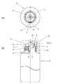
図1〜3において、Aは容器、Bは蓋体、Cは中栓である。
図1に示すように、容器Aの口部1の上部には中栓Cが嵌着され、その下方に蓋体Bが螺着されている。1-3, A is a container, B is a cover body, C is an inside stopper.
As shown in FIG. 1, an inner plug C is fitted to the upper portion of the
図1,2に示すように、容器Aの口部1は、上端内周側に立設された上部筒2と、上部筒2の下端に段部3を介して拡径し、外周面に蓋体Bと螺合するねじ部5を具えた下部筒4とからなっている。
上部筒2の外周面には、環状に突出する嵌合突条6が設けられ、その下方は、環状溝部7を介して段部3に連なっている。
下部筒4の外周面には、後述する中栓Cの摘み部14が嵌入する凹溝8が設けられており、凹溝8の底部には凸部9が設けられている。
凹溝8の底部は、摘み部14が収容されたとき蓋体Bの螺合を妨げることがないように、ねじ部5のねじ溝底部よりも深く形成されている。As shown in FIGS. 1 and 2, the
On the outer peripheral surface of the
On the outer peripheral surface of the lower cylinder 4, a
The bottom of the
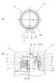
図2,3に示すように、中栓Cは、頂部を形成する頂壁10と、容器Aの口部1の内周面に気密に嵌合する内筒11と、容器Aの口部1の外周に嵌合する外筒12と、外筒12の下端にヒンジ13を介して連設する摘み部14とからなっている。
頂壁10は、上部に注出口15を開口する山部16と、山部16の下端から水平に延びる裾部17からなり、裾部17の下面には、内筒11が垂設され、裾部17の外周縁には外筒12が垂設されている。As shown in FIGS. 2 and 3, the inner plug C includes a
The
外筒12の内周下端には、容器Aの嵌合突条6に係合する係合突起20が設けられ、外筒12の外周面には、平面視で外周面が形成する円弧の一部を弦とする平坦面部21が上下方向に形成され、その下端には、薄肉のヒンジ部13を介して摘み部14が平板状に一体に連設されている。
ヒンジ部13および摘み部14は、成形時の中栓Cでは、外筒12の下端から水平方向に延びている。
摘み部14には、中央付近に凹溝8底部の凸部9に嵌合する嵌合孔22が設けられており、嵌合孔22より先端側には手指で摘みやすくするための横リブ23が設けられている。An
The
The
本実施例では、ヒンジ部13は外筒12の下端部で連設しているが、必ずしも下端部でなくともよく、例えば、平坦面部21の中程や上部で連設するなど、必要に応じて変更が可能である。
また、本実施例では、ヒンジ部13と摘み部14は同じ幅を有しているが、ヒンジ部13の幅は摘み部14のそれより狭くてもよく、平坦面部21の幅は、少なくともヒンジ13の幅以上であればよい。
さらに、本実施例では、摘み部14の嵌合孔22を凹溝8の凸部9に嵌合するようにしているが、嵌合孔22は嵌合凹部であってもよく、さらに、摘み部14の側に嵌合凸部を設け、凹溝8の側に、該嵌合凸部に嵌合する凹部を設けてもよい。In the present embodiment, the
In the present embodiment, the
Furthermore, in the present embodiment, the
本実施例では、中栓Cの係合突部20は、下端にヒンジ部13が連設された外筒12の内周側にも設けられているが、本実施例の変形例として、図2(b)に示すように、当該部位の係合突部20に切り欠き部30を設けてもよい。
このように、ヒンジ部13が連設された部位、すなわち平坦面部21に対応する部位に係合突部20が形成されていないと、摘み部14を引っ張ったときに、摘み部14が連設する付近では嵌合突条6と係合されていないので、外筒12が変形しやすく、さらに容器Aの口部1から取り外しやすくなる。
なお、係合突条20の代わりに、当該部位に対応する容器Aの嵌合突条6に、同様の趣旨で切り欠き部を設けてもよい。In the present embodiment, the engaging
As described above, when the engaging
Instead of the engaging
次に、本実施例の使用態様と作用効果について説明する。
まず、容器Aに中栓Cを装着するには、中栓Cの摘み部14と容器Aの凹溝8との周方向位置を合わせ、内筒11と外筒12との間の嵌合溝に口部1の上部筒2をあてがい、上方から押圧する。
押圧にともなって中栓Cが降下し、外筒12はわずかに変形しながら、係合突部20が嵌合突条6を乗り越えて口部1の環状溝部7に嵌合する。Next, usage modes and operational effects of this embodiment will be described.
First, in order to attach the inner stopper C to the container A, the circumferential positions of the
With the pressing, the inner plug C is lowered, and the
中栓Cの外筒12の下端から水平に延びている摘み部14を、薄肉になっているヒンジ部13で下方に折り曲げ、嵌合孔22を凹溝8の凸部9に嵌合する。
凹溝8は、摘み部14が収容されたときに、摘み部14の表面がねじ部5に螺合する蓋体のねじの山部より高くならないような深さに形成されている。
摘み部14の嵌合孔22は、わずかに締まり嵌めとなる程度に凸部9に圧入され、摘み部14が、簡単に凸部9から外れて凹溝8から飛び出さないようになっている。
そのため、蓋体Bをねじ部5に螺合して口部1に装着する際、中栓Cの摘み部14は凹溝8に確実に収容されているため、螺合の際に邪魔になることはなく、蓋体Bを繰り返し着脱しても摘み部14を損傷することはない。The
The
The
Therefore, when the lid B is screwed to the
その後、中栓Cを取り外すときには、摘み部14の先端に手指をかけて外方に引っ張り、凸部9から嵌合孔22を外して、摘み部14をヒンジ部13で上方に折り曲げて引き上げると、外筒12がわずかに変形しながら係合突部20の嵌合突条6との係合が解除され、中栓Cを口部1から取り外すことができる。
この際、外筒12の外周面に平坦面部21が形成され、その下端にヒンジ部13を介して平板状の摘み部14が連設されているので、平板状の摘み部14は、外方への曲げ変形が容易でつまみやすく、かつ、ヒンジ部13で容易に変形するので、摘み部14を凹溝8から簡単に引き出すことができるとともに、平坦面部21に対応する外筒12の肉厚が比較的小さいため、変形しやすく容易に取り外すことができる。Thereafter, when removing the inner plug C, if the finger is applied to the tip of the
At this time, since the
また、中栓Cは、摘み部14およびヒンジ部13が外筒12の下端から水平に延びた形状で成形されているので、摘み部14には常に水平方向に戻ろうとする復元力が働き、嵌合孔22と凸部9との嵌合を解除すれば、摘み部14は自律的に立ち上がって凹溝8から外れ、さらに引き出しやすくなっている。 Moreover, since the knob | pick
本実施例では、容器Aに蓋体Bを装着する係合手段として、ねじ部5を採用しているが、必ずしもねじである必要はなく、フック状の係合部など他の係合手段であってもよい。
また、本実施例では、中栓Cに注出口15を設け、注出口15を封止する蓋体Bを開閉することによって容器を使用しているが、中栓Cは注出口を有するものに限らず、単なる密封栓等であってもよく、ねじ部5に螺合して口部1に装着する部材は、蓋体に限らなくてもよい。
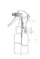
図5に示すように、中栓Cを取り外して噴射ポンプDを取り付けるようにしてもよく、本発明の中栓付き容器は、必要に応じて多様な形態で使用可能である。In this embodiment, the threaded
Further, in this embodiment, a container is used by providing a
As shown in FIG. 5, the inner plug C may be removed and the injection pump D may be attached, and the container with an inner plug of the present invention can be used in various forms as required.
次に、中栓Cの摘み部14の構成を変更した第2実施例について説明する。
以下、第1実施例と同一の構成部分には同一の符号を用い、第1実施例との相違点を中心に説明する。Next, a second embodiment in which the configuration of the
Hereinafter, the same reference numerals are used for the same components as those in the first embodiment, and the differences from the first embodiment will be mainly described.
図4に示すように、本実施例の中栓Cの摘み部14には、上面両側部に、摘み部14が凹溝8に嵌入され蓋体がねじ部5に螺合されたとき、蓋体のねじの山部に略一致する高さに突出する縦リブ24が設けられている。
摘み部14は、縦リブ24を設けることによって、蓋部Bがねじ部5に螺合されるとき、縦リブ24の表面に蓋部Bのねじ頭が当接し、凹溝8に確実に収容されるので、摘み部14が、凹溝8から浮き上がってねじ部5に噛み込まれたりすることを防止することができる。As shown in FIG. 4, when the
The
縦リブ24は、摘み部14の先端まで両側部全体にわたって設けてもよいが、摘み部14の曲げ変形を容易にしてつまみやすくするためには、図4に示す本実施例のように、摘み部14のヒンジ部13との連設部位から中央付近まで、すなわち嵌合孔22付近までとした方がよい。
本実施例は、その他の構成では実施例1と同様であり、縦リブ24による上記作用効果以外の作用効果は、実施例1と同様である。The
The present embodiment is the same as the first embodiment in other configurations, and the operational effects other than the operational effects of the
本発明の中栓付き容器は、口部に装着する中栓に引き出しやすい摘み部を設けて、中栓を取り外しやすくしているので、材質の異なる中栓を容器本体から容易に分別廃棄することができ、リサイクル用容器などに用いて好適である。
また、摘み部を容器の口部の凹溝内に確実に収容するようにしているので、蓋体を口部に係合する際に邪魔にならず、蓋体の係合によって損傷することもないため、蓋体を繰り返し着脱したり、使用時に中栓を取り外して噴射ポンプなどの他の注出具を取り付けるような容器にも、好適に利用できる。The container with an inner plug of the present invention is provided with a knob portion that can be easily pulled out on the inner plug to be attached to the mouth portion, so that the inner plug can be easily removed. It can be used for recycling containers and the like.
In addition, since the knob portion is securely accommodated in the concave groove of the mouth portion of the container, it does not get in the way when the lid body is engaged with the mouth portion, and may be damaged by the engagement of the lid body. Therefore, the container can be suitably used for a container in which the lid is repeatedly attached and detached, or the inner plug is removed during use and another dispensing tool such as an injection pump is attached.
A 容器
B 蓋体
C 中栓
D 噴射ポンプ
1 口部
2 上部筒
3 段部
4 下部筒
5 ねじ部
6 嵌合突条
7 環状溝部
8 凹溝
9 凸部
10 頂壁
11 内筒
12 外筒
13 ヒンジ部
14 摘み部
15 注出口
16 山部
17 裾部
20 係合突部
21 平坦面部
22 嵌合孔
23 横リブ
24 縦リブ
30 切り欠き部A container B lid C middle plug D injection pump 1
Claims (5)
Translated fromJapanese中栓は、頂部を形成する頂壁の下面から、容器の口部の内周面に嵌合する内筒が垂設され、頂壁の外周縁には内周下部に係合突部を有する外筒が垂設されており、
外筒の外周には、水平方向に戻ろうとする復元力を有するヒンジ部を介して平板状の摘み部が一体に連設され、摘み部には嵌合孔または嵌合凸部が設けられており、
口部は、上端内周側に立設された上部筒と、上部筒より拡径して外周面に蓋体との係合部を具えた下部筒とからなり、
上部筒は外周面に中栓の係合突部に係合する嵌合突条が設けられ、下部筒の外周面には中栓の摘み部が嵌入する凹溝が設けられており、凹溝の底部には、摘み部の嵌合孔または嵌合凸部にそれぞれ嵌合する凸部または凹部が設けられていることを特徴とする中栓付き容器。A container with an inner stopper that closely fits the inner stopper to the mouth part to which the lid can be attached,
The inner plug is suspended from the lower surface of the top wall forming the top portion, and an inner cylinder that fits to the inner peripheral surface of the mouth of the container is suspended, and the outer peripheral edge of the top wall has an engaging protrusion at the lower portion of the inner periphery. The outer cylinder is installed vertically,
On the outer periphery of the outer cylinder, a flat tab portion is integrally connected viaa hinge portionhaving a restoring force to return in thehorizontal direction, and the knob portion is provided with a fitting hole or a fitting convex portion. And
The mouth part is composed of an upper cylinder erected on the inner peripheral side of the upper end, and a lower cylinder having a diameter larger than that of the upper cylinder and having an engaging part with a lid on the outer peripheral surface,
The upper cylinder is provided with a fitting protrusion that engages with the engagement protrusion of the inner plug on the outer peripheral surface, and the outer cylinder of the lower cylinder is provided with a concave groove into which the knob portion of the inner plug is fitted. A container with a stopper is provided at the bottom of each of which a convex portion or a concave portion to be fitted into the fitting hole or the fitting convex portion of the knob portion, respectively.
Priority Applications (1)
| Application Number | Priority Date | Filing Date | Title |
|---|---|---|---|
| JP2011237770AJP5832242B2 (en) | 2011-10-28 | 2011-10-28 | Container with inner stopper |
Applications Claiming Priority (1)
| Application Number | Priority Date | Filing Date | Title |
|---|---|---|---|
| JP2011237770AJP5832242B2 (en) | 2011-10-28 | 2011-10-28 | Container with inner stopper |
Publications (2)
| Publication Number | Publication Date |
|---|---|
| JP2013095438A JP2013095438A (en) | 2013-05-20 |
| JP5832242B2true JP5832242B2 (en) | 2015-12-16 |
Family
ID=48617805
Family Applications (1)
| Application Number | Title | Priority Date | Filing Date |
|---|---|---|---|
| JP2011237770AExpired - Fee RelatedJP5832242B2 (en) | 2011-10-28 | 2011-10-28 | Container with inner stopper |
Country Status (1)
| Country | Link |
|---|---|
| JP (1) | JP5832242B2 (en) |
Families Citing this family (1)
| Publication number | Priority date | Publication date | Assignee | Title |
|---|---|---|---|---|
| JP6494425B2 (en)* | 2015-05-29 | 2019-04-03 | 株式会社吉野工業所 | Container with inner stopper |
Family Cites Families (3)
| Publication number | Priority date | Publication date | Assignee | Title |
|---|---|---|---|---|
| JP2783782B2 (en)* | 1996-03-18 | 1998-08-06 | 健一 滝沢 | Container with cap |
| JPH10287354A (en)* | 1997-04-08 | 1998-10-27 | Yoshino Kogyosho Co Ltd | Ejection plug |
| JP4043712B2 (en)* | 2000-11-30 | 2008-02-06 | 株式会社吉野工業所 | Container with plastic plastic inner stopper |
- 2011
- 2011-10-28JPJP2011237770Apatent/JP5832242B2/ennot_activeExpired - Fee Related
Also Published As
| Publication number | Publication date |
|---|---|
| JP2013095438A (en) | 2013-05-20 |
Similar Documents
| Publication | Publication Date | Title |
|---|---|---|
| US6811047B1 (en) | Closure with enhanced removal capability | |
| EP1389587B1 (en) | Bottle with a screw cap of synthetic resin | |
| JP5645213B2 (en) | Hinge cap | |
| JP7470372B2 (en) | cap | |
| JP6552447B2 (en) | Mole cap with cap | |
| JP7307529B2 (en) | hinge cap | |
| JP5049823B2 (en) | cap | |
| JP5832242B2 (en) | Container with inner stopper | |
| JP6377977B2 (en) | Extraction device for paper containers | |
| JP3938306B2 (en) | Pouring cap | |
| JP7102095B2 (en) | Screw cap with seal | |
| JP4424888B2 (en) | Combination of container and cap | |
| JP7346059B2 (en) | cap | |
| JP5900870B2 (en) | Hinge cap | |
| JPH0948446A (en) | Synthetic resin cap | |
| JP6004990B2 (en) | A spout with anti-tampering function | |
| JP7655829B2 (en) | Hinge Cap | |
| JP7220950B2 (en) | Cap seal structure | |
| JP2001072111A (en) | Pouring device | |
| JP5154293B2 (en) | Spout | |
| JP5284216B2 (en) | Finger ring | |
| JP6857551B2 (en) | Inner plug with spout | |
| JP2001072109A (en) | Synthetic resin cap | |
| JP4815981B2 (en) | Inner stopper and cap with inner stopper | |
| JP4802656B2 (en) | Synthetic resin cap |
Legal Events
| Date | Code | Title | Description |
|---|---|---|---|
| A621 | Written request for application examination | Free format text:JAPANESE INTERMEDIATE CODE: A621 Effective date:20140428 | |
| RD02 | Notification of acceptance of power of attorney | Free format text:JAPANESE INTERMEDIATE CODE: A7422 Effective date:20140508 | |
| RD04 | Notification of resignation of power of attorney | Free format text:JAPANESE INTERMEDIATE CODE: A7424 Effective date:20140528 | |
| A977 | Report on retrieval | Free format text:JAPANESE INTERMEDIATE CODE: A971007 Effective date:20150121 | |
| A131 | Notification of reasons for refusal | Free format text:JAPANESE INTERMEDIATE CODE: A131 Effective date:20150203 | |
| A521 | Request for written amendment filed | Free format text:JAPANESE INTERMEDIATE CODE: A523 Effective date:20150401 | |
| TRDD | Decision of grant or rejection written | ||
| A01 | Written decision to grant a patent or to grant a registration (utility model) | Free format text:JAPANESE INTERMEDIATE CODE: A01 Effective date:20151027 | |
| A61 | First payment of annual fees (during grant procedure) | Free format text:JAPANESE INTERMEDIATE CODE: A61 Effective date:20151027 | |
| R150 | Certificate of patent or registration of utility model | Ref document number:5832242 Country of ref document:JP Free format text:JAPANESE INTERMEDIATE CODE: R150 | |
| LAPS | Cancellation because of no payment of annual fees |