JP5827577B2 - Fiber optic connector - Google Patents
Fiber optic connectorDownload PDFInfo
- Publication number
- JP5827577B2 JP5827577B2JP2012019032AJP2012019032AJP5827577B2JP 5827577 B2JP5827577 B2JP 5827577B2JP 2012019032 AJP2012019032 AJP 2012019032AJP 2012019032 AJP2012019032 AJP 2012019032AJP 5827577 B2JP5827577 B2JP 5827577B2
- Authority
- JP
- Japan
- Prior art keywords
- optical fiber
- connector housing
- adapter
- lock arm
- connector
- Prior art date
- Legal status (The legal status is an assumption and is not a legal conclusion. Google has not performed a legal analysis and makes no representation as to the accuracy of the status listed.)
- Expired - Fee Related
Links
- 239000000835fiberSubstances0.000titleclaimsdescription8
- 239000013307optical fiberSubstances0.000claimsdescription120
- 230000013011matingEffects0.000description5
- 238000000034methodMethods0.000description2
- 238000000465mouldingMethods0.000description2
- 230000003287optical effectEffects0.000description2
- 229920003002synthetic resinPolymers0.000description2
- 239000000057synthetic resinSubstances0.000description2
- 239000000853adhesiveSubstances0.000description1
- 230000001070adhesive effectEffects0.000description1
- 230000000694effectsEffects0.000description1
- 239000011435rockSubstances0.000description1
- 239000007787solidSubstances0.000description1
Images


Landscapes
- Mechanical Coupling Of Light Guides (AREA)
- Optical Couplings Of Light Guides (AREA)
Description
Translated fromJapanese弾性的に変位する片持ち梁状の弾性ロックアームが嵌合相手のアダプタ側に設けられている場合に、弾性ロックアームによるロック解除を容易に行うことができる光ファイバコネクタに関する。 The present invention relates to an optical fiber connector that can be easily unlocked by an elastic lock arm when an elastically displaced cantilever elastic lock arm is provided on the mating adapter side.
光ファイバを有する光ファイバケーブルは、高速通信及びデータ通信に使用され、対向する光ファイバケーブルの端部には、一対の光ファイバコネクタが設けられる。これら一対の光ファイバコネクタは、アダプタを介して相互接続されるのが一般的である。
ここで、一対の光ファイバコネクタのうち一方の光ファイバコネクタは、アダプタの一端側からアダプタに嵌合され、他方の光ファイバコネクタは、アダプタの他端側からアダプタに嵌合される。そして、アダプタに嵌合された一対の光ファイバコネクタは、それぞれ、アダプタ及び各光ファイバコネクタに設けられたロック機構によりロックされ、また、そのロック状態が解除されるようになっている。An optical fiber cable having an optical fiber is used for high-speed communication and data communication, and a pair of optical fiber connectors are provided at the ends of the opposing optical fiber cables. These pair of optical fiber connectors are generally interconnected via an adapter.
Here, one optical fiber connector of the pair of optical fiber connectors is fitted to the adapter from one end side of the adapter, and the other optical fiber connector is fitted to the adapter from the other end side of the adapter. The pair of optical fiber connectors fitted to the adapter are locked by a lock mechanism provided in the adapter and each optical fiber connector, and the locked state is released.
従来、ロック状態を解除する機能を有する光ファイバコネクタとして、例えば、図7(A),(B)に示すものが知られている(特許文献1参照)。
図7(A),(B)に示す光ファイバコネクタ100は、コネクタハウジング110と、コネクタハウジング110にスライド可能に装着されるカバー120とを備えている。コネクタハウジング110には、図示しない光ファイバケーブルの光ファイバが支持されるフェルール117が設けられている。また、コネクタハウジング110の両側壁には、弾性アーム114が設けられている。弾性アーム114の先端には、カバー120に形成された開口121内に位置してカバー120の前方(図7(B)における左方)への移動を規制する係止突起115が設けられている。また、コネクタハウジング110の後端には、カバー120の後端(図7(B)における右端)が当接してカバー120の後方への移動を規制するストッパ突起116が設けられている。Conventionally, as an optical fiber connector having a function of releasing a lock state, for example, one shown in FIGS. 7A and 7B is known (see Patent Document 1).
An
そして、コネクタハウジング110の前方部には、接続相手(図示せず)の係合部分をロックする、弾性的に変位する片持ち梁状の弾性ロックアーム111が設けられている。弾性ロックアーム111は、コネクタハウジング110の前方部から前方に延び、その先端に前記係合部分をロックするロック突起112が設けられている。そして、弾性ロックアーム111の中間部分には、傾斜部113が設けられている。 An elastically displaceable cantilevered
また、カバー120には、カバー120を後方へスライドさせたときに、弾性ロックアーム111の傾斜部113を押圧して弾性ロックアーム111を下方へ押し下げる押圧部122が設けられている。また、カバー120の後端部には、カバー120をコネクタハウジング110に対してスライド操作するための平坦な帯状の操作摘み130が設けられている。Further, the
そして、光ファイバコネクタ100が接続相手に嵌合している状態で、操作摘み130を後方へ引張操作する。これにより、カバー120が後方へスライドし、カバー120の押圧部122が弾性ロックアーム111の傾斜部113を押圧して弾性ロックアーム111を下方へ押し下げる。これにより、弾性ロックアーム111による接続相手とのロック状態を解除することができる。 Then, the
また、ロック状態を解除する機能を有する光ファイバコネクタとして、例えば、特許文献2に示すもの(図示せず)も知られている。
特許文献2に示す光ファイバコネクタは、コネクタハウジングと、コネクタハウジングに嵌合離脱方向にスライド可能に保持されたスライドカバーとを備えている。コネクタハウジングには、光送受信モジュールの孔にロックされる被ロック部を有する、弾性的に変位する片持ち梁状の弾性ロックアームが設けられている。また、弾性ロックアームには、被ロック部のロック解除を行うための被操作部が設けられている。一方、スライドカバーには、弾性ロックアームの被操作部と当接する当接部が設けられている。そして、スライドカバーが嵌合離脱方向にスライドすると、当接部が被操作部を操作して被ロック部のロック解除を行うようになっている。Further, as an optical fiber connector having a function of releasing a lock state, for example, the one shown in Patent Document 2 (not shown) is also known.
The optical fiber connector shown in Patent Document 2 includes a connector housing and a slide cover that is slidably held in the connector housing in a fitting / removing direction. The connector housing is provided with an elastically displaced cantilevered elastic lock arm having a locked portion that is locked in the hole of the optical transceiver module. Further, the elastic lock arm is provided with an operated part for unlocking the locked part. On the other hand, the slide cover is provided with a contact portion that contacts the operated portion of the elastic lock arm. When the slide cover slides in the fitting / removing direction, the contact portion operates the operated portion to unlock the locked portion.
しかしながら、この従来の図7(A),(B)に示した特許文献1に記載された光ファイバコネクタ100及び特許文献2に記載された光ファイバコネクタにあっては、以下の問題点があった。
即ち、図7(A),(B)に示した特許文献1に記載の光ファイバコネクタ100の場合、弾性的に変位する片持ち梁状の弾性ロックアーム111が光ファイバコネクタ100(コネクタハウジング110)自身に設けられている。従って、接続相手側に弾性的に変位する片持ち梁状の弾性ロックアームが設けられている場合には、図7(A),(B)に示した特許文献1に記載のカバー120によっては、ロック解除を行うことができない。However, the
That is, in the case of the
また、特許文献2に記載の光ファイバコネクタの場合も、弾性的に変位する片持ち梁状の弾性ロックアームが光ファイバコネクタ(コネクタハウジング)自身に設けられている。従って、相手側である光送受信モジュールに弾性的に変位する片持ち梁状の弾性ロックアームが設けられている場合には、特許文献2に記載のスライドカバーによっては、ロック解除を行うことができない。 Also in the case of the optical fiber connector described in Patent Document 2, an elastic lock arm in the form of a cantilever that is elastically displaced is provided on the optical fiber connector (connector housing) itself. Therefore, when the optical transmitting / receiving module on the other side is provided with a cantilever-like elastic lock arm that is elastically displaced, the unlocking cannot be performed by the slide cover described in Patent Document 2. .
近年においては、光ファイバコネクタ自身の構造、構成を簡単にするために、弾性ロックアームを相手接続側に設ける要請する場合が多々ある。このような場合に、弾性ロックアームのロック解除を簡単かつ容易な操作で行うことが好ましい。
従って、本発明はこの問題点に鑑みてなされたものであり、その目的は、弾性的に変位する片持ち梁状の弾性ロックアームが嵌合相手のアダプタ側に設けられている場合に、弾性ロックアームによるロック解除を容易に行うことができる光ファイバコネクタを提供することにある。In recent years, in order to simplify the structure and configuration of the optical fiber connector itself, there are many cases where an elastic lock arm is required to be provided on the counterpart connection side. In such a case, it is preferable to unlock the elastic lock arm with a simple and easy operation.
Therefore, the present invention has been made in view of this problem, and the object thereof is to provide an elastic structure when an elastically displaced cantilever-like elastic lock arm is provided on the mating adapter side. An object of the present invention is to provide an optical fiber connector that can be easily unlocked by a lock arm.
上記目的を達成するために、本発明のうち請求項1に係る光ファイバコネクタは、弾性的に変位する片持ち梁状の弾性ロックアームを有するアダプタに嵌合されるコネクタハウジングを有する光ファイバコネクタであって、前記コネクタハウジングが前記アダプタに嵌合された際に、前記弾性ロックアームが前記コネクタハウジングをロックする光ファイバコネクタにおいて、前記コネクタハウジングに、引張操作によって、前記弾性ロックアームの前記コネクタハウジングに対するロック状態を解除する、可撓性を有するプルタブを固着し、前記コネクタハウジングに、前記弾性ロックアームが前記コネクタハウジングをロックする際に、前記弾性ロックアームが係合する、光ファイバケーブルが延びる方向に対して交差する方向に延びる肩部を形成し、前記プルタブは、前記弾性ロックアームが前記コネクタハウジングをロックする際に、前記肩部と前記弾性ロックアームの一部との間に配置されるように、前記コネクタハウジングに固着されることを特徴としている。To achieve the above object, an optical fiber connector according to claim 1 of the present invention has an optical fiber connector having a connector housing fitted to an adapter having an elastically displaced cantilever-like elastic lock arm. In the optical fiber connector in which the elastic lock arm locks the connector housing when the connector housing is fitted to the adapter, the connector of the elastic lock arm is pulled by the connector housing.Anoptical fiber cable, whereina flexible pull tab that releases a locked state with respect to the housing is fixed,and the elastic lock arm is engagedwith the connector housing when the elastic lock arm locks the connector housing. Extends in a direction that intersects the direction of extension The pull tab is secured to the connector housing such that the pull tab is disposed between the shoulder and a portion of the elastic lock arm when the elastic lock arm locks the connector housing. it is characterized in thatthat.
また、本発明のうち請求項2に係る光ファイバコネクタは、請求項1記載の光ファイバコネクタにおいて、前記プルタブは、前記コネクタハウジングに固着される平板状の固着部と、該固着部から前記コネクタハウジングの端部を超えて光ファイバケーブルが延びる方向と平行方向に延びる摘み部とを備えることを特徴としている。
更に、本発明のうち請求項3に係る光ファイバコネクタは、請求項2記載の光ファイバコネクタにおいて、前記摘み部が、前記固着部に対して直交する平板状に形成されていることを特徴としている。The optical fiber connector according to claim2 of the present invention is to provide an optical fiber connector according to claim1, wherein the pull tab, a flat fixing portion which is fixed to the connector housing, the connector from the solid attachment part It is characterized by comprising a knob extending in a direction parallel to the direction in which the optical fiber cable extends beyond the end of the housing.
Furthermore, the optical fiber connector according to
本発明に係る光ファイバコネクタによれば、コネクタハウジングに、引張操作によって、嵌合相手のアダプタ側に設けられた弾性ロックアームのコネクタハウジングに対するロック状態を解除するプルタブを固着した。このため、弾性的に変位する片持ち梁状の弾性ロックアームが嵌合相手のアダプタ側に設けられている場合に、プルタブの引張操作によって、弾性ロックアームによるロック解除を容易に行うことができる。 According to the optical fiber connector of the present invention, the pull tab for releasing the locked state of the elastic lock arm provided on the mating adapter side with respect to the connector housing is fixed to the connector housing by a pulling operation. For this reason, when the elastically displaced cantilever-like elastic lock arm is provided on the adapter side of the mating counterpart, the lock release by the elastic lock arm can be easily performed by pulling the pull tab. .
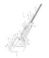
以下、本発明に係る光ファイバコネクタの第1実施形態を図1乃至4を参照して説明する。
図1乃至図5において、光ファイバコネクタ1は、アダプタ50の一端側(図1における右側、前側)からアダプタ50内に嵌合する。一方、アダプタ50の他端側(後側)には、アダプタ50とは別個のアダプタ(図示せず)が取り付けられる。そして、光ファイバコネクタ1とは別個の光ファイバコネクタが、アダプタ50の他端側から前記別個のアダプタ内に嵌合し、光ファイバコネクタ1に相互接続される。
ここで、アダプタ50は、アダプタ本体60と、アダプタ本体60の前側に固着されたアダプタカバー70とを備えている。
アダプタカバー70は、図1乃至図5に示すように、アダプタ本体60の前側に固着される固着部71と、フード部73と、弾性ロックアーム74とを備えている。アダプタカバー70は、合成樹脂を成形することによって一体に形成される。Hereinafter, a first embodiment of an optical fiber connector according to the present invention will be described with reference to FIGS.
1 to 5, the optical fiber connector 1 is fitted into the
Here, the
As shown in FIGS. 1 to 5, the
固着部71は、略矩形の平板状に形成され、図3乃至図5に示すように、略中央に矩形状の開口72を備えている。開口72は、アダプタ本体60の後述する突出部62が挿通可能になっている。開口72を挟んだ固着部71の上下両側には、固着部71をアダプタ本体60に対して固着するための取付ねじ(図示せず)が挿通される1対の取付ねじ用貫通孔71aが形成されている。
また、フード部73は、固着部71の開口72の周囲から前方に延びる四角筒状に形成され、後方からアダプタ本体60の突出部62を受容可能になっている。また、フード部73は、前方から光ファイバコネクタ1を受容可能となっている。The adhering
Further, the
更に、弾性ロックアーム74は、固着部71の開口72の上端縁から前方、即ちフード部73内に片持ち梁状に延びる。弾性ロックアーム74は、図3及び図4に示すように、アダプタ50に嵌合された光ファイバコネクタ1のコネクタハウジング10をロックする機能を有する。弾性ロックアーム74の先端(前端)には、図3に示すように、弾性ロックアーム74がコネクタハウジング10をロックする際に、コネクタハウジング10に形成された後述の肩部13との間でプルタブ40を部分的に挟持するプルタブ係合部(弾性ロックアームの一部)75が設けられている。そして、プルタブ係合部75の幅方向(図3及び図4において紙面に対して直交する方向)両端の内側面(肩部13と対向する面)には、弾性ロックアーム74がコネクタハウジング10をロックする際に、コネクタハウジング10に形成された肩部13に係合する1対のロック突起76が設けられている。弾性ロックアーム74において、光ファイバコネクタ1がアダプタ50に嵌合される際に、光ファイバコネクタ1がロック突起76に当接する。これにより、光ファイバコネクタ1の嵌合が進行可能なように弾性ロックアーム74が上方(外方)へ弾性的に変位する。そして、光ファイバコネクタ1の嵌合が完了すると、弾性ロックアーム74がほぼ元の状態に復元し、ロック突起76が肩部13に係合する。 Further, the
また、アダプタカバー70が取り付けられるアダプタ本体60は、略直方体状のアダプタ本体部61と、アダプタ本体部61の前面上下方向略中央部から前方に延びる略四角筒状の突出部62とを備えている。アダプタ本体60は、合成樹脂を成形することによって形成される。そして、アダプタ本体部61の後面から突出部62の前面にかけて光ファイバコネクタ受容孔63が貫通している。アダプタ本体部61の上端部及び下端部には、固着部71をアダプタ本体60に対して固着するための取付ねじが螺合される1対の溝64が設けられている。各溝64は、アダプタ本体部61の前面から後面にかけて貫通している。更に、突出部62の上壁及び下壁には、光ファイバコネクタ1に形成されたディテント部12を受容する1対のロック用開口65が形成されている。ディテント部12は、ロック用開口65内に突出する、ラッチアーム66の突起66aに係合する。なお、アダプタ本体部61の後端面には、図示しない別個のアダプタが取り付けられる。 The adapter
また、光ファイバコネクタ1は、レンズ付き多心光ファイバコネクタと呼ばれ、図1及び図3に示すように、アダプタ50に嵌合されるコネクタハウジング10と、レンズ付き多心フェルール20と、光ファイバケーブル30とを備えている。コネクタハウジング10には、フェルール受容キャビティ11が設けられている。フェルール受容キャビティ11は、図3に示すように、コネクタハウジング10の前面(図3における左面)に開口し、コネクタハウジング10の後方に向けて延びている。フェルール受容キャビティ11内には、レンズ付き多心フェルール20が前後方向に移動可能に設けられている。レンズ付き多心フェルール20は、フェルール受容キャビティ11内に設けられたばね(図示せず)により前方側に付勢され、その前端面がコネクタハウジング11の前端面から若干突出する。更に、光ファイバケーブル30は、図3に示すように、多数の光ファイバ31がレンズ付き多心フェルール20に支持されてコネクタハウジング10から後方に導出される。 The optical fiber connector 1 is called a multi-fiber optical fiber connector with a lens. As shown in FIGS. 1 and 3, a
そして、コネクタハウジング10の上下両面には、図1、図3及び図5に示すように、コネクタハウジング10の前端面から後方に向けて延びる一対の凹部14が形成されている。また、コネクタハウジング10の各凹部14の後側よりの部分には、アダプタ本体60の突出部62に形成されたロック用開口65に受容される1対のディテント部12が突出形成されている。各ディテント部12の凹部14の底からの突出高さは、各ディテント部12の頂部がコネクタハウジング10の上下面と面一になる高さである。 A pair of
更に、コネクタハウジング10の上面のディテント部12よりも後側の部分には、図3に示すように、肩部13が形成されている。肩部13は、弾性ロックアーム74がコネクタハウジング10をロックする際に、弾性ロックアーム74のロック突起76が係合する。肩部13は、光ファイバケーブル30が延びる方向に対して直交する方向に延びている。 Further, as shown in FIG. 3, a
また、コネクタハウジング10の上面の凹部14の後側には、引張操作によって弾性ロックアーム74のコネクタハウジング10に対するロック状態を解除し光ファイバコネクタ1を抜去する平坦な帯状のプルタブ40が固着されている。プルタブ40は、図3に示すように、弾性ロックアーム74がコネクタハウジング10をロックする際に、肩部13とプルタブ係合部75との間に配置されるように、コネクタハウジング10に固着される。プルタブ40は可撓性を有し、肩部13のところで一対のロック突起76間を通るようになっている。プルタブ40は、接着剤、図示しないピン等によりコネクタハウジング10に固着される。プルタブ40は、図1に示すように、コネクタハウジング10に固着される平板状の固着部41と、固着部41からコネクタハウジング10の端部を超えて光ファイバケーブル30が延びる方向と平行方向に延びる摘み部42とを備えている。摘み部42は、固着部41に対して平行な平板状に形成されている。 Further, a flat belt-
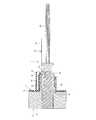
次に、光ファイバコネクタ1のアダプタ50への接続及びロック解除方法について図3乃至図5を参照して説明する。
先ず、アダプタ本体60の前側にアダプタカバー70を固着し、アダプタ50を完成させる。
次いで、図3及び図4に示すように、光ファイバコネクタ1をアダプタ50に嵌合する。この嵌合作業に際しては、光ファイバコネクタ1のコネクタハウジング10を、アダプタ本体60の光ファイバコネクタ受容孔63内にアダプタ50の前側から挿入する。これにより、コネクタハウジング10に設けられたディテント部12がアダプタ本体60のラッチアーム66の突起66aに係合し、光ファイバコネクタ1がアダプタ本体60に対してロックされる。また、このとき同時に、アダプタカバー70に設けられた弾性ロックアーム74の一対のロック突起76がコネクタハウジング10の肩部13に係合し、弾性ロックアーム74がコネクタハウジング10をロックする。この際に、図3に示すように、弾性ロックアーム74のプルタブ係合部75と肩部13との間にプルタブ40が配置される。これにより、光ファイバコネクタ1はアダプタ50に接続される。Next, a method for connecting the optical fiber connector 1 to the
First, the
Next, as shown in FIGS. 3 and 4, the optical fiber connector 1 is fitted into the
一方、アダプタ50の後側には、アダプタ50とは別個の図示しないアダプタがアダプタ50に取り付けられている。そして、光ファイバコネクタ1とは別個の光ファイバコネクタを、アダプタ50の後側から前記別個のアダプタ内に嵌合させると、この光ファイバコネクタが光ファイバコネクタ10に相互接続される。
そして、弾性ロックアーム74によるコネクタハウジング10に対するロック状態を解除する際には、プルタブ40の摘み部42を摘んで引っ張る。すると、図5に示すように、プルタブ40がプルタブ係合部75と係合することによって弾性ロックアーム74が上方(外方)に弾性的に変位し、ロック突起76による肩部13に対する係合状態が解かれる。これにより、弾性ロックアーム74によるコネクタハウジング10に対するロック状態が解除され、光ファイバコネクタ1が抜去できる。On the other hand, an adapter (not shown) separate from the
And when releasing the locked state with respect to the
従って、本実施形態に係る光ファイバコネクタ1によれば、弾性的に変位する片持ち梁状の弾性ロックアーム74が嵌合相手のアダプタ50側に設けられている場合に、プルタブ40の引張操作によって、弾性ロックアーム74によるロック解除を容易に行うことができる。
ここで、弾性ロックアーム74がコネクタハウジング10をロックしている際には、弾性ロックアーム74のプルタブ係合部75と肩部13との間にプルタブ40が配置されている。肩部13は、光ファイバケーブル30が延びる方向に対して直交する方向に延びている。このため、プルタブ40を、光ファイバケーブル30が延びる方向に対して斜め上方、斜め下方、あるいは水平のいずれの方向に引っ張っても弾性ロックアーム74が上方(外方)に容易に弾性変形する。従って、ロック突起76による肩部13に対する係合状態を簡単かつ容易に解除することができる。Therefore, according to the optical fiber connector 1 according to the present embodiment, when the elastically displaced cantilever-like
Here, when the
また、プルタブ40の摘み部42は、固着部41からコネクタハウジング10の端部を超えて光ファイバケーブル30が延びる方向と平行方向に延びている。このため、摘み部42を摘んでプルタブ40を引っ張る際に、コネクタハウジング10が邪魔にならずに容易に摘み部42を摘むことができ、プルタブ40の引張操作を容易に行うことができる。
そして、プルタブ40の引張操作を続行すると、コネクタハウジング10に設けられたディテント部12の突起66aに対する係合状態が解かれ、光ファイバコネクタ1をアダプタ50から抜去することができる。Further, the
When the pulling operation of the
次に、本発明に係る光ファイバコネクタの第2実施形態を図6を参照して説明する。図6において、図1乃至図5に示す構成部材と同様の構成部材については同一の符号を付し、その説明を省略することがある。
図6に示す光ファイバコネクタ1は、図1に示す光ファイバコネクタ1と基本構成は同様であるが、プルタブ40の形状が図1に示す光ファイバコネクタ1におけるプルタブ40の形状と異なっている。Next, a second embodiment of the optical fiber connector according to the present invention will be described with reference to FIG. In FIG. 6, the same components as those shown in FIGS. 1 to 5 are denoted by the same reference numerals, and the description thereof may be omitted.
The optical fiber connector 1 shown in FIG. 6 has the same basic configuration as the optical fiber connector 1 shown in FIG. 1, but the shape of the
即ち、光ファイバコネクタ1を構成するコネクタハウジング10の上面の凹部14の後側には、引張操作によって弾性ロックアーム74のコネクタハウジング10に対するロック状態を解除する平坦な帯状のプルタブ40が固着されている。プルタブ40は、図1に示す光ファイバコネクタ1におけるプルタブ40と同様に、弾性ロックアーム74がコネクタハウジング10をロックする際に、肩部13とプルタブ係合部75との間に配置されるように、コネクタハウジング10に固着される。そして、プルタブ40は、コネクタハウジング10に固着される平板状の固着部41と、固着部41からコネクタハウジング10の端部を超えて光ファイバケーブル30が延びる方向と平行方向に延びる摘み部42とを備えている。 That is, a flat belt-
ここで、摘み部42は、図1に示す光ファイバコネクタ1におけるプルタブ40の摘み部42と異なり、固着部41に対して直交する平板状に形成されている。
この図6に示す光ファイバコネクタ1が接続されるアダプタ50は、図1に示すアダプタ50と異なり、複数の光ファイバコネクタ1を固着部41の平面方向に一列状に受容するようになっている。このため、アダプタカバー70は、複数の弾性ロックアーム74を有している。また、アダプタカバー70が取り付けられるアダプタ本体60においては、アダプタ本体部61の後面から突出部62の前面にかけて複数の光ファイバコネクタ受容孔63が貫通している。複数の光ファイバコネクタ受容孔63は、固着部41の平面方向に一列状に形成されている。更に、突出部62の上壁及び下壁であって各光ファイバコネクタ受容孔63に対応する位置には、複数の光ファイバコネクタ1に形成された複数のディテント部12が係合する複数対のロック用開口(図示せず)が形成されている。Here, unlike the
The
次に、光ファイバコネクタ1のアダプタ50への接続及びロック解除方法について図6を参照して説明する。
先ず、アダプタ本体60の前側にアダプタカバー70を固着し、アダプタ50を完成させる。
次いで、各光ファイバコネクタ1をアダプタ50に嵌合する。この嵌合作業に際しては、各光ファイバコネクタ1のコネクタハウジング10を、アダプタ本体60の各光ファイバコネクタ受容孔63内にアダプタ50の前側から挿入する。これにより、各コネクタハウジング10に設けられたディテント部12がアダプタ本体60のラッチアーム66の突起66aに係合し、各光ファイバコネクタ1がアダプタ本体60に対してロックされる。また、このとき同時に、アダプタカバー70に設けられた各弾性ロックアーム74のロック突起76が各コネクタハウジング10の肩部13に係合し、各弾性ロックアーム74が各コネクタハウジング10をロックする。この際に、各弾性ロックアーム74のプルタブ係合部75と肩部13との間に各プルタブ40が配置される。これにより、各光ファイバコネクタ1はアダプタ50に接続される。Next, a method for connecting the optical fiber connector 1 to the
First, the
Next, each optical fiber connector 1 is fitted into the
そして、各弾性ロックアーム74による各コネクタハウジング10に対するロック状態を解除する際には、各プルタブ40の摘み部42を摘んで引っ張る。すると、各プルタブ40がプルタブ係合部75と係合することによって各弾性ロックアーム74が上方(外方)に弾性的に変位し、各ロック突起76による肩部13に対する係合状態が解かれる。これにより、各弾性ロックアーム74による各コネクタハウジング10に対するロック状態が解除される。 And when releasing the locked state with respect to each
ここで、摘み部42は、図1に示す光ファイバコネクタ1におけるプルタブ40の摘み部42と異なり、固着部41に対して直交する平板状に形成されている。従って、アダプタ50が複数の光ファイバコネクタ1を固着部41の平面方向に一列状に受容している状態で、各プルタブ40の摘み部42を摘んで引っ張る際に、隣接するプルタブ40の摘み部42同士が干渉せずに容易に摘み部42を引っ張ることができる。 Here, unlike the
また、各弾性ロックアーム74がコネクタハウジング10をロックしている際には、各弾性ロックアーム74のプルタブ係合部75と各肩部13との間にプルタブ40が配置されている。各肩部13は、光ファイバケーブル30が延びる方向に対して直交する方向に延びている。このため、各プルタブ40を、光ファイバケーブル30が延びる方向に対して斜め上方、斜め下方、あるいは水平のいずれの方向に引っ張っても各弾性ロックアーム74が上方(外方)に容易に弾性変形する。従って、各ロック突起76による肩部13に対する係合状態を簡単かつ容易に解除することができる。 In addition, when each
また、各プルタブ40の摘み部42は、固着部41からコネクタハウジング10の端部を超えて光ファイバケーブル30が延びる方向と平行方向に延びている。このため、各摘み部42を摘んでプルタブ40を引っ張る際に、コネクタハウジング10が邪魔にならずに容易に各摘み部42を摘むことができ、各プルタブ40の引張操作を容易に行うことができる。 Further, the
以上、本発明の実施形態について説明してきたが、本発明はこれに限定されずに種々の変更、改良を行うことができる。
例えば、プルタブ40は、コネクタハウジング10に固着されるとともに、引張操作によって、弾性ロックアーム74のコネクタハウジング10に対するロック状態を解除するものであればよく、必ずしも平坦な帯状に形成される必要はない。プルタブ40は、例えば紐状であってもよい。As mentioned above, although embodiment of this invention has been described, this invention is not limited to this, A various change and improvement can be performed.
For example, the
また、プルタブ40は、必ずしも、平板状の固着部41と、固着部41からコネクタハウジング10の端部を超えて光ファイバケーブル30が延びる方向と平行方向に延びる摘み部42とを備えていなくても良い。
また、コネクタハウジング10に形成される肩部13は、必ずしも光ファイバケーブル30が延びる方向に対して直交する方向に延びる必要はなく、当該光ファイバケーブル30が延びる方向に対して交差する方向に延びていればよい。Further, the
The
また、プルタブ40は、弾性ロックアーム74がコネクタハウジング10をロックする際に、肩部13とプルタブ係合部75との間に配置されるように、コネクタハウジング10に固着される必要は必ずしもない。
さらに、プルタブ40は、一対のロック突起76間ではなく、1個のロック突起76近傍を通ってもよい。Further, the
Furthermore, the
また、プルタブ係合部75の幅方向両端に一対のロック突起76が設けられているが、プルタブ係合部75は肩部13との間にプルタブ40を配置するように弾性ロックアーム74の一部に形成されていればよく、ロック突起76と離れていてもかまわない。
また、アダプタ50は、アダプタ本体60と、アダプタカバー70との二体により構成されているが、一体により構成してもよい。
また、光ファイバコネクタ1は、レンズ多心光ファイバコネクタに限らず、SC形等の他の光ファイバコネクタであってもよい。一方、アダプタ50に嵌合する別個の光ファイバコネクタは、SC形、FC形、MPO形等種々の光ファイバコネクタを適用できる。In addition, a pair of
Moreover, although the
The optical fiber connector 1 is not limited to a lens multi-fiber optical fiber connector, but may be another optical fiber connector such as an SC type. On the other hand, various optical fiber connectors such as SC type, FC type, and MPO type can be applied to the separate optical fiber connector fitted to the
1 光ファイバコネクタ
10 コネクタハウジング
13 肩部
30 光ファイバケーブル
40 プルタブ
41 固着部
42 摘み部
50 アダプタ
74 弾性ロックアーム
75 プルタブ係合部(弾性ロックアームの一部)DESCRIPTION OF SYMBOLS 1
Claims (3)
Translated fromJapanese前記コネクタハウジングに、引張操作によって、前記弾性ロックアームの前記コネクタハウジングに対するロック状態を解除する、可撓性を有するプルタブを固着し、
前記コネクタハウジングに、前記弾性ロックアームが前記コネクタハウジングをロックする際に、前記弾性ロックアームが係合する、光ファイバケーブルが延びる方向に対して交差する方向に延びる肩部を形成し、前記プルタブは、前記弾性ロックアームが前記コネクタハウジングをロックする際に、前記肩部と前記弾性ロックアームの一部との間に配置されるように、前記コネクタハウジングに固着されることを特徴とする光ファイバコネクタ。An optical fiber connector having a connector housing fitted to an adapter having an elastically displaced cantilever-like elastic lock arm, wherein the elastic lock arm when the connector housing is fitted to the adapter In the optical fiber connector that locks the connector housing,
Aflexible pull tab that releases the locked state of the elastic lock arm to the connector housing by a pulling operation is fixedto the connector housing,
The pull-tab is formed on the connector housing so as to extend in a direction intersecting with a direction in which an optical fiber cable extends, with which the elastic lock arm engages when the elastic lock arm locks the connector housing. Is fixed to the connector housing so as to be disposed between the shoulder and a part of the elastic lock arm when the elastic lock arm locks the connector housing. Fiber connector.
Priority Applications (1)
| Application Number | Priority Date | Filing Date | Title |
|---|---|---|---|
| JP2012019032AJP5827577B2 (en) | 2012-01-31 | 2012-01-31 | Fiber optic connector |
Applications Claiming Priority (1)
| Application Number | Priority Date | Filing Date | Title |
|---|---|---|---|
| JP2012019032AJP5827577B2 (en) | 2012-01-31 | 2012-01-31 | Fiber optic connector |
Publications (2)
| Publication Number | Publication Date |
|---|---|
| JP2013156580A JP2013156580A (en) | 2013-08-15 |
| JP5827577B2true JP5827577B2 (en) | 2015-12-02 |
Family
ID=49051773
Family Applications (1)
| Application Number | Title | Priority Date | Filing Date |
|---|---|---|---|
| JP2012019032AExpired - Fee RelatedJP5827577B2 (en) | 2012-01-31 | 2012-01-31 | Fiber optic connector |
Country Status (1)
| Country | Link |
|---|---|
| JP (1) | JP5827577B2 (en) |
Families Citing this family (23)
| Publication number | Priority date | Publication date | Assignee | Title |
|---|---|---|---|---|
| CN111051945B (en) | 2017-06-28 | 2023-12-29 | 康宁研究与开发公司 | Compact fiber optic connector, cable assembly and method of making the same |
| US11668890B2 (en) | 2017-06-28 | 2023-06-06 | Corning Research & Development Corporation | Multiports and other devices having optical connection ports with securing features and methods of making the same |
| US12271040B2 (en) | 2017-06-28 | 2025-04-08 | Corning Research & Development Corporation | Fiber optic extender ports, assemblies and methods of making the same |
| US11187859B2 (en) | 2017-06-28 | 2021-11-30 | Corning Research & Development Corporation | Fiber optic connectors and methods of making the same |
| US11300746B2 (en) | 2017-06-28 | 2022-04-12 | Corning Research & Development Corporation | Fiber optic port module inserts, assemblies and methods of making the same |
| US10359577B2 (en) | 2017-06-28 | 2019-07-23 | Corning Research & Development Corporation | Multiports and optical connectors with rotationally discrete locking and keying features |
| JP7136129B2 (en)* | 2018-01-23 | 2022-09-13 | 住友電気工業株式会社 | Optical connection structure, optical connector part, and housing |
| US10641967B1 (en) | 2018-11-16 | 2020-05-05 | Corning Research & Development Corporation | Multiport assemblies including a modular adapter support array |
| US10768382B2 (en) | 2018-11-29 | 2020-09-08 | Corning Research & Development Corporation | Multiport assemblies including access apertures and a release tool |
| PT3903136T (en) | 2018-12-28 | 2024-12-05 | Corning Res & Dev Corp | Multiport assemblies including mounting features or dust plugs |
| WO2020242847A1 (en) | 2019-05-31 | 2020-12-03 | Corning Research & Development Corporation | Multiports and other devices having optical connection ports with sliding actuators and methods of making the same |
| US11294133B2 (en) | 2019-07-31 | 2022-04-05 | Corning Research & Development Corporation | Fiber optic networks using multiports and cable assemblies with cable-to-connector orientation |
| US11487073B2 (en) | 2019-09-30 | 2022-11-01 | Corning Research & Development Corporation | Cable input devices having an integrated locking feature and assemblies using the cable input devices |
| EP3805827B1 (en) | 2019-10-07 | 2025-07-30 | Corning Research & Development Corporation | Fiber optic terminals and fiber optic networks having variable ratio couplers |
| US11650388B2 (en) | 2019-11-14 | 2023-05-16 | Corning Research & Development Corporation | Fiber optic networks having a self-supporting optical terminal and methods of installing the optical terminal |
| US11536921B2 (en) | 2020-02-11 | 2022-12-27 | Corning Research & Development Corporation | Fiber optic terminals having one or more loopback assemblies |
| US11604320B2 (en) | 2020-09-30 | 2023-03-14 | Corning Research & Development Corporation | Connector assemblies for telecommunication enclosures |
| AU2021368055A1 (en) | 2020-10-30 | 2023-06-08 | Corning Research & Development Corporation | Female fiber optic connectors having a rocker latch arm and methods of making the same |
| US11880076B2 (en) | 2020-11-30 | 2024-01-23 | Corning Research & Development Corporation | Fiber optic adapter assemblies including a conversion housing and a release housing |
| US11686913B2 (en) | 2020-11-30 | 2023-06-27 | Corning Research & Development Corporation | Fiber optic cable assemblies and connector assemblies having a crimp ring and crimp body and methods of fabricating the same |
| US11994722B2 (en) | 2020-11-30 | 2024-05-28 | Corning Research & Development Corporation | Fiber optic adapter assemblies including an adapter housing and a locking housing |
| US11927810B2 (en) | 2020-11-30 | 2024-03-12 | Corning Research & Development Corporation | Fiber optic adapter assemblies including a conversion housing and a release member |
| US11947167B2 (en) | 2021-05-26 | 2024-04-02 | Corning Research & Development Corporation | Fiber optic terminals and tools and methods for adjusting a split ratio of a fiber optic terminal |
Family Cites Families (3)
| Publication number | Priority date | Publication date | Assignee | Title |
|---|---|---|---|---|
| JP4783820B2 (en)* | 2008-09-08 | 2011-09-28 | 本多通信工業株式会社 | Plug with extraction jig |
| JP5325682B2 (en)* | 2009-06-26 | 2013-10-23 | 株式会社フジクラ | Optical connector |
| CN202004269U (en)* | 2010-12-22 | 2011-10-05 | 富士康(昆山)电脑接插件有限公司 | Connector module |
- 2012
- 2012-01-31JPJP2012019032Apatent/JP5827577B2/ennot_activeExpired - Fee Related
Also Published As
| Publication number | Publication date |
|---|---|
| JP2013156580A (en) | 2013-08-15 |
Similar Documents
| Publication | Publication Date | Title |
|---|---|---|
| JP5827577B2 (en) | Fiber optic connector | |
| JP5053928B2 (en) | Optical connector plug | |
| CN104749717B (en) | Optical couping device and the optical transceiver being provided with optical couping device | |
| JP5416088B2 (en) | Connector unit | |
| US7588373B1 (en) | Optical connector plug | |
| JP5085694B2 (en) | Optical connector | |
| US8764312B2 (en) | Optical connector plug having improved latching mechanism | |
| US20120027359A1 (en) | Optical connector and connector connection system | |
| JP6170571B2 (en) | Fiber optic interconnect assembly | |
| EP2144100A1 (en) | Optical Connector Plug | |
| JP6363781B1 (en) | Plug and cable with plug | |
| US20160282566A1 (en) | Hybrid connector for both electrical and optical transmission | |
| WO2016067827A1 (en) | Plug, receptacle, and connector | |
| JP2009222932A (en) | Connector | |
| US11422315B2 (en) | Optical connector system | |
| JP5059068B2 (en) | Removable tool | |
| US10914899B2 (en) | Optical connector and method for connecting optical connector | |
| WO2019107110A1 (en) | Optical connector and method for connecting optical connector | |
| CN113296197B (en) | Locking mechanism, connector assembly and network system | |
| US8944700B2 (en) | Connector | |
| CN101227041B (en) | Connector Locking Mechanism | |
| JP5869321B2 (en) | Adapter cover, adapter assembly, and optical fiber connector assembly | |
| JP2009258568A (en) | Optical connector | |
| JP2006011102A (en) | Optical connector | |
| US6565263B2 (en) | Optical plug-in connector |
Legal Events
| Date | Code | Title | Description |
|---|---|---|---|
| A621 | Written request for application examination | Free format text:JAPANESE INTERMEDIATE CODE: A621 Effective date:20141030 | |
| A977 | Report on retrieval | Free format text:JAPANESE INTERMEDIATE CODE: A971007 Effective date:20150529 | |
| A131 | Notification of reasons for refusal | Free format text:JAPANESE INTERMEDIATE CODE: A131 Effective date:20150609 | |
| A521 | Written amendment | Free format text:JAPANESE INTERMEDIATE CODE: A523 Effective date:20150723 | |
| TRDD | Decision of grant or rejection written | ||
| A01 | Written decision to grant a patent or to grant a registration (utility model) | Free format text:JAPANESE INTERMEDIATE CODE: A01 Effective date:20151013 | |
| A61 | First payment of annual fees (during grant procedure) | Free format text:JAPANESE INTERMEDIATE CODE: A61 Effective date:20151016 | |
| R150 | Certificate of patent or registration of utility model | Ref document number:5827577 Country of ref document:JP Free format text:JAPANESE INTERMEDIATE CODE: R150 | |
| R250 | Receipt of annual fees | Free format text:JAPANESE INTERMEDIATE CODE: R250 | |
| LAPS | Cancellation because of no payment of annual fees |