JP5824540B2 - A medical device configured to verify user responsiveness - Google Patents
A medical device configured to verify user responsivenessDownload PDFInfo
- Publication number
- JP5824540B2 JP5824540B2JP2014014694AJP2014014694AJP5824540B2JP 5824540 B2JP5824540 B2JP 5824540B2JP 2014014694 AJP2014014694 AJP 2014014694AJP 2014014694 AJP2014014694 AJP 2014014694AJP 5824540 B2JP5824540 B2JP 5824540B2
- Authority
- JP
- Japan
- Prior art keywords
- patient
- response
- medical device
- signal
- response mechanism
- Prior art date
- Legal status (The legal status is an assumption and is not a legal conclusion. Google has not performed a legal analysis and makes no representation as to the accuracy of the status listed.)
- Expired - Fee Related
Links
Images


Classifications
- A—HUMAN NECESSITIES
- A61—MEDICAL OR VETERINARY SCIENCE; HYGIENE
- A61N—ELECTROTHERAPY; MAGNETOTHERAPY; RADIATION THERAPY; ULTRASOUND THERAPY
- A61N1/00—Electrotherapy; Circuits therefor
- A61N1/18—Applying electric currents by contact electrodes
- A61N1/32—Applying electric currents by contact electrodes alternating or intermittent currents
- A61N1/38—Applying electric currents by contact electrodes alternating or intermittent currents for producing shock effects
- A61N1/39—Heart defibrillators
- A61N1/3993—User interfaces for automatic external defibrillators
- A—HUMAN NECESSITIES
- A61—MEDICAL OR VETERINARY SCIENCE; HYGIENE
- A61N—ELECTROTHERAPY; MAGNETOTHERAPY; RADIATION THERAPY; ULTRASOUND THERAPY
- A61N1/00—Electrotherapy; Circuits therefor
- A61N1/02—Details
- A61N1/04—Electrodes
- A61N1/0404—Electrodes for external use
- A61N1/0408—Use-related aspects
- A61N1/046—Specially adapted for shock therapy, e.g. defibrillation
- A—HUMAN NECESSITIES
- A61—MEDICAL OR VETERINARY SCIENCE; HYGIENE
- A61N—ELECTROTHERAPY; MAGNETOTHERAPY; RADIATION THERAPY; ULTRASOUND THERAPY
- A61N1/00—Electrotherapy; Circuits therefor
- A61N1/02—Details
- A61N1/04—Electrodes
- A61N1/0404—Electrodes for external use
- A61N1/0472—Structure-related aspects
- A61N1/0484—Garment electrodes worn by the patient
- A—HUMAN NECESSITIES
- A61—MEDICAL OR VETERINARY SCIENCE; HYGIENE
- A61N—ELECTROTHERAPY; MAGNETOTHERAPY; RADIATION THERAPY; ULTRASOUND THERAPY
- A61N1/00—Electrotherapy; Circuits therefor
- A61N1/18—Applying electric currents by contact electrodes
- A61N1/32—Applying electric currents by contact electrodes alternating or intermittent currents
- A61N1/38—Applying electric currents by contact electrodes alternating or intermittent currents for producing shock effects
- A61N1/39—Heart defibrillators
- A61N1/3904—External heart defibrillators [EHD]
- A—HUMAN NECESSITIES
- A61—MEDICAL OR VETERINARY SCIENCE; HYGIENE
- A61N—ELECTROTHERAPY; MAGNETOTHERAPY; RADIATION THERAPY; ULTRASOUND THERAPY
- A61N1/00—Electrotherapy; Circuits therefor
- A61N1/18—Applying electric currents by contact electrodes
- A61N1/32—Applying electric currents by contact electrodes alternating or intermittent currents
- A61N1/38—Applying electric currents by contact electrodes alternating or intermittent currents for producing shock effects
- A61N1/39—Heart defibrillators
- A61N1/3925—Monitoring; Protecting
- A—HUMAN NECESSITIES
- A61—MEDICAL OR VETERINARY SCIENCE; HYGIENE
- A61N—ELECTROTHERAPY; MAGNETOTHERAPY; RADIATION THERAPY; ULTRASOUND THERAPY
- A61N1/00—Electrotherapy; Circuits therefor
- A61N1/18—Applying electric currents by contact electrodes
- A61N1/32—Applying electric currents by contact electrodes alternating or intermittent currents
- A61N1/38—Applying electric currents by contact electrodes alternating or intermittent currents for producing shock effects
- A61N1/39—Heart defibrillators
- A61N1/3987—Heart defibrillators characterised by the timing or triggering of the shock
- A—HUMAN NECESSITIES
- A61—MEDICAL OR VETERINARY SCIENCE; HYGIENE
- A61N—ELECTROTHERAPY; MAGNETOTHERAPY; RADIATION THERAPY; ULTRASOUND THERAPY
- A61N1/00—Electrotherapy; Circuits therefor
- A61N1/18—Applying electric currents by contact electrodes
- A61N1/32—Applying electric currents by contact electrodes alternating or intermittent currents
- A61N1/36—Applying electric currents by contact electrodes alternating or intermittent currents for stimulation
- A61N1/372—Arrangements in connection with the implantation of stimulators
- A61N1/37211—Means for communicating with stimulators
- A61N1/37217—Means for communicating with stimulators characterised by the communication link, e.g. acoustic or tactile
Landscapes
- Health & Medical Sciences (AREA)
- Engineering & Computer Science (AREA)
- Radiology & Medical Imaging (AREA)
- Biomedical Technology (AREA)
- Nuclear Medicine, Radiotherapy & Molecular Imaging (AREA)
- Life Sciences & Earth Sciences (AREA)
- Animal Behavior & Ethology (AREA)
- General Health & Medical Sciences (AREA)
- Public Health (AREA)
- Veterinary Medicine (AREA)
- Cardiology (AREA)
- Heart & Thoracic Surgery (AREA)
- Human Computer Interaction (AREA)
- Electrotherapy Devices (AREA)
Description
Translated fromJapanese本発明は、例えば装着型除細動器等の医療器具を使用または装着している、人の応答性を検証するために用いられる装置および方法に関するものである。(なお、本件基礎米国出願は、U.S.C.第119条(e)の規定に基づき、2007年6月7日に出願された係属中の米国仮特許出願第60/933550号の利益を請求するものである。米国仮特許出願第60/933550号明細書の全記載内容を本明細書の記載として援用する。) The present invention relates to an apparatus and method used to verify the responsiveness of a person using or wearing a medical instrument such as a wearable defibrillator. (Note that this Basic US Application is based on the provisions of pending US Provisional Patent Application No. 60/933550 filed on June 7, 2007, based on the provisions of USC 119 (e). (The entire contents of US Provisional Patent Application No. 60/933550 are incorporated herein by reference.)
突然死の危険に曝される心臓不整脈の影響を受け易い患者が多くいる。例えば、冠状動脈閉塞や心筋梗塞に直面している患者は、冠状動脈閉塞後の数週間、頻脈性不整脈の著しく高い危険に曝される。このような患者は、通常入院するが、不整脈の脅威から生命を守る実用的手段があれば、早期に退院することがある。このような実用的手段の1つに、自動除細動器の移植がある。しかし、患者は、また、生命の脅威に曝される頻脈性不整脈を体験する場合、例えば装着型除細動器等の外部除細動器が利用可能であれば、前記移植の前に退院しているかも知れない。 Many patients are susceptible to cardiac arrhythmias that are at risk of sudden death. For example, patients facing coronary artery occlusion or myocardial infarction are at a significantly higher risk of tachyarrhythmia for several weeks after coronary artery occlusion. Such patients are usually hospitalized but may be discharged early if there are practical means to protect their lives from the threat of arrhythmias. One such practical means is automatic defibrillator implantation. However, patients can also be discharged before the transplant if they experience a tachyarrhythmia that is exposed to life threatening, for example if an external defibrillator is available, such as a wearable defibrillator. You may have.
移植可能な除細動器の移植に必要な外科手術に起因して、過度の危険にさらされる患者もいる。このような患者には、過度の危険を避けるか、さもなければ軽減できるように、移植を回避することが好ましいであろう。 Some patients are at excessive risk due to the surgery required to implant an implantable defibrillator. For such patients, it may be preferable to avoid transplantation so that excessive risks can be avoided or otherwise reduced.
生命に脅威の心不整脈にかかりやすくする心臓病を患っている人々を助けるために、装着型除細動器が多く用いられている。斯かる装着型除細動器は、典型的には、患者が器具を装着した状態で、検知される生命に脅威の心不整脈を素早く処置するように構成されている。例えば、特許文献1〜9に装着型除細動器が開示されている。ここに、特許文献1〜9の全記載内容を、引用によって、本明細書の記載として援用する。 Wearable cardioverter defibrillators are often used to help people suffering from heart disease that is predisposed to life threatening cardiac arrhythmias. Such wearable defibrillators are typically configured to quickly treat a life threatening cardiac arrhythmia while the patient is wearing the instrument. For example, Patent Documents 1 to 9 disclose wearable defibrillators. The entire description of Patent Documents 1 to 9 is incorporated herein by reference as a description of the present specification.
装着型除細動器は、典型的には、除細動器の移植に危険の可能性がないか、あるいはかかる移植を待っている、患者を助けるために用いられる。装着型除細動器を装着している患者は、時折、生命に脅威の心不整脈に直面しているようにみえるかも知れないが、そのような事故があったことはない。このような状況において、装着型除細動器は、多くの場合、患者が例えば1つ以上の応答ボタンを押すなど必要な応答を行うと止まる設計になっている、警報音を発生するように構成されている。器具は、患者がかかるボタンを押さないかあるいは必要な応答を行わない場合、患者は意識を失い処置を必要とする状態にあると、確定するように構成されるであろう。 Wearable defibrillators are typically used to help patients who are not at risk of implanting a defibrillator or are waiting for such an implant. A patient wearing a wearable defibrillator may occasionally appear to be facing life-threatening cardiac arrhythmias, but has never had such an accident. In such situations, wearable defibrillators are often designed to generate an audible alarm that is designed to stop when the patient makes the required response, for example, by pressing one or more response buttons. It is configured. The instrument will be configured to determine that the patient is unconscious and in need of treatment if the patient does not press such a button or does not respond as necessary.
時として、通行人または傍観者が、故意に応答ボタンを押すか、または、処置装着型器具に応答を与えて、該装着型器具による患者に対する処置を抑制させることがある。このような妨害は、患者が必要とする処置を遅らせて悲劇的な結果を招くことがある。例えば、このような妨害は、不当に処置を遅らせて患者に悪影響を与えることがあり、場合によっては患者の死につながることがある。 Occasionally, a passerby or bystander may deliberately press a response button or give a response to the treatment wearable device to suppress treatment of the patient with the wearable device. Such disturbances can have tragic consequences by delaying the treatment required by the patient. For example, such interference can unduly delay treatment and adversely affect the patient, and in some cases can lead to patient death.
装着型除細動器や、その他の医療器具は、処置を要するかもしれない事態に患者が遭遇している時、患者以外の者の応答を阻止して、応答を行なうユーザが患者であって、通りかかった者でないことを確認する必要がある。このような確認は、処置可能な心不整脈の発作中に行なわれることが好ましい。
本発明は、前記問題のうちの1つ以上を克服するためのものである。Wearable cardioverter defibrillators and other medical devices prevent the response of anyone other than the patient when the patient encounters a situation that may require treatment, and the user who responds is the patient. , You need to make sure that you are not the one who passed by. Such confirmation is preferably made during a seizure of treatable cardiac arrhythmia.
The present invention is directed to overcoming one or more of the problems set forth above.
1つ以上の制御装置と、1つ以上の処置電極と、1つ以上のセンサと、1つ以上の応答機構とを含む装着型除細動器が提供される。1つ以上の制御装置は、1つ以上のセンサおよび1つ以上の処置電極の少なくとも一方に接続されている。1つ以上の応答機構は、1つ以上の制御装置に接続され、装着型除細動器を装着している患者によって作動可能である。1つ以上の制御装置は、1つ以上の応答機構から入力信号を受信し、装着型除細動器を装着している患者が、少なくとも一部の入力信号に基づいて1つ以上の応答機構を作動させたかどうかを確定するように、構成されている。 A wearable defibrillator is provided that includes one or more controllers, one or more treatment electrodes, one or more sensors, and one or more response mechanisms. The one or more control devices are connected to at least one of the one or more sensors and the one or more treatment electrodes. One or more response mechanisms are connected to one or more control devices and are operable by a patient wearing a wearable defibrillator. The one or more control devices receive input signals from the one or more response mechanisms, and the patient wearing the wearable defibrillator receives one or more response mechanisms based on at least some of the input signals. It is configured to determine whether or not it has been activated.
幾つかの実施形態において、1つ以上の応答機構は、1つ以上の検出器、1つ以上の変換器(トランスデューサー)、または、これらの任意の組合せを含むことができる。その他の実施形態において、1つ以上の応答機構は、1つ以上の検出器、1つ以上の変換器、または、これらの任意の組合せに接続された少なくとも1つのボタンを含ことができる。好ましくは、1つ以上の変換器が生体測定用変換器であり、1つ以上の検出器が生体測定センサである。一実施形態において、1つ以上の応答機構の1つ以上の変換器は、マーカー信号を送信するように構成可能であり、1つ以上の応答機構の1つ以上の検出器は、マーカー信号を受信して、受信したマーカー信号の少なくとも一部を1つ以上の制御装置に送信するように構成可能である。 In some embodiments, the one or more response mechanisms can include one or more detectors, one or more transducers, or any combination thereof. In other embodiments, the one or more response mechanisms can include at least one button connected to one or more detectors, one or more transducers, or any combination thereof. Preferably, the one or more transducers are biometric transducers and the one or more detectors are biometric sensors. In one embodiment, one or more transducers of one or more response mechanisms can be configured to transmit a marker signal, and one or more detectors of one or more response mechanisms can transmit a marker signal. It can be configured to receive and transmit at least a portion of the received marker signal to one or more control devices.
その他の実施形態において、装着型除細動器は、1つ以上の制御装置、1つ以上のセンサ、および、1つ以上の処置電極のうちの少なくとも1つに接続された1つ以上の減衰信号発生器を含むこともできる。1つ以上の減衰信号発生器は、患者の身体の少なくとも一部を通じて減衰信号を送信するように構成することができる。好ましくは、1つ以上の応答機構は、患者が応答機構を作動すると、減衰信号を受信するように構成された1つ以上の検出器を含む。 In other embodiments, the wearable defibrillator has one or more attenuations connected to at least one of one or more control devices, one or more sensors, and one or more treatment electrodes. A signal generator can also be included. The one or more attenuation signal generators can be configured to transmit an attenuation signal through at least a portion of the patient's body. Preferably, the one or more response mechanisms include one or more detectors configured to receive an attenuated signal when the patient activates the response mechanism.
別の実施形態において、1つ以上の応答機構は、応答機構を作動する者の電気容量を検出するように構成された少なくとも1つの検出器を含むことができ、1つ以上の制御装置は入力信号から電気容量値を確定するように構成されている。好ましくは、1つ以上の制御装置は、検出された電気容量値を患者の電気容量値の範囲と比較して、患者が応答機構を作動させたかどうかを確定するように、構成されている。 In another embodiment, the one or more response mechanisms can include at least one detector configured to detect a capacitance of a person operating the response mechanism, and the one or more controllers can be input The electric capacity value is determined from the signal. Preferably, the one or more controllers are configured to compare the detected capacitance value with a range of patient capacitance values to determine whether the patient has activated the response mechanism.
幾つかの実施形態において、1つ以上のセンサを患者からECG信号を受信するように構成することができ、1つ以上の応答機構は、1つ以上の応答機構を作動している患者のECG信号を受信するように構成された、少なくとも1つの検出器を含むことができる。好ましくは、1つ以上の制御装置は、1つ以上のセンサによって受信されたECG信号と1つ以上の検出器によって受信したECG信号とを比較して、少なくとも一部の入力信号に基づいて、患者が1つ以上の応答機構を作動させたどうかを確定するように構成されている。一実施形態において、1つ以上の制御装置は、形態比較、変化率(rate)の比較およびR波シンクロナイゼーションのうちの少なくとも1つを利用して、1つ以上のセンサと、1つ以上の検出器とによって受信したECG信号を比較するように構成可能である。 In some embodiments, one or more sensors can be configured to receive ECG signals from a patient, and the one or more response mechanisms can be the ECG of a patient operating one or more response mechanisms. At least one detector configured to receive the signal may be included. Preferably, the one or more controllers compare the ECG signal received by the one or more sensors with the ECG signal received by the one or more detectors and based on at least some of the input signals, It is configured to determine whether the patient has activated one or more response mechanisms. In one embodiment, the one or more controllers utilize one or more sensors and one or more utilizing at least one of a form comparison, rate comparison, and R-wave synchronization. The ECG signal received by the other detectors may be compared.
その他の実施形態において、装着型除細動器は、1つ以上の制御装置に接続する少なくとも1つの装飾品を含むこともできる。好ましくは、1つ以上の装飾品は、少なくとも1つの指輪、少なくとも1つのバッジ、少なくとも1つのブレスレット、または、これらの任意の組合せを含む。一実施形態において、1つ以上の装飾品は、識別信号を発信するように構成された少なくとも1つの識別マーカーを含む。また、1つ以上の応答機構は、識別信号を受信するように構成された少なくとも1つの検出器を含むことができる。 In other embodiments, the wearable defibrillator can also include at least one accessory that connects to one or more controllers. Preferably, the one or more ornaments include at least one ring, at least one badge, at least one bracelet, or any combination thereof. In one embodiment, the one or more ornaments include at least one identification marker configured to emit an identification signal. The one or more response mechanisms may also include at least one detector configured to receive the identification signal.
また、医療器具を装着している患者の患者応答性を検証する方法が提供される。この方法は、処置を必要とする患者の状態を医療器具のセンサを介して検知し、処置を必要とする状態を検知すると、患者を対象とする医療器具から発せられるプロンプトを与えて、患者から応答を引き出し、応答がある場合、患者が応答したかどうかを確定することを含む。 A method for verifying patient responsiveness of a patient wearing a medical device is also provided. The method detects the condition of a patient in need of treatment via a sensor of a medical instrument, and when the condition in need of treatment is detected, provides a prompt issued from the medical instrument intended for the patient, from the patient. Eliciting a response and, if there is a response, determining if the patient has responded.
前記方法の一実施形態では、信号を検知すること、および、応答がある場合に、提供された応答が信号を含むかどうかを確認することをすることを更に含むことができる。応答が信号を含むことの確認は、患者が応答したかどうかを確定する段階中になされることが好ましい。
また、前記方法の別の実施形態では、電気容量を測定することを含むことができ、応答がある場合、測定された電気容量を、記憶されている患者の電気容量と比較して、患者が応答したのかどうかを確定する。前記方法の更に別の実施形態では、応答がある場合、患者が応答したのかどうかを確定する段階中に、患者が応答したのかどうかを確定するために、患者が身に着けている装飾品を検出することを含んでもよい。One embodiment of the method may further comprise sensing the signal and, if there is a response, verifying whether the provided response includes the signal. Confirmation that the response includes a signal is preferably made during the step of determining whether the patient has responded.
Another embodiment of the method can also include measuring capacitance, and if there is a response, comparing the measured capacitance with the stored patient capacitance, Determine if you responded. In yet another embodiment of the method, if there is a response, during the step of determining whether the patient has responded, an ornament worn by the patient is used to determine whether the patient has responded. It may include detecting.
前記方法の幾つかの実施形態では、患者のECG信号を検知すること、および、応答がなされ、これが、患者が応答したのかどうかを確定するために用いられる段階である場合に、患者のECG信号を応答によって与えられたECG信号と比較することを更に含んでもよい。
前記方法の一実施形態では、また、コードおよびパスワードのうちの少なくとも1つの申告を要求する段階を含むことができる。コード、パスワード、または、これらの任意の組合せの申告の要求は、患者が応答したのかどうかを確定する段階中になされることが好ましい。In some embodiments of the method, the patient's ECG signal is detected when the patient's ECG signal is detected and a response is made, which is used to determine if the patient has responded. May be further compared to the ECG signal provided by the response.
One embodiment of the method may also include requesting a declaration of at least one of a code and a password. Requests for declaration of codes, passwords, or any combination thereof are preferably made during the stage of determining whether the patient has responded.
本発明の他の詳細、目的および利点は、本発明の現時点での好ましい特定の実施形態に関する以下の詳細な説明と、これらを実施する現時点での好ましい特定の方法とが進展するにつれて、明らかになるであろう。 Other details, objects and advantages of the present invention will become apparent as the following detailed description of the presently preferred specific embodiments of the present invention and the presently preferred specific methods of implementing them evolve. It will be.
現時点で好ましい本発明の実施例が添付図面に示されており、これらを実施する現時点で好ましい方法も図面に図示されている。 The presently preferred embodiments of the invention are illustrated in the accompanying drawings, and the presently preferred method of implementing them is also illustrated in the drawings.
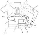
チョッキとして身につけるように構成された装着型除細動器31を装着している患者1が、図1に示されている。装着型除細動器31は、配線3により制御装置2に接続された検知電極4を含む。また、処置電極5が制御装置2に接続されている。制御装置2は、少なくとも1つの応答ボタン6を含む。応答ボタン6は、ボタン6を押す人の身体内に独特のマーカー信号11を送るように構成されている。好ましくは、マーカー信号11は、ボタン6を押す人の全身に亘って送られる。 A patient 1 wearing a
マーカー信号11は、アナログまたはデジタルのいずれでもよいが、応答ボタン6を押す人(好ましくは患者1であろう)に安全な電気特性でなければならない。好ましくは、マーカー信号11は、患者1に悪影響を与えないような、電子的に発生する振幅の小さな信号である。マーカー信号11は、患者1、または、患者1が装着した装着型除細動器31のいずれに対しても独特な記号化情報を含むことができる。 The
検知電極4は、患者1の心臓ECG12、または、その他の生体測定信号と共に、マーカー信号11を検出するように構成されている。制御装置2は、マーカー信号11と、該マーカー信号11を受けるように構成された1つ以上のセンサ4からの入力とを受けて、これらを解読するように構成されている。また、センサ4は、ECG信号またはその他の生体測定信号を検知するように構成してもよい。 The
制御装置2は、マーカー信号11が患者1に送られていることを確認するように構成されている。留意すべきは、マーカー信号11の確認により、応答ボタン6を作動するかも知れないいかなる人も、その人が患者1でない限り、装着型除細動器による処置の実行を阻止できないことを、制御装置2に保証させ得ることである。 The
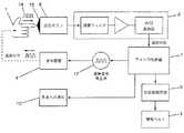
制御装置2に使用できる回路の、現時点で好ましい実施例が、図2に示されている。現時点で好ましい、回路の実施例は、図1に示す実施例の装着型除細動器に用いることができる。回路は、応答ボタン6に接続するマーカー信号発生器16を含む。マイクロ制御装置7が、マーカー信号発生器16、信号処理回路8、除細動器処理回路9、および患者通知回路10に接続している。応答ボタン6は生体認証機能を有する変換器17またはその他の変換器を含むことができ、これらの変換器は、マーカー信号発生器16により発生するマーカー信号11をボタン6を押す人の身体内に発信するように構成されている。 A presently preferred embodiment of a circuit that can be used in the
信号処理回路8は、変換器17により送信されたマーカー信号11を患者1の身体内に受信するように構成されている。マーカー信号11が患者1の身体から受信されない場合、マイクロ制御装置7は、処置電極5からの処置が患者1に提供されるように構成されている。信号処理回路8が生体認証機能を有する変換器17により送信されるマーカー信号11を受信する場合、マイクロ制御装置7は、これに記憶されたすなわちマイクロ制御装置7に作動可能に接続されるか、または、除細動器処理回路9内にプログラム化された、処置アルゴリズムまたはプログラムを処理するように構成されている。 The
処置アルゴリズムは、検知された患者1の状態が処置の必要性を示唆していること、応答ボタン6が駆動されたこと、およびマーカー信号11が受信されたことを確認して、応答ボタン6を駆動している人が患者1であることを確認するよう、制御装置2に要求することができる。患者1が応答ボタン6またはその他の作動装置を駆動しない場合、除細動器処理回路9は、処置電極5を作動させて患者1に処置を提供するように構成されている。患者1が応答ボタン6を作動する場合、応答ボタン6を作動するためには患者1は意識があるに違いないので、処置電極5が患者1に処置を行わないように、除細動器処理回路9またはマイクロ制御装置7は構成されている。 The treatment algorithm confirms that the sensed condition of the patient 1 indicates the need for treatment, that the
患者1を対象とする警報、指示または他のプロンプトに応答して患者でない者(以下「非患者」ということがある)が応答ボタン6を押す場合、制御装置2は、可聴出力、視認可能な出力またはその双方として、患者または通りかかった人に伝える追加の指示を送信するように構成されていてもよい。例えば、非患者が不当に応答ボタン6を押すならば、間もなく処置が患者に行われると、あるいは、非患者が応答ボタン6を押してはならず、非患者が患者1から離れて患者1に手出しをしてはならないと、非患者に知らせる指示が非患者に向けられたものであることを確証するように、制御装置2は構成されていてもよい。勿論、制御装置2は、また、その他の指示またはプロンプトを非患者、患者または双方に送信するように構成されていてもよい。 When a non-patient (hereinafter sometimes referred to as a “non-patient”) presses the
また、マイクロ制御装置7は、聴き取れる指示、視認可能な指示、または聴取り可能および視認可能な指示の双方の組合せを患者1または患者1の近くにいる他の者に提供するように、構成されていてもよい。マイクロ制御装置7は、制御装置2のハウジング上にまたはその中に配置された、あるいは患者1が装着するかまたは制御装置2に接続する別の器具に配置された、音声スピーカーまたは表示部に接続することができる。指示またはプロンプトが患者1に向けられるように、制御装置2を構成することができる。例えばLCD表示部等の表示部または制御装置2に接続する他の表示部に、例えば視認可能な指示を表示してもよい。また、スピーカーまたは他の聴取り可能な出力装置によって伝達される出力のように、指示を患者1に聴取り可能に与えてもよい。
留意すべきは、代替の実施形態では、機械的な作用または機能性を持たない応答ボタン6を含むことができる。例えば、代替の一実施形態では、制御装置のハウジングに取り付けられる作動装置、または制御装置2のハウジングと一体化された作動装置を含んでもよい。例えば、患者の意識がしっかりしていて処置の必要がないことの確認を患者に求める際に用いられる、警報または他のプロンプトに応答するために、患者が指または患者のその他の身体部分をどこの箇所に置くのか分かるように、制御装置のハウジングの一部に、当該部分と一体化した生体認証機能を有する変換器17の位置を識別する、しるし(indicia)を含んでいてもよい。 It should be noted that alternative embodiments may include a
減衰信号14を利用して、患者1がプロンプトまたは指示に応答していることを確定し、患者は意識があって処置の必要がないことを確認するように、装着型除細動器を構成することもできる。かかる装着型除細動器の一実施例が図3に示されていて、減衰信号14を利用する装着型除細動器41を示す。目下のところ好ましい装着型除細動器41の第二実施例のプロセシングを示すブロック図が、図4に示されている。1つ以上の処置電極5すなわち処置用電極が、独特の減衰マーカー信号14を患者1の身体内に発信するように配置されている。除細動器41の1つ以上のセンサ4が、減衰信号14を検知するように配置されている。減衰信号14は、1つ以上のセンサ4がまた例えばECG信号および他の信号等の他の生体認証機能を有する信号を検知できる、電気特性を有することが好ましい。制御装置2は減衰信号14の存在を検出するように構成されている。 The wearable defibrillator is configured to utilize the
また、制御装置2は、センサ4が身体から脱落したかどうかを検出するように構成してもよい。例えば、制御装置2は、減衰マーカー信号14をセンサ4の1つが検出しないが、その他のセンサ4が検出する場合、センサ4が患者1の身体から離脱したと確定するように構成されてもよい。かかる状況が存在することを制御装置2が確定した場合、患者1に1つ以上のプロンプトまたは指示を出して、取り外されたセンサ4を再び付着させるように、制御装置を構成してもよい。このようなプロンプトまたは指示は、制御装置2に接続されたディスプレイ、または、制御装置2に接続されたスピーカーに与えることができる。 Moreover, you may comprise the
制御装置2は、減衰信号発生器17、センサ4、患者通知回路10、除細動器回路9、および信号処理回路8に接続するマイクロ制御装置7を含む。装着型除細動器の幾つかの実施形態において、信号処理回路8、患者通知回路10、およびマイクロ制御装置7は、制御装置2のハウジング内に配置することができる。
減衰信号発生器17はセンサ4に接続している。他の実施形態において、減衰信号発生器17は、患者1が装着する分離した素子、例えば処置電極5に接続していてもよい。The
The
応答ボタン6は、生体認証機能を有する検出器18、または応答ボタンに接触する人の身体から減衰信号14を受信するように構成されたセンサを含む。信号処理回路8は、減衰信号14が生体認証機能を有する検出器18から受信されたかどうかを確定するように構成されている。 The
制御装置2は、応答ボタン6が駆動されたかどうか、そうであれば、減衰信号14が生体認証機能を有する検出器18から受信されていたかどうかを確定するように構成されている。減衰信号14が受信され、かつ、応答ボタン6が作動されていたならば、制御装置2は患者1が応答ボタン6を作動していたと確定するように構成されている。留意すべきは、かかる確定は、制御装置2に接続された通知装置(例えば、モニターまたはスピーカー等)によって、表示または提示されるプロンプトまたは指示に、患者1が応答したことの確認に用いることができる。 The
装着型除細動器51の第三実施例が図5,6,7に示されている。装着型除細動器51の応答ボタン6は、除細動器を装着している患者1のECG信号12を検知するように構成されたECG検出器19を含む。ECG検出器19の少なくとも一部が、応答ボタン6の外表面を越えて広がる、すなわち、応答ボタン6の外表面に取り付けられ得るように、さもなければ、応答ボタン6に連結されるように、ECG検出器19を応答ボタン6に取り付けることができる。好ましくは、ECG検出器19は、除細動器51に取り付けられるECGセンサ4と同じデザインのECG電極からなる。 A third embodiment of a
除細動器51の制御装置2は、ECG検出器19で受信されたあらゆるECG信号20を、患者1が装着したECGセンサ4で受信されたECG信号20,21と相関させることによって、患者1が応答ボタン6を作動していることを確認するように構成されてもよい。種々の方法で、ECG検出器19で受信されたECG信号を患者1が装着したECGセンサ4で受信されたECG信号と比較するように、制御装置2を構成することができる。例えば、形態比較、変化率の比較、R波同期またはこれらの任意の組合せを利用して、ECG信号20,21を比較し、ECG信号20,21がECG検出器19で受信されたかどうかを確定して、応答ボタン6を作動させる人が患者1であることを確認するように、制御装置2を構成してもよい。 The
留意すべきは、患者でない者が応答ボタン6を作動するならば、制御装置2によって相関するECG信号が検出されてはならない。図7に示すように、非患者が応答ボタン6を作動する場合、ECG検出器19で受信されたECG信号は、センサ4で受信されつつある患者のECG信号と一致しないECG信号であろう。同様に留意すべきは、患者1でない者が除細動器51の電気回路網と基底基準が共通していないならば、制御装置2が破損した信号を受信するかまたは全く信号を受信しないであろう。信号処理回路8またはマイクロ制御装置7は、ECG検出器19から受信された信号が、センサ4から受信された信号と一致しないことを認識するように構成されている。制御装置2は、その決定が患者1でない者によってなされた、応答ボタン6のいかなる作動も無視するように構成可能である。また、応答ボタンを作動させた非患者にプロンプトまたは指示を与えて、応答ボタンを作動させる者が患者1でないことを確認するために、非患者がプロンプトに応答してはならない(即ち、更に入力を要求してはならない)ことを非患者に知らせるように、あるいは、患者1に対して間もなく処置が行われる予定で、従って非患者は患者1から離れなければならないことを非患者に知らせるように、制御装置2を構成してもよい。 Note that if a non-patient activates the
図8、図9に示す装着型除細動器の別の実施例では、患者1が応答ボタン6を作動させていること、あるいは、その他の応答機構を作動させていることを、応答ボタンを作動させる者または物体の電気容量値を検出することによって、確認するように構成された装着型除細動器61を図示している。患者1、または、別の者が応答機構を作動させたかどうかの確認に、電気容量値を用いることができる。例えば、測定された電気容量値を制御装置に記憶されている患者に関する数値、または、それらの範囲と比較して、患者が応答機構を作動させたことを確認することができる。記憶された電気容量値、または、それらの範囲は、除細動器の起動手順中に制御装置2に記憶されてもよく、あるいは、前記電気容量値または範囲を、患者1が除細動器を最初に使用する時に制御装置2により記憶および保存され、新たな数値またはそれらの範囲を制御装置2に保存して古い数値、または、それらの範囲を置換するまで、制御装置2により再利用してもよい。 In another embodiment of the wearable defibrillator shown in FIGS. 8 and 9, the response button is used to indicate that the patient 1 is operating the
装着型除細動器61の制御装置2は、電気容量検出器22または他の電気容量センサを有する応答ボタン6を含む。好ましくは、電気容量検出器22は電気容量型電極からなる。電気容量検出器22は、応答ボタン6と電気容量検出器22との患者特有の物理的相互作用に起因して、変動する電気容量23の変化を検出するように構成された、接触センサ15または他の電気回路網に接続されている。図9に示すように、電気容量検出器22で検知される電気容量値を、制御装置2すなわち制御装置2に接続するメモリーに記憶された電気容量値またはそれらの範囲と比較することによって、応答ボタン6が患者1により作動されたことを確定するように、制御装置2を構成することができる。電気容量値が記憶された数値の範囲内にないかまたは記憶された数値でないならば、制御装置2は患者1が応答ボタン6を作動しなかったと確定するように構成されている。患者1が応答ボタン6を作動しなかったと確定されるならば、制御装置2は、応答ボタン6の作動を無視するように構成されてもよく、また、応答ボタン6を作動したかも知れない非患者に1つ以上のプロンプトまたは指示を出すように構成されてもよい。 The
また、患者が装着型除細動器に入力を行っていることの確認に装飾品を使用することができる。例えば、図10に示す装着型除細動器71の実施例では、識別マーカー26を除細動器の制御装置2に送信する1つ以上の装飾品を含む。装飾品は、指輪24、ブレスレット25、ネックレス、飾り紐、イヤリング、バッジ、名札、ユーザが身に着けることがあるその他のあらゆる装飾品、またはこれらの任意の組合せであってもよい。 Also, ornaments can be used to confirm that the patient is inputting into the wearable defibrillator. For example, the wearable defibrillator 71 embodiment shown in FIG. 10 includes one or more ornaments that transmit the
制御装置2は、1つ以上の装飾品により送信される識別マーカーを受信するように構成された、1つ以上の受信器または他の検出器を含むことができる。制御装置2は、また、装飾品が制御装置2のハウジングまたは制御装置2に接続するモニターもしくは他の表示部に近接する時を測定するように、構成されてもよい。例えば、1つ以上の装飾品を検出するように構成された磁気近接検出器27または他の近接センサを、制御装置2に設けてもまたは接続してもよい。 The
患者が例えば応答ボタン6等の応答機構を作動していることを確認するために、装飾品の存在を利用するように制御装置2を構成することができる。制御装置2は、また、制御装置2により管理または制御される処置シーケンス中に、全ての応答機構の作動が患者によってなされることを確認するように構成されてもよい。例えば、相関する識別装飾品が検知されない、即ち、装飾品が制御装置2または受信器から所定の距離の範囲内にあると検知されないならば、応答機構の作動を無視するか、あるいは、制御装置2に接続する表示部またはスピーカーを介して、プロンプト、警報、または指示を更に患者に送信するように、制御装置2を構成することができる。 The
例えば1つ以上の応答ボタン6等の応答機構の配設位置を、患者以外の者による偶発的な起動または応答を回避する大きさにして、上記応答機構を配置してもよい。例えば、応答機構は、制御装置2のハウジング上に配設される1つ以上のボタンを含んでいてもよく、隠れたすなわち見えない場所に配設される。このような隠れた場所の一例として、制御装置のハウジングの凹部であってもよい。上記隠れた場所の別の例としては、制御装置2のハウジングに移動可能に接続するラッチまたはカバーの下に、または制御装置2に接続するに表示部の下に、1つ以上の応答ボタン6を位置させてもよい。更に別の例として、応答機構は、制御装置2にワイヤレスで接続された1つ以上の作動装置を有する装置であってもよい。かかる装置は、患者がまとう1枚の衣類のポケット内にあっても、あるいは、典型的な通りがかりの人が見えそうにないまたは見い出しそうにない別の場所に位置してもよい。 For example, the response mechanism such as one or
留意すべきは、複数のボタン6、応答スイッチ、または他の応答機構は、制御装置2に接続してもよい。応答機構の作動に2以上のボタンの同時駆動が必要となるように、2以上の応答ボタンを使用することが好ましい。かかる構成は誤検出を低減させることができる。 It should be noted that a plurality of
勿論、応答機構の作動は、また、特定の順序で1つ以上の応答ボタンを作動することを含むことができる。例えば、患者が異なったボタンを特定の順序で押すか、あるいは、1つ以上の応答スイッチまたは他のボタンを異なった位置に移動させると、応答機構の作動が生じるように制御装置2または応答機構を構成してもよい。例えば、スイッチを有する応答機構を含む実施形態の場合では、第一位置から第二位置にその後所定の時間間隔内に第一位置に戻るスイッチの移動が、応答機構を作動させるのに必要であるように、応答機構を構成することができるであろう。 Of course, activation of the response mechanism can also include activating one or more response buttons in a particular order. For example, the
留意すべきは、非患者による偶発的な起動または応答を回避するために、1つ以上のセンサを更に使用してもよい。このような追加のセンサとしては、例えば、指紋、声、または顔相認識センサ等の生体認証機能を有するセンサを挙げることができる。制御装置2に記憶されるかさもなければ制御装置2に接続するメモリーに記憶された、患者のデータと相関する追加のセンサから入力を要求して、患者が応答機構を作動しているかさもなければ制御装置2に入力が行われていることを確認するように、制御装置2を構成することができる。 It should be noted that one or more sensors may further be used to avoid accidental activation or response by non-patients. Examples of such an additional sensor include a sensor having a biometric authentication function such as a fingerprint, a voice, or a facial recognition sensor. Whether the patient is activating the response mechanism, requesting input from additional sensors correlated with patient data stored in the
勿論また、他の確認方法を用いて、患者が制御装置2に入力を行いつつあると確認する入力を更に行うように、制御装置2を構成することができる。また、例えば、制御装置2への電流路または制御装置2に接続する表示装置への電流路を含むフィードバック・ループを用いて、患者が制御装置2に入力を行いつつあることを確認してもよい。
また、1つ以上の追加のセンサは、動作、位置、または酸素濃度計の検出器を含むことができ、検出器は、患者の身体の別の領域に配置されると共に制御装置2に接続する。患者1の状態を確定する際に制御装置2を支援するために、上記センサから入力が得られるように、制御装置2を構成することができるであろう。Of course, the
Also, the one or more additional sensors can include motion, position, or oximeter detectors that are located in separate areas of the patient's body and connected to the
また、装着型除細動器の実施形態では、患者1からコードまたはパスワードを受信するように構成された制御装置2を含むことができる。1つ以上のボタン、キー・パッド、または制御装置2に接続もしくは配置された他のデータ入力装置の使用により、パスワードまたはコードを制御装置2に提供することができる。患者1が意識のないとき、患者以外の誰かが何気なしに応答を発することを防止するために、一連の警報または他のプロンプトもしくは指示を出している間は、何時でも、パスワードまたはコードの申告を要求するように、制御装置2を構成することができるであろう。勿論また、かかるコードは、1つ以上の応答ボタン、1つ以上の応答スイッチ、または他の応答作動装置を所定の順序で押釦することを含むことができるであろう。 Also, the wearable defibrillator embodiment can include a
勿論また、制御装置2は応答機構が適切に作動していることを確認するように構成されているので、破壊または損傷した応答機構が原因で生じるエラーを回避または軽減することができる。一実施形態において、日常的に適切な機能性について応答機構を検査するか、あるいは応答機構をモニターして、応答機構の故障を予知するように、制御装置2を構成することができる。例えば、除細動器が起動する時にはいつも応答試験を行うように、制御装置2を構成することができる。制御装置2が、応答機構から入力信号を受信しないか、あるいは応答機構の試験中に応答機構のいかなる作動をも認識しない場合、応答機構は破壊しているかまたは修理の必要があることを患者1に知らせる、聴取り可能または視認可能な1つ以上のプロンプトを患者1に出すように、制御装置2を構成してもよい。また、処置を阻止すべく、電源を制御装置2から取り外す必要があることを患者1に知らせることが可能であれば、代替の応答性試験方法を用いるように制御装置2を構成してもよい。また、応答機構が適切に機能していることを制御装置2が確定した後に、除細動器を停止させるように制御装置2を構成してもよい。 Of course, since the
応答機構の稼働状況をモニターして応答機構の故障を予知するように制御装置2が構成されている場合、応答機構の将来の故障を予測するように構成された予測アルゴリズムを処理するように、制御装置2を構成してもよい。故障が予知されると、患者1に警報を発するように、除細動器を無効にするように、または両方に制御装置2を構成することができる。 When the
留意すべきは、現時点での好ましい以上の実施形態を種々変更することができる。例えば、装着型除細動器の実施形態では、ハーネス、ベルト、チョッキ、または他の装着可能な器具として装着される大きさに、除細動器を構成することができる。別の例として、応答機構は、1つ以上の応答ボタン、応答スイッチ、他の応答作動装置、またはこれらの任意の組合せを含むことができる。更に別の例として、装着型除細動器の制御装置2は、1つ以上の直接的もしくは間接的な無線接続、直接的もしくは間接的な有線接続、またはこれらの任意の組合せにより、装着型除細動器の様々な構成部材に接続してもよい。更に他の例として、処置電極は、例えば米国特許第5078134号明細書に開示されているパルス電極等の、当業者にとって公知の種々のタイプの処置電極を含むことができる。 It should be noted that various changes can be made to the presently preferred embodiment. For example, in a wearable defibrillator embodiment, the defibrillator can be configured to be sized to be worn as a harness, belt, waistcoat, or other wearable device. As another example, the response mechanism can include one or more response buttons, response switches, other response actuators, or any combination thereof. As yet another example, the
装着型除細動器の現時点での好ましい特定の実施形態、およびこれらを実施する方法の特定の実施形態を示すと共に説明してきたが、留意すべきは、本発明はこれらに限定されるものではなく、特許請求の範囲の定義範囲内で本発明を種々の別の方法で具体化し、実施することができるだろう。 While presently preferred specific embodiments of wearable defibrillators and specific embodiments of methods for performing them have been shown and described, it should be noted that the invention is not limited thereto. Rather, the invention may be embodied and embodied in various other ways within the scope of the following claims.
1 患者
2 制御装置
3 配線
4 検知電極、センサ
5 処置電極
6 応答ボタン
7 マイクロ制御装置
8 信号処理回路
9 除細動器処理回路
10 患者通知回路
11 マーカー信号
12 心臓ECG
14 減衰信号
15 接触センサ
16 マーカー信号発生器
17 変換器
18 検出器
19 ECG検出器
20 ECG信号
21 ECG信号
22 電気容量検出器
24 指輪
25 ブレスレット
26 識別マーカー
31 装着型除細動器
41 装着型除細動器
51 装着型除細動器
61 装着型除細動器DESCRIPTION OF SYMBOLS 1
DESCRIPTION OF
Claims (8)
Translated fromJapanese前記患者の医学的状態を前記医療器具のセンサを使用して前記医療器具によって検知する段階と、
前記医療器具において、検知した前記医学的状態に基づいて前記患者が治療を必要としているかどうか決定する段階と、
前記患者が治療を必要としているとの決定に応答して、少なくとも1つの応答機構を作動するように前記患者に向けられたプロンプトを前記医療器具から発する段階と、
前記医療器具において、前記少なくとも1つの応答機構の作動中に受けた少なくとも1つの信号を検出する段階であって、それにより前記医療器具を装着している前記患者が前記少なくとも1つの応答機構を作動させたことを検証する段階と
を含む方法。Ina methodfor controlling the operation ofa medical deviceattached to a patient ,
Detecting themedical condition of the patient with the medical deviceusing a sensorof the medical device ;
Determining in the medical device whether the patient needs treatment based on the sensed medical condition;
In response to a determination that the patient needs treatment, issuing a prompt from the medical device directed to the patient to activate at least one response mechanism;
In the medical instrument, said comprising the steps ofdetect at least one signal received during operation of the at least one response mechanism, whereby the patient wearing the medical instrument said at least one response mechanism Verifying that it has been activated.
前記医療器具を装着している前記患者に治療がまもなく提供されること、
前記少なくとも1つの応答機構を作動させないこと、および
前記医療器具を装着している前記患者に触れないこと
の少なくとも1つを前記人に知らせる指示を含む請求項5に記載された方法。The at least one of the visible instruction and the audible instruction is:
Treatment is soon to be provided to the patient wearing the medical device;
6. The method of claim 5, comprising instructions to inform the person at least one of not activating the at least one response mechanism and not touching the patient wearing the medical device.
Applications Claiming Priority (4)
| Application Number | Priority Date | Filing Date | Title |
|---|---|---|---|
| US93355007P | 2007-06-07 | 2007-06-07 | |
| US60/933,550 | 2007-06-07 | ||
| US12/150,720 | 2008-04-30 | ||
| US12/150,720US8271082B2 (en) | 2007-06-07 | 2008-04-30 | Medical device configured to test for user responsiveness |
Related Parent Applications (1)
| Application Number | Title | Priority Date | Filing Date |
|---|---|---|---|
| JP2008148804ADivisionJP5492388B2 (en) | 2007-06-07 | 2008-06-06 | A medical device configured to verify user responsiveness |
Related Child Applications (1)
| Application Number | Title | Priority Date | Filing Date |
|---|---|---|---|
| JP2015201267ADivisionJP6142442B2 (en) | 2007-06-07 | 2015-10-09 | A medical device configured to verify user responsiveness |
Publications (2)
| Publication Number | Publication Date |
|---|---|
| JP2014111162A JP2014111162A (en) | 2014-06-19 |
| JP5824540B2true JP5824540B2 (en) | 2015-11-25 |
Family
ID=40011399
Family Applications (3)
| Application Number | Title | Priority Date | Filing Date |
|---|---|---|---|
| JP2008148804AExpired - Fee RelatedJP5492388B2 (en) | 2007-06-07 | 2008-06-06 | A medical device configured to verify user responsiveness |
| JP2014014694AExpired - Fee RelatedJP5824540B2 (en) | 2007-06-07 | 2014-01-29 | A medical device configured to verify user responsiveness |
| JP2015201267AActiveJP6142442B2 (en) | 2007-06-07 | 2015-10-09 | A medical device configured to verify user responsiveness |
Family Applications Before (1)
| Application Number | Title | Priority Date | Filing Date |
|---|---|---|---|
| JP2008148804AExpired - Fee RelatedJP5492388B2 (en) | 2007-06-07 | 2008-06-06 | A medical device configured to verify user responsiveness |
Family Applications After (1)
| Application Number | Title | Priority Date | Filing Date |
|---|---|---|---|
| JP2015201267AActiveJP6142442B2 (en) | 2007-06-07 | 2015-10-09 | A medical device configured to verify user responsiveness |
Country Status (4)
| Country | Link |
|---|---|
| US (7) | US8271082B2 (en) |
| JP (3) | JP5492388B2 (en) |
| DE (1) | DE102008025709B4 (en) |
| FR (1) | FR2916982B1 (en) |
Families Citing this family (87)
| Publication number | Priority date | Publication date | Assignee | Title |
|---|---|---|---|---|
| US8369944B2 (en) | 2007-06-06 | 2013-02-05 | Zoll Medical Corporation | Wearable defibrillator with audio input/output |
| US8271082B2 (en) | 2007-06-07 | 2012-09-18 | Zoll Medical Corporation | Medical device configured to test for user responsiveness |
| US8140154B2 (en) | 2007-06-13 | 2012-03-20 | Zoll Medical Corporation | Wearable medical treatment device |
| US7974689B2 (en)* | 2007-06-13 | 2011-07-05 | Zoll Medical Corporation | Wearable medical treatment device with motion/position detection |
| US20100311482A1 (en)* | 2009-05-30 | 2010-12-09 | Lange Daniel H | Electro-Biometric Methods and Apparatus |
| US8706215B2 (en) | 2010-05-18 | 2014-04-22 | Zoll Medical Corporation | Wearable ambulatory medical device with multiple sensing electrodes |
| US9008801B2 (en) | 2010-05-18 | 2015-04-14 | Zoll Medical Corporation | Wearable therapeutic device |
| US10493289B2 (en) | 2010-07-09 | 2019-12-03 | Zoll Medical Corporation | System and method for conserving power in a medical device |
| US9937355B2 (en)* | 2010-11-08 | 2018-04-10 | Zoll Medical Corporation | Remote medical device alarm |
| JP5963767B2 (en) | 2010-12-09 | 2016-08-03 | ゾール メディカル コーポレイションZOLL Medical Corporation | Electrode assembly |
| JP5988991B2 (en) | 2010-12-10 | 2016-09-07 | ゾール メディカル コーポレイションZOLL Medical Corporation | Wearable treatment device |
| US9427564B2 (en) | 2010-12-16 | 2016-08-30 | Zoll Medical Corporation | Water resistant wearable medical device |
| JP6096125B2 (en)* | 2011-01-27 | 2017-03-15 | コーニンクレッカ フィリップス エヌ ヴェKoninklijke Philips N.V. | Defibrillator paddle with lit shock button |
| US9135398B2 (en) | 2011-03-25 | 2015-09-15 | Zoll Medical Corporation | System and method for adapting alarms in a wearable medical device |
| WO2012135062A1 (en) | 2011-03-25 | 2012-10-04 | Zoll Medical Corporation | Selection of optimal channel for rate determination |
| WO2012135028A1 (en) | 2011-03-25 | 2012-10-04 | Zoll Medical Corporation | Method of detecting signal clipping in a wearable ambulatory medical device |
| US9684767B2 (en) | 2011-03-25 | 2017-06-20 | Zoll Medical Corporation | System and method for adapting alarms in a wearable medical device |
| JP2014516654A (en) | 2011-05-02 | 2014-07-17 | ゾール メディカル コーポレイション | Patient-worn energy supply device and technology for adjusting its size |
| CN103764222B (en) | 2011-09-01 | 2016-02-10 | 佐尔医药公司 | Wearable monitoring and treatment equipment |
| EP3610919A1 (en) | 2012-03-02 | 2020-02-19 | Zoll Medical Corporation | A system comprising a wearable therapeutic device |
| US10328266B2 (en) | 2012-05-31 | 2019-06-25 | Zoll Medical Corporation | External pacing device with discomfort management |
| CN104428034A (en) | 2012-05-31 | 2015-03-18 | 佐尔医药公司 | Systems and methods for detecting health disorders |
| CN104870050A (en) | 2012-05-31 | 2015-08-26 | 佐尔医药公司 | Medical monitoring and treatment device with external pacing |
| US11097107B2 (en) | 2012-05-31 | 2021-08-24 | Zoll Medical Corporation | External pacing device with discomfort management |
| US20140025131A1 (en)* | 2012-07-20 | 2014-01-23 | Physio-Control, Inc. | Wearable defibrillator with voice prompts and voice recognition |
| FR2994098B1 (en)* | 2012-08-06 | 2020-02-21 | Pierre Henri Cadet | COMMUNICATING DEFIBRILLATOR DEVICE |
| US9999393B2 (en) | 2013-01-29 | 2018-06-19 | Zoll Medical Corporation | Delivery of electrode gel using CPR puck |
| US9443521B1 (en) | 2013-02-14 | 2016-09-13 | Sociometric Solutions, Inc. | Methods for automatically analyzing conversational turn-taking patterns |
| US10049336B2 (en) | 2013-02-14 | 2018-08-14 | Sociometric Solutions, Inc. | Social sensing and behavioral analysis system |
| US8880196B2 (en) | 2013-03-04 | 2014-11-04 | Zoll Medical Corporation | Flexible therapy electrode |
| US10016613B2 (en) | 2013-04-02 | 2018-07-10 | West Affum Holdings Corp. | Wearable cardiac defibrillator system long-term monitoring alternating patient parameters other than ECG |
| US9827431B2 (en) | 2013-04-02 | 2017-11-28 | West Affum Holdings Corp. | Wearable defibrillator with no long-term ECG monitoring |
| SG11201509487WA (en)* | 2013-06-07 | 2015-12-30 | Sociometric Solutions Inc | Social sensing and behavioral analysis system |
| WO2014210510A1 (en) | 2013-06-28 | 2014-12-31 | Zoll Medical Corporation | Systems and methods of delivering therapy using an ambulatory medical device |
| JP2016531663A (en) | 2013-08-01 | 2016-10-13 | ゾール メディカル コーポレイションZOLL Medical Corporation | System and method for utilizing an identification device in a wearable medical treatment device |
| CN205796253U9 (en)* | 2013-08-01 | 2022-10-25 | 卓尔医疗公司 | Medical treatment device and wearable defibrillator |
| IN2015DN02541A (en)* | 2013-10-18 | 2015-09-11 | Healthwatch Ltd | |
| WO2015123198A1 (en) | 2014-02-12 | 2015-08-20 | Zoll Medical Corporation | System and method for adapting alarms in a wearable medical device |
| CN106456984B (en) | 2014-02-24 | 2019-07-09 | 元素科学公司 | External defibrillator |
| CN107193382B (en)* | 2014-02-24 | 2020-08-07 | 索尼公司 | Smart wearable devices and methods for automatically utilizing sensors to configure capabilities |
| US9352166B2 (en)* | 2014-03-19 | 2016-05-31 | West Affum Holdings Corp. | Wearable cardiac defibrillator system sounding to bystanders in patient's own voice |
| US20180116537A1 (en) | 2014-07-07 | 2018-05-03 | Zoll Medical Corporation | System and Method for Distinguishing a Cardiac Event From Noise in an Electrocardiogram (ECG) Signal |
| US9724008B2 (en) | 2014-07-07 | 2017-08-08 | Zoll Medical Corporation | System and method for distinguishing a cardiac event from noise in an electrocardiogram (ECG) signal |
| EP3892198B1 (en) | 2014-11-14 | 2024-03-06 | ZOLL Medical Corporation | Medical premonitory event estimation |
| US9902028B2 (en) | 2014-11-20 | 2018-02-27 | Zoll Medical Corporation | External case for a wearable medical device |
| WO2016085433A1 (en)* | 2014-11-25 | 2016-06-02 | Orhan Umut | Automated electroshock wristband |
| US10201711B2 (en) | 2014-12-18 | 2019-02-12 | Zoll Medical Corporation | Pacing device with acoustic sensor |
| US10201714B2 (en)* | 2014-12-30 | 2019-02-12 | Koninklijke Philips N.V. | Advanced warning indicator for emergency medical devices |
| EP4218551A3 (en) | 2015-02-27 | 2023-08-09 | Zoll Medical Corporation | Downloading and booting method and system for a wearable medical device |
| US10321877B2 (en) | 2015-03-18 | 2019-06-18 | Zoll Medical Corporation | Medical device with acoustic sensor |
| WO2016160369A1 (en) | 2015-03-20 | 2016-10-06 | Zoll Medical Corporation | Systems for self-testing an ambulatory medical device |
| US10835449B2 (en) | 2015-03-30 | 2020-11-17 | Zoll Medical Corporation | Modular components for medical devices |
| US10127357B2 (en) | 2015-05-18 | 2018-11-13 | Zoll Medical Corporation | Mobile monitoring and patient management system |
| US10578677B2 (en) | 2015-06-30 | 2020-03-03 | Zoll Medical Corporation | Systems and methods for monitoring battery life status |
| US9839356B2 (en) | 2015-07-07 | 2017-12-12 | Zoll Medical Corporation | Systems and methods for communicating data |
| EP4183446A1 (en) | 2015-08-26 | 2023-05-24 | Element Science, Inc. | Wearable defibrillation devices |
| US10252070B2 (en) | 2015-09-08 | 2019-04-09 | Zoll Medical Corporation | Secure limited components for use with medical devices |
| US11364389B2 (en) | 2015-10-01 | 2022-06-21 | Zoll Medical Corporation | Training modules for an external medical device |
| PL3693057T3 (en) | 2015-11-23 | 2023-02-20 | Zoll Medical Corporation | Garments for wearable medical devices |
| US11116426B2 (en) | 2015-12-09 | 2021-09-14 | Zoll Medical Corporation | Device administered tests and adaptive interactions |
| US11064952B2 (en) | 2015-12-30 | 2021-07-20 | Zoll Medical Corporation | External medical device that identifies a response activity |
| US11709747B2 (en) | 2016-01-08 | 2023-07-25 | Zoll Medical Corporation | Patient assurance system and method |
| US10561852B2 (en)* | 2016-02-26 | 2020-02-18 | Zoll Medical Corporation | Systems and methods for providing rapid medical care |
| US11617538B2 (en) | 2016-03-14 | 2023-04-04 | Zoll Medical Corporation | Proximity based processing systems and methods |
| US10674911B2 (en) | 2016-03-30 | 2020-06-09 | Zoll Medical Corporation | Systems and methods of integrating ambulatory medical devices |
| US10426342B2 (en) | 2016-03-31 | 2019-10-01 | Zoll Medical Corporation | Remote access for ambulatory medical device |
| US11508474B2 (en) | 2016-03-31 | 2022-11-22 | Zoll Medical Corporation | Event reconstruction for a medical device |
| US10149981B2 (en)* | 2016-05-03 | 2018-12-11 | Cardiac Pacemakers, Inc. | Authentication of shock therapy deferral |
| US10632301B2 (en) | 2016-09-30 | 2020-04-28 | Zoll Medical Corporation | Medical device connector for coupling electrodes |
| US11672484B2 (en) | 2016-12-16 | 2023-06-13 | Zoll Medical Corporation | Electrode falloff detection |
| US11213691B2 (en) | 2017-02-27 | 2022-01-04 | Zoll Medical Corporation | Ambulatory medical device interaction |
| US11009870B2 (en) | 2017-06-06 | 2021-05-18 | Zoll Medical Corporation | Vehicle compatible ambulatory defibrillator |
| WO2019075035A1 (en) | 2017-10-12 | 2019-04-18 | Zoll Medical Corporation | System and method for distinguishing a cardiac event from noise in an electrocardiogram (ecg) signal |
| US10646707B2 (en) | 2017-11-30 | 2020-05-12 | Zoll Medical Corporation | Medical devices with rapid sensor recovery |
| US10960213B2 (en) | 2018-03-12 | 2021-03-30 | Zoll Medical Corporation | Verification of cardiac arrhythmia prior to therapeutic stimulation |
| US10602945B2 (en) | 2018-03-13 | 2020-03-31 | Zoll Medical Corporation | Telemetry of wearable medical device information to secondary medical device or system |
| WO2019178524A1 (en) | 2018-03-16 | 2019-09-19 | Zoll Medical Corporation | Monitoring physiological status based on bio-vibrational and radio frequency data analysis |
| US11942222B2 (en) | 2018-06-18 | 2024-03-26 | Zoll Medical Corporation | Medical device for estimating risk of patient deterioration |
| US10918877B2 (en) | 2018-09-28 | 2021-02-16 | Zoll Medical Corporation | Battery lock for ambulatory medical device |
| US11568984B2 (en) | 2018-09-28 | 2023-01-31 | Zoll Medical Corporation | Systems and methods for device inventory management and tracking |
| WO2020069308A1 (en) | 2018-09-28 | 2020-04-02 | Zoll Medical Corporation | Adhesively coupled wearable medical device |
| CA3112450A1 (en) | 2018-10-10 | 2020-04-16 | Element Science, Inc. | Wearable medical device with disposable and reusable components |
| US11642539B2 (en)* | 2018-12-21 | 2023-05-09 | Zoll Medical Corporation | Response mechanisms |
| EP3902598B1 (en) | 2018-12-28 | 2024-12-04 | ZOLL Medical Corporation | Wearable medical device response mechanisms |
| CN112642061A (en) | 2019-10-09 | 2021-04-13 | Zoll医疗公司 | Modular electrotherapy device |
| US12403322B2 (en) | 2021-02-08 | 2025-09-02 | Zoll Medical Corporation | Modular ingress protected electrode system for a wearable defibrillator |
| MX2021007385A (en)* | 2021-06-17 | 2021-09-23 | Meliton Angeles Martinez | Auxiliary testing device for multipolar electrical instruments. |
Family Cites Families (175)
| Publication number | Priority date | Publication date | Assignee | Title |
|---|---|---|---|---|
| JPS5115450A (en) | 1974-07-29 | 1976-02-06 | Ritsuo Hasumi | HIKARIDENSOFUAIBAANO HANSHAFUIRUTA |
| DE2644236C3 (en) | 1976-09-30 | 1981-04-02 | Siemens AG, 1000 Berlin und 8000 München | Electrode for taking physiological signals |
| US4094310A (en)* | 1976-10-04 | 1978-06-13 | American Optical Corporation | Apparatus for enhanced display of physiological waveforms and for defibrillation |
| US4632122A (en) | 1985-04-24 | 1986-12-30 | Johansson Nils E | Method and apparatus for conducting brain function diagnostic test |
| IT1208223B (en) | 1987-06-18 | 1989-06-12 | Sgs Microelettronica Spa | HIGH DYNAMIC APPLICATION STAGE WITH DISTORTION DETECTION. |
| US4869254A (en) | 1988-03-30 | 1989-09-26 | Nellcor Incorporated | Method and apparatus for calculating arterial oxygen saturation |
| US5078134A (en) | 1988-04-25 | 1992-01-07 | Lifecor, Inc. | Portable device for sensing cardiac function and automatically delivering electrical therapy |
| US4928690A (en)* | 1988-04-25 | 1990-05-29 | Lifecor, Inc. | Portable device for sensing cardiac function and automatically delivering electrical therapy |
| US5062834A (en) | 1989-02-24 | 1991-11-05 | Product Development (S.G.Z.) Ltd | Device for dispensing a liquid particularly useful for delivering medicaments at a predetermined rate |
| US4978926A (en) | 1989-12-21 | 1990-12-18 | Ford Motor Company | Audio limiter using voltage multiplexed feedback |
| JP2765602B2 (en) | 1991-10-30 | 1998-06-18 | 日本電気株式会社 | Auto drift cancellation circuit of ECG analyzer |
| US5353793A (en) | 1991-11-25 | 1994-10-11 | Oishi-Kogyo Company | Sensor apparatus |
| US5342404A (en)* | 1992-04-03 | 1994-08-30 | Intermedics, Inc. | Implantable medical interventional device |
| AU1796595A (en) | 1992-12-01 | 1995-07-13 | Siemens Aktiengesellschaft | Cardiac arrhythmia detection system for an implantable stimulation device |
| ITMI931761A1 (en)* | 1993-08-03 | 1995-02-03 | Healtech Sa | INFORMATION SUPPORT DEVICE THAT CAN BE ASSOCIATED WITH OUTPATIENT OR HOSPITAL PATIENTS FOR THEIR AUTOMATIC IDENTIFICATION AND |
| US5365932A (en) | 1993-09-02 | 1994-11-22 | Telectronics Pacing System, Inc. | Cardiac signal sensing device having sensitivity automatically controlled in response to metabolic demand |
| US5738102A (en)* | 1994-03-31 | 1998-04-14 | Lemelson; Jerome H. | Patient monitoring system |
| US5652570A (en) | 1994-05-19 | 1997-07-29 | Lepkofker; Robert | Individual location system |
| US5752976A (en) | 1995-06-23 | 1998-05-19 | Medtronic, Inc. | World wide patient location and data telemetry system for implantable medical devices |
| US5645571B1 (en) | 1995-08-01 | 1999-08-24 | Surviva Link Corp | Automated external defibrillator with lid activated self-test system |
| US5662689A (en) | 1995-09-08 | 1997-09-02 | Medtronic, Inc. | Method and apparatus for alleviating cardioversion shock pain |
| US6016445A (en)* | 1996-04-16 | 2000-01-18 | Cardiotronics | Method and apparatus for electrode and transthoracic impedance estimation |
| US5741306A (en) | 1996-05-23 | 1998-04-21 | Lifecor, Inc. | Patient-worn energy delivery apparatus |
| US6280461B1 (en) | 1996-05-23 | 2001-08-28 | Lifecor, Inc. | Patient-worn energy delivery apparatus |
| US6148233A (en)* | 1997-03-07 | 2000-11-14 | Cardiac Science, Inc. | Defibrillation system having segmented electrodes |
| US6169397B1 (en) | 1997-08-13 | 2001-01-02 | University Technology Corp. | Damped superconducting coil system having a multiturn, planar geometry superconducting coil and shunt resistors electrically connecting successive coil turns |
| US5944669A (en) | 1997-11-20 | 1999-08-31 | Lifecor, Inc. | Apparatus and method for sensing cardiac function |
| US5929601A (en) | 1997-12-22 | 1999-07-27 | Lifecor, Inc. | Battery management apparatus for portable electronic devices |
| US6169387B1 (en) | 1997-12-22 | 2001-01-02 | Lifecor, Inc. | Battery management apparatus for portable electronic devices |
| US6065154A (en) | 1998-04-07 | 2000-05-23 | Lifecor, Inc. | Support garments for patient-worn energy delivery apparatus |
| US5999851A (en)* | 1998-04-15 | 1999-12-07 | Cardiac Pacemakers, Inc. | Atrial defibrillation system having patient selectable atrial fibrillation detection |
| US6128521A (en) | 1998-07-10 | 2000-10-03 | Physiometrix, Inc. | Self adjusting headgear appliance using reservoir electrodes |
| US7088233B2 (en) | 1998-10-23 | 2006-08-08 | Royal Thoughts, Llc | Personal medical device communication system and method |
| US6390996B1 (en)* | 1998-11-09 | 2002-05-21 | The Johns Hopkins University | CPR chest compression monitor |
| US6097987A (en) | 1998-12-30 | 2000-08-01 | Medical Research Laboratories, Inc. | External defibrillator electrode apparatus |
| US6398744B2 (en)* | 1999-03-05 | 2002-06-04 | Revivant Corporation | Public access CPR and AED device |
| DE19930263A1 (en) | 1999-06-25 | 2000-12-28 | Biotronik Mess & Therapieg | Method and device for data transmission between an electromedical implant and an external device |
| US6221010B1 (en) | 1999-07-02 | 2001-04-24 | Donald A. Lucas | Home medical supervision and monitoring system |
| US6253099B1 (en) | 1999-08-19 | 2001-06-26 | Lifecor, Inc. | Cardiac monitoring electrode apparatus and method |
| US6681003B2 (en) | 1999-10-05 | 2004-01-20 | Lifecor, Inc. | Data collection and system management for patient-worn medical devices |
| US20030095648A1 (en)* | 1999-10-05 | 2003-05-22 | Lifecor, Inc. | Fault-tolerant remote reprogramming for a patient-worn medical device |
| US6406426B1 (en) | 1999-11-03 | 2002-06-18 | Criticare Systems | Medical monitoring and alert system for use with therapeutic devices |
| US6736759B1 (en) | 1999-11-09 | 2004-05-18 | Paragon Solutions, Llc | Exercise monitoring system and methods |
| US6336903B1 (en)* | 1999-11-16 | 2002-01-08 | Cardiac Intelligence Corp. | Automated collection and analysis patient care system and method for diagnosing and monitoring congestive heart failure and outcomes thereof |
| US6602191B2 (en) | 1999-12-17 | 2003-08-05 | Q-Tec Systems Llp | Method and apparatus for health and disease management combining patient data monitoring with wireless internet connectivity |
| US6405082B1 (en) | 2000-01-24 | 2002-06-11 | Koninklijke Philips Electronics N.V. | Method and apparatus for distinguishing between therapy modes in a defibrillator |
| US20050131465A1 (en)* | 2000-02-04 | 2005-06-16 | Freeman Gary A. | Integrated resuscitation |
| JP2003521355A (en) | 2000-02-04 | 2003-07-15 | ゼットエムデー コーポレイション | Integrated resuscitation |
| WO2001075513A1 (en) | 2000-04-03 | 2001-10-11 | Massachusetts Institute Of Technology | All optical switch for optical integrated circuits |
| IL137045A0 (en) | 2000-06-27 | 2001-06-14 | Gorenberg Nora Viviana | A non-invasive method and apparatus for measuring the mechanical performance of the heart |
| US6834436B2 (en)* | 2001-02-23 | 2004-12-28 | Microstrain, Inc. | Posture and body movement measuring system |
| US6618617B2 (en)* | 2001-04-20 | 2003-09-09 | Cardiac Pacemakers, Inc. | Delay to therapy following patient controlled atrial shock therapy request |
| KR100422294B1 (en)* | 2001-06-28 | 2004-03-12 | 한국과학기술연구원 | Passivation of HgCdTe Junction Diode By Annealing In Cd/Hg Atmosphere |
| US6804554B2 (en)* | 2001-10-19 | 2004-10-12 | Medtronic, Inc. | Arrangement and system for enabling patient control of electrical therapies |
| US6755795B2 (en) | 2001-10-26 | 2004-06-29 | Koninklijke Philips Electronics N.V. | Selectively applied wearable medical sensors |
| US7392085B2 (en) | 2001-11-21 | 2008-06-24 | Cameron Health, Inc. | Multiple electrode vectors for implantable cardiac treatment devices |
| US6980112B2 (en) | 2002-01-08 | 2005-12-27 | International Business Machines Corporation | Emergency call patient locating system for implanted automatic defibrillators |
| US20030149462A1 (en) | 2002-02-04 | 2003-08-07 | White Sheldon S. | Medical electrodes |
| US20030158593A1 (en) | 2002-02-19 | 2003-08-21 | Heilman Marlin S. | Cardiac garment |
| US20030174049A1 (en)* | 2002-03-18 | 2003-09-18 | Precision Dynamics Corporation | Wearable identification appliance that communicates with a wireless communications network such as bluetooth |
| US6990373B2 (en) | 2002-04-10 | 2006-01-24 | Medtronic Emergency Response Systems, Inc. | Automated external defibrillator with user interface for adult and pediatric applications |
| US7120488B2 (en) | 2002-05-07 | 2006-10-10 | Medtronic Physio-Control Manufacturing Corp. | Therapy-delivering portable medical device capable of triggering and communicating with an alarm system |
| US6609023B1 (en) | 2002-09-20 | 2003-08-19 | Angel Medical Systems, Inc. | System for the detection of cardiac events |
| US7991460B2 (en) | 2002-09-20 | 2011-08-02 | Angel Medical Systems, Inc. | Methods and apparatus for detecting cardiac events based on heart rate sensitive parameters |
| US6827695B2 (en)* | 2002-10-25 | 2004-12-07 | Revivant Corporation | Method of determining depth of compressions during cardio-pulmonary resuscitation |
| JP2006509614A (en) | 2002-12-13 | 2006-03-23 | コーニンクレッカ フィリップス エレクトロニクス エヌ ヴィ | External defibrillator with shock activated by precordial compression stop |
| US7149579B1 (en)* | 2002-12-23 | 2006-12-12 | Pacesetter, Inc. | System and method for determining patient posture based on 3-D trajectory using an implantable medical device |
| US20040204743A1 (en) | 2003-01-14 | 2004-10-14 | Mcgrath Thomas J. | Remotely operating external medical devices |
| WO2004067083A2 (en) | 2003-01-27 | 2004-08-12 | Cardiac Telecom, Corporation | Defibrillation system for non-medical environments |
| US7805190B2 (en)* | 2003-04-02 | 2010-09-28 | Physio-Control, Inc. | Defibrillators customized for anticipated patients |
| US7460899B2 (en) | 2003-04-23 | 2008-12-02 | Quiescent, Inc. | Apparatus and method for monitoring heart rate variability |
| US20040215244A1 (en)* | 2003-04-23 | 2004-10-28 | Marcovecchio Alan F. | Processing pulse signal in conjunction with ECG signal to detect pulse in external defibrillation |
| KR101111273B1 (en) | 2003-05-21 | 2012-02-15 | 코닌클리케 필립스 일렉트로닉스 엔.브이. | Monitoring system capable of generating audible messages |
| US8214043B2 (en) | 2006-08-29 | 2012-07-03 | Matos Jeffrey A | Control of a defibrillator and/or pacemaker |
| US7831303B2 (en)* | 2003-06-17 | 2010-11-09 | Medtronic, Inc. | Cardiac pacing apparatus and method for continuous capture management |
| US7220235B2 (en)* | 2003-06-27 | 2007-05-22 | Zoll Medical Corporation | Method and apparatus for enhancement of chest compressions during CPR |
| US20050049515A1 (en)* | 2003-07-31 | 2005-03-03 | Dale Julian Misczynski | Electrode belt for acquisition, processing and transmission of cardiac (ECG) signals |
| EP1677671A1 (en)* | 2003-10-17 | 2006-07-12 | Koninklijke Philips Electronics N.V. | A device arranged for carrying out a bioelectrical interaction with an individual and a method for on-demand lead-off detection |
| KR20060134064A (en) | 2004-02-19 | 2006-12-27 | 코닌클리케 필립스 일렉트로닉스 엔.브이. | Method and apparatus for broadcasting audible information induced from extracorporeal ventricular defibrillators |
| CN100444784C (en) | 2004-02-27 | 2008-12-24 | 皇家飞利浦电子股份有限公司 | Wearable wireless device for monitoring, analyzing and communicating physiological state |
| US7878198B2 (en)* | 2004-03-31 | 2011-02-01 | Michael Farrell | Methods and apparatus for monitoring the cardiovascular condition of patients with sleep disordered breathing |
| US20050261598A1 (en) | 2004-04-07 | 2005-11-24 | Triage Wireless, Inc. | Patch sensor system for measuring vital signs |
| US20050246199A1 (en) | 2004-05-03 | 2005-11-03 | Tom Futch | Health and wellness station |
| US7610092B2 (en) | 2004-12-21 | 2009-10-27 | Ebr Systems, Inc. | Leadless tissue stimulation systems and methods |
| US7565197B2 (en)* | 2004-06-18 | 2009-07-21 | Medtronic, Inc. | Conditional requirements for remote medical device programming |
| US7277756B2 (en)* | 2004-08-16 | 2007-10-02 | Cardiac Pacemakers, Inc. | Risk of death indicator |
| US9820658B2 (en) | 2006-06-30 | 2017-11-21 | Bao Q. Tran | Systems and methods for providing interoperability among healthcare devices |
| US20060064134A1 (en) | 2004-09-17 | 2006-03-23 | Cardiac Pacemakers, Inc. | Systems and methods for deriving relative physiologic measurements |
| US7865236B2 (en) | 2004-10-20 | 2011-01-04 | Nervonix, Inc. | Active electrode, bio-impedance based, tissue discrimination system and methods of use |
| CA2585889A1 (en) | 2004-11-02 | 2006-05-11 | Custom Lab Software Systems, Inc. | Assistive communication device |
| CN101421744B (en) | 2004-11-08 | 2013-06-05 | 依德西亚有限公司 | Electro-biometric identification methods and devices |
| CN101072603A (en)* | 2004-12-08 | 2007-11-14 | 皇家飞利浦电子股份有限公司 | Heart defibrillator with contactless ecg sensor for diagnostics/effectivity feedback |
| US7324802B2 (en) | 2005-01-20 | 2008-01-29 | Cisco Technology, Inc. | Method and system for managing communication in emergency communication system |
| US8185199B2 (en) | 2005-02-10 | 2012-05-22 | Zoll Medical Corporation | Monitoring physiological signals during external electrical stimulation |
| WO2006104977A2 (en)* | 2005-03-25 | 2006-10-05 | Zoll Medical Corporation | Integrated resuscitation |
| US7340296B2 (en)* | 2005-05-18 | 2008-03-04 | Cardiac Pacemakers, Inc. | Detection of pleural effusion using transthoracic impedance |
| CN105013085A (en) | 2005-08-04 | 2015-11-04 | 赛昂国际医疗控股有限公司 | automatic external defibrillator (AED) with wireless communication |
| US20070106126A1 (en) | 2005-09-30 | 2007-05-10 | Mannheimer Paul D | Patient monitoring alarm escalation system and method |
| DE102005054778B4 (en) | 2005-11-15 | 2009-05-07 | Metrax Gmbh | Automatic external defibrillator device |
| US8366641B2 (en)* | 2005-11-18 | 2013-02-05 | Cardiac Pacemakers, Inc. | Posture detector calibration and use |
| EP1955234A2 (en) | 2005-11-23 | 2008-08-13 | Koninklijke Philips Electronics N.V. | Method and apparatus for remote patient monitoring |
| US20070162390A1 (en) | 2005-12-22 | 2007-07-12 | Macrovision Corporation | Techniques for distributing and monitoring content |
| US8046069B2 (en) | 2005-12-22 | 2011-10-25 | Cardiac Pacemakers, Inc. | Method and apparatus for control of cardiac therapy using non-invasive hemodynamic sensor |
| US7496409B2 (en) | 2006-03-29 | 2009-02-24 | Medtronic, Inc. | Implantable medical device system and method with signal quality monitoring and response |
| US7734345B2 (en) | 2006-03-29 | 2010-06-08 | Medtronic, Inc. | Method and system for aborting cardiac treatments |
| US20070265671A1 (en) | 2006-04-27 | 2007-11-15 | Roberts Jonathan P | Selectable switching of implantable sensors to provide fault toleance for implantable medical devices |
| US7558622B2 (en) | 2006-05-24 | 2009-07-07 | Bao Tran | Mesh network stroke monitoring appliance |
| US9060683B2 (en) | 2006-05-12 | 2015-06-23 | Bao Tran | Mobile wireless appliance |
| US8475387B2 (en)* | 2006-06-20 | 2013-07-02 | Adidas Ag | Automatic and ambulatory monitoring of congestive heart failure patients |
| US8200317B2 (en) | 2006-06-30 | 2012-06-12 | Intel Corporation | Method and apparatus for amplifying multiple signals using a single multiplexed amplifier channel with software controlled AC response |
| US20080027499A1 (en)* | 2006-07-28 | 2008-01-31 | Muralidharan Srivathsa | Integrated health care home communication and monitoring system |
| US8903477B2 (en) | 2006-07-29 | 2014-12-02 | Lior Berkner | Device for mobile electrocardiogram recording |
| US20080030656A1 (en)* | 2006-08-01 | 2008-02-07 | 3M Innovative Properties Company | Transflective lc display with internal reflector and reflective polarizer |
| US8024037B2 (en)* | 2006-08-01 | 2011-09-20 | Kumar Uday N | External defibrillator |
| US8102842B2 (en)* | 2006-08-04 | 2012-01-24 | Broadcom Corporation | Integrated switch |
| CN105999553A (en) | 2006-10-27 | 2016-10-12 | 赛昂国际医疗控股有限公司 | Automated External Defibrillator (AED) System with Multi-Patient Wireless Monitoring Capability |
| US20080103402A1 (en) | 2006-10-30 | 2008-05-01 | Medtronic Emergency Response Systems, Inc. | Motion detection system for an external defibrillator |
| US20090093687A1 (en) | 2007-03-08 | 2009-04-09 | Telfort Valery G | Systems and methods for determining a physiological condition using an acoustic monitor |
| US20080249591A1 (en)* | 2007-04-06 | 2008-10-09 | Northstar Neuroscience, Inc. | Controllers for implantable medical devices, and associated methods |
| US7884727B2 (en) | 2007-05-24 | 2011-02-08 | Bao Tran | Wireless occupancy and day-light sensing |
| US8369944B2 (en)* | 2007-06-06 | 2013-02-05 | Zoll Medical Corporation | Wearable defibrillator with audio input/output |
| US8271082B2 (en) | 2007-06-07 | 2012-09-18 | Zoll Medical Corporation | Medical device configured to test for user responsiveness |
| US7974689B2 (en)* | 2007-06-13 | 2011-07-05 | Zoll Medical Corporation | Wearable medical treatment device with motion/position detection |
| US8140154B2 (en) | 2007-06-13 | 2012-03-20 | Zoll Medical Corporation | Wearable medical treatment device |
| US20090005827A1 (en) | 2007-06-26 | 2009-01-01 | David Weintraub | Wearable defibrillator |
| WO2009034506A1 (en) | 2007-09-12 | 2009-03-19 | Koninklijke Philips Electronics, N.V. | Remote status indicator for a defibrillator |
| WO2009036369A1 (en)* | 2007-09-14 | 2009-03-19 | Corventis, Inc. | System and methods for wireless body fluid monitoring |
| US9186089B2 (en)* | 2007-09-14 | 2015-11-17 | Medtronic Monitoring, Inc. | Injectable physiological monitoring system |
| WO2009036326A1 (en)* | 2007-09-14 | 2009-03-19 | Corventis, Inc. | Adherent athletic monitor |
| US20090076397A1 (en)* | 2007-09-14 | 2009-03-19 | Corventis, Inc. | Adherent Emergency Patient Monitor |
| US20090076342A1 (en)* | 2007-09-14 | 2009-03-19 | Corventis, Inc. | Adherent Multi-Sensor Device with Empathic Monitoring |
| WO2009036327A1 (en)* | 2007-09-14 | 2009-03-19 | Corventis, Inc. | Adherent device for respiratory monitoring and sleep disordered breathing |
| US20090076349A1 (en)* | 2007-09-14 | 2009-03-19 | Corventis, Inc. | Adherent Multi-Sensor Device with Implantable Device Communication Capabilities |
| WO2009036316A1 (en)* | 2007-09-14 | 2009-03-19 | Corventis, Inc. | Energy management, tracking and security for adherent patient monitor |
| US8116841B2 (en)* | 2007-09-14 | 2012-02-14 | Corventis, Inc. | Adherent device with multiple physiological sensors |
| WO2009036321A1 (en)* | 2007-09-14 | 2009-03-19 | Corventis, Inc. | Adherent device for cardiac rhythm management |
| EP3922171A1 (en)* | 2007-09-14 | 2021-12-15 | Medtronic Monitoring, Inc. | Adherent cardiac monitor with advanced sensing capabilities |
| EP2194858B1 (en)* | 2007-09-14 | 2017-11-22 | Corventis, Inc. | Medical device automatic start-up upon contact to patient tissue |
| US7863862B2 (en) | 2007-10-12 | 2011-01-04 | Research In Motion Limited | Handheld electronic device with holster having a notification device |
| US7794384B2 (en) | 2007-12-07 | 2010-09-14 | Terumo Heart, Inc. | Dual communication interface for artificial heart system |
| US20090287120A1 (en) | 2007-12-18 | 2009-11-19 | Searete Llc, A Limited Liability Corporation Of The State Of Delaware | Circulatory monitoring systems and methods |
| RU2499550C2 (en) | 2008-03-10 | 2013-11-27 | Конинклейке Филипс Электроникс Н.В. | System of ecg monitoring with configured limits of switching on alarm signal |
| EP2257216B1 (en)* | 2008-03-12 | 2021-04-28 | Medtronic Monitoring, Inc. | Heart failure decompensation prediction based on cardiac rhythm |
| WO2009146214A1 (en)* | 2008-04-18 | 2009-12-03 | Corventis, Inc. | Method and apparatus to measure bioelectric impedance of patient tissue |
| US20090275848A1 (en)* | 2008-04-30 | 2009-11-05 | Transoma Medical, Inc. | Cardiac Risk Assessment |
| US20090292194A1 (en)* | 2008-05-23 | 2009-11-26 | Corventis, Inc. | Chiropractic Care Management Systems and Methods |
| US9405847B2 (en) | 2008-06-06 | 2016-08-02 | Apple Inc. | Contextual grouping of a page |
| US8125331B2 (en) | 2008-08-27 | 2012-02-28 | The Invention Science Fund I, Llc | Health-related signaling via wearable items |
| US8130095B2 (en) | 2008-08-27 | 2012-03-06 | The Invention Science Fund I, Llc | Health-related signaling via wearable items |
| WO2010025144A1 (en)* | 2008-08-29 | 2010-03-04 | Corventis, Inc. | Method and apparatus for acute cardiac monitoring |
| US8734422B2 (en) | 2008-08-31 | 2014-05-27 | Abbott Diabetes Care Inc. | Closed loop control with improved alarm functions |
| US8497690B2 (en) | 2008-10-27 | 2013-07-30 | Microchip Technology Incorporated | Automated capacitive touch scan |
| US8126418B2 (en) | 2008-10-30 | 2012-02-28 | Medtronic, Inc. | Preselector interference rejection and dynamic range extension |
| JP5115450B2 (en) | 2008-11-04 | 2013-01-09 | 沖電気工業株式会社 | Optical code division multiplexing signal generator |
| US8708923B2 (en) | 2009-02-04 | 2014-04-29 | Massachusetts Institute Of Technology | Wearable system for monitoring physiological signals |
| US20100234716A1 (en)* | 2009-03-12 | 2010-09-16 | Corventis, Inc. | Method and Apparatus for Monitoring Fluid Content within Body Tissues |
| US8615295B2 (en) | 2009-03-17 | 2013-12-24 | Cardiothrive, Inc. | External defibrillator |
| WO2010132311A1 (en) | 2009-05-13 | 2010-11-18 | Monitoring Information Technologies, Inc. | Systems and methods for heart and activity monitoring |
| US20100295674A1 (en) | 2009-05-21 | 2010-11-25 | Silverplus, Inc. | Integrated health management console |
| US8269634B2 (en) | 2009-08-27 | 2012-09-18 | Angel Medical Systems, Inc. | Systems and methods of alarm validation and backup in implanted medical devices |
| JP5909037B2 (en) | 2009-10-07 | 2016-04-26 | 日本光電工業株式会社 | Biological information monitor device with alarm priority changing function and alarm control method |
| JP2013509153A (en) | 2009-10-21 | 2013-03-07 | マイクロパワー エレクトロニクス インコーポレイテッド | Battery connection device patch and related system and method |
| US20110098765A1 (en) | 2009-10-27 | 2011-04-28 | Medtronic, Inc. | Detecting lead related condition during delivery of therapeutic electrical signals |
| US9008801B2 (en)* | 2010-05-18 | 2015-04-14 | Zoll Medical Corporation | Wearable therapeutic device |
| US8706215B2 (en) | 2010-05-18 | 2014-04-22 | Zoll Medical Corporation | Wearable ambulatory medical device with multiple sensing electrodes |
| US8904214B2 (en) | 2010-07-09 | 2014-12-02 | Zoll Medical Corporation | System and method for conserving power in a medical device |
| US8428704B2 (en) | 2010-08-25 | 2013-04-23 | Angel Medical Systems, Inc. | Threshold adjustment schemes for acute ischemia detection |
| US8428703B2 (en) | 2010-08-25 | 2013-04-23 | Angel Medical Systems, Inc. | Acute ischemia detection based on parameter value range analysis |
| US9937355B2 (en) | 2010-11-08 | 2018-04-10 | Zoll Medical Corporation | Remote medical device alarm |
| JP5963767B2 (en) | 2010-12-09 | 2016-08-03 | ゾール メディカル コーポレイションZOLL Medical Corporation | Electrode assembly |
| JP5988991B2 (en) | 2010-12-10 | 2016-09-07 | ゾール メディカル コーポレイションZOLL Medical Corporation | Wearable treatment device |
| US9427564B2 (en) | 2010-12-16 | 2016-08-30 | Zoll Medical Corporation | Water resistant wearable medical device |
| US10238574B2 (en)* | 2011-04-08 | 2019-03-26 | Zoll Medical Corporation | System for assisting rescuers in performing cardio-pulmonary resuscitation (CPR) on a patient |
| EP3610919A1 (en) | 2012-03-02 | 2020-02-19 | Zoll Medical Corporation | A system comprising a wearable therapeutic device |
| WO2014210510A1 (en)* | 2013-06-28 | 2014-12-31 | Zoll Medical Corporation | Systems and methods of delivering therapy using an ambulatory medical device |
- 2008
- 2008-04-30USUS12/150,720patent/US8271082B2/ennot_activeExpired - Fee Related
- 2008-05-29DEDE102008025709.5Apatent/DE102008025709B4/enactiveActive
- 2008-06-06FRFR0853744Apatent/FR2916982B1/enactiveActive
- 2008-06-06JPJP2008148804Apatent/JP5492388B2/ennot_activeExpired - Fee Related
- 2012
- 2012-09-12USUS13/612,400patent/US9370666B2/ennot_activeExpired - Fee Related
- 2014
- 2014-01-29JPJP2014014694Apatent/JP5824540B2/ennot_activeExpired - Fee Related
- 2015
- 2015-10-06USUS14/876,322patent/US10328275B2/enactiveActive
- 2015-10-09JPJP2015201267Apatent/JP6142442B2/enactiveActive
- 2016
- 2016-07-08USUS15/205,542patent/US10434321B2/enactiveActive
- 2019
- 2019-08-21USUS16/546,655patent/US11207539B2/enactiveActive
- 2021
- 2021-11-17USUS17/455,235patent/US20220072323A1/enactivePending
- 2025
- 2025-05-19USUS19/212,618patent/US20250276193A1/enactivePending
Also Published As
| Publication number | Publication date |
|---|---|
| US9370666B2 (en) | 2016-06-21 |
| JP5492388B2 (en) | 2014-05-14 |
| US11207539B2 (en) | 2021-12-28 |
| US20160023014A1 (en) | 2016-01-28 |
| JP2008302228A (en) | 2008-12-18 |
| JP2016005814A (en) | 2016-01-14 |
| US10328275B2 (en) | 2019-06-25 |
| JP6142442B2 (en) | 2017-06-07 |
| US10434321B2 (en) | 2019-10-08 |
| US8271082B2 (en) | 2012-09-18 |
| US20130013014A1 (en) | 2013-01-10 |
| FR2916982A1 (en) | 2008-12-12 |
| US20250276193A1 (en) | 2025-09-04 |
| US20220072323A1 (en) | 2022-03-10 |
| JP2014111162A (en) | 2014-06-19 |
| DE102008025709A1 (en) | 2009-05-14 |
| US20080306562A1 (en) | 2008-12-11 |
| US20160317826A1 (en) | 2016-11-03 |
| DE102008025709B4 (en) | 2019-04-25 |
| FR2916982B1 (en) | 2013-10-11 |
| US20190374785A1 (en) | 2019-12-12 |
Similar Documents
| Publication | Publication Date | Title |
|---|---|---|
| JP5824540B2 (en) | A medical device configured to verify user responsiveness | |
| US12138444B2 (en) | Wearable defibrillator with audio input/output | |
| US9403027B2 (en) | Wearable cardiac defibrillator receiving inputs by being deliberately tapped and methods | |
| CN107249684A (en) | Device for monitoring cardiac rhythm during CPR | |
| CN106999342A (en) | The option button for automated external defibrillator (AED) is analyzed using double ECG parsers | |
| KR20160009741A (en) | Wearable control device and authentication and pairing method for the same | |
| CN107249683A (en) | Utilize the automated external defibrillator (AED) of double ECG parsers | |
| US20190046036A1 (en) | Detection device and alarm system having the detection device | |
| CN109715048A (en) | Detection device and warning system with detection device | |
| JP2005501675A (en) | Implantable medical devices | |
| NL1031117C1 (en) | System and method for monitoring a heartbeat, as well as a sensor and a processing unit as part of this system. | |
| KR101874947B1 (en) | Automated external defibrillator using smart-phone and using method |
Legal Events
| Date | Code | Title | Description |
|---|---|---|---|
| A977 | Report on retrieval | Free format text:JAPANESE INTERMEDIATE CODE: A971007 Effective date:20141212 | |
| A131 | Notification of reasons for refusal | Free format text:JAPANESE INTERMEDIATE CODE: A131 Effective date:20141219 | |
| A521 | Request for written amendment filed | Free format text:JAPANESE INTERMEDIATE CODE: A523 Effective date:20150317 | |
| TRDD | Decision of grant or rejection written | ||
| A01 | Written decision to grant a patent or to grant a registration (utility model) | Free format text:JAPANESE INTERMEDIATE CODE: A01 Effective date:20150811 | |
| A601 | Written request for extension of time | Free format text:JAPANESE INTERMEDIATE CODE: A601 Effective date:20150825 | |
| A61 | First payment of annual fees (during grant procedure) | Free format text:JAPANESE INTERMEDIATE CODE: A61 Effective date:20151009 | |
| R150 | Certificate of patent or registration of utility model | Ref document number:5824540 Country of ref document:JP Free format text:JAPANESE INTERMEDIATE CODE: R150 | |
| R250 | Receipt of annual fees | Free format text:JAPANESE INTERMEDIATE CODE: R250 | |
| R250 | Receipt of annual fees | Free format text:JAPANESE INTERMEDIATE CODE: R250 | |
| R250 | Receipt of annual fees | Free format text:JAPANESE INTERMEDIATE CODE: R250 | |
| R250 | Receipt of annual fees | Free format text:JAPANESE INTERMEDIATE CODE: R250 | |
| R250 | Receipt of annual fees | Free format text:JAPANESE INTERMEDIATE CODE: R250 | |
| LAPS | Cancellation because of no payment of annual fees |