JP5823085B1 - Water heater operation management device, water heater operation management system, and water heater operation management method - Google Patents
Water heater operation management device, water heater operation management system, and water heater operation management methodDownload PDFInfo
- Publication number
- JP5823085B1 JP5823085B1JP2015532227AJP2015532227AJP5823085B1JP 5823085 B1JP5823085 B1JP 5823085B1JP 2015532227 AJP2015532227 AJP 2015532227AJP 2015532227 AJP2015532227 AJP 2015532227AJP 5823085 B1JP5823085 B1JP 5823085B1
- Authority
- JP
- Japan
- Prior art keywords
- water heater
- home
- data
- surplus power
- power
- Prior art date
- Legal status (The legal status is an assumption and is not a legal conclusion. Google has not performed a legal analysis and makes no representation as to the accuracy of the status listed.)
- Active
Links
Images


Classifications
- F—MECHANICAL ENGINEERING; LIGHTING; HEATING; WEAPONS; BLASTING
- F24—HEATING; RANGES; VENTILATING
- F24H—FLUID HEATERS, e.g. WATER OR AIR HEATERS, HAVING HEAT-GENERATING MEANS, e.g. HEAT PUMPS, IN GENERAL
- F24H4/00—Fluid heaters characterised by the use of heat pumps
- F24H4/02—Water heaters
- F24H4/04—Storage heaters
- F—MECHANICAL ENGINEERING; LIGHTING; HEATING; WEAPONS; BLASTING
- F24—HEATING; RANGES; VENTILATING
- F24D—DOMESTIC- OR SPACE-HEATING SYSTEMS, e.g. CENTRAL HEATING SYSTEMS; DOMESTIC HOT-WATER SUPPLY SYSTEMS; ELEMENTS OR COMPONENTS THEREFOR
- F24D19/00—Details
- F24D19/10—Arrangement or mounting of control or safety devices
- F24D19/1006—Arrangement or mounting of control or safety devices for water heating systems
- F24D19/1051—Arrangement or mounting of control or safety devices for water heating systems for domestic hot water
- F24D19/1057—Arrangement or mounting of control or safety devices for water heating systems for domestic hot water the system uses solar energy
- F—MECHANICAL ENGINEERING; LIGHTING; HEATING; WEAPONS; BLASTING
- F24—HEATING; RANGES; VENTILATING
- F24D—DOMESTIC- OR SPACE-HEATING SYSTEMS, e.g. CENTRAL HEATING SYSTEMS; DOMESTIC HOT-WATER SUPPLY SYSTEMS; ELEMENTS OR COMPONENTS THEREFOR
- F24D11/00—Central heating systems using heat accumulated in storage masses
- F24D11/002—Central heating systems using heat accumulated in storage masses water heating system
- F24D11/003—Central heating systems using heat accumulated in storage masses water heating system combined with solar energy
- F—MECHANICAL ENGINEERING; LIGHTING; HEATING; WEAPONS; BLASTING
- F24—HEATING; RANGES; VENTILATING
- F24D—DOMESTIC- OR SPACE-HEATING SYSTEMS, e.g. CENTRAL HEATING SYSTEMS; DOMESTIC HOT-WATER SUPPLY SYSTEMS; ELEMENTS OR COMPONENTS THEREFOR
- F24D11/00—Central heating systems using heat accumulated in storage masses
- F24D11/02—Central heating systems using heat accumulated in storage masses using heat pumps
- F24D11/0214—Central heating systems using heat accumulated in storage masses using heat pumps water heating system
- F24D11/0221—Central heating systems using heat accumulated in storage masses using heat pumps water heating system combined with solar energy
- F—MECHANICAL ENGINEERING; LIGHTING; HEATING; WEAPONS; BLASTING
- F24—HEATING; RANGES; VENTILATING
- F24D—DOMESTIC- OR SPACE-HEATING SYSTEMS, e.g. CENTRAL HEATING SYSTEMS; DOMESTIC HOT-WATER SUPPLY SYSTEMS; ELEMENTS OR COMPONENTS THEREFOR
- F24D17/00—Domestic hot-water supply systems
- F24D17/0015—Domestic hot-water supply systems using solar energy
- F24D17/0021—Domestic hot-water supply systems using solar energy with accumulation of the heated water
- F—MECHANICAL ENGINEERING; LIGHTING; HEATING; WEAPONS; BLASTING
- F24—HEATING; RANGES; VENTILATING
- F24D—DOMESTIC- OR SPACE-HEATING SYSTEMS, e.g. CENTRAL HEATING SYSTEMS; DOMESTIC HOT-WATER SUPPLY SYSTEMS; ELEMENTS OR COMPONENTS THEREFOR
- F24D17/00—Domestic hot-water supply systems
- F24D17/0036—Domestic hot-water supply systems with combination of different kinds of heating means
- F24D17/0063—Domestic hot-water supply systems with combination of different kinds of heating means solar energy and conventional heaters
- F24D17/0068—Domestic hot-water supply systems with combination of different kinds of heating means solar energy and conventional heaters with accumulation of the heated water
- F—MECHANICAL ENGINEERING; LIGHTING; HEATING; WEAPONS; BLASTING
- F24—HEATING; RANGES; VENTILATING
- F24D—DOMESTIC- OR SPACE-HEATING SYSTEMS, e.g. CENTRAL HEATING SYSTEMS; DOMESTIC HOT-WATER SUPPLY SYSTEMS; ELEMENTS OR COMPONENTS THEREFOR
- F24D17/00—Domestic hot-water supply systems
- F24D17/02—Domestic hot-water supply systems using heat pumps
- F—MECHANICAL ENGINEERING; LIGHTING; HEATING; WEAPONS; BLASTING
- F24—HEATING; RANGES; VENTILATING
- F24D—DOMESTIC- OR SPACE-HEATING SYSTEMS, e.g. CENTRAL HEATING SYSTEMS; DOMESTIC HOT-WATER SUPPLY SYSTEMS; ELEMENTS OR COMPONENTS THEREFOR
- F24D18/00—Small-scale combined heat and power [CHP] generation systems specially adapted for domestic heating, space heating or domestic hot-water supply
- F—MECHANICAL ENGINEERING; LIGHTING; HEATING; WEAPONS; BLASTING
- F24—HEATING; RANGES; VENTILATING
- F24D—DOMESTIC- OR SPACE-HEATING SYSTEMS, e.g. CENTRAL HEATING SYSTEMS; DOMESTIC HOT-WATER SUPPLY SYSTEMS; ELEMENTS OR COMPONENTS THEREFOR
- F24D19/00—Details
- F24D19/10—Arrangement or mounting of control or safety devices
- F24D19/1006—Arrangement or mounting of control or safety devices for water heating systems
- F24D19/1009—Arrangement or mounting of control or safety devices for water heating systems for central heating
- F24D19/1039—Arrangement or mounting of control or safety devices for water heating systems for central heating the system uses a heat pump
- F—MECHANICAL ENGINEERING; LIGHTING; HEATING; WEAPONS; BLASTING
- F24—HEATING; RANGES; VENTILATING
- F24D—DOMESTIC- OR SPACE-HEATING SYSTEMS, e.g. CENTRAL HEATING SYSTEMS; DOMESTIC HOT-WATER SUPPLY SYSTEMS; ELEMENTS OR COMPONENTS THEREFOR
- F24D19/00—Details
- F24D19/10—Arrangement or mounting of control or safety devices
- F24D19/1006—Arrangement or mounting of control or safety devices for water heating systems
- F24D19/1051—Arrangement or mounting of control or safety devices for water heating systems for domestic hot water
- F24D19/1054—Arrangement or mounting of control or safety devices for water heating systems for domestic hot water the system uses a heat pump
- F—MECHANICAL ENGINEERING; LIGHTING; HEATING; WEAPONS; BLASTING
- F24—HEATING; RANGES; VENTILATING
- F24D—DOMESTIC- OR SPACE-HEATING SYSTEMS, e.g. CENTRAL HEATING SYSTEMS; DOMESTIC HOT-WATER SUPPLY SYSTEMS; ELEMENTS OR COMPONENTS THEREFOR
- F24D19/00—Details
- F24D19/10—Arrangement or mounting of control or safety devices
- F24D19/1006—Arrangement or mounting of control or safety devices for water heating systems
- F24D19/1066—Arrangement or mounting of control or safety devices for water heating systems for the combination of central heating and domestic hot water
- F24D19/1072—Arrangement or mounting of control or safety devices for water heating systems for the combination of central heating and domestic hot water the system uses a heat pump
- F—MECHANICAL ENGINEERING; LIGHTING; HEATING; WEAPONS; BLASTING
- F24—HEATING; RANGES; VENTILATING
- F24D—DOMESTIC- OR SPACE-HEATING SYSTEMS, e.g. CENTRAL HEATING SYSTEMS; DOMESTIC HOT-WATER SUPPLY SYSTEMS; ELEMENTS OR COMPONENTS THEREFOR
- F24D3/00—Hot-water central heating systems
- F24D3/08—Hot-water central heating systems in combination with systems for domestic hot-water supply
- F—MECHANICAL ENGINEERING; LIGHTING; HEATING; WEAPONS; BLASTING
- F24—HEATING; RANGES; VENTILATING
- F24H—FLUID HEATERS, e.g. WATER OR AIR HEATERS, HAVING HEAT-GENERATING MEANS, e.g. HEAT PUMPS, IN GENERAL
- F24H1/00—Water heaters, e.g. boilers, continuous-flow heaters or water-storage heaters
- F—MECHANICAL ENGINEERING; LIGHTING; HEATING; WEAPONS; BLASTING
- F24—HEATING; RANGES; VENTILATING
- F24H—FLUID HEATERS, e.g. WATER OR AIR HEATERS, HAVING HEAT-GENERATING MEANS, e.g. HEAT PUMPS, IN GENERAL
- F24H1/00—Water heaters, e.g. boilers, continuous-flow heaters or water-storage heaters
- F24H1/18—Water-storage heaters
- F—MECHANICAL ENGINEERING; LIGHTING; HEATING; WEAPONS; BLASTING
- F24—HEATING; RANGES; VENTILATING
- F24H—FLUID HEATERS, e.g. WATER OR AIR HEATERS, HAVING HEAT-GENERATING MEANS, e.g. HEAT PUMPS, IN GENERAL
- F24H15/00—Control of fluid heaters
- F24H15/10—Control of fluid heaters characterised by the purpose of the control
- F24H15/144—Measuring or calculating energy consumption
- F—MECHANICAL ENGINEERING; LIGHTING; HEATING; WEAPONS; BLASTING
- F24—HEATING; RANGES; VENTILATING
- F24H—FLUID HEATERS, e.g. WATER OR AIR HEATERS, HAVING HEAT-GENERATING MEANS, e.g. HEAT PUMPS, IN GENERAL
- F24H15/00—Control of fluid heaters
- F24H15/10—Control of fluid heaters characterised by the purpose of the control
- F24H15/172—Scheduling based on user demand, e.g. determining starting point of heating
- F—MECHANICAL ENGINEERING; LIGHTING; HEATING; WEAPONS; BLASTING
- F24—HEATING; RANGES; VENTILATING
- F24H—FLUID HEATERS, e.g. WATER OR AIR HEATERS, HAVING HEAT-GENERATING MEANS, e.g. HEAT PUMPS, IN GENERAL
- F24H15/00—Control of fluid heaters
- F24H15/20—Control of fluid heaters characterised by control inputs
- F24H15/212—Temperature of the water
- F24H15/223—Temperature of the water in the water storage tank
- F—MECHANICAL ENGINEERING; LIGHTING; HEATING; WEAPONS; BLASTING
- F24—HEATING; RANGES; VENTILATING
- F24H—FLUID HEATERS, e.g. WATER OR AIR HEATERS, HAVING HEAT-GENERATING MEANS, e.g. HEAT PUMPS, IN GENERAL
- F24H15/00—Control of fluid heaters
- F24H15/20—Control of fluid heaters characterised by control inputs
- F24H15/262—Weather information or forecast
- F—MECHANICAL ENGINEERING; LIGHTING; HEATING; WEAPONS; BLASTING
- F24—HEATING; RANGES; VENTILATING
- F24H—FLUID HEATERS, e.g. WATER OR AIR HEATERS, HAVING HEAT-GENERATING MEANS, e.g. HEAT PUMPS, IN GENERAL
- F24H15/00—Control of fluid heaters
- F24H15/20—Control of fluid heaters characterised by control inputs
- F24H15/265—Occupancy
- F—MECHANICAL ENGINEERING; LIGHTING; HEATING; WEAPONS; BLASTING
- F24—HEATING; RANGES; VENTILATING
- F24H—FLUID HEATERS, e.g. WATER OR AIR HEATERS, HAVING HEAT-GENERATING MEANS, e.g. HEAT PUMPS, IN GENERAL
- F24H15/00—Control of fluid heaters
- F24H15/40—Control of fluid heaters characterised by the type of controllers
- F24H15/414—Control of fluid heaters characterised by the type of controllers using electronic processing, e.g. computer-based
- H—ELECTRICITY
- H02—GENERATION; CONVERSION OR DISTRIBUTION OF ELECTRIC POWER
- H02J—CIRCUIT ARRANGEMENTS OR SYSTEMS FOR SUPPLYING OR DISTRIBUTING ELECTRIC POWER; SYSTEMS FOR STORING ELECTRIC ENERGY
- H02J3/00—Circuit arrangements for AC mains or AC distribution networks
- H02J3/12—Circuit arrangements for AC mains or AC distribution networks for adjusting voltage in AC networks by changing a characteristic of the network load
- H02J3/14—Circuit arrangements for AC mains or AC distribution networks for adjusting voltage in AC networks by changing a characteristic of the network load by switching loads on to, or off from, network, e.g. progressively balanced loading
- H—ELECTRICITY
- H02—GENERATION; CONVERSION OR DISTRIBUTION OF ELECTRIC POWER
- H02J—CIRCUIT ARRANGEMENTS OR SYSTEMS FOR SUPPLYING OR DISTRIBUTING ELECTRIC POWER; SYSTEMS FOR STORING ELECTRIC ENERGY
- H02J3/00—Circuit arrangements for AC mains or AC distribution networks
- H02J3/38—Arrangements for parallely feeding a single network by two or more generators, converters or transformers
- H02J3/381—Dispersed generators
- F—MECHANICAL ENGINEERING; LIGHTING; HEATING; WEAPONS; BLASTING
- F24—HEATING; RANGES; VENTILATING
- F24D—DOMESTIC- OR SPACE-HEATING SYSTEMS, e.g. CENTRAL HEATING SYSTEMS; DOMESTIC HOT-WATER SUPPLY SYSTEMS; ELEMENTS OR COMPONENTS THEREFOR
- F24D2101/00—Electric generators of small-scale CHP systems
- F24D2101/40—Photovoltaic [PV] modules
- F—MECHANICAL ENGINEERING; LIGHTING; HEATING; WEAPONS; BLASTING
- F24—HEATING; RANGES; VENTILATING
- F24D—DOMESTIC- OR SPACE-HEATING SYSTEMS, e.g. CENTRAL HEATING SYSTEMS; DOMESTIC HOT-WATER SUPPLY SYSTEMS; ELEMENTS OR COMPONENTS THEREFOR
- F24D2200/00—Heat sources or energy sources
- F24D2200/02—Photovoltaic energy
- F—MECHANICAL ENGINEERING; LIGHTING; HEATING; WEAPONS; BLASTING
- F24—HEATING; RANGES; VENTILATING
- F24D—DOMESTIC- OR SPACE-HEATING SYSTEMS, e.g. CENTRAL HEATING SYSTEMS; DOMESTIC HOT-WATER SUPPLY SYSTEMS; ELEMENTS OR COMPONENTS THEREFOR
- F24D2200/00—Heat sources or energy sources
- F24D2200/08—Electric heater
- F—MECHANICAL ENGINEERING; LIGHTING; HEATING; WEAPONS; BLASTING
- F24—HEATING; RANGES; VENTILATING
- F24D—DOMESTIC- OR SPACE-HEATING SYSTEMS, e.g. CENTRAL HEATING SYSTEMS; DOMESTIC HOT-WATER SUPPLY SYSTEMS; ELEMENTS OR COMPONENTS THEREFOR
- F24D2200/00—Heat sources or energy sources
- F24D2200/14—Solar energy
- F—MECHANICAL ENGINEERING; LIGHTING; HEATING; WEAPONS; BLASTING
- F24—HEATING; RANGES; VENTILATING
- F24H—FLUID HEATERS, e.g. WATER OR AIR HEATERS, HAVING HEAT-GENERATING MEANS, e.g. HEAT PUMPS, IN GENERAL
- F24H15/00—Control of fluid heaters
- F24H15/20—Control of fluid heaters characterised by control inputs
- F24H15/269—Time, e.g. hour or date
- F—MECHANICAL ENGINEERING; LIGHTING; HEATING; WEAPONS; BLASTING
- F24—HEATING; RANGES; VENTILATING
- F24H—FLUID HEATERS, e.g. WATER OR AIR HEATERS, HAVING HEAT-GENERATING MEANS, e.g. HEAT PUMPS, IN GENERAL
- F24H15/00—Control of fluid heaters
- F24H15/40—Control of fluid heaters characterised by the type of controllers
- F24H15/414—Control of fluid heaters characterised by the type of controllers using electronic processing, e.g. computer-based
- F24H15/45—Control of fluid heaters characterised by the type of controllers using electronic processing, e.g. computer-based remotely accessible
- H—ELECTRICITY
- H02—GENERATION; CONVERSION OR DISTRIBUTION OF ELECTRIC POWER
- H02J—CIRCUIT ARRANGEMENTS OR SYSTEMS FOR SUPPLYING OR DISTRIBUTING ELECTRIC POWER; SYSTEMS FOR STORING ELECTRIC ENERGY
- H02J2300/00—Systems for supplying or distributing electric power characterised by decentralized, dispersed, or local generation
- H02J2300/20—The dispersed energy generation being of renewable origin
- H02J2300/22—The renewable source being solar energy
- H02J2300/24—The renewable source being solar energy of photovoltaic origin
- H—ELECTRICITY
- H02—GENERATION; CONVERSION OR DISTRIBUTION OF ELECTRIC POWER
- H02J—CIRCUIT ARRANGEMENTS OR SYSTEMS FOR SUPPLYING OR DISTRIBUTING ELECTRIC POWER; SYSTEMS FOR STORING ELECTRIC ENERGY
- H02J2310/00—The network for supplying or distributing electric power characterised by its spatial reach or by the load
- H02J2310/10—The network having a local or delimited stationary reach
- H02J2310/12—The local stationary network supplying a household or a building
- H02J2310/14—The load or loads being home appliances
- H—ELECTRICITY
- H02—GENERATION; CONVERSION OR DISTRIBUTION OF ELECTRIC POWER
- H02J—CIRCUIT ARRANGEMENTS OR SYSTEMS FOR SUPPLYING OR DISTRIBUTING ELECTRIC POWER; SYSTEMS FOR STORING ELECTRIC ENERGY
- H02J2310/00—The network for supplying or distributing electric power characterised by its spatial reach or by the load
- H02J2310/50—The network for supplying or distributing electric power characterised by its spatial reach or by the load for selectively controlling the operation of the loads
- H02J2310/56—The network for supplying or distributing electric power characterised by its spatial reach or by the load for selectively controlling the operation of the loads characterised by the condition upon which the selective controlling is based
- H02J2310/58—The condition being electrical
- H02J2310/60—Limiting power consumption in the network or in one section of the network, e.g. load shedding or peak shaving
- H—ELECTRICITY
- H02—GENERATION; CONVERSION OR DISTRIBUTION OF ELECTRIC POWER
- H02J—CIRCUIT ARRANGEMENTS OR SYSTEMS FOR SUPPLYING OR DISTRIBUTING ELECTRIC POWER; SYSTEMS FOR STORING ELECTRIC ENERGY
- H02J3/00—Circuit arrangements for AC mains or AC distribution networks
- H02J3/28—Arrangements for balancing of the load in a network by storage of energy
- Y—GENERAL TAGGING OF NEW TECHNOLOGICAL DEVELOPMENTS; GENERAL TAGGING OF CROSS-SECTIONAL TECHNOLOGIES SPANNING OVER SEVERAL SECTIONS OF THE IPC; TECHNICAL SUBJECTS COVERED BY FORMER USPC CROSS-REFERENCE ART COLLECTIONS [XRACs] AND DIGESTS
- Y02—TECHNOLOGIES OR APPLICATIONS FOR MITIGATION OR ADAPTATION AGAINST CLIMATE CHANGE
- Y02B—CLIMATE CHANGE MITIGATION TECHNOLOGIES RELATED TO BUILDINGS, e.g. HOUSING, HOUSE APPLIANCES OR RELATED END-USER APPLICATIONS
- Y02B10/00—Integration of renewable energy sources in buildings
- Y02B10/10—Photovoltaic [PV]
- Y—GENERAL TAGGING OF NEW TECHNOLOGICAL DEVELOPMENTS; GENERAL TAGGING OF CROSS-SECTIONAL TECHNOLOGIES SPANNING OVER SEVERAL SECTIONS OF THE IPC; TECHNICAL SUBJECTS COVERED BY FORMER USPC CROSS-REFERENCE ART COLLECTIONS [XRACs] AND DIGESTS
- Y02—TECHNOLOGIES OR APPLICATIONS FOR MITIGATION OR ADAPTATION AGAINST CLIMATE CHANGE
- Y02B—CLIMATE CHANGE MITIGATION TECHNOLOGIES RELATED TO BUILDINGS, e.g. HOUSING, HOUSE APPLIANCES OR RELATED END-USER APPLICATIONS
- Y02B10/00—Integration of renewable energy sources in buildings
- Y02B10/20—Solar thermal
- Y—GENERAL TAGGING OF NEW TECHNOLOGICAL DEVELOPMENTS; GENERAL TAGGING OF CROSS-SECTIONAL TECHNOLOGIES SPANNING OVER SEVERAL SECTIONS OF THE IPC; TECHNICAL SUBJECTS COVERED BY FORMER USPC CROSS-REFERENCE ART COLLECTIONS [XRACs] AND DIGESTS
- Y02—TECHNOLOGIES OR APPLICATIONS FOR MITIGATION OR ADAPTATION AGAINST CLIMATE CHANGE
- Y02B—CLIMATE CHANGE MITIGATION TECHNOLOGIES RELATED TO BUILDINGS, e.g. HOUSING, HOUSE APPLIANCES OR RELATED END-USER APPLICATIONS
- Y02B10/00—Integration of renewable energy sources in buildings
- Y02B10/70—Hybrid systems, e.g. uninterruptible or back-up power supplies integrating renewable energies
- Y—GENERAL TAGGING OF NEW TECHNOLOGICAL DEVELOPMENTS; GENERAL TAGGING OF CROSS-SECTIONAL TECHNOLOGIES SPANNING OVER SEVERAL SECTIONS OF THE IPC; TECHNICAL SUBJECTS COVERED BY FORMER USPC CROSS-REFERENCE ART COLLECTIONS [XRACs] AND DIGESTS
- Y02—TECHNOLOGIES OR APPLICATIONS FOR MITIGATION OR ADAPTATION AGAINST CLIMATE CHANGE
- Y02B—CLIMATE CHANGE MITIGATION TECHNOLOGIES RELATED TO BUILDINGS, e.g. HOUSING, HOUSE APPLIANCES OR RELATED END-USER APPLICATIONS
- Y02B30/00—Energy efficient heating, ventilation or air conditioning [HVAC]
- Y02B30/70—Efficient control or regulation technologies, e.g. for control of refrigerant flow, motor or heating
- Y—GENERAL TAGGING OF NEW TECHNOLOGICAL DEVELOPMENTS; GENERAL TAGGING OF CROSS-SECTIONAL TECHNOLOGIES SPANNING OVER SEVERAL SECTIONS OF THE IPC; TECHNICAL SUBJECTS COVERED BY FORMER USPC CROSS-REFERENCE ART COLLECTIONS [XRACs] AND DIGESTS
- Y02—TECHNOLOGIES OR APPLICATIONS FOR MITIGATION OR ADAPTATION AGAINST CLIMATE CHANGE
- Y02B—CLIMATE CHANGE MITIGATION TECHNOLOGIES RELATED TO BUILDINGS, e.g. HOUSING, HOUSE APPLIANCES OR RELATED END-USER APPLICATIONS
- Y02B70/00—Technologies for an efficient end-user side electric power management and consumption
- Y02B70/30—Systems integrating technologies related to power network operation and communication or information technologies for improving the carbon footprint of the management of residential or tertiary loads, i.e. smart grids as climate change mitigation technology in the buildings sector, including also the last stages of power distribution and the control, monitoring or operating management systems at local level
- Y02B70/3225—Demand response systems, e.g. load shedding, peak shaving
- Y—GENERAL TAGGING OF NEW TECHNOLOGICAL DEVELOPMENTS; GENERAL TAGGING OF CROSS-SECTIONAL TECHNOLOGIES SPANNING OVER SEVERAL SECTIONS OF THE IPC; TECHNICAL SUBJECTS COVERED BY FORMER USPC CROSS-REFERENCE ART COLLECTIONS [XRACs] AND DIGESTS
- Y02—TECHNOLOGIES OR APPLICATIONS FOR MITIGATION OR ADAPTATION AGAINST CLIMATE CHANGE
- Y02E—REDUCTION OF GREENHOUSE GAS [GHG] EMISSIONS, RELATED TO ENERGY GENERATION, TRANSMISSION OR DISTRIBUTION
- Y02E10/00—Energy generation through renewable energy sources
- Y02E10/50—Photovoltaic [PV] energy
- Y02E10/56—Power conversion systems, e.g. maximum power point trackers
- Y—GENERAL TAGGING OF NEW TECHNOLOGICAL DEVELOPMENTS; GENERAL TAGGING OF CROSS-SECTIONAL TECHNOLOGIES SPANNING OVER SEVERAL SECTIONS OF THE IPC; TECHNICAL SUBJECTS COVERED BY FORMER USPC CROSS-REFERENCE ART COLLECTIONS [XRACs] AND DIGESTS
- Y04—INFORMATION OR COMMUNICATION TECHNOLOGIES HAVING AN IMPACT ON OTHER TECHNOLOGY AREAS
- Y04S—SYSTEMS INTEGRATING TECHNOLOGIES RELATED TO POWER NETWORK OPERATION, COMMUNICATION OR INFORMATION TECHNOLOGIES FOR IMPROVING THE ELECTRICAL POWER GENERATION, TRANSMISSION, DISTRIBUTION, MANAGEMENT OR USAGE, i.e. SMART GRIDS
- Y04S20/00—Management or operation of end-user stationary applications or the last stages of power distribution; Controlling, monitoring or operating thereof
- Y04S20/20—End-user application control systems
- Y04S20/222—Demand response systems, e.g. load shedding, peak shaving
- Y—GENERAL TAGGING OF NEW TECHNOLOGICAL DEVELOPMENTS; GENERAL TAGGING OF CROSS-SECTIONAL TECHNOLOGIES SPANNING OVER SEVERAL SECTIONS OF THE IPC; TECHNICAL SUBJECTS COVERED BY FORMER USPC CROSS-REFERENCE ART COLLECTIONS [XRACs] AND DIGESTS
- Y04—INFORMATION OR COMMUNICATION TECHNOLOGIES HAVING AN IMPACT ON OTHER TECHNOLOGY AREAS
- Y04S—SYSTEMS INTEGRATING TECHNOLOGIES RELATED TO POWER NETWORK OPERATION, COMMUNICATION OR INFORMATION TECHNOLOGIES FOR IMPROVING THE ELECTRICAL POWER GENERATION, TRANSMISSION, DISTRIBUTION, MANAGEMENT OR USAGE, i.e. SMART GRIDS
- Y04S20/00—Management or operation of end-user stationary applications or the last stages of power distribution; Controlling, monitoring or operating thereof
- Y04S20/20—End-user application control systems
- Y04S20/242—Home appliances
- Y04S20/244—Home appliances the home appliances being or involving heating ventilating and air conditioning [HVAC] units
Landscapes
- Engineering & Computer Science (AREA)
- Thermal Sciences (AREA)
- Chemical & Material Sciences (AREA)
- Combustion & Propulsion (AREA)
- Mechanical Engineering (AREA)
- General Engineering & Computer Science (AREA)
- Physics & Mathematics (AREA)
- Life Sciences & Earth Sciences (AREA)
- Sustainable Energy (AREA)
- Sustainable Development (AREA)
- Power Engineering (AREA)
- Computer Hardware Design (AREA)
- Atmospheric Sciences (AREA)
- Biodiversity & Conservation Biology (AREA)
- Ecology (AREA)
- Environmental & Geological Engineering (AREA)
- Environmental Sciences (AREA)
- Water Supply & Treatment (AREA)
- Heat-Pump Type And Storage Water Heaters (AREA)
- Remote Monitoring And Control Of Power-Distribution Networks (AREA)
Abstract
Translated fromJapaneseDescription
Translated fromJapanese本発明は、1または2以上の住居にそれぞれ設置された給湯機を制御する給湯機運転管理装置、給湯機運転管理システムおよび給湯機運転管理方法に関する。 The present invention relates to a water heater operation management device, a water heater operation management system, and a water heater operation management method for controlling a water heater installed in each of one or more houses.
従来、電力を利用してお湯を沸かす貯湯式給湯機が複数設置されているマンションなどの集合住宅において、複数の電気式の給湯機が同一時間帯に同時に全量沸き上げ運転を行った場合に課題となる消費電力量の増大を防ぎ、電力負荷の平準化を促進するための様々な提案がされている。 Conventionally, in multiple dwelling houses such as condominiums where multiple hot water storage hot water heaters that use electric power to boil hot water are installed, a problem arises when multiple electric water heaters are all heated at the same time in the same time zone Various proposals have been made to prevent an increase in power consumption and to promote leveling of power load.
例えば、特許文献1には、電力負荷を平準化するため、特定の時間帯における沸き上げ運転を、沸き上げ運転の開始時間と停止時間が異なる二つの運転モードに分け、特定の時間帯とそれ以外の時間帯に沸き上げ運転を行うことで電力の消費を分散し、特定の時間帯における消費電力量の増大値を低減させる給湯機運転管理装置が開示されている。 For example, in
また、近年、再生可能エネルギーの固定価格買取制度の導入により、太陽光発電システムによる余剰発電電力を電力会社の電源系統へ逆潮流させる系統連系(電力買取)が盛んに行われている。 In recent years, the introduction of a renewable energy feed-in tariff system has led to active grid interconnection (electric power purchase) in which surplus power generated by a photovoltaic power generation system flows backward to the power system of the power company.
太陽光発電システムは日射量により発電量が異なり、天候次第で発電量が増減してしまう。このような気象条件に応じて発電量が変化する発電システムが電源系統につながって逆潮流された場合、特許文献1のような電力を平準化する方法では、電力の需給バランス調整が困難となり、電源系統の出力電圧や周波数が変動するなど電源系統の安定性に悪影響を及ぼす可能性がある。 In the solar power generation system, the power generation amount varies depending on the amount of solar radiation, and the power generation amount increases or decreases depending on the weather. When a power generation system whose power generation amount changes according to such weather conditions is connected to the power supply system and is reversely flowed, the method of leveling the power as in
この課題に対して、特許文献2および特許文献3では、太陽光発電システムなどの分散電源を商用電源系統に連系させた電力系統に対して、余剰電力の貯蔵用に蓄電池を接続し、蓄電池の充放電によって電力の平準化を実現する方法が提案されている。 In response to this problem,
しかしながら、特許文献2および特許文献3のような電力を平準化する方法では、余剰電力を貯蔵するための大容量蓄電設備を持つためのコストが高く、使用者の負担が大きい。また、蓄電池による余剰電力の充放電ロスが発生するため、余剰電力の一部を無駄にしてしまう恐れがある。 However, in the method of leveling the electric power as in
本発明は上述の事情に鑑みてなされたものであり、気象条件に応じて発電量が変化する発電システムが電源系統につながっている場合において、蓄電池を用いる場合よりも低コストで余剰電力を有効活用し、電力の平準化を実現することを目的とする。 The present invention has been made in view of the above circumstances, and in the case where a power generation system whose power generation amount changes according to weather conditions is connected to a power supply system, surplus power can be effectively used at a lower cost than when a storage battery is used. The purpose is to use and achieve power leveling.
上記目的を達成するため、本発明に係る給湯機運転管理装置は、気象条件に応じて発電量が変化する発電システムが電源系統につながっている1または2以上の住居にそれぞれ設置された電気式の給湯機の運転を制御する給湯機運転管理装置である。給湯機運転管理装置は、稼働データ取得部、気象情報取得部、在宅判定部、余剰電力予測部、および、運転スケジュール決定部を備える。稼働データ取得部は、住居に設置された電気機器の稼働状態を示す稼働データを取得する。気象情報取得部は、住居の所在地を含む地域の気象情報を取得する。在宅判定部は、稼働データに基づいて住居の居住者が在宅であるか否かを判定し、判定した在宅状態を示す在宅状態データを生成する。余剰電力予測部は、気象情報に基づいて発電システムの余剰電力を予測し、予測した余剰電力の発生する時間帯と余剰電力の値とを示す予測余剰電力データを生成する。運転スケジュール決定部は、在宅状態データおよび予測余剰電力データに基づいて、住居の給湯機を運転させる運転スケジュールを決定し、決定した運転スケジュールを示す運転スケジュール情報を生成する。 In order to achieve the above object, the hot water heater operation management device according to the present invention is an electric type installed in one or two or more residences each having a power generation system whose power generation amount changes according to weather conditions and is connected to a power supply system. This is a water heater operation management device that controls the operation of the hot water heater. The water heater operation management device includes an operation data acquisition unit, a weather information acquisition unit, a home determination unit, a surplus power prediction unit, and an operation schedule determination unit. The operation data acquisition unit acquires operation data indicating an operation state of the electric device installed in the residence. The meteorological information acquisition unit acquires local weather information including the location of the residence. The home determination unit determines whether or not the resident of the residence is at home based on the operation data, and generates home state data indicating the determined home state. The surplus power prediction unit predicts surplus power of the power generation system based on weather information, and generates predicted surplus power data indicating the predicted time zone in which surplus power is generated and the value of surplus power. The operation schedule determination unit determines an operation schedule for operating the hot water heater in the house based on the at-home state data and the predicted surplus power data, and generates operation schedule information indicating the determined operation schedule.
本発明によれば、気象条件に応じて発電量が変化する発電システムが電源系統につながっている場合において、1または2以上の住居の電気式の給湯機の沸き上げ運転を最適なタイミングで行うことができ、蓄電池を用いる場合よりも低コストで余剰電力を有効活用し、電力の平準化を実現することができる。 According to the present invention, when a power generation system whose power generation amount changes according to weather conditions is connected to a power supply system, the boiling operation of one or more residential electric water heaters is performed at an optimal timing. The surplus power can be effectively used at a lower cost than when a storage battery is used, and power leveling can be realized.
以下の実施の形態では、マンションやアパートなどの複数世帯が居住する共同住宅において、独立して住居の用に供することができる各室、もしくは、所定地域内において各世帯が居住する一戸建て住宅および共同住宅など2以上の住居に、本発明を適用する例について説明する。 In the following embodiments, each room that can be used independently for housing in a multi-family residence such as an apartment or an apartment, or a single-family house and a community where each household resides within a specified area An example in which the present invention is applied to two or more houses such as a house will be described.
実施の形態1.
図1は、本発明の実施の形態1に係る太陽光発電システムを電源系統に連系させた電力系統を示す図である。電力会社の電源系統21から買電した電気が分電盤25に供給されると共に、太陽光パネル22からパワーコンディショナ23を介して自家発電した電気が供給される。また、パワーコンディショナ23は電力メータ24に接続され、太陽光発電による余剰電力があった場合、逆潮流して売電することが可能である。
FIG. 1 is a diagram showing a power system in which a photovoltaic power generation system according to
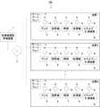
図2は、実施の形態1に係る給湯機運転管理システムの構成例を示すブロック図である。給湯機運転管理システム100は、給湯機運転管理装置1と、ホームゲートウェイ3とを備える。ホームゲートウェイ3は、住居1〜Nを所定地域内の集合体として構成する合計N戸の一戸建て住宅に、それぞれ設置される。なお、本実施の形態では、2以上の住居を想定しているが、N=1であってもよい。給湯機運転管理装置1と各ホームゲートウェイ3とは、有線方式または無線方式、あるいは、これらを組み合わせた方式の通信ネットワーク2を介して接続されている。なお、通信ネットワーク2は、公衆の用に供される共用通信回線や独自の専用通信回線などでもよく、それらを組み合わせたものでもよい。 FIG. 2 is a block diagram illustrating a configuration example of the water heater operation management system according to the first embodiment. The water heater
図1に示す太陽光パネル22、パワーコンディショナ23、電力メータ24、分電盤25は、所定地域内の集合体に接続されて、集合体で共有する構成としてもよいし、各住居(N戸)にそれぞれ1組ずつ接続されていてもよい。また、太陽光発電システムを備える住居と備えない住居が混在する集合体であってもよい。 The
図2の例では、各住居には、所定の機能を居住者に提供する電気機器として、テレビ5、空調機6、照明7および給湯機8が設置され、各電気機器にはそれぞれ通信機器4が接続されている。各通信機器4は、宅内ネットワークを介してホームゲートウェイ3に接続されている。 In the example of FIG. 2, a television 5, an
ホームゲートウェイ3は、同じ住居に設置されたテレビ5、空調機6、照明7および給湯機8の稼働状態を示す稼働データを各電気機器の通信機器4から取得して、各電気機器の稼働状態を監視する。各住居に設置される電気機器は、これに限らず、例えば、換気扇、IHクッキングヒータ、電子レンジ、冷蔵庫、炊飯器、パソコン、ルームエアコン、床暖房、電動窓、電動ブラインドなど、宅内ネットワークを介して監視・制御ができる機器であればよい。 The
エネルギー計測装置9は、宅内ネットワークに接続されており、各住居のブレーカに分岐回路毎に取り付けられたCTセンサなどから、宅内ネットワーク接続された電気機器の消費電力だけでなく、宅内ネットワーク接続されていない電気機器の消費電力を含む、各住居全体の消費電力を示す消費電力データを収集する。また、エネルギー計測装置9は、太陽光発電による発電電力を示す発電電力データも合わせて収集する。 The
ホームゲートウェイ3は、エネルギー計測装置9の通信機器4から消費電力データおよび発電電力データを取得する。ホームゲートウェイ3は、各電気機器の通信機器4から取得した稼働データと、エネルギー計測装置9の通信機器4から取得した消費電力データおよび発電電力データ(以下、稼働データ、消費電力データおよび発電電力データを総称して電気機器動作データという)に収集された日時を示す収集日時を付与して給湯機運転管理装置1に送信する。 The
給湯機運転管理装置1は、各住居に設置される各ホームゲートウェイ3から取得する電気機器動作データと外部から取得する気象情報とに基づいて、各住居に設置された給湯機8の運転スケジュールを決定する。給湯機運転管理装置1は、決定した運転スケジュールを示すスケジュール情報を対応する住居のホームゲートウェイ3に送信する。ホームゲートウェイ3は、給湯機運転管理装置1から受信したスケジュール情報に基づいて、給湯機8の沸き上げ運転を制御する。 The water heater
図3は、実施の形態1に係るホームゲートウェイの機能構成例を示す図である。ホームゲートウェイ3は、電力データ取得部31と、稼働データ取得部32と、ホームゲートウェイ通信部33と、給湯機制御部34とを備える。住居1〜Nの各々に設置されるホームゲートウェイ3は同様の機能構成である。図3では、通信機器4を省略している。 FIG. 3 is a diagram illustrating a functional configuration example of the home gateway according to the first embodiment.
電力データ取得部31は、エネルギー計測装置9から消費電力データおよび発電電力データを取得する。消費電力データは、例えば、宅内ネットワークに接続されているテレビ5、空調機6、照明7、給湯機8の消費電力を示すデータ、宅内ネットワークに接続されていないドライヤーや掃除機などの消費電力を示すデータなどである。 The power
稼働データ取得部32は、テレビ5、空調機6、照明7および給湯機8の各々の稼働状態を示す稼働データを取得する。稼働データは、例えば、テレビ5の電源のオン/オフや音量、空調機6の運転モードや設定温度、電源のオン/オフの予約時刻、給湯機8の貯湯量や設定温度などである。 The operation
電力データ取得部31は、稼働データ取得部32により取得された稼働データに基づいて、あらかじめ記憶する単位時間あたりの消費電力を示す情報を用いて各電気機器の各々の消費電力を算出してもよい。また、電気機器が単独で自らの消費電力データをホームゲートウェイ3に送信できる場合は、エネルギー計測装置9を介する必要はない。 The power
ホームゲートウェイ通信部33は、例えば通信ネットワーク2を介して給湯機運転管理装置1との間で各種データを授受する通信インタフェースであって、ホームゲートウェイ通信部33は、電力データ取得部31および稼働データ取得部32が取得した電気機器動作データを給湯機運転管理装置1に送信する。また、ホームゲートウェイ通信部33は、給湯機運転管理装置1からスケジュール情報を受信する。 The home
給湯機制御部34は、ホームゲートウェイ通信部33が給湯機運転管理装置1から受信したスケジュール情報に基づいて、給湯機8に制御指示を送り、沸き上げ運転を制御する。 The
図4は、実施の形態1に係る給湯機の一例を示す図である。図4の例では、給湯機8は、ヒートポンプ式加熱器801と貯湯タンク802が水流路803によって連通される。ヒートポンプ式加熱器801では、蒸発器814で空気中の熱を媒体が吸収し、圧縮器811で圧縮されてさらに高温になった媒体が放熱器812に送られる。水流路803を通る水は、循環ポンプ804によって放熱器812に導かれ、放熱器812の水冷媒熱交換作用により加熱されて、貯湯タンク802に供給される。ヒートポンプ式加熱器801の膨張弁813は、高圧になった媒体を膨張させて再び液化させる。 FIG. 4 is a diagram illustrating an example of a water heater according to the first embodiment. In the example of FIG. 4, the
貯湯タンク802の貯湯量は、貯湯センサ群821により監視される。貯湯センサ群821は、貯湯タンク802の貯湯量を示す情報をホームゲートウェイ3の稼働データ取得部32に送る。また、ヒートポンプ式加熱器801は、稼働状態を示す稼働データを稼働データ取得部32に送る。ヒートポンプ式加熱器801は、給湯機制御部34から送られる制御指示に従って、稼働する。 The amount of hot water stored in the hot
図5は、実施の形態1に係る給湯機の他の例を示す図である。図5の例では、給湯機8は、図4に示す給湯機8の構成に加えて、ラジエーター805、床暖房機器806、流路調整弁807を備える。図5に示す給湯機8は、ヒートポンプ式加熱器801で加熱された湯を、貯湯タンク802、または、ラジエーター805および床暖房機器806による暖房機器のいずれに循環させるかを流路調整弁807の開閉により操作する。つまり、図5に示す給湯機8は、給湯機能と暖房機能とを兼ね備える。流路調整弁807は、弁の向き、すなわち給湯機8の給湯または暖房のいずれで動作しているかを示す稼働データを稼働データ取得部32に送る。流路調整弁807は、給湯機制御部34から送られる制御指示に従って、開閉する。 FIG. 5 is a diagram illustrating another example of the water heater according to the first embodiment. In the example of FIG. 5, the
なお、図4および図5では、ヒートポンプ式加熱器801で湯を生成する例を示したが、これに限らず、電熱ヒーターなどを用いて湯を生成する給湯機など、電気で湯を生成する電気式給湯機であればよい。 4 and 5 show an example in which hot water is generated by the
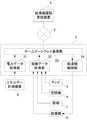
図6は、実施の形態1に係る給湯機運転管理装置の機能構成例を示す図である。給湯機運転管理装置1は、通信部11と、在宅判定部12と、気象情報取得部13と、記憶部14と、在宅予測部15と、余剰電力予測部16と、スケジュール決定部17とを備える。 FIG. 6 is a diagram illustrating a functional configuration example of the water heater operation management device according to the first embodiment. The water heater
通信部11は、例えば通信ネットワーク2を介して各種データを送受信する通信インタフェースである。通信部11は、各ホームゲートウェイ3から受信した電気機器動作データを記憶部14に記憶する。在宅判定部12は、記憶部14に蓄積された電気機器動作データに基づいて、所定の単位時間毎の各住居における居住者の在宅状態を判定し、判定した在宅状態を示す在宅状態データを生成する。 The communication unit 11 is a communication interface that transmits and receives various data via the
例えば、着目する住居において、ある所定の単位時間内に消費電力の変化、各電気機器の稼働状態の変化があった場合、該所定の単位時間内の在宅状態は在宅と判定し、変化がなかった場合は不在と判定する。在宅判定部12は、生成した在宅状態データを記憶部14に記憶する。 For example, if there is a change in power consumption or a change in the operating state of each electrical device within a certain unit time at the residence of interest, the home state within the predetermined unit time is determined to be at home and there is no change. If it is found, it is determined to be absent. The
本実施の形態では、居住者が在宅しているか否かの在宅状態を「1」か「0」の値で示し、居住者が在宅している状態を「0」、居住者が不在の状態を「1」と表し、この値を状態値と呼ぶ。ここで所定の単位時間とは、在宅判定部12が在宅状態を判定する判定周期を示し、通信部11が電気機器動作データを受信する受信周期以上の時間間隔であればよい。例えば、判定周期を60分とし、電気機器動作データの受信周期を1分とする。この場合、在宅判定部12は、60周期分の電気機器動作データの推移に基づいて在宅状態を判定する。 In the present embodiment, the home status indicating whether the resident is at home is indicated by a value of “1” or “0”, the resident status is “0”, and the resident status is absent. Is represented as “1”, and this value is referred to as a state value. Here, the predetermined unit time indicates a determination cycle in which the
本実施の形態では、エネルギー計測装置9は電気機器の消費電力データを収集し、給湯機運転管理装置1は、これを在宅状態の判定に用いる。しかし、これに限らず、エネルギー計測装置9はガスや水道などの使用量データを収集し、給湯機運転管理装置1は、これを在宅状態の判定に用いてもよい。 In this Embodiment, the
気象情報取得部13は、通信部11を介して各住居の所在地を含む地域の過去、現在および将来の気象情報を取得する。気象情報は、例えば、屋外の気温、湿度、天気などである。これらの取得した気象情報は、記憶部14に記憶され、データが蓄積される。 The weather
記憶部14は、ホームゲートウェイ3から受信した電気機器動作データと、在宅判定部12が生成した在宅状態データと、気象情報取得部13が取得した気象情報とを記憶する。さらに、記憶部14は、インターネットや標準電波の送信局などから取得した、年月日時分秒および曜日を含む日時を示す日時データを記憶しており、電気機器動作データの収集日時と対応付けられている。 The
図7は、実施の形態1に係る稼働データの一例を示す図である。稼働データは、収集された日時を示す収集日時と、電気機器の種別を示す機器種別と、該電気機器の稼働状態を示す状態1、状態2および状態3とを含んでいる。例えば、テレビの状態1は電源のオン/オフを示し、状態2は設定された音量を示し、状態3は選択された視聴チャンネルを示す。 FIG. 7 is a diagram illustrating an example of operation data according to the first embodiment. The operation data includes a collection date and time indicating the collected date and time, a device type indicating the type of the electric device, and states 1, 2 and 3 indicating the operation state of the electric device. For example,
在宅判定部12は、所定の単位時間内の稼働データを参照し、少なくともいずれかの電気機器の状態1、状態2および状態3に変化があった場合、該所定の単位時間内の在宅状態は在宅と判定する。なお、稼働データが示す電気機器の稼働状態は3つに限らず1つ以上であればよい。 The
在宅予測部15は、記憶部14の日時データ、気象情報および在宅状態データに基づいて、各住居の将来の在宅状態を予測し、予測した在宅状態を示す予測在宅状態データを生成する。なお、在宅予測部15が在宅状態データのみに基づいて、各住居の将来の在宅状態を予測してもよい。 The
余剰電力予測部16は、記憶部14の日時データおよび気象情報と、電気機器動作データに含まれる消費電力データおよび発電電力データとに基づいて、各住居の将来の余剰電力を予測し、予測した余剰電力(以下、予測余剰電力という)の値を示す予測余剰電力データを生成する。 The surplus
スケジュール決定部17は、在宅予測部15により生成された予測在宅状態データと余剰電力予測部16により生成された予測余剰電力データとに基づいて、各住居に設置された給湯機の沸き上げ運転を行う運転スケジュールを決定し、決定した運転スケジュールを示すスケジュール情報を生成する。 Based on the predicted home state data generated by the
通信部11は、スケジュール決定部17により生成されたスケジュール情報を、対応する住居のホームゲートウェイ3に送信する。このようにして、給湯機運転管理装置1は、各住居の給湯機8が沸き上げ運転を行う時間帯を管理する。 The communication unit 11 transmits the schedule information generated by the
次に、本実施の形態に係る給湯機運転管理システム100が実行する各処理について説明する。各処理は、予め定められた周期で実行される。ホームゲートウェイ3は、「電気機器動作データ収集処理」を実行する。 Next, each process performed by the water heater
(電気機器動作データ収集処理)
図8は、実施の形態1に係る電気機器動作データ収集処理の動作の一例を示すフローチャートである。ホームゲートウェイ3の稼働データ取得部32は、テレビ5、空調機6、照明7、給湯機8のそれぞれから、稼働データを取得する(ステップS11)。電力データ取得部31は、エネルギー計測装置9から、消費電力データおよび発電電力データを取得する(ステップS12)。(Electrical equipment operation data collection processing)
FIG. 8 is a flowchart showing an example of the operation of the electrical equipment operation data collection process according to the first embodiment. The operation
ホームゲートウェイ通信部33は、稼働データ取得部32および電力データ取得部31が取得した稼働データ、消費電力データおよび発電電力データを電気機器動作データとして、通信ネットワーク2を介して給湯機運転管理装置1に送信し(ステップS13)、処理を終了する。 The home
ホームゲートウェイ3が電気機器動作データ収集処理を実行するタイミングは、例えば前述のように1分周期とする。しかし、これに限らず、判定周期より短い周期であればよい。また、電気機器動作データは、ステップS13で逐次送信されることに代えて、例えば、ホームゲートウェイ3に記憶部を設け、1日などの一定期間分の電気機器動作データを記憶してもよい。この場合、ホームゲートウェイ通信部33が一定期間分の電気機器動作データを一単位としてまとめて給湯機運転管理装置1に送信する。また、必要に応じて一定期間内の値を平均化する処理、積算する処理などを行ってもよい。 The timing at which the
給湯機運転管理装置1は、「在宅状態判定処理」、「在宅状態予測処理」、「気象情報取得処理」、「余剰電力予測処理」および「運転スケジュール決定処理」を実行する。 The water heater
(在宅状態判定処理)
図9は、実施の形態1に係る在宅状態判定処理の動作の一例を示すフローチャートである。給湯機運転管理装置1の在宅判定部12は、直前の1判定周期分の電気機器動作データを記憶部14から読み出す(ステップS21)。在宅判定部12では、直前の1判定周期分の電気機器動作データを参照し、テレビ5の稼働状態に変化があったか否かを判定する(ステップS22)。(Home status determination process)
FIG. 9 is a flowchart illustrating an example of the operation of the home state determination process according to the first embodiment. The at-
テレビ5の稼働状態に変化があった場合(ステップS22;Yes)、在宅判定部12は、居住者が在宅していると判定し、在宅状態データの該時間帯の状態値を「0」に設定し(ステップS27)、処理を終了する。テレビ5の稼働状態に変化がない場合(ステップS22;No)、在宅判定部12は、直前の1判定周期分の電気機器動作データを参照し、空調機6の稼働状態に変化があったか否かを判定する(ステップS23)。 When there is a change in the operating state of the television 5 (step S22; Yes), the
空調機6の稼働状態に変化があった場合(ステップS23;Yes)、在宅判定部12は、居住者が在宅していると判定し、在宅状態データの該時間帯の状態値を「0」に設定し(ステップS27)、処理を終了する。空調機6の稼働状態に変化がない場合(ステップS23;No)、在宅判定部12は、直前の1判定周期分の電気機器動作データを参照し、照明7の稼働状態に変化があったか否かを判定する(ステップS24)。 When there is a change in the operating state of the air conditioner 6 (step S23; Yes), the
照明7の稼働状態に変化があった場合(ステップS24;Yes)、在宅判定部12は、居住者が在宅していると判定し、在宅状態データの該時間帯の状態値を「0」に設定し(ステップS27)、処理を終了する。照明7の稼働状態に変化がない場合(ステップS24;No)、在宅判定部12は、直前の1判定周期分の電気機器動作データを参照し、給湯機8の稼働状態に変化があったか否かを判定する(ステップS25)。 When there is a change in the operating state of the lighting 7 (step S24; Yes), the
給湯機8の稼働状態に変化があった場合(ステップS25;Yes)、在宅判定部12は、居住者が在宅していると判定し、在宅状態データの該時間帯の状態値を「0」に設定し(ステップS27)、処理を終了する。給湯機8の稼働状態に変化がない場合(ステップS25;No)、つまり、宅内ネットワークに接続されているすべての電気機器の稼働状態に変化がない場合、在宅判定部12は、直前の1判定周期分の電気機器動作データを参照し、住居全体の消費電力量もしくは分岐回路毎の消費電力量に変化があったか否かを判定する(ステップS26)。これにより、宅内ネットワークに接続されておらず、ホームゲートウェイ3で稼働データを収集できない電気機器の稼働状態の変化を検出することができる。 When there is a change in the operating state of the water heater 8 (step S25; Yes), the
住居全体の消費電力量もしくは分岐回路毎の消費電力量に変化があった場合(ステップS26;Yes)、在宅判定部12は、居住者が在宅していると判定し、在宅状態データの該時間帯の状態値を「0」に設定し(ステップS27)、処理を終了する。住居全体の消費電力量もしくは分岐回路毎の消費電力量に変化がなかった場合(ステップS26;No)、在宅判定部12は、居住者が不在であると判定し、在宅状態データの該時間帯の状態値を「1」に設定し(ステップS28)、処理を終了する。 When there is a change in the power consumption of the entire residence or the power consumption of each branch circuit (step S26; Yes), the
給湯機運転管理装置1が在宅状態判定処理を実行するタイミングは、例えば前述のように60分周期とする。しかし、これに限らず、電気機器動作データの受信周期より長い周期であればよい。 The timing at which the hot water heater
なお、ステップS22〜S25で在宅状態を判定する材料となる対象の電気機器は、随時変更することが可能である。例えば、帰宅した際に室内が適度な温度になるよう在宅前から空調機6の運転が開始するよう予約時刻が設定されている場合などに、あらかじめ、在宅状態を判定する材料となる対象の電気機器から空調機6を外すことで、不在中に動作される電気機器の稼働状態の変化によって、誤った在宅状態が判定されることを防止することができる。 In addition, the electric equipment of the object used as the material which determines a home state in step S22-S25 can be changed at any time. For example, when the reservation time is set so that the operation of the
また、ステップS26で判定される消費電力量についても同様に、対象の分岐回路を随時変更することが可能である。これにより、不在中に動作される電気機器の稼働状態の変化によって、誤った在宅状態が判定されることを防止することができる。 Similarly, for the power consumption determined in step S26, the target branch circuit can be changed at any time. Accordingly, it is possible to prevent an erroneous home state from being determined due to a change in the operating state of an electrical device that is operated during the absence.
(在宅状態予測処理)
図10は、実施の形態1に係る在宅状態予測処理の動作の一例を示すフローチャートである。給湯機運転管理装置1の記憶部14は、24時間分の在宅状態データをまとめて、日別在宅状態データとして記憶する。在宅予測部15は、記憶部14から、直近の所定の日数分の日別在宅状態データのうち、運転スケジュールを設定する日と同一の日時や、曜日、気象など所定の条件に当てはまる日別在宅状態データを読み出す(ステップS31)。(Home status prediction process)
FIG. 10 is a flowchart illustrating an example of the home state prediction process according to the first embodiment. The
図11は、実施の形態1に係る日別在宅状態データの一例を示す図である。日別在宅状態データは、判定日と1時間ごとの判定時刻と判定時刻ごとの状態値が含まれる。図11の例では、9時から22時まで不在である。 FIG. 11 is a diagram illustrating an example of daily home status data according to the first embodiment. The daily home status data includes a determination date, a determination time for each hour, and a state value for each determination time. In the example of FIG. 11, it is absent from 9:00 to 22:00.
在宅予測部15は、読み出した日別在宅状態データの状態値の平均(平均状態値)を、判定時刻ごとに算出する(ステップS32)。在宅予測部15は、平均状態値と、あらかじめ設定された閾値とを比較する(ステップS33)。 The
平均状態値が閾値よりも大きい場合(ステップS33;Yes)、在宅予測部15は、予測在宅状態データの該時刻の状態値を「1」に設定し(ステップS34)、処理を終了する。平均状態値が閾値よりも小さい場合(ステップS33;No)、予在宅予測部15は、測在宅状態データの該時刻の状態値を「0」に設定し(ステップS35)、処理を終了する。 When the average state value is larger than the threshold (step S33; Yes), the
給湯機運転管理装置1は、この処理(ステップS31〜ステップS35)を、すべての住居の日別在宅状態データについて実行する。 The water heater
具体的には、例えば、住居1の第四水曜日の朝7時〜7時半の予測在宅状態データを同じ月の同じ曜日の在宅状態データに基づいて算出する場合、在宅予測部15は、直近21日(3週間)分の住居1の日別在宅状態データのうち、第一、第二、第三水曜日の朝7時〜7時半の在宅状態データ3個を読み出す。第一水曜日の在宅状態データが状態値「1(不在)」、第二水曜日の在宅状態データが状態値「0(在宅)」、第三水曜日の在宅状態データが状態値「1(不在)」であった場合、平均状態値は「0.66…」となる。 Specifically, for example, when calculating the predicted home state data from 7 am to 7:30 in the morning of the fourth Wednesday of the
ここで、閾値が「0.5」に設定されていた場合、在宅予測部15は、平均状態値が閾値より大きいので在宅状態を「不在」と予測し、予測在宅状態データの第四水曜日の朝7時〜7時半の状態値を「1」に設定する。 Here, when the threshold is set to “0.5”, the
以上のように、運転スケジュールを設定する日と同条件の日時データを用いて予測在宅状態を予測することで、居住者の生活スケジュールを高精度に予測することができる。また、気象情報を用いて在宅状態を予測することで、予測精度をさらに高くすることができる。 As described above, it is possible to predict the resident's life schedule with high accuracy by predicting the predicted home state using the date and time data having the same conditions as the day for setting the driving schedule. Moreover, prediction accuracy can be further increased by predicting the home state using weather information.
例えば、雨の予報が出されている6月6日の18時〜18時半の予測在宅状態データを、雨が降った過去5日分の在宅状態データに基づいて算出する場合、在宅予測部15は、直近56日(8週間)分の住居Aの日別在宅状態データのうち、直近5日分の雨が降った6月5日、5月22日、5月21日、5月5日、4月30日の18時〜18時半の在宅状態データ5個を読み出す。これらの在宅状態データがそれぞれ状態値「0」、状態値「0」、状態値「0」、状態値「1」、状態値「0」であった場合、平均状態値は「0.2」となる。 For example, when calculating the predicted home state data from 18:00 to 18:30 on June 6 for which a rain forecast has been issued based on the home state data for the past five days when it rained, the
ここで、閾値が「0.5」に設定されていた場合、在宅予測部15は、平均状態値が閾値より小さいので在宅状態を「在宅」と予測し、予測在宅状態データの6月6日の18時〜18時半の状態値を「0」に設定する。 Here, when the threshold is set to “0.5”, the
在宅状態を予測するための閾値は、随時変更させることが可能であり、閾値を0.5よりも大きな値(例えば0.7)に設定して不在判定を厳しくしてもよいし、逆に閾値を0.5よりも小さな値(例えば0.3)に設定して不在と判定され易くしてもよい。例えば、判定対象のすべての時間帯で不在である場合にのみ予測在宅状態を不在判定としたいのであれば、閾値を1に設定すればよい。 The threshold for predicting the home status can be changed at any time, and the threshold may be set to a value larger than 0.5 (for example, 0.7) to make the absence determination stricter. The threshold value may be set to a value smaller than 0.5 (for example, 0.3) to make it easier to determine absence. For example, the threshold may be set to 1 if it is desired that the predicted home state is determined to be absent only when it is absent in all time zones to be determined.
給湯機運転管理装置1の在宅予測部15は、例えば、運転スケジュールを設定する日の直前(例えば前日の23時)のタイミングで、各住居の翌日の在宅状態を予測する在宅状態予測処理を実行する。在宅予測部15が在宅状態予測処理を実行するタイミングは、記憶部14に必要なデータが揃ったタイミングでもよい。しかし、直前に在宅状態予測処理を実行した方が、予測在宅状態データをいったん記憶部14に保存する必要がなく、記憶部14のメモリ容量を減らすことができるといった利点がある。 The
なお、本実施の形態では平均状態値を閾値と比較することで予測在宅状態を判別したが、平均を用いず、複数の状態値から「0」「1」の個数の多さ(多数決)により在宅状態を予測してもよい。 In the present embodiment, the predicted home state is determined by comparing the average state value with the threshold value, but the average is not used, and the number of “0” and “1” is determined from a plurality of state values (majority decision). You may predict a home state.
(余剰電力予測処理)
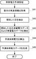
図12は、実施の形態1に係る余剰電力予測処理の動作の一例を示すフローチャートである。給湯機運転管理装置1の余剰電力予測部16は、記憶部14から翌日の気象情報を読み出す(ステップS41)。(Surplus power prediction process)
FIG. 12 is a flowchart illustrating an example of operation of surplus power prediction processing according to the first embodiment. The surplus
次に、余剰電力予測部16は、記憶部14が記憶する過去の気象情報から翌日の気象情報に類似する日を抽出する(ステップS42)。翌日の気象情報に類似する日とは、例えば、翌日の日照予測時間帯と過去の日照時間帯とが最も近い日である。 Next, the surplus
余剰電力予測部16は、記憶部14から類似する日の各時間帯の消費電力データと発電電力データを読み出し(ステップS43)、読み出した消費電力データと発電電力データに基づいて、各時間帯の余剰電力を予測する(ステップS44)。余剰電力予測部16は、予測余剰電力の値を示す予測余剰電力データを生成し(ステップS45)、処理を終了する。 The surplus
給湯機運転管理装置1の余剰電力予測部16は、例えば、運転スケジュールを設定する直前(例えば前日の23時)のタイミングで、各住居の翌日の余剰電力を予測する余剰電力予測処理を実行する。各住居の時間帯毎の予測余剰電力の値は例えば、数1の計算式で算出される。 The surplus

ここで、Psiはある時間帯における住居i(iは1〜Nのいずれか)の予測余剰電力、Pgiは同一時間帯における住居iの発電電力、Pciは同一時間帯における住居iの消費電力、Pbiは同一時間帯が沸き上げ運転予約時間に含まれる場合のこの時間帯における給湯機8の消費電力を示し、いずれもステップS43において、記憶部14から読み出される。住居iが太陽光発電システムを備えていない場合、Pgiは常に0であり、時間帯によらずPsi=0となる。 Here, Psi is the predicted surplus power of residence i (i is any one of 1 to N) in a certain time zone, Pgi is the generated power of residence i in the same time zone, Pci is the power consumption of residence i in the same time zone, Pbi indicates the power consumption of the
なお、過去の気象情報から翌日の気象情報に類似する日を抽出する方法は、所定の気象条件の最も近い日を選択する場合だけでなく、所定の気象条件の値が近い順に複数日(5日分など)を抽出してもよい。この場合、類似する複数日の平均値を取って予測余剰電力を算出するとよい。また、発電電力データは気象情報が類似する複数日の平均値を取り、消費電力データは曜日が一致した日の平均値を取る、といったように、予測余剰電力の算出方法は用途に合わせて異なってもよい。 In addition, the method of extracting the day similar to the weather information of the next day from the past weather information is not only for selecting the day closest to the predetermined weather condition, but also for multiple days (5 Day)) may be extracted. In this case, the predicted surplus power may be calculated by taking an average value of a plurality of similar days. In addition, the calculation method of predicted surplus power differs depending on the application, such as the average value for multiple days with similar weather information and the average value for the day with the same day of the week. May be.
(運転スケジュール決定処理1)
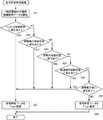
図13は、実施の形態1に係る運転スケジュール決定処理の動作の一例を示すフローチャートである。給湯機運転管理装置1のスケジュール決定部17は、余剰電力予測処理で生成された予測余剰電力データに基づいて、時間帯毎に各住居の予測余剰電力Psiを加算し、集合体の予測余剰電力を算出する(ステップS51)。ただし、太陽光発電システムを集合体で共有する場合、集合体の予測余剰電力は、全住居のPsi総和ではなく、数2の計算式で算出される。(Driving schedule determination process 1)
FIG. 13 is a flowchart illustrating an example of the operation of the operation schedule determination process according to the first embodiment. The
Pgは集合体で共有される太陽光発電システムの発電電力を示す。スケジュール決定部17は、集合体の予測余剰電力が給湯機8の沸き上げ運転による消費電力以上となる時間帯(以下、余剰電力発生時間帯という)があるか否かを判定する(ステップS52)。余剰電力発生時間帯がない場合(ステップS52;No)、スケジュール決定部17は、沸き上げ運転を割り当てられていない未設定の住居(全住居)の給湯機8の沸き上げ運転を通常の時間帯(夜間)に設定する(ステップS58)。 Pg indicates the generated power of the solar power generation system shared by the aggregate. The
余剰電力発生時間帯がある場合(ステップS52;Yes)、スケジュール決定部17は、在宅状態予測処理で生成された予測在宅状態データに基づいて、余剰電力発生時間帯に不在となる住居があるか否かを判定する(ステップS53)。 If there is a surplus power generation time zone (step S52; Yes), the
余剰電力発生時間帯に不在宅となる住居がある場合(ステップS53;Yes)、スケジュール決定部17は、該当する住居のうち、残湯量の多い順(沸き上げ湯量の少ない順)に優先順位を決定する(ステップS54)。スケジュール決定部17は、優先順位が最上位の住居の給湯機8の沸き上げ運転を余剰電力発生時間帯に設定する(ステップS55)。 When there is a residence that is not in the surplus power generation time zone (step S53; Yes), the
続いて、スケジュール決定部17は、給湯機8の沸き上げ運転を余剰電力発生時間帯に設定した住居を除外し(ステップS56)、余剰電力発生時間帯の予測余剰電力から給湯機8の沸き上げ運転に必要な消費電力を減算する(ステップS57)。処理はステップS52に戻り、余剰電力発生時間帯がなくなるか、余剰電力発生時間帯に不在宅となるすべての住居の給湯機8の沸き上げ運転が割り当てられ、余剰電力発生時間帯に不在となる住居がなくなるまで、ステップ52〜ステップ57を繰り返す。 Then, the
余剰電力発生時間帯がなくなるか(ステップS52;No)、余剰電力発生時間帯に不在となる住居がなくなると(ステップS53;No)、スケジュール決定部17は、沸き上げ運転を割り当てられていない残りの未設定の住居の給湯機8の沸き上げ運転を通常の時間帯(夜間)に設定する(ステップS58)。 When there is no surplus power generation time zone (step S52; No), or when there are no residences that are absent in the surplus power generation time zone (step S53; No), the
一方、余剰電力発生時間帯に不在宅となる住居がない場合(ステップS53;No)、スケジュール決定部17は、沸き上げ運転を割り当てられていない未設定の住居(全住居)の給湯機8の沸き上げ運転を通常の時間帯(夜間)に設定する(ステップS58)。このとき、余剰電力発生時間帯の予測余剰電力を例えば便宜的に0(ゼロ)に更新してもよい。 On the other hand, when there is no residence that is not at home in the surplus power generation time zone (step S53; No), the
スケジュール決定部17は、全住居の沸き上げ運転スケジュールを示すスケジュール情報を生成し(ステップS59)、通信部11は通信ネットワーク2を介してスケジュール情報を対応する住居のホームゲートウェイ3に送信し(ステップS60)、処理を終了する。 The
各住居に設置されているホームゲートウェイ3のホームゲートウェイ通信部33は、通信ネットワーク2を介して、給湯機運転管理装置1から運転スケジュールを受信すると、給湯機制御部34に送信し、給湯機制御部34は、運転スケジュールに基づいて給湯機8の沸き上げ運転の開始時間および停止時間を制御する。 When the home
なお、ステップS54では残湯量の多い順(沸き上げ湯量の少ない順)に優先順位を決定しているが、これは湯切れの発生する確率が低い順に優先度を付けて、居住者の快適性を損なわないためである。優先順位を決定する方法は、例えば、各住居の消費電力量の少ない順など用途に合わせて変更してもよい。また、住居が1つの場合は、自動的にその住居が優先順位1位になる。 In step S54, priority is determined in descending order of the amount of remaining hot water (in order of increasing amount of boiling hot water). It is because it does not impair. The method for determining the priority order may be changed in accordance with the application, for example, in order of decreasing power consumption of each residence. Moreover, when there is one residence, the residence automatically becomes the first priority.
給湯機運転管理装置1のスケジュール決定部17は、あらかじめ設定されたタイミングで、運転スケジュール決定処理を実行する。 The
本実施の形態では、在宅状態予測処理で生成された予測在宅状態データに基づいて、余剰電力発生時間帯に不在となる住居があるか否かを判定しているが、これに限らない。例えば、運転スケジュールを設定する直前のタイミングで、各住居の翌日の余剰電力を予測する余剰電力予測処理を実行する場合には、在宅判定部12が生成したリアルタイムの在宅状態データに基づいて、不在となっている住居があるか否かを判定してもよい。この場合、給湯機運転管理装置1は、在宅予測部15を備えなくてもよい。 In the present embodiment, based on the predicted home state data generated in the home state prediction process, it is determined whether there is a residence that is absent in the surplus power generation time period, but is not limited thereto. For example, when executing surplus power prediction processing for predicting surplus power on the next day of each residence at the timing immediately before setting the operation schedule, the absence based on the real-time home status data generated by the
以上説明したように、本実施の形態1の給湯機運転管理システム100によれば、気象条件に応じて発電量が変化する発電システムが電源系統につながっている場合において、1または2以上の住居の電気式の給湯機の沸き上げ運転を最適なタイミングで行うことができ、蓄電池を用いる場合よりも低コストで余剰電力を有効活用し、電力の平準化を実現することができる。さらに、居住者の生活スケジュールを考慮し、給湯機で沸き上げたお湯の使用を必要としない時間帯を中心に給湯機の沸き上げ運転時間帯を設定することで、居住者の快適性を保ちつつ、効率的に太陽光発電による余剰電力の活用を図ることができる。 As described above, according to the hot water heater
実施の形態2.
双方向情報通信機能を備えた電力計であるスマートメーターを介して、電力会社(供給側)と住宅などの需要家(需要側)の双方向通信による情報伝達を実現させ、電力の価格情報が電力会社から需要家に送られ、需要家内のHEMS(Home Energy Management System)は、その価格情報に基づいて家電機器を最適に制御する、といったデマンドレスポンス技術がある。
Through the smart meter, which is a wattmeter equipped with a two-way information communication function, information transmission through the two-way communication between the power company (supply side) and the consumer (demand side) such as a house is realized. There is a demand response technology in which a home energy management system (HEMS) sent from an electric power company to a consumer optimally controls home appliances based on the price information.
一般的にデマンドレスポンスは電力使用のピーク時間の電気代を高くすることでピーク時間の電気使用量を抑制し、平準化する技術であるが、ここでは、余剰電力が発生する時間帯の電気使用量を増やすことで、余剰電力を活用することに用いる。実施の形態2では、実施の形態1の電力メータ24にスマートメーターを採用することで、よりリアルタイム性を持たせて太陽光発電による余剰電力の活用を図る。 In general, demand response is a technology that suppresses the level of electricity usage during peak hours by increasing the electricity bill during peak hours of electricity use, and here, it uses electricity during times when surplus power is generated. It is used to utilize surplus power by increasing the amount. In the second embodiment, a smart meter is employed as the
実施の形態2に係る給湯機運転管理システムの基本構成は、実施の形態1に係る給湯機運転管理システム100と同様である。実施の形態1と同一又は同等な構成部分については同一符号を付し、その説明を省略する。 The basic configuration of the water heater operation management system according to
実施の形態2に係る給湯機運転管理装置1は、少なくとも通信部11、記憶部14およびスケジュール決定部17を備える。実施の形態2に係る運転スケジュール決定処理は、電力会社が太陽光発電による余剰電力が発生すると判定した時間帯に給湯機8などの家電機器を電力会社が自動で制御することを許可する契約をした契約住居を対象とする。例えば、契約の内容として、余剰電力を活用して電源系統の安定化に協力してもらうため、その時間帯の電気代を減額するなど、需要家にとってもメリットを享受できるようにすることが考えられる。本実施の形態では、住居1〜Nに1以上の契約住居が含まれる。 The water heater
(運転スケジュール決定処理2)
図14は、実施の形態2に係る運転スケジュール決定処理の動作の一例を示すフローチャートである。電力会社は太陽光発電による電力供給量が増大して集合体の余剰電力が発生すると判定すると、該集合体の余剰電力が発生すると判定した時間帯と算出した余剰電力の値とを示す余剰電力情報をスマートメーターに送信する。スマートメーターは、受信した余剰電力情報を給湯機運転管理装置1の通信部11に送信する。(Driving schedule determination process 2)
FIG. 14 is a flowchart illustrating an example of the operation of the operation schedule determination process according to the second embodiment. When the electric power company determines that the power supply amount by solar power generation increases and surplus power of the aggregate is generated, surplus power indicating the time zone determined that surplus power of the aggregate is generated and the calculated surplus power value Send information to the smart meter. The smart meter transmits the received surplus power information to the communication unit 11 of the water heater
給湯機運転管理装置1の通信部11は、余剰電力情報を受信しない場合(ステップS61;No)、ステップS61を繰り返し、余剰電力情報の受信を待機する。通信部11が余剰電力情報を受信した場合(ステップS61;Yes)、スケジュール決定部17は、余剰電力情報が示す時間帯の集合体の余剰電力が給湯機8の沸き上げ運転による消費電力以上となるか否かを判定する(ステップS62)。集合体の余剰電力が給湯機8の沸き上げ運転による消費電力以上とならない場合(ステップS62;No)、スケジュール決定部17は、沸き上げ運転を割り当てられていない未設定の住居(全住居)の給湯機8の沸き上げ運転を通常の時間帯(夜間)に設定する(ステップS68)。 When the surplus power information is not received (step S61; No), the communication unit 11 of the water heater
集合体の余剰電力が給湯機8の沸き上げ運転による消費電力以上となる場合(ステップS62;Yes)、スケジュール決定部17は、あらかじめ記憶部14に記憶しておいた契約住居を示す契約住居情報を参照し、給湯機8の沸き上げ運転時間が割り当てられていない未設定の契約住居があるか否かを判定する(ステップS63)。 When the surplus power of the aggregate is greater than or equal to the power consumed by the heating operation of the water heater 8 (step S62; Yes), the
契約住居がある場合(ステップS63;Yes)、スケジュール決定部17は、契約住居のうち、該時間帯の消費電力が多い順に優先順位を決定する(ステップS64)。スケジュール決定部17は、優先順位が最上位の住居の給湯機8の沸き上げ運転を余剰電力情報が示す時間帯に設定する(ステップS65)。 When there is a contracted residence (step S63; Yes), the
続いて、スケジュール決定部17は、給湯機8の沸き上げ運転を余剰電力情報が示す時間帯に設定した住居を除外し(ステップS66)、余剰電力情報が示す時間帯の余剰電力から給湯機8の沸き上げ運転に必要な消費電力を減算する(ステップS67)。処理はステップS62に戻り、集合体の余剰電力が給湯機8の沸き上げ運転による消費電力より小さくなるか、未設定の契約住居がなくなるまでステップ62〜ステップ67を繰り返す。 Then, the
集合体の余剰電力が給湯機8の沸き上げ運転による消費電力より小さくなるか(ステップS62;No)、未設定の契約住居がなくなると(ステップS63;No)、スケジュール決定部17は、沸き上げ運転を割り当てられていない残りの未設定の住居の給湯機8の沸き上げ運転を通常の時間帯(夜間)に設定する(ステップS68)。このとき、余剰電力情報が示す時間帯の余剰電力を例えば便宜的に0(ゼロ)に更新してもよい。 When the surplus power of the aggregate is smaller than the power consumption by the heating operation of the water heater 8 (step S62; No), or when there is no unset contracted residence (step S63; No), the
スケジュール決定部17は、全住居の沸き上げ運転スケジュールを示すスケジュール情報を生成し(ステップS69)、通信部11は通信ネットワーク2を介してスケジュール情報を電力会社に送信し(ステップS70)、処理を終了する。 The
電力会社は、給湯機運転管理装置1から運転スケジュールを受信すると、運転スケジュールに基づいて契約住居の給湯機8の沸き上げ運転の開始時間および停止時間を制御する。 When the electric power company receives the operation schedule from the hot water heater
なお、ステップS64では余剰電力情報が示す時間帯の消費電力が多い順に優先に優先順位を決定しているが、この時の消費電力は、ホームゲートウェイ3の電力データ取得部31が収集した該当時間におけるリアルタイムでの消費電力でもよいし、過去の消費電力データから予測した消費電力でも構わない。また、契約住居での該時間帯の電気代が減額となるメリットを享受しやすいように、例えば、給湯機運転管理装置1が在宅予測部15を備え、予測在宅状態データが「在宅」となっている契約住居を優先するといったように、用途に合わせて変更しても構わない。 In step S64, the priority order is determined with priority in descending order of power consumption in the time zone indicated by the surplus power information. The power consumption at this time corresponds to the corresponding time collected by the power
以上説明したように、本実施の形態2の給湯機運転管理システムによると、スマートメーターによる電力会社と住宅との双方向通信機能を用いることで、よりリアルタイムに太陽光発電による余剰電力を活用することができる。これにより、電力会社の電源系統の安定化に寄与することができる。 As described above, according to the hot water heater operation management system of the second embodiment, the surplus power generated by photovoltaic power generation is utilized in real time by using the bidirectional communication function between the power company and the house using the smart meter. be able to. Thereby, it can contribute to stabilization of the power supply system of an electric power company.
本実施の形態1および2について別々に説明したが、これらの組み合わせてもよい。また、本実施の形態1および2に係る再生可能エネルギーは、太陽光発電システム以外に風力発電、地熱発電などの手段を採用してもよい。 Although
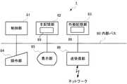
図15は、本発明の実施の形態に係る給湯機運転管理装置のハードウェア構成の一例を示すブロック図である。給湯機運転管理装置1は、図15に示すように、制御部81、主記憶部82、外部記憶部83、操作部84、表示部85および送受信部86を備える。主記憶部82、外部記憶部83、操作部84、表示部85および送受信部86はいずれも内部バス80を介して制御部81に接続されている。 FIG. 15 is a block diagram illustrating an example of a hardware configuration of the water heater operation management device according to the embodiment of the present invention. As shown in FIG. 15, the water heater
制御部81はCPU(Central Processing Unit)などから構成され、外部記憶部83に記憶されている制御プログラム89に従って、給湯機運転管理装置1の在宅判定部12、気象情報取得部13、余剰電力予測部16、在宅予測部15およびスケジュール決定部17の各処理を実行する。 The
主記憶部82はRAM(Random-Access Memory)などから構成され、外部記憶部83に記憶されている制御プログラム89をロードし、制御部81の作業領域として用いられる。 The
外部記憶部83は、フラッシュメモリ、ハードディスク、DVD−RAM、DVD−RWなどの不揮発性メモリから構成され、給湯機運転管理装置1の処理を制御部81に行わせるためのプログラムをあらかじめ記憶し、また、制御部81の指示に従って、このプログラムが記憶するデータを制御部81に供給し、制御部81から供給されたデータを記憶する。記憶部14は外部記憶部83に構成される。 The
操作部84は、キーボードおよびマウスなどのポインティングデバイスなどと、キーボードおよびポインティングデバイスなどを内部バス80に接続するインタフェース装置から構成されている。ユーザが給湯機運転管理装置1に直接情報を入力する場合は、操作部84を介して、入力された情報が制御部81に供給される。 The
表示部85は、CRT(Cathode Ray Tube)またはLCD(Liquid Crystal Display)などから構成されている。表示部85は、ユーザが給湯機運転管理装置1に直接情報を入力する場合は、操作画面を表示する。 The
送受信部86は、ネットワークに接続する網終端装置または無線通信装置、およびそれらと接続するシリアルインタフェースまたはLAN(Local Area Network)インタフェースから構成されている。送受信部86は、通信部11として機能する。 The transmission /
図6に示す給湯機運転管理装置1の通信部11、在宅判定部12、気象情報取得部13、記憶部14、在宅予測部15、余剰電力予測部16およびスケジュール決定部17の処理は、制御プログラム89が、制御部81、主記憶部82、外部記憶部83、操作部84、表示部85および送受信部86などを資源として用いて処理することによって実行する。 The processing of the communication unit 11, the
その他、前記のハードウェア構成やフローチャートは一例であり、任意に変更および修正が可能である。 In addition, the hardware configuration and the flowchart described above are merely examples, and can be arbitrarily changed and modified.
制御部81、主記憶部82、外部記憶部83、操作部84、表示部85、送受信部86、内部バス80などから構成される給湯機運転管理装置1の処理を行う中心となる部分は、専用のシステムによらず、通常のコンピュータシステムを用いて実現可能である。例えば、前記の動作を実行するためのコンピュータプログラムを、コンピュータが読み取り可能な記録媒体(フレキシブルディスク、CD−ROM、DVD−ROMなど)に格納して配布し、当該コンピュータプログラムをコンピュータにインストールすることにより、前記の処理を実行する給湯機運転管理装置1を構成してもよい。また、インターネットなどの通信ネットワーク上のサーバ装置が有する記憶装置に当該コンピュータプログラムを格納しておき、通常のコンピュータシステムがダウンロードなどすることで給湯機運転管理装置1を構成してもよい。 The central part that performs the processing of the water heater
また、給湯機運転管理装置1の機能を、OS(オペレーティングシステム)とアプリケーションプログラムの分担、またはOSとアプリケーションプログラムとの協働により実現する場合などには、アプリケーションプログラム部分のみを記録媒体や記憶装置に格納してもよい。 Further, when the functions of the water heater
また、搬送波にコンピュータプログラムを重畳し、通信ネットワークを介して提供することも可能である。例えば、通信ネットワーク上の掲示板(BBS, Bulletin Board System)に前記コンピュータプログラムを掲示し、ネットワークを介して前記コンピュータプログラムを提供してもよい。そして、このコンピュータプログラムを起動し、OSの制御下で、他のアプリケーションプログラムと同様に実行することにより、前記の処理を実行できるように構成してもよい。 It is also possible to superimpose a computer program on a carrier wave and provide it via a communication network. For example, the computer program may be posted on a bulletin board (BBS, Bulletin Board System) on a communication network, and the computer program may be provided via the network. The computer program may be started and executed in the same manner as other application programs under the control of the OS, so that the above-described processing may be executed.
本発明は、本発明の広義の精神と範囲を逸脱することなく、様々な実施の形態および変形が可能とされるものである。また、上述した実施の形態は、本発明を説明するためのものであり、本発明の範囲を限定するものではない。本発明の範囲は、実施の形態ではなく、特許請求の範囲によって示される。そして、特許請求の範囲内およびそれと同等の発明の意義の範囲内で施される様々な変形が、本発明の範囲内とみなされる。 Various embodiments and modifications can be made to the present invention without departing from the broad spirit and scope of the present invention. The above-described embodiments are for explaining the present invention and do not limit the scope of the present invention. The scope of the present invention is shown not by the embodiments but by the claims. Various modifications within the scope of the claims and within the scope of the equivalent invention are considered to be within the scope of the present invention.
1 給湯機運転管理装置、2 通信ネットワーク、3 ホームゲートウェイ、4 通信機器、5 テレビ、6 空調機、7 照明、8 給湯機、9 エネルギー計測装置、11 通信部、12 在宅判定部、13 気象情報取得部、14 記憶部、15 在宅予測部、16 余剰電力予測部、17 スケジュール決定部、21 電源系統、22 太陽光パネル、23 パワーコンディショナ、24 電力メータ、25 分電盤、31 電力データ取得部、32 稼働データ取得部、33 ホームゲートウェイ通信部、34 給湯機制御部、80 内部バス、81 制御部、82 主記憶部、83 外部記憶部、84 操作部、85 表示部、86 送受信部、89 制御プログラム、100 給湯機運転管理システム、801 ヒートポンプ式加熱器、802 貯湯タンク、803 水流路、804 循環ポンプ、805 ラジエーター、806 床暖房機器、807 流路調整弁、811 圧縮器、812 放熱器、813 膨張弁、814 蒸発器、821 貯湯センサ群。 DESCRIPTION OF
Claims (8)
Translated fromJapanese前記住居に設置された電気機器の稼働状態を示す稼働データを取得する稼働データ取得部と、
前記住居の所在地を含む地域の気象情報を取得する気象情報取得部と、
前記稼働データに基づいて前記住居の居住者が在宅であるか否かを判定し、判定した在宅状態を示す在宅状態データを生成する在宅判定部と、
前記気象情報に基づいて前記発電システムの余剰電力を予測し、予測した余剰電力の発生する時間帯と余剰電力の値とを示す予測余剰電力データを生成する余剰電力予測部と、
前記在宅状態データおよび前記予測余剰電力データに基づいて、前記住居の給湯機を運転させる運転スケジュールを決定し、決定した運転スケジュールを示す運転スケジュール情報を生成する運転スケジュール決定部と、
を備える給湯機運転管理装置。A water heater operation management device that controls the operation of electric water heaters installed in one or two or more houses, each of which has a power generation system whose power generation amount changes according to weather conditions, connected to the power system.
An operation data acquisition unit that acquires operation data indicating an operation state of the electrical equipment installed in the residence;
A weather information acquisition unit for acquiring weather information of a region including the location of the residence;
It is determined whether the resident of the residence is at home based on the operation data, and a home determination unit that generates home state data indicating the determined home state;
Surplus power prediction unit that predicts surplus power of the power generation system based on the weather information, and generates predicted surplus power data indicating a time zone in which the predicted surplus power occurs and a value of surplus power;
Based on the home status data and the predicted surplus power data, an operation schedule for determining the operation schedule for operating the hot water heater in the residence, and generating operation schedule information indicating the determined operation schedule; and
A water heater operation management device comprising:
前記運転スケジュール決定部は、前記予測在宅状態データおよび前記予測余剰電力データに基づいて、前記運転スケジュールを決定し、前記運転スケジュール情報を生成する請求項1に記載の給湯機運転管理装置。Based on at least the home status data, further comprising a home prediction unit that predicts the home status of the residence in the time zone indicated by the predicted surplus power data, and generates predicted home status data indicating the predicted home status,
The hot water heater operation management device according to claim 1, wherein the operation schedule determination unit determines the operation schedule based on the predicted home state data and the predicted surplus power data, and generates the operation schedule information.
前記電力供給者が余剰電力が発生すると判定した時間帯と算出した余剰電力の値とを示す余剰電力情報を取得する余剰電力情報取得部をさらに備え、
前記運転スケジュール決定部は、前記余剰電力情報に基づいて、前記契約住居の給湯機を運転させる前記運転スケジュールを決定し、生成した前記運転スケジュール情報を前記電力供給者に送信する請求項1から5のいずれか1項に記載の給湯機運転管理装置。The one or more dwellings include a contract dwelling in which the water heater is automatically controlled by the power supplier during a time period when the power supplier determines that surplus power is generated,
A surplus power information acquisition unit that acquires surplus power information indicating a time zone in which the power supplier determines that surplus power is generated and a value of the calculated surplus power;
The said operation schedule determination part determines the said operation schedule which operates the hot water heater of the said contract residence based on the said surplus electric power information, The transmitted said operation schedule information is transmitted to the said electric power supplier. The water heater operation management device according to any one of the above.
気象条件に応じて発電量が変化する発電システムが電源系統につながっている1または2以上の住居にそれぞれ設置された電気式の給湯機と、
前記住居にそれぞれ設けられ、前記住居に設置された電気機器の稼働状態を示す稼働データを収集して前記給湯機運転管理装置に送信するホームゲートウェイと、
を備え、
前記ホームゲートウェイは、前記給湯機運転管理装置から受信した前記住居の給湯機を運転させる運転スケジュールを示す運転スケジュール情報に基づいて、前記給湯機を制御する給湯機運転管理システム。The water heater operation management device according to any one of claims 1 to 6,
Electric water heaters installed in one or more houses, each of which has a power generation system whose power generation changes according to weather conditions, connected to the power supply system;
A home gateway that is provided in each of the dwellings and collects operation data indicating an operation state of an electric device installed in the dwelling and transmits the collected data to the water heater operation management device,
With
The home gateway is a water heater operation management system that controls the water heater based on operation schedule information indicating an operation schedule for operating the water heater in the residence received from the water heater operation management device.
前記住居に設置された電気機器の稼働状態を示す稼働データに基づいて前記住居の居住者が在宅であるか否かを判定し、判定した在宅状態を示す在宅状態データを生成する在宅判定ステップと、
前記住居の所在地を含む地域の気象情報に基づいて前記発電システムの余剰電力を予測し、予測した余剰電力の発生する時間帯と余剰電力の値とを示す予測余剰電力データを生成する余剰電力予測ステップと、
前記在宅状態データおよび前記予測余剰電力データに基づいて、前記住居の給湯機を運転させる運転スケジュールを決定し、決定した運転スケジュールを示す運転スケジュール情報を生成する運転スケジュール決定ステップと、
を備える給湯機運転管理方法。A water heater operation management method executed by a water heater operation management device that controls the operation of water heaters installed in one or two or more houses where a power generation system whose power generation amount changes according to weather conditions is connected to the power supply system. Because
A home determination step of determining whether or not the resident of the residence is at home based on operation data indicating an operation state of the electrical device installed in the residence, and generating home state data indicating the determined home state; ,
Surplus power prediction that predicts surplus power of the power generation system based on weather information of a region including the location of the residence and generates predicted surplus power data indicating a predicted time zone in which surplus power is generated and a value of surplus power Steps,
An operation schedule determination step for determining an operation schedule for operating the hot water heater in the residence based on the home status data and the predicted surplus power data, and generating operation schedule information indicating the determined operation schedule;
A water heater operation management method comprising:
Applications Claiming Priority (1)
| Application Number | Priority Date | Filing Date | Title |
|---|---|---|---|
| PCT/JP2015/052185WO2016120995A1 (en) | 2015-01-27 | 2015-01-27 | Water heater operation management device, water heater operation management system, and water heater operation management method |
Publications (2)
| Publication Number | Publication Date |
|---|---|
| JP5823085B1true JP5823085B1 (en) | 2015-11-25 |
| JPWO2016120995A1 JPWO2016120995A1 (en) | 2017-04-27 |
Family
ID=54696285
Family Applications (1)
| Application Number | Title | Priority Date | Filing Date |
|---|---|---|---|
| JP2015532227AActiveJP5823085B1 (en) | 2015-01-27 | 2015-01-27 | Water heater operation management device, water heater operation management system, and water heater operation management method |
Country Status (4)
| Country | Link |
|---|---|
| JP (1) | JP5823085B1 (en) |
| DE (1) | DE112015006058T5 (en) |
| GB (1) | GB2547398B (en) |
| WO (1) | WO2016120995A1 (en) |
Cited By (7)
| Publication number | Priority date | Publication date | Assignee | Title |
|---|---|---|---|---|
| JP2017099214A (en)* | 2015-11-27 | 2017-06-01 | 三菱電機株式会社 | Water heater management device, gateway device, water heater management system, and program |
| CN107199939A (en)* | 2017-05-22 | 2017-09-26 | 六六房车有限公司 | A kind of caravan power control system based on solar energy |
| JP2018023196A (en)* | 2016-08-02 | 2018-02-08 | 三菱電機株式会社 | Water heater control apparatus, gateway device, water heater control system, water heater control method, and program |
| JP2018037976A (en)* | 2016-09-02 | 2018-03-08 | 富士ゼロックス株式会社 | Image forming apparatus and program |
| CN108571827A (en)* | 2017-03-14 | 2018-09-25 | 青岛海尔新能源电器有限公司 | A kind of Teat pump boiler power supply system and its control method |
| JP2023092345A (en)* | 2021-12-21 | 2023-07-03 | 大阪瓦斯株式会社 | Home time estimation system |
| CN117724353A (en)* | 2024-01-22 | 2024-03-19 | 江苏谷峰电力科技股份有限公司 | Intelligent household power management system based on Internet of things communication |
Families Citing this family (11)
| Publication number | Priority date | Publication date | Assignee | Title |
|---|---|---|---|---|
| JP2018074841A (en)* | 2016-11-02 | 2018-05-10 | 積水化学工業株式会社 | Power control system and power control method |
| CN108036518B (en)* | 2018-01-02 | 2023-07-25 | 成都前锋电子有限责任公司 | Compatibility expandable communication system of gas quick water heater |
| FI128488B (en) | 2018-08-30 | 2020-06-15 | Tammerfast Oy | Transmission cable joint for a medium voltage underground cable system |
| JP7345302B2 (en)* | 2019-07-19 | 2023-09-15 | 三菱電機株式会社 | Hot water storage type water heater |
| DE102019214132A1 (en)* | 2019-09-17 | 2021-03-18 | Siemens Aktiengesellschaft | Method for operating a network management system for a local energy network as a function of a storage strategy of an energy store, as well as a network management system |
| CN111306802A (en)* | 2020-02-28 | 2020-06-19 | 广东格美淇电器有限公司 | Mechanically controlled electric water heater |
| CN114992874B (en)* | 2021-06-30 | 2024-05-03 | 青岛经济技术开发区海尔热水器有限公司 | Hot water reserve control method, device, electronic device, and storage medium |
| JP7689482B2 (en)* | 2021-11-01 | 2025-06-06 | 株式会社日新システムズ | Hot water supply control device, hot water supply control system, and hot water supply control method |
| WO2023145077A1 (en)* | 2022-01-31 | 2023-08-03 | 三菱電機株式会社 | Heat storage system control device, heat storage system, heat storage system control method, control program, and recording medium |
| CN118532816B (en)* | 2023-02-22 | 2025-03-18 | 广东美的制冷设备有限公司 | Frequency conversion heat pump water heater and control method, device and storage medium thereof |
| DE102024103546A1 (en)* | 2024-02-08 | 2025-08-14 | Stiebel Eltron Gmbh & Co. Kg | Method for controlling at least one electric water heater |
Citations (11)
| Publication number | Priority date | Publication date | Assignee | Title |
|---|---|---|---|---|
| JP2005291563A (en)* | 2004-03-31 | 2005-10-20 | Osaka Gas Co Ltd | Heat source system |
| JP2008002702A (en)* | 2006-06-20 | 2008-01-10 | Matsushita Electric Ind Co Ltd | Hot water storage type hot water supply apparatus, hot water supply method and program |
| JP2008002703A (en)* | 2006-06-20 | 2008-01-10 | Matsushita Electric Ind Co Ltd | Hot water storage type hot water supply apparatus and program |
| US20120086273A1 (en)* | 2010-10-04 | 2012-04-12 | Rognli Roger W | Dynamic thermostatic control of small-scale electrical loads for matching variations in electric utility supply |
| WO2012063409A1 (en)* | 2010-11-10 | 2012-05-18 | パナソニック株式会社 | Operation planning method, operation planning device, method for operating heat pump hot-water supply system, and method for operating heat pump hot-water supply and heating system |
| JP2012163222A (en)* | 2011-02-03 | 2012-08-30 | Sharp Corp | Controller, control program, and control method for controller |
| US20120253541A1 (en)* | 2009-08-21 | 2012-10-04 | Tigo Energy | System and Method for Local String Management Unit |
| JP2013148287A (en)* | 2012-01-20 | 2013-08-01 | Mitsubishi Electric Corp | Storage type hot water supply system |
| WO2014038327A1 (en)* | 2012-09-10 | 2014-03-13 | 株式会社日立製作所 | Consumer energy management device and system |
| JP2014163641A (en)* | 2013-02-27 | 2014-09-08 | Mitsubishi Electric Corp | Hot water storage type water heater and solar system including hot water storage type water heater |
| JP2014176161A (en)* | 2013-03-07 | 2014-09-22 | Toshiba Corp | Energy management system, energy management method, program, and server |
- 2015
- 2015-01-27JPJP2015532227Apatent/JP5823085B1/enactiveActive
- 2015-01-27DEDE112015006058.8Tpatent/DE112015006058T5/ennot_activeCeased
- 2015-01-27WOPCT/JP2015/052185patent/WO2016120995A1/ennot_activeCeased
- 2015-01-27GBGB1709221.4Apatent/GB2547398B/ennot_activeExpired - Fee Related
Patent Citations (11)
| Publication number | Priority date | Publication date | Assignee | Title |
|---|---|---|---|---|
| JP2005291563A (en)* | 2004-03-31 | 2005-10-20 | Osaka Gas Co Ltd | Heat source system |
| JP2008002702A (en)* | 2006-06-20 | 2008-01-10 | Matsushita Electric Ind Co Ltd | Hot water storage type hot water supply apparatus, hot water supply method and program |
| JP2008002703A (en)* | 2006-06-20 | 2008-01-10 | Matsushita Electric Ind Co Ltd | Hot water storage type hot water supply apparatus and program |
| US20120253541A1 (en)* | 2009-08-21 | 2012-10-04 | Tigo Energy | System and Method for Local String Management Unit |
| US20120086273A1 (en)* | 2010-10-04 | 2012-04-12 | Rognli Roger W | Dynamic thermostatic control of small-scale electrical loads for matching variations in electric utility supply |
| WO2012063409A1 (en)* | 2010-11-10 | 2012-05-18 | パナソニック株式会社 | Operation planning method, operation planning device, method for operating heat pump hot-water supply system, and method for operating heat pump hot-water supply and heating system |
| JP2012163222A (en)* | 2011-02-03 | 2012-08-30 | Sharp Corp | Controller, control program, and control method for controller |
| JP2013148287A (en)* | 2012-01-20 | 2013-08-01 | Mitsubishi Electric Corp | Storage type hot water supply system |
| WO2014038327A1 (en)* | 2012-09-10 | 2014-03-13 | 株式会社日立製作所 | Consumer energy management device and system |
| JP2014163641A (en)* | 2013-02-27 | 2014-09-08 | Mitsubishi Electric Corp | Hot water storage type water heater and solar system including hot water storage type water heater |
| JP2014176161A (en)* | 2013-03-07 | 2014-09-22 | Toshiba Corp | Energy management system, energy management method, program, and server |
Cited By (7)
| Publication number | Priority date | Publication date | Assignee | Title |
|---|---|---|---|---|
| JP2017099214A (en)* | 2015-11-27 | 2017-06-01 | 三菱電機株式会社 | Water heater management device, gateway device, water heater management system, and program |
| JP2018023196A (en)* | 2016-08-02 | 2018-02-08 | 三菱電機株式会社 | Water heater control apparatus, gateway device, water heater control system, water heater control method, and program |
| JP2018037976A (en)* | 2016-09-02 | 2018-03-08 | 富士ゼロックス株式会社 | Image forming apparatus and program |
| CN108571827A (en)* | 2017-03-14 | 2018-09-25 | 青岛海尔新能源电器有限公司 | A kind of Teat pump boiler power supply system and its control method |
| CN107199939A (en)* | 2017-05-22 | 2017-09-26 | 六六房车有限公司 | A kind of caravan power control system based on solar energy |
| JP2023092345A (en)* | 2021-12-21 | 2023-07-03 | 大阪瓦斯株式会社 | Home time estimation system |
| CN117724353A (en)* | 2024-01-22 | 2024-03-19 | 江苏谷峰电力科技股份有限公司 | Intelligent household power management system based on Internet of things communication |
Also Published As
| Publication number | Publication date |
|---|---|
| GB201709221D0 (en) | 2017-07-26 |
| GB2547398B (en) | 2020-06-17 |
| WO2016120995A1 (en) | 2016-08-04 |
| GB2547398A (en) | 2017-08-16 |
| JPWO2016120995A1 (en) | 2017-04-27 |
| DE112015006058T5 (en) | 2017-10-12 |
Similar Documents
| Publication | Publication Date | Title |
|---|---|---|
| JP5823085B1 (en) | Water heater operation management device, water heater operation management system, and water heater operation management method | |
| Pallonetto et al. | The effect of time-of-use tariffs on the demand response flexibility of an all-electric smart-grid-ready dwelling | |
| US20210057909A1 (en) | Optimized energy management system | |
| Lee et al. | Joint energy management system of electric supply and demand in houses and buildings | |
| Kiliccote et al. | Characterization of demand response in the commercial, industrial, and residential sectors in the United States | |
| Kelly et al. | Performance assessment of tariff-based air source heat pump load shifting in a UK detached dwelling featuring phase change-enhanced buffering | |
| JP5025834B2 (en) | Operation planning method, operation planning device, operation method of heat pump hot water supply system, and operation method of heat pump hot water supply heating system | |
| JP5204819B2 (en) | Energy management system and energy management method | |
| KR101434296B1 (en) | Apparatus and method for monitoring amount of energy consumption in apartment housing | |
| EP2674900A1 (en) | Smart grid electricity usage monitoring | |
| US20150345812A1 (en) | Method and apparatus for selective componentized thermostatic controllable loads | |
| KR20110068433A (en) | How to measure power consumption of electrical appliances | |
| JP7146035B2 (en) | Hot water supply system, boiling schedule creation device, boiling schedule creation method and program | |
| Marszal-Pomianowska et al. | Operation of power distribution networks with new and flexible loads: A case of existing residential low voltage network | |
| Georges et al. | A general methodology for optimal load management with distributed renewable energy generation and storage in residential housing | |
| JP6846863B2 (en) | Water heater management equipment, gateway equipment, water heater management system, and programs | |
| US20230418346A1 (en) | Methods, systems, and media for automatic and continuous control of energy-consuming devices | |
| Erdinç et al. | An energy credit based incentive mechanism for the direct load control of residential HVAC systems incorporation in day-ahead planning | |
| JP6719669B2 (en) | Control device, power management system, device control method and program | |
| JP2019190824A (en) | Air-conditioning management system | |
| WO2013190603A1 (en) | Electric device control system | |
| KR20180122054A (en) | Building control method based on load prediction based on building energy efficiency rating | |
| JP6566491B2 (en) | Air conditioning management system | |
| US10727691B2 (en) | Methods and systems for adaptive load control | |
| JP6590648B2 (en) | Storage battery management device, gateway device, storage battery management system, and program |
Legal Events
| Date | Code | Title | Description |
|---|---|---|---|
| A621 | Written request for application examination | Free format text:JAPANESE INTERMEDIATE CODE: A621 Effective date:20150630 | |
| A871 | Explanation of circumstances concerning accelerated examination | Free format text:JAPANESE INTERMEDIATE CODE: A871 Effective date:20150630 | |
| A975 | Report on accelerated examination | Free format text:JAPANESE INTERMEDIATE CODE: A971005 Effective date:20150824 | |
| TRDD | Decision of grant or rejection written | ||
| A01 | Written decision to grant a patent or to grant a registration (utility model) | Free format text:JAPANESE INTERMEDIATE CODE: A01 Effective date:20150908 | |
| A61 | First payment of annual fees (during grant procedure) | Free format text:JAPANESE INTERMEDIATE CODE: A61 Effective date:20151006 | |
| R150 | Certificate of patent or registration of utility model | Ref document number:5823085 Country of ref document:JP Free format text:JAPANESE INTERMEDIATE CODE: R150 | |
| R250 | Receipt of annual fees | Free format text:JAPANESE INTERMEDIATE CODE: R250 | |
| R250 | Receipt of annual fees | Free format text:JAPANESE INTERMEDIATE CODE: R250 | |
| R250 | Receipt of annual fees | Free format text:JAPANESE INTERMEDIATE CODE: R250 | |
| R250 | Receipt of annual fees | Free format text:JAPANESE INTERMEDIATE CODE: R250 | |
| R250 | Receipt of annual fees | Free format text:JAPANESE INTERMEDIATE CODE: R250 | |
| R250 | Receipt of annual fees | Free format text:JAPANESE INTERMEDIATE CODE: R250 | |
| R250 | Receipt of annual fees | Free format text:JAPANESE INTERMEDIATE CODE: R250 |