JP5822933B2 - Orthopedic implants for treating bone deformities - Google Patents
Orthopedic implants for treating bone deformitiesDownload PDFInfo
- Publication number
- JP5822933B2 JP5822933B2JP2013526577AJP2013526577AJP5822933B2JP 5822933 B2JP5822933 B2JP 5822933B2JP 2013526577 AJP2013526577 AJP 2013526577AJP 2013526577 AJP2013526577 AJP 2013526577AJP 5822933 B2JP5822933 B2JP 5822933B2
- Authority
- JP
- Japan
- Prior art keywords
- anchor
- bone
- screw
- cord
- metatarsal
- Prior art date
- Legal status (The legal status is an assumption and is not a legal conclusion. Google has not performed a legal analysis and makes no representation as to the accuracy of the status listed.)
- Active
Links
- 0C1C2=C1CC*2Chemical compoundC1C2=C1CC*20.000description1
Images


Classifications
- A—HUMAN NECESSITIES
- A61—MEDICAL OR VETERINARY SCIENCE; HYGIENE
- A61B—DIAGNOSIS; SURGERY; IDENTIFICATION
- A61B17/00—Surgical instruments, devices or methods
- A61B17/56—Surgical instruments or methods for treatment of bones or joints; Devices specially adapted therefor
- A61B17/58—Surgical instruments or methods for treatment of bones or joints; Devices specially adapted therefor for osteosynthesis, e.g. bone plates, screws or setting implements
- A61B17/68—Internal fixation devices, including fasteners and spinal fixators, even if a part thereof projects from the skin
- A61B17/683—Internal fixation devices, including fasteners and spinal fixators, even if a part thereof projects from the skin comprising bone transfixation elements, e.g. bolt with a distal cooperating element such as a nut
- A—HUMAN NECESSITIES
- A61—MEDICAL OR VETERINARY SCIENCE; HYGIENE
- A61B—DIAGNOSIS; SURGERY; IDENTIFICATION
- A61B17/00—Surgical instruments, devices or methods
- A61B17/56—Surgical instruments or methods for treatment of bones or joints; Devices specially adapted therefor
- A61B17/58—Surgical instruments or methods for treatment of bones or joints; Devices specially adapted therefor for osteosynthesis, e.g. bone plates, screws or setting implements
- A61B17/68—Internal fixation devices, including fasteners and spinal fixators, even if a part thereof projects from the skin
- A61B17/72—Intramedullary devices, e.g. pins or nails
- A61B17/7291—Intramedullary devices, e.g. pins or nails for small bones, e.g. in the foot, ankle, hand or wrist
- A—HUMAN NECESSITIES
- A61—MEDICAL OR VETERINARY SCIENCE; HYGIENE
- A61B—DIAGNOSIS; SURGERY; IDENTIFICATION
- A61B17/00—Surgical instruments, devices or methods
- A61B17/56—Surgical instruments or methods for treatment of bones or joints; Devices specially adapted therefor
- A61B17/58—Surgical instruments or methods for treatment of bones or joints; Devices specially adapted therefor for osteosynthesis, e.g. bone plates, screws or setting implements
- A61B17/68—Internal fixation devices, including fasteners and spinal fixators, even if a part thereof projects from the skin
- A61B17/84—Fasteners therefor or fasteners being internal fixation devices
- A61B17/842—Flexible wires, bands or straps
- A—HUMAN NECESSITIES
- A61—MEDICAL OR VETERINARY SCIENCE; HYGIENE
- A61B—DIAGNOSIS; SURGERY; IDENTIFICATION
- A61B17/00—Surgical instruments, devices or methods
- A61B17/56—Surgical instruments or methods for treatment of bones or joints; Devices specially adapted therefor
- A61B17/58—Surgical instruments or methods for treatment of bones or joints; Devices specially adapted therefor for osteosynthesis, e.g. bone plates, screws or setting implements
- A61B17/68—Internal fixation devices, including fasteners and spinal fixators, even if a part thereof projects from the skin
- A61B17/84—Fasteners therefor or fasteners being internal fixation devices
- A61B17/844—Fasteners therefor or fasteners being internal fixation devices with expandable anchors or anchors having movable parts
- A—HUMAN NECESSITIES
- A61—MEDICAL OR VETERINARY SCIENCE; HYGIENE
- A61B—DIAGNOSIS; SURGERY; IDENTIFICATION
- A61B17/00—Surgical instruments, devices or methods
- A61B17/56—Surgical instruments or methods for treatment of bones or joints; Devices specially adapted therefor
- A61B2017/564—Methods for bone or joint treatment
- A61B2017/565—Methods for bone or joint treatment for surgical correction of axial deviation, e.g. hallux valgus or genu valgus
- A—HUMAN NECESSITIES
- A61—MEDICAL OR VETERINARY SCIENCE; HYGIENE
- A61B—DIAGNOSIS; SURGERY; IDENTIFICATION
- A61B17/00—Surgical instruments, devices or methods
- A61B17/56—Surgical instruments or methods for treatment of bones or joints; Devices specially adapted therefor
- A61B17/58—Surgical instruments or methods for treatment of bones or joints; Devices specially adapted therefor for osteosynthesis, e.g. bone plates, screws or setting implements
- A61B17/68—Internal fixation devices, including fasteners and spinal fixators, even if a part thereof projects from the skin
- A61B2017/681—Alignment, compression, or distraction mechanisms
Landscapes
- Health & Medical Sciences (AREA)
- Orthopedic Medicine & Surgery (AREA)
- Surgery (AREA)
- Life Sciences & Earth Sciences (AREA)
- Heart & Thoracic Surgery (AREA)
- Nuclear Medicine, Radiotherapy & Molecular Imaging (AREA)
- Engineering & Computer Science (AREA)
- Biomedical Technology (AREA)
- Neurology (AREA)
- Medical Informatics (AREA)
- Molecular Biology (AREA)
- Animal Behavior & Ethology (AREA)
- General Health & Medical Sciences (AREA)
- Public Health (AREA)
- Veterinary Medicine (AREA)
- Surgical Instruments (AREA)
- Prostheses (AREA)
Description
Translated fromJapanese(関連出願の相互参照)
本願は、2010年8月29日に出願された米国仮特許出願第61/377,952号の利益を主張し、これを参照により本明細書に組み込む。(Cross-reference of related applications)
This application claims the benefit of US Provisional Patent Application No. 61 / 377,952, filed Aug. 29, 2010, which is incorporated herein by reference.
本発明は、一般に整形外科処置のための装置および方法に関し、詳細には、足の骨の変形を治療するための植込み(インプラント)型装置に関する。 The present invention relates generally to devices and methods for orthopedic procedures, and more particularly to implantable devices for treating foot bone deformities.
「外反母趾」(hallux valgusまたはhallux abducto valgus)は、前足部の一般的な異常であり、腱膜瘤変形に関連する。この用語は、足の親指の、足の第2指に対する異常な傾斜を指す。これは、足および足指に影響を及ぼす最も一般的な病理学的状態の1つである。 “Hallux valgus” or hallux abducto valgus is a common anomaly of the forefoot and is associated with bunion deformity. The term refers to an abnormal inclination of the big toe relative to the second toe. This is one of the most common pathological conditions affecting the foot and toes.
外反母趾は、第1中足骨の内側偏位と、足の親指(母指)の外側偏位および/または回旋に起因し、それは第1中足頭部(腱膜瘤)の内側軟組織の拡大を伴う場合と、伴わない場合がある。正常な足では、第1中足骨と第2中足骨との角度(中足骨間角またはIMAとして知られる)が、通常6〜9°の範囲内にある。外反母趾では、この角度が、中等度の場合で12°を超え、重度の場合で16°を超えることがある。外反母趾の治療は、中足骨間角を小さくするために外科的介入をしばしば含む。 Hallux valgus is due to medial deviation of the first metatarsal bone and lateral deviation and / or rotation of the big toe (finger), which is an enlargement of the medial soft tissue of the first metatarsal head (bunion) May or may not be accompanied. In a normal foot, the angle between the first metatarsal and the second metatarsal (known as the intermetatarsal angle or IMA) is usually in the range of 6-9 °. In hallux valgus, this angle may exceed 12 ° in moderate cases and over 16 ° in severe cases. Treatment of hallux valgus often involves surgical intervention to reduce the metatarsal angle.
いくつかの外科的装置および技法が、中足骨間角を小さくするために開発されている。たとえば、その開示を参照により本明細書に組み込む特許文献1には、通糸Kワイヤを使用する腱膜瘤修復のための方法および装置について記載している。(Kワイヤまたはキルシュナー・ワイヤは、整形外科手術で広く使用されている尖鋭で滑らかな金属ピンであり、ドリルを使用して骨に打ち込まれる。)Kワイヤを使用し、第1中足骨および第2中足骨に縫合糸を通す。第1中足骨および第2中足骨は、中足骨間角変形を矯正するように押し合わされ、縫合糸をこの位置で結び、骨に接してアンカー・ボタンを保持する。Arthrex,Inc.(フロリダ州ネープルズ)は、Mini TightRopeとして知られるこの種の市販製品を提供しており、これについては特許文献2にも記載されている。 Several surgical devices and techniques have been developed to reduce the metatarsal angle. For example, U.S. Patent No. 6,053,077, the disclosure of which is incorporated herein by reference, describes a method and apparatus for bunion repair using threaded K-wire. (K-wire or Kirschner wire is a sharp and smooth metal pin that is widely used in orthopedic surgery and is drilled into the bone using a drill.) Using K-wire, the first metatarsal and A suture is passed through the second metatarsal. The first metatarsal bone and the second metatarsal bone are pressed together to correct the metatarsal intervertebral angle deformation, tie the suture in this position, and touch the bone to hold the anchor button. Arthrex, Inc. (Naples, FL) offers this type of commercial product known as Mini TightRope, which is also described in US Pat.
特許文献3は、骨変形を矯正するために整形外科手術で使用するための固定および位置調整装置について記載している。この装置は、外反母趾および他の状態の外科的修復に適していると言われるアンカー固定用システムの一部である。このシステムは、骨または他の身体部分の2つ以上の区間をアンカー固定し、1つの区間をもう1つの区間に位置調整するために使用される。 U.S. Patent No. 6,099,056 describes a fixation and position adjustment device for use in orthopedic surgery to correct bone deformation. This device is part of an anchoring system that is said to be suitable for surgical repair of hallux valgus and other conditions. This system is used to anchor two or more sections of bone or other body parts and align one section to another section.
特許文献4は、動的張力構成部品または熱収縮性構成部品を使用し、2つの中足を押し合わせ、骨変形を治療する、外反母趾を治療するための装置について記載している。この動的張力構成部品は弾性を示し、緊張状態と非緊張状態を有する。緊張状態では、この構成部品は、第1中足骨および第2中足骨に取り付けられた第1のアンカーと第2のアンカーを互いに相手に向かって付勢する。 U.S. Patent No. 6,057,056 describes an apparatus for treating hallux valgus that uses dynamic tension components or heat shrinkable components to press two middle legs together to treat bone deformity. This dynamic tension component is elastic and has a tensioned state and a non-tensioned state. In tension, the component urges the first and second anchors attached to the first and second metatarsals toward each other.
以下本明細書に記載されている本発明の実施形態は、外反母趾など骨変形を治療するための植込み型外科的装置および方法を提供する。 Embodiments of the invention described herein below provide implantable surgical devices and methods for treating bone deformities such as hallux valgus.
したがって、本発明の一実施形態によれば、第1の骨の内側に植え込まれるように構成された第1のアンカーと、第1の骨に隣接する第2の骨の内側に植え込まれるように構成された第2のアンカーとを含む植込み型装置が提供される。コードが第1のアンカーと第2のアンカーの間に延びる。第1のアンカーおよび第2のアンカーの少なくとも一方に含まれる緩衝器が、コードに加えられる力に応答して変形するようにコードに結合される。 Thus, according to one embodiment of the present invention, a first anchor configured to be implanted inside a first bone and an inside of a second bone adjacent to the first bone. An implantable device is provided that includes a second anchor configured as described above. A cord extends between the first anchor and the second anchor. A shock absorber included in at least one of the first anchor and the second anchor is coupled to the cord so as to deform in response to a force applied to the cord.
開示されている一実施形態では、緩衝器は、ばねと、典型的にはばねを圧縮することによってばねの基本(baseline)変形を調整するように構成された力調整器とを含む。 In one disclosed embodiment, the shock absorber includes a spring and a force adjuster configured to adjust the baseline deformation of the spring, typically by compressing the spring.
いくつかの実施形態では、力調整器は、第1のアンカーに含まれる第1のねじを含み、調整機構は、第1のねじと同軸の第2のねじを含む。第1の同軸ドライバおよび第2の同軸ドライバを含む調整器具を使用し、それぞれ第1のねじおよび第2のねじと係合し、それらを回すことができる。開示されている一実施形態では、この調整器具が先端を含み、この先端は、第1のねじおよび第2のねじが回されるときコードの回転を防止するように第1のアンカーおよび第2のアンカーの少なくとも一方におけるソケットと係合する。この先端は、力調整器を調整した後、器具から折り取られるように構成されてもよい。 In some embodiments, the force adjuster includes a first screw included in the first anchor and the adjustment mechanism includes a second screw that is coaxial with the first screw. An adjustment tool including a first coaxial driver and a second coaxial driver can be used to engage and turn the first screw and the second screw, respectively. In one disclosed embodiment, the adjustment tool includes a tip that is configured to prevent the cord from rotating when the first screw and the second screw are turned. Engages with a socket on at least one of the anchors. The tip may be configured to be broken from the instrument after adjusting the force regulator.
一実施形態では、緩衝器は、コードに加えられる力に対して異なるそれぞれの応答をする第1の緩衝要素および第2の緩衝要素を含む。 In one embodiment, the shock absorber includes a first shock absorbing element and a second shock absorbing element that have different respective responses to the force applied to the cord.
いくつかの実施形態では、この装置は、第1のアンカーおよび第2のアンカーの少なくとも一方に含まれ、第1のアンカーおよび第2のアンカーを第1の骨および第2の骨に植え込んだ後、第1のアンカーと第2のアンカーの間に延びるコードの長さを調整するように動作可能な調整機構を含む。開示されている一実施形態では、調整機構は、ねじを含み、このねじは、回されたときコードの端部を一方のアンカー内に引き込ませる。 In some embodiments, the device is included in at least one of the first anchor and the second anchor, and after implanting the first anchor and the second anchor in the first bone and the second bone An adjustment mechanism operable to adjust the length of the cord extending between the first anchor and the second anchor. In one disclosed embodiment, the adjustment mechanism includes a screw that, when turned, causes the end of the cord to be retracted into one anchor.
開示されている実施形態では、第1のアンカーおよび第2のアンカーは、円筒形であり、それぞれの第1の直径および第2の直径を有し、第1の直径は第2の直径より大きい。第1のアンカーおよび第2のアンカーは、第1の骨および第2の骨のそれぞれの表面と係合するために、これらのアンカーのそれぞれの近位端にそれぞれのカラーを含むことができ、この装置は、第2のアンカーの遠位端と係合し第2のアンカーを第2の骨内で固定するように構成された締結具を含む。それに加えて、または代替として、第1のアンカーのカラーは、第1の骨に近接する組織に取り付けるために縫合糸を導入するように構成された1つまたは複数の穴を含むことができる。 In the disclosed embodiment, the first anchor and the second anchor are cylindrical and have respective first and second diameters, wherein the first diameter is greater than the second diameter. . The first anchor and the second anchor can include respective collars at respective proximal ends of the anchors for engaging the respective surfaces of the first bone and the second bone; The device includes a fastener configured to engage the distal end of the second anchor and secure the second anchor within the second bone. Additionally or alternatively, the collar of the first anchor can include one or more holes configured to introduce a suture for attachment to tissue proximate to the first bone.
典型的には、コードは、金属ワイヤの複数の糸を含み、第1のアンカーおよび第2のアンカーは、それぞれ第1中足骨および第2中足骨内に植え込むためにサイズ設定され、形作られる。 Typically, the cord includes a plurality of threads of metal wire, and the first anchor and the second anchor are sized and shaped for implantation within the first metatarsal bone and the second metatarsal bone, respectively. It is.
また、本発明の一実施形態によれば、第1のアンカーを足の第1中足骨内に植え込むこと、およびコードによって第1のアンカーに連結される第2のアンカーを足の第2中足骨内に植え込むことを含む外科的治療の方法が提供される。第1のアンカーおよび第2のアンカーの一方に含まれる緩衝器が、コードに加えられる力に応答して変形するようにコードに結合される。 Also according to an embodiment of the present invention, the first anchor is implanted in the first metatarsal bone of the foot, and the second anchor connected to the first anchor by the cord is in the second middle of the foot. A method of surgical treatment is provided that includes implantation within a foot bone. A shock absorber included in one of the first anchor and the second anchor is coupled to the cord so as to deform in response to a force applied to the cord.
緩衝器の基本変形は、力に対する応答を変更するように調整することができる。 The basic deformation of the shock absorber can be adjusted to change the response to the force.
開示されている一実施形態では、この方法は、第1のアンカーおよび第2のアンカーを植え込んだ後、足の中足骨間角を修正するように、少なくとも一方のアンカー内の調整機構を使用して、第1のアンカーと第2のアンカーの間に延びるコードの長さを調整することを含む。 In one disclosed embodiment, the method uses an adjustment mechanism in at least one of the anchors to modify the intermetatarsal angle of the foot after implanting the first and second anchors. And adjusting the length of the cord extending between the first anchor and the second anchor.
典型的には、第1のアンカーおよび第2のアンカーは、円筒形であり、それぞれの第1のアンカー径および第2のアンカー径を有し、第1のアンカー径は第2のアンカー径より大きく、第1のアンカーおよび第2のアンカーを植え込むことは、第1の孔および第2の孔をそれぞれ第1の骨および第2の骨に穿設し、これらの孔が、第1のアンカー径および第2のアンカー径に従ってそれぞれの第1の孔径および第2の孔径を有すること、第2のアンカーを、第1の孔を介して第2の孔内に通すこと、および第1のアンカーを第1の孔に挿入することを含む。 Typically, the first anchor and the second anchor are cylindrical and each has a first anchor diameter and a second anchor diameter, the first anchor diameter being greater than the second anchor diameter. Large, implanting a first anchor and a second anchor drills a first hole and a second hole in the first bone and the second bone, respectively, which holes are the first anchor. Having respective first and second hole diameters according to the diameter and the second anchor diameter, passing the second anchor through the first hole and into the second hole, and the first anchor Inserting into the first hole.
開示されている一実施形態では、第2のアンカーを通すことは、Kワイヤを第1の孔および第2の孔に通すこと、第2のアンカーが第2の孔に挿入されるまで、第2のアンカーの遠位端に取り付けられている管を、第1の孔および第2の孔を介して、Kワイヤの上で遠位方向に引くことを含む。この管は、第2のアンカーを第2の骨内に螺入するために、引きながら回すことができる。 In one disclosed embodiment, passing the second anchor passes the K wire through the first hole and the second hole, until the second anchor is inserted into the second hole. Pulling a tube attached to the distal end of the two anchors distally over the K-wire through the first hole and the second hole. The tube can be rotated while pulling to thread the second anchor into the second bone.
代替として、またはそれに加えて、第2のアンカーを植え込むことは、第2のアンカーを骨内で固定するように、骨から突出する第2のアンカーの遠位端に締結具を取り付けることを含むことができる。 Alternatively or additionally, implanting the second anchor includes attaching a fastener to the distal end of the second anchor protruding from the bone to secure the second anchor within the bone. be able to.
本発明は、図面と併せ読めば、以下のその実施形態の詳細な説明から、より十分に理解されることになる。 The invention will be more fully understood from the following detailed description of its embodiments when read in conjunction with the drawings.
(概要)
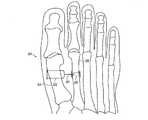
図1は、本発明の一実施形態により中足骨間角を小さくするための装置20が植え込まれた足の骨の概略上面図である。装置20は、第1中足骨24に植え込まれる第1のアンカー22と、第2中足骨28に植え込まれる第2のアンカー26とを備える。これらのアンカーは、アンカー間(したがって2つの中足骨間)に延びる可撓性のコード30によって連結される。以下で詳細に述べる調整機構により、外科医は、骨にアンカーを植え込んだ後、第1のアンカーと第2のアンカーの間に延びるコードの長さを調整することができる。したがって、外科医は、中足骨間距離、すなわち骨24と骨28のそれぞれの軸間の角度を意味するIMAを修正することができる。(Overview)
FIG. 1 is a schematic top view of a foot bone implanted with a
以下の説明では、説明をわかりやすくするために、「第1のアンカー」が第1中足骨に植え込まれ、一方「第2のアンカー」が第2中足骨に植え込まれると仮定する。しかし、代替実施形態では、これら2つのアンカーの機能および特徴のいくつかを交換することができる。したがって、本願および特許請求の範囲では、「第1」および「第2」という用語は、アンカーに関して任意に使用され、これらの用語が使用される特定の文脈で別段示されない限り、どのアンカーがどの骨に植え込まれることになるかを示してはいないことを理解されたい。 In the following description, for the sake of clarity, it is assumed that the “first anchor” is implanted in the first metatarsal bone while the “second anchor” is implanted in the second metatarsal bone. . However, in alternative embodiments, some of the functions and features of these two anchors can be exchanged. Thus, in this application and the claims, the terms “first” and “second” are used arbitrarily with respect to anchors, and unless otherwise indicated in the specific context in which these terms are used, It should be understood that it does not indicate what will be implanted in the bone.
本明細書に記載の装置および方法は特に中足骨、および外反母趾など諸状態の矯正に関するが、本発明の原理は、他の整形外科応用例において、特に隣接する骨間の間隔を修正するための治療において同様に応用することができる。たとえば、以下に記載の装置は、中手骨内の植込み用に修正することができる。可能な応用例の他の例は、直視下心臓手術後の胸骨骨切りの閉鎖、複数の骨折した肋骨を直ちに固定することを可能にする肋骨骨折の修復、肩鎖脱臼の整復、リスフラン骨折脱臼の治療を含む、尺側脱臼または腓骨脱臼した中手指節関節または中足指節関節の整復、足首靱帯損傷の治療、脊椎固定に対する代替としての隣接する椎骨の動的連結、扁平足の治療、槌趾の治療を含む。 Although the devices and methods described herein relate specifically to correcting conditions such as the metatarsal bone and hallux valgus, the principles of the present invention are particularly useful in other orthopedic applications to correct the spacing between adjacent bones. The same can be applied in the treatment of For example, the device described below can be modified for implantation in the metacarpal bone. Other examples of possible applications include closure of sternum osteotomy after open heart surgery, repair of fractures that allow multiple fractured ribs to be immediately fixed, reduction of shoulder chain dislocation, Lisfranc fracture dislocation Reduction of metacarpal or metatarsophalangeal joints that have undergone ankle or radial dislocation, treatment of ankle ligament damage, dynamic connection of adjacent vertebrae as an alternative to spinal fixation, treatment of flat feet, Includes acupuncture treatment.
(植込み型装置)
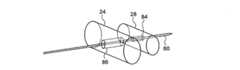
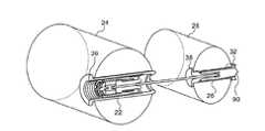
図2Aおよび図3は、本発明の一実施形態による装置20の詳細を概略的に示す。図2Aは、この装置の一部の外観の模式図であり、一方、図3は、断面図である。アンカー22、26は、316LVMタイプのステンレス鋼またはチタン合金など剛性の生体適合材料製であり、骨に穿設される円筒形の孔に挿入されるために円筒形の形状を有する。アンカー22の直径は、以下で述べる理由で一般にアンカー26の直径より大きい。たとえば、アンカー22は、長さ12mm、直径6mmであり、一方、アンカー26は、長さ11mm、直径3mmである。あるいは、とりわけアンカーが植え込まれることになる骨の寸法および状態に応じて、他の直径を選択してもよい。アンカー22、26は、ヒドロキシアパタイトなど骨成長促進因子で被覆されてもよい。(Implantable device)
2A and 3 schematically illustrate details of the
この実施形態におけるアンカー26は外ねじ34を有し、外ねじ34は、アンカーの遠位端35(すなわち、骨を通って挿入される端部)の上でナット32を受け入れ、また、アンカー26を骨それ自体に螺入するためにも使用することができる。アンカー22、26は、それらの近位端にそれぞれのカラー36、38を有し、カラー36、38は、これらのアンカーがそれぞれの孔に完全に挿入されたとき、骨の表面と係合する。次いで、ナット32がねじ山34上に締結され、アンカー26を骨内で定位置にしっかり固定する。(あるいは、下記図6に示されているように、スナップオン連結が使用されてもよい。) The
コード30は、足の骨によって、また足の骨に加えられる力に耐えるのに十分な強度の、任意の可撓性(しかし非弾性)の生体適合材料からなることができる。コードは、好適なポリマーまたは金属フィラメントの単一の糸または複数の糸からなることができる。たとえば、コード30は、約0.5mmの全体直径を有する、316LVMタイプのステンレス鋼ワイヤ製の編組ケーブルからなることができる。コード30は、ホルダ40によって、その近位端にヘッド41が取り付けられた状態で、アンカー22内に保持される。コード30は、たとえばコードの端部で結ばれた結び目39によって、または溶接によって、または他の任意の好適な締結の手段によって、ホルダおよびカラー38内で保持されてもよい。代替実施形態(図に示されていないが特許請求の範囲内にあると考えられる)では、アンカー22、26は、複数のコードによって連結されてもよく、これらのコードは、局部応力点を回避し取り除くために骨間である種の「ハンモック」として構成される。 The
ホルダ40はまた、ばね42を保持し圧縮する。ねじ48は、ホルダ40の位置を制御し、したがって圧縮の度合い、およびばね42に対する基本力を調整する。ねじ48は、より大きいねじ44内の内ねじに沿って移動する外ねじを有する。ねじ44は、アンカー22内の一致する内ねじ46に沿って移動する外ねじを有する。 The
ばね42は、コード30の張力を制御する。このばねは、典型的には、ステンレス鋼など弾性のある生体適合材料からなる。あるいは、装置20は、可撓性ポリマーもしくは粘弾性材料、移動中に機械力を加える磁気要素、または幾何学的移動に抗するように構成された空気式もしくは液圧式要素など、変形しながら機械抵抗を生み出す他の種類の機械的荷重要素を備えることができる。 The
ばね42の圧縮は、ねじ48の回転によって調整することができる(以下で詳細に述べる)。ねじ48を時計回りに回すことにより(ねじ山48が右手であると仮定)、ばねが圧縮され、対応する「ゼロ状態張力(zero−state tension)」がコード30内に生じる。たとえば、ゼロ状態張力は、約10ニュートンと15ニュートンの間の範囲内の値に設定することができるが、臨床状態に応じてより高い、またより低い張力の値を使用してもよい。 The compression of
アンカー22内のホルダ40の長手位置は、アンカー内の内ねじ46に沿って移動するねじ44を備える調整機構によって制御される。たとえば、ねじ44を反時計回りに回すことにより(ねじ山46が右手であると仮定)、ホルダ40が長手方向で近位方向にシフトし、したがってコード30をアンカー22内に引き込む。このようにして、アンカー間に延びるコードの長さが短縮され、それに応じて中足骨間角が小さくなる。あるいは、ねじ44を時計回りに回してコードを徐々に繰り出し、したがって中足骨間に加えられる力を低減することができる。 The longitudinal position of the
装置20内の調整機構は、外科医が、アンカーを植え込んだ後、中足骨間角を正確、容易かつ滑らかに制御することを可能にする。調整は、単純にねじ48を回すことによって行うことができ、当技術分野で知られている方法の場合のように縫合糸を手作業で適切な長さで結ぼうとする必要はない。さらに、アンカーの近位端でねじ48にアクセス可能な装置20の構成は、望むなら、外科医が後からコード30の長さを再調整することを可能にする。図の実施形態は、ねじをベースとする調整機構を具体的に示しており、この機構は、最初の植込みにも後続の調整にも有利であるが、代替として、クリップまたはスナップなど他のタイプの機構を使用してもよい。 The adjustment mechanism within the
ばね42は、コード30に加えられる力に応答して変形することによって緩衝器として働く。一般に歩行中には、中足骨24、28は、周期的に離れては戻るように移動する傾向があり、したがってコード30に周期的な力を加える。さらに、たとえば跳躍や蹴ることにより足が突然の衝撃を受けたとき、より強い力がコードに加えられることがある。これらの力は、アンカー22、26周りでコード30と骨を共に疲労させる可能性があり、最終的に装置20の故障、さらに悪いことには骨折を引き起こすおそれがある。ばね42は、これらの力の一部を吸収し、したがって装置故障および骨折から保護する助けとなる。 The
上記のように、外科医は、ねじ48の形態の力調整器により、ばね42の初期張力を調整することができる。このねじを回すと、ねじ48が同軸であるねじ44内の内ねじに沿って長手方向に移動する。ねじ48のこの長手方向運動により、コード・ホルダ40がばね42に対して圧迫または解放され、したがってばねの基本圧縮が増大または減少し、コード30に加えられる力に対するその応答が変わる。 As described above, the surgeon can adjust the initial tension of the
代替実施形態(図に示されていない)では、装置20内の緩衝器は、コード30に加えられる力に対して異なる応答をする2つ(又はそれ以上)の緩衝要素を備えることができる。たとえば、ばね42は、2つの部分を直列または並列で備えることができる。低いばね定数を有する第1の部分は、移動のある初期範囲にわたって小さい力を吸収する。この範囲を超えた後で、より高いばね定数を有するばねの第2の部分が、過剰な力を吸収する。この種の組合せ緩衝器は、患者の快適さを高め、装置の、また装置が植え込まれている骨の損傷の可能性を低減することができる。 In an alternative embodiment (not shown in the figure), the shock absorber in the
図2Bは、本発明の代替実施形態による植込み型装置内で使用するためのアンカー23の概略模式図である。アンカー23は、アンカー22と機能上同様であり、たとえばアンカー22の代わりに装置20内で使用することができる。アンカー23は、骨内に植え込まれたとき、骨24の表面と係合するカラー25を備える。カラー25は、骨に近接する組織に取り付けるために縫合糸(図示せず)を通すことができる1つまたは複数の穴27を含む。この縫合糸は、腱膜瘤の上でカプセルに通すことができ、したがってカプセルを近位に引き、装置20にアンカー固定することを可能にする。穴27に縫合針を通すのを容易にするために、穴27は、斜めの向きでカラーのリムに比較的近接して位置し、それによりカラーのリムと骨の間で針が滑るのを可能にする。 FIG. 2B is a schematic diagram of an
次に、本発明の一実施形態による、アンカー22内のコード調整機構および緩衝器がどのように調整されるかの詳細を示す図4および図5を図3と共に参照する。図4は、アンカー22の概略模式端面図である(図2および図3において左側に見えるアンカーの近位端を示す)。図5は、アンカー22、26が骨24、28内に植え込まれた後で調整を行うために好適に使用することができる外科的調整器具52の遠位端を示す概略模式図である。 Reference is now made to FIGS. 4 and 5 in conjunction with FIG. 3 showing details of how the cord adjustment mechanism and shock absorber in
調整手順を開始するために、器具52の固定先端54が、アンカー22内のヘッド41の中央ソケット50に挿入される。ヘッド41は、上記のようにコード・ホルダ40に連結される。図の実施形態では、ソケット50と先端54が共に方形であるが、他の一致する形状も同様に使用することができる。ソケット50および先端54の目的は、ねじ44、48が回されたとき、コード30の回転を防止することである。同様に、器具52の周囲の突起56は固定であり、カラー36内の凹部58と係合し、アンカー22が骨24内に植え込まれた後でその回転を防止する。 To begin the adjustment procedure, the fixed
ねじ48、44は、それぞれドライバ60、62を回すことによって、別々に独立して調整することができる。同軸であるこれらのドライバは、典型的には、器具52の近位端(図示せず)でそれぞれのノブまたはホイールによって制御される。ドライバ60上の凹部64がねじ48上の突起66と係合し、一方、ドライバ62上の突起68がねじ44上の凹部70と係合する。したがって、典型的な手順では、外科医は、器具52および先端54を回転させずに静止して保持し、一方、ばね42の所望の基本圧縮およびコード30のゼロ状態張力を、アンカー22とアンカー26の間におけるコード30の所望の長さと共に達成するために、ドライバ60とドライバ62のそれぞれを交代で回す。 The
代替実施形態では、器具52は、外科用キットの一部として提供され、インプラント20に取り付けられる。この実施形態では、先端54は、レーザ溶接など様々な手段によってソケット50に取り付けることができる。植込み後、器具52をインプラント20から取り外すために、先端54は、たとえば、手術者が手順の終わりに先端54を折り取ることによって器具52を容易に分離することができるように、先端の近位端付近に形成された溝55によって脆弱としておくことができる。 In an alternative embodiment,
図の実施形態では、器具52は、上述の機能すべてを実施する単一の包括的な器具として示されているが、代替として、これらの機能は、様々な調整機能を別々に実施するように構成された2つ以上の異なる器具によって実施されてもよい。 In the illustrated embodiment, the
図6は、本発明の代替実施形態による第1中足骨24および第2中足骨28内に植え込まれた外科的装置72の概略断面図である。装置72は、上述の装置20のように、アンカー74、76を備え、これらのアンカーは、それぞれ骨24、28内に植え込まれ、コード77によって連結される。装置72は、主に2つの点で装置20と異なる。
・アンカー76がスナップオン締結具78によって骨内で定位置に固定され、スナップオン締結具78は、アンカーが骨28を通って挿入された後、アンカー76の遠位端に取り付けられる。
・アンカー76内の内ねじが、コード77をアンカーに螺入および螺脱することを可能にし、それによりコード長調整機構の追加の一部として働く。FIG. 6 is a schematic cross-sectional view of a
-The internal thread in the
(手術方法)
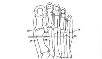
図7は、本発明の一実施形態による、装置20を使用して外反母趾を治療するための手順における準備段階を示す、足の概略上面図である。最初のステップとして、外科医は、位置29、すなわち第1中足の内側端部および第2中足の外側端部で切開を行うことができる。次いで、外科医は、第1中足骨24上の腱膜瘤から内側隆起(余分な組織)を除去することができ、第1中足骨から内転筋腱を切除することができ、それにより第1中足骨と第2中足骨を近づけることができるようにする。これらの外科的ステップは当技術分野で知られており、本特許出願の範囲外である。(Surgery method)
FIG. 7 is a schematic top view of a foot showing preparatory steps in a procedure for treating hallux
外科医は、最初に、手で、または専用クランプ(図示せず)など好適な器具を使用して、第2中足に向かって第1中足に力を加えることによって、第1中足骨24と第2中足骨28の間の距離を短縮する。このステップに続いて、外科医は、ドリル・ガイド(図示せず)を使用して、経皮的にKワイヤ80を第1中足骨24および第2中足骨28に突き通す。Kワイヤ径は、たとえば1.1mmとすることができる。次いで、外科医は、Kワイヤ80の上で、カニューレ型ドリル82を使用して骨24、28を通して穿孔する。本例では、ドリル82は、アンカー26の外径よりわずかに小さい2.8mmの直径を有する。 The surgeon first applies a force to the
図8〜図11は、本発明の一実施形態による、外科的処置における連続的な段階を示す骨24、28の概略模式図である。図8では、2.8mm孔84が第2中足骨28内に穿設されている。次いで、外科医は、より大きなドリル、たとえば直径6mmを使用し、第1中足骨24内により大きな孔86を生み出す。Kワイヤ80は、この段階でこれらの孔内に残っている。 8-11 are schematic diagrams of
アンカー22、26の挿入を助けるために、プラスチック・パイプまたはカニューレ型金属管(たとえば、316タイプのステンレス鋼(SU316)製)など、管88が外科的補助具として使用される。管88は、外科医による操作を容易にするために取り付けられたハンドル89、ならびにインプラント26の遠位端35に連結するためのクイックコネクト用の機構91を有することができる。機構91は、たとえば、遠位端35上の外ねじと対合する管88内の内ねじを備えることができる。 To assist in the insertion of the
図9に示されているように、外科医は、Kワイヤ80の上で、したがって孔84、86を通して管88を摺動し、次いで、機構91を使用して管88の遠位端をアンカー26に取り付ける。次に、外科医は、Kワイヤを遠位方向に(すなわち、図7に示されている図の右に)孔から引き出す。次いで、外科医は、管を遠位方向に引き、アンカー26、22を、アンカーがそれぞれ孔84、86内に完全に挿入されるまで孔86を通して交代で引く。外科医は、アンカー26を孔84内に螺入するために、引きながら管88を回すことができる。 As shown in FIG. 9, the surgeon slides the
代替実施形態では、管88は、たとえばレーザ溶接によって工場でインプラント26に予め取り付けておいてもよい。この場合、ハンドル89を遠位端管88の上で孔86から孔84まで引き、ねじノブ92によって管に固定することができる。他の点では、この手順は、上述のように実施される。 In an alternative embodiment, the
孔84、86内のアンカー26、22の最終位置が図10に示されている。カラー36、38が、近位側でそれぞれの骨24、28の表面と係合し、一方、ねじ山34および管88が、遠位側で孔84から外向きに突出する。アンカー26を定位置に固定するために、外科医は、図11に示されているように、ノブ92を使用して器具89を管88から緩め、器具89上にあるナット32を管88の上で摺動する。次いで、外科医は、骨28の遠位側と係合するように、器具89を使用してねじ山34の上でナットを締める。 The final position of the
図12は、本発明の一実施形態による、この手順における最終段階を示す概略断面図である。外科医は、好適な切断器具を使用して、第2中足骨28から遠位方向に突出するねじ山34の余分な部分を(連結された管88と共に)切断する。アンカー26は、短くなった端部90が遠位側で骨からわずかに突出する状態で残される。外科医は、上述(図4および図5)のように器具52を使用し、コード長およびばね基本変形を調整する。次いで、外科医は、切開を閉じ、手順を完了する。外科医は、骨に近接する組織に取り付けるために縫合糸を通し、したがってカプセルを近位に引き、装置20にアンカー固定することを可能にする穴27を使用することができる。 FIG. 12 is a schematic cross-sectional view showing the final stage in this procedure, according to one embodiment of the present invention. The surgeon uses a suitable cutting instrument to cut the excess portion of the thread 34 (along with the connected tube 88) protruding distally from the
図7〜図12は、装置20の植込みおよび調整のための特定の手順を示すが、代替の手術方法もまた使用することができ、本発明の範囲内にあるとみなされる。 7-12 illustrate specific procedures for implantation and adjustment of the
したがって、上述の実施形態は例として引用されていること、また本発明は上記で特に示され述べられているものに限定されないことを理解されたい。それどころか、本発明の範囲は、上記の様々な特徴の組合せおよびサブコンビネーションを共に含み、さらに前述の説明を読めば当業者に思い付くはずの、また従来技術で開示されていない本発明の変形形態および修正形態を含む。 Accordingly, it is to be understood that the above-described embodiments are cited by way of example and that the present invention is not limited to what has been particularly shown and described above. On the contrary, the scope of the present invention includes combinations and sub-combinations of the various features described above, and further variations of the present invention not disclosed in the prior art and which would occur to those skilled in the art upon reading the foregoing description and Includes modifications.
20、72 装置
22、23、26、74、76 アンカー
24、28 中足骨
25、36、38 カラー
27 穴
29 位置
30、77 コード
32 ナット
34 外ねじ
35 遠位端
39 結び目
40 ホルダ
41 ヘッド
42 ばね
44、48 ねじ
46 内ねじ
50 中央ソケット
52 器具
54 先端
55 溝
56 突起
58、64、70 凹部
60、62 ドライバ
66、68 突起
78 スナップオン締結具
80 Kワイヤ
82 ドリル
84、86 孔
88 管
89 ハンドル
91 機構
92 ねじノブ20, 72
Claims (11)
Translated fromJapanese前記第1の骨に隣接する第2の骨の内側に植え込まれるように構成された第2のアンカーと、
前記第1のアンカーと前記第2のアンカーの間に延びるコードと、
前記第1のアンカーおよび前記第2のアンカーの少なくとも一方に含まれ、前記コードに加えられる力に応答して変形するように前記コードに結合されたばね、並びに該ばねを圧縮することで該ばねの基本変形を調整する力調整器を備える緩衝器と、
調整機構と
を備え、
前記力調整器は、前記第1のアンカーの内部に含まれ前記ばねを保持すると共に圧縮するホルダの位置を制御する第1のねじを備え、
前記調整機構は、第2のねじに設けられた内ねじに沿って移動する外ねじを有する前記第1のねじと同軸であると共に前記第1のアンカーに設けられた内ねじに沿って移動する外ねじを有する当該第2のねじを備える植込み型装置。A first anchor configured to be implanted inside the first bone;
A second anchor configured to be implanted inside a second bone adjacent to the first bone;
A cord extending between the first anchor and the second anchor;
Aspring included in at least one of the first anchor and the second anchor and coupled to the cord to deform in response to a force applied to the cord; and the spring by compressing the spring a shock absorbercomprising a force regulator for adjusting the basicvariant,
Adjustment mechanism and
With
The force adjuster includes a first screw that is included inside the first anchor and controls the position of a holder that holds and compresses the spring;
The adjustment mechanism is coaxial with the first screw having an outer screw moving along an inner screw provided on a second screw and moves along an inner screw provided on the first anchor. An implantable device comprisingthe second screw having an external screw .
Applications Claiming Priority (3)
| Application Number | Priority Date | Filing Date | Title |
|---|---|---|---|
| US37795210P | 2010-08-29 | 2010-08-29 | |
| US61/377,952 | 2010-08-29 | ||
| PCT/IB2011/053763WO2012029008A1 (en) | 2010-08-29 | 2011-08-28 | Orthopedic implant for treatment of bone deformities |
Publications (2)
| Publication Number | Publication Date |
|---|---|
| JP2013539389A JP2013539389A (en) | 2013-10-24 |
| JP5822933B2true JP5822933B2 (en) | 2015-11-25 |
Family
ID=45772220
Family Applications (1)
| Application Number | Title | Priority Date | Filing Date |
|---|---|---|---|
| JP2013526577AActiveJP5822933B2 (en) | 2010-08-29 | 2011-08-28 | Orthopedic implants for treating bone deformities |
Country Status (7)
| Country | Link |
|---|---|
| US (2) | US9345514B2 (en) |
| EP (1) | EP2611371B1 (en) |
| JP (1) | JP5822933B2 (en) |
| AU (1) | AU2011298049B2 (en) |
| CA (1) | CA2842542C (en) |
| ES (1) | ES2633725T3 (en) |
| WO (1) | WO2012029008A1 (en) |
Families Citing this family (64)
| Publication number | Priority date | Publication date | Assignee | Title |
|---|---|---|---|---|
| US8696716B2 (en)* | 2007-08-02 | 2014-04-15 | Proactive Orthopedics, Llc | Fixation and alignment device and method used in orthopaedic surgery |
| US8882816B2 (en) | 2007-08-02 | 2014-11-11 | Proactive Orthopedics, Llc | Fixation and alignment device and method used in orthopaedic surgery |
| WO2010106507A2 (en) | 2009-03-17 | 2010-09-23 | Mor Research Applications Ltd | Hallux abducto valgus assemblies |
| JP5822933B2 (en) | 2010-08-29 | 2015-11-25 | ボンフィックス リミテッド | Orthopedic implants for treating bone deformities |
| US9101399B2 (en) | 2011-12-29 | 2015-08-11 | Proactive Orthopedics, Llc | Anchoring systems and methods for surgery |
| AU2013221935B2 (en)* | 2013-02-27 | 2018-07-05 | Bonfix Ltd. | Orthopedic Implant for Treatment of Bone Deformities |
| WO2014149934A1 (en)* | 2013-03-15 | 2014-09-25 | Moximed, Inc. | Structure and method for treating patello-femoral osteoarthritis |
| US20160038186A1 (en)* | 2013-03-15 | 2016-02-11 | Cycla Orthopedics Ltd. | Devices and methods for bone anchoring |
| US20160015426A1 (en) | 2014-07-15 | 2016-01-21 | Treace Medical Concepts, Inc. | Bone positioning and cutting system and method |
| WO2016044728A1 (en)* | 2014-09-18 | 2016-03-24 | Proception Medical, Llc | Fusion devices, systems and related methods |
| WO2016044053A1 (en)* | 2014-09-19 | 2016-03-24 | Crossroads Extremity Systems, Llc | Bone fixation implant and means of fixation |
| US9687250B2 (en) | 2015-01-07 | 2017-06-27 | Treace Medical Concepts, Inc. | Bone cutting guide systems and methods |
| EP3258868B1 (en)* | 2015-02-16 | 2019-08-21 | Akros Medical, Inc. | Devices and systems for semi-rigid bone fixation |
| WO2016134154A1 (en) | 2015-02-18 | 2016-08-25 | Treace Medical Concepts, Inc. | Pivotable bone cutting guide useful for bone realignment and compression techniques |
| US10653467B2 (en) | 2015-05-06 | 2020-05-19 | Treace Medical Concepts, Inc. | Intra-osseous plate system and method |
| US9622805B2 (en) | 2015-08-14 | 2017-04-18 | Treace Medical Concepts, Inc. | Bone positioning and preparing guide systems and methods |
| US10849663B2 (en) | 2015-07-14 | 2020-12-01 | Treace Medical Concepts, Inc. | Bone cutting guide systems and methods |
| EP4483824A3 (en) | 2015-07-14 | 2025-03-05 | Treace Medical Concepts, Inc. | Bone positioning guide |
| EP4494582A3 (en) | 2015-08-14 | 2025-04-16 | Treace Medical Concepts, Inc. | Tarsal-metatarsal joint procedure utilizing fulcrum |
| WO2017031020A1 (en) | 2015-08-14 | 2017-02-23 | Treace Medical Concepts, Inc. | Tarsal-metatarsal joint procedure utilizing fulcrum |
| CA2998481C (en) | 2015-09-18 | 2024-05-14 | Treace Medical Concepts, Inc. | Joint spacer systems and methods |
| EP3383281B1 (en) | 2015-12-04 | 2024-01-24 | Crossroads Extremity Systems, LLC | Devices for anchoring tissue |
| US10349996B2 (en) | 2015-12-07 | 2019-07-16 | Cable Fix LLC | Apparatus, system, and method for securing a tensioned cable through or around bone |
| US10172645B2 (en)* | 2016-05-20 | 2019-01-08 | Fastforward Surgical Inc. | Method of correcting hallux varus joint deformity |
| US9949774B2 (en) | 2016-05-26 | 2018-04-24 | Timothy Chen | Axial compression implant |
| US20180008286A1 (en) | 2016-07-05 | 2018-01-11 | Mortise Medical, LLC | Noncircular broach and methods of use |
| US10512470B1 (en) | 2016-08-26 | 2019-12-24 | Treace Medical Concepts, Inc. | Osteotomy procedure for correcting bone misalignment |
| US10524808B1 (en) | 2016-11-11 | 2020-01-07 | Treace Medical Concepts, Inc. | Devices and techniques for performing an osteotomy procedure on a first metatarsal to correct a bone misalignment |
| EP3357443B1 (en)* | 2017-02-03 | 2019-08-21 | Stryker European Holdings I, LLC | Tensioning cable locking device |
| US10939939B1 (en) | 2017-02-26 | 2021-03-09 | Treace Medical Concepts, Inc. | Fulcrum for tarsal-metatarsal joint procedure |
| US11179234B2 (en) | 2017-09-15 | 2021-11-23 | Paragon 28, Inc. | Ligament fixation system, implants, devices, and methods of use |
| US10925654B2 (en) | 2017-09-19 | 2021-02-23 | Cable Fix LLC | Apparatus, system, and method for crimping a cable for bone fixation |
| US10179016B1 (en)* | 2017-09-19 | 2019-01-15 | Cable Fix LLC | Apparatus, system, and method for crimping a cable for bone fixation |
| WO2019071273A1 (en) | 2017-10-06 | 2019-04-11 | Paragon 28, Inc. | Ligament fixation system, implants, devices, and methods of use |
| ES2955370T3 (en) | 2017-10-25 | 2023-11-30 | Paragon 28 Inc | Fixation system for ligaments, implants and devices with compression cap |
| US11596443B2 (en) | 2018-07-11 | 2023-03-07 | Treace Medical Concepts, Inc. | Compressor-distractor for angularly realigning bone portions |
| US11583323B2 (en) | 2018-07-12 | 2023-02-21 | Treace Medical Concepts, Inc. | Multi-diameter bone pin for installing and aligning bone fixation plate while minimizing bone damage |
| US11406399B2 (en)* | 2018-10-08 | 2022-08-09 | Conmed Corporation | Multi-barrel drill guide and anchor deployment assembly |
| US12295628B2 (en) | 2018-11-01 | 2025-05-13 | Howmedica Osteonics Corp. | Device for fixating orthopedic injury |
| US11607250B2 (en) | 2019-02-13 | 2023-03-21 | Treace Medical Concepts, Inc. | Tarsal-metatarsal joint procedure utilizing compressor-distractor and instrument providing sliding surface |
| EP3941363A4 (en)* | 2019-03-21 | 2022-12-07 | New York Society for the Relief of the Ruptured and Crippled, Maintaining the Hospital for Special Surgery | INTEROSSOUS COUPLER |
| WO2021021640A1 (en) | 2019-07-26 | 2021-02-04 | Crossroads Extremity Systems, Llc | Bone repositioning guide system and procedure |
| CA3146564A1 (en) | 2019-08-07 | 2021-02-11 | Jason May | Bi-planar instrument for bone cutting and joint realignment procedure |
| CA3153728A1 (en) | 2019-09-12 | 2021-03-18 | Paragon 28, Inc. | Dynamic fixation implant and method of use |
| US11889998B1 (en) | 2019-09-12 | 2024-02-06 | Treace Medical Concepts, Inc. | Surgical pin positioning lock |
| US11890039B1 (en) | 2019-09-13 | 2024-02-06 | Treace Medical Concepts, Inc. | Multi-diameter K-wire for orthopedic applications |
| US11986251B2 (en) | 2019-09-13 | 2024-05-21 | Treace Medical Concepts, Inc. | Patient-specific osteotomy instrumentation |
| WO2021155269A1 (en) | 2020-01-31 | 2021-08-05 | Treace Medical Concepts, Inc. | Metatarsophalangeal joint preparation and metatarsal realignment for fusion |
| AU2021275140A1 (en) | 2020-05-19 | 2023-02-02 | Treace Medical Concepts, Inc. | Devices and techniques for treating metatarsus adductus |
| US12161371B2 (en) | 2021-01-18 | 2024-12-10 | Treace Medical Concepts, Inc. | Contoured bone plate with locking screw for bone compression, particularly across a tarsometatarsal joint |
| US12310603B2 (en) | 2021-02-18 | 2025-05-27 | Treace Medical Concepts, Inc. | System and technique for metatarsal realignment with reduced incision length |
| AU2022276540A1 (en) | 2021-05-20 | 2023-11-30 | Treace Medical Concepts, Inc. | Cut guide with integrated joint realignment features |
| US11317956B1 (en) | 2021-08-26 | 2022-05-03 | University Of Utah Research Foundation | Active compression bone screw |
| JP7719312B2 (en)* | 2022-02-07 | 2025-08-05 | エクソームド コーポレーション | Systems and methods for CMC suture suspension arthroplasty |
| USD1079011S1 (en) | 2022-02-23 | 2025-06-10 | Treace Medical Concepts, Inc. | Metatarsal cut guide with parallel cut faces |
| USD1075012S1 (en) | 2022-02-23 | 2025-05-13 | Treace Medical Concepts, Inc. | Metatarsal lateral release instrument |
| USD1011524S1 (en) | 2022-02-23 | 2024-01-16 | Treace Medical Concepts, Inc. | Compressor-distractor for the foot |
| USD1051382S1 (en) | 2022-02-23 | 2024-11-12 | Treace Medical Concepts, Inc. | Lesser metatarsal cut guide |
| USD1057155S1 (en) | 2022-02-23 | 2025-01-07 | Treace Medical Concepts, Inc. | Lesser metatarsal cut guide with parallel cut faces |
| USD1068077S1 (en) | 2023-02-08 | 2025-03-25 | Treace Medical Concepts, Inc. | Orthopedic rasp for preparing an intercuneiform joint |
| USD1068078S1 (en) | 2023-02-08 | 2025-03-25 | Treace Medical Concepts, Inc. | Handle for an orthopedic instrument |
| US11998255B1 (en) | 2023-08-26 | 2024-06-04 | University Of Utah Research Foundation | Cannulated continuous compression screw |
| WO2025052370A1 (en)* | 2023-09-04 | 2025-03-13 | Bonfix Ltd. | Surgical tool and suture passing device and method |
| CN118490331B (en)* | 2024-07-18 | 2024-11-15 | 苏州爱得科技发展股份有限公司 | Hallux Correction Implant |
Family Cites Families (42)
| Publication number | Priority date | Publication date | Assignee | Title |
|---|---|---|---|---|
| US4159716A (en) | 1977-10-17 | 1979-07-03 | Borchers Clinton H | Method of compressing and realigning bone structures to correct splay foot |
| GB8622563D0 (en) | 1986-09-19 | 1986-10-22 | Amis A A | Artificial ligaments |
| US5366412A (en)* | 1992-05-19 | 1994-11-22 | Implant Innovations, Inc. | Torque limiting clutch and its uses |
| US5507812A (en)* | 1992-12-28 | 1996-04-16 | Moore; David E. | Modular prosthetic ligament |
| GB9306737D0 (en) | 1993-03-31 | 1993-05-26 | Surgicarft Ltd | Ligament augmentation device |
| US5529075A (en)* | 1994-09-12 | 1996-06-25 | Clark; David | Fixation device and method for repair of pronounced hallux valgus |
| FR2737968B1 (en)* | 1995-08-23 | 1997-12-05 | Biomat | IMPLANT FOR OSTEOSYNTHESIS OF SUPERIOR FEMALE EPIPHYSIS |
| NL1005394C1 (en)* | 1996-04-01 | 1997-10-02 | Kokbing Lo | Fixing element and strap fixed with fixing element. |
| BE1010569A6 (en)* | 1996-08-13 | 1998-10-06 | Dricot Roland | Prosthetic system to replace the anterior crossed ligament of the knee and semi-removable modular prosthesis of the anterior crossed ligament of the knee |
| US5941885A (en)* | 1996-10-08 | 1999-08-24 | Jackson; Roger P. | Tools for use in installing osteosynthesis apparatus utilizing set screw with break-off head |
| US6241732B1 (en) | 1998-11-03 | 2001-06-05 | David W. Overaker | Biocompatible absorbable rivets and pins for use in surgical procedures |
| US20050070906A1 (en)* | 1999-11-30 | 2005-03-31 | Ron Clark | Endosteal tibial ligament fixation with adjustable tensioning |
| US20050065533A1 (en)* | 2001-05-31 | 2005-03-24 | Magen Hugh E. | Apparatus for assembling anterior cruciate ligament reconstruction system |
| DE10129490A1 (en)* | 2001-06-21 | 2003-01-02 | Helmut Mueckter | Implantable screw for stabilization of joint or bone fracture, has flexible shaft which interconnects proximal head portion and distal insertion portion of elongated screw body |
| US7235091B2 (en) | 2002-06-20 | 2007-06-26 | Brian Thornes | Apparatus and method for fixation of ankle syndesmosis |
| US8828067B2 (en)* | 2001-10-18 | 2014-09-09 | Orthoip, Llc | Bone screw system and method |
| US6887275B2 (en) | 2001-12-15 | 2005-05-03 | Ace Surgical Supply Co., Inc. | Maxillofacial anchoring system for alveolar and small bone skeletal distraction |
| US7833255B2 (en)* | 2001-12-27 | 2010-11-16 | Osteotech, Inc. | Bone fasteners and method for stabilizing vertebral bone facets using the bone fasteners |
| US6629943B1 (en) | 2002-09-10 | 2003-10-07 | Mitchell J. Schroder | Bunion correction device |
| US20050149032A1 (en) | 2003-12-30 | 2005-07-07 | Douglas Vaughen | Resorbable surgical fixation device |
| US20060074422A1 (en) | 2004-09-27 | 2006-04-06 | Story Brooks J | Suture anchor and void filler combination |
| US8152837B2 (en)* | 2004-10-20 | 2012-04-10 | The Board Of Trustees Of The Leland Stanford Junior University | Systems and methods for posterior dynamic stabilization of the spine |
| NL1028292C2 (en)* | 2005-02-16 | 2006-08-17 | Kokbing Lo | Securing element for connecting a ligament to bone part, comprises ligament coupling element, clamping element having two parts with corresponding surfaces, stressing element and actuating element |
| US20060241608A1 (en) | 2005-03-31 | 2006-10-26 | Mark Myerson | Plate for fusion of the metatarso-phalangeal joint |
| US20070010818A1 (en) | 2005-07-06 | 2007-01-11 | Stone Howard A | Surgical system for joints |
| US20070185489A1 (en) | 2006-01-26 | 2007-08-09 | Abdou M S | Devices and Methods for Inter-Vertebral Orthopedic Device Placement |
| US7875058B2 (en)* | 2007-01-17 | 2011-01-25 | Arthrex, Inc. | Bunion repair using suture-button construct |
| US8715348B2 (en)* | 2007-04-25 | 2014-05-06 | Alaska Hand Research LLC | Method and device for stabilizing joints with limited axial movement |
| US8709090B2 (en)* | 2007-05-01 | 2014-04-29 | Moximed, Inc. | Adjustable absorber designs for implantable device |
| US20080275567A1 (en) | 2007-05-01 | 2008-11-06 | Exploramed Nc4, Inc. | Extra-Articular Implantable Mechanical Energy Absorbing Systems |
| US20090024147A1 (en) | 2007-07-18 | 2009-01-22 | Ralph James D | Implantable mesh for musculoskeletal trauma, orthopedic reconstruction and soft tissue repair |
| US8696716B2 (en)* | 2007-08-02 | 2014-04-15 | Proactive Orthopedics, Llc | Fixation and alignment device and method used in orthopaedic surgery |
| DE102008016607B4 (en)* | 2007-12-27 | 2020-10-29 | Mathys Ag Bettlach | Device for implantation in a bone and a system for stressing a reconstructed anterior cruciate ligament during the healing phase, comprising the device |
| CA2781407A1 (en) | 2008-01-14 | 2009-07-23 | Michael P. Brenzel | Apparatus and methods for fracture repair |
| US20090287246A1 (en)* | 2008-05-14 | 2009-11-19 | Depuy Mitek, Inc. | Knotless interface for threaded anchor |
| WO2010039969A2 (en) | 2008-10-01 | 2010-04-08 | Upex, Llc | Intramedullary tubular bone fixation |
| US8425554B2 (en) | 2008-12-16 | 2013-04-23 | Arthrex, Inc. | Suture passing K-wire |
| US8870876B2 (en) | 2009-02-13 | 2014-10-28 | Tarsus Medical Inc. | Methods and devices for treating hallux valgus |
| WO2010106507A2 (en) | 2009-03-17 | 2010-09-23 | Mor Research Applications Ltd | Hallux abducto valgus assemblies |
| DE102009051367B4 (en)* | 2009-04-28 | 2016-07-28 | Mathys Ag Bettlach | Implantable system with continuous dissolution mechanism during healing |
| US8696719B2 (en)* | 2010-06-03 | 2014-04-15 | Tarsus Medical Inc. | Methods and devices for treating hallux valgus |
| JP5822933B2 (en) | 2010-08-29 | 2015-11-25 | ボンフィックス リミテッド | Orthopedic implants for treating bone deformities |
- 2011
- 2011-08-28JPJP2013526577Apatent/JP5822933B2/enactiveActive
- 2011-08-28AUAU2011298049Apatent/AU2011298049B2/enactiveActive
- 2011-08-28WOPCT/IB2011/053763patent/WO2012029008A1/enactiveApplication Filing
- 2011-08-28ESES11821200.0Tpatent/ES2633725T3/enactiveActive
- 2011-08-28EPEP11821200.0Apatent/EP2611371B1/enactiveActive
- 2011-08-28CACA2842542Apatent/CA2842542C/enactiveActive
- 2013
- 2013-02-28USUS13/780,126patent/US9345514B2/enactiveActive
- 2016
- 2016-04-19USUS15/132,372patent/US10292735B2/enactiveActive
Also Published As
| Publication number | Publication date |
|---|---|
| US10292735B2 (en) | 2019-05-21 |
| ES2633725T3 (en) | 2017-09-25 |
| WO2012029008A1 (en) | 2012-03-08 |
| US20130184708A1 (en) | 2013-07-18 |
| JP2013539389A (en) | 2013-10-24 |
| EP2611371B1 (en) | 2017-04-05 |
| CA2842542A1 (en) | 2012-03-08 |
| US20160228152A1 (en) | 2016-08-11 |
| CA2842542C (en) | 2018-03-27 |
| EP2611371A4 (en) | 2014-09-24 |
| US9345514B2 (en) | 2016-05-24 |
| AU2011298049B2 (en) | 2016-02-18 |
| EP2611371A1 (en) | 2013-07-10 |
| AU2011298049A1 (en) | 2013-03-21 |
Similar Documents
| Publication | Publication Date | Title |
|---|---|---|
| JP5822933B2 (en) | Orthopedic implants for treating bone deformities | |
| EP1931287B1 (en) | Bone alignment implant | |
| US8652141B2 (en) | Methods and devices for treating hallux valgus | |
| US20150320451A1 (en) | Sacral fixation system | |
| US20160038186A1 (en) | Devices and methods for bone anchoring | |
| US20140228898A1 (en) | Universal method and apparatus for repairing bone, ligament and tendon | |
| CN111050675A (en) | Connectors for use in systems and methods for reducing proximal junctional kyphosis | |
| JP2020529248A (en) | Systems and methods for reducing the risk of proximal adjacent kyphosis deformity using bone anchors or other attachment points | |
| JP6338337B2 (en) | Orthopedic implantable device for treating bone deformation | |
| AU2013200038B2 (en) | Bone alignment implant and method of use |
Legal Events
| Date | Code | Title | Description |
|---|---|---|---|
| A621 | Written request for application examination | Free format text:JAPANESE INTERMEDIATE CODE: A621 Effective date:20140826 | |
| A131 | Notification of reasons for refusal | Free format text:JAPANESE INTERMEDIATE CODE: A131 Effective date:20150428 | |
| A977 | Report on retrieval | Free format text:JAPANESE INTERMEDIATE CODE: A971007 Effective date:20150430 | |
| A521 | Request for written amendment filed | Free format text:JAPANESE INTERMEDIATE CODE: A523 Effective date:20150724 | |
| TRDD | Decision of grant or rejection written | ||
| A01 | Written decision to grant a patent or to grant a registration (utility model) | Free format text:JAPANESE INTERMEDIATE CODE: A01 Effective date:20150908 | |
| A61 | First payment of annual fees (during grant procedure) | Free format text:JAPANESE INTERMEDIATE CODE: A61 Effective date:20151006 | |
| R150 | Certificate of patent or registration of utility model | Ref document number:5822933 Country of ref document:JP Free format text:JAPANESE INTERMEDIATE CODE: R150 | |
| R250 | Receipt of annual fees | Free format text:JAPANESE INTERMEDIATE CODE: R250 | |
| R250 | Receipt of annual fees | Free format text:JAPANESE INTERMEDIATE CODE: R250 | |
| R250 | Receipt of annual fees | Free format text:JAPANESE INTERMEDIATE CODE: R250 | |
| R250 | Receipt of annual fees | Free format text:JAPANESE INTERMEDIATE CODE: R250 | |
| R250 | Receipt of annual fees | Free format text:JAPANESE INTERMEDIATE CODE: R250 | |
| R250 | Receipt of annual fees | Free format text:JAPANESE INTERMEDIATE CODE: R250 | |
| R250 | Receipt of annual fees | Free format text:JAPANESE INTERMEDIATE CODE: R250 |