JP5820367B2 - Helical hybrid stent - Google Patents
Helical hybrid stentDownload PDFInfo
- Publication number
- JP5820367B2 JP5820367B2JP2012506597AJP2012506597AJP5820367B2JP 5820367 B2JP5820367 B2JP 5820367B2JP 2012506597 AJP2012506597 AJP 2012506597AJP 2012506597 AJP2012506597 AJP 2012506597AJP 5820367 B2JP5820367 B2JP 5820367B2
- Authority
- JP
- Japan
- Prior art keywords
- stent
- sideband
- endband
- stent component
- main stent
- Prior art date
- Legal status (The legal status is an assumption and is not a legal conclusion. Google has not performed a legal analysis and makes no representation as to the accuracy of the status listed.)
- Active
Links
- 238000004804windingMethods0.000claimsdescription32
- 229910000808amorphous metal alloyInorganic materials0.000claimsdescription23
- 239000000463materialSubstances0.000claimsdescription19
- 238000000034methodMethods0.000claimsdescription16
- 238000004873anchoringMethods0.000claimsdescription15
- 239000002184metalSubstances0.000claimsdescription13
- 229910052751metalInorganic materials0.000claimsdescription12
- 239000000956alloySubstances0.000claimsdescription9
- 229910045601alloyInorganic materials0.000claimsdescription8
- 239000003814drugSubstances0.000claimsdescription8
- 238000004519manufacturing processMethods0.000claimsdescription8
- XEEYBQQBJWHFJM-UHFFFAOYSA-NIronChemical compound[Fe]XEEYBQQBJWHFJM-UHFFFAOYSA-N0.000claimsdescription6
- 229910052796boronInorganic materials0.000claimsdescription5
- 239000000835fiberSubstances0.000claimsdescription5
- 229910052698phosphorusInorganic materials0.000claimsdescription5
- 229910052710siliconInorganic materials0.000claimsdescription5
- 239000010703siliconSubstances0.000claimsdescription5
- 229910052742ironInorganic materials0.000claimsdescription4
- 229940124597therapeutic agentDrugs0.000claimsdescription4
- ZOXJGFHDIHLPTG-UHFFFAOYSA-NBoronChemical compound[B]ZOXJGFHDIHLPTG-UHFFFAOYSA-N0.000claimsdescription3
- OAICVXFJPJFONN-UHFFFAOYSA-NPhosphorusChemical compound[P]OAICVXFJPJFONN-UHFFFAOYSA-N0.000claimsdescription3
- XUIMIQQOPSSXEZ-UHFFFAOYSA-NSiliconChemical compound[Si]XUIMIQQOPSSXEZ-UHFFFAOYSA-N0.000claimsdescription3
- 239000011574phosphorusSubstances0.000claimsdescription3
- 229920002635polyurethanePolymers0.000claimsdescription3
- 239000004814polyurethaneSubstances0.000claimsdescription3
- 229910052804chromiumInorganic materials0.000claimsdescription2
- 239000011148porous materialSubstances0.000claimsdescription2
- 238000004132cross linkingMethods0.000claims1
- 208000027418Wounds and injuryDiseases0.000description22
- 229920000642polymerPolymers0.000description14
- 230000008901benefitEffects0.000description7
- 238000003466weldingMethods0.000description6
- 238000002513implantationMethods0.000description5
- 229940079593drugDrugs0.000description4
- 238000009941weavingMethods0.000description4
- 229910000684Cobalt-chromeInorganic materials0.000description3
- 238000004026adhesive bondingMethods0.000description3
- 239000010952cobalt-chromeSubstances0.000description3
- 238000003618dip coatingMethods0.000description3
- 238000005304joiningMethods0.000description3
- 239000005300metallic glassSubstances0.000description3
- 238000005507sprayingMethods0.000description3
- WAIPAZQMEIHHTJ-UHFFFAOYSA-N[Cr].[Co]Chemical compound[Cr].[Co]WAIPAZQMEIHHTJ-UHFFFAOYSA-N0.000description2
- 238000005452bendingMethods0.000description2
- 239000000560biocompatible materialSubstances0.000description2
- 210000004204blood vesselAnatomy0.000description2
- 238000009954braidingMethods0.000description2
- 230000007797corrosionEffects0.000description2
- 238000005260corrosionMethods0.000description2
- 229920000295expanded polytetrafluoroethylenePolymers0.000description2
- 230000001788irregularEffects0.000description2
- 239000007769metal materialSubstances0.000description2
- 150000002739metalsChemical class0.000description2
- 229920001692polycarbonate urethanePolymers0.000description2
- 229920001296polysiloxanePolymers0.000description2
- ZAHRKKWIAAJSAO-UHFFFAOYSA-NrapamycinNatural productsCOCC(O)C(=C/C(C)C(=O)CC(OC(=O)C1CCCCN1C(=O)C(=O)C2(O)OC(CC(OC)C(=CC=CC=CC(C)CC(C)C(=O)C)C)CCC2C)C(C)CC3CCC(O)C(C3)OC)CZAHRKKWIAAJSAO-UHFFFAOYSA-N0.000description2
- 229960002930sirolimusDrugs0.000description2
- QFJCIRLUMZQUOT-HPLJOQBZSA-NsirolimusChemical compoundC1C[C@@H](O)[C@H](OC)C[C@@H]1C[C@@H](C)[C@H]1OC(=O)[C@@H]2CCCCN2C(=O)C(=O)[C@](O)(O2)[C@H](C)CC[C@H]2C[C@H](OC)/C(C)=C/C=C/C=C/[C@@H](C)C[C@@H](C)C(=O)[C@H](OC)[C@H](O)/C(C)=C/[C@@H](C)C(=O)C1QFJCIRLUMZQUOT-HPLJOQBZSA-N0.000description2
- 230000001360synchronised effectEffects0.000description2
- HKVAMNSJSFKALM-GKUWKFKPSA-NEverolimusChemical compoundC1C[C@@H](OCCO)[C@H](OC)C[C@@H]1C[C@@H](C)[C@H]1OC(=O)[C@@H]2CCCCN2C(=O)C(=O)[C@](O)(O2)[C@H](C)CC[C@H]2C[C@H](OC)/C(C)=C/C=C/C=C/[C@@H](C)C[C@@H](C)C(=O)[C@H](OC)[C@H](O)/C(C)=C/[C@@H](C)C(=O)C1HKVAMNSJSFKALM-GKUWKFKPSA-N0.000description1
- 208000031481Pathologic ConstrictionDiseases0.000description1
- 239000004952PolyamideSubstances0.000description1
- 229920002732PolyanhydridePolymers0.000description1
- 239000004698PolyethyleneSubstances0.000description1
- 239000004642PolyimideSubstances0.000description1
- 229920001710PolyorthoesterPolymers0.000description1
- 239000004721Polyphenylene oxideSubstances0.000description1
- 239000004372Polyvinyl alcoholSubstances0.000description1
- 229920006243acrylic copolymerPolymers0.000description1
- 239000000853adhesiveSubstances0.000description1
- 230000001070adhesive effectEffects0.000description1
- 229920000249biocompatible polymerPolymers0.000description1
- 230000015572biosynthetic processEffects0.000description1
- 230000004663cell proliferationEffects0.000description1
- 239000011651chromiumSubstances0.000description1
- 239000011248coating agentSubstances0.000description1
- 238000000576coating methodMethods0.000description1
- 230000006835compressionEffects0.000description1
- 238000007906compressionMethods0.000description1
- 239000012141concentrateSubstances0.000description1
- 238000010276constructionMethods0.000description1
- 229920001577copolymerPolymers0.000description1
- 230000006378damageEffects0.000description1
- 230000007547defectEffects0.000description1
- 229910003460diamondInorganic materials0.000description1
- 239000010432diamondSubstances0.000description1
- 230000005489elastic deformationEffects0.000description1
- 238000010828elutionMethods0.000description1
- 229960005167everolimusDrugs0.000description1
- 238000002347injectionMethods0.000description1
- 239000007924injectionSubstances0.000description1
- 208000014674injuryDiseases0.000description1
- 239000011159matrix materialSubstances0.000description1
- 229910001092metal group alloyInorganic materials0.000description1
- 229910001000nickel titaniumInorganic materials0.000description1
- 229910052755nonmetalInorganic materials0.000description1
- 150000002843nonmetalsChemical class0.000description1
- 230000002093peripheral effectEffects0.000description1
- 229920002627poly(phosphazenes)Polymers0.000description1
- 229920000058polyacrylatePolymers0.000description1
- 229920002647polyamidePolymers0.000description1
- 229920001610polycaprolactonePolymers0.000description1
- 229920000728polyesterPolymers0.000description1
- 229920000570polyetherPolymers0.000description1
- 229920000573polyethylenePolymers0.000description1
- -1polyethylenesPolymers0.000description1
- 229920001721polyimidePolymers0.000description1
- 239000002861polymer materialSubstances0.000description1
- 229920000098polyolefinPolymers0.000description1
- 229920002451polyvinyl alcoholPolymers0.000description1
- 230000002265preventionEffects0.000description1
- 230000000717retained effectEffects0.000description1
- 238000000926separation methodMethods0.000description1
- 239000010935stainless steelSubstances0.000description1
- 229910001220stainless steelInorganic materials0.000description1
- 230000036262stenosisEffects0.000description1
- 208000037804stenosisDiseases0.000description1
- 239000000126substanceSubstances0.000description1
- RCINICONZNJXQF-MZXODVADSA-NtaxolChemical compoundO([C@@H]1[C@@]2(C[C@@H](C(C)=C(C2(C)C)[C@H](C([C@]2(C)[C@@H](O)C[C@H]3OC[C@]3([C@H]21)OC(C)=O)=O)OC(=O)C)OC(=O)[C@H](O)[C@@H](NC(=O)C=1C=CC=CC=1)C=1C=CC=CC=1)O)C(=O)C1=CC=CC=C1RCINICONZNJXQF-MZXODVADSA-N0.000description1
- 230000001225therapeutic effectEffects0.000description1
- 230000037303wrinklesEffects0.000description1
Images


Classifications
- A—HUMAN NECESSITIES
- A61—MEDICAL OR VETERINARY SCIENCE; HYGIENE
- A61F—FILTERS IMPLANTABLE INTO BLOOD VESSELS; PROSTHESES; DEVICES PROVIDING PATENCY TO, OR PREVENTING COLLAPSING OF, TUBULAR STRUCTURES OF THE BODY, e.g. STENTS; ORTHOPAEDIC, NURSING OR CONTRACEPTIVE DEVICES; FOMENTATION; TREATMENT OR PROTECTION OF EYES OR EARS; BANDAGES, DRESSINGS OR ABSORBENT PADS; FIRST-AID KITS
- A61F2/00—Filters implantable into blood vessels; Prostheses, i.e. artificial substitutes or replacements for parts of the body; Appliances for connecting them with the body; Devices providing patency to, or preventing collapsing of, tubular structures of the body, e.g. stents
- A61F2/82—Devices providing patency to, or preventing collapsing of, tubular structures of the body, e.g. stents
- A61F2/86—Stents in a form characterised by the wire-like elements; Stents in the form characterised by a net-like or mesh-like structure
- A61F2/88—Stents in a form characterised by the wire-like elements; Stents in the form characterised by a net-like or mesh-like structure the wire-like elements formed as helical or spiral coils
- A—HUMAN NECESSITIES
- A61—MEDICAL OR VETERINARY SCIENCE; HYGIENE
- A61F—FILTERS IMPLANTABLE INTO BLOOD VESSELS; PROSTHESES; DEVICES PROVIDING PATENCY TO, OR PREVENTING COLLAPSING OF, TUBULAR STRUCTURES OF THE BODY, e.g. STENTS; ORTHOPAEDIC, NURSING OR CONTRACEPTIVE DEVICES; FOMENTATION; TREATMENT OR PROTECTION OF EYES OR EARS; BANDAGES, DRESSINGS OR ABSORBENT PADS; FIRST-AID KITS
- A61F2/00—Filters implantable into blood vessels; Prostheses, i.e. artificial substitutes or replacements for parts of the body; Appliances for connecting them with the body; Devices providing patency to, or preventing collapsing of, tubular structures of the body, e.g. stents
- A61F2/02—Prostheses implantable into the body
- A61F2/04—Hollow or tubular parts of organs, e.g. bladders, tracheae, bronchi or bile ducts
- A61F2/06—Blood vessels
- A61F2/07—Stent-grafts
- A—HUMAN NECESSITIES
- A61—MEDICAL OR VETERINARY SCIENCE; HYGIENE
- A61F—FILTERS IMPLANTABLE INTO BLOOD VESSELS; PROSTHESES; DEVICES PROVIDING PATENCY TO, OR PREVENTING COLLAPSING OF, TUBULAR STRUCTURES OF THE BODY, e.g. STENTS; ORTHOPAEDIC, NURSING OR CONTRACEPTIVE DEVICES; FOMENTATION; TREATMENT OR PROTECTION OF EYES OR EARS; BANDAGES, DRESSINGS OR ABSORBENT PADS; FIRST-AID KITS
- A61F2/00—Filters implantable into blood vessels; Prostheses, i.e. artificial substitutes or replacements for parts of the body; Appliances for connecting them with the body; Devices providing patency to, or preventing collapsing of, tubular structures of the body, e.g. stents
- A61F2/82—Devices providing patency to, or preventing collapsing of, tubular structures of the body, e.g. stents
- A61F2/86—Stents in a form characterised by the wire-like elements; Stents in the form characterised by a net-like or mesh-like structure
- A61F2/88—Stents in a form characterised by the wire-like elements; Stents in the form characterised by a net-like or mesh-like structure the wire-like elements formed as helical or spiral coils
- A61F2/885—Stents in a form characterised by the wire-like elements; Stents in the form characterised by a net-like or mesh-like structure the wire-like elements formed as helical or spiral coils comprising a coil including a plurality of spiral or helical sections with alternate directions around a central axis
- A—HUMAN NECESSITIES
- A61—MEDICAL OR VETERINARY SCIENCE; HYGIENE
- A61F—FILTERS IMPLANTABLE INTO BLOOD VESSELS; PROSTHESES; DEVICES PROVIDING PATENCY TO, OR PREVENTING COLLAPSING OF, TUBULAR STRUCTURES OF THE BODY, e.g. STENTS; ORTHOPAEDIC, NURSING OR CONTRACEPTIVE DEVICES; FOMENTATION; TREATMENT OR PROTECTION OF EYES OR EARS; BANDAGES, DRESSINGS OR ABSORBENT PADS; FIRST-AID KITS
- A61F2/00—Filters implantable into blood vessels; Prostheses, i.e. artificial substitutes or replacements for parts of the body; Appliances for connecting them with the body; Devices providing patency to, or preventing collapsing of, tubular structures of the body, e.g. stents
- A61F2/82—Devices providing patency to, or preventing collapsing of, tubular structures of the body, e.g. stents
- A61F2/86—Stents in a form characterised by the wire-like elements; Stents in the form characterised by a net-like or mesh-like structure
- A61F2/89—Stents in a form characterised by the wire-like elements; Stents in the form characterised by a net-like or mesh-like structure the wire-like elements comprising two or more adjacent rings flexibly connected by separate members
- A—HUMAN NECESSITIES
- A61—MEDICAL OR VETERINARY SCIENCE; HYGIENE
- A61F—FILTERS IMPLANTABLE INTO BLOOD VESSELS; PROSTHESES; DEVICES PROVIDING PATENCY TO, OR PREVENTING COLLAPSING OF, TUBULAR STRUCTURES OF THE BODY, e.g. STENTS; ORTHOPAEDIC, NURSING OR CONTRACEPTIVE DEVICES; FOMENTATION; TREATMENT OR PROTECTION OF EYES OR EARS; BANDAGES, DRESSINGS OR ABSORBENT PADS; FIRST-AID KITS
- A61F2/00—Filters implantable into blood vessels; Prostheses, i.e. artificial substitutes or replacements for parts of the body; Appliances for connecting them with the body; Devices providing patency to, or preventing collapsing of, tubular structures of the body, e.g. stents
- A61F2/82—Devices providing patency to, or preventing collapsing of, tubular structures of the body, e.g. stents
- A61F2/86—Stents in a form characterised by the wire-like elements; Stents in the form characterised by a net-like or mesh-like structure
- A61F2/90—Stents in a form characterised by the wire-like elements; Stents in the form characterised by a net-like or mesh-like structure characterised by a net-like or mesh-like structure
- A61F2/91—Stents in a form characterised by the wire-like elements; Stents in the form characterised by a net-like or mesh-like structure characterised by a net-like or mesh-like structure made from perforated sheets or tubes, e.g. perforated by laser cuts or etched holes
- A61F2/915—Stents in a form characterised by the wire-like elements; Stents in the form characterised by a net-like or mesh-like structure characterised by a net-like or mesh-like structure made from perforated sheets or tubes, e.g. perforated by laser cuts or etched holes with bands having a meander structure, adjacent bands being connected to each other
- A—HUMAN NECESSITIES
- A61—MEDICAL OR VETERINARY SCIENCE; HYGIENE
- A61K—PREPARATIONS FOR MEDICAL, DENTAL OR TOILETRY PURPOSES
- A61K31/00—Medicinal preparations containing organic active ingredients
- A61K31/33—Heterocyclic compounds
- A61K31/395—Heterocyclic compounds having nitrogen as a ring hetero atom, e.g. guanethidine or rifamycins
- A61K31/435—Heterocyclic compounds having nitrogen as a ring hetero atom, e.g. guanethidine or rifamycins having six-membered rings with one nitrogen as the only ring hetero atom
- A61K31/4353—Heterocyclic compounds having nitrogen as a ring hetero atom, e.g. guanethidine or rifamycins having six-membered rings with one nitrogen as the only ring hetero atom ortho- or peri-condensed with heterocyclic ring systems
- A61K31/436—Heterocyclic compounds having nitrogen as a ring hetero atom, e.g. guanethidine or rifamycins having six-membered rings with one nitrogen as the only ring hetero atom ortho- or peri-condensed with heterocyclic ring systems the heterocyclic ring system containing a six-membered ring having oxygen as a ring hetero atom, e.g. rapamycin
- A—HUMAN NECESSITIES
- A61—MEDICAL OR VETERINARY SCIENCE; HYGIENE
- A61L—METHODS OR APPARATUS FOR STERILISING MATERIALS OR OBJECTS IN GENERAL; DISINFECTION, STERILISATION OR DEODORISATION OF AIR; CHEMICAL ASPECTS OF BANDAGES, DRESSINGS, ABSORBENT PADS OR SURGICAL ARTICLES; MATERIALS FOR BANDAGES, DRESSINGS, ABSORBENT PADS OR SURGICAL ARTICLES
- A61L31/00—Materials for other surgical articles, e.g. stents, stent-grafts, shunts, surgical drapes, guide wires, materials for adhesion prevention, occluding devices, surgical gloves, tissue fixation devices
- A61L31/02—Inorganic materials
- A61L31/022—Metals or alloys
- A—HUMAN NECESSITIES
- A61—MEDICAL OR VETERINARY SCIENCE; HYGIENE
- A61L—METHODS OR APPARATUS FOR STERILISING MATERIALS OR OBJECTS IN GENERAL; DISINFECTION, STERILISATION OR DEODORISATION OF AIR; CHEMICAL ASPECTS OF BANDAGES, DRESSINGS, ABSORBENT PADS OR SURGICAL ARTICLES; MATERIALS FOR BANDAGES, DRESSINGS, ABSORBENT PADS OR SURGICAL ARTICLES
- A61L31/00—Materials for other surgical articles, e.g. stents, stent-grafts, shunts, surgical drapes, guide wires, materials for adhesion prevention, occluding devices, surgical gloves, tissue fixation devices
- A61L31/04—Macromolecular materials
- A61L31/048—Macromolecular materials obtained by reactions only involving carbon-to-carbon unsaturated bonds
- A—HUMAN NECESSITIES
- A61—MEDICAL OR VETERINARY SCIENCE; HYGIENE
- A61L—METHODS OR APPARATUS FOR STERILISING MATERIALS OR OBJECTS IN GENERAL; DISINFECTION, STERILISATION OR DEODORISATION OF AIR; CHEMICAL ASPECTS OF BANDAGES, DRESSINGS, ABSORBENT PADS OR SURGICAL ARTICLES; MATERIALS FOR BANDAGES, DRESSINGS, ABSORBENT PADS OR SURGICAL ARTICLES
- A61L31/00—Materials for other surgical articles, e.g. stents, stent-grafts, shunts, surgical drapes, guide wires, materials for adhesion prevention, occluding devices, surgical gloves, tissue fixation devices
- A61L31/04—Macromolecular materials
- A61L31/06—Macromolecular materials obtained otherwise than by reactions only involving carbon-to-carbon unsaturated bonds
- A—HUMAN NECESSITIES
- A61—MEDICAL OR VETERINARY SCIENCE; HYGIENE
- A61L—METHODS OR APPARATUS FOR STERILISING MATERIALS OR OBJECTS IN GENERAL; DISINFECTION, STERILISATION OR DEODORISATION OF AIR; CHEMICAL ASPECTS OF BANDAGES, DRESSINGS, ABSORBENT PADS OR SURGICAL ARTICLES; MATERIALS FOR BANDAGES, DRESSINGS, ABSORBENT PADS OR SURGICAL ARTICLES
- A61L31/00—Materials for other surgical articles, e.g. stents, stent-grafts, shunts, surgical drapes, guide wires, materials for adhesion prevention, occluding devices, surgical gloves, tissue fixation devices
- A61L31/08—Materials for coatings
- A61L31/10—Macromolecular materials
- A—HUMAN NECESSITIES
- A61—MEDICAL OR VETERINARY SCIENCE; HYGIENE
- A61L—METHODS OR APPARATUS FOR STERILISING MATERIALS OR OBJECTS IN GENERAL; DISINFECTION, STERILISATION OR DEODORISATION OF AIR; CHEMICAL ASPECTS OF BANDAGES, DRESSINGS, ABSORBENT PADS OR SURGICAL ARTICLES; MATERIALS FOR BANDAGES, DRESSINGS, ABSORBENT PADS OR SURGICAL ARTICLES
- A61L31/00—Materials for other surgical articles, e.g. stents, stent-grafts, shunts, surgical drapes, guide wires, materials for adhesion prevention, occluding devices, surgical gloves, tissue fixation devices
- A61L31/14—Materials characterised by their function or physical properties, e.g. injectable or lubricating compositions, shape-memory materials, surface modified materials
- A61L31/146—Porous materials, e.g. foams or sponges
- A—HUMAN NECESSITIES
- A61—MEDICAL OR VETERINARY SCIENCE; HYGIENE
- A61L—METHODS OR APPARATUS FOR STERILISING MATERIALS OR OBJECTS IN GENERAL; DISINFECTION, STERILISATION OR DEODORISATION OF AIR; CHEMICAL ASPECTS OF BANDAGES, DRESSINGS, ABSORBENT PADS OR SURGICAL ARTICLES; MATERIALS FOR BANDAGES, DRESSINGS, ABSORBENT PADS OR SURGICAL ARTICLES
- A61L31/00—Materials for other surgical articles, e.g. stents, stent-grafts, shunts, surgical drapes, guide wires, materials for adhesion prevention, occluding devices, surgical gloves, tissue fixation devices
- A61L31/14—Materials characterised by their function or physical properties, e.g. injectable or lubricating compositions, shape-memory materials, surface modified materials
- A61L31/16—Biologically active materials, e.g. therapeutic substances
- A—HUMAN NECESSITIES
- A61—MEDICAL OR VETERINARY SCIENCE; HYGIENE
- A61F—FILTERS IMPLANTABLE INTO BLOOD VESSELS; PROSTHESES; DEVICES PROVIDING PATENCY TO, OR PREVENTING COLLAPSING OF, TUBULAR STRUCTURES OF THE BODY, e.g. STENTS; ORTHOPAEDIC, NURSING OR CONTRACEPTIVE DEVICES; FOMENTATION; TREATMENT OR PROTECTION OF EYES OR EARS; BANDAGES, DRESSINGS OR ABSORBENT PADS; FIRST-AID KITS
- A61F2/00—Filters implantable into blood vessels; Prostheses, i.e. artificial substitutes or replacements for parts of the body; Appliances for connecting them with the body; Devices providing patency to, or preventing collapsing of, tubular structures of the body, e.g. stents
- A61F2/02—Prostheses implantable into the body
- A61F2/04—Hollow or tubular parts of organs, e.g. bladders, tracheae, bronchi or bile ducts
- A61F2/06—Blood vessels
- A61F2/07—Stent-grafts
- A61F2002/072—Encapsulated stents, e.g. wire or whole stent embedded in lining
- A—HUMAN NECESSITIES
- A61—MEDICAL OR VETERINARY SCIENCE; HYGIENE
- A61F—FILTERS IMPLANTABLE INTO BLOOD VESSELS; PROSTHESES; DEVICES PROVIDING PATENCY TO, OR PREVENTING COLLAPSING OF, TUBULAR STRUCTURES OF THE BODY, e.g. STENTS; ORTHOPAEDIC, NURSING OR CONTRACEPTIVE DEVICES; FOMENTATION; TREATMENT OR PROTECTION OF EYES OR EARS; BANDAGES, DRESSINGS OR ABSORBENT PADS; FIRST-AID KITS
- A61F2/00—Filters implantable into blood vessels; Prostheses, i.e. artificial substitutes or replacements for parts of the body; Appliances for connecting them with the body; Devices providing patency to, or preventing collapsing of, tubular structures of the body, e.g. stents
- A61F2/02—Prostheses implantable into the body
- A61F2/04—Hollow or tubular parts of organs, e.g. bladders, tracheae, bronchi or bile ducts
- A61F2/06—Blood vessels
- A61F2/07—Stent-grafts
- A61F2002/075—Stent-grafts the stent being loosely attached to the graft material, e.g. by stitching
- A—HUMAN NECESSITIES
- A61—MEDICAL OR VETERINARY SCIENCE; HYGIENE
- A61F—FILTERS IMPLANTABLE INTO BLOOD VESSELS; PROSTHESES; DEVICES PROVIDING PATENCY TO, OR PREVENTING COLLAPSING OF, TUBULAR STRUCTURES OF THE BODY, e.g. STENTS; ORTHOPAEDIC, NURSING OR CONTRACEPTIVE DEVICES; FOMENTATION; TREATMENT OR PROTECTION OF EYES OR EARS; BANDAGES, DRESSINGS OR ABSORBENT PADS; FIRST-AID KITS
- A61F2/00—Filters implantable into blood vessels; Prostheses, i.e. artificial substitutes or replacements for parts of the body; Appliances for connecting them with the body; Devices providing patency to, or preventing collapsing of, tubular structures of the body, e.g. stents
- A61F2/82—Devices providing patency to, or preventing collapsing of, tubular structures of the body, e.g. stents
- A61F2/86—Stents in a form characterised by the wire-like elements; Stents in the form characterised by a net-like or mesh-like structure
- A61F2/90—Stents in a form characterised by the wire-like elements; Stents in the form characterised by a net-like or mesh-like structure characterised by a net-like or mesh-like structure
- A61F2/91—Stents in a form characterised by the wire-like elements; Stents in the form characterised by a net-like or mesh-like structure characterised by a net-like or mesh-like structure made from perforated sheets or tubes, e.g. perforated by laser cuts or etched holes
- A61F2/915—Stents in a form characterised by the wire-like elements; Stents in the form characterised by a net-like or mesh-like structure characterised by a net-like or mesh-like structure made from perforated sheets or tubes, e.g. perforated by laser cuts or etched holes with bands having a meander structure, adjacent bands being connected to each other
- A61F2002/9155—Adjacent bands being connected to each other
- A61F2002/91583—Adjacent bands being connected to each other by a bridge, whereby at least one of its ends is connected along the length of a strut between two consecutive apices within a band
- A—HUMAN NECESSITIES
- A61—MEDICAL OR VETERINARY SCIENCE; HYGIENE
- A61F—FILTERS IMPLANTABLE INTO BLOOD VESSELS; PROSTHESES; DEVICES PROVIDING PATENCY TO, OR PREVENTING COLLAPSING OF, TUBULAR STRUCTURES OF THE BODY, e.g. STENTS; ORTHOPAEDIC, NURSING OR CONTRACEPTIVE DEVICES; FOMENTATION; TREATMENT OR PROTECTION OF EYES OR EARS; BANDAGES, DRESSINGS OR ABSORBENT PADS; FIRST-AID KITS
- A61F2220/00—Fixations or connections for prostheses classified in groups A61F2/00 - A61F2/26 or A61F2/82 or A61F9/00 or A61F11/00 or subgroups thereof
- A61F2220/0025—Connections or couplings between prosthetic parts, e.g. between modular parts; Connecting elements
- A61F2220/005—Connections or couplings between prosthetic parts, e.g. between modular parts; Connecting elements using adhesives
- A—HUMAN NECESSITIES
- A61—MEDICAL OR VETERINARY SCIENCE; HYGIENE
- A61F—FILTERS IMPLANTABLE INTO BLOOD VESSELS; PROSTHESES; DEVICES PROVIDING PATENCY TO, OR PREVENTING COLLAPSING OF, TUBULAR STRUCTURES OF THE BODY, e.g. STENTS; ORTHOPAEDIC, NURSING OR CONTRACEPTIVE DEVICES; FOMENTATION; TREATMENT OR PROTECTION OF EYES OR EARS; BANDAGES, DRESSINGS OR ABSORBENT PADS; FIRST-AID KITS
- A61F2220/00—Fixations or connections for prostheses classified in groups A61F2/00 - A61F2/26 or A61F2/82 or A61F9/00 or A61F11/00 or subgroups thereof
- A61F2220/0025—Connections or couplings between prosthetic parts, e.g. between modular parts; Connecting elements
- A61F2220/0058—Connections or couplings between prosthetic parts, e.g. between modular parts; Connecting elements soldered or brazed or welded
- A—HUMAN NECESSITIES
- A61—MEDICAL OR VETERINARY SCIENCE; HYGIENE
- A61F—FILTERS IMPLANTABLE INTO BLOOD VESSELS; PROSTHESES; DEVICES PROVIDING PATENCY TO, OR PREVENTING COLLAPSING OF, TUBULAR STRUCTURES OF THE BODY, e.g. STENTS; ORTHOPAEDIC, NURSING OR CONTRACEPTIVE DEVICES; FOMENTATION; TREATMENT OR PROTECTION OF EYES OR EARS; BANDAGES, DRESSINGS OR ABSORBENT PADS; FIRST-AID KITS
- A61F2230/00—Geometry of prostheses classified in groups A61F2/00 - A61F2/26 or A61F2/82 or A61F9/00 or A61F11/00 or subgroups thereof
- A61F2230/0063—Three-dimensional shapes
- A61F2230/0091—Three-dimensional shapes helically-coiled or spirally-coiled, i.e. having a 2-D spiral cross-section
- A—HUMAN NECESSITIES
- A61—MEDICAL OR VETERINARY SCIENCE; HYGIENE
- A61F—FILTERS IMPLANTABLE INTO BLOOD VESSELS; PROSTHESES; DEVICES PROVIDING PATENCY TO, OR PREVENTING COLLAPSING OF, TUBULAR STRUCTURES OF THE BODY, e.g. STENTS; ORTHOPAEDIC, NURSING OR CONTRACEPTIVE DEVICES; FOMENTATION; TREATMENT OR PROTECTION OF EYES OR EARS; BANDAGES, DRESSINGS OR ABSORBENT PADS; FIRST-AID KITS
- A61F2250/00—Special features of prostheses classified in groups A61F2/00 - A61F2/26 or A61F2/82 or A61F9/00 or A61F11/00 or subgroups thereof
- A61F2250/0058—Additional features; Implant or prostheses properties not otherwise provided for
- A61F2250/0067—Means for introducing or releasing pharmaceutical products into the body
- A61F2250/0068—Means for introducing or releasing pharmaceutical products into the body the pharmaceutical product being in a reservoir
- A—HUMAN NECESSITIES
- A61—MEDICAL OR VETERINARY SCIENCE; HYGIENE
- A61L—METHODS OR APPARATUS FOR STERILISING MATERIALS OR OBJECTS IN GENERAL; DISINFECTION, STERILISATION OR DEODORISATION OF AIR; CHEMICAL ASPECTS OF BANDAGES, DRESSINGS, ABSORBENT PADS OR SURGICAL ARTICLES; MATERIALS FOR BANDAGES, DRESSINGS, ABSORBENT PADS OR SURGICAL ARTICLES
- A61L2300/00—Biologically active materials used in bandages, wound dressings, absorbent pads or medical devices
- A61L2300/40—Biologically active materials used in bandages, wound dressings, absorbent pads or medical devices characterised by a specific therapeutic activity or mode of action
- A61L2300/416—Anti-neoplastic or anti-proliferative or anti-restenosis or anti-angiogenic agents, e.g. paclitaxel, sirolimus
- Y—GENERAL TAGGING OF NEW TECHNOLOGICAL DEVELOPMENTS; GENERAL TAGGING OF CROSS-SECTIONAL TECHNOLOGIES SPANNING OVER SEVERAL SECTIONS OF THE IPC; TECHNICAL SUBJECTS COVERED BY FORMER USPC CROSS-REFERENCE ART COLLECTIONS [XRACs] AND DIGESTS
- Y10—TECHNICAL SUBJECTS COVERED BY FORMER USPC
- Y10T—TECHNICAL SUBJECTS COVERED BY FORMER US CLASSIFICATION
- Y10T29/00—Metal working
- Y10T29/49—Method of mechanical manufacture
- Y10T29/49764—Method of mechanical manufacture with testing or indicating
Landscapes
- Health & Medical Sciences (AREA)
- Life Sciences & Earth Sciences (AREA)
- General Health & Medical Sciences (AREA)
- Veterinary Medicine (AREA)
- Public Health (AREA)
- Animal Behavior & Ethology (AREA)
- Engineering & Computer Science (AREA)
- Biomedical Technology (AREA)
- Heart & Thoracic Surgery (AREA)
- Vascular Medicine (AREA)
- Epidemiology (AREA)
- Oral & Maxillofacial Surgery (AREA)
- Cardiology (AREA)
- Transplantation (AREA)
- Surgery (AREA)
- Chemical & Material Sciences (AREA)
- Medicinal Chemistry (AREA)
- Physics & Mathematics (AREA)
- Optics & Photonics (AREA)
- Chemical Kinetics & Catalysis (AREA)
- Inorganic Chemistry (AREA)
- Molecular Biology (AREA)
- Dispersion Chemistry (AREA)
- Pharmacology & Pharmacy (AREA)
- Gastroenterology & Hepatology (AREA)
- Pulmonology (AREA)
- Media Introduction/Drainage Providing Device (AREA)
- Prostheses (AREA)
- Materials For Medical Uses (AREA)
- Polymers & Plastics (AREA)
- Organic Chemistry (AREA)
Description
Translated fromJapanese本出願は、2009年4月22日に出願された米国特許出願第12/428,347号明細書の利益を主張し、その出願の全内容を参照により援用する。 This application claims the benefit of US patent application Ser. No. 12 / 428,347, filed Apr. 22, 2009, the entire contents of which are incorporated by reference.
本発明は一般的にステントに関し、ステントは、血管等の体内の管腔を支持し、開通を保つために、又は管内のその他のエンドプロテーゼを固定及び支持するために、管腔の内部に移植される管腔内エンドプロテーゼデバイスである。 The present invention relates generally to stents, which are implanted within a lumen to support and remain open in a body lumen, such as a blood vessel, or to secure and support other endoprostheses in the tube. An endoluminal endoprosthesis device.
様々なステントが当技術分野で公知である。通常、ステントは管形状であるのが一般的であり、比較的小型の未拡張の径から拡張されたより大きな径に拡張可能である。移植のために、ステントは通常、カテーテルの末端に取り付けられており、当該ステントは比較的小型の未拡張の径の状態でカテーテルに保持される。カテーテルを用いて、未拡張のステントは、目標とする移植部位まで管腔を経由して到達する。ステントが目標とする移植部位に到達すると、当該ステントは通常バルーン又はステントを自己拡張させることにより拡張される。いずれの場合においても、拡張したステントは管腔が狭くなろうとする傾向に抵抗し、こうして管腔の開通性を維持する。 Various stents are known in the art. Typically, stents are generally tubular and can be expanded from a relatively small unexpanded diameter to a larger expanded diameter. For implantation, a stent is typically attached to the distal end of the catheter, and the stent is retained on the catheter in a relatively small unexpanded diameter. Using the catheter, the unexpanded stent reaches the target implantation site via the lumen. When the stent reaches the target implantation site, the stent is usually expanded by self-expanding the balloon or stent. In either case, the expanded stent resists the tendency to narrow the lumen, thus maintaining lumen patency.
ステントは金属製の管、又は平板シートから構成され得るが、平板シートはロール状にし、溶接、機械的な固定法、又は別の方法等により固定されてステントの管状構造を形成する。 The stent may be composed of a metal tube or a flat sheet, but the flat sheet is rolled and fixed by welding, a mechanical fixing method, another method, or the like to form a tubular structure of the stent.
ステントの設計に関連する特許のいくつかの例として、Palmazの米国特許第4,733,665号明細書、Gianturcoの米国特許第4,800,882号明細書及び同第5,282,824号明細書、Hillsteadの米国特許第4,856,516号明細書及び同第5,116,365号明細書、Wiktorの米国特許第4,886,062号明細書及び同第4,969,458号明細書、Pinchukの米国特許第5,019,090号明細書、Palmaz及びSchatzの米国特許第5,102,417号明細書、Wolffの米国特許第5,104,404号明細書、Towerの米国特許第5,161,547号明細書、Cardon et al.の米国特許第5,383,892号明細書、Pinchasik et al.の米国特許第5,449,373号明細書、及びIsrael et al.の米国特許第5,733,303号明細書が挙げられる。 Some examples of patents related to stent design include Palmaz US Pat. No. 4,733,665, Gianturco US Pat. Nos. 4,800,882 and 5,282,824. Description, Hillstead US Pat. Nos. 4,856,516 and 5,116,365, Wiktor US Pat. Nos. 4,886,062 and 4,969,458 US Pat. No. 5,019,090 to Pinchuk, US Pat. No. 5,102,417 to Palmaz and Schatz, US Pat. No. 5,104,404 to Wolff, US to Tower US Pat. No. 5,161,547, US Pat. No. 5,383,892 to Cardon et al., US Pat. No. 5,449,373 to Pinchasik et al., And Israel et al. U.S. Pat. No. 5,733,303 And the like.
ステントの一形態としてらせん状又はコイル状のステントが知られている。かかるステントの設計は、例えば米国特許第6,503,270号明細書及び同第6,355,059号明細書に記載されており、全体を本明細書において参照により援用する。かかるステント設計はらせん状ステントとして構成され、このステントでは、巻かれたセルのストリップからコイルが形成され、当該セルは一連の屈曲部を含む蛇行パターンを形成する。その他の類似したらせんコイル状のステント構造は当技術分野で公知である。 A spiral or coiled stent is known as one form of the stent. Such stent designs are described, for example, in US Pat. Nos. 6,503,270 and 6,355,059, the entirety of which is hereby incorporated by reference. Such a stent design is configured as a helical stent, in which a coil is formed from a strip of wound cells that form a serpentine pattern including a series of bends. Other similar helical coiled stent structures are known in the art.
従来のステント設計は、内腔をしっかりと支持できるようにステント拡張時に半径方向に対して十分な強度を確保することに重点が置かれている。しかし、半径方向に対して高い強度を有するステントは、ステントが移植される管腔よりも長さ方向に固い傾向も有する。ステントが移植される管腔よりも長さ方向に固いと、管腔のステントセクションと、ステントが存在しないセクションとの間で適合性に齟齬が生じること等から応力が集中するためステントの両端で管腔に傷害を与える頻度が増す可能性がある。さらに、ステントは、腔管が屈曲や伸長する本来の傾向を阻害する可能性がある。反対に、十分な可撓性を有するステントは、管腔壁に対する十分な、及び/又は均一な半径方向の支持力に欠ける場合が多い。従って、当技術分野では十分な半径方向の強度と高度な長さ方向の可撓性とがバランスしたステントについて継続的なニーズが存在する。 Conventional stent designs focus on ensuring sufficient strength in the radial direction when the stent is expanded so that the lumen can be firmly supported. However, stents with high radial strength also tend to be stiffer in the length direction than the lumen into which the stent is implanted. If the stent is stiffer in the length direction than the lumen in which it is implanted, stress will concentrate at the ends of the stent due to the fact that the compatibility between the stent section of the lumen and the section where the stent is not present will cause wrinkles. The frequency of injury to the lumen may increase. In addition, stents can hinder the natural tendency of the lumen to bend and stretch. Conversely, sufficiently flexible stents often lack sufficient and / or uniform radial support for the lumen wall. Accordingly, there is a continuing need in the art for stents that balance sufficient radial strength with a high degree of longitudinal flexibility.
当技術分野に存在する別の問題は、均一性のある高い可撓性と十分な半径方向の支持力とを有するステントを製造しつつ、コストを削減するためにステントの製造プロセスを単純化し、但し製造上の欠陥が生ずるのを防止しようとするときに生ずる。 Another problem that exists in the art is to simplify the stent manufacturing process to reduce costs while manufacturing stents with uniform and high flexibility and sufficient radial bearing force, However, it occurs when trying to prevent manufacturing defects.
本発明は、管腔の凹凸に適合し、留置後には管腔に均一な支持力を提供しつつ、屈曲した腔内に容易に追随することができるように長さ方向に可撓性のある、血管内で使用されるらせん状ステントを提供する。本発明のステントは主要ステント部品と第2のステント部品を含む。主要ステント部品は、金属又はアモルファス金属合金材料であり得る。アモルファス金属ステントの場合、当該ステントは、長さ方向の可撓性、反復する長さ方向の屈曲、圧迫、及びねじれに対する適合性と疲労抵抗性とを兼ね備えた従来型の金属製ステントの半径方向の支持力を有し、これら諸特性は金属ステントで実現可能な特性を上回ることができる。 The present invention conforms to the irregularities of the lumen and is flexible in the longitudinal direction so that it can easily follow the bent cavity while providing uniform support to the lumen after placement. Provide a helical stent for use in blood vessels. The stent of the present invention includes a main stent component and a second stent component. The main stent component can be a metal or amorphous metal alloy material. In the case of an amorphous metal stent, the stent is radial in a conventional metal stent that combines longitudinal flexibility, repeated longitudinal bending, compression, and torsional compatibility with fatigue resistance. These properties can exceed those achievable with metal stents.
ステントに形成する際には、主要ステント部品は、ステントの縦軸に対して斜めの角度でらせん巻状物の管状構造を形成する。らせん巻状物は少なくともステントの中央部分に沿って伸びている。各巻状物は隣り合う巻状物と空間的に隔たっていても、また隣り合う巻状物と近接してもよい。ステントの縦軸に沿った巻状物間の距離は、具体的なステントのニーズに応じて変化し得る。管状のステントを形成するためにらせん状に巻かれる前に、主要ステント部品は平板なリボン又はストリップであり、これは波形(例えば、正弦曲線又はジグザグ状)又はセルのパターン化されたバンド(例えば、六角形構造又はその他の幾何学的構造)により画定される。当該ストリップは、ステントの長さ方向に沿ってらせん状に巻く1又は2以上のサイドバンド、並びにサイドバンドに対してある角度で配置された、サイドバンドの一端又は両端から伸びるエンドバンドから構成される。エンドバンドは、形成されたステントの一端又は両端に、ステントの縦軸に対して直円柱を形成するように構成される。サイドバンド及びエンドバンドは、例えば、一般的に正弦曲線、ジグザグ、六角形、又はその他の幾何学的構造を有する部分を含むと理解される。 When formed into a stent, the main stent component forms a spiral wound tubular structure at an oblique angle with respect to the longitudinal axis of the stent. The spiral roll extends at least along the central portion of the stent. Each winding may be spatially separated from adjacent windings, or may be close to adjacent windings. The distance between the rolls along the longitudinal axis of the stent can vary depending on the needs of the particular stent. Prior to being helically wound to form a tubular stent, the primary stent component is a flat ribbon or strip, which can be corrugated (eg, sinusoidal or zigzag) or patterned bands of cells (eg, , Hexagonal structure or other geometric structure). The strip is composed of one or more sidebands spirally wound along the length of the stent, and endbands extending from one or both ends of the sidebands arranged at an angle to the sidebands. The The endband is configured to form a right circular cylinder at one or both ends of the formed stent relative to the longitudinal axis of the stent. Sidebands and endbands are understood to include portions having, for example, generally sinusoidal, zigzag, hexagonal, or other geometric structures.
本発明は、
1.管状構造を有するステントであって、
複数の巻状物、第1及び第2のサイドバンド並びに第1及び第2のエンドバンドを有するコイル状の主要ステント部品であって、前記サイドバンド及びエンドバンドのそれぞれが波形パターンを有し、前記第1及び第2のサイドバンドが途切れ途切れに(intermittently)接続され、前記エンドバンドが前記ステントの長さ方向の末端において直円柱を形成する、主要ステント部品と、
前記主要ステント部品の前記巻状物を相互接続する固定部と
を含む、ステント、
2.a)第1のエンドバンドが第1のサイドバンドに接続し、
b)第2のエンドバンドが第2のサイドバンドに接続し、
c)前記第1及び第2のサイドバンドがステントの縦軸に沿ってらせん状に巻かれ、前記第1のエンドバンドがステントの第1の末端において縦軸に対して第1の直円柱を形成し、前記第2のエンドバンドが前記ステントの第2の末端において前記ステントの縦軸に対して第2の直円柱を形成する、上記1に記載のステント、
3.波形を有する第1のサイドバンドと、
波形を有し、前記第1のサイドバンドに接続した第2のサイドバンドと、
波形、並びに第1の端部及び第2の端部により画定される長さを有する第1のエンドバンドであって、前記第1の端部と第2の端部との間の一点で前記第1のサイドバンドに接続し、前記第1のサイドバンドに対して斜めの角度で伸びている第1のエンドバンドと
を含む、主要ステント部品、
4.波形、第1の端部、及び第2の端部を有する第2のエンドバンドであって、第2のサイドバンドに接続し、前記第2のサイドバンドに対して斜めの角度で伸びている第2のエンドバンドをさらに含む、上記3に記載の主要ステント部品、
5.波形を有するサイドバンドと、
波形、第1の端部、及び第2の端部を有する第1のエンドバンドであって、1以上のクロスリンクにより前記サイドバンドに接続し、前記サイドバンドに対して斜めの角度で伸びている第1のエンドバンドと、
波形、第1の端部、及び第2の端部を有する第2のエンドバンドであって、1以上のクロスリンクにより前記サイドバンドに接続し、前記サイドバンドに対して斜めの角度で伸びている第2のエンドバンドと
を含む主要ステント部品、
6.1以上のサイドバンドが、1以上の開窓を有するストラットを含む、上記3〜5のいずれか一項に記載の主要ステント部品、
7.波形を有する第1のエンドバンドに1以上のクロスリンクにより接続した、波形を有するサイドバンドを含み、前記第1のエンドバンドが、前記サイドバンドの方向に対して斜めの角度で伸びており、
前記サイドバンド及びエンドバンドが、ループにより結合されたストラットの波形パターンを有し、1以上の前記ストラットが開窓を有し、前記ループが、前記開窓を有する前記ストラットの幅よりも狭い幅を有する、主要ステント部品、
8.サイドバンド及び第2のエンドバンドに接続された第2のサイドバンドをさらに含み、前記第2のエンドバンドが、前記第2のサイドバンドの方向に対して斜めの角度で伸びており、
前記第2のサイドバンド及び前記第2のエンドバンドが、ループにより結合されたストラットの波形パターンを有し、1以上の前記ストラットが開窓を有し、前記ループが、前記開窓を有する前記ストラットの幅よりも狭い幅を有する、上記7に記載の主要ステント部品、
9.開窓が治療薬で満たされている、上記6〜8のいずれか一項に記載の主要ステント部品、
10.波形パターンのいくつかの隣り合うストラットが、同一の長さを有する、上記7〜9のいずれか一項に記載の主要ステント部品、
11.上記1又は2に記載のステントの主要ステント部品の巻状物を相互接続する固定部であって、糸、ワイヤー、及びリボンからなる群から選択される構造物を含む、固定部、
12.主要ステント部品のらせん経路とは異なるらせん経路でステントの周りに巻かれる、上記11に記載の固定部、
13.ステントの全長にわたり、規則的に主要ステント部品と接続点において重なり合う、上記11又は12に記載の固定部、
14.繊維メッシュを含む、上記11〜13のいずれか一項に記載の固定部、
15.多孔性材料を含む、上記11〜14のいずれか一項に記載の固定部、
16.耐久性材料を含む、上記11〜15のいずれか一項に記載の固定部、
17.耐久性材料がポリウレタンである、上記16に記載の固定部、
18.らせん状の主要ステント部品の全長にわたり埋め込まれている、上記11〜17のいずれか一項に記載の固定部、
19.らせん状の主要ステント部品に末端で取り付けられている、上記11〜18のいずれか一項に記載の固定部、
20.金属を含む、上記3〜10のいずれか一項に記載の主要ステント部品、
21.金属の平板シートから切り出される、上記20に記載の主要ステント部品、
22.アモルファス金属合金を含む、上記3〜10、20、及び21のいずれか一項に記載の主要ステント部品、
23.アモルファス金属合金が、ケイ素、ホウ素、及びリンからなる群から選択される元素を含む、上記22に記載の主要ステント部品、
24.アモルファス金属合金が、Fe、Cr、B、及びPを含有する鉄基合金である、上記22に記載の主要ステント部品、
25.アモルファス金属合金がケイ素を含有する、上記22に記載の主要ステント部品、
26.アモルファス金属合金がFe−Cr−B−P合金を含む、上記22、23、及び25のいずれか一項に記載の主要ステント部品、
27.第1及び第2のサイドバンドが、少なくとも1つのクロスストラットにより接続されている、上記3、4、6、8〜10、及び20〜26のいずれか一項に記載の主要ステント部品、
28.少なくとも1つのクロスストラットがループを有する、上記27に記載の主要ステント部品、
29.第1のサイドバンドが、らせん状に隣り合った第2のサイドバンドに近接する、上記2に記載のステント、
30.上記1、2、及び29のいずれか一項に記載のステントを作製する方法であって、
a)縦軸に沿って主要ステント部品をらせん状に巻くステップと、
b)前記ステントの前記縦軸に対して直円柱が形成されるように、第1のエンドバンドの第1の端部を前記第1のエンドバンドの第2の端部と近接近させるステップと
を含む、方法、
31.縦軸に対して直円柱が形成されるように、第2のエンドバンドの第1の端部を前記第2のエンドバンドの第2の端部と近接近させるステップ
をさらに含む、上記30に記載の方法、
32.固定部を適用するステップをさらに含む、上記30又は31に記載の方法
に関する。The presentinvention,
1. A stent having a tubular structure,
A coiled main stent component having a plurality of windings, first and second sidebands and first and second endbands, each of the sidebands and endbands having a corrugated pattern; A primary stent component, wherein the first and second sidebands are connected intermittently, and the endband forms a right cylinder at the longitudinal end of the stent;
A securing portion interconnecting the windings of the main stent component;
Including a stent,
2. a) the first endband connects to the first sideband;
b) the second endband is connected to the second sideband;
c) the first and second sidebands are spirally wound along the longitudinal axis of the stent, and the first endband has a first right circular cylinder with respect to the longitudinal axis at the first end of the stent; The stent of claim 1, wherein the second endband forms a second right circular cylinder with respect to the longitudinal axis of the stent at the second end of the stent,
3. A first sideband having a waveform;
A second sideband having a waveform and connected to the first sideband;
A first endband having a corrugation and a length defined by a first end and a second end, wherein the first endband has a point between the first end and the second end; A first endband connected to the first sideband and extending at an oblique angle with respect to the first sideband;
Main stent parts, including
4). A second endband having a waveform, a first end, and a second end, connected to the second sideband and extending at an oblique angle with respect to the second sideband The main stent component of claim 3, further comprising a second endband,
5. A sideband having a waveform;
A first endband having a waveform, a first end, and a second end, connected to the sideband by one or more cross links and extending at an oblique angle with respect to the sideband A first endband having
A second endband having a waveform, a first end, and a second end, connected to the sideband by one or more cross links, and extending at an oblique angle with respect to the sideband With a second endband
Main stent parts including,
6. The main stent component according to any one of 3 to 5 above, wherein the one or more sidebands comprise struts having one or more fenestrations,
7). Including a corrugated sideband connected to the corrugated first endband by one or more cross links, wherein the first endband extends at an oblique angle with respect to the sideband direction;
The sidebands and endbands have strut corrugations connected by loops, one or more struts have fenestrations, and the loops are narrower than the struts having the fenestrations Having a major stent component,
8). A second sideband connected to the sideband and the second endband, wherein the second endband extends at an oblique angle with respect to the direction of the second sideband;
The second sideband and the second endband have a strut corrugated pattern joined by a loop, one or more of the struts have a fenestration, and the loop has the fenestrations The main stent component of claim 7, having a width that is narrower than the width of the struts;
9. Main stent component according to any one of claims 6 to 8, wherein the fenestration is filled with a therapeutic agent,
10. Main stent component according to any one of 7 to 9 above, wherein several adjacent struts of the corrugated pattern have the same length;
11. A fixing part for interconnecting windings of the main stent components of the stent according to 1 or 2 above, comprising a structure selected from the group consisting of a thread, a wire, and a ribbon,
12 The anchoring portion of claim 11, wherein the anchoring portion is wound around the stent in a spiral path different from the spiral path of the main stent component.
13. The fixing part according to 11 or 12 above, which regularly overlaps with the main stent component at the connection point over the entire length of the stent,
14 The fixing part according to any one of the above 11 to 13, including a fiber mesh,
15. The fixing part according to any one of the above 11 to 14, including a porous material,
16. The fixing part according to any one of the above 11 to 15, including a durable material,
17. The fixing part according to the above 16, wherein the durable material is polyurethane,
18. The fixing part according to any one of the above 11 to 17, which is embedded over the entire length of the helical main stent component,
19. The fixing part according to any one of the above 11 to 18, which is attached to the main spiral stent component at the end,
20. The main stent component according to any one of 3 to 10, comprising a metal,
21. The main stent component as described in 20 above, cut out from a flat metal sheet,
22. The main stent component according to any one of 3 to 10, 20, and 21, comprising an amorphous metal alloy,
23. The primary stent component of claim 22, wherein the amorphous metal alloy comprises an element selected from the group consisting of silicon, boron, and phosphorus;
24. The main stent component according to 22 above, wherein the amorphous metal alloy is an iron-based alloy containing Fe, Cr, B, and P;
25. The main stent component of claim 22, wherein the amorphous metal alloy contains silicon,
26. The main stent component according to any one of 22, 23, and 25, wherein the amorphous metal alloy comprises a Fe-Cr-BP alloy.
27. The main stent component according to any one of 3, 4, 6, 8-10, and 20-26, wherein the first and second sidebands are connected by at least one cross strut,
28. 28. The main stent component of claim 27, wherein at least one cross strut has a loop.
29. The stent according to 2 above, wherein the first sideband is adjacent to the spirally adjacent second sideband;
30. A method for producing the stent according to any one of the above 1, 2, and 29,
a) spirally winding the main stent component along the longitudinal axis;
b) bringing the first end of the first endband into close proximity with the second end of the first endband so that a right circular cylinder is formed with respect to the longitudinal axis of the stent;
Including, method,
31. Bringing the first end of the second endband into close proximity with the second end of the second endband so that a right circular cylinder is formed with respect to the longitudinal axis.
The method according to 30 above, further comprising:
32. 32. The method according to 30 or 31, further comprising applying a fixing part.
About .
別の実施形態では、主要ステント部品は、巻状物間の空間が最小限となるように、各らせん巻状物が、らせん構造物の隣り合うらせん巻状物と近接するように設計され得る。すなわち、サイドバンドリボンがステントの外周を斜め方向に移動すると、1つの巻状物が、隣り合った、実質的に類似した巻状物と近接する。このようにして、ステントのらせん巻状物は、全体的なステントの可撓性を損なうことなく管内の壁の被覆性を強化する。らせん巻状物は互いに直接触れることなく相互に近接することができるので、形成されたステントの全体的な可撓性は、らせんコイルの隣り合う巻状物が近接してもこれから影響を受けない。 In another embodiment, the main stent component may be designed such that each helical winding is in close proximity to the adjacent helical windings of the helical structure so that the space between the windings is minimized. . That is, as the sideband ribbon moves diagonally around the outer periphery of the stent, one winding is in close proximity to adjacent, substantially similar windings. In this way, the stent spiral increases the wall coverage within the tube without compromising the overall stent flexibility. Since the helical windings can be close to each other without directly touching each other, the overall flexibility of the formed stent is not affected by the proximity of adjacent windings of the helical coil. .
第2のステント部品、すなわち固定部は、長さ方向の可撓性に一役を担う一方、主要ステント部品の管形状を維持するように機能する。固定部は、ステントに構造的支持手段を提供する。固定部は、主要ステント部品をなおも管形状に維持したまま、主要ステント部品に対して、ステントが拡張又は屈曲した際には、固定部はステントの全体的な可撓性に寄与するように配置、固定される。固定部は、繊維、ワイヤー、糸、リボン、ストリップ、ポリマー、メッシュ等であり得る。 The second stent component, i.e. the anchor, serves to maintain the tube shape of the main stent component while playing a role in longitudinal flexibility. The anchor provides structural support for the stent. The anchoring portion is such that when the stent is expanded or bent relative to the main stent component, the anchoring portion contributes to the overall flexibility of the stent while still maintaining the main stent component in a tubular shape. Placed and fixed. The securing portion can be a fiber, wire, thread, ribbon, strip, polymer, mesh, or the like.
本発明は、らせん状ハイブリッドステントとして定義される、管腔内プロテーゼの新規クラスを提供する。以下でさらに説明されるように、本発明のステントは、らせん管状構造の形態にある主要ステント部品を含み、同部品は第2のステント部品、すなわち固定部により管形状に維持され得る。この主要ステント部品は、らせん状ステントを形成するようにらせん状に巻かれた、連続した波形の又はパターン化されたストリップから形成される。このストリップは、管状のらせん状ステント内に円筒状の環を形成する端面を有する。従って、本発明の一特徴は、ステントの両端に円筒状の環が隣接したらせん構造を有するステントの中央部本体である。中央部本体部分を形成するストリップはそれぞれ波形を有する1又は2以上のサイドバンドを備え、一方、端面は、波形を有する1又は2以上のエンドバンドを備える。各エンドバンドは、サイドバンドに対してオフセットした角度でサイドバンドと接続され、サイドバンド側に逆転して伸長し得る。サイドバンド及びエンドバンドの波形を形成するストラットの長さは、らせん巻状物に役立つように均一であっても、また変化してもよい。サイドバンド又はエンドバンドは、クロスストラットで互いに接続することもできる。クロスストラットの長さ及び形状はストリップの長さ全体を通じて変化し得るが、クロスストラットは1又は2以上のループを含むことができる。らせん状に巻かれたステントの波形は、均一な被覆を増強するために隣り合うらせん波形と近接することができる。主要ステント部品は、任意の従来の金属物質又はアモルファス金属合金から形成され得る。 The present invention provides a new class of endoluminal prostheses, defined as helical hybrid stents. As will be further described below, the stent of the present invention includes a main stent component in the form of a helical tubular structure, which can be maintained in a tubular shape by a second stent component, or anchor. The primary stent component is formed from a continuous corrugated or patterned strip that is spirally wound to form a helical stent. The strip has an end face that forms a cylindrical annulus within the tubular helical stent. Accordingly, one feature of the present invention is the central body of the stent having a helical structure with cylindrical rings adjacent to both ends of the stent. The strips forming the central body portion each comprise one or more sidebands having a corrugation, while the end face comprises one or more endbands having a corrugation. Each end band is connected to the side band at an angle that is offset with respect to the side band, and can be reversed and extended toward the side band. The length of the struts forming the sideband and endband corrugations may be uniform or variable to aid in the spiral winding. Sidebands or endbands can also be connected to each other with cross struts. Although the length and shape of the cross struts can vary throughout the length of the strip, the cross struts can include one or more loops. The spirally wound stent corrugations can be in close proximity to adjacent spiral corrugations to enhance uniform coverage. The main stent component can be formed from any conventional metallic material or amorphous metal alloy.
本明細書の新規らせん状ステントのいずれにおいても、主要ステント部品は、サイドバンド及び/又はエンドバンド内に、任意の適する形状及びサイズからなるフルの又は部分的な開窓を有するストラットも含み得る。開窓は、らせん状ステントの凹部内に臨床的有用性を有する治療薬を配置するのを可能にする。ステントは、開窓に好都合なように十分な幅のストラット、及び得られたステントが屈曲、拡張するのを容易にするのに十分小さな寸法の、ストラットと接続したループから構成され得る。 In any of the novel helical stents herein, the main stent component may also include struts having full or partial fenestrations of any suitable shape and size within the sideband and / or endband. . The fenestration makes it possible to place a therapeutic agent having clinical utility within the recess of the helical stent. The stent can be composed of a strut that is wide enough to facilitate fenestration and a loop connected to the strut that is small enough to facilitate bending and expansion of the resulting stent.
主要ステント部品は開窓又はネスリングの有無を問わず、別の発明の特徴、すなわち固定部により所定の位置に保持され得る。固定部は、接着手段、例えば、糊付け、ディップコーティング、スプレーコーティング等による結合も含めて、当技術分野で公知の様々な手段、例えば、溶接、接合、包埋、編込み、製織、圧接、結束、主要ステント部品と共に行われる鋳型への圧入又は注入のいずれかによって、主要ステント部品に固定されるポリマー、繊維、ワイヤー、糸、バンド、リボン、メッシュ、又はシートの任意の形態を含み得る。固定部は、円周方向、らせん方向、縦方向又はこれら以外の方向に配向可能であり、またステントが拡張又は屈曲した際には、当該固定部は、当該主要ステント部品をなおも管形状に保ちつつ、当該ステントの全体的な可撓性に役立つように、主要ステント部品の一部又は全部に固定され、又は埋め込まれ得る。 The main stent component, with or without fenestration or nesting, can be held in place by another inventive feature, i.e., a fixture. The fixing portion may be various means known in the art including bonding by adhesive means such as gluing, dip coating, spray coating, etc., for example, welding, joining, embedding, braiding, weaving, pressure welding, binding. It can include any form of polymer, fiber, wire, thread, band, ribbon, mesh, or sheet that is secured to the main stent component by either press fitting or injection into the mold performed with the main stent component. The anchoring portion can be oriented in the circumferential direction, spiral direction, longitudinal direction, or other directions, and when the stent is expanded or bent, the anchoring portion still causes the main stent component to become tubular. While being held, it can be fixed or embedded in some or all of the main stent components to help the overall flexibility of the stent.
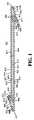
主要ステント部品は、当技術分野で公知の方法、又は本明細書に記載する方法を用いて、ストリップから形成され、パターン化され得る。図1は本明細書の実施形態を示し、この図では主要ステント部品はパターン化されたバンドとして形成されるが、非コイル状態、すなわち平板な形状で示されている。図1に示すように、リボンのパターンは、波形の第1のサイドバンド401と波形の第2のサイドバンド402とが相互接続することにより画定される1列のセル430を含む。また、エンドバンド406及び407は、サイドバンド401及び402に対して斜めの角度で伸びている。主要ステント部品は管形状に形成されるので、セル430の列は、ステントの縦軸の中央部分に沿った連続らせん巻状物となる一方、エンドバンド406及び407は、ステントの各末端で直円柱形状を形成する。このような方法で平板なパターン化されたバンドから、管状でらせん状の中央部本体部分を形成することは、設計が既存の管状材料から形成されるようなプロセスとは区別される。 The main stent component can be formed and patterned from a strip using methods known in the art or as described herein. FIG. 1 shows an embodiment of the present specification, in which the main stent component is formed as a patterned band, but is shown in a non-coiled, ie flat plate shape. As shown in FIG. 1, the ribbon pattern includes a row of
図1では、第1のサイドバンド401及び第2のサイドバンド402は概して平行方向に伸長するが、但し、第1のサイドバンドが第2のサイドバンドに向かって先細くなり、また第2のサイドバンドが第1のサイドバンドに向かって先細くなる、サイドバンドの一端を除く。図1に示すように、第1のサイドバンド401の波形パターンは、第2のサイドバンド402に向かって伸びているトラフ(例えば、410、411)、及び第2のサイドバンド402から遠ざかるピーク(例えば、414、415)を含む。同様に、第2のサイドバンド402の波形は、第1のサイドバンド401に向かって伸びているトラフ(例えば、412、413)、及び第1のサイドバンド401から遠ざかるピーク(例えば、416、417)を含む。このように、図1では、第1及び第2のサイドバンドは、互いに逆位相で配置している(トラフは実質的にトラフと同期する)。別の実施形態では、第1及び第2のサイドバンドはピークとトラフが実質的に同期するように同位相であり得る。 In FIG. 1, the
図1では、ピーク(416、417)及びトラフ(412、413)を画定するサイドバンドのストラットは、中央部ストリップ部分では実質的に等しい長さを有するが、サイドバンドが互いに向かって先細りになるに従い短めになる。図1の実施形態では、第1のサイドバンド401、及び第2のサイドバンド402は、複数の第1のクロスストラット403によって互いに接続され、セルの列を画定する。特に、第1のサイドバンド401の少なくとも1つのトラフ(例えば411)は、図1の第1のクロスストラット403を介して第2のサイドバンド402の対応するトラフ(例えば413)と接続している。従って、この実施形態では、一連のセルが形成され、各セル430は、隣り合うサイドバンドが結合することにより個別に画定されて、クロスストラットにより閉鎖した空間が形成される。例えば、中央部ストリップ部分のセルは、トラフ410及び411間の第1のサイドバンドの部分、トラフ412及び413間の第2のサイドバンドの部分、及びトラフ410と412及びトラフ411と413をそれぞれ接続する第1のクロスストラット403により画定される。 In FIG. 1, the sideband struts defining the peaks (416, 417) and troughs (412, 413) have substantially equal lengths in the central strip portion, but the sidebands taper toward each other. It becomes shorter according to. In the embodiment of FIG. 1, the
代替的実施形態では、第1のクロスストラット403の数、長さ、及び形状は、図1に示すものとは異なってもよい。例えば、第1のクロスストラット403は、第1のバンド401及び第2のバンド402を一定の間隔で、とりわけ、トラフ毎に、第2のトラフ毎に、第3のトラフ毎に、又は第4のトラフ毎等に接続することができ、これにより、より大きなセル、又は異なる幾何学特性を有するセルが形成される。また、クロスストラットは省略可能で、第1のサイドバンドは第2のサイドバンドに直接接続され得る。例えば、セル449は、ダイアモンド形の形状であり、第1及び第2のサイドバンドの波形によってのみ画定される。他の実施形態では、第1のクロスストラット403は第1のサイドバンド401、及び第2のサイドバンド402を、異なる、不規則な間隔で接続し得る。可変の、不規則な間隔で接続すると、連続した主要ステント部品に沿って、特定の用途にふさわしいと考えられるような様々な異なるサイズのセルを形成することができる。さらに、クロスストラットは第1のサイドバンドのピークと第2のサイドバンドのトラフ、又は第1のサイドバンドのトラフと第2のサイドバンドのピークを接続し得る。 In alternative embodiments, the number, length, and shape of the first cross struts 403 may be different from that shown in FIG. For example, the
第1のクロスストラット403は、図1に示すように、相互に比較して、サイドバンド401、402と比較して同一の幅をそれぞれ有し得る。或いは、第1のクロスストラット403は、特定の用途にふさわしいように第1及び第2のサイドバンド401、402とは異なる幅、又は互いに異なる幅を有し得る。クロスストラットは、第1及び第2のサイドバンド401、402の隣り合うトラフ又はオフセットトラフを接続し得る。さらに、第1のクロスストラット403は、直線状の部材を含み得、又は1つ若しくは2つ以上のループを含み得る。図1に示すように、異なるセル形状を有するステントが形成可能なように、異なる形状のクロスストラット又はクロスストラットを用いない方式も、ステントの特定の用途に応じて、単一ステント設計において代替的に採用可能である。典型的なセル形状は、米国特許第7,141,062号明細書(三角形のセル)、又は同第5,733,303号明細書(四角形のセル)に開示されており、四角形及び三角形のセル構造に関する開示を、本明細書において参考として上記特許から援用する。四角形のセルは半径方向に支持する要素の間に4箇所の接続部を有し、一方、三角形のセルは半径方向に支持する要素の間に3箇所の接続部を有する。サイド及びエンドバンドの波形は、本発明の半径方向に支持する要素を提供する。 As shown in FIG. 1, the first cross struts 403 may have the same width compared to the
図1に示す実施形態において、主要ステント部品400のサイドバンド401及び402は、各末端で先細りになっている。クロスストラット403の長さは、主要ステント部品400の各末端に向かって短くなっており、こうして第1及び第2のサイドバンド401、402は、より密接に配置し、最終的には接続部404及び405で直接接続している。短尺化したクロスストラットの代わりに、又はそれに加えて、サイドバンドは、波形中のストラットの長さを減じることにより互いに先細りとなり得る。 In the embodiment shown in FIG. 1, the
図1のサイドバンド401及び402の一端又は両端から伸びているのはエンドバンド406及び407である。従って、第1のエンドバンド406は、第1のサイドバンド401の一般的な方向からオフセットし、傾斜した方向に第1のサイドバンド401の末端から伸びている。図1では、ストリップを平置きしたときに第1のエンドバンドは、第1のサイドバンドの方向に対して45度未満の角度で第1のサイドバンドの方向に逆転して伸びている。第2のエンドバンド407は、第2のサイドバンド402の一般的な方向からオフセットし、傾斜した一般的な方向で、第1のエンドバンドと反対側に第2のサイドバンド402の末端から伸びている。図1では、ストリップを平置きしたときに第2のエンドバンドも、やはり第2のサイドバンドの方向に対して45度未満の角度で第2のサイドバンドの方向に逆転して伸びている。管状のステントを形成する際には、エンドバンド406及び407は、ステントの各末端で直円柱を形成するように構成され、ストリップのらせん巻状物の両端に隣接している。第1のエンドバンド406は第1の端部450及び第2の端部451を有する。管形状をとる時には、第1の端部450は第2の端部451と共に、ステントの縦軸に対して直円柱を形成するように移動する。第2のエンドバンド403は、第1の端部452及び第2の端部453を有する。管形状をとる時には、第1の端部452は第2の端部453と共に、ステントの縦軸に対して直円柱を形成するように移動する。以下でさらに説明されるように、端部450及び451は恒久的に接続することができ、或いは、固定部により所定の位置に保持可能であり、同部品はステントの縦軸に対して直円柱が形成されるように、2つの端部を近傍に保持可能である。 Extending from one or both ends of the
第1のエンドバンド406及び第2のエンドバンド407は、それぞれストラット及びループ又はターンを有する波形を含む。第1のエンドバンド406は、第1のサイドバンド401に向かって伸長するトラフ(例えば、418、419)、及び第1のサイドバンド401から遠ざかるピーク(例えば、422、423)を有する。同様に第2のエンドバンド407は、第2のサイドバンドに向かって伸長するトラフ(例えば、420、421)、及び第2のサイドバンド402から遠ざかるピーク(例えば、424、425)を有する。第1のエンドバンド406は、例えば、トラフ418のところで第1のサイドバンド401に直接接続しているが、第1のエンドバンド406は第1のサイドバンドから角度的に遠ざかるように伸びているので、第2のクロスストラット426は第1のエンドバンド406を第1のサイドバンド401と接続する。同様に、第2のエンドバンド407は、例えばトラフ420のところで第2のサイドバンド402と直接接続しているが、第2のエンドバンド407は第2のサイドバンドから角度的に遠ざかるように伸びているので、第2のクロスストラット426は第2のエンドバンド407を第2のサイドバンド402に接続する。図1に示すように、第2のクロスストラット426は、隣り合うエンドバンド及び/又はサイドバンドと共に接続点の間に1又は2以上のループを含み得る。第1のエンドバンド406及び第2のエンドバンド407のピークは、図1により示されるように、ピーク(例えば、423、424)から伸びる追加の環状構造を有していてもよい。 The
さらに、波形を有する第3のエンドバンド408は、第1のエンドバンド406に対して概して平行な位置関係で配置され、第3のエンドバンドのトラフ、例えば427は第1のエンドバンドに向かって伸び、また前記第1のエンドバンドに直接接続される。波形を有する第4のエンドバンド409は、第2のエンドバンド407に対して概して平行な位置関係で配置され、第4のエンドバンドのトラフ、例えば428は第2のエンドバンドに向かって伸びている。 In addition, a corrugated third endband 408 is disposed in a generally parallel relationship with respect to the
図2は、らせん状に巻かれて管状構造になった図1の主要ステント部品400を示す。主要ステント部品400内のセル430からなるストリップは、中央部分にらせん巻状物を形成し、同巻状物中では1つの巻状物内のある1つのセルは隣り合う巻状物のセルから長さ方向に空間的に隔たっている。第1のサイドバンド401及び第2のサイドバンド402は、クロスストラット403によって接続され、第1及び第2のサイドバンドがステントの縦軸に沿って交互に配置するように、ステントの縦軸の周りにらせん状に巻かれる。図2に示すようにらせん状に巻かれたステントでは、第1のサイドバンド401は、隣り合う第2のサイドバンド402と隣接し、クロスストラット403によって接続されるが、また隣り合う巻状物402”の第2のサイドバンドとも隣接し、この場合は接続されない。同様に、第2のサイドバンド402も、らせん状のステント内の長さ方向で隣り合う第1のサイドバンド401’とは接続されない。エンドバンド406及び407は、管状構造の両端を固定し、またステントの縦軸に対して実質的に直円柱状の環を形成する。空間、例えば431及び432は、隣り合う巻状物、例えば433、434、435の間に存在する。図2では、第1及び第2のサイドバンド401及び402は、クロスストラットが存在することにより、又は空間を有するらせん状ストリップの巻状物により互いに隔てられている。さらに、固定部は、以下で議論されるように、隣り合う巻状物の間の空間を保持し得る。 FIG. 2 shows the
図3は本発明の別の実施形態によるステントを示しており、らせん状のコイルの周期の間に長さ方向の空間がほとんど、又は実質的に存在しないようにらせん巻状物は配置されている。すなわち、図3が示すように、第1のらせん巻状物460のピーク(例えば、414、415)は、第2のらせん巻状物461のトラフ(例えば、412、413)に向かって近接している。一方、第1のサイドバンド401は第2のサイドバンド402に対して実質的に平行な状態のままである。同様に、第2のらせん巻状物461のピーク(例えば、416、417)は、第1のらせん巻状物460のトラフ(例えば、410、411)に向かって近接している。第1のサイドバンド401及び第2のサイドバンド402の間で直接的な接触が生じないように、近接するサイドバンドを配置するのが望ましいと考えられる。第1のサイドバンド401及び第2のサイドバンド402は、実質的に類似するが、反対の波形が整列するように配置されるので、第1のサイドバンド401及び第2のサイドバンド402は、形成されたステントの全長にわたり互いにこのような形で接近することができる。同一の長さのストラットを有するサイドバンドも近接するのに役立つ。このようにして、第1のサイドバンド401及び第2のサイドバンド402は、互いに近接するものとして説明され得る。図3では、第1及び第2のサイドバンド401及び402は、クロスストラットが存在することのみにより空間的に隔たっている。示す通り、近接する巻状物間の距離はクロスストラット403の長さよりも短い。さらに、第1のサイドバンド及び隣り合う第2のサイドバンドの間で直接的に接続することなく、第1のサイドバンドはらせん状で隣り合う第2のサイドバンドに向かって近接している。図3のステントは、以下でさらに議論するように、隣り合う巻状物が近接すると、ステントの可撓性を全く損なうことなく、管腔壁及び/又は固定部において支持されない領域が最小限に抑えられ、拡張した時に管内に固定部が垂れ下がるのを防止するという更なる利点を有する。さらに、らせん状のコイルが分離した状態で近接すると、管形状で構造を維持するのに役立ち得る。 FIG. 3 illustrates a stent according to another embodiment of the present invention, wherein the spiral winding is arranged so that there is little or substantially no longitudinal space between the periods of the helical coil. Yes. That is, as FIG. 3 shows, the peak (eg, 414, 415) of the
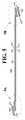
図4は代替的実施形態を表し、主要ステント部品1300は平板な形状、すなわち非コイル状態で提示されている。示す通り、主要ステント部品1300は、長さ方向にパターン化されたバンドを有する。図1の実施形態と同様に、図4の主要ステント部品1300の設計には、第1のサイドバンド1301、第2のサイドバンド1302、第1のエンドバンド1306、第2のエンドバンド1307、第3のエンドバンド1308、及び第4のエンドバンド1309が含まれる。管形状では、サイドバンド1301及び1302は、ステント本体の中央部分として連続したらせん巻状物を形成する一方、第1及び第2のエンドバンド1306及び1307は、ステントの末端環として、ステントの縦軸に対して直円柱を形成する。第1のエンドバンドでは、第1の端部1350は第2の端部1351と共に移動し、一方第2のエンドバンドでは、第1の端部1352は第2の端部1353と共に移動する。主要ステント部品1300は、治療物質を配置することができる1又は2以上の開窓を有するストラットを備える。 FIG. 4 represents an alternative embodiment in which the
各バンドは、例えば図4に示すように、1又は2以上の開窓を有するように十分な幅のストラットと共に形成される。主要ステント部品1300の有窓ストラットは、任意の幾何学的形状であり得、これには、円形、楕円形、又は長方形が含まれ、但しこれらに限定されない。さらに、開窓は、ストラットの厚さ全体に展開し得る(全面開窓)、又は部分的にのみ展開し得る(部分開窓)が、この場合にはストラットの一方の側のみが開口する(管形状の管腔側又は反管腔側)。また、ステントは、1つのストラット上で、又は異なるストラット間において異なるサイズ、数、及び形状を有する開窓を有するストラットも有し得る。本発明は、サイド及び/又はエンドバンドの一方又は両方に全面開窓及び/又は部分開窓を有するストラットを企図する。サイドバンドのピーク及びトラフを画定するストラットでは、得られたらせん状に巻かれたステント構造にとって望ましい形状をとりやすいように主要ステント部品の長さ方向に沿って長さが変化し、また開窓の数も変化し得る。例えば、図4Aではサイドバンドストラット1358及び1359は、エンドバンドストラット1356及び1357と同様に長さが異なる。有窓ストラットは、ループ又はターン1370により接続されており、その材料は、可撓性を高めるように有窓ストラットの材料よりも細めである。 Each band is formed with a strut that is sufficiently wide to have one or more fenestrations, for example as shown in FIG. The fenestrated struts of the
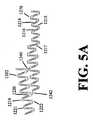
図5は、なおも本発明の別の実施形態を示し、主要ステント部品1200は平板な形状、すなわち非コイル状態で提示されている。示す通り、主要ステント部品1200は、平置きされたときには、長さ方向で単一のサイドバンド1201である。サイドバンド1201は、クロスストラット1240及び1241により、それぞれ第1のエンドバンド1202及び第2のエンドバンド1203に取り付けられている。サイドバンド1201は、同一又は異なる長さを有するストラットにより画定されるピーク(例えば、1210、1212)及びトラフ(例えば、1211、1213)が交互に入れ替わるパターンを含む。各サイド及びエンドバンドは、図4について上記したように、また図5にも適用可能なように、1又は2以上の全面開窓又は部分開窓を埋め込むのに十分な幅を有するストラットで形成される。有窓ストラットは、可撓性を高めるように有窓ストラットの材料よりも細めのループ又はターン1270により接続されている。図5Aに示すように、ストラットは長さが変化しており、また各ストラット内の開窓の数も異なる。例えば、ストラット1217は、ストラット1215とは異なる長さ及び開窓の数を有する。ストラット1216はストラット1215とは異なる長さを有するが、同一数の開窓を有する。並びに、ストラット1214及び1215は同一の長さ、及び開窓の数を有する。図5Aのステントでは、第1のサイドバンド1201の各末端の近傍のストラット(例えば、1217)は、ストラット1214及び1215とは異なる長さを有することができ、またらせん巻状物に役立つように構成される。 FIG. 5 still illustrates another embodiment of the present invention in which the main stent component 1200 is presented in a flat shape, ie, a non-coiled state. As shown, the main stent component 1200 is a
エンドバンド1202及び1203は、構造物を丸めてステントにしたときに周縁環を形成する。第1のエンドバンド1202及び第2のエンドバンド1203は、サイドバンド1201の一般的な方向から角度的にオフセットした方向にサイドバンド1201の各末端から伸びている。エンドバンド1202及び1203は、ステントの各末端で直円柱が形成されるように構成され、構造物を巻いてステントの状態にするときに中央部ステント本体のらせん巻状物に隣接する。第1のエンドバンド1202は、第1の端部1250及び第2の端部1251を有する。管形状では、第1の端部1250は第2の端部1251と共に移動して、ステントの縦軸に対して直円柱を形成する。第2のエンドバンド1203は、第1の端部1252及び第2の端部1253を有する。管形状では、第1の端部1252は第2の端部1253と共に移動して、ステントの縦軸に対して直円柱を形成する。以下でさらに説明するように、端部(1250及び1251;1252及び1253)は、恒久的に固定され得る、或いは、固定部により所定の位置に保持可能であり、同部品はステントの縦軸に対して直円柱を維持するように2つの端部を近傍に保持可能である。
図5Aでは、第1のエンドバンド1202は波形のバンドを備える。第1のエンドバンド1202の方向は、サイドバンド1201の方向に対してある角度でオフセットしている。図5Aでは、ステントを平置きにしたときに、サイドバンドから伸びている第1のエンドバンドは、ステントの中央部本体に対して45度未満の角度にある。第1のエンドバンド1202の波形パターンは、交互に入れ替わるピーク(例えば、1219、1221)及びトラフ(例えば、1220、1222)を含む。第1のエンドバンドのトラフ(1220、1222)はサイドバンドの方向に伸びているが、一方、ピーク(1219、1221)はサイドバンドから遠ざかる。第1のエンドバンド1202も開窓を有するストラットを含むことができる。図5Aでは、クロスリンク1240及び1242は、例えばサイドバンドを第1のエンドバンドに接続する。クロスリンク1240及び1242は、第1のエンドバンドのトラフからサイドバンドのピークに伸びている。サイドバンド及び第1のエンドバンドの間に伸びるクロスリンクは、1又は2以上の湾曲した部分を有する可撓性コネクタである。本発明は、クロスリンクが1又は2以上のループを含み得る実施形態についても企図する。 In FIG. 5A, the
図5Bでは、第2のエンドバンド1203も波形のバンドを含む。第2のエンドバンド1203の方向は、サイドバンド1201の方向に角度的にオフセットしている。好ましくは、ステントを平置きにしたときに、第2のエンドバンドはサイドバンドから45度未満の角度でステントの中央部本体に伸びている。第2のエンドバンド1203の波形パターンは、交互に入れ替わるピーク(例えば、1223、1225)及びトラフ(例えば、1224、1226)を含む。第2のエンドバンドのトラフ(1224、1226)は、サイドバンドの方向に伸びているが、一方、ピーク(1223、1225)はサイドバンドから遠ざかる。第2のエンドバンド1203は開窓を有するストラットを含む。図5Bでは、クロスリンク1241は、サイドバンドを第2のエンドバンドに接続する。クロスリンク1241は、第2のエンドバンドのトラフからサイドバンドのトラフに伸びている。サイドバンド及び第2のエンドバンドの間に伸びているクロスリンクは、1又は2以上の湾曲した部分を有する可撓性コネクタである。サイドバンドを第2のエンドバンドに接続するクロスリンクは、少なくとも1つのループを含み得る。 In FIG. 5B, the
さらに、本発明は、第1及び第2のエンドバンドに構成上類似したその他のエンドバンドであって、またらせん状に巻き、均一に被覆するのに好都合となるように第1又は第2のエンドバンドのいずれか一方に接続したその他のエンドバンドを企図する。図5Bでは、有窓ストラットを有する第3のエンドバンド1204が、クロスリンク1243により第2のエンドバンドに接続している。図5A及び5Bに示すように、本発明は、波形の又はパターン化されたサイドバンドに等しく接続していない、また互いに同一ではない第1及び第2のエンドバンドを企図する。サイドバンドと同様に、エンドバンドの任意の1つ又は全ては、有窓ストラットよりも細いゲージを有するループと共に接続された、1又は2以上の全面開窓又は部分開窓に好都合となるように十分に幅広いストラットを含み得る。 In addition, the present invention provides other endbands that are similar in construction to the first and second endbands, and can be wound in a helical fashion to facilitate uniform coating. Other endbands connected to either endband are contemplated. In FIG. 5B, a
主要ステント部品は、第2の部品により、らせん状に巻かれた位置に保持可能で、らせん巻状物を管状構造物に固定する。第2の部品は本明細書では固定部と呼び、これは主要ステント部品を管形状に固定するための1又は2以上の様々な手段であり得る。固定部は、中央部ステント本体のらせん巻状物、及び/又はエンドバンドにより直円柱の形成を維持する。一実施形態では、固定部は、繊維、シート、糸、又はリボンの形態の構造を含み、これらは、コイル状の主要ステント部品の中に包み込まれ、又はそれ自体が埋め込まれている。別の実施形態では、金属又は非金属材料で形成されたワイヤー又はリボンが、主要ステント部品が管状構成となるように維持する。この固定部は、当該固定部が破断したり剥離したりすることなく、らせん状の主要ステント部品が可撓性及び拡張性を有するのを可能にし、また主要ステント本体のコイル状の巻状物の間で、相対的に移動するのを可能にする材料を含む。そのような材料は、企図された構造物の具体的なニーズに応じて、連続又は不連続な状態で管状ステントに適用可能である。 The main stent component can be held in a helically wound position by the second component, securing the helical winding to the tubular structure. The second part is referred to herein as a fixation portion, which can be one or more various means for fixing the main stent part in a tubular shape. The fixed part maintains the formation of a right circular cylinder by the spiral wound and / or end band of the central stent body. In one embodiment, the anchoring portion comprises a structure in the form of a fiber, sheet, thread, or ribbon that is encased in or embedded in a coiled main stent component. In another embodiment, a wire or ribbon formed of a metallic or non-metallic material maintains the main stent component in a tubular configuration. This fixing portion allows the helical main stent component to be flexible and expandable without breaking or peeling off the fixing portion, and the coiled winding of the main stent body. Including materials that allow relative movement between the two. Such materials can be applied to the tubular stent in a continuous or discontinuous state, depending on the specific needs of the contemplated structure.
好ましくは、固定部は、移植中及び移植後に、弾性限界に達することなくステントが拡張し、また最大限屈曲するのを可能にする。弾性域は、特定のポリマーなどの使用材料における固有の弾性の結果、又は主要ステント部品との接続点間で非弾性材料にゆとりの長さが含まれることの結果である。固定部のなおも別の利点は、「ステントジェイル」現象の防止、又はステントによって覆われた側枝内へのトラッキングが複雑化することの防止である。更なる利点は、高い弾性域を有する特定の固定部構造では高い疲労抵抗性が得られることである。 Preferably, the anchoring portion allows the stent to expand and bend as much as possible without reaching the elastic limit during and after implantation. The elastic range is a result of the inherent elasticity of the material used, such as a particular polymer, or the result of the inelastic material including a length of clearance between the connection points with the main stent component. Yet another advantage of the anchoring is the prevention of the “stent jail” phenomenon or the complexity of tracking into the side branch covered by the stent. A further advantage is that high fatigue resistance is obtained with certain fixed part structures having a high elastic range.
一実施形態では、固定部は生体適合性の材料であるポリマーである。生体適合性材料は耐久性のある、例えば、ポリエステル、ポリアンヒドリド、ポリエチレン、ポリオルトエステル、ポリホスファゼン、ポリウレタン、ポリカーボネートウレタン、シリコーン、ポリオレフィン、ポリアミド、ポリカプロラクトン、ポリイミド、ポリビニルアルコール、アクリルポリマー及びコポリマー、ポリエーテル、セルロシックス、及び混合状態で、又はコポリマーとしてこれらを任意に組み合わせたものであり得る。特に有用なものとして、シリコーン骨格改変ポリカーボネートウレタン、及び/又は延伸ポリテトラフルオロエチレン(ePTFE,expanded polytetrafluoroethylene)であり得る。高弾性率(弾性域内の高伸長係数)を有する任意のポリマーが、固定部に特に適している。当該ポリマーは多孔性であってもよい。ポリマーが小さい繊維間距離を有する連続構造であるいくつかの実施形態では、当該ポリマーは薬物を溶出するためのマトリックスであってもよく、これによって均一な溶出ベッドを提供する。この種の多孔性の固定部は、その他の任意のステント構造に適用可能である。 In one embodiment, the anchoring portion is a polymer that is a biocompatible material. Biocompatible materials are durable, for example, polyesters, polyanhydrides, polyethylenes, polyorthoesters, polyphosphazenes, polyurethanes, polycarbonate urethanes, silicones, polyolefins, polyamides, polycaprolactones, polyimides, polyvinyl alcohol, acrylic polymers and copolymers, These may be any combination of polyether, cellulosic, and mixed or as a copolymer. Particularly useful may be silicone backbone modified polycarbonate urethanes and / or expanded polytetrafluoroethylene (ePTFE). Any polymer having a high modulus of elasticity (a high elongation coefficient in the elastic region) is particularly suitable for the fixing part. The polymer may be porous. In some embodiments where the polymer is a continuous structure with a small interfiber distance, the polymer may be a matrix for eluting the drug, thereby providing a uniform elution bed. This type of porous anchor is applicable to any other stent structure.
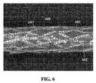
図6は、上記した図4のコイル状の主要ステント部品600を示し、多孔性で耐久性のあるポリマー固定部601が主要ステント部品600上に塗布されている。第1のサイドバンドの2つの隣り合うストラットは、「ディンプル」を備えたターン602により互いに接続されている。ターンにディンプルを含めることは、得られるステントの望ましい特性に応じた任意選択的な特徴である。図6は、ディンプルを有さない、また本実施形態においてクロスストラットが第1のサイドバンドを第2のサイドバンドに接続するポイントで採用されるターン603を示す。 FIG. 6 shows the coiled
図7では、らせん状の主要ステント部品500は、ポリマーシート701内に管状構造を埋め込むことにより固定され、そして図2に示す主要ステント部品のコイル状の一形態を示しており、すなわち、ステントの隣り合うらせん状のコイルは空間的に隔てられているが、ステントは埋め込まれたポリマー固定部により、そのらせん状の構造を維持している形態を示している。固定部は隙間内に配置され、及び/又はステント全体を通じて埋め込まれ得る。一実施形態では、ポリマーシートは、中央部分をらせん状の形態に、またエンドバンドを円柱状の形態に保つように、ステント構造の一部を固定し得る、又はステント全体を完全に包み込むことができる。 In FIG. 7, the helical
上記したように、ポリマーからなる固定部は、糸、ワイヤー、又はリボンの形態でも利用可能で、こうして主要ステント部品を、例えば一連の点を主要ステント部品と接続することにより固定する。1又は2以上の固定部としての糸、ワイヤー、又はリボンは、主要ステント部品とは異なるらせんの方向でステントにコイル状に巻かれていてもよい。特に、糸、ワイヤー、又はリボンは、らせん状に巻かれたストリップの方向とは逆向きのらせんでステントにコイル状に巻かれていてもよい。或いは、固定部はステントの縦軸に沿って配置され得る。主要ステント部品とは平行関係にない任意の方向で配置されると、それぞれの糸、ワイヤー、及びリボンは、ステントの全長にわたって規則的なパターンで主要ステント部品と重なり合うことができ、そしてらせん状のステントの本体構造を固定するのに効果的に機能し得る。固定部としての糸、ワイヤー、又はリボンは、接着手段、例えば、糊付け、ディップコーティング、スプレーコーティング等による結合も含め、様々な手段、例えば、溶接、接合、包埋、編込み、製織、圧接、結束、圧入等により、1又は2以上の重なり合った点で主要ステント部品に固定され得る。ポリマーからなる固定部は、ステントと共に、又はこれとは別に鋳型に注入することも可能であり、こうしてステント内で一体化した状態になる。糸、ワイヤー、又はリボンは、ステントの管形状を維持し、一方、上記で議論したポリマー材料の有する長さ方向に可撓な性質は、ステントの全体的な可撓性を高める。 As mentioned above, the anchoring part made of polymer can also be used in the form of a thread, wire or ribbon, thus fixing the main stent part, for example by connecting a series of points with the main stent part. The yarn, wire, or ribbon as one or more anchors may be coiled around the stent in a different spiral direction than the main stent component. In particular, the thread, wire, or ribbon may be coiled around the stent in a direction opposite to the direction of the spirally wound strip. Alternatively, the anchoring portion can be disposed along the longitudinal axis of the stent. When placed in any direction that is not parallel to the main stent component, each thread, wire, and ribbon can overlap the main stent component in a regular pattern over the entire length of the stent, and spiral It can function effectively to secure the body structure of the stent. Yarns, wires, or ribbons as fixing parts can be bonded by various means, including bonding by gluing, dip coating, spray coating, etc., for example, welding, joining, embedding, braiding, weaving, pressure welding, It can be secured to the main stent component at one or more overlapping points by binding, press fitting or the like. The fixing part made of a polymer can be injected into the mold together with or separately from the stent, and is thus integrated in the stent. The yarn, wire, or ribbon maintains the stent's tubular shape, while the longitudinally flexible nature of the polymer material discussed above increases the overall flexibility of the stent.
図8は、らせん状に巻かれたステントを示しており、主要ステント部品800は、2つのリボン801により所定の位置に固定されたらせん状に巻かれた管状構造を形成する。リボン801は、ステントの長さ方向に沿って伸びるポリマー材料である。リボンはステントの外面又は内面に固定可能で、又はらせん状に巻かれた主要ステント部品の中に埋め込まれ得る。図8では、主要ステント部品800は、主要ステント部品800と第2の部品であるリボン801のそれぞれとが交差する点で、各リボン801の中に埋め込まれている。 FIG. 8 shows a spiral wound stent, where the main stent component 800 forms a spiral wound tubular structure that is secured in place by two ribbons 801. Ribbon 801 is a polymeric material that extends along the length of the stent. The ribbon can be secured to the outer or inner surface of the stent, or it can be embedded in a spirally wound main stent component. In FIG. 8, the main stent component 800 is embedded in each ribbon 801 at the point where the main stent component 800 and each of the second component ribbons 801 intersect.
図9は、らせん状に巻かれたステントを示しており、主要ステント部品1000は図2に類似した管状構造を形成し、また1又は2以上の固定部としてのワイヤー1001は、コイル状に巻かれたステント中央部本体部分の方向とは異なるらせん方向で巻かれている。固定部としてのワイヤー1001は、ステントに沿った接続部1002の様々な点において主要ステント部品1000に固定されており、こうしてらせん状の管状構造を維持している。 FIG. 9 shows a spiral wound stent, where the main stent component 1000 forms a tubular structure similar to FIG. 2 and the wire 1001 as one or more anchors is coiled. It is wound in a spiral direction that is different from the direction of the main body portion of the stent. The wire 1001 as the anchor is secured to the main stent component 1000 at various points in the connection 1002 along the stent, thus maintaining a helical tubular structure.
ポリマーからなる固定部に加えて、金属及び/又は非金属を含む任意のその他の適する材料が、糸、ワイヤー、又はリボンの形態の固定部として、主要ステント部品を固定するのに利用可能である。金属又は非金属製の固定部としてのワイヤー、糸、又はリボンは、上記で明らかにしたような1又は2以上の様々な手段により、これらが重なり合う箇所で主要ステント部品に固定可能である。第2の部品を製造するために採用された材料が、望んだよりも長さ方向の可撓性に劣る場合には、接続点の間の糸、ワイヤー、又はリボンの長さを増加させることにより、可撓性を高めることができ、こうすることでステントが拡張又は屈曲した時に伸長可能な長さのゆとりが第2の部品に確保される。 In addition to polymeric anchors, any other suitable material including metals and / or non-metals can be used to anchor the main stent component as anchors in the form of threads, wires, or ribbons. . A wire, thread, or ribbon as a metal or non-metallic anchor can be secured to the main stent component at the point where they overlap by one or more of various means as set forth above. Increase the length of the thread, wire, or ribbon between the connection points if the material employed to manufacture the second part is less flexible in the longitudinal direction than desired. Thus, the flexibility can be increased, and in this way, the second component is secured with a length that can be extended when the stent is expanded or bent.
主要ステント部品がアモルファス金属合金であるいくつかの実施形態では、更なる利点が得られる、すなわち、腐食抵抗性、望ましくない恒久的な変形に対する抵抗性が向上し、及び/又は所定の金属の厚さに対する強度が高まる。また、アモルファス金属合金を含む本発明のステントは、結晶性又は多結晶性のこれらの相当物と比較して顕著に低い導電性も示し、又は非導電性である。かかる合金では、引張強度、弾性変形特性が向上し、デバイスに対して腐食をもたらす可能性が低減し得る。体内で繰り返し変形を受け、疲労にさらされるデバイスについて疲労抵抗性のある延長した寿命を実現するのに、これらは医療デバイスにおいて重要な特徴である。さらに、これらの特徴は、嵩高い従来型の相当物と強度は同じだが、より小型又は薄型のデバイスの製造を可能にする。 In some embodiments where the primary stent component is an amorphous metal alloy, additional advantages are obtained, i.e., increased resistance to corrosion, resistance to undesirable permanent deformation, and / or a given metal thickness. Increases strength against thickness. The stents of the present invention comprising amorphous metal alloys also exhibit significantly lower conductivity compared to their crystalline or polycrystalline equivalents or are non-conductive. Such alloys can improve tensile strength, elastic deformation characteristics, and reduce the possibility of corrosion to the device. These are important features in medical devices in order to achieve a fatigue-resistant extended life for devices that are subject to repeated deformation and exposure in the body. Furthermore, these features are similar in strength to the bulky conventional counterparts, but allow for the production of smaller or thinner devices.
別の実施形態では、主要ステント部品のアモルファス金属合金は半金属であってもよく、その非限定的な例として、ケイ素、ホウ素、及びリンが挙げられる。別の考え得るアモルファス金属合金としてはFe−Cr−B−P合金が挙げられる。多くのその他の類似した合金も適当であり、当業者にとって公知である。本発明の一実施形態は、材料の生体適合性によってのみ限定されるその他の材料から作製された部品と組み合わされた、少なくとも1つのアモルファス金属合金を含む管腔内プロテーゼを企図する。本発明の本実施形態は、1又は2以上のアモルファス金属合金を含むことができる。例えば、デバイスはステンレス鋼、コバルトクロム(「CoCr,cobalt chromium」)、NiTi又はその他の公知材料から構成される部品を有することができる。それなりの利点を有するこれらの合金の詳細は、米国特許第5,836,964号明細書及び同第5,997,703号明細書に開示されており、これらを本明細書において参考として明示的に援用する。 In another embodiment, the amorphous metal alloy of the main stent component may be a semimetal, non-limiting examples of which include silicon, boron, and phosphorus. Another possible amorphous metal alloy is an Fe-Cr-BP alloy. Many other similar alloys are suitable and known to those skilled in the art. One embodiment of the present invention contemplates an endoluminal prosthesis comprising at least one amorphous metal alloy combined with parts made from other materials limited only by the biocompatibility of the material. This embodiment of the invention can include one or more amorphous metal alloys. For example, the device can have components composed of stainless steel, cobalt chromium (“CoCr, cobalt chromium”), NiTi, or other known materials. Details of these alloys having reasonable advantages are disclosed in US Pat. Nos. 5,836,964 and 5,997,703, which are expressly incorporated herein by reference. Incorporated into.
アモルファス金属合金を製造する方法は、2009年4月22日に申請された米国特許出願シリアル番号第12/428,347号明細書に開示されており、その内容を本明細書において参考として援用する。本発明の非結晶性金属ステントは、1又は2以上のらせん状に巻かれた金属からなる平板ストリップから形成され得る。アモルファス金属合金は、金属が望ましくない結晶形態に戻ることがないように溶接するのは容易ではないので、本発明は、らせん状に巻かれたアモルファス金属合金の主要ステント部品のための固定部を企図し、さらに以下に記載する。 A method for producing an amorphous metal alloy is disclosed in US patent application Ser. No. 12 / 428,347, filed Apr. 22, 2009, the contents of which are incorporated herein by reference. . The amorphous metal stent of the present invention may be formed from a flat strip made of one or more helically wound metals. Since amorphous metal alloys are not easy to weld so that the metal does not return to an undesired crystalline form, the present invention provides a securement for the main stent component of the spirally wound amorphous metal alloy. Contemplated and further described below.
主要ステント部品がアモルファス金属合金である場合、アモルファス金属合金を固定部と組み合わせる、又はこれに結合させる方法は、当技術分野で公知の特定の方法を用いて実現可能である。例えば、非結晶性金属の主要ステント部品の全部又は一部を被覆する生体適合性ポリマーからなる固定部は、管内で位置決めし、拡張させるために、並びにエンドバンドを円柱形状にするために、らせん巻状物を管形状に固定するのに利用可能である。固定方法のその他の非限定的な例として、物理的結合(例えば、編込み、製織、圧接、結束、圧入)及び接着法による結合(例えば、糊付け、ディップコーティング、スプレーコーティング)が挙げられる。これらの方法を組み合わせたものも、本発明により企図される。 Where the primary stent component is an amorphous metal alloy, the method of combining or bonding the amorphous metal alloy with the anchoring portion can be accomplished using specific methods known in the art. For example, an anchor made of a biocompatible polymer that covers all or part of the main amorphous metal stent component is helical to position and expand within the tube, as well as to make the endband cylindrical. It can be used to fix the winding in a tube shape. Other non-limiting examples of fixing methods include physical bonding (eg, weaving, weaving, pressure welding, binding, press fitting) and bonding by adhesion methods (eg, gluing, dip coating, spray coating). Combinations of these methods are also contemplated by the present invention.
本発明の更なる利点として、固定部又は主要ステント部品の任意の箇所又は全部に、細胞増殖を阻害若しくは抑制する、又は狭窄を低減する治療薬が埋め込まれ得る。主要ステント部品は、薬物が配置された少なくとも1つの開窓を有し得る。かかる薬物の非限定的な例として、例えば、シロリムス、ラパマイシン、エベロリムス、及びパクリタキソール、並びにこれらのアナログが挙げられる。さらに、ステントは、ステントが管腔壁に埋め込まれた後、より長期間有利となる薬剤等の能動的又は受動的表面成分を有するように処理可能である。 As a further advantage of the present invention, a therapeutic agent that inhibits or inhibits cell proliferation or reduces stenosis can be implanted anywhere or all of the anchorage or main stent component. The main stent component may have at least one fenestration in which the drug is placed. Non-limiting examples of such drugs include, for example, sirolimus, rapamycin, everolimus, and paclitaxol, and analogs thereof. Further, the stent can be treated to have active or passive surface components such as drugs that are advantageous for longer periods of time after the stent is implanted in the lumen wall.
本発明のステントは、当技術分野で公知なようにバルーン拡張性、又は自己拡張性であり得る。バルーン拡張性のステントシステムが、ステントを送達するのに用いられる場合、当該ステントはバルーン上に取り付けられ、そしてカテーテルアセンブリが移植部位に配置される。次に、バルーンが膨張し、ステントの内側に半径方向に力が加わり、ステントはバルーンが拡張した直径まで拡張する。或いは、ステントは、自己拡張し得るが、この場合、ステントの拡張及び送達に好都合なバルーンは必要ない。 The stent of the present invention can be balloon expandable or self-expandable as is known in the art. When a balloon expandable stent system is used to deliver a stent, the stent is mounted on the balloon and a catheter assembly is placed at the implantation site. The balloon is then inflated and a radial force is applied to the inside of the stent, and the stent expands to the diameter that the balloon has expanded. Alternatively, the stent may be self-expanding, but in this case a convenient balloon for stent expansion and delivery is not required.
本明細書に記載される一般的な概念は、本明細書に記載する特定の実施形態以外の異なる構成によるらせん状のステントを形成するのに利用可能である。本発明が上記で具体的に示され、記載されたものに限定されないことは、当業者には理解されよう。むしろ、本発明の範囲は下記の特許請求の範囲により規定される。 The general concepts described herein can be used to form helical stents with different configurations other than the specific embodiments described herein. It will be appreciated by persons skilled in the art that the present invention is not limited to what has been particularly shown and described hereinabove. Rather, the scope of the present invention is defined by the following claims.
Claims (32)
Translated fromJapanese複数の巻状物、第1及び第2のサイドバンド並びに第1及び第2のエンドバンドを有するコイル状の主要ステント部品であって、前記サイドバンド及びエンドバンドのそれぞれが波形パターンを有し、前記第1及び第2のサイドバンドが途切れ途切れに(intermittently)接続され、前記エンドバンドが前記ステントの長さ方向の末端において直円柱を形成する、主要ステント部品と、
前記主要ステント部品の前記巻状物を相互接続する固定部と
を含む、ステント。A stent having a tubular structure,
A coiled main stent component having a plurality of windings, first and second sidebands and first and second endbands, each of thesidebands and endbands having a corrugated pattern; A primary stent component, wherein the first and second sidebands are connected intermittently, and the endband forms a right cylinder at the longitudinal end of the stent;
A stent that interconnects the windings of the main stent component.
b)第2のエンドバンドが第2のサイドバンドに接続し、
c)前記第1及び第2のサイドバンドがステントの縦軸に沿ってらせん状に巻かれ、前記第1のエンドバンドがステントの第1の末端において縦軸に対して第1の直円柱を形成し、前記第2のエンドバンドが前記ステントの第2の末端において前記ステントの縦軸に対して第2の直円柱を形成する、請求項1に記載のステント。a) the first endband connects to the first sideband;
b) the second endband is connected to the second sideband;
c) the first and second sidebands are spirally wound along the longitudinal axis of the stent, and the first endband has a first right circular cylinder with respect to the longitudinal axis at the first end of the stent; The stent of claim 1, wherein the second endband forms a second right cylinder with respect to the longitudinal axis of the stent at the second end of the stent.
波形を有し、前記第1のサイドバンドに接続した第2のサイドバンドと、
波形、並びに第1の端部及び第2の端部により画定される長さを有する第1のエンドバンドであって、前記第1の端部と第2の端部との間の一点で前記第1のサイドバンドに接続し、前記第1のサイドバンドに対して斜めの角度で伸びている第1のエンドバンドと
を含む、主要ステント部品。A first sideband having a waveform;
A second sideband having a waveform and connected to the first sideband;
A first endband having a corrugation and a length defined by a first end and a second end, wherein the first endband has a point between the first end and the second end; And a first endband connected to the first sideband and extending at an oblique angle with respect to the first sideband.
波形、第1の端部、及び第2の端部を有する第1のエンドバンドであって、1以上のクロスリンクにより前記サイドバンドに接続し、前記サイドバンドに対して斜めの角度で伸びている第1のエンドバンドと、
波形、第1の端部、及び第2の端部を有する第2のエンドバンドであって、1以上のクロスリンクにより前記サイドバンドに接続し、前記サイドバンドに対して斜めの角度で伸びている第2のエンドバンドと
を含む主要ステント部品。A sideband having a waveform;
Waveform, a first end, and a first end band having a second end, the cross-linked onone or more connected to said side band, elongation at an oblique angle relative to the side band A first endband,
Waveform, a first end, and a second end band having a second end, the cross-linked onone or more connected to said side band, elongation at an oblique angle relative to the side band A main stent component comprising a second endband.
前記サイドバンド及びエンドバンドが、ループにより結合されたストラットの波形パターンを有し、1以上の前記ストラットが開窓を有し、前記ループが、前記開窓を有する前記ストラットの幅よりも狭い幅を有する、主要ステント部品。Are connected by a first cross-linking onone or more end-band having a waveform comprising a sideband having a waveform, the first end band extends at an oblique angle to the direction of the side bands ,
The side band and end band has a waveform pattern of struts joined by a loop, have the strut onone or more take fenestration, the loop is narrower than the width of said struts having a fenestration A main stent component having a width.
前記第2のサイドバンド及び前記第2のエンドバンドが、ループにより結合されたストラットの波形パターンを有し、1以上の前記ストラットが開窓を有し、前記ループが、前記開窓を有する前記ストラットの幅よりも狭い幅を有する、請求項7に記載の主要ステント部品。A second sideband connected to the sideband and the second endband, wherein the second endband extends at an oblique angle with respect to the direction of the second sideband;
Said second sideband and said second end band has a waveform pattern of struts joined by a loop, the struts onone or more has a fenestration, the loop has the fenestration The main stent component according to claim 7, wherein the main stent component has a width narrower than a width of the strut.
a)縦軸に沿って主要ステント部品をらせん状に巻くステップと、
b)前記ステントの前記縦軸に対して直円柱が形成されるように、第1のエンドバンドの第1の端部を前記第1のエンドバンドの第2の端部と近接近させるステップと
を含む、方法。A method of making a stent according to anyone of claims 1, 2, and 29, comprising:
a) spirally winding the main stent component along the longitudinal axis;
b) bringing the first end of the first endband into close proximity with the second end of the first endband so that a right circular cylinder is formed with respect to the longitudinal axis of the stent; Including a method.
をさらに含む、請求項30に記載の方法。31. The method further comprises bringing the first end of the second end band into close proximity with the second end of the second end band such that a right circular cylinder is formed with respect to the longitudinal axis. The method described in 1.
32. A method according to claim 30 or 31, further comprising applying a securing portion.
Applications Claiming Priority (3)
| Application Number | Priority Date | Filing Date | Title |
|---|---|---|---|
| US12/428,347US8382821B2 (en) | 1998-12-03 | 2009-04-22 | Helical hybrid stent |
| US12/428,347 | 2009-04-22 | ||
| PCT/IB2010/001036WO2010122424A1 (en) | 2009-04-22 | 2010-04-21 | Helical hybrid stent |
Related Child Applications (1)
| Application Number | Title | Priority Date | Filing Date |
|---|---|---|---|
| JP2015077484ADivisionJP6290129B2 (en) | 2009-04-22 | 2015-04-06 | Helical hybrid stent |
Publications (3)
| Publication Number | Publication Date |
|---|---|
| JP2012524588A JP2012524588A (en) | 2012-10-18 |
| JP2012524588A5 JP2012524588A5 (en) | 2013-06-06 |
| JP5820367B2true JP5820367B2 (en) | 2015-11-24 |
Family
ID=42341552
Family Applications (4)
| Application Number | Title | Priority Date | Filing Date |
|---|---|---|---|
| JP2012506597AActiveJP5820367B2 (en) | 2009-04-22 | 2010-04-21 | Helical hybrid stent |
| JP2015077484AActiveJP6290129B2 (en) | 2009-04-22 | 2015-04-06 | Helical hybrid stent |
| JP2017234740AActiveJP6978916B2 (en) | 2009-04-22 | 2017-12-07 | Spiral hybrid stent |
| JP2019236707AActiveJP7221859B2 (en) | 2009-04-22 | 2019-12-26 | helical hybrid stent |
Family Applications After (3)
| Application Number | Title | Priority Date | Filing Date |
|---|---|---|---|
| JP2015077484AActiveJP6290129B2 (en) | 2009-04-22 | 2015-04-06 | Helical hybrid stent |
| JP2017234740AActiveJP6978916B2 (en) | 2009-04-22 | 2017-12-07 | Spiral hybrid stent |
| JP2019236707AActiveJP7221859B2 (en) | 2009-04-22 | 2019-12-26 | helical hybrid stent |
Country Status (9)
| Country | Link |
|---|---|
| US (5) | US8382821B2 (en) |
| EP (3) | EP2529706B1 (en) |
| JP (4) | JP5820367B2 (en) |
| AU (1) | AU2010240626B2 (en) |
| CA (1) | CA2759841A1 (en) |
| ES (3) | ES2921173T3 (en) |
| IL (3) | IL215631A (en) |
| RU (2) | RU2683206C2 (en) |
| WO (1) | WO2010122424A1 (en) |
Families Citing this family (43)
| Publication number | Priority date | Publication date | Assignee | Title |
|---|---|---|---|---|
| US20040267349A1 (en) | 2003-06-27 | 2004-12-30 | Kobi Richter | Amorphous metal alloy medical devices |
| US8382821B2 (en) | 1998-12-03 | 2013-02-26 | Medinol Ltd. | Helical hybrid stent |
| US9039755B2 (en)* | 2003-06-27 | 2015-05-26 | Medinol Ltd. | Helical hybrid stent |
| US9155639B2 (en)* | 2009-04-22 | 2015-10-13 | Medinol Ltd. | Helical hybrid stent |
| US9326870B2 (en) | 2010-04-23 | 2016-05-03 | Medtronic Vascular, Inc. | Biodegradable stent having non-biodegradable end portions and mechanisms for increased stent hoop strength |
| US9247942B2 (en) | 2010-06-29 | 2016-02-02 | Artventive Medical Group, Inc. | Reversible tubal contraceptive device |
| EP2588042A4 (en) | 2010-06-29 | 2015-03-18 | Artventive Medical Group Inc | Reducing flow through a tubular structure |
| US9149277B2 (en) | 2010-10-18 | 2015-10-06 | Artventive Medical Group, Inc. | Expandable device delivery |
| EP2685934A4 (en)* | 2011-03-17 | 2015-01-07 | Pq Bypass Inc | Differential dilation stent and method of use |
| US8984733B2 (en) | 2013-02-05 | 2015-03-24 | Artventive Medical Group, Inc. | Bodily lumen occlusion |
| US9095344B2 (en) | 2013-02-05 | 2015-08-04 | Artventive Medical Group, Inc. | Methods and apparatuses for blood vessel occlusion |
| ES2683853T3 (en)* | 2013-03-14 | 2018-09-28 | Medinol Ltd. | Helical hybrid endoprosthesis |
| US10149968B2 (en) | 2013-06-14 | 2018-12-11 | Artventive Medical Group, Inc. | Catheter-assisted tumor treatment |
| US9737308B2 (en) | 2013-06-14 | 2017-08-22 | Artventive Medical Group, Inc. | Catheter-assisted tumor treatment |
| US9737306B2 (en) | 2013-06-14 | 2017-08-22 | Artventive Medical Group, Inc. | Implantable luminal devices |
| US9636116B2 (en) | 2013-06-14 | 2017-05-02 | Artventive Medical Group, Inc. | Implantable luminal devices |
| US10363043B2 (en) | 2014-05-01 | 2019-07-30 | Artventive Medical Group, Inc. | Treatment of incompetent vessels |
| WO2015171897A1 (en) | 2014-05-09 | 2015-11-12 | Mayo Foundation For Medical Education And Research | Devices and methods for endothelialization of magnetic vascular grafts |
| WO2015171911A1 (en)* | 2014-05-09 | 2015-11-12 | Mayo Foundation For Medical Education And Research | Devices and methods for forming stents in vivo |
| US20200179144A1 (en)* | 2016-03-31 | 2020-06-11 | CARDINAL HEALTH SWITZERLAND 515 GmbH | Helical ultra low foreshortening stent |
| US10813644B2 (en) | 2016-04-01 | 2020-10-27 | Artventive Medical Group, Inc. | Occlusive implant and delivery system |
| JP2019528824A (en) | 2016-09-15 | 2019-10-17 | メディノール リミテッドMedinol Ltd. | Blood clot collector |
| CA3069991C (en) | 2017-06-29 | 2022-05-31 | Open Stent Solution | Intraluminal support structure and prosthetic valve from the same |
| US11058444B2 (en) | 2017-12-11 | 2021-07-13 | Covidien Lp | Electrically enhanced retrieval of material from vessel lumens |
| US12318126B2 (en) | 2021-06-25 | 2025-06-03 | Covidien Lp | Current generator for a medical treatment system |
| US10874411B2 (en) | 2018-06-22 | 2020-12-29 | Covidien Lp | Electrically enhanced retrieval of material from vessel lumens |
| US11974752B2 (en) | 2019-12-12 | 2024-05-07 | Covidien Lp | Electrically enhanced retrieval of material from vessel lumens |
| US12004803B2 (en) | 2021-03-15 | 2024-06-11 | Covidien Lp | Thrombectomy treatment system |
| US10709463B2 (en) | 2017-12-11 | 2020-07-14 | Covidien Lp | Electrically enhanced retrieval of material from vessel lumens |
| JP7641222B2 (en)* | 2019-01-30 | 2025-03-06 | バイオトロニック アクチェンゲゼルシャフト | Covered stents for localized drug delivery |
| US11612430B2 (en) | 2019-03-19 | 2023-03-28 | Covidien Lp | Electrically enhanced retrieval of material from vessel lumens |
| CN110037839B (en)* | 2019-05-28 | 2024-03-12 | 南微医学科技股份有限公司 | Endoluminal stent and preparation method thereof |
| US11191558B2 (en) | 2019-06-12 | 2021-12-07 | Covidien Lp | Retrieval of material from corporeal lumens |
| US11523838B2 (en) | 2019-06-12 | 2022-12-13 | Covidien Lp | Retrieval of material from corporeal lumens |
| CN112891019B (en)* | 2019-12-03 | 2022-09-20 | 深圳市先健畅通医疗有限公司 | Covered stent |
| US11395668B2 (en) | 2019-12-12 | 2022-07-26 | Covidien Lp | Electrically enhanced retrieval of material from vessel lumens |
| US20210251783A1 (en) | 2020-02-19 | 2021-08-19 | Medinol Ltd. | Helical stent with enhanced crimping |
| US11963713B2 (en) | 2021-06-02 | 2024-04-23 | Covidien Lp | Medical treatment system |
| US11879569B2 (en) | 2021-07-12 | 2024-01-23 | Supercool Metals LLC | Flexible bulk metallic glass elements |
| EP4387573A1 (en) | 2021-08-17 | 2024-06-26 | Medinol Ltd. | Stent with enhanced low crimping profile |
| US11944374B2 (en) | 2021-08-30 | 2024-04-02 | Covidien Lp | Electrical signals for retrieval of material from vessel lumens |
| US12076020B2 (en) | 2021-11-18 | 2024-09-03 | Covidien Lp | Retrieval of material from corporeal lumens |
| CN114305817B (en)* | 2022-03-14 | 2022-05-27 | 杭州亿科医疗科技有限公司 | Anti-collapse intravascular stent |
Family Cites Families (444)
| Publication number | Priority date | Publication date | Assignee | Title |
|---|---|---|---|---|
| US3223032A (en) | 1963-10-04 | 1965-12-14 | Hercules Powder Co Ltd | Graining process |
| GB1505841A (en) | 1974-01-12 | 1978-03-30 | Watanabe H | Iron-chromium amorphous alloys |
| US4017911A (en) | 1974-05-28 | 1977-04-19 | American Hospital Supply Corporation | Heart valve with a sintered porous surface |
| US4144058A (en) | 1974-09-12 | 1979-03-13 | Allied Chemical Corporation | Amorphous metal alloys composed of iron, nickel, phosphorus, boron and, optionally carbon |
| DE2619650C3 (en) | 1976-05-04 | 1985-06-05 | Friedrichsfeld Gmbh, Steinzeug- Und Kunststoffwerke, 6800 Mannheim | Dental implant |
| US4142571A (en) | 1976-10-22 | 1979-03-06 | Allied Chemical Corporation | Continuous casting method for metallic strips |
| US4142572A (en)* | 1978-03-24 | 1979-03-06 | Reynolds Metals Company | Shield for electromagnetic casting |
| US4281706A (en) | 1978-12-22 | 1981-08-04 | General Electric Company | Method of making helical metallic ribbon for continuous edge winding applications |
| US4409041A (en) | 1980-09-26 | 1983-10-11 | Allied Corporation | Amorphous alloys for electromagnetic devices |
| WO1983000997A1 (en) | 1981-09-16 | 1983-03-31 | WALLSTÉN, Hans, Ivar | Device for application in blood vessels or other difficultly accessible locations |
| EP0076618B1 (en) | 1981-09-29 | 1986-03-05 | Unitika Ltd. | Method of manufacturing thin metal wire |
| US4489773A (en) | 1981-12-21 | 1984-12-25 | General Electric Company | Method of casting with pool boiling cooling of substrate casting surface |
| US4440585A (en) | 1982-01-19 | 1984-04-03 | Olympus Optical Co., Ltd. | Amorphous magnetic alloy |
| SE445884B (en) | 1982-04-30 | 1986-07-28 | Medinvent Sa | DEVICE FOR IMPLANTATION OF A RODFORM PROTECTION |
| JPS58213857A (en) | 1982-06-04 | 1983-12-12 | Takeshi Masumoto | Amorphous iron alloy having superior fatigue characteristic |
| JPS5970585A (en) | 1982-10-15 | 1984-04-21 | Hitachi Ltd | print head |
| JPS59198343A (en) | 1983-04-27 | 1984-11-10 | Daido Metal Kogyo Kk | Method for measuring bonding strength of multi-layered material having carvature |
| US4481001A (en) | 1983-05-26 | 1984-11-06 | Collagen Corporation | Human skin model for intradermal injection demonstration or training |
| JPS61106133A (en) | 1984-10-29 | 1986-05-24 | フクダ電子株式会社 | Biological induction electrode |
| US5037377A (en) | 1984-11-28 | 1991-08-06 | Medtronic, Inc. | Means for improving biocompatibility of implants, particularly of vascular grafts |
| JPS61106133U (en) | 1984-12-19 | 1986-07-05 | ||
| JPH0247243Y2 (en) | 1985-02-07 | 1990-12-12 | ||
| SE450809B (en) | 1985-04-10 | 1987-08-03 | Medinvent Sa | PLANT TOPIC PROVIDED FOR MANUFACTURING A SPIRAL SPRING SUITABLE FOR TRANSLUMINAL IMPLANTATION AND MANUFACTURED SPIRAL SPRINGS |
| US4755593A (en) | 1985-07-24 | 1988-07-05 | Lauren Mark D | Novel biomaterial of cross-linked peritoneal tissue |
| US5102417A (en) | 1985-11-07 | 1992-04-07 | Expandable Grafts Partnership | Expandable intraluminal graft, and method and apparatus for implanting an expandable intraluminal graft |
| US4733665C2 (en) | 1985-11-07 | 2002-01-29 | Expandable Grafts Partnership | Expandable intraluminal graft and method and apparatus for implanting an expandable intraluminal graft |
| US4762128A (en) | 1986-12-09 | 1988-08-09 | Advanced Surgical Intervention, Inc. | Method and apparatus for treating hypertrophy of the prostate gland |
| US4800882A (en) | 1987-03-13 | 1989-01-31 | Cook Incorporated | Endovascular stent and delivery system |
| JPH039746Y2 (en) | 1987-04-13 | 1991-03-11 | ||
| US5527337A (en) | 1987-06-25 | 1996-06-18 | Duke University | Bioabsorbable stent and method of making the same |
| US4969458A (en) | 1987-07-06 | 1990-11-13 | Medtronic, Inc. | Intracoronary stent and method of simultaneous angioplasty and stent implant |
| US5133732A (en) | 1987-10-19 | 1992-07-28 | Medtronic, Inc. | Intravascular stent |
| US4886062A (en) | 1987-10-19 | 1989-12-12 | Medtronic, Inc. | Intravascular radially expandable stent and method of implant |
| JPH01121064A (en) | 1987-11-05 | 1989-05-12 | Terumo Corp | Catheter |
| US5045637A (en) | 1988-01-14 | 1991-09-03 | Nippon Steel Corp. | Magnetic shielding material |
| JPH01121064U (en) | 1988-02-09 | 1989-08-16 | ||
| CA1302140C (en) | 1988-03-23 | 1992-06-02 | Melvin Bernard Herrin | Method for assembling composite carton blanks |
| JP2599619B2 (en) | 1988-08-09 | 1997-04-09 | 株式会社リケン | Hyperthermia implant material |
| JPH0261036A (en) | 1988-08-24 | 1990-03-01 | Riken Corp | Temperature sensitive amorphous alloy |
| JPH0257264A (en) | 1988-08-24 | 1990-02-27 | Riken Corp | Composite magnetic body for hyperthermia |
| US5019090A (en) | 1988-09-01 | 1991-05-28 | Corvita Corporation | Radially expandable endoprosthesis and the like |
| CA1322628C (en) | 1988-10-04 | 1993-10-05 | Richard A. Schatz | Expandable intraluminal graft |
| US5464438A (en) | 1988-10-05 | 1995-11-07 | Menaker; Gerald J. | Gold coating means for limiting thromboses in implantable grafts |
| US4856516A (en) | 1989-01-09 | 1989-08-15 | Cordis Corporation | Endovascular stent apparatus and method |
| JPH039746A (en) | 1989-03-27 | 1991-01-17 | Olympus Optical Co Ltd | In vivo stay type stent |
| JP2564197B2 (en) | 1989-08-22 | 1996-12-18 | トヨタ自動車株式会社 | Amorphous metal film and manufacturing method thereof |
| US5674278A (en) | 1989-08-24 | 1997-10-07 | Arterial Vascular Engineering, Inc. | Endovascular support device |
| US6344053B1 (en) | 1993-12-22 | 2002-02-05 | Medtronic Ave, Inc. | Endovascular support device and method |
| US5292331A (en) | 1989-08-24 | 1994-03-08 | Applied Vascular Engineering, Inc. | Endovascular support device |
| IE73670B1 (en) | 1989-10-02 | 1997-07-02 | Medtronic Inc | Articulated stent |
| US5123917A (en) | 1990-04-27 | 1992-06-23 | Lee Peter Y | Expandable intraluminal vascular graft |
| US5122154A (en) | 1990-08-15 | 1992-06-16 | Rhodes Valentine J | Endovascular bypass graft |
| DE9117152U1 (en) | 1990-10-09 | 1996-07-11 | Cook Inc., Bloomington, Ind. | Stent |
| US5161547A (en) | 1990-11-28 | 1992-11-10 | Numed, Inc. | Method of forming an intravascular radially expandable stent |
| US5116360A (en) | 1990-12-27 | 1992-05-26 | Corvita Corporation | Mesh composite graft |
| US5135536A (en) | 1991-02-05 | 1992-08-04 | Cordis Corporation | Endovascular stent and method |
| US5116365A (en) | 1991-02-22 | 1992-05-26 | Cordis Corporation | Stent apparatus and method for making |
| US5314472A (en) | 1991-10-01 | 1994-05-24 | Cook Incorporated | Vascular stent |
| US5662713A (en) | 1991-10-09 | 1997-09-02 | Boston Scientific Corporation | Medical stents for body lumens exhibiting peristaltic motion |
| US5693084A (en) | 1991-10-25 | 1997-12-02 | Cook Incorporated | Expandable transluminal graft prosthesis for repair of aneurysm |
| US5720776A (en) | 1991-10-25 | 1998-02-24 | Cook Incorporated | Barb and expandable transluminal graft prosthesis for repair of aneurysm |
| CA2079417C (en) | 1991-10-28 | 2003-01-07 | Lilip Lau | Expandable stents and method of making same |
| FR2683449A1 (en) | 1991-11-08 | 1993-05-14 | Cardon Alain | ENDOPROTHESIS FOR TRANSLUMINAL IMPLANTATION. |
| US5507767A (en)* | 1992-01-15 | 1996-04-16 | Cook Incorporated | Spiral stent |
| US5405377A (en) | 1992-02-21 | 1995-04-11 | Endotech Ltd. | Intraluminal stent |
| US5571166A (en) | 1992-03-19 | 1996-11-05 | Medtronic, Inc. | Method of making an intraluminal stent |
| DE69326631T2 (en) | 1992-03-19 | 2000-06-08 | Medtronic, Inc. | Intraluminal expansion device |
| US5282823A (en) | 1992-03-19 | 1994-02-01 | Medtronic, Inc. | Intravascular radially expandable stent |
| US5591224A (en) | 1992-03-19 | 1997-01-07 | Medtronic, Inc. | Bioelastomeric stent |
| US5510077A (en) | 1992-03-19 | 1996-04-23 | Dinh; Thomas Q. | Method of making an intraluminal stent |
| DE69318614T2 (en)* | 1992-03-25 | 1998-11-05 | Cook Inc | Device for widening blood vessels |
| US5370683A (en)* | 1992-03-25 | 1994-12-06 | Cook Incorporated | Vascular stent |
| FR2691478B1 (en) | 1992-05-22 | 1995-02-17 | Neyrpic | Metallic coatings based on amorphous alloys resistant to wear and corrosion, ribbons obtained from these alloys, process for obtaining and applications to wear-resistant coatings for hydraulic equipment. |
| JPH0780078B2 (en) | 1992-08-25 | 1995-08-30 | 株式会社菊水製作所 | Die set in rotary powder compression molding machine |
| JP2708681B2 (en) | 1992-10-09 | 1998-02-04 | 新日本製鐵株式会社 | Method for producing ultrathin amorphous alloy ribbon |
| US5383926A (en) | 1992-11-23 | 1995-01-24 | Children's Medical Center Corporation | Re-expandable endoprosthesis |
| BE1006440A3 (en) | 1992-12-21 | 1994-08-30 | Dereume Jean Pierre Georges Em | Luminal endoprosthesis AND METHOD OF PREPARATION. |
| US5368659A (en) | 1993-04-07 | 1994-11-29 | California Institute Of Technology | Method of forming berryllium bearing metallic glass |
| US5441515A (en) | 1993-04-23 | 1995-08-15 | Advanced Cardiovascular Systems, Inc. | Ratcheting stent |
| US5464650A (en) | 1993-04-26 | 1995-11-07 | Medtronic, Inc. | Intravascular stent and method |
| JP3586869B2 (en) | 1993-06-24 | 2004-11-10 | 株式会社パイオラックス | Guide wire manufacturing method |
| DE69330132T2 (en) | 1993-07-23 | 2001-11-15 | Cook Inc., Bloomington | FLEXIBLE STENT WITH A CONFIGURATION MOLDED FROM A MATERIAL SHEET |
| GB2281865B (en) | 1993-09-16 | 1997-07-30 | Cordis Corp | Endoprosthesis having multiple laser welded junctions,method and procedure |
| US5913897A (en) | 1993-09-16 | 1999-06-22 | Cordis Corporation | Endoprosthesis having multiple bridging junctions and procedure |
| US5393594A (en) | 1993-10-06 | 1995-02-28 | United States Surgical Corporation | Absorbable non-woven fabric |
| JP3586873B2 (en) | 1993-10-29 | 2004-11-10 | 株式会社パイオラックス | Guide wire and its manufacturing method |
| JPH07188877A (en) | 1993-12-28 | 1995-07-25 | Takeshi Masumoto | Amorphous alloy for biological use |
| JPH07188876A (en) | 1993-12-28 | 1995-07-25 | Takeshi Masumoto | Amorphous alloy for biological use |
| US5609627A (en) | 1994-02-09 | 1997-03-11 | Boston Scientific Technology, Inc. | Method for delivering a bifurcated endoluminal prosthesis |
| GB9404268D0 (en) | 1994-03-05 | 1994-04-20 | Univ Nottingham | Surface treatment of shape memory alloys |
| US5549663A (en) | 1994-03-09 | 1996-08-27 | Cordis Corporation | Endoprosthesis having graft member and exposed welded end junctions, method and procedure |
| US5556413A (en) | 1994-03-11 | 1996-09-17 | Advanced Cardiovascular Systems, Inc. | Coiled stent with locking ends |
| US5733303A (en) | 1994-03-17 | 1998-03-31 | Medinol Ltd. | Flexible expandable stent |
| US5449373A (en) | 1994-03-17 | 1995-09-12 | Medinol Ltd. | Articulated stent |
| US5843120A (en) | 1994-03-17 | 1998-12-01 | Medinol Ltd. | Flexible-expandable stent |
| JPH07265432A (en) | 1994-03-29 | 1995-10-17 | Hanako Medical Kk | Work hardening type non-shape memory alloy catheter |
| US5725573A (en) | 1994-03-29 | 1998-03-10 | Southwest Research Institute | Medical implants made of metal alloys bearing cohesive diamond like carbon coatings |
| CA2157575C (en) | 1994-04-01 | 2000-03-07 | Lilip Lau | Self-expandable stent and stent-graft and method of using them |
| US5595571A (en) | 1994-04-18 | 1997-01-21 | Hancock Jaffe Laboratories | Biological material pre-fixation treatment |
| ATE310839T1 (en) | 1994-04-29 | 2005-12-15 | Scimed Life Systems Inc | STENT WITH COLLAGEN |
| US6475232B1 (en)* | 1996-12-10 | 2002-11-05 | Purdue Research Foundation | Stent with reduced thrombogenicity |
| US5554181A (en) | 1994-05-04 | 1996-09-10 | Regents Of The University Of Minnesota | Stent |
| DE4418336A1 (en) | 1994-05-26 | 1995-11-30 | Angiomed Ag | Stent for widening and holding open receptacles |
| DE69528216T2 (en)* | 1994-06-17 | 2003-04-17 | Terumo K.K., Tokio/Tokyo | Process for the production of a permanent stent |
| US5636641A (en) | 1994-07-25 | 1997-06-10 | Advanced Cardiovascular Systems, Inc. | High strength member for intracorporeal use |
| US5575816A (en) | 1994-08-12 | 1996-11-19 | Meadox Medicals, Inc. | High strength and high density intraluminal wire stent |
| US6331188B1 (en) | 1994-08-31 | 2001-12-18 | Gore Enterprise Holdings, Inc. | Exterior supported self-expanding stent-graft |
| US6015429A (en) | 1994-09-08 | 2000-01-18 | Gore Enterprise Holdings, Inc. | Procedures for introducing stents and stent-grafts |
| US5723003A (en) | 1994-09-13 | 1998-03-03 | Ultrasonic Sensing And Monitoring Systems | Expandable graft assembly and method of use |
| US5817152A (en) | 1994-10-19 | 1998-10-06 | Birdsall; Matthew | Connected stent apparatus |
| AU713514B2 (en) | 1994-10-19 | 1999-12-02 | Arterial Vascular Engineering, Inc | Stent surface anchor |
| US6309411B1 (en) | 1994-10-19 | 2001-10-30 | Medtronic Ave, Inc. | Method and apparatus to prevent stent migration |
| US5836964A (en) | 1996-10-30 | 1998-11-17 | Medinol Ltd. | Stent fabrication method |
| US5562729A (en) | 1994-11-01 | 1996-10-08 | Biocontrol Technology, Inc. | Heart valve |
| CA2301351C (en) | 1994-11-28 | 2002-01-22 | Advanced Cardiovascular Systems, Inc. | Method and apparatus for direct laser cutting of metal stents |
| WO1996016612A1 (en) | 1994-12-02 | 1996-06-06 | Omeros Medical Systems, Inc. | Tendon and ligament repair system |
| US5696207A (en) | 1994-12-09 | 1997-12-09 | Geo-Centers, Inc. | Fluroropolymeric substrates with metallized surfaces and methods for producing the same |
| US5514176A (en) | 1995-01-20 | 1996-05-07 | Vance Products Inc. | Pull apart coil stent |
| US5575818A (en) | 1995-02-14 | 1996-11-19 | Corvita Corporation | Endovascular stent with locking ring |
| US7204848B1 (en) | 1995-03-01 | 2007-04-17 | Boston Scientific Scimed, Inc. | Longitudinally flexible expandable stent |
| US6896696B2 (en) | 1998-11-20 | 2005-05-24 | Scimed Life Systems, Inc. | Flexible and expandable stent |
| DE69622231T2 (en) | 1995-03-01 | 2002-12-05 | Scimed Life Systems, Inc. | LENGTHFLEXIBLE AND EXPANDABLE STENT |
| US6579314B1 (en) | 1995-03-10 | 2003-06-17 | C.R. Bard, Inc. | Covered stent with encapsulated ends |
| JPH08243107A (en) | 1995-03-13 | 1996-09-24 | Terumo Corp | Vessel and cavity organ treating implement |
| US5591197A (en) | 1995-03-14 | 1997-01-07 | Advanced Cardiovascular Systems, Inc. | Expandable stent forming projecting barbs and method for deploying |
| DE19512066A1 (en) | 1995-04-01 | 1996-11-28 | Variomed Ag | Stent for transluminal implantation e.g. blood vessels |
| FI974063L (en) | 1995-04-26 | 1997-12-19 | Medinol Ltd | Articulated expander |
| US5591198A (en)* | 1995-04-27 | 1997-01-07 | Medtronic, Inc. | Multiple sinusoidal wave configuration stent |
| DE69635659T2 (en) | 1995-06-01 | 2006-07-06 | Meadox Medicals, Inc. | IMPLANTABLE INTRALUMINARY PROSTHESIS |
| JP3904250B2 (en) | 1995-06-02 | 2007-04-11 | 独立行政法人科学技術振興機構 | Fe-based metallic glass alloy |
| US6602281B1 (en) | 1995-06-05 | 2003-08-05 | Avantec Vascular Corporation | Radially expansible vessel scaffold having beams and expansion joints |
| US5609629A (en) | 1995-06-07 | 1997-03-11 | Med Institute, Inc. | Coated implantable medical device |
| US6010530A (en) | 1995-06-07 | 2000-01-04 | Boston Scientific Technology, Inc. | Self-expanding endoluminal prosthesis |
| DE19530835A1 (en) | 1995-08-22 | 1997-02-27 | Emitec Emissionstechnologie | Process for producing a honeycomb body using sheet metal with solder material built up in layers |
| US5824037A (en) | 1995-10-03 | 1998-10-20 | Medtronic, Inc. | Modular intraluminal prostheses construction and methods |
| US6348066B1 (en) | 1995-11-07 | 2002-02-19 | Corvita Corporation | Modular endoluminal stent-grafts and methods for their use |
| US5788626A (en) | 1995-11-21 | 1998-08-04 | Schneider (Usa) Inc | Method of making a stent-graft covered with expanded polytetrafluoroethylene |
| US5824040A (en) | 1995-12-01 | 1998-10-20 | Medtronic, Inc. | Endoluminal prostheses and therapies for highly variable body lumens |
| US5626604A (en) | 1995-12-05 | 1997-05-06 | Cordis Corporation | Hand held stent crimping device |
| US6042605A (en) | 1995-12-14 | 2000-03-28 | Gore Enterprose Holdings, Inc. | Kink resistant stent-graft |
| FR2742571B1 (en)* | 1995-12-15 | 1998-01-16 | Commissariat Energie Atomique | MULTI-LAYERED STRUCTURE AND SENSOR AND METHOD FOR PRODUCING THE SAME |
| US5865723A (en) | 1995-12-29 | 1999-02-02 | Ramus Medical Technologies | Method and apparatus for forming vascular prostheses |
| WO1997025937A1 (en) | 1996-01-18 | 1997-07-24 | Jang G David | Programmable variably flexible modular stents |
| US6258116B1 (en) | 1996-01-26 | 2001-07-10 | Cordis Corporation | Bifurcated axially flexible stent |
| US5843117A (en) | 1996-02-14 | 1998-12-01 | Inflow Dynamics Inc. | Implantable vascular and endoluminal stents and process of fabricating the same |
| EP1066804B1 (en) | 1996-03-05 | 2004-07-14 | Evysio Medical Devices Ulc | Expandable stent |
| US5879381A (en) | 1996-03-10 | 1999-03-09 | Terumo Kabushiki Kaisha | Expandable stent for implanting in a body |
| US6334871B1 (en) | 1996-03-13 | 2002-01-01 | Medtronic, Inc. | Radiopaque stent markers |
| US5755791A (en) | 1996-04-05 | 1998-05-26 | Purdue Research Foundation | Perforated submucosal tissue graft constructs |
| AU729119B2 (en) | 1996-04-08 | 2001-01-25 | Iowa-India Investments Company Limited | Multiple interconnected stents and method of coating stents |
| US5713949A (en) | 1996-08-06 | 1998-02-03 | Jayaraman; Swaminathan | Microporous covered stents and method of coating |
| US5672169A (en) | 1996-04-10 | 1997-09-30 | Medtronic, Inc. | Stent mounting device |
| FR2747301B1 (en) | 1996-04-10 | 1998-09-18 | Nycomed Lab Sa | IMPLANTABLE DEVICE FOR MAINTAINING OR RE-ESTABLISHING THE NORMAL PASSAGE SECTION OF A BODY DUCT, AS WELL AS A SYSTEM FOR ITS PLACEMENT |
| US5922021A (en) | 1996-04-26 | 1999-07-13 | Jang; G. David | Intravascular stent |
| US5891191A (en)* | 1996-04-30 | 1999-04-06 | Schneider (Usa) Inc | Cobalt-chromium-molybdenum alloy stent and stent-graft |
| US5782905A (en) | 1996-05-03 | 1998-07-21 | Zuli Holdings Ltd. | Endovascular device for protection of aneurysm |
| EP0808614B1 (en) | 1996-05-23 | 2003-02-26 | Samsung Electronics Co., Ltd. | Flexible self-expandable stent and method for making the same |
| US5769884A (en) | 1996-06-27 | 1998-06-23 | Cordis Corporation | Controlled porosity endovascular implant |
| US5928279A (en) | 1996-07-03 | 1999-07-27 | Baxter International Inc. | Stented, radially expandable, tubular PTFE grafts |
| US5728150A (en) | 1996-07-29 | 1998-03-17 | Cardiovascular Dynamics, Inc. | Expandable microporous prosthesis |
| US5922020A (en) | 1996-08-02 | 1999-07-13 | Localmed, Inc. | Tubular prosthesis having improved expansion and imaging characteristics |
| US5755781A (en) | 1996-08-06 | 1998-05-26 | Iowa-India Investments Company Limited | Embodiments of multiple interconnected stents |
| US5807404A (en) | 1996-09-19 | 1998-09-15 | Medinol Ltd. | Stent with variable features to optimize support and method of making such stent |
| US5824046A (en) | 1996-09-27 | 1998-10-20 | Scimed Life Systems, Inc. | Covered stent |
| US5895419A (en) | 1996-09-30 | 1999-04-20 | St. Jude Medical, Inc. | Coated prosthetic cardiac device |
| US5797443A (en) | 1996-09-30 | 1998-08-25 | Amorphous Technologies International | Method of casting articles of a bulk-solidifying amorphous alloy |
| US5817129A (en) | 1996-10-31 | 1998-10-06 | Ethicon, Inc. | Process and apparatus for coating surgical sutures |
| DE69735711T3 (en) | 1996-11-07 | 2010-07-01 | Medtronic Instent Inc., Eden Prairie | Stent with variable flexibility |
| US6162537A (en) | 1996-11-12 | 2000-12-19 | Solutia Inc. | Implantable fibers and medical articles |
| US6027527A (en) | 1996-12-06 | 2000-02-22 | Piolax Inc. | Stent |
| US6206911B1 (en) | 1996-12-19 | 2001-03-27 | Simcha Milo | Stent combination |
| US6551350B1 (en)* | 1996-12-23 | 2003-04-22 | Gore Enterprise Holdings, Inc. | Kink resistant bifurcated prosthesis |
| US5906759A (en) | 1996-12-26 | 1999-05-25 | Medinol Ltd. | Stent forming apparatus with stent deforming blades |
| FR2758253B1 (en) | 1997-01-10 | 1999-04-02 | Nycomed Lab Sa | IMPLANTABLE DEVICE FOR THE TREATMENT OF A BODY DUCT |
| US5925061A (en)* | 1997-01-13 | 1999-07-20 | Gore Enterprise Holdings, Inc. | Low profile vascular stent |
| US5899934A (en) | 1997-01-31 | 1999-05-04 | Medtronic, Inc | Dual stent |
| DE29702671U1 (en) | 1997-02-17 | 1997-04-10 | Jomed Implantate GmbH, 72414 Rangendingen | Stent |
| FR2760351B1 (en) | 1997-03-04 | 1999-05-28 | Bernard Glatt | HELICAL STENT FORMING DEVICE AND MANUFACTURING METHOD THEREOF |
| WO1998038947A1 (en) | 1997-03-05 | 1998-09-11 | Scimed Life Systems, Inc. | Conformal laminate stent device |
| US5810872A (en) | 1997-03-14 | 1998-09-22 | Kanesaka; Nozomu | Flexible stent |
| US5824052A (en) | 1997-03-18 | 1998-10-20 | Endotex Interventional Systems, Inc. | Coiled sheet stent having helical articulation and methods of use |
| US5779732A (en)* | 1997-03-31 | 1998-07-14 | Medtronic, Inc. | Method and apparatus for implanting a film with an exandable stent |
| JPH10277082A (en) | 1997-04-07 | 1998-10-20 | Unitika Ltd | Surgical gauze |
| DE19717475C1 (en) | 1997-04-25 | 1998-09-03 | Heraeus Gmbh W C | Radially expandable support structure or stent for tubular vessel in body |
| US5855597A (en) | 1997-05-07 | 1999-01-05 | Iowa-India Investments Co. Limited | Stent valve and stent graft for percutaneous surgery |
| DE29708879U1 (en) | 1997-05-20 | 1997-07-31 | Jomed Implantate GmbH, 72414 Rangendingen | Coronary stent |
| US5836966A (en) | 1997-05-22 | 1998-11-17 | Scimed Life Systems, Inc. | Variable expansion force stent |
| US5913895A (en) | 1997-06-02 | 1999-06-22 | Isostent, Inc. | Intravascular stent with enhanced rigidity strut members |
| US5746691A (en) | 1997-06-06 | 1998-05-05 | Global Therapeutics, Inc. | Method for polishing surgical stents |
| US7329277B2 (en)* | 1997-06-13 | 2008-02-12 | Orbusneich Medical, Inc. | Stent having helical elements |
| EP0884029B1 (en) | 1997-06-13 | 2004-12-22 | Gary J. Becker | Expandable intraluminal endoprosthesis |
| ES2214600T3 (en) | 1997-06-30 | 2004-09-16 | Medex Holding Gmbh | INTRALUMINAL IMPLANT. |
| US5855600A (en) | 1997-08-01 | 1999-01-05 | Inflow Dynamics Inc. | Flexible implantable stent with composite design |
| US6340367B1 (en) | 1997-08-01 | 2002-01-22 | Boston Scientific Scimed, Inc. | Radiopaque markers and methods of using the same |
| US6165195A (en) | 1997-08-13 | 2000-12-26 | Advanced Cardiovascylar Systems, Inc. | Stent and catheter assembly and method for treating bifurcations |
| AU738093B2 (en) | 1997-09-11 | 2001-09-06 | Marc G. Apple | Medical radiation treatment delivery apparatus |
| JP4292710B2 (en) | 1997-09-24 | 2009-07-08 | エム イー ディ インスチィチュート インク | Radially expandable stent |
| US5964770A (en) | 1997-09-30 | 1999-10-12 | Litana Ltd. | High strength medical devices of shape memory alloy |
| US6013091A (en) | 1997-10-09 | 2000-01-11 | Scimed Life Systems, Inc. | Stent configurations |
| US5992000A (en) | 1997-10-16 | 1999-11-30 | Scimed Life Systems, Inc. | Stent crimper |
| US6224625B1 (en) | 1997-10-27 | 2001-05-01 | Iowa-India Investments Company Limited | Low profile highly expandable stent |
| US6120534A (en) | 1997-10-29 | 2000-09-19 | Ruiz; Carlos E. | Endoluminal prosthesis having adjustable constriction |
| NO311781B1 (en) | 1997-11-13 | 2002-01-28 | Medinol Ltd | Metal multilayer stents |
| US5997973A (en) | 1997-11-18 | 1999-12-07 | Hughes Electronics Corporation | Articulating thermal membrane with integral hinges |
| US6267782B1 (en) | 1997-11-20 | 2001-07-31 | St. Jude Medical, Inc. | Medical article with adhered antimicrobial metal |
| DE19753123B4 (en) | 1997-11-29 | 2006-11-09 | B. Braun Melsungen Ag | stent |
| US5957975A (en) | 1997-12-15 | 1999-09-28 | The Cleveland Clinic Foundation | Stent having a programmed pattern of in vivo degradation |
| US6626939B1 (en) | 1997-12-18 | 2003-09-30 | Boston Scientific Scimed, Inc. | Stent-graft with bioabsorbable structural support |
| US6190406B1 (en) | 1998-01-09 | 2001-02-20 | Nitinal Development Corporation | Intravascular stent having tapered struts |
| EP1052950A1 (en) | 1998-02-03 | 2000-11-22 | B. Braun Celsa | Prosthesis with undulating longitudinal braces |
| WO1999044543A1 (en) | 1998-03-04 | 1999-09-10 | Scimed Life Systems, Inc. | Improved stent cell configurations |
| US5938697A (en) | 1998-03-04 | 1999-08-17 | Scimed Life Systems, Inc. | Stent having variable properties |
| EP1065993B1 (en) | 1998-03-05 | 2010-08-11 | Boston Scientific Limited | Intraluminal stent |
| US6179868B1 (en) | 1998-03-27 | 2001-01-30 | Janet Burpee | Stent with reduced shortening |
| US6132461A (en) | 1998-03-27 | 2000-10-17 | Intratherapeutics, Inc. | Stent with dual support structure |
| US6241762B1 (en) | 1998-03-30 | 2001-06-05 | Conor Medsystems, Inc. | Expandable medical device with ductile hinges |
| US7208010B2 (en) | 2000-10-16 | 2007-04-24 | Conor Medsystems, Inc. | Expandable medical device for delivery of beneficial agent |
| US6264689B1 (en) | 1998-03-31 | 2001-07-24 | Scimed Life Systems, Incorporated | Low profile medical stent |
| US5974652A (en) | 1998-05-05 | 1999-11-02 | Advanced Cardiovascular Systems, Inc. | Method and apparatus for uniformly crimping a stent onto a catheter |
| US5955145A (en) | 1998-05-14 | 1999-09-21 | Analytical Services & Materials, Inc. | Process for forming a wear-resistant coating that minimizes debris |
| DE19822157B4 (en) | 1998-05-16 | 2013-01-10 | Abbott Laboratories Vascular Enterprises Ltd. | Radially expandable stent for implantation in a body vessel |
| EP1087727B1 (en) | 1998-06-02 | 2004-11-10 | Cook Incorporated | Multiple-sided intraluminal medical device |
| JP2000000297A (en) | 1998-06-15 | 2000-01-07 | Akihisa Inoue | Guidewire and its manufacturing method |
| DE19829702C1 (en) | 1998-07-03 | 2000-03-16 | Heraeus Gmbh W C | Radially expandable support device V |
| DE19829701C1 (en)* | 1998-07-03 | 2000-03-16 | Heraeus Gmbh W C | Radially expandable support device IV |
| US6656218B1 (en) | 1998-07-24 | 2003-12-02 | Micrus Corporation | Intravascular flow modifier and reinforcement device |
| US6238401B1 (en) | 1998-07-31 | 2001-05-29 | Zuli Holdings Ltd. | Apparatus and method for selectively positioning a device and manipulating it |
| US6159239A (en) | 1998-08-14 | 2000-12-12 | Prodesco, Inc. | Woven stent/graft structure |
| EP1105169A1 (en) | 1998-08-20 | 2001-06-13 | Cook Incorporated | Coated implantable medical device |
| HUP0103729A2 (en) | 1998-09-11 | 2002-01-28 | Nike International, Ltd. | Flexible membranes |
| US6368345B1 (en) | 1998-09-30 | 2002-04-09 | Edwards Lifesciences Corporation | Methods and apparatus for intraluminal placement of a bifurcated intraluminal garafat |
| US6042597A (en) | 1998-10-23 | 2000-03-28 | Scimed Life Systems, Inc. | Helical stent design |
| US6190403B1 (en) | 1998-11-13 | 2001-02-20 | Cordis Corporation | Low profile radiopaque stent with increased longitudinal flexibility and radial rigidity |
| DE69937415T2 (en) | 1998-11-20 | 2008-02-14 | Boston Scientific Ltd., St. Michael | Longitudinally flexible and expandable stent |
| US20040267349A1 (en) | 2003-06-27 | 2004-12-30 | Kobi Richter | Amorphous metal alloy medical devices |
| US8382821B2 (en) | 1998-12-03 | 2013-02-26 | Medinol Ltd. | Helical hybrid stent |
| SG75982A1 (en) | 1998-12-03 | 2000-10-24 | Medinol Ltd | Controlled detachment stents |
| US20070219642A1 (en) | 1998-12-03 | 2007-09-20 | Jacob Richter | Hybrid stent having a fiber or wire backbone |
| US20060178727A1 (en)* | 1998-12-03 | 2006-08-10 | Jacob Richter | Hybrid amorphous metal alloy stent |
| US20060122691A1 (en) | 1998-12-03 | 2006-06-08 | Jacob Richter | Hybrid stent |
| US6355059B1 (en)* | 1998-12-03 | 2002-03-12 | Medinol, Ltd. | Serpentine coiled ladder stent |
| US20050033399A1 (en) | 1998-12-03 | 2005-02-10 | Jacob Richter | Hybrid stent |
| US6503270B1 (en)* | 1998-12-03 | 2003-01-07 | Medinol Ltd. | Serpentine coiled ladder stent |
| US6336937B1 (en) | 1998-12-09 | 2002-01-08 | Gore Enterprise Holdings, Inc. | Multi-stage expandable stent-graft |
| US6197049B1 (en) | 1999-02-17 | 2001-03-06 | Endologix, Inc. | Articulating bifurcation graft |
| DE19900411A1 (en) | 1999-01-08 | 2000-07-13 | Lothar Sellin | Stent with tubular flexible body has wall consisting of curved ribs joined by connecting pieces |
| US6120847A (en) | 1999-01-08 | 2000-09-19 | Scimed Life Systems, Inc. | Surface treatment method for stent coating |
| US6530950B1 (en) | 1999-01-12 | 2003-03-11 | Quanam Medical Corporation | Intraluminal stent having coaxial polymer member |
| EP1020166A1 (en) | 1999-01-12 | 2000-07-19 | Orbus Medical Technologies, Inc. | Expandable intraluminal endoprosthesis |
| US6187034B1 (en) | 1999-01-13 | 2001-02-13 | John J. Frantzen | Segmented stent for flexible stent delivery system |
| EP1073385A2 (en) | 1999-01-22 | 2001-02-07 | Gore Enterprise Holdings, Inc. | A biliary stent-graft |
| US6673102B1 (en)* | 1999-01-22 | 2004-01-06 | Gore Enterprises Holdings, Inc. | Covered endoprosthesis and delivery system |
| US6558414B2 (en) | 1999-02-02 | 2003-05-06 | Impra, Inc. | Partial encapsulation of stents using strips and bands |
| US6398803B1 (en) | 1999-02-02 | 2002-06-04 | Impra, Inc., A Subsidiary Of C.R. Bard, Inc. | Partial encapsulation of stents |
| US20020081732A1 (en) | 2000-10-18 | 2002-06-27 | Bowlin Gary L. | Electroprocessing in drug delivery and cell encapsulation |
| US6248122B1 (en)* | 1999-02-26 | 2001-06-19 | Vascular Architects, Inc. | Catheter with controlled release endoluminal prosthesis |
| JP2002537064A (en) | 1999-02-26 | 2002-11-05 | アドバンスド、カーディオバスキュラー、システムズ、インコーポレーテッド | Stent with customized flexibility |
| US6251134B1 (en) | 1999-02-28 | 2001-06-26 | Inflow Dynamics Inc. | Stent with high longitudinal flexibility |
| US6273910B1 (en) | 1999-03-11 | 2001-08-14 | Advanced Cardiovascular Systems, Inc. | Stent with varying strut geometry |
| US6287333B1 (en)* | 1999-03-15 | 2001-09-11 | Angiodynamics, Inc. | Flexible stent |
| US6258117B1 (en) | 1999-04-15 | 2001-07-10 | Mayo Foundation For Medical Education And Research | Multi-section stent |
| US6273911B1 (en) | 1999-04-22 | 2001-08-14 | Advanced Cardiovascular Systems, Inc. | Variable strength stent |
| US6767418B1 (en) | 1999-04-23 | 2004-07-27 | Terumo Kabushiki Kaisha | Ti-Zr type alloy and medical appliance formed thereof |
| US6398802B1 (en) | 1999-06-21 | 2002-06-04 | Scimed Life Systems, Inc. | Low profile delivery system for stent and graft deployment |
| US6312459B1 (en) | 1999-06-30 | 2001-11-06 | Advanced Cardiovascular Systems, Inc. | Stent design for use in small vessels |
| US6364904B1 (en)* | 1999-07-02 | 2002-04-02 | Scimed Life Systems, Inc. | Helically formed stent/graft assembly |
| US6409754B1 (en) | 1999-07-02 | 2002-06-25 | Scimed Life Systems, Inc. | Flexible segmented stent |
| US6540774B1 (en) | 1999-08-31 | 2003-04-01 | Advanced Cardiovascular Systems, Inc. | Stent design with end rings having enhanced strength and radiopacity |
| EP1080692A1 (en) | 1999-09-03 | 2001-03-07 | Bone & Joint Research S.A. | Flexible connection for bone anchor means |
| US6383213B2 (en) | 1999-10-05 | 2002-05-07 | Advanced Cardiovascular Systems, Inc. | Stent and catheter assembly and method for treating bifurcations |
| US6302907B1 (en) | 1999-10-05 | 2001-10-16 | Scimed Life Systems, Inc. | Flexible endoluminal stent and process of manufacture |
| US6334868B1 (en) | 1999-10-08 | 2002-01-01 | Advanced Cardiovascular Systems, Inc. | Stent cover |
| US20010047200A1 (en) | 1999-10-13 | 2001-11-29 | Raymond Sun | Non-foreshortening intraluminal prosthesis |
| US6409753B1 (en) | 1999-10-26 | 2002-06-25 | Scimed Life Systems, Inc. | Flexible stent |
| US6428569B1 (en) | 1999-11-09 | 2002-08-06 | Scimed Life Systems Inc. | Micro structure stent configurations |
| DE19957063A1 (en) | 1999-11-26 | 2001-08-02 | Franz Herbst | Stent and method for its manufacture |
| US6387120B2 (en) | 1999-12-09 | 2002-05-14 | Advanced Cardiovascular Systems, Inc. | Stent and catheter assembly and method for treating bifurcations |
| ATE283715T1 (en) | 1999-12-17 | 2004-12-15 | Genzyme Corp | SURGICAL PROSTHESIS |
| US6312458B1 (en) | 2000-01-19 | 2001-11-06 | Scimed Life Systems, Inc. | Tubular structure/stent/stent securement member |
| US6312463B1 (en) | 2000-02-01 | 2001-11-06 | Endotex Interventional Systems, Inc. | Micro-porous mesh stent with hybrid structure |
| CA2398547A1 (en) | 2000-02-09 | 2001-08-16 | Nikolai G. Sedelnikov | Non-thrombogenic implantable devices |
| US7141062B1 (en) | 2000-03-01 | 2006-11-28 | Medinol, Ltd. | Longitudinally flexible stent |
| US6723119B2 (en) | 2000-03-01 | 2004-04-20 | Medinol Ltd. | Longitudinally flexible stent |
| US7758627B2 (en) | 2000-03-01 | 2010-07-20 | Medinol, Ltd. | Longitudinally flexible stent |
| SG86458A1 (en) | 2000-03-01 | 2002-02-19 | Medinol Ltd | Longitudinally flexible stent |
| US6379382B1 (en) | 2000-03-13 | 2002-04-30 | Jun Yang | Stent having cover with drug delivery capability |
| US6527801B1 (en) | 2000-04-13 | 2003-03-04 | Advanced Cardiovascular Systems, Inc. | Biodegradable drug delivery material for stent |
| US6602282B1 (en) | 2000-05-04 | 2003-08-05 | Avantec Vascular Corporation | Flexible stent structure |
| JP2003533335A (en) | 2000-05-22 | 2003-11-11 | オーバス メディカル テクノロジーズ インク. | Self-expanding stent |
| US6569180B1 (en) | 2000-06-02 | 2003-05-27 | Avantec Vascular Corporation | Catheter having exchangeable balloon |
| US6530934B1 (en) | 2000-06-06 | 2003-03-11 | Sarcos Lc | Embolic device composed of a linear sequence of miniature beads |
| US6850803B1 (en) | 2000-06-16 | 2005-02-01 | Medtronic, Inc. | Implantable medical device with a recharging coil magnetic shield |
| US6974473B2 (en)* | 2000-06-30 | 2005-12-13 | Vascular Architects, Inc. | Function-enhanced thrombolytic AV fistula and method |
| US6540775B1 (en) | 2000-06-30 | 2003-04-01 | Cordis Corporation | Ultraflexible open cell stent |
| US6572648B1 (en)* | 2000-06-30 | 2003-06-03 | Vascular Architects, Inc. | Endoluminal prosthesis and tissue separation condition treatment method |
| US20020077693A1 (en) | 2000-12-19 | 2002-06-20 | Barclay Bruce J. | Covered, coiled drug delivery stent and method |
| US6790298B2 (en) | 2000-07-10 | 2004-09-14 | Tini Alloy Company | Method of fabrication of free standing shape memory alloy thin film |
| US20020049489A1 (en) | 2000-07-11 | 2002-04-25 | Herweck Steve A. | Prosthesis and method of making a prosthesis having an external support structure |
| US6506408B1 (en) | 2000-07-13 | 2003-01-14 | Scimed Life Systems, Inc. | Implantable or insertable therapeutic agent delivery device |
| US6440162B1 (en) | 2000-07-26 | 2002-08-27 | Advanced Cardiovascular Systems, Inc. | Stent having increased scaffolding expandable bar arms |
| US6579310B1 (en) | 2000-08-17 | 2003-06-17 | Advanced Cardiovascular Systems, Inc. | Stent having overlapping struts |
| JP3835146B2 (en) | 2000-09-13 | 2006-10-18 | フジノン株式会社 | Flexible tube and manufacturing method thereof |
| US6478815B1 (en) | 2000-09-18 | 2002-11-12 | Inflow Dynamics Inc. | Vascular and endoluminal stents |
| US20020116049A1 (en) | 2000-09-22 | 2002-08-22 | Scimed Life Systems, Inc. | Stent |
| US6669722B2 (en) | 2000-09-22 | 2003-12-30 | Cordis Corporation | Stent with optimal strength and radiopacity characteristics |
| GB0023807D0 (en) | 2000-09-28 | 2000-11-08 | Angiomed Ag | Prosthesis carrying releasable substance |
| US6602226B1 (en) | 2000-10-12 | 2003-08-05 | Scimed Life Systems, Inc. | Low-profile stent delivery system and apparatus |
| US6485508B1 (en) | 2000-10-13 | 2002-11-26 | Mcguinness Colm P. | Low profile stent |
| US6764507B2 (en) | 2000-10-16 | 2004-07-20 | Conor Medsystems, Inc. | Expandable medical device with improved spatial distribution |
| US6663664B1 (en)* | 2000-10-26 | 2003-12-16 | Advanced Cardiovascular Systems, Inc. | Self-expanding stent with time variable radial force |
| US6758859B1 (en) | 2000-10-30 | 2004-07-06 | Kenny L. Dang | Increased drug-loading and reduced stress drug delivery device |
| EP1355567A2 (en) | 2000-10-31 | 2003-10-29 | Prodesco , Inc. | Leak and tear resistant grafts |
| WO2002035988A2 (en) | 2000-10-31 | 2002-05-10 | Prodesco, Inc. | Graft having region for biological seal formation |
| US6506211B1 (en) | 2000-11-13 | 2003-01-14 | Scimed Life Systems, Inc. | Stent designs |
| US6648911B1 (en) | 2000-11-20 | 2003-11-18 | Avantec Vascular Corporation | Method and device for the treatment of vulnerable tissue site |
| US20020084178A1 (en) | 2000-12-19 | 2002-07-04 | Nicast Corporation Ltd. | Method and apparatus for manufacturing polymer fiber shells via electrospinning |
| US6599323B2 (en) | 2000-12-21 | 2003-07-29 | Ethicon, Inc. | Reinforced tissue implants and methods of manufacture and use |
| US6471980B2 (en) | 2000-12-22 | 2002-10-29 | Avantec Vascular Corporation | Intravascular delivery of mycophenolic acid |
| US7077859B2 (en) | 2000-12-22 | 2006-07-18 | Avantec Vascular Corporation | Apparatus and methods for variably controlled substance delivery from implanted prostheses |
| US6899727B2 (en) | 2001-01-22 | 2005-05-31 | Gore Enterprise Holdings, Inc. | Deployment system for intraluminal devices |
| US20050182483A1 (en) | 2004-02-11 | 2005-08-18 | Cook Incorporated | Percutaneously placed prosthesis with thromboresistant valve portion |
| US20020162605A1 (en) | 2001-03-05 | 2002-11-07 | Horton Joseph A. | Bulk metallic glass medical instruments, implants, and methods of using same |
| US20020138136A1 (en) | 2001-03-23 | 2002-09-26 | Scimed Life Systems, Inc. | Medical device having radio-opacification and barrier layers |
| JP2002325785A (en) | 2001-04-27 | 2002-11-12 | Alcare Co Ltd | Orthopedic fixing material |
| US20030120197A1 (en) | 2001-05-28 | 2003-06-26 | Takashi Kaneko | Composite material for medical applications, tube for medical applications and medical instrument |
| US6712844B2 (en) | 2001-06-06 | 2004-03-30 | Advanced Cardiovascular Systems, Inc. | MRI compatible stent |
| US6673106B2 (en) | 2001-06-14 | 2004-01-06 | Cordis Neurovascular, Inc. | Intravascular stent device |
| US6607554B2 (en) | 2001-06-29 | 2003-08-19 | Advanced Cardiovascular Systems, Inc. | Universal stent link design |
| US20030040803A1 (en) | 2001-08-23 | 2003-02-27 | Rioux Robert F. | Maintaining an open passageway through a body lumen |
| US6796999B2 (en) | 2001-09-06 | 2004-09-28 | Medinol Ltd. | Self articulating stent |
| US6827737B2 (en) | 2001-09-25 | 2004-12-07 | Scimed Life Systems, Inc. | EPTFE covering for endovascular prostheses and method of manufacture |
| GB2381753B (en) | 2001-11-07 | 2005-04-06 | Michael Thomas Clarke | Improvements to joint prostheses |
| GB2384189A (en) | 2001-11-21 | 2003-07-23 | Tayside Flow Technologies Ltd | Helix shaped insert for flow moification in a duct or stent |
| US6866805B2 (en) | 2001-12-27 | 2005-03-15 | Advanced Cardiovascular Systems, Inc. | Hybrid intravascular stent |
| US20030212449A1 (en) | 2001-12-28 | 2003-11-13 | Cox Daniel L. | Hybrid stent |
| US6911040B2 (en) | 2002-01-24 | 2005-06-28 | Cordis Corporation | Covered segmented stent |
| MXPA04007331A (en) | 2002-02-01 | 2004-11-26 | Polymer Group Inc | Lightweight nonwoven fabric having improved performance. |
| US7288111B1 (en) | 2002-03-26 | 2007-10-30 | Thoratec Corporation | Flexible stent and method of making the same |
| AU2003221677A1 (en) | 2002-04-11 | 2003-10-27 | Secant Medical, Inc. | Covering process using electrospinning of very small fibers |
| US20030211135A1 (en) | 2002-04-11 | 2003-11-13 | Greenhalgh Skott E. | Stent having electrospun covering and method |
| DE10223399B4 (en) | 2002-05-25 | 2006-06-14 | Haindl, Hans, Dr.med. | Vascular support (STENT) and method of making such a vascular support |
| AU2003245416A1 (en) | 2002-06-07 | 2004-04-30 | University Of Florida | Endodontic files made using bulk metallic glasses |
| US6656220B1 (en) | 2002-06-17 | 2003-12-02 | Advanced Cardiovascular Systems, Inc. | Intravascular stent |
| US20030017208A1 (en) | 2002-07-19 | 2003-01-23 | Francis Ignatious | Electrospun pharmaceutical compositions |
| CA2495155A1 (en) | 2002-08-15 | 2004-02-26 | Gmp Cardiac Care, Inc. | Stent-graft with rails |
| US9795712B2 (en) | 2002-08-19 | 2017-10-24 | Crucible Intellectual Property, Llc | Medical implants |
| US7175652B2 (en) | 2002-08-20 | 2007-02-13 | Cook Incorporated | Stent graft with improved proximal end |
| JP5463513B2 (en) | 2002-08-23 | 2014-04-09 | 株式会社日本ステントテクノロジー | Stent |
| US6878162B2 (en)* | 2002-08-30 | 2005-04-12 | Edwards Lifesciences Ag | Helical stent having improved flexibility and expandability |
| US20130090721A1 (en) | 2010-06-11 | 2013-04-11 | C. R. Bard, Inc. | Highly Flexible Stent and Method of Manufacture |
| JP2004089580A (en) | 2002-09-03 | 2004-03-25 | Kozo Nakamura | Biomaterial |
| US7360542B2 (en) | 2002-09-06 | 2008-04-22 | Apneon, Inc. | Devices, systems, and methods to fixate tissue within the regions of body, such as the pharyngeal conduit |
| US7441559B2 (en) | 2002-09-06 | 2008-10-28 | Koninklijke Philips Electronics N.V. | Devices, systems, and methods to fixate tissue within the regions of body, such as the pharyngeal conduit |
| US7176344B2 (en) | 2002-09-06 | 2007-02-13 | Sca Hygiene Products Ab | Sensoring absorbing article |
| US6638301B1 (en) | 2002-10-02 | 2003-10-28 | Scimed Life Systems, Inc. | Medical device with radiopacity |
| GB0223870D0 (en) | 2002-10-14 | 2002-11-20 | Cathnet Science Holding As | Stent assembly |
| US6733536B1 (en) | 2002-10-22 | 2004-05-11 | Scimed Life Systems | Male urethral stent device |
| US7704276B2 (en) | 2002-11-15 | 2010-04-27 | Synecor, Llc | Endoprostheses and methods of manufacture |
| WO2004045454A2 (en) | 2002-11-18 | 2004-06-03 | Liquidmetal Technologies | Amorphous alloy stents |
| US6997946B2 (en) | 2002-11-27 | 2006-02-14 | Boston Scientific Scimed, Inc. | Expandable stents |
| US6863757B1 (en) | 2002-12-19 | 2005-03-08 | Advanced Cardiovascular Systems, Inc. | Method of making an expandable medical device formed of a compacted porous polymeric material |
| US6866860B2 (en) | 2002-12-19 | 2005-03-15 | Ethicon, Inc. | Cationic alkyd polyesters for medical applications |
| WO2004057055A1 (en) | 2002-12-23 | 2004-07-08 | University College Cork-National University Of Ireland, Cork | Plating of multi-layer structures |
| US7846198B2 (en) | 2002-12-24 | 2010-12-07 | Novostent Corporation | Vascular prosthesis and methods of use |
| US20050033410A1 (en) | 2002-12-24 | 2005-02-10 | Novostent Corporation | Vascular prothesis having flexible configuration |
| US7901448B2 (en) | 2002-12-24 | 2011-03-08 | Novostent Corporation | Vascular prothesis having interdigitating edges and methods of use |
| US20050165469A1 (en)* | 2002-12-24 | 2005-07-28 | Michael Hogendijk | Vascular prosthesis including torsional stabilizer and methods of use |
| US7105018B1 (en) | 2002-12-30 | 2006-09-12 | Advanced Cardiovascular Systems, Inc. | Drug-eluting stent cover and method of use |
| US7163555B2 (en) | 2003-04-08 | 2007-01-16 | Medtronic Vascular, Inc. | Drug-eluting stent for controlled drug delivery |
| US20040254419A1 (en) | 2003-04-08 | 2004-12-16 | Xingwu Wang | Therapeutic assembly |
| CA2525393A1 (en) | 2003-05-28 | 2004-12-23 | Conor Medsystems, Inc. | Methods of delivering anti-restenotic agents from a stent |
| US20040255096A1 (en) | 2003-06-11 | 2004-12-16 | Norman Richard S. | Method for continuous linear production of integrated circuits |
| US6991637B2 (en) | 2003-06-18 | 2006-01-31 | Gore Enterprise Holdings, Inc. | Soft tissue defect repair device |
| JP2005027840A (en) | 2003-07-11 | 2005-02-03 | National Institute For Materials Science | Medical device for living soft tissue |
| US20050084407A1 (en) | 2003-08-07 | 2005-04-21 | Myrick James J. | Titanium group powder metallurgy |
| DE10337739B4 (en) | 2003-08-12 | 2009-11-26 | Jotec Gmbh | Stent for implantation in a blood vessel, especially in the area of the aortic arch |
| US8292943B2 (en) | 2003-09-03 | 2012-10-23 | Bolton Medical, Inc. | Stent graft with longitudinal support member |
| US20050060020A1 (en) | 2003-09-17 | 2005-03-17 | Scimed Life Systems, Inc. | Covered stent with biologically active material |
| EP1691858B1 (en) | 2003-12-12 | 2017-05-17 | C.R.Bard, Inc. | Implantable medical devices with fluorinated polymer coatings, and methods of coating thereof |
| US20050131515A1 (en) | 2003-12-16 | 2005-06-16 | Cully Edward H. | Removable stent-graft |
| JP4464972B2 (en) | 2003-12-17 | 2010-05-19 | クック・インコーポレイテッド | Interconnected leg extensions for endoluminal prostheses |
| EP1706069B1 (en) | 2004-01-20 | 2009-07-01 | Cook Incorporated | Endoluminal stent-graft with sutured attachment |
| US7632299B2 (en)* | 2004-01-22 | 2009-12-15 | Boston Scientific Scimed, Inc. | Medical devices |
| US7497872B2 (en) | 2004-03-08 | 2009-03-03 | Cook Incorporated | Retainer for a stent-graft |
| US20050222671A1 (en) | 2004-03-31 | 2005-10-06 | Schaeffer Darin G | Partially biodegradable stent |
| JP2005312584A (en) | 2004-04-28 | 2005-11-10 | National Cardiovascular Center | Stent, method for producing the same, and drug delivery method using the stent |
| US7766960B2 (en) | 2004-04-30 | 2010-08-03 | Novostent Corporation | Delivery catheter that controls foreshortening of ribbon-type prostheses and methods of making and use |
| US20050278017A1 (en) | 2004-06-09 | 2005-12-15 | Scimed Life Systems, Inc. | Overlapped stents for scaffolding, flexibility and MRI compatibility |
| US20060025848A1 (en) | 2004-07-29 | 2006-02-02 | Jan Weber | Medical device having a coating layer with structural elements therein and method of making the same |
| US7722578B2 (en) | 2004-09-08 | 2010-05-25 | Boston Scientific Scimed, Inc. | Medical devices |
| DE102004045224B4 (en) | 2004-09-17 | 2010-12-30 | Thilo Dr. Fliedner | support prosthesis |
| GB2418362C (en) | 2004-09-22 | 2010-05-05 | Veryan Medical Ltd | Stent |
| US7914570B2 (en)* | 2004-10-07 | 2011-03-29 | Boston Scientific Scimed, Inc. | Non-shortening helical stent |
| US8292944B2 (en) | 2004-12-17 | 2012-10-23 | Reva Medical, Inc. | Slide-and-lock stent |
| JP5523700B2 (en) | 2005-04-04 | 2014-06-18 | フレキシブル ステンティング ソリューションズ,インク. | Flexible stent |
| US20060246210A1 (en) | 2005-04-29 | 2006-11-02 | Vascular Architects Inc., A Delaware Corporation | Method for making a covered drug-eluting stent |
| US7637939B2 (en) | 2005-06-30 | 2009-12-29 | Boston Scientific Scimed, Inc. | Hybrid stent |
| ATE487445T1 (en) | 2005-07-25 | 2010-11-15 | Invatec Spa | ENDOLUMINAL PROSTHESIS WITH BIORESORBABLE SECTIONS |
| GB0517085D0 (en) | 2005-08-19 | 2005-09-28 | Angiomed Ag | Polymer prosthesis |
| US8066712B2 (en) | 2005-09-01 | 2011-11-29 | Dfine, Inc. | Systems for delivering bone fill material |
| US20070250148A1 (en) | 2005-09-26 | 2007-10-25 | Perry Kenneth E Jr | Systems, apparatus and methods related to helical, non-helical or removable stents with rectilinear ends |
| US7540881B2 (en) | 2005-12-22 | 2009-06-02 | Boston Scientific Scimed, Inc. | Bifurcation stent pattern |
| CA2857815C (en) | 2005-12-30 | 2016-10-11 | C.R. Bard Inc. | Stent with bio-resorbable connector and methods |
| US20070173924A1 (en)* | 2006-01-23 | 2007-07-26 | Daniel Gelbart | Axially-elongating stent and method of deployment |
| US20070208409A1 (en) | 2006-03-01 | 2007-09-06 | Boston Scientific Scimed, Inc. | Flexible stent-graft devices and methods of producing the same |
| EP1834606B1 (en) | 2006-03-16 | 2013-04-24 | CID S.p.A. | Stents |
| US20070219618A1 (en) | 2006-03-17 | 2007-09-20 | Cully Edward H | Endoprosthesis having multiple helically wound flexible framework elements |
| JP2007310334A (en) | 2006-05-19 | 2007-11-29 | Mikuni Denshi Kk | Manufacturing method of liquid crystal display device using halftone exposure method |
| US8460364B2 (en) | 2006-07-20 | 2013-06-11 | Orbusneich Medical, Inc. | Bioabsorbable polymeric medical device |
| GB0616999D0 (en) | 2006-08-29 | 2006-10-04 | Angiomed Ag | Annular mesh |
| EP2063824B1 (en)* | 2006-09-07 | 2020-10-28 | Angiomed GmbH & Co. Medizintechnik KG | Helical implant having different ends |
| US8545545B2 (en) | 2006-10-18 | 2013-10-01 | Innovational Holdings Llc | Stent with flexible hinges |
| US20080097582A1 (en)* | 2006-10-18 | 2008-04-24 | Conor Medsystems, Inc. | Stent with flexible hinges |
| GB0621048D0 (en) | 2006-10-23 | 2006-11-29 | Anson Medical Ltd | Helical stent graft |
| US9622888B2 (en)* | 2006-11-16 | 2017-04-18 | W. L. Gore & Associates, Inc. | Stent having flexibly connected adjacent stent elements |
| EP3292837B1 (en) | 2006-11-22 | 2022-11-09 | Inspire M.D Ltd | Optimized stent jacket |
| US8333799B2 (en) | 2007-02-12 | 2012-12-18 | C. R. Bard, Inc. | Highly flexible stent and method of manufacture |
| EP4005537A1 (en) | 2007-02-12 | 2022-06-01 | C.R. Bard Inc. | Highly flexible stent and method of manufacture |
| WO2008100780A2 (en) | 2007-02-12 | 2008-08-21 | C.R.Bard Inc. | Highly flexible stent and method of manufacture |
| US8623070B2 (en) | 2007-03-08 | 2014-01-07 | Thomas O. Bales | Tapered helical stent and method for manufacturing the stent |
| CA2677596C (en)* | 2007-03-23 | 2014-12-16 | Invatec Technology Center Gmbh | Endoluminal prosthesis |
| US8133268B2 (en) | 2007-05-30 | 2012-03-13 | Cordis Corporation | Stent/fiber structural combinations |
| US20080319534A1 (en)* | 2007-06-22 | 2008-12-25 | Medtronic Vascular, Inc. | Stent With Improved Mechanical Properties |
| US20080319535A1 (en)* | 2007-06-25 | 2008-12-25 | Medtronic Vascular, Inc. | Vascular Stent and Method of Making Vascular Stent |
| US7988723B2 (en) | 2007-08-02 | 2011-08-02 | Flexible Stenting Solutions, Inc. | Flexible stent |
| WO2009041664A1 (en)* | 2007-09-27 | 2009-04-02 | Terumo Kabushiki Kaisha | Stent and living organ dilator |
| US7722661B2 (en) | 2007-12-19 | 2010-05-25 | Boston Scientific Scimed, Inc. | Stent |
| US20090210049A1 (en) | 2008-02-15 | 2009-08-20 | Joseph Michael Thielen | Peripheral overlap stent |
| EP2352465B1 (en) | 2008-08-27 | 2018-03-21 | Cook Medical Technologies LLC | Multi-section stent |
| US8394138B2 (en) | 2008-09-05 | 2013-03-12 | Cook Medical Technologies Llc | Multi-strand helical stent |
| US8641753B2 (en) | 2009-01-31 | 2014-02-04 | Cook Medical Technologies Llc | Preform for and an endoluminal prosthesis |
| US20100256735A1 (en) | 2009-04-03 | 2010-10-07 | Board Of Regents, The University Of Texas System | Intraluminal stent with seam |
| EP2429453B1 (en) | 2009-05-14 | 2021-01-27 | Orbusneich Medical Pte. Ltd | Self-expanding stent with polygon transition zone |
| US8778007B2 (en) | 2010-01-25 | 2014-07-15 | Empirilon Technology, Llc | Systems for performing intralumenal reconstruction |
| US20110218615A1 (en) | 2010-03-02 | 2011-09-08 | Medtronic Vascular, Inc. | Stent With Multi-Crown Constraint and Method for Ending Helical Wound Stents |
| US8353952B2 (en)* | 2010-04-07 | 2013-01-15 | Medtronic Vascular, Inc. | Stent with therapeutic substance |
| JP5581163B2 (en) | 2010-09-30 | 2014-08-27 | 日東電工株式会社 | EMI shielding sheet for wireless power transmission |
| US9839540B2 (en) | 2011-01-14 | 2017-12-12 | W. L. Gore & Associates, Inc. | Stent |
| CN103906484B (en) | 2011-11-02 | 2016-05-25 | 尼普洛株式会社 | Support |
| US8998975B2 (en) | 2012-11-12 | 2015-04-07 | Medtronic Vascular, Inc. | Helical stent with orthogonal end and method of forming stent |
| JP6340425B2 (en) | 2013-08-09 | 2018-06-06 | ボストン サイエンティフィック サイムド,インコーポレイテッドBoston Scientific Scimed,Inc. | Braided stent and method for manufacturing the same |
| US20150250271A1 (en) | 2014-01-02 | 2015-09-10 | John W. Ogilvie | Multigrip touch closure fasteners |
| US20160106560A1 (en)* | 2014-10-17 | 2016-04-21 | Cerevatech Medical, Inc. | Vascular implant for treating aneurysms |
| US10278843B2 (en)* | 2015-02-13 | 2019-05-07 | Piolax Medical Devices, Inc. | Stent |
- 2009
- 2009-04-22USUS12/428,347patent/US8382821B2/ennot_activeExpired - Fee Related
- 2010
- 2010-04-21ESES12181899Tpatent/ES2921173T3/enactiveActive
- 2010-04-21WOPCT/IB2010/001036patent/WO2010122424A1/enactiveApplication Filing
- 2010-04-21EPEP12181899.1Apatent/EP2529706B1/enactiveActive
- 2010-04-21ESES12176459Tpatent/ES2822574T3/enactiveActive
- 2010-04-21JPJP2012506597Apatent/JP5820367B2/enactiveActive
- 2010-04-21ESES10728283Tpatent/ES2766271T3/enactiveActive
- 2010-04-21EPEP10728283.2Apatent/EP2421484B1/enactiveActive
- 2010-04-21RURU2015104757Apatent/RU2683206C2/enactive
- 2010-04-21AUAU2010240626Apatent/AU2010240626B2/ennot_activeCeased
- 2010-04-21RURU2011140264/14Apatent/RU2545751C2/enactive
- 2010-04-21EPEP12176459.1Apatent/EP2526905B1/enactiveActive
- 2010-04-21CACA2759841Apatent/CA2759841A1/ennot_activeAbandoned
- 2011
- 2011-10-09ILIL215631Apatent/IL215631A/enactiveIP Right Grant
- 2012
- 2012-05-09USUS13/467,800patent/US9456910B2/ennot_activeExpired - Fee Related
- 2013
- 2013-03-06USUS13/786,631patent/US9603731B2/ennot_activeExpired - Fee Related
- 2014
- 2014-03-17ILIL231548Apatent/IL231548A/enactiveIP Right Grant
- 2015
- 2015-04-06JPJP2015077484Apatent/JP6290129B2/enactiveActive
- 2016
- 2016-02-16ILIL244142Apatent/IL244142B/enactiveIP Right Grant
- 2016-09-14USUS15/265,216patent/US10363152B2/ennot_activeExpired - Fee Related
- 2017
- 2017-03-27USUS15/469,693patent/US20170196716A1/ennot_activeAbandoned
- 2017-12-07JPJP2017234740Apatent/JP6978916B2/enactiveActive
- 2019
- 2019-12-26JPJP2019236707Apatent/JP7221859B2/enactiveActive
Also Published As
Similar Documents
| Publication | Publication Date | Title |
|---|---|---|
| JP6290129B2 (en) | Helical hybrid stent | |
| US9155639B2 (en) | Helical hybrid stent | |
| US9039755B2 (en) | Helical hybrid stent | |
| AU2017201706B2 (en) | Helical hybrid stent | |
| AU2016213923B2 (en) | Helical hybrid stent | |
| AU2014240264B2 (en) | Helical hybrid stent | |
| HK1173357B (en) | Helical hybrid stent | |
| HK1173357A (en) | Helical hybrid stent | |
| HK1171360A (en) | Helical hybrid stent | |
| HK1171360B (en) | Helical hybrid stent | |
| HK1161537A (en) | Helical hybrid stent | |
| HK1161537B (en) | Helical hybrid stent |
Legal Events
| Date | Code | Title | Description |
|---|---|---|---|
| A521 | Request for written amendment filed | Free format text:JAPANESE INTERMEDIATE CODE: A523 Effective date:20130416 | |
| A621 | Written request for application examination | Free format text:JAPANESE INTERMEDIATE CODE: A621 Effective date:20130416 | |
| A977 | Report on retrieval | Free format text:JAPANESE INTERMEDIATE CODE: A971007 Effective date:20140128 | |
| A131 | Notification of reasons for refusal | Free format text:JAPANESE INTERMEDIATE CODE: A131 Effective date:20140220 | |
| A601 | Written request for extension of time | Free format text:JAPANESE INTERMEDIATE CODE: A601 Effective date:20140514 | |
| A602 | Written permission of extension of time | Free format text:JAPANESE INTERMEDIATE CODE: A602 Effective date:20140521 | |
| A521 | Request for written amendment filed | Free format text:JAPANESE INTERMEDIATE CODE: A523 Effective date:20140620 | |
| A521 | Request for written amendment filed | Free format text:JAPANESE INTERMEDIATE CODE: A821 Effective date:20140620 | |
| A131 | Notification of reasons for refusal | Free format text:JAPANESE INTERMEDIATE CODE: A131 Effective date:20150106 | |
| A521 | Request for written amendment filed | Free format text:JAPANESE INTERMEDIATE CODE: A523 Effective date:20150406 | |
| TRDD | Decision of grant or rejection written | ||
| A01 | Written decision to grant a patent or to grant a registration (utility model) | Free format text:JAPANESE INTERMEDIATE CODE: A01 Effective date:20150907 | |
| A61 | First payment of annual fees (during grant procedure) | Free format text:JAPANESE INTERMEDIATE CODE: A61 Effective date:20151002 | |
| R150 | Certificate of patent or registration of utility model | Ref document number:5820367 Country of ref document:JP Free format text:JAPANESE INTERMEDIATE CODE: R150 | |
| R250 | Receipt of annual fees | Free format text:JAPANESE INTERMEDIATE CODE: R250 | |
| R250 | Receipt of annual fees | Free format text:JAPANESE INTERMEDIATE CODE: R250 | |
| R250 | Receipt of annual fees | Free format text:JAPANESE INTERMEDIATE CODE: R250 | |
| R250 | Receipt of annual fees | Free format text:JAPANESE INTERMEDIATE CODE: R250 | |
| R250 | Receipt of annual fees | Free format text:JAPANESE INTERMEDIATE CODE: R250 | |
| R250 | Receipt of annual fees | Free format text:JAPANESE INTERMEDIATE CODE: R250 | |
| R250 | Receipt of annual fees | Free format text:JAPANESE INTERMEDIATE CODE: R250 |