JP5819413B2 - Apparatus for evaluating the fitting of a module assembly to a vehicle body opening and method of using the apparatus - Google Patents
Apparatus for evaluating the fitting of a module assembly to a vehicle body opening and method of using the apparatusDownload PDFInfo
- Publication number
- JP5819413B2 JP5819413B2JP2013514153AJP2013514153AJP5819413B2JP 5819413 B2JP5819413 B2JP 5819413B2JP 2013514153 AJP2013514153 AJP 2013514153AJP 2013514153 AJP2013514153 AJP 2013514153AJP 5819413 B2JP5819413 B2JP 5819413B2
- Authority
- JP
- Japan
- Prior art keywords
- simulator
- concave cavity
- vehicle
- light
- window assembly
- Prior art date
- Legal status (The legal status is an assumption and is not a legal conclusion. Google has not performed a legal analysis and makes no representation as to the accuracy of the status listed.)
- Active
Links
- 238000000034methodMethods0.000titleclaimsdescription21
- 230000007246mechanismEffects0.000claimsdescription11
- 238000005286illuminationMethods0.000claimsdescription3
- 230000000007visual effectEffects0.000claimsdescription2
- 238000003384imaging methodMethods0.000claims1
- 239000007769metal materialSubstances0.000claims1
- 238000004445quantitative analysisMethods0.000claims1
- 238000004519manufacturing processMethods0.000description10
- 239000000463materialSubstances0.000description6
- 230000008569processEffects0.000description5
- 230000009471actionEffects0.000description4
- 238000011156evaluationMethods0.000description4
- 238000007689inspectionMethods0.000description4
- 238000001514detection methodMethods0.000description3
- 239000005357flat glassSubstances0.000description3
- 238000012986modificationMethods0.000description3
- 230000004048modificationEffects0.000description3
- 230000002411adverseEffects0.000description2
- 230000007547defectEffects0.000description2
- 238000012854evaluation processMethods0.000description2
- 238000012360testing methodMethods0.000description2
- 229920000049Carbon (fiber)Polymers0.000description1
- 229910000831SteelInorganic materials0.000description1
- 238000007792additionMethods0.000description1
- 229910052782aluminiumInorganic materials0.000description1
- XAGFODPZIPBFFR-UHFFFAOYSA-NaluminiumChemical compound[Al]XAGFODPZIPBFFR-UHFFFAOYSA-N0.000description1
- 230000000712assemblyEffects0.000description1
- 238000000429assemblyMethods0.000description1
- 239000004917carbon fiberSubstances0.000description1
- 238000009826distributionMethods0.000description1
- 238000009429electrical wiringMethods0.000description1
- 230000003760hair shineEffects0.000description1
- 229910052751metalInorganic materials0.000description1
- 239000002184metalSubstances0.000description1
- VNWKTOKETHGBQD-UHFFFAOYSA-NmethaneChemical compoundCVNWKTOKETHGBQD-UHFFFAOYSA-N0.000description1
- 230000002093peripheral effectEffects0.000description1
- 229920000642polymerPolymers0.000description1
- 238000002360preparation methodMethods0.000description1
- 238000012552reviewMethods0.000description1
- 239000010959steelSubstances0.000description1
Images


Classifications
- B—PERFORMING OPERATIONS; TRANSPORTING
- B62—LAND VEHICLES FOR TRAVELLING OTHERWISE THAN ON RAILS
- B62D—MOTOR VEHICLES; TRAILERS
- B62D65/00—Designing, manufacturing, e.g. assembling, facilitating disassembly, or structurally modifying motor vehicles or trailers, not otherwise provided for
- B—PERFORMING OPERATIONS; TRANSPORTING
- B60—VEHICLES IN GENERAL
- B60J—WINDOWS, WINDSCREENS, NON-FIXED ROOFS, DOORS, OR SIMILAR DEVICES FOR VEHICLES; REMOVABLE EXTERNAL PROTECTIVE COVERINGS SPECIALLY ADAPTED FOR VEHICLES
- B60J1/00—Windows; Windscreens; Accessories therefor
- B60J1/004—Mounting of windows
- B60J1/005—Mounting of windows using positioning means during mounting
- B—PERFORMING OPERATIONS; TRANSPORTING
- B60—VEHICLES IN GENERAL
- B60J—WINDOWS, WINDSCREENS, NON-FIXED ROOFS, DOORS, OR SIMILAR DEVICES FOR VEHICLES; REMOVABLE EXTERNAL PROTECTIVE COVERINGS SPECIALLY ADAPTED FOR VEHICLES
- B60J1/00—Windows; Windscreens; Accessories therefor
- B—PERFORMING OPERATIONS; TRANSPORTING
- B62—LAND VEHICLES FOR TRAVELLING OTHERWISE THAN ON RAILS
- B62D—MOTOR VEHICLES; TRAILERS
- B62D65/00—Designing, manufacturing, e.g. assembling, facilitating disassembly, or structurally modifying motor vehicles or trailers, not otherwise provided for
- B62D65/02—Joining sub-units or components to, or positioning sub-units or components with respect to, body shell or other sub-units or components
- B62D65/06—Joining sub-units or components to, or positioning sub-units or components with respect to, body shell or other sub-units or components the sub-units or components being doors, windows, openable roofs, lids, bonnets, or weather strips or seals therefor
- G—PHYSICS
- G01—MEASURING; TESTING
- G01B—MEASURING LENGTH, THICKNESS OR SIMILAR LINEAR DIMENSIONS; MEASURING ANGLES; MEASURING AREAS; MEASURING IRREGULARITIES OF SURFACES OR CONTOURS
- G01B11/00—Measuring arrangements characterised by the use of optical techniques
- G01B11/02—Measuring arrangements characterised by the use of optical techniques for measuring length, width or thickness
- G01B11/022—Measuring arrangements characterised by the use of optical techniques for measuring length, width or thickness by means of tv-camera scanning
- G—PHYSICS
- G01—MEASURING; TESTING
- G01B—MEASURING LENGTH, THICKNESS OR SIMILAR LINEAR DIMENSIONS; MEASURING ANGLES; MEASURING AREAS; MEASURING IRREGULARITIES OF SURFACES OR CONTOURS
- G01B11/00—Measuring arrangements characterised by the use of optical techniques
- G01B11/02—Measuring arrangements characterised by the use of optical techniques for measuring length, width or thickness
- G01B11/024—Measuring arrangements characterised by the use of optical techniques for measuring length, width or thickness by means of diode-array scanning
- G—PHYSICS
- G01—MEASURING; TESTING
- G01C—MEASURING DISTANCES, LEVELS OR BEARINGS; SURVEYING; NAVIGATION; GYROSCOPIC INSTRUMENTS; PHOTOGRAMMETRY OR VIDEOGRAMMETRY
- G01C15/00—Surveying instruments or accessories not provided for in groups G01C1/00 - G01C13/00
- G—PHYSICS
- G01—MEASURING; TESTING
- G01N—INVESTIGATING OR ANALYSING MATERIALS BY DETERMINING THEIR CHEMICAL OR PHYSICAL PROPERTIES
- G01N21/00—Investigating or analysing materials by the use of optical means, i.e. using sub-millimetre waves, infrared, visible or ultraviolet light
- G01N21/84—Systems specially adapted for particular applications
- H—ELECTRICITY
- H04—ELECTRIC COMMUNICATION TECHNIQUE
- H04N—PICTORIAL COMMUNICATION, e.g. TELEVISION
- H04N7/00—Television systems
- H04N7/18—Closed-circuit television [CCTV] systems, i.e. systems in which the video signal is not broadcast
- H—ELECTRICITY
- H04—ELECTRIC COMMUNICATION TECHNIQUE
- H04N—PICTORIAL COMMUNICATION, e.g. TELEVISION
- H04N7/00—Television systems
- H04N7/18—Closed-circuit television [CCTV] systems, i.e. systems in which the video signal is not broadcast
- H04N7/181—Closed-circuit television [CCTV] systems, i.e. systems in which the video signal is not broadcast for receiving images from a plurality of remote sources
Landscapes
- Engineering & Computer Science (AREA)
- Mechanical Engineering (AREA)
- Physics & Mathematics (AREA)
- General Physics & Mathematics (AREA)
- Multimedia (AREA)
- Signal Processing (AREA)
- Chemical & Material Sciences (AREA)
- Manufacturing & Machinery (AREA)
- Combustion & Propulsion (AREA)
- Transportation (AREA)
- Radar, Positioning & Navigation (AREA)
- Remote Sensing (AREA)
- Health & Medical Sciences (AREA)
- Life Sciences & Earth Sciences (AREA)
- Analytical Chemistry (AREA)
- Biochemistry (AREA)
- General Health & Medical Sciences (AREA)
- Immunology (AREA)
- Pathology (AREA)
- Automobile Manufacture Line, Endless Track Vehicle, Trailer (AREA)
- Length Measuring Devices By Optical Means (AREA)
- Investigating Materials By The Use Of Optical Means Adapted For Particular Applications (AREA)
Description
Translated fromJapanese本発明は、車両窓を受けるための車体の開口を高精度にシミュレートすることにより、シミュレートした車体開口に車両窓を配置したときに、車両窓の周囲と車体開口との間の嵌め付けの精度を測定することができる装置に関する。 The present invention simulates the opening of the vehicle body for receiving the vehicle window with high accuracy, and when the vehicle window is arranged in the simulated vehicle body opening, the fitting between the periphery of the vehicle window and the vehicle body opening is performed. It is related with the apparatus which can measure the precision of.
より詳細には、本発明は、車体の開口を高精度に寸法的にシミュレートすることにより、モジュール式車両窓アセンブリを装置に配置したときに、装置の照明がモジュール式車両窓の周囲とシミュレートした車体開口との間の嵌め付けの精度の測定を補助する装置に関する。 More particularly, the present invention simulates the opening of the vehicle body with high accuracy and enables the lighting of the device to be simulated around the modular vehicle window when the modular vehicle window assembly is placed in the device. The present invention relates to a device that assists in measuring the accuracy of fitting between the opened vehicle body opening.
車両を構成する種々の部品に対しある種の生産前試験が長年にわたり行われているが、多くの車両製造業者は、こうした生産前試験を増やして、車両組み立てラインでのコスト高な問題を最小限にしている。さらに、嵌め付け及び仕上がりの全体的品質に対する車両製造業者の注目が高まってきている。したがって、車両製造業者は、組み立てプロセス中に車両へ容易に組み込むことができる高品質製品を供給業者が提供することにさらなる期待を寄せてている。 While some types of pre-production tests have been conducted over the years on the various parts that make up a vehicle, many vehicle manufacturers have increased these pre-production tests to minimize costly problems in the vehicle assembly line. It is limited. In addition, vehicle manufacturers are gaining increasing attention to the overall quality of the fit and finish. Thus, vehicle manufacturers are looking forward to providing suppliers with high quality products that can be easily incorporated into the vehicle during the assembly process.
車両への部品の組み込みに関する問題の検出は、できるだけ早い時期に、再現性及び検出容易性を視野に入れつつ行うべきである。本発明者らは、特にある種の照明技術を利用した、車体開口における目的とする開口へのモジュール式車両窓アセンブリの嵌め付けに関連したこれらの目的の達成を目指してきた。 The detection of problems related to the assembly of parts into the vehicle should be performed as early as possible, taking into account reproducibility and ease of detection. The inventors have sought to achieve these objectives related to the fitting of modular vehicle window assemblies to the intended opening in the vehicle body opening, particularly using certain lighting techniques.
車体開口への窓の嵌め付けの精度に対する懸念は、例えば以下の特許文献に記載されている。 Concerns about the accuracy of fitting the window to the vehicle body opening are described in, for example, the following patent documents.
特許文献1は、車体に窓ガラスを取り付ける方法であって、車体の窓枠部に対する窓ガラスの位置を規定する位置決め部材を、窓枠部と位置決め部材の少なくとも一部との間でイメージセンサに認識可能な明度差があるように取り付けるステップと、窓枠部に対する位置決め部材の場所をイメージセンサにより検出するステップと、イメージセンサの検出出力に応じて変更される動作経路に沿って移動するよう動作するロボットにより、窓ガラスを窓枠部に嵌めるステップとを含む方法を記載している。 Patent Document 1 is a method of attaching a window glass to a vehicle body, and a positioning member that defines the position of the window glass with respect to the window frame portion of the vehicle body is used as an image sensor between the window frame portion and at least a part of the positioning member. Attaching so that there is a recognizable brightness difference, a step of detecting the position of the positioning member with respect to the window frame by an image sensor, and an operation to move along an operation path that is changed according to the detection output of the image sensor And a step of fitting a window glass into a window frame by a robot that performs the above-described process.
特許文献2は、隙間の有無及びサイズを識別する方法及びアセンブリを記載している。一実施形態では、アセンブリは、当接係合する2つの部材としてストレインゲージを含む。力は、その2つの部材間又はその2つの部材の部分間の空間量を表すものとし、この情報は、受信機兼表示アセンブリに無線伝送される。 Patent Document 2 describes a method and an assembly for identifying the presence and size of a gap. In one embodiment, the assembly includes a strain gauge as two members in abutting engagement. The force shall represent the amount of space between the two members or portions of the two members and this information is transmitted wirelessly to the receiver and display assembly.
本発明は、シミュレートした車体開口へのモジュール式車両窓アセンブリの嵌め付けを評価する装置と、当該装置を使用する方法とに関する。 The present invention relates to an apparatus for evaluating the fitting of a modular vehicle window assembly to a simulated vehicle body opening and a method of using the apparatus.
本願において、「モジュール式車両窓」アセンブリは、周囲の少なくとも一部にモールド成形されたポリマー部品を有し、且つ金具又は他の有用な部品と合体させた車両窓を意味する。「車体開口」は、車体の金属薄板により周囲を画定された所定のサイズ及び形状を有する空間、例えば、ウィンドシールド、バックライト、及びサイドライト用の車体開口を意味する。 In this application, a “modular vehicle window” assembly means a vehicle window having a polymer part molded at least partially around its periphery and combined with a bracket or other useful part. “Vehicle opening” means a vehicle opening for a space having a predetermined size and shape defined by a thin metal plate of the vehicle body, for example, a windshield, a backlight, and a sidelight.
本発明の装置は、車両組み立てプロセスにおいて実際の車両における車体開口を高精度に寸法的に表す車体開口シミュレータが取り付けられる、支持ベース部材を含む。同様に、モジュール式車両窓アセンブリは、実際の生産用窓アセンブリを表すものとする。The apparatus of the present invention, the bodyapertures simulator that dimensionally representing a vehicle opening with high precision in the actual vehicle in the vehicle assembly process is attached, includes a support base member. Similarly, a modular vehicle window assembly shall represent an actual production window assembly.
車体開口とモジュール式車両窓アセンブリとの間の嵌め付けの総体的な相違を、車体開口シミュレータの一部を形成する凹状空洞に配置したモジュール式車両窓アセンブリの肉眼目視観察により識別することが可能であるが、より微細ではあるものの問題を引き起こすおそれのある相違をこうした方法により識別することは非常に困難である。少なくとも1つの、好ましくは複数の光源を、車体開口シミュレータの凹状空洞部の所定の場所に形成した透光用開口に設けることにより、モジュール式車両窓アセンブリの周縁とそれを装着する車体開口との間の「隙間」の可視性を大幅に高めることが可能である。識別された場合には、車両製造業者、モジュール式車両窓アセンブリ供給業者、又は両者が、実際の車両組み立てプロセスでそのような隙間を排除又は許容レベルまで最小化する対策を講じることができる。好ましくは、高輝度照明源がこの目的で利用される。Overall differences and identified by the bodyapertures simulator gross visual observation was placed in aconcave shape cavitythat form a part modular vehicle window assembly fitted with in between the vehicle body opening and the modular vehicle window assembly Although possible, it is very difficult to identify differences that are finer but that can cause problems by such methods. At least one, preferably a plurality of light sources, by providing the translucent light opening formed in place of the concave cavity of the bodyapertures simulator, peripheral edge of the modular vehicle window assembly and the car body opening for mounting it It is possible to greatly increase the visibility of the “gap” between the two. If identified, the vehicle manufacturer, modular vehicle window assembly supplier, or both can take steps to eliminate or minimize such gaps to an acceptable level in the actual vehicle assembly process. Preferably, a high intensity illumination source is utilized for this purpose.
上述の嵌め付けの評価を実際の車両における車体開口の向きと同様の向きで行うことが望ましいので、車体開口シミュレータを取り付けるベース支持部材は、水平線と垂直線との間の種々の角度に配置可能であることが好ましい。モジュール式車両窓アセンブリの、車体開口シミュレータへの正確な位置決めを確実に維持するために、適当な締め付け手段を用いることが好ましい。Since it is desirable to perform the same direction and the vehicle opening direction in the actual vehicle evaluation dated fit described above, the base support member for mounting a vehicle bodyapertures simulator is the various angles between the horizontal and vertical lines It is preferable that arrangement is possible. Modular vehicle window assembly, in order to ensure their correct positioning of the vehicle bodyapertures simulator, it is preferable to use a suitable fastening means.
本発明の上記利点及び他の利点は、以下の詳細な説明を添付図面に照らして検討すれば当業者には容易に明らかとなるであろう。 These and other advantages of the present invention will be readily apparent to those of ordinary skill in the art upon review of the following detailed description in light of the accompanying drawings.
本発明は、シミュレートした車体開口へのモジュール式車両窓アセンブリの嵌め付けを評価する装置及び当該装置を使用する方法に関する。 The present invention relates to an apparatus for evaluating the fitting of a modular vehicle window assembly to a simulated vehicle body opening and a method of using the apparatus.
概して、本発明の装置は、車両組み立てプロセスにおいて実際の車両における車体開口を高精度に寸法的に表す車体開口シミュレータが取り付けられる、支持ベース部材を含む。同様に、評価対象のモジュール式車両窓アセンブリは、実際の生産窓アセンブリを表すものとする。Generally, apparatus of the present invention, the bodyapertures simulator that dimensionally representing a vehicle opening with high precision in the actual vehicle in the vehicle assembly process is attached, includes a support base member. Similarly, the modular vehicle window assembly to be evaluated shall represent the actual production window assembly.
図1を参照すると、本発明の装置10は、実際の車両における車両窓アセンブリ20の向きをシミュレートするよう0°(水平)〜90°(鉛直)の向きで調整可能であることが好ましい支持ベース部材12を含む。窓アセンブリ20の装着角度をシミュレートすることで、より正確な評価が得られる。支持ベース部材12は、任意の所望の形状及び寸法とすることができ、任意の適当な材料で作ることができ、材料は寸法安定性であることが好ましい。 Referring to FIG. 1, the
本発明によれば、車体開口シミュレータ14が、任意の適当な方法により支持ベース部材12に取り付けられる。車体開口シミュレータ14は、材料塊から形成することができ、この材料塊に種々の特徴を任意の適当な方法により形成することができる。種々の部品を組み立ててシミュレータを形成することもできる。例えば、適当な寸法安定性材料塊に凹状空洞16を精密に加工することができる。こうした適当な材料としては、例えば、鋼、アルミニウム、炭素繊維を挙げることができる。According to the present invention, the
凹状空洞16の特徴として、少なくとも1つの透光用開口18が挙げられる。複数の透光用開口18を凹状空洞16の周囲に位置付けて、このような周囲で均一な照明レベル、例えば、背面照明と称する場合もある1つの光源24につき少なくとも20ルーメンを提供するようにする。各透光用開口18は、少なくとも1つの光源24、好ましくは高輝度光源、より好ましくはLED光を収容可能である。各光源24は、適当な電力源に取り付けられる。LED光は、特に、本発明の装置10と共に用いる直流電力に適合する。装置10の可搬性が、電池により供給される直流電力の使用で大幅に高まる。LED光の低い熱出力も、本発明に関して望ましい特徴である。A feature of the
少なくとも1つの車両窓締め付け機構22が、好ましくは本発明の装置10の部品である。 At least one vehicle
前述のように、車体開口シミュレータ14の凹状空洞16におけるモジュール式車両窓アセンブリ20の嵌め付けを、実際の車両における窓アセンブリ20の装着角度と同じ角度で評価することが望ましい。この好適な向きは、普通は水平線よりも鉛直線の方にはるかに近いので、1つ又は複数の締め付け機構22を本発明の装置10に組み込んで、嵌め付け評価プロセスの前又は途中に車体開口シミュレータ14の凹状空洞16の適切な位置にモジュール式窓アセンブリ20を保持することが有利である。シミュレータ14における窓アセンブリ20の位置が不適切だと、不正確な嵌め付け評価となり得る。好適な締め付け機構22は、例えば、De-Sta-Coから市販されているもの又は任意の手動式のハンドクランプである。As described above, the fitting with a modular
図1は、車体開口シミュレータ14が取り付けられる支持ベース部材12を含む本発明による例示的な装置を示し、車体開口シミュレータ14は、シミュレータ内に形成した凹状空洞16へのモジュール式車両窓アセンブリ20の嵌め付けを評価するのに適している。この例示的な装置では、複数の透光用開口18が、凹状空洞16の周囲の有利な場所に形成されている。光源24、特にLED光源が、透光用開口18のそれぞれに配置される。締め付けパッド28は、締め付け機構22が装置10の凹状空洞16内に位置決めされたモジュール式車両窓アセンブリ20と係合する場所に近接して凹状空洞16内に配置され得る。手動式のハンドタイプクランプの締め付け機構22は装置10に取り付けられており、凹状空洞16内に位置決めされたモジュール式車両窓20と係合すると、窓アセンブリ20を高精度で積極的に拘束して、シミュレートした車体開口14への窓アセンブリ20の嵌め付けの正確な評価を容易にする。Figure 1 illustrates an exemplary apparatus according to the invention comprising a
また、本発明の装置は、生産準備のできたモジュール式窓アセンブリ20を車体開口シミュレータ14の凹状空洞16に精密に位置決めするよう構成されている。この空洞16の形状は、シミュレート中の車体開口の形状に密接に対応する。車体開口シミュレータ14の寸法間の対応は、±0.2mmであることが好ましい。少なくとも1つの光源24を点灯させ少なくとも1つの透光用開口18から投光することにより、車体開口シミュレータ14の凹状空洞の一部又は全部と、位置決めした車両窓アセンブリ20の第1主面26の一部又は全部とを照明するようにする。こうして生成した光は、凹状空洞16の周囲と車両窓アセンブリ20の周囲との間の隙間を通して輝くように構成されている。これにより検出された隙間は、車両窓アセンブリ20の供給業者の側での、又は車両製造業者の側での、又は両当事者の側での補正措置を必要とする潜在的欠陥を表し得る。いずれにせよ、補正措置を必要とするこのような領域は、こうした嵌め付け及び仕上げの問題が生産ライン上の車両アセンブリに悪影響を及ぼす前に識別されることが好ましい。本発明の装置10を、検査治具と称する場合もある品質検査として生産中に利用して、進行中の車両組み立て作業中に生じ得る問題を最小化することができる。 The apparatus of the present invention is also configured to precisely position the
電気コネクタ30、配線32、及びライトを起動及び停止させる少なくとも1つのスイッチ34も、通常は装置10の動作に利用するが、本発明の一部ではない。The
図2は図1に示す本発明の装置10の裏側を示しており、車体開口シミュレータ14に形成した複数の透光用開口18内の光源24と、それを交流又は直流電源に接続する通常の手段との配置の図を提供する。上記手段は本明細書中の他の箇所でより詳細に説明する。Figure 2 shows the back side of the
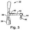
図3は、本発明による好適な締め付け機構22の拡大図を示す。このような好適な締め付け機構22は、ベース部材36、ベース部材36に取り付けたアタッチメントブラケット38、アタッチメントブラケット38に可動に取り付けたレバーアーム40、レバーアーム40に取り付けた締め付けアーム42、及び締め付けアーム42に取り付けた調整可能な接触棒44を備えることが分かる。圧力分配手段46を、車体開口シミュレータ14の凹状空洞16に位置決めしたモジュール式車両窓アセンブリ20の一部に接触する接触ロッド44の遠位端に取り付けてもよい。FIG. 3 shows an enlarged view of a
図4は、モジュール式車両窓アセンブリ20を配置した本発明の装置10を示し、モジュール式車両窓アセンブリ20は、特に車体開口シミュレータ14に対する車両窓アセンブリ20の嵌め付けを評価するための位置に配置され、少なくとも1つの締め付け機構22により保持されている。Figure 4 shows an
シミュレートした車体開口14へのモジュール式窓アセンブリ20の嵌め付けを評価するために前述の装置10を利用する方法も、本発明の範囲内にある。 It is also within the scope of the present invention to utilize the
本発明の方法では、生産準備のできたモジュール式窓アセンブリ20を車体開口シミュレータ14の凹状空洞16に精密に位置決めし、この空洞16の形状は、シミュレート中の車体開口の形状に密接に対応するべきである。車体開口シミュレータ14の寸法間の対応は、±0.2mmであることが好ましい。1つ又は複数の締め付け機構22を動作させて、モジュール式窓アセンブリ20を装置10の凹状空洞16の適所に確実に拘束する。少なくとも1つの光源24を点灯させ少なくとも1つの透光用開口18から投光することにより、車体開口シミュレータ14の凹状空洞の一部又は全部と、位置決めした車両窓アセンブリ20の第1主面26の一部又は全部とを照明するようにする。こうして生成した光は、凹状空洞16の周囲と車両窓アセンブリ20の周囲との間の隙間を通して輝く。これにより検出された隙間は、車両窓アセンブリ20の供給業者の側での、又は車両製造業者の側での、又は両当事者の側での補正措置を必要とする潜在的欠陥を表し得る。いずれにせよ、補正措置を必要とするこのような領域は、こうした嵌め付け及び仕上げの問題が生産ライン上の車両アセンブリに悪影響を及ぼす前に識別されることが好ましい。本発明の方法を、検査治具と称する場合もある品質検査として生産中に利用して、進行中の車両組み立て作業中に生じ得る問題を最小化することができる。In the method of the present invention, a
これまで述べたように、本発明の嵌め付け評価プロセスは主に定性的である。凹状空洞16への車両窓アセンブリ20の嵌め付けの電子画像、例えばデジタル画像を撮影可能であり、且つ上記デジタル画像を解析して凹状空洞16における車両窓20の嵌め付けに関する定量的結果を出すコンピュータに上記デジタル画像を伝送可能であるカメラ又は他のデバイスを組み込むことにより本発明を強化することも、本発明の範囲内にある。特定の好適な実施形態の上記開示及び詳細な説明から、本発明の範囲及び趣旨から逸脱することなく種々の変更、追加、及び他の代替的な実施形態が可能であることが明らかであろう。説明した実施形態は、本発明の原理及びその実際の用途を最もよく説明することにより、当業者が本発明を意図される特定の使用に適するよう種々の実施形態で種々の変更を加えて用いることを可能にするよう、選択及び記載したものである。このような変更及び変形は全て、公正、法的、且つ公平な権利範囲に従って解釈した場合に添付の特許請求の範囲により決定される本発明の範囲内にある。 As described above, the fitting evaluation process of the present invention is mainly qualitative. A computer capable of taking an electronic image, e.g., a digital image, of the fitting of the
Claims (12)
Translated fromJapanese支持ベース部材と、
該ベース部材に取り付けた車体開口シミュレータと、
車両窓アセンブリを前記車体開口シミュレータに固定する1つ又は複数の手段とを備え、
前記車体開口シミュレータは、
車体開口の周囲の正確な形状を有する凹状空洞と、
該凹状空洞の周囲に形成した少なくとも1つの透光用開口と、
該少なくとも1つの透光用開口を通して光を提供するよう配置され、電源に取り付けられた少なくとも1つの光源とを備え、
前記車体開口シミュレータは、前記少なくとも1つの透光用開口を通して前記少なくとも1つの光源から投光させ、前記凹状空洞及び前記凹状空洞に位置決めした車両窓アセンブリのうち前記凹状空洞に面した面を照明させることで、前記凹状空洞の周囲と前記車両窓アセンブリの周囲との間の隙間を露光させるように構成された装置。An apparatus for evaluating the fitting of a modular window assembly to a simulated vehicle body opening,
A support base member;
And the bodyapertures simulator mounted on the basemember,
Thecar both windowassembly and a one or more means for fixing to the vehicle bodyaperturessimulator,
The vehicle body opening simulator is
A concave cavity having an exact shape around the body opening;
At least one light-transmitting opening formed around the concave cavity;
At least one light source arranged to provide light through the at least one light transmissive aperture and attached to a power source;
The vehicle body opening simulator projects light from the at least one light source through the at least one light-transmitting opening, and illuminates a surface facing the concave cavity among the concave cavity and a vehicle window assembly positioned in the concave cavity. it is,an apparatus configuredto clearance Ruis exposed between the surrounding ambient and the vehicle window assembly of the recessed cavity.
支持ベース部材に取り付けられた車体開口シミュレータを設けるステップであって、
該車体開口シミュレータは、
車体開口の周囲の正確な形状を有する凹状空洞と、
該凹状空洞の周囲に形成した少なくとも1つの透光用開口と、
前記少なくとも1つの透光用開口を通して光を提供するように配置され、電源に接続された少なくとも1つの光源とを備えるステップと、
車両窓アセンブリを前記車体開口シミュレータに固定するステップと、
前記凹状空洞及び前記凹状空洞に位置決めした前記車両窓アセンブリのうち前記凹状空洞に面した面を照明するステップと、
前記車体開口シミュレータに対する前記車両窓の嵌め付けを評価するステップとを含む方法。A method of evaluating the fit with the modular window assembly tosimulated car body opening,
Comprising: providinga vehicle bodyapertures simulatorattached to the support basemember,
The vehicle body opening simulator is
A concave cavity having an exact shape around the body opening;
At least one light-transmitting opening formed around the concave cavity;
Providing at least one light source arranged to provide light through said at least one light-transmitting aperture and connected to a power source ;
A step of fixing the vehicle windowassembly to the vehicle bodyapertures simulator,
A step of lightirradiation surface facing the concave cavity of the vehicle windowassemblyhas been positioned in the concave cavity and the concave cavity,
Method comprising the steps of assessing the fit with the vehicle window with respect to the vehicle bodyapertures simulator.
前記車体開口シミュレータの前記凹状空洞に面した第1主面と該凹状空洞に面しない第2主面とを有する前記車両窓アセンブリを、前記凹状空洞に位置決めするステップと、
前記少なくとも1つの透光用開口を通して前記少なくとも1つの光源から投光させ、前記凹状空洞及び前記位置決めした車両窓アセンブリの前記第1主面を照明させることで、前記凹状空洞の周囲と前記車両窓アセンブリの周囲との間の隙間を露光させるステップと、
前記車体開口シミュレータの前記凹状空洞の周囲に対する前記車両窓アセンブリの嵌め付けを、前記凹状空洞及び前記位置決めした車両窓アセンブリの前記第1主面の照明により露光された前記隙間の目視観察により評価するステップと
を含む方法。The method of claim8 , wherein
A step of positioning the vehicle window assembly and a second major surface that does not face the first main surface and the concave cavity facing the concave cavity of the bodyapertures simulator, the concave cavity,
By projecting light from the at least one light source through the at least one light-transmitting opening to illuminate the concave cavity and the first main surface of the positioned vehicle window assembly, the periphery of the concave cavity and the vehicle window Exposing a gap between the periphery of the assembly;
The fit with the vehicle window assembly to the surrounding the concave cavity of the bodyapertures simulator, by visual observation of the concave cavity and the gap exposed by illumination of the first main surface of the positioning the vehicle window assembly And evaluating.
Applications Claiming Priority (3)
| Application Number | Priority Date | Filing Date | Title |
|---|---|---|---|
| US35370110P | 2010-06-11 | 2010-06-11 | |
| US61/353,701 | 2010-06-11 | ||
| PCT/US2011/001008WO2011155977A1 (en) | 2010-06-11 | 2011-06-03 | Apparatus for evaluating fit of a modular assembly into a body opening and method of using same |
Publications (2)
| Publication Number | Publication Date |
|---|---|
| JP2013534620A JP2013534620A (en) | 2013-09-05 |
| JP5819413B2true JP5819413B2 (en) | 2015-11-24 |
Family
ID=44303265
Family Applications (1)
| Application Number | Title | Priority Date | Filing Date |
|---|---|---|---|
| JP2013514153AActiveJP5819413B2 (en) | 2010-06-11 | 2011-06-03 | Apparatus for evaluating the fitting of a module assembly to a vehicle body opening and method of using the apparatus |
Country Status (7)
| Country | Link |
|---|---|
| US (1) | US8723950B2 (en) |
| EP (1) | EP2580107B1 (en) |
| JP (1) | JP5819413B2 (en) |
| KR (1) | KR101874298B1 (en) |
| CN (1) | CN102939236B (en) |
| BR (1) | BR112012031220B1 (en) |
| WO (1) | WO2011155977A1 (en) |
Families Citing this family (2)
| Publication number | Priority date | Publication date | Assignee | Title |
|---|---|---|---|---|
| JP5819413B2 (en)* | 2010-06-11 | 2015-11-24 | ピルキントン グループ リミテッド | Apparatus for evaluating the fitting of a module assembly to a vehicle body opening and method of using the apparatus |
| FR3055956A1 (en)* | 2016-09-09 | 2018-03-16 | Peugeot Citroen Automobiles Sa | METHOD FOR CONTROLLING AT LEAST ONE DIMENSION OF A GLASS FOR OPENING |
Family Cites Families (38)
| Publication number | Priority date | Publication date | Assignee | Title |
|---|---|---|---|---|
| US1912545A (en)* | 1932-10-19 | 1933-06-06 | Girard Model Works Inc | Electrically lighted vehicle toy |
| US2755095A (en)* | 1954-04-14 | 1956-07-17 | Murray Ohio Mfg Co | Airplane simulating juvenile vehicle |
| US3155422A (en)* | 1961-11-06 | 1964-11-03 | Gen Motors Corp | Windshield mounting |
| US4332413A (en)* | 1980-08-15 | 1982-06-01 | Ford Motor Company | Window assembly |
| US4364595A (en)* | 1980-10-06 | 1982-12-21 | Donnelly Mirrors, Inc. | Vehicle window assembly |
| US4561625A (en)* | 1983-09-26 | 1985-12-31 | Libbey-Owens-Ford Company | Mold structure |
| US4700525A (en)* | 1986-04-16 | 1987-10-20 | Donnelly Corporation | Molded panel assembly and fasteners therefor |
| US4909869A (en)* | 1986-12-04 | 1990-03-20 | Mazda Motor Corporation | Method of mounting a window glass on a vehicle body |
| JPH01153232A (en)* | 1987-12-04 | 1989-06-15 | Honda Motor Co Ltd | Assembly inspection tool for vehicle parts |
| US5477268A (en)* | 1991-08-08 | 1995-12-19 | Mazda Motor Corporation | Method of and apparatus for finishing a surface of workpiece |
| US5263759A (en)* | 1991-10-18 | 1993-11-23 | Donnelly Corporation | Vehicular window assembly with wiper support |
| US5551197A (en)* | 1993-09-30 | 1996-09-03 | Donnelly Corporation | Flush-mounted articulated/hinged window assembly |
| US5864996A (en)* | 1994-02-24 | 1999-02-02 | Donnelly Corporation | Gasketed panel |
| US5635281A (en)* | 1994-08-12 | 1997-06-03 | Donnelly Corporation | Glazing using a melt-processible gasket material |
| US5839231A (en)* | 1996-08-02 | 1998-11-24 | Excel Industries, Inc. | Window assembly with light |
| JPH1119830A (en)* | 1997-06-30 | 1999-01-26 | Mazda Motor Corp | Inspecting method of part for automobile and inspecting jig used in this method |
| US6252254B1 (en)* | 1998-02-06 | 2001-06-26 | General Electric Company | Light emitting device with phosphor composition |
| US6203639B1 (en)* | 1998-02-17 | 2001-03-20 | Donnelly Corporation | Vehicle assembly line-side heat activation of a “ready-to-install” window fixing adhesive for attachment of a vehicle window to a vehicle |
| FR2786735B1 (en) | 1998-12-03 | 2001-02-16 | Webasto Systemes Carrosserie | OPENING ROOF ASSEMBLY |
| JP2001004555A (en)* | 1999-06-18 | 2001-01-12 | Hamamatsu Photonics Kk | Container inspecting device |
| US6513949B1 (en)* | 1999-12-02 | 2003-02-04 | Koninklijke Philips Electronics N.V. | LED/phosphor-LED hybrid lighting systems |
| AU2002251807A1 (en)* | 2001-01-23 | 2002-08-19 | Donnelly Corporation | Improved vehicular lighting system for a mirror assembly |
| US7469450B2 (en)* | 2001-11-09 | 2008-12-30 | Dura Global Technologies, Inc. | Articulated window panel with hidden hinge for vehicles |
| US7023358B2 (en)* | 2001-11-27 | 2006-04-04 | Ford Global Technologies Llc | Method and an assembly for determining the existence and the size of a gap |
| DE10224970B4 (en)* | 2002-06-05 | 2007-09-20 | Webasto Ag | Roof module for a vehicle |
| JP4351472B2 (en)* | 2003-06-04 | 2009-10-28 | 本田技研工業株式会社 | Method and apparatus for mounting window glass for automobiles |
| US6964294B2 (en)* | 2003-09-24 | 2005-11-15 | Midwest Research Institute | Passive cooling system for a vehicle |
| US7307675B2 (en) | 2004-12-07 | 2007-12-11 | Planar Systems, Inc. | Display panel with backlighting structure and selectively transmissive window therethrough |
| WO2007047442A1 (en)* | 2005-10-13 | 2007-04-26 | Donnelly Corporation | Acoustical window assembly for vehicle |
| JP2008139041A (en)* | 2006-11-30 | 2008-06-19 | Denso Corp | Manufacturing method of honeycomb structure |
| US20100279255A1 (en)* | 2007-02-16 | 2010-11-04 | Ohio University | Vehicle simulator system |
| DE112008000488T5 (en)* | 2007-02-28 | 2010-02-11 | Shiloh Industries, Inc., Valley City | Metal board with binder trim component and method |
| FR2913945B1 (en)* | 2007-03-20 | 2009-09-25 | Plastic Omnium Cie | ASSEMBLY OF BODY COMPONENT AND OPTICAL GLAZING FOR MOTOR VEHICLE |
| JP4861232B2 (en)* | 2007-04-06 | 2012-01-25 | 本田技研工業株式会社 | Lid member mounting method and apparatus |
| US8091948B2 (en)* | 2008-04-28 | 2012-01-10 | Atwood Mobile Products, Llc | Flush-closing window for motor vehicles and method, guide track system and pin assembly therefor |
| CN201380890Y (en)* | 2008-12-25 | 2010-01-13 | 上海汽车集团股份有限公司 | Glass positioning block structure |
| JP5819413B2 (en)* | 2010-06-11 | 2015-11-24 | ピルキントン グループ リミテッド | Apparatus for evaluating the fitting of a module assembly to a vehicle body opening and method of using the apparatus |
| JP2013009041A (en)* | 2011-06-22 | 2013-01-10 | Denso Corp | Vehicle photographing display control system |
- 2011
- 2011-06-03JPJP2013514153Apatent/JP5819413B2/enactiveActive
- 2011-06-03CNCN201180028714.8Apatent/CN102939236B/enactiveActive
- 2011-06-03EPEP11726241.0Apatent/EP2580107B1/enactiveActive
- 2011-06-03KRKR1020127032220Apatent/KR101874298B1/enactiveActive
- 2011-06-03WOPCT/US2011/001008patent/WO2011155977A1/enactiveApplication Filing
- 2011-06-03BRBR112012031220-0Apatent/BR112012031220B1/enactiveIP Right Grant
- 2011-06-03USUS13/152,358patent/US8723950B2/enactiveActive
Also Published As
| Publication number | Publication date |
|---|---|
| US8723950B2 (en) | 2014-05-13 |
| EP2580107A1 (en) | 2013-04-17 |
| US20110304727A1 (en) | 2011-12-15 |
| CN102939236B (en) | 2017-03-08 |
| BR112012031220B1 (en) | 2020-12-29 |
| WO2011155977A1 (en) | 2011-12-15 |
| KR101874298B1 (en) | 2018-07-06 |
| JP2013534620A (en) | 2013-09-05 |
| KR20130082087A (en) | 2013-07-18 |
| BR112012031220A2 (en) | 2016-10-25 |
| EP2580107B1 (en) | 2016-08-24 |
| CN102939236A (en) | 2013-02-20 |
Similar Documents
| Publication | Publication Date | Title |
|---|---|---|
| KR101393755B1 (en) | Electrodes for spot welding | |
| CN104534950B (en) | A kind of micrometer verification system | |
| US20080316476A1 (en) | System and Device for the Optical Inspection of Glass Panels | |
| CA2675028C (en) | Method and apparatus for the examination of an object | |
| CN204154656U (en) | A CCD visual detection device | |
| CN212845071U (en) | Keycap inspection device and keycap inspection equipment | |
| JP5819413B2 (en) | Apparatus for evaluating the fitting of a module assembly to a vehicle body opening and method of using the apparatus | |
| CN202082821U (en) | Car headlight dimmer | |
| CN206563550U (en) | Device for the high-precision dimensional measurement of finding | |
| CN117190862A (en) | A method for detecting the position of an optical fiber clamped by an optical fiber clamp | |
| KR101884154B1 (en) | Apparatus for inspecting instrument panel for vehicle | |
| CN210953838U (en) | A multi-functional physical evidence tester related to legal science | |
| JP4354941B2 (en) | Vision and brightness detection system for backlight unit | |
| CN213209886U (en) | Optical detection device | |
| JP4608399B2 (en) | Inspection device for illumination optical element | |
| CN221650820U (en) | A watch visual testing component | |
| CN223449809U (en) | Table type biological material detecting machine | |
| CN223166578U (en) | A combined detection system | |
| CN217424726U (en) | Ball pin pull rod swing torque tester | |
| JP6336167B1 (en) | Guide light inspection instrument and guide light inspection method | |
| KR0155096B1 (en) | Concentricity and parallelism inspection device of a sled part of optical pick up base | |
| KR20180036527A (en) | A tape inspector | |
| JP2011012959A (en) | Guide light inspection implement and method of inspecting guide light | |
| JP2017067449A (en) | Defective portion clear indication method, defective portion clear indication device, and defective portion clear indication program | |
| JP2724249B2 (en) | Adjustment jig for lens performance inspection device |
Legal Events
| Date | Code | Title | Description |
|---|---|---|---|
| A621 | Written request for application examination | Free format text:JAPANESE INTERMEDIATE CODE: A621 Effective date:20140603 | |
| A977 | Report on retrieval | Free format text:JAPANESE INTERMEDIATE CODE: A971007 Effective date:20150225 | |
| A131 | Notification of reasons for refusal | Free format text:JAPANESE INTERMEDIATE CODE: A131 Effective date:20150303 | |
| A601 | Written request for extension of time | Free format text:JAPANESE INTERMEDIATE CODE: A601 Effective date:20150528 | |
| A601 | Written request for extension of time | Free format text:JAPANESE INTERMEDIATE CODE: A601 Effective date:20150803 | |
| A521 | Request for written amendment filed | Free format text:JAPANESE INTERMEDIATE CODE: A523 Effective date:20150820 | |
| TRDD | Decision of grant or rejection written | ||
| A01 | Written decision to grant a patent or to grant a registration (utility model) | Free format text:JAPANESE INTERMEDIATE CODE: A01 Effective date:20150915 | |
| A61 | First payment of annual fees (during grant procedure) | Free format text:JAPANESE INTERMEDIATE CODE: A61 Effective date:20150930 | |
| R150 | Certificate of patent or registration of utility model | Ref document number:5819413 Country of ref document:JP Free format text:JAPANESE INTERMEDIATE CODE: R150 | |
| R250 | Receipt of annual fees | Free format text:JAPANESE INTERMEDIATE CODE: R250 | |
| R250 | Receipt of annual fees | Free format text:JAPANESE INTERMEDIATE CODE: R250 | |
| R250 | Receipt of annual fees | Free format text:JAPANESE INTERMEDIATE CODE: R250 | |
| R250 | Receipt of annual fees | Free format text:JAPANESE INTERMEDIATE CODE: R250 | |
| R250 | Receipt of annual fees | Free format text:JAPANESE INTERMEDIATE CODE: R250 | |
| R250 | Receipt of annual fees | Free format text:JAPANESE INTERMEDIATE CODE: R250 | |
| R250 | Receipt of annual fees | Free format text:JAPANESE INTERMEDIATE CODE: R250 |