JP5819295B2 - Cleaning syringe assembly - Google Patents
Cleaning syringe assemblyDownload PDFInfo
- Publication number
- JP5819295B2 JP5819295B2JP2012519770AJP2012519770AJP5819295B2JP 5819295 B2JP5819295 B2JP 5819295B2JP 2012519770 AJP2012519770 AJP 2012519770AJP 2012519770 AJP2012519770 AJP 2012519770AJP 5819295 B2JP5819295 B2JP 5819295B2
- Authority
- JP
- Japan
- Prior art keywords
- plunger rod
- barrel
- syringe assembly
- cleaning
- distal
- Prior art date
- Legal status (The legal status is an assumption and is not a legal conclusion. Google has not performed a legal analysis and makes no representation as to the accuracy of the status listed.)
- Active
Links
Images


Classifications
- A—HUMAN NECESSITIES
- A61—MEDICAL OR VETERINARY SCIENCE; HYGIENE
- A61M—DEVICES FOR INTRODUCING MEDIA INTO, OR ONTO, THE BODY; DEVICES FOR TRANSDUCING BODY MEDIA OR FOR TAKING MEDIA FROM THE BODY; DEVICES FOR PRODUCING OR ENDING SLEEP OR STUPOR
- A61M5/00—Devices for bringing media into the body in a subcutaneous, intra-vascular or intramuscular way; Accessories therefor, e.g. filling or cleaning devices, arm-rests
- A61M5/178—Syringes
- A61M5/31—Details
- A61M5/315—Pistons; Piston-rods; Guiding, blocking or restricting the movement of the rod or piston; Appliances on the rod for facilitating dosing ; Dosing mechanisms
- A61M5/31501—Means for blocking or restricting the movement of the rod or piston
- A61M5/31505—Integral with the syringe barrel, i.e. connected to the barrel so as to make up a single complete piece or unit
- A—HUMAN NECESSITIES
- A61—MEDICAL OR VETERINARY SCIENCE; HYGIENE
- A61M—DEVICES FOR INTRODUCING MEDIA INTO, OR ONTO, THE BODY; DEVICES FOR TRANSDUCING BODY MEDIA OR FOR TAKING MEDIA FROM THE BODY; DEVICES FOR PRODUCING OR ENDING SLEEP OR STUPOR
- A61M5/00—Devices for bringing media into the body in a subcutaneous, intra-vascular or intramuscular way; Accessories therefor, e.g. filling or cleaning devices, arm-rests
- A61M5/178—Syringes
- A61M5/31—Details
- A61M5/3129—Syringe barrels
- A—HUMAN NECESSITIES
- A61—MEDICAL OR VETERINARY SCIENCE; HYGIENE
- A61M—DEVICES FOR INTRODUCING MEDIA INTO, OR ONTO, THE BODY; DEVICES FOR TRANSDUCING BODY MEDIA OR FOR TAKING MEDIA FROM THE BODY; DEVICES FOR PRODUCING OR ENDING SLEEP OR STUPOR
- A61M5/00—Devices for bringing media into the body in a subcutaneous, intra-vascular or intramuscular way; Accessories therefor, e.g. filling or cleaning devices, arm-rests
- A61M5/178—Syringes
- A61M5/31—Details
- A61M5/315—Pistons; Piston-rods; Guiding, blocking or restricting the movement of the rod or piston; Appliances on the rod for facilitating dosing ; Dosing mechanisms
- A61M5/31501—Means for blocking or restricting the movement of the rod or piston
- A—HUMAN NECESSITIES
- A61—MEDICAL OR VETERINARY SCIENCE; HYGIENE
- A61M—DEVICES FOR INTRODUCING MEDIA INTO, OR ONTO, THE BODY; DEVICES FOR TRANSDUCING BODY MEDIA OR FOR TAKING MEDIA FROM THE BODY; DEVICES FOR PRODUCING OR ENDING SLEEP OR STUPOR
- A61M5/00—Devices for bringing media into the body in a subcutaneous, intra-vascular or intramuscular way; Accessories therefor, e.g. filling or cleaning devices, arm-rests
- A61M5/178—Syringes
- A61M5/31—Details
- A61M5/315—Pistons; Piston-rods; Guiding, blocking or restricting the movement of the rod or piston; Appliances on the rod for facilitating dosing ; Dosing mechanisms
- A61M5/31511—Piston or piston-rod constructions, e.g. connection of piston with piston-rod
- A—HUMAN NECESSITIES
- A61—MEDICAL OR VETERINARY SCIENCE; HYGIENE
- A61M—DEVICES FOR INTRODUCING MEDIA INTO, OR ONTO, THE BODY; DEVICES FOR TRANSDUCING BODY MEDIA OR FOR TAKING MEDIA FROM THE BODY; DEVICES FOR PRODUCING OR ENDING SLEEP OR STUPOR
- A61M5/00—Devices for bringing media into the body in a subcutaneous, intra-vascular or intramuscular way; Accessories therefor, e.g. filling or cleaning devices, arm-rests
- A61M5/178—Syringes
- A61M5/31—Details
- A61M5/315—Pistons; Piston-rods; Guiding, blocking or restricting the movement of the rod or piston; Appliances on the rod for facilitating dosing ; Dosing mechanisms
- A61M5/31565—Administration mechanisms, i.e. constructional features, modes of administering a dose
- A61M5/3159—Dose expelling manners
- A61M5/31593—Multi-dose, i.e. individually set dose repeatedly administered from the same medicament reservoir
- A61M5/31595—Pre-defined multi-dose administration by repeated overcoming of means blocking the free advancing movement of piston rod, e.g. by tearing or de-blocking
- A—HUMAN NECESSITIES
- A61—MEDICAL OR VETERINARY SCIENCE; HYGIENE
- A61M—DEVICES FOR INTRODUCING MEDIA INTO, OR ONTO, THE BODY; DEVICES FOR TRANSDUCING BODY MEDIA OR FOR TAKING MEDIA FROM THE BODY; DEVICES FOR PRODUCING OR ENDING SLEEP OR STUPOR
- A61M5/00—Devices for bringing media into the body in a subcutaneous, intra-vascular or intramuscular way; Accessories therefor, e.g. filling or cleaning devices, arm-rests
- A61M5/178—Syringes
- A61M5/31—Details
- A61M2005/3143—Damping means for syringe components executing relative movements, e.g. retarders or attenuators slowing down or timing syringe mechanisms
- A—HUMAN NECESSITIES
- A61—MEDICAL OR VETERINARY SCIENCE; HYGIENE
- A61M—DEVICES FOR INTRODUCING MEDIA INTO, OR ONTO, THE BODY; DEVICES FOR TRANSDUCING BODY MEDIA OR FOR TAKING MEDIA FROM THE BODY; DEVICES FOR PRODUCING OR ENDING SLEEP OR STUPOR
- A61M5/00—Devices for bringing media into the body in a subcutaneous, intra-vascular or intramuscular way; Accessories therefor, e.g. filling or cleaning devices, arm-rests
- A61M5/178—Syringes
- A61M5/31—Details
- A61M5/315—Pistons; Piston-rods; Guiding, blocking or restricting the movement of the rod or piston; Appliances on the rod for facilitating dosing ; Dosing mechanisms
- A61M5/31501—Means for blocking or restricting the movement of the rod or piston
- A61M2005/31508—Means for blocking or restricting the movement of the rod or piston provided on the piston-rod
- A—HUMAN NECESSITIES
- A61—MEDICAL OR VETERINARY SCIENCE; HYGIENE
- A61M—DEVICES FOR INTRODUCING MEDIA INTO, OR ONTO, THE BODY; DEVICES FOR TRANSDUCING BODY MEDIA OR FOR TAKING MEDIA FROM THE BODY; DEVICES FOR PRODUCING OR ENDING SLEEP OR STUPOR
- A61M5/00—Devices for bringing media into the body in a subcutaneous, intra-vascular or intramuscular way; Accessories therefor, e.g. filling or cleaning devices, arm-rests
- A61M5/178—Syringes
- A61M5/31—Details
- A61M5/315—Pistons; Piston-rods; Guiding, blocking or restricting the movement of the rod or piston; Appliances on the rod for facilitating dosing ; Dosing mechanisms
- A61M5/31501—Means for blocking or restricting the movement of the rod or piston
- A61M2005/3151—Means for blocking or restricting the movement of the rod or piston by friction
- A—HUMAN NECESSITIES
- A61—MEDICAL OR VETERINARY SCIENCE; HYGIENE
- A61M—DEVICES FOR INTRODUCING MEDIA INTO, OR ONTO, THE BODY; DEVICES FOR TRANSDUCING BODY MEDIA OR FOR TAKING MEDIA FROM THE BODY; DEVICES FOR PRODUCING OR ENDING SLEEP OR STUPOR
- A61M25/00—Catheters; Hollow probes
- A61M2025/0019—Cleaning catheters or the like, e.g. for reuse of the device, for avoiding replacement
- A—HUMAN NECESSITIES
- A61—MEDICAL OR VETERINARY SCIENCE; HYGIENE
- A61M—DEVICES FOR INTRODUCING MEDIA INTO, OR ONTO, THE BODY; DEVICES FOR TRANSDUCING BODY MEDIA OR FOR TAKING MEDIA FROM THE BODY; DEVICES FOR PRODUCING OR ENDING SLEEP OR STUPOR
- A61M2206/00—Characteristics of a physical parameter; associated device therefor
- A61M2206/10—Flow characteristics
Landscapes
- Health & Medical Sciences (AREA)
- Vascular Medicine (AREA)
- Engineering & Computer Science (AREA)
- Anesthesiology (AREA)
- Biomedical Technology (AREA)
- Heart & Thoracic Surgery (AREA)
- Hematology (AREA)
- Life Sciences & Earth Sciences (AREA)
- Animal Behavior & Ethology (AREA)
- General Health & Medical Sciences (AREA)
- Public Health (AREA)
- Veterinary Medicine (AREA)
- Infusion, Injection, And Reservoir Apparatuses (AREA)
- Media Introduction/Drainage Providing Device (AREA)
Description
Translated fromJapanese本発明は、シリンジ組立体、特に、血管アクセス器具(VAD)の洗浄方法における使用のためのシリンジ組立体に関する。 The present invention relates to a syringe assembly, and in particular to a syringe assembly for use in a vascular access device (VAD) cleaning method.
VADは、通常、治療用器具に使用され、IVカテーテルを含む。二つの一般的なVADの分類、末梢カテーテルおよび中心静脈カテーテル、が存在する。適正に維持されないと、VADは閉塞されることになり得る。VADが適正に使用され、閉塞されてしまわないことを確実にするために、業務標準が発展させられてきた。これらの標準は、洗浄方法またはカテーテルを洗浄することとして通常言及される、清浄方法を含む。 VAD is typically used for therapeutic instruments and includes IV catheters. There are two general classifications of VAD, peripheral catheters and central venous catheters. If not properly maintained, the VAD can become occluded. Business standards have been developed to ensure that VAD is properly used and not blocked. These standards include cleaning methods, commonly referred to as cleaning methods or cleaning catheters.
VAD業務標準は、普通、カテーテルの配置後、流体注入前、ならびに、薬剤投与、血液サンプリング、輸液および経静脈栄養の前後に、清浄方法が実施されることを推奨していた。これらの洗浄方法の目的は、カテーテルの開通性を確認し、薬剤の不適合性を回避し、完全な薬剤投与管理を確実にし、血栓形成を防止し、血流感染症の危険を最小化することである。洗浄方法は、異なるタイプおよび量の洗浄液を要求する。最も普通に用いられる洗浄液は、生理食塩水および/またはヘパリンロック洗浄液である。洗浄液のタイプおよび量は、特定の種類のカテーテルに依存して変化する。5〜10mlの洗浄液量が最も普通であるが、1〜20mlの範囲であり得る。 VAD practice standards usually recommended that cleaning methods be performed after catheter placement, before fluid infusion, and before and after drug administration, blood sampling, infusion, and parenteral nutrition. The purpose of these cleaning methods is to confirm catheter patency, avoid drug incompatibility, ensure complete drug administration control, prevent thrombus formation, and minimize the risk of bloodstream infections It is. Cleaning methods require different types and amounts of cleaning liquid. The most commonly used cleaning solution is saline and / or heparin lock cleaning solution. The type and amount of irrigation fluid will vary depending on the particular type of catheter. A wash solution volume of 5-10 ml is most common, but can range from 1-20 ml.
洗浄方法のために、I.V.ラインは、VAD、クランプ付チューブセットを含み、および、開口部または弁で終わり得るシステムに言及する。最も典型的なタイプの開口部は、穿刺可能セプタムまたは予めスリットが入ったセプタムによって被覆されており、当該技術分野においては知られており、「必要に応じて」を意味する、ラテン語の「pro re nata」から、「PRN」としてしばしば言及される。セプタムは、好ましくは、流体を注入するため、または、カテーテルから流体を引き込むために、鋭い針カニューレの挿入を可能にする、ゴムまたは他のエラストマー材料で製造される。針カニューレの引き抜きで、セプタムは、自身をシールする。予めスリットの入ったセプタムを有する開口部は、ブラントカニューレまたはシリンジバレルの円錐台形状の先端と一緒に使用される。シリンジの先端またはブラントカニューレ(通常、シリンジに取り付けられる。)は、流体連通を確立するために、予めスリットの入ったセプタムを通して徐々に押入される。 For the cleaning method, I.D. V. The line refers to a system that includes a VAD, a set of clamped tubes, and can be terminated with an opening or valve. The most typical type of opening is covered by a pierceable septum or a pre-slit septum and is known in the art and refers to the Latin “pro” meaning “as needed” From “renata”, it is often referred to as “PRN”. The septum is preferably made of rubber or other elastomeric material that allows the insertion of a sharp needle cannula for injecting fluid or drawing fluid from the catheter. Upon withdrawal of the needle cannula, the septum seals itself. An opening with a pre-slit septum is used with a frustoconical tip of a blunt cannula or syringe barrel. The syringe tip or blunt cannula (usually attached to the syringe) is gradually pushed through a pre-slit septum to establish fluid communication.
鋭い先端を有する針を必要としない、I.V.弁、他のタイプの末端I.V.アクセス器具は、シリンジの円錐台形状の先端によって動かされ、シリンジ内部とカテーテルとの流体連通を可能にする。これらの弁は、弁の貯蔵区画からカテーテルへ流体を供給するための態様を含み得、当該技術分野において、容積型弁として言及される。そのような弁は、特許文献1に記載されている。 Does not require a needle with a sharp tip; V. Valves, other types of end I.V. V. The access device is moved by the frustoconical tip of the syringe and allows fluid communication between the syringe interior and the catheter. These valves may include embodiments for supplying fluid from the valve storage compartment to the catheter, referred to in the art as positive displacement valves. Such a valve is described in US Pat.
洗浄方法は、閉塞または他の望ましくない作用を引き起こす、カテーテル内の破片または残滓を除去するための「プッシュ−パルス」(また、「スタート−ストップ」または「プッシュ−ポーズ」と呼ばれる。)技術の使用によって強化される。破片または残滓の除去は、パージと呼ばれ、カテーテルまたは他のVAD器具内の、血液の沈積物、血液残滓およびIV薬剤の蓄積を防止する。そのような蓄積は、カテーテルシステム内における流路の部分的または完全な閉塞を引き起こし、影響を受けたカテーテルのパージのために高価な、潜在的に危険な方法を要求するか、全体的なカテーテルの交換を要求する。しばしば、そのような閉塞は、患者治療を危険にさらし得る治療の中断をもたらす。カテーテル内の残滓の蓄積は、また、微生物の繁殖媒体を提供することによって、伝染病の危険を増大させ得る。この理由から、プッシュ−パルスは、伝統的に、医療従事者に教えられている。 The cleaning method is a “push-pulse” (also called “start-stop” or “push-pause”) technique for removing debris or debris in the catheter that causes occlusion or other undesirable effects. Enhance by use. The removal of debris or debris is called purging and prevents the accumulation of blood deposits, blood debris and IV drugs in a catheter or other VAD device. Such accumulation causes partial or complete blockage of the flow path within the catheter system, requiring expensive, potentially dangerous methods for purging the affected catheter, or the overall catheter Request replacement. Often, such occlusions result in treatment interruptions that can endanger patient treatment. The accumulation of debris in the catheter can also increase the risk of infectious diseases by providing a microbial propagation medium. For this reason, push-pulse is traditionally taught to healthcare professionals.
当業者に理解されるように、プッシュ−パルス洗浄技術は、排出中、プランジャーロッドの遠位端がバレル壁に向って移動する際に、不均一な圧力または力が遠位方向にプランジャーロッドに適用されると、シリンジバレル内に乱流を導入または生成する。この開示において、機器の遠位端は患者に最も近い端であり、機器の近位端は患者から遠い端であって、治療者に最も近い端であることが理解される。そのような技術がカテーテルと共に使用されるとき、カテーテル内に乱流が生成される。乱流または脈流は、カテーテルに付着したいかなる破片または残滓をも移動させるスワール作用をもたらす。乱流または脈流は、流体流れおよび圧力に鋭いパルスを自動的に生起するために、プランジャーロッドが前方に押圧される際、シリンジバレルと相互作用するプランジャーロッドを含むシリンジによって、かなり制御された方法で提供され得る。プッシュ−パルスおよび制御された脈動に対して、従来の、または、「スムース」(また、「ストレート」、「ラミナー」と呼ばれる。)な洗浄技術は、遠位方向に、プランジャーロッドに対して実質的に一定の圧力または力を適用することを要求する。従来の、または、スムースな洗浄技術は、また、遠位方向に、プランジャーロッドに対し、実質的に直線状に増大または減少する圧力または力の適用を含み得る。しかしながら、乱流または脈流を引き起こす力の差を提供する態様の使用は、患者への医薬の緩やかで制御された供給を要求する注入ポンプまたは他の供給システムとは一般的には適合しない。例えば、ある注入ポンプは、高圧警報器を有しており、プッシュ−パルス洗浄技術によって生成される力および/または圧力は、高圧警報器を始動させ得る。 As will be appreciated by those skilled in the art, the push-pulse cleaning technique may cause uneven pressure or force to move the plunger distally as the distal end of the plunger rod moves toward the barrel wall during ejection. When applied to the rod, it introduces or creates turbulence in the syringe barrel. In this disclosure, it is understood that the distal end of the instrument is the end closest to the patient and the proximal end of the instrument is the end far from the patient and the end closest to the therapist. When such a technique is used with a catheter, turbulence is created in the catheter. Turbulence or pulsation results in a swirling action that moves any debris or debris attached to the catheter. Turbulence or pulsation is controlled significantly by a syringe that includes a plunger rod that interacts with the syringe barrel when the plunger rod is pushed forward to automatically generate sharp pulses in the fluid flow and pressure. Can be provided in a customized manner. For push-pulses and controlled pulsations, conventional or “smooth” (also referred to as “straight”, “laminar”) cleaning techniques are applied distally to the plunger rod. Requires applying a substantially constant pressure or force. Conventional or smooth cleaning techniques may also include the application of pressure or force that increases or decreases substantially linearly with respect to the plunger rod in the distal direction. However, the use of embodiments that provide a differential force that causes turbulence or pulsation is generally not compatible with infusion pumps or other delivery systems that require a slow and controlled delivery of medication to the patient. For example, some infusion pumps have a high pressure alarm, and the force and / or pressure generated by the push-pulse cleaning technique can trigger the high pressure alarm.
手動のIV治療および注入ポンプを用いる治療の双方に使用され得る洗浄シリンジ組立体の必要性が存在する。 There is a need for a wash syringe assembly that can be used for both manual IV therapy and therapy with an infusion pump.
本発明は、洗浄用途における使用のためのシリンジ組立体に向けられる。本発明の第一態様によるシリンジ組立体は、バレルに対するプランジャーロッドの連続的でスムースな移動と、シリンジバレル内の遠位方向へのプランジャーロッドの脈動を可能にすることを有する、プランジャーロッドおよびシリンジバレルを含む。ここに説明されるシリンジ組立体は、また、バレル内でのプランジャーロッドの脈動または連続的でスムースな移動を選択する可能性を、使用者に提供する。脈動を提供する態様は、使用者が、洗浄シリンジに接続されたカテーテルまたは他の医療機器内の洗浄液の流れに乱流を与えるプッシュ−パルス洗浄技術の作用を達成することを実質的に可能にする。連続的でスムースな移動を提供するための態様は、使用者が、カテーテルまたは他の医療機器内の洗浄液の流れにおける乱流を盛大に変化または増大させることがない、スムースな洗浄技術を利用することを可能にする。脈動および連続的でスムースな移動の範囲は、以下により十分に説明される。 The present invention is directed to a syringe assembly for use in cleaning applications. The syringe assembly according to the first aspect of the present invention comprises a plunger that allows continuous and smooth movement of the plunger rod relative to the barrel and pulsation of the plunger rod distally within the syringe barrel. Includes rod and syringe barrel. The syringe assembly described herein also provides the user with the possibility to choose between pulsating or continuous and smooth movement of the plunger rod within the barrel. Aspects that provide pulsation substantially allow the user to achieve the effect of a push-pulse cleaning technique that turbulently flows the cleaning fluid in a catheter or other medical device connected to the cleaning syringe. To do. Embodiments for providing continuous and smooth movement utilize a smooth cleaning technique that does not allow the user to significantly change or increase the turbulence in the flow of cleaning fluid within a catheter or other medical device. Make it possible. The range of pulsation and continuous smooth movement is more fully described below.
一つ以上の具体例において、プランジャーロッドの脈動または連続的でスムースな移動は、相補的であって、バレルの内容物を排出するときにプッシュ−パルス技術の作用を実質的に達成し、一方で、また、従来の、または、スムースな洗浄技術を代わって提供できるように形成されるか配列され得る、プランジャーロッドおよび/またはシリンジバレルに配置された一つ以上のパルス要素によって提供される。洗浄技術の選択は、特定の適用または患者の特定の要求に対し、使用者によって調整される。プランジャーロッドおよびシリンジバレル組立体が、流体の流れおよび/または圧力にパルスまたは急速な意図した変化を生成するための脈動、または、流体の流れおよび/または圧力が、圧力にわずかの変動またはスパイクを伴って、実質的に一定である、従来の、または、スムースな洗浄をもたらす、連続的でスムースな移動のために設定されているかの可視的な表示を提供する目印がプランジャーロッドおよび/またはシリンジバレルに設けられる。 In one or more embodiments, the pulsation or continuous smooth movement of the plunger rod is complementary and substantially achieves the action of the push-pulse technique when ejecting the contents of the barrel; On the other hand, also provided by one or more pulse elements located on the plunger rod and / or syringe barrel, which may be formed or arranged to provide alternatives to conventional or smooth cleaning techniques. The The choice of cleaning technique is tailored by the user for a particular application or patient specific requirement. The pulsation for the plunger rod and syringe barrel assembly to produce a pulse or rapid intended change in fluid flow and / or pressure, or the fluid flow and / or pressure may vary slightly or spike in pressure With a plunger rod and / or a marker that provides a visual indication of whether it is set for continuous, smooth movement, resulting in a conventional or smooth cleaning that is substantially constant Or it is provided in a syringe barrel.
ここに用いられるように、用語「脈動」は、プランジャーロッドに適用される圧力または力の変動によって引き起こされるプランジャーロッドの動きを含むものとする。ここに説明される具体例において、プランジャーロッドに適用される圧力または力の変動は、プランジャーロッドがバレル内を遠位方向に進行することを可能にするために乗り越えられねばならないプランジャーロッドおよび/またはバレルに配置された一つ以上のパルス要素間の相互作用によって提供される物理的障壁によってもたらされる。プランジャーロッドに配置された一つ以上のパルス要素および/またはバレルに配置された一つ以上のパルス要素の相互作用によって引き起こされるプランジャーロッドの移動、および、プランジャーロッドへの力の適用で、バレルの一つ以上のパルス要素を通過するプランジャーロッドの一つ以上のパルス要素の移動における遅延は、脈動、および、乱れた、または、脈動する洗浄流体圧力をもたらすのに必要な力を産出する。これらは、洗浄液がカテーテルまたは他の医療機器に排出されるとき、洗浄液に乱流を与える圧力または力を変化させる。 As used herein, the term “pulsation” is intended to include plunger rod movement caused by fluctuations in pressure or force applied to the plunger rod. In the embodiment described herein, the variation in pressure or force applied to the plunger rod must be overcome to allow the plunger rod to travel distally through the barrel. And / or provided by a physical barrier provided by interaction between one or more pulse elements arranged in the barrel. Movement of the plunger rod caused by the interaction of one or more pulse elements arranged on the plunger rod and / or one or more pulse elements arranged on the barrel, and application of force to the plunger rod The delay in the movement of one or more pulse elements of the plunger rod through the one or more pulse elements of the barrel may cause pulsation and the force required to produce a turbulent or pulsating cleaning fluid pressure. To produce. These change the pressure or force that imparts turbulence to the cleaning fluid as it is drained into the catheter or other medical device.
圧力または力の変動は、増大または減少し得、そのような変化は、周期的または非周期的に生じ得る。圧力または力の変動は、さらに、予め決められた量で増大または減少するように変更され得る。ここに説明されるように、圧力または力の変化は、プランジャーロッドへの遠位方向のみにおける力の適用による、プランジャーロッドがバレル内を遠位または近位に滑動するときのプランジャーロッドとバレル間の機械的な相互作用における変化によって生起される。ここに用いられるように、用語「相互作用」は、成句「機械的な相互干渉または力」と互換的に使用されるものとし、摩擦、摩擦的な相互干渉または摩擦力を含む。プランジャーロッドに適用される圧力または力の変動は、流体圧力に急激な変化をもたらし、約2秒未満または約1秒未満の期間を有する圧力スパイクをもたらし得る。各々のスパイク期間中、圧力は、約0.70kg/cm2未満または約0.35kg/cm2未満の低圧力値から変動し、急に、1.76kg/cm2に至るまでの高い値に増大し、そして、速やかに、約1.41kg/cm2、1.27kg/cm2、1.12kg/cm2、0.98kg/cm2、0.84kg/cm2、0.70kg/cm2、または、約0.35kg/cm2未満の低圧力値に減少する。ある具体例によれば、複数の圧力スパイクは、実質的に同じであり、スパイクの高い値間の変動は、約0.70kg/cm2未満または約0.35kg/cm2未満であることを意味する。高い圧力値は、プランジャーロッドおよび/またはシリンジバレルに配置された態様の形を変更することにより、特定の適用に調整され得る。Pressure or force fluctuations can increase or decrease, and such changes can occur periodically or aperiodically. The pressure or force variation can be further modified to increase or decrease by a predetermined amount. As described herein, the change in pressure or force is due to the plunger rod as the plunger rod slides distally or proximally within the barrel by application of force in the distal direction only to the plunger rod. Caused by changes in the mechanical interaction between and the barrel. As used herein, the term “interaction” shall be used interchangeably with the phrase “mechanical interaction or force” and includes friction, frictional interaction or friction force. Variations in the pressure or force applied to the plunger rod can cause a sudden change in fluid pressure, resulting in a pressure spike having a duration of less than about 2 seconds or less than about 1 second. In each spike duration, pressure will vary from about 0.70 kg / cm2 or less than the low pressure value of less than about 0.35 kg / cm2, suddenly, the high value of up to 1.76 kg / cm2 Increased and rapidly about 1.41 kg / cm2 , 1.27 kg / cm2 , 1.12 kg / cm2 , 0.98 kg / cm2 , 0.84 kg / cm2 , 0.70 kg / cm2 Or a low pressure value of less than about 0.35 kg / cm2 . According to certain embodiments, a plurality of pressure spikes are substantially the same, the variation between high spike value is less than about less than 0.70 kg / cm2, or about 0.35 kg / cm2 means. High pressure values can be tailored to specific applications by changing the shape of the embodiment located on the plunger rod and / or syringe barrel.
ここに用いられるように、成句「連続的でスムースな移動」は、プランジャーロッドがバレル内の最も近位の位置から、バレル内の最も遠位の位置、すなわち、ストッパーの遠位面がバレルの遠位壁に接触するときの位置まで移動する際に、プランジャーロッドに適用される実質的に一定の圧力または力により引き起こされる移動を含むものとされる。連続的でスムースな移動は、また、実質的に線状である、圧力が約2秒未満で増大し減少する急速な圧力のスパイクから区別される、圧力または力の増大によって引き起こされる移動を含み得る。プランジャーロッドに適用される、一定の、または、線状に増大する圧力または力は、プランジャーロッドがバレル内を移動するとき、プランジャーロッドとの間の機械的干渉における変化の不存在によって引き起こされる。機械的干渉の変化または変化の不存在は、プランジャーロッドがバレル内を遠位および/または近位に滑動するときに生じ得ることが理解されるであろう。プランジャーロッドへのそのような力または圧力の適用は、ストレート洗浄、スムース洗浄またはラミナー洗浄として知られている。 As used herein, the phrase “continuous and smooth movement” means that the plunger rod is moved from the most proximal position in the barrel to the most distal position in the barrel, ie, the distal surface of the stopper is the barrel. It is intended to include movement caused by a substantially constant pressure or force applied to the plunger rod in moving to the position when contacting the distal wall of the plunger rod. Continuous and smooth movement also includes movement caused by an increase in pressure or force, which is substantially linear, as distinguished from rapid pressure spikes where pressure increases and decreases in less than about 2 seconds. obtain. The constant or linearly increasing pressure or force applied to the plunger rod is due to the absence of changes in mechanical interference with the plunger rod as it moves through the barrel. Is caused. It will be appreciated that the change in mechanical interference or the absence of change may occur when the plunger rod slides distally and / or proximally within the barrel. The application of such force or pressure to the plunger rod is known as straight cleaning, smooth cleaning or laminar cleaning.
連続的でスムースな移動および脈動は、プランジャーロッドのストッパーがバレルの近位端に配置され、バレルの実質的な全長に沿って遠位方向に、プランジャーロッドがシリンジの遠位壁に至るまで移動させられるときに生ずる。他の用語で説明すると、連続的でスムースな移動および脈動は、また、バレルの全内容物を排出するために、使用者が、プランジャーロッドに遠位方向の圧力または力を適用するときに生じる。換言すると、連続的でスムースな移動および脈動は、プランジャーロッドがバレル内をバレル内の最も近位点からバレル内の最も遠位点まで、遠位方向に移動するとき、プランジャーロッドの単一ストロークで生じる。 Continuous and smooth movement and pulsation is achieved with a plunger rod stopper located at the proximal end of the barrel, distally along the substantial length of the barrel, and the plunger rod leading to the distal wall of the syringe. Occurs when moved to. In other terms, continuous smooth movement and pulsation can also occur when a user applies distal pressure or force to the plunger rod to expel the entire contents of the barrel. Arise. In other words, continuous and smooth movement and pulsation is the simple movement of the plunger rod as it moves distally in the barrel from the most proximal point in the barrel to the most distal point in the barrel. It occurs in one stroke.
手動のプッシュ−パルス洗浄技術は、カテーテルおよび他の類似の医療機器からパージされるか除去されず、微生物の増殖を増進し得る、血液および/または薬物の残滓を含む、破片または残渣の存在によって引き起こされ得る、伝染病の危険を減少するために有用であると認識されている。ここに説明されるように、脈動を提供するかまたは引き起こす構造的要素またはパルス要素の使用は、手動のプッシュ−パルス洗浄技術の、手動の、または、使用者の初歩的な使用を求めることから生じ得る、ヒューマンエラーまたは標準的な実施からの逸脱を消去する。さらに、同一のシリンジ組立体において連続的でスムースな移動を提供するかまたは引き起こす構造的要素またはパルス要素の結合は、使用者に、組立体を交換することなく、パルス流れまたは連続的または非パルス流れに、洗浄溶液の流れを変更する自由度をもたらす。排出される洗浄溶液の圧力の制御は、洗浄シリンジ組立体にとって具体的な問題である。洗浄技術にとって、洗浄溶液は、十分に高い圧力を有する必要があり、破片または残渣を除去するために必要な乱流または脈流を有しなければならないが、圧力は、カテーテルまたは他の医療機器の過剰圧を発生させるために余りに高すぎてはならない。ここに開示される構造的要素またはパルス要素は、また、洗浄溶液が排出されるとき、手動のプッシュ−パルス技術よりも、洗浄圧または洗浄溶液の圧力によりよい制御を提供する。使用者は、乱流または脈流を確保するために、プランジャーロッドに適用される力の量を手動で変更する必要はなく、したがって、洗浄溶液が高すぎる洗浄圧力を有する可能性を消去する。加えて、ここに説明されるパルス要素は、排出される洗浄溶液が、カテーテルを過剰に加圧し、通常のカテーテルの使用を妨げるレベルを超えない流体圧を有するが、カテーテルまたは他の医療機器から破片または残渣を除去するのに必要な乱流または脈流を有するようなパルス状の方式に、バレル内のプランジャーロッドの移動が制御されるように形作られ、または、大きさとされている。 Manual push-pulse cleaning techniques are not purged or removed from catheters and other similar medical devices, and are due to the presence of debris or residues, including blood and / or drug residues, that can enhance microbial growth. It has been recognized as useful to reduce the risk of infectious diseases that can be caused. As described herein, the use of structural or pulse elements that provide or cause pulsations from requiring manual or user rudimentary use of manual push-pulse cleaning techniques. Eliminate possible human errors or deviations from standard practice. Further, the combination of structural or pulsed elements that provide or cause continuous smooth movement in the same syringe assembly allows the user to pulse flow or continuous or non-pulsed without changing the assembly. The flow provides the freedom to change the flow of the cleaning solution. Controlling the pressure of the wash solution that is drained is a particular problem for the wash syringe assembly. For cleaning techniques, the cleaning solution must have a sufficiently high pressure and must have the turbulent or pulsating flow necessary to remove debris or debris, but the pressure can be a catheter or other medical device. Must not be too high to generate excessive pressure. The structural elements or pulse elements disclosed herein also provide better control over the cleaning pressure or pressure of the cleaning solution than the manual push-pulse technique when the cleaning solution is drained. The user does not need to manually change the amount of force applied to the plunger rod to ensure turbulence or pulsation, thus eliminating the possibility that the cleaning solution has a cleaning pressure that is too high. . In addition, the pulsing element described herein has a fluid pressure that does not exceed a level at which the drained wash solution overpressurizes the catheter and interferes with normal catheter use, but from a catheter or other medical device. It is shaped or sized so that the movement of the plunger rod within the barrel is controlled in a pulsed manner that has the turbulence or pulsation necessary to remove debris or debris.
本発明の一つの態様によれば、洗浄シリンジ組立体は、バレル、および、バレル内に配置され、近位および遠位方向に滑動することができる細長いプランジャーロッドを有して提供される。プランジャーロッドおよびバレルまたはバレルの一部は、整列されると、プランジャーロッドおよびバレル間の干渉を増大させる一つ以上のパルス要素を含む。 In accordance with one aspect of the present invention, an irrigation syringe assembly is provided having a barrel and an elongated plunger rod disposed within the barrel and slidable proximally and distally. The plunger rod and barrel or part of the barrel include one or more pulse elements that, when aligned, increase interference between the plunger rod and barrel.
一つ以上の具体例において、プランジャーロッドは、バレル内でのプランジャーロッドの脈動または連続的でスムースな移動を生じさせるため、バレル内で回転可能である。一つ以上の変形例において、バレルは、バレル内でのプランジャーロッドの脈動を生じさせるため、または、連続的でスムースな移動を生じさせるため、プランジャーロッドに対して回転可能である。任意に、バレルは、バレル内でのプランジャーロッドの脈動を生じさせるため、または、連続的でスムースな移動を生じさせるために、プランジャーロッドおよびバレルに対して回転する回転体を含み得る。 In one or more embodiments, the plunger rod is rotatable within the barrel to cause pulsation or continuous and smooth movement of the plunger rod within the barrel. In one or more variations, the barrel is rotatable relative to the plunger rod to cause pulsation of the plunger rod within the barrel or to cause continuous and smooth movement. Optionally, the barrel may include a rotating body that rotates relative to the plunger rod and barrel to cause pulsation of the plunger rod within the barrel, or to cause continuous and smooth movement.
一つ以上の具体例において、バレルは、開放近位端、遠位端、および、近位端から遠位端まで延びる内表面を画定する側壁を含む。バレルの内表面は、洗浄溶液のような流体を保持するチャンバーを画定する。バレルの遠位端は、遠位壁および遠位壁から遠位に延びる先端を含む。先端は、そこを通してチャンバーと流体連通する流路を含む。一つ以上の具体例におけるプランジャーロッドは、近位部分または近位端、遠位部分または遠位端、および、近位端から遠位端まで延びる外表面を有する本体部分を含む。プランジャーロッドの近位端は、サムプレスを含み得る。遠位面を備えたストッパーが、遠位面を有する遠位端に備えられ得る。一つの具体例において、シリンジ組立体は、プランジャーロッドがバレル内で遠位および/または近位に移動するとき、プランジャーロッドおよびバレル間の増大した機械的干渉をもたらす、プランジャーロッドまたはバレルの少なくとも一つに配置された一つ以上のパルス要素を含む。一つの変形例において、一つ以上のパルス要素は、バレル内でのプランジャーロッドの脈動または連続的でスムースな移動を生じさせるために、換言すると、使用者が、バレル内でのプランジャーロッドの脈動または連続的でスムースな移動を選択することができるように、回転可能である。特定の構造において、脈動的な、または、連続的でスムースな流体移動は、プランジャーロッドが、バレル内で開放近位端からバレルの遠位壁に移動させられるときに生じる。 In one or more embodiments, the barrel includes an open proximal end, a distal end, and a sidewall defining an inner surface extending from the proximal end to the distal end. The inner surface of the barrel defines a chamber that holds a fluid, such as a cleaning solution. The distal end of the barrel includes a distal wall and a tip extending distally from the distal wall. The tip includes a flow path through which the tip is in fluid communication with the chamber. The plunger rod in one or more embodiments includes a body portion having a proximal portion or proximal end, a distal portion or distal end, and an outer surface extending from the proximal end to the distal end. The proximal end of the plunger rod can include a thumb press. A stopper with a distal surface may be provided at the distal end having the distal surface. In one embodiment, the syringe assembly includes a plunger rod or barrel that provides increased mechanical interference between the plunger rod and the barrel as the plunger rod moves distally and / or proximally within the barrel. One or more pulse elements arranged in at least one of the above. In one variation, one or more pulse elements may cause the plunger rod to pulsate or continuously move smoothly within the barrel, in other words, the user can move the plunger rod within the barrel. It can be rotated so that it is possible to select between pulsations or continuous and smooth movements. In certain structures, pulsating or continuous and smooth fluid movement occurs when the plunger rod is moved within the barrel from the open proximal end to the distal wall of the barrel.
一つ以上の具体例において、一つ以上のパルス要素は、プランジャーロッドおよび/またはバレルの内表面に配置される。一つ以上の具体例によれば、一つ以上のパルス要素は、プランジャーロッドの外表面に配置された複数の延長部を含む。一つ以上の具体例の延長部は、バレルの内表面に向けて放射方向外方に延び得る。代わりに、一つ以上のパルス要素は、バレルの内表面に配置された複数の突起を含み得る。突起は、プランジャーロッドの外表面に向けて放射方向内方に延び得る。一つ以上の具体例において、プランジャーロッドの外表面の一部は、延長部を有しておらず、バレルの内表面の一部は、突起を有していない。 In one or more embodiments, one or more pulse elements are disposed on the inner surface of the plunger rod and / or barrel. According to one or more embodiments, the one or more pulse elements include a plurality of extensions disposed on the outer surface of the plunger rod. The extension of one or more embodiments may extend radially outward toward the inner surface of the barrel. Alternatively, the one or more pulse elements may include a plurality of protrusions disposed on the inner surface of the barrel. The protrusion may extend radially inward toward the outer surface of the plunger rod. In one or more embodiments, a portion of the outer surface of the plunger rod does not have an extension, and a portion of the inner surface of the barrel does not have a protrusion.
一つ以上の具体例によれば、一つ以上のパルス要素は、プランジャーロッドの外表面に配置された少なくとも一つの延長部、バレルの内表面に配置された少なくとも一つの突起を含み、少なくとも一つの延長部は、バレルの開放近位端からバレルの遠位壁まで、パレル内でプランジャーロッドを遠位に進めるための機械的力を増大させるように、少なくとも一つの突起と協働する。特定の具体例において、少なくとも一つの延長部は、バレルの内表面に向けて放射方向外方に延び、少なくとも一つの突起は、プランジャーロッドの外表面に向けて放射方向内方に延びる。もっと特定の具体例において、一つ以上のパルス要素は、プランジャーロッドの外表面に配置された複数の延長部、および、バレルの内表面に配置された複数の突起を含む。更にもっと特定の具体例において、プランジャーロッドおよびバレルにおける少なくとも一つの延長部および突起の存在にもかかわらず、プランジャーロッドの外表面の一部は延長部を有さず、バレルの内表面の一部は突起を有さない。 According to one or more embodiments, the one or more pulse elements include at least one extension disposed on the outer surface of the plunger rod, at least one protrusion disposed on the inner surface of the barrel, and at least One extension cooperates with at least one protrusion to increase the mechanical force to advance the plunger rod distally within the parel from the open proximal end of the barrel to the distal wall of the barrel. . In certain embodiments, the at least one extension extends radially outward toward the inner surface of the barrel and the at least one protrusion extends radially inward toward the outer surface of the plunger rod. In a more particular embodiment, the one or more pulse elements include a plurality of extensions disposed on the outer surface of the plunger rod and a plurality of protrusions disposed on the inner surface of the barrel. In an even more specific embodiment, despite the presence of at least one extension and protrusion on the plunger rod and barrel, a portion of the outer surface of the plunger rod does not have an extension, Some do not have protrusions.
一つ以上の具体例によれば、プランジャーロッドの遠位方向への移動は、複数の延長部または少なくとも一つの延長部、および、複数の突起または少なくとも一つの突起の整列で変更される、バレルとの干渉を生じさせる。一つ以上の具体例において、複数の突起または少なくとも一つの突起、および、複数の延長部または少なくとも一つの延長部の整列は、干渉を打ち破るために機械的力の増大を必要とするプランジャーロッドとバレル間の干渉に、変化をもたらす。一つ以上の具体例において、連続的でスムースな流体移動を提供するための構造と脈動を提供するための構造の整列は、プランジャーロッドおよびバレル間の干渉に変化をもたらさない。換言すると、プランジャーロッドに配置された複数の延長部または少なくとも一つの延長部の、突起のないバレルの一部との整列は、プランジャーロッドとバレル間の干渉に変化をもたらさない。加えて、バレルの複数の突起または少なくとも一つの突起の、延長部を有さないプランジャーロッドの一部との整列は、プランジャーロッドとバレル間の干渉に変化をもたらさない。 According to one or more embodiments, the distal movement of the plunger rod is altered by a plurality of extensions or at least one extension and a plurality of protrusions or at least one protrusion alignment. Causes interference with the barrel. In one or more embodiments, a plurality of protrusions or at least one protrusion, and a plurality of extensions or alignment of at least one extension requires a plunger rod that requires increased mechanical force to overcome interference And changes in the interference between barrels. In one or more embodiments, the alignment of the structure to provide continuous and smooth fluid movement and the structure to provide pulsation does not change the interference between the plunger rod and the barrel. In other words, alignment of the plurality of extensions or at least one extension disposed on the plunger rod with a portion of the barrel without protrusions does not change the interference between the plunger rod and the barrel. In addition, the alignment of the plurality of barrel protrusions or at least one protrusion with a portion of the plunger rod that does not have an extension does not change the interference between the plunger rod and the barrel.
一つ以上の具体例において、一つ以上のパルス要素は、バレルの近位端に配置された一つのパルス要素を含み得る。パルス要素は、バレルに取り付けられた分離片として提供される。バレルは、プランジャーロッドの脈動をもたらす突起または他の構造を有さないでおける。パルス要素は、開口内で内方に延びる少なくとも一つの突出部を備える開口を画定する内表面を含む。パルス要素は、プランジャーロッドが、その外表面に配置され、シリンジバレルの内表面に向けて放射方向外方に延びる、少なくとも一つの延長部、または、複数の延長部を含む具体例において利用され得る。パルス要素は、回転可能であり得るか、回転させられることができ、少なくとも一つの突出部が、プランジャーロッドの少なくとも一つの延長部または複数の延長部と係合し、プランジャーロッドとバレルとの間の干渉に変化を生じさせる。干渉における変化は、バレルの開放近位端からバレルの遠位壁までプランジャーロッドをバレル内で遠位方向に進めるために適用される増大した機械的力を求める、突起とプランジャーロッドに配置された延長部との間の相互作用によって引き起こされるに十分であり得る。 In one or more embodiments, the one or more pulse elements may include a single pulse element disposed at the proximal end of the barrel. The pulse element is provided as a separate piece attached to the barrel. The barrel can be free of protrusions or other structures that cause pulsation of the plunger rod. The pulse element includes an inner surface defining an opening with at least one protrusion extending inwardly within the opening. The pulsing element is utilized in embodiments where the plunger rod is disposed on its outer surface and includes at least one extension or a plurality of extensions that extend radially outward toward the inner surface of the syringe barrel. obtain. The pulse element can be rotatable or can be rotated, wherein at least one protrusion engages at least one extension or a plurality of extensions of the plunger rod, and the plunger rod and the barrel Cause a change in the interference between. The change in interference is placed on the protrusion and plunger rod, seeking increased mechanical force applied to advance the plunger rod distally within the barrel from the open proximal end of the barrel to the distal wall of the barrel. It may be sufficient to be caused by interaction between the extended extensions.
一つ以上の具体例において、パルス要素の一部は、突出部を有さないでおける。パルス要素を備えて利用されるプランジャーロッドは、また、延長部を有さない外表面の一部を含み得る。パルス要素は、バレル内でのプランジャーロッドの脈動または連続的でスムースな移動を生じさせるためにプランジャーロッドに対して回転可能であり得る。特に、パルス要素は、回転させられ得、一方、プランジャーロッドおよびバレルの残りの部分は互いに対して固定された位置を保つ。プランジャーロッドの脈動、または、プランジャーロッドとバレルとの間の干渉の変化を生じさせるために、パルス要素は、プランジャーロッドの少なくとも一つの延長部およびパルス要素の少なくとも一つの突出部を整列させるように回転させられ得る。一つ以上の具体例において、パルス要素は、プランジャーロッドの少なくとも一つの延長部が、突出部を有さないパルス要素の内表面の一部と整列させられるように、回転させられ得る。そのような形態において、このパルス要素とプランジャーロッドの整列は、プランジャーロッドとバレルとの間の干渉に変化をもたらさず、バレル内でのプランジャーロッドの連続的でスムースな移動を可能にする。 In one or more embodiments, some of the pulse elements can have no protrusions. The plunger rod utilized with the pulsing element may also include a portion of the outer surface that does not have an extension. The pulsing element can be rotatable relative to the plunger rod to cause pulsation or continuous smooth movement of the plunger rod within the barrel. In particular, the pulse element may be rotated while the plunger rod and the remaining part of the barrel remain in a fixed position relative to each other. The pulse element aligns at least one extension of the plunger rod and at least one protrusion of the pulse element to cause pulsation of the plunger rod or a change in interference between the plunger rod and the barrel. Can be rotated. In one or more embodiments, the pulse element can be rotated such that at least one extension of the plunger rod is aligned with a portion of the inner surface of the pulse element that does not have a protrusion. In such a configuration, this pulsing element and plunger rod alignment does not change the interference between the plunger rod and the barrel, allowing continuous and smooth movement of the plunger rod within the barrel. To do.
本発明の第二の態様は、ここに説明されるように、バレルとバレル内に配置されたプランジャーロッドを有する洗浄シリンジ組立体に関連し、バレルとプランジャーロッドは、遠位方向のみにおけるプランジャーロッドに対する力の適用で、シリンジバレルの実質的に全長に沿った、バレル内での遠位方向におけるプランジャーロッドの脈動とプランジャーロッドの連続的でスムースな移動の双方を許容するように協調的に形成されている。他の言葉で述べると、シリンジ組立体は、プランジャーロッドが、シリンジバレルの全長に実質的に沿って、遠位方向にのみ移動するとき、脈動または連続的でスムースな移動を可能にしている。特定の具体例において、シリンジ組立体は、脈動または連続的で途切れない移動の選択を許容すべくバレル内に回転可能に配置されたプランジャーロッドを含む。より特定の形態において、バレルの一部は、脈動または連続的で途切れない移動の選択を許容すべくプランジャーロッドの周りに回転可能であり得る。 A second aspect of the present invention relates to a cleaning syringe assembly having a barrel and a plunger rod disposed within the barrel, as described herein, wherein the barrel and plunger rod are in the distal direction only. Application of force to the plunger rod to allow both pulsation of the plunger rod in the distal direction within the barrel and continuous and smooth movement of the plunger rod along substantially the entire length of the syringe barrel. Are formed cooperatively. In other words, the syringe assembly allows for pulsation or continuous and smooth movement when the plunger rod moves only in the distal direction substantially along the entire length of the syringe barrel. . In certain embodiments, the syringe assembly includes a plunger rod that is rotatably disposed within the barrel to allow selection of pulsation or continuous and uninterrupted movement. In a more specific form, a portion of the barrel may be rotatable about the plunger rod to allow selection of pulsation or continuous and uninterrupted movement.
本発明の第三の態様は、カテーテルを洗浄する方法に関連する。一つ以上の具体例において、ここに説明されるように、洗浄シリンジ組立体を、カテーテルに取り付けることを含み、洗浄シリンジ組立体のチャンバーは、チャンバー内に予め選択された量の洗浄溶液を含む。方法は、脈動的手法および連続的でスムースな移動手法のうちの一つから、バレル内でプランジャーロッドを移動させる手法を選択することを含む。換言すると、シリンジバレルをパージするか、または、単純に洗浄シリンジ組立体の内容物を排出するために、脈動または連続的でスムースな移動のいずれかを選択することである。方法は、また、所望の量の洗浄溶液が排出されるまで、プランジャーロッドに対し遠位方向の力を適用することを含む。一つ以上の具体例において、方法は、また、バレル内でプランジャーロッドを移動させる方式を、脈動方式および連続的でスムースな方式のうちの一つから、脈動方式および連続的またはスムースな方式のうちの他の一つに変更することを含む。換言すると、使用者は、プランジャーロッドがバレル内を移動する方式を変更し得る。例えば、使用者が脈動方式でプランジャーロッドを移動させることを選択して、洗浄溶液の排出を開始するなら、使用者は、その方針を代え、プランジャーロッドが連続的でスムースに移動する方式に変更し得、逆もまた同様である。 A third aspect of the invention relates to a method for cleaning a catheter. In one or more embodiments, as described herein, includes attaching a cleaning syringe assembly to a catheter, wherein the chamber of the cleaning syringe assembly includes a preselected amount of cleaning solution within the chamber. . The method includes selecting a technique for moving the plunger rod within the barrel from one of a pulsating technique and a continuous and smooth movement technique. In other words, either purging the syringe barrel or simply selecting either pulsation or continuous and smooth movement to expel the contents of the cleaning syringe assembly. The method also includes applying a distal force against the plunger rod until the desired amount of wash solution is drained. In one or more embodiments, the method also changes the method of moving the plunger rod within the barrel from one of a pulsating method and a continuous and smooth method, to a pulsating method and a continuous or smooth method. Including changing to one of the other. In other words, the user can change the manner in which the plunger rod moves within the barrel. For example, if the user chooses to move the plunger rod in a pulsating manner and begins to drain the cleaning solution, the user will change the policy and the plunger rod will move continuously and smoothly And vice versa.
本発明のいくつかの例示的具体例を説明する前に、本発明は、以下の説明において述べられる構造または工程段階の詳細に限定されないことが理解されるべきである。本発明は、他の具体例になり得、種々の方法で、実施または実行され得る。 Before describing some exemplary embodiments of the present invention, it is to be understood that the present invention is not limited to the details of structure or process steps set forth in the following description. The invention is capable of other embodiments and can be practiced or carried out in various ways.
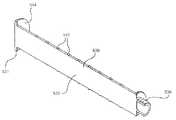
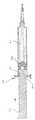
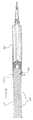
第一態様によるシリンジ組立体は、シリンジバレル内での遠位方向における、プランジャーロッドの連続的でスムースな動きを提供する要素と、脈動を提供するための要素とを組み込んでいる、プランジャーロッドおよびシリンジバレルを含む。組み立てられたシリンジは、図1〜8に分離して示された構成要素と共に、図9〜16に示される。図1〜16を参照すると、一具体例によるシリンジ組立体は、流体を保持するためのチャンバー116を画定する内表面114を有する側壁112、開放近位端111、および、そこから遠位に延びる先端115を備える遠位壁118を含む遠位端119からなる。先端115は、そこを通してチャンバー116と流体連通する流路113を含む。開放近位端111は、フィンガーフランジ120を含む。バレルの側壁112は、円筒状であり得、または、他の形状であり得る。 A syringe assembly according to the first aspect includes a plunger incorporating an element that provides continuous and smooth movement of the plunger rod in a distal direction within the syringe barrel and an element for providing pulsation. Includes rod and syringe barrel. The assembled syringe is shown in FIGS. 9-16, with the components shown separately in FIGS. Referring to FIGS. 1-16, a syringe assembly according to one embodiment extends
バレルの先端115は、先端を同軸で囲む、ルアースリップ結合部(不図示)またはルアーロック式カラー(不図示)を含み得る。カラー(不図示)は、その上に、少なくとも一つの螺子部を有する内表面を含み得る。近位端、遠位端、および、そこを通るルーメンを有するカニューレを含む針組立体(不図示)は、また、任意に提供され得る。空所を含む開放近位端および遠位端を有するハブ(不図示)は、カニューレの近位端に取り付けられ得、その結果、ルーメンは、ハブの空所と流体連通する。針組立体(不図示)は、ハブの空所へのバレルの先端の結合を介して、バレルの先端に取り外し可能に取り付けられ、その結果、ルーメンは、バレルの室と流体連通する。バレルのチャンバー116は、所望量の洗浄用溶液を含み得る。側壁112は、チャンバー116内に含まれる洗浄用溶液の量を示す計測用の指標(不図示)を含み得る。 The
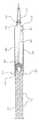
プランジャーロッド130が用意され、近位端131および遠位端139を有する、細長い本体部分132を含む。プランジャーロッド130は、チャンバー116から流体を送り出すために、バレル110のチャンバー116内で滑動可能である。プランジャーロッドの細長い本体部分132は、バレルの開放近位端111から外方に延び、チャンバー116内に配置され得る。プランジャーロッド130は、近位端131のサムプレス144と遠位端139のストッパー140を含む。ストッパー140は、バレルの内表面114とでシールを形成するシールエッジ142を含む。プランジャーロッドの形は、異なる形を有する側壁を備えたバレル内に適合するように改良され得る。 A
一つ以上の具体例のストッパー140は、プランジャーロッドの遠位端139に一体に形成されるか、プランジャーロッドの遠位端139に結合される分離要素を形成し得る。プランジャーロッドの遠位端139は、一体に形成されたストッパー(不図示)を含み得る。ストッパー140は、円錐状の遠位表面を含み、バレルは、その遠位壁に円錐状の内表面を含み得る。ストッパー140は、流体をチャンバーに引き込み、チャンバーから流出させるために、バレルの内表面114と水密係合して滑動可能に位置づけられる。もし、シリンジ組立体が製造者によって事前充填されると、ストッパーは、バレル流体を引き込むために使用される必要がないか、引き込むことが可能である必要がない。 One or more embodiments of the
ストッパー140は、バレルの内表面114とのシールを提供するために適切な、どの材料からも作成され得る。例えば、ストッパー140は、熱可塑性エラストマー、天然ゴム、合成ゴムまたは熱可塑性材料およびそれらの複合材から形成され得る。ストッパー140は、互いに結合された同一または異種材料から一体に形成されるか、または、分離した構成要素から構成され得る。プランジャーロッド130は、ポリプロピレン、ポリエチレンおよびその類似物のような、ストッパーより剛体の材料から形成され得る。材料は、使用される治療と適合するように選択され得る。 The
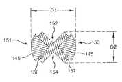
プランジャーロッドの細長い本体部分132は、本体部分の周りの周囲部分と近位端131から遠位端139まで延びる軸方向の長さを形成する、外表面134を含む。本体部分132は、円筒状または他の形状を有し得る、単一のビームまたは形態を含み得る。図1〜3に示されるように、本体部分132は、2つの直交するビーム136、137によって形成され得る。ビームは、矩形断面を有し得る。示された具体例において、2つの交差するビーム136、137は、バレルの内表面114に面し、プランジャーロッドの近位端131から遠位端139まで、軸方向長さに沿って延びる、四分円151、152、153、154(図5により明確に示される。)を輪郭として描く外表面を形成するように交差する。 The
図1〜6に示された具体例において、一つ以上のパルス要素が、プランジャーロッドの本体部分132の外表面およびバレルの内表面114に配置される。パルス要素は、一体に形成されるか、プランジャーロッドおよび/またはバレルに付け加えられる分離要素として用意され得る。プランジャーロッド130またはバレル110は、分離したパルス要素の取り付けのための態様をさらに含み得る。図1〜3に示された具体例によれば、一つ以上のパルス要素は、ディスク145またはリブ部材の形状で、複数の延長部として用意される。そのような具体例において、ディスク145は、プランジャーロッドの本体部分132の外表面に配置される。本体部分132が、2つの交差するビーム136、137を有する具体例において、ディスク145は、隣接するビーム136、137に結合され、四分円からバレルの内表面に向けて放射方向外方に延びる。示された具体例において、ディスク145は、2つの隣接していない四分円151、153から形成され、ビーム136、137に結合される。本体部分132が単一ビームを含む具体例において、ディスク145は、プランジャーロッド130の外表面134の一区分または一部分に沿って周囲に形成され、バレルの内表面114に向かって放射方向外方に延び得る。プランジャーロッドの外表面134は、ディスク150または他の延長部を持たない区分または部分を含み得る。特定の具体例において、2つのディスクがプランジャーロッドの外表面の2つの対向する区分に沿って周囲に形成され、ディスクのないプランジャーロッドの外表面の2つの対向する区分を残し得る。ディスク145は、プランジャーロッドの長さに沿って規則的な間隔で配置され得る。一つ以上の代替例において、ディスク145は、不規則な間隔で配置され得、および/または、プランジャーロッドの近位端131または遠位端139に、または、近接して、配置され得る。 In the embodiment shown in FIGS. 1-6, one or more pulse elements are disposed on the outer surface of the plunger
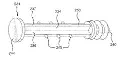
図4〜6は、プランジャーロッド230の代替具体例を示す。プランジャーロッド230は、近位端231から遠位端239まで延びる細長い本体部分232を備えた、近位端231および遠位端239を含む。プランジャーロッド230の遠位端239は、シールエッジ242を備えたストッパー240を含み、近位端239は、サムプレス244を含む。プランジャーロッドの細長い本体部分232は、本体部分の周りの周囲部分と近位端231から遠位端239まで延びる軸方向長さを形成する、外表面234を含む。示された具体例において、本体部分232は、2つの直交するビーム236、237によって形成される。ビームは、矩形断面を有し得る。図4〜6に示された具体例において、一つ以上のパルス要素が、プランジャーロッド230の外表面に配置された突起245の形状で用意される。一つ以上の突起245は、バレルの内表面214に向かって放射状に外方に広がる。一つ以上の突起245は、プランジャーロッドの本体部分の周囲部分の一部に限定され、突起または延長部分を有しないプランジャーロッドの周囲部分の残りの部分250を残す。図4〜6に示されるように、複数の突起245が、プランジャーロッドの軸方向長さに沿って配置され、軸方向長さに沿って予め決められた間隔で配置され得る。特定の具体例において、予め決められた間隔は、均等に間隔をあけられる。 4-6 illustrate alternative embodiments of the
2つの直交するビーム236、237を用いる具体例において、突起245は、図6に示されるように、一つのビームの対向端に配置され得る。本体部分を形成する単一のビームを用いる具体例において、一つ以上の突起245は、プランジャーロッドの外表面234の一区分に沿って周囲に形成され、残りの外表面の区分は、突起245または他の延長部分をもたない。特定の具体例において、突起は、プランジャーロッドの外表面234の2つの対向する区分に沿って周囲に形成され、突起のないプランジャーロッドの外表面234の2つの対向する区分を残し得る。突起245は、プランジャーロッドの長さに沿って規則的な間隔で配置され得る。一つ以上の代替具体例において、突起245は、不規則間隔で配置され、および/または、プランジャーロッドの近位端231または遠位端239に、または、近接して、配置され得る。 In an embodiment using two
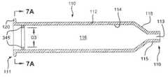
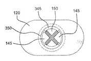
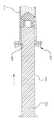
一つ以上のパルス要素が、また、バレルの内表面に配置され得る。図7〜8に示された具体例において、要素は、バレル110の内表面114に配置され、チャンバーおよび/またはプランジャーロッドに向けて放射方向内方に延びる保持リング345の形で用意される。保持リング345は、プランジャーロッドに配置されたパルス要素、例えば、ディスク145および/または突起245と相互作用し、プランジャーロッド230がバレル内を遠位方向に移動するときに、プランジャーロッド230の脈動を提供する。そのような具体例において、保持リング345は、バレルの内表面114によって形成される断面の幅に比較して、より狭い断面の幅を形成する。保持リング345は、保持リングよりも大きい断面を有する拡張断面部分を画定する、少なくとも一つの開口部350を含み得る。バレルの内表面114は、保持リング345において、開口部350よりも小さな断面幅を有する。少なくとも一つの開口部350は、何の拡張部分をも有さず、プランジャーロッドと相互作用しない、バレルの内表面の一部を形成する。特定の具体例において、2つ以上の保持リング345が、バレルの内表面114の長さに沿って予め決められた間隔で配置され得る。代替具体例は、2つの保持リングと各々のリングにおける2つの開口部、三つの保持リングと各々のリングにおける2つの開口部、三つのリングと三つの開口部、および、保持リングと開口部の他の組み合わせを含み得る。バレルの内表面およびプランジャーロッドの外表面に配置された要素は、互いに協働し得るように形成され得ることが理解されるであろう。さらに特定の具体例において、保持リングが配置される予め決められた間隔は、バレルの内表面の長さに沿って規則的な間隔をあけられる、または、代わって、バレルの内表面の長さに沿って不規則な間隔をあけられる。 One or more pulse elements may also be disposed on the inner surface of the barrel. In the embodiment shown in FIGS. 7-8, the elements are provided in the form of retaining
代替具体例によれば、一つ以上のパルス要素が、バレルの内表面に沿って周囲に形成される代わりに、離れた点に形成される。そのような具体例は、パルス要素を有さず、プランジャーロッド130と相互作用しない、バレルの内表面114の部分を含む。そのような離れた要素は、バレルの内表面の長さに沿って予め決められた間隔で配置され得、さらに特定の具体例において、予め決められた間隔は、バレルの内表面の長さに沿って均等に間隔をあけられる。 According to an alternative embodiment, one or more pulse elements are formed at remote points instead of being formed around the inner surface of the barrel. Such an embodiment includes a portion of the
使用中、使用者は、所望の動きを選択するために、プランジャーロッドの拡張部分および/または突起とシリンジバレルとを、それぞれ整列させる。例えば、もし、脈動が望まれるなら、使用者は、プランジャーロッドおよび/またはシリンジバレルを回転させ、その結果、プランジャーロッドに配置された一つ以上のパルス要素は、バレルの内表面に配置されたパルス要素または分離した構成要素としてバレルに備えられたパルス要素(以下により詳細に説明される。)と相互作用する。スムースな洗浄技術に起因する動きのような、連続的でスムースな動きが望まれるなら、使用者は、プランジャーロッドに配置された一つ以上のパルス要素が、バレルに配置された一つ以上のパルス要素と相互作用しないように、プランジャーロッドおよび/またはシリンジバレルを回転させる。 During use, the user aligns the plunger rod extension and / or protrusion with the syringe barrel, respectively, to select the desired movement. For example, if pulsation is desired, the user rotates the plunger rod and / or syringe barrel so that one or more pulse elements disposed on the plunger rod are disposed on the inner surface of the barrel. Interacts with a pulsed element or a pulsed element provided in the barrel as a separate component (described in more detail below). If continuous and smooth movement is desired, such as movement due to a smooth cleaning technique, the user can use one or more pulse elements located on the plunger rod, one or more located on the barrel. Rotate the plunger rod and / or syringe barrel so that it does not interact with any pulsing element.
特に、図9を参照すると、プランジャーロッド130に脈動を提供するため、ディスク145が、保持リング345と整列され、その結果、バレル内に含まれる洗浄溶液を放出するために、力が、プランジャーロッドに対し遠位方向に適用されるとき、ディスク145と保持リング345との間の相互作用が存在する。図11を参照すると、プランジャーロッド230の突起245は、シリンジバレルの保持リング345と整列され、その結果、バレル内に含まれる洗浄溶液を放出するため、力が、プランジャーロッドに対し遠位方向に適用されるときに、突起245と保持リング345との間の相互作用が存在する。 In particular, referring to FIG. 9, in order to provide pulsation to the
一つ以上の具体例において、一つ以上のパルス要素が、シリンジバレルと一緒の使用のために、分離した構成要素として提供される。分離した一つ以上のパルス要素は、ここに説明されるか、または、そうでないプランジャーロッドと一緒に脈動を提供するための、どの態様も含まない、標準のシリンジバレルと共に利用され得る。そのようなシリンジバレルは、上述した保持リング345のような、どんな内方突起も有さないようにできる。 In one or more embodiments, one or more pulse elements are provided as separate components for use with a syringe barrel. One or more separate pulse elements can be utilized with a standard syringe barrel that does not include any embodiment for providing pulsation with a plunger rod as described herein or otherwise. Such a syringe barrel can be free of any inward protrusions, such as the retaining
図17〜28は、シリンジバレルの開放近位端に配置され得る第一パルス要素400を示す。特に、第一パルス要素400は、シリンジバレルの開放近位端に取り付けるために結合する上部部分410および下部部分412を含む。示された具体例において、上部部分410および下部部分412は、シリンジバレルの開放近位端の周りを囲む、外郭または部分的な囲いを形成する。第一パルス要素400は、ここに説明されるように、シリンジバレルを取り囲む開口を含む。示された具体例において、上部部分410および下方部分412は、全く同じである。しかしながら、上部部分410および下方部分412は、また、互いに異なり得ることが理解される。上部部分410および下方部分412は、シリンジバレルに垂直に配置された外郭壁414を含む。外郭壁414は、遠位壁415および近位壁416を含む。外郭壁は、また、図22に示されるように、頂端417、底端418、第一端419および第二端420を含む。上部部分410および下方部分412は、また、外郭壁414の第一端419および第二端420に配置された、2つの側壁422を含む。側壁422は、遠位側424、近位側426、および、シリンジバレルの近位端に第一パルス要素400を固定するための周縁または保持壁を形成する、少なくとも一つの入れ子要素を含む。示された具体例において、パルス要素400は、双方の側壁422の遠位側424および近位側426に配置された2つの入れ子要素428を含む。図22に示された具体例における入れ子要素428は、パルス要素400の開口に向けて内方に延びる、L型壁を含む。 FIGS. 17-28 show a
図22により明確に示されるように。外郭壁414は、底端418に部分的な開口430を含む。上部部分410および下方部分412が、シリンジバレルの近位端の周りに結合されたとき、上部部分410の部分的な開口430、および、および下方部分412の部分的な開口430は、プランジャーロッドを受け入れ、バレルの開放近位端を取り囲む、完全な開口432を形成する。完全な開口432は、上部部分410の底端418から下方部分412の底端までで計測される場合、より小さな断面幅部分445を有する。より小さな断面幅部分は、プランジャーロッドに配置された一つ以上のパルス要素で計測される場合の、ここに説明されるプランジャーロッドの断面幅より小さい。完全な開口432は、上部部分410および下方部分412の結合部で計測されると、プランジャーロッドに配置された一つ以上のパルス要素で計測される場合の、ここに説明されるプランジャーロッドの断面幅より大きい、より大きな断面幅部分450を有する。上部部分410および下方部分412によって形成された完全な開口434の底端418と、ここに説明されるプランジャーロッドの一つ以上のパルス要素との間の相互作用は、プランジャーロッドがバレル内を遠位方向に移動するとき、プランジャーロッドに脈動を提供する。 As more clearly shown in FIG. The outer wall 414 includes a
図17〜28に示されるように、第一パルス要素400は、シリンジバレル510およびプランジャーロッド530と共に使用される。シリンジバレル510は、開放近位端511、遠位端519、および、遠位端519から近位端511に延びる側壁512を含む。側壁512は、流体を保持するチャンバー516を画定する内表面514を含む。遠位端519は、そこから遠位に延びる、先端515を備えた遠位壁518を含む。先端515は、そこを通ってチャンバー516と流体連通する流路517を含む。先端515は、そこに取り付けられる先端キャップ513を含み得る。開放近位端511は、フィンガーフランジ520を含む。バレルの側壁512は、円筒状または他の形状であり得、チャンバー内に突出するいかなる形状も有さないことができる。 As shown in FIGS. 17-28, the
シリンジバレル510にパルス要素400を組み付けるために、上部部分410および下方部分412が、フィンガーフランジ520の周りに結合される。特に、フィンガーフランジ520は、上部部分410および下方部分412が、互いに、結合されるか、または、接触またはほぼ接触となるとき、上部部分410および下方部分412の入れ子要素428内に挿入される。上部部分410および下方部分412は、図17に示されるように、摩擦縛り嵌めによってフィンガーフランジ520に取り付けられる。他の取り付け機構、例えば、スナップ嵌め、協働縦溝、接着取り付け、および、同等のものが用いられることが理解されるであろう。 To assemble the
図17〜20に示されたプランジャーロッド530は、近位端531および遠位端539を含み、近位端531から遠位端539に延びる細長い本体部分532を備える。プランジャーロッド530の遠位端539は、シールエッジ542を備えたストッパー540を含み、近位端531は、サムプレス540を含む。プランジャーロッドの細長い本体部分532は、本体部分の周囲と、近位端531から遠位端539に延びる軸方向長さを形成する、外表面534を含む。示された具体例において、本体部分532は、2つの直交するビーム536、537によって形成される。ビームは、矩形の断面を有し得る。図18〜20に示された具体例において、一つ以上のパルス要素が、プランジャーロッド530の外表面に配置された突起545の形で提供される。一つ以上の突起545は、バレルの内表面に向かって外方に延びる。示された具体例において、突起545は、ビーム536の一端上の半円または部分的リブを形成する。 The
一つ以上の突起545は、プランジャーロッドの本体部分の周囲の一部に限定され、プランジャーロッドの本体部分の周囲の残りの部分550には、突起がない。特に、突起545は、ビーム536の対向端に配置され、一方、ビーム537の対向端は、いかなる突起も有さず、いかなる突起も有さないプランジャーロッドの部分550として表される。図18〜20に示されるように、複数の突起545が、プランジャーロッドの軸方向長さに沿って配置され得、軸方向に沿った予め定められた間隔で配置され得る。特定の具体例において、予め定められた間隔は、均等に間隔をあけられる。 The one or
本体部分を形成する単一のビームを使用する具体例において、一つ以上の突起545は、プランジャーロッドの外表面534の一区分に沿って形成され、一方、外表面の残りの区分は突起545または他の延長部を有さない。特定の具体例において、突起は、また、プランジャーロッドの外表面534の二つの対向した区分に沿って周囲に形成され得、突起を有さないプランジャーロッドの外表面534の区分を残す。突起545は、プランジャーロッドの長さに沿って規則的な間隔で配置される。一つ以上の代替具体例において、突起545は、不規則な間隔で配置され得、および/または、プランジャーロッドの近位端531または遠位端539に、または、近接して配置され得る。 In embodiments using a single beam forming the body portion, one or
使用時、プランジャーロッド530は、第一パルス要素400の完全な開口434を通してシリンジバレル510のチャンバー516に挿入される。プランジャーロッドの突起545は、プランジャーロッドに脈動を提供するため、完全な開口432のより小さい断面幅554と整列させられ得る。図24Aに示されるように、プランジャーロッドの連続的で、スムースな移動を提供するために、突起545が完全な開口532のより大きい断面幅450と整列させられるように、使用者は、プランジャーロッド530を回転し得る。 In use, the
第一パルス要素400の上部部分410および下方部分412は、バレル内におけるプランジャーロッドの脈動又は連続的でスムースな移動を可能にするように変更され得る。一つ以上の具体例において、上部部分410および下方部分412は、バレルに取り付けられるとき、上部部分410および下方部分412の底端418における完全な開口の断面幅が、上部部分410および下方部分412の結合時における完全な開口432の断面幅よりも大きいように位置決めされ得る。換言すると、上方部分410は、完全な開口432の断面幅を増大させるために、各々の部分の底部418間に空間を加えるように、下方部分412から距離を置いて位置決めされる。一つ以上の代替具体例において、上部部分410または下方部分412の少なくとも一つの部分開口430は、プランジャーロッドの突起545が、第一パルス要素400を遠位に滑動させ得るように、内方に延びるノッチ(不図示)を含み得る。プランジャーロッドが本体部分532の対向端に突起545を含むなら、上部部分410および下方部分412の双方は、ノッチを含み得る。そのような具体例において、完全開口432は、ノッチにおける拡大された断面幅を有し、円形で、一定の断面幅を有し得る。完全開口432の一定の断面幅が、突起545と整列させられるとき、第一パルス要素400は、プランジャーロッドの脈動を提供するため、突起545と相互作用または係合する。上部部分410、および/または、下方部分412の一つのノッチ又は複数のノッチが、突起545と整列させられるとき、ノッチにおける完全開口432の拡大された断面幅は、プランジャーロッドの連続的な、および、スムースな移動を提供するため、第一パルス要素と相互作用または係合することなく、プランジャーロッドが第一パルス要素400を超えて遠位方向へ移動するのを可能にする。他の変形例において、上部部分410および下方部分412の少なくとも一つの部分開口430は、プランジャーロッドの本体部分に沿って配置された複数の刻み目(不図示)を有するプランジャーロッドと協働する外方に延びるノッチ(不図示)を含み得る。プランジャーロッドが本体部分の対向端に複数の刻み目を含むなら、上部部分410および下方部分412の双方は、外方に延びるノッチを含み得る。複数の刻み目で計測されたプランジャーロッド本体の断面幅は、どんな刻み目も含まない他の場所におけるプランジャーロッド本体の断面幅より小さくあり得る。プランジャーロッドおよび/または第一パルス要素400は、外方に延びるノッチと、プランジャーロッドの突起545を可能にする複数の刻み目を整列させるために回転させられ、その結果、複数の刻み目が、プランジャーロッドが第一パルス要素を超えて遠位に滑動するのを可能にする。そのような具体例において、完全な開口432は、外方に延びるノッチにおける狭められた断面幅を備え、円形であり、一定の断面幅であり得る。完全な開口の狭められた断面幅が、どの刻み目も有しないプランジャーロッドの部分と整列させられると、第一パルス要素は、プランジャーロッドの脈動を提供するため、プランジャーロッドと相互作用または係合する。上部部分410、および/または、下方部分412の外方に延びる一つのノッチまたは複数のノッチが、複数の刻み目と整列させられると、複数の刻み目におけるプランジャーロッドの狭められた断面幅は、外方に延びるノッチと適合し、プランジャーロッドの連続的でスムースな移動を提供するため、第一パルス要素と相互作用または係合することなく、プランジャーロッドが第一パルス要素を超えて遠位に移動するのを可能にする。 The
一つ以上の具体例は、シリンジバレルと一緒の使用のための分離構成部品として提供され得る、第二パルス要素600を含み得る。そのような具体例において、分離された一つ以上のパルス要素は、ここで、または、別に説明されるプランジャーロッドと共に脈動を提供するためのどんな態様も含まない標準のシリンジバレルと共に使用され得る。そのようなシリンジバレルは、上述の保持リング345のような、どんな内方突起も有さないことができる。 One or more embodiments can include a
図29〜33は、シリンジバレルの開放近位端に隣接して配置された第二パルス要素600を示す。特に、第二パルス要素600は、開放遠位端、開放近位端、および、それらを通る開口612を有する回転体610を含む。第二パルス要素600は、図17〜28に示されたプランジャーロッド530、および、どんなパルス要素も持たない例示的なシリンジバレル620と共に示される。シリンジバレル620は、開放近位端621、遠位端629、および、遠位端629から近位端621に延びる側壁622を含む。側壁622は、流体を保持するためのチャンバー626を画定する内表面624を含む。遠位端629は、そこから遠位に延びる先端625を備えた遠位壁628を含む。先端625は、そこを通してチャンバー626と流体連通する流路627を含み、そこに取り付けられる先端キャップ623を含む。開放近位端621は、フィンガーフランジ630を含む。バレルの側壁622は、円筒状であり得、また、他の形状であり得、チャンバー内に突出するいかなる構造も有さない。開放近位端621は、第二パルス要素をシリンジバレルの開放近位端621に取り付けるための取り付け構造を含む。 FIGS. 29-33 show a
回転可能体610が、シリンジバレルの開放近位端621に取り付けられるとき、それは、シリンジバレルの側壁622に垂直に位置決めされ、または、フィンガーフランジ630に平行である。回転可能体610は、回転可能体610をシリンジバレルの近位端に取り付けるための遠位方向に延びるアタッチメント部分(不図示)を含み得る。例えば、遠位方向に延びるアタッチメント部分は、バレルの開放近位端でバレルの内表面と摩擦締まり嵌めを形成し得る。回転可能体610を取り付けるための他の構造が使用され得るが、そのような構造は、回転するための回転可能体の能力を妨げるべきでない。開口612は、卵形を有し、互いに対向する第一点614および第二点615、ならびに、互いに対向する第三点616および第四点617を含む。第一点614と第二点615との距離は、第三点616と第四点617との距離より大きい。第三点616から第四点617までで計測された開口部612の断面幅は、狭められた断面幅645である。第一点614から第二点615までで計測された開口部612の断面幅は、拡大された断面幅650である。回転可能体610は、開口612の形状と類似の形状を有し得る。したがって、回転可能体610の位置は、以下でより詳細に説明されるように、プランジャーロッドに対する開口612の位置を示す。 When the
使用時、プランジャーロッド530は、回転可能リングの開口を通してチャンバー626に挿入される。回転可能リングは、図28に示されるように、狭められた断面幅部分645と整列させられたプランジャーロッド530の突起545と共に、パルス位置に位置決めされる。この配置において、狭められた断面幅部分645と突起545は、プランジャーロッドがバレル内を遠位方向に移動するとき、プランジャーロッドに脈動を提供する。この位置において、図28に示されたように、回転可能体610は、フィンガーフランジに対して90度に位置決めされる。この位置は、プランジャーロッド530および第二パルス要素600がパルス位置に位置付けられたことの視覚的な表示として機能し得る。回転可能体610は、回転させられることが可能で、図31に示されるように、突起545が拡大された断面幅部分645と整列させられる非パルス位置に位置付けられる。この配置において、プランジャーロッドがバレル内を遠位方向に移動するとき、プランジャーロッドに脈動を提供する、拡大された断面幅部分645と突起545との相互作用はないだろう。この位置において、回転可能体610は、フィンガーフランジと整列して位置付けられる。この位置は、プランジャーロッド530と第二パルス要素が非パルス位置に位置付けられたことの視覚的な表示として機能し得る。 In use, the
一つ以上の具体例において、プランジャーロッドは、バレル内で回転可能に配置されるか、換言すると、回転することができるようにバレル内に配置される。上述したとおり、プランジャーロッドおよび/またはバレルの形状は、少なくとも部分的にバレル内に配置されたとき、プランジャーロッドの回転を可能とするように変更され得る。回転量は、また、プランジャーロッドおよび/またはバレルのいずれかの形状を変更することによって制限され得る。バレル内のプランジャーロッドの回転は、使用者が、バレル内でのプランジャーロッドの移動のために、脈動または連続的でスムースな移動のいずれかを選択することを可能とする。図9〜10に示された具体例において、プランジャーロッド130は、脈動と、ディスク145を保持リング345の開口またはどの要素も有さないバレルの内表面の部分とを整列させることによる、連続的でスムースな移動とを切り替えるために、90度回転させられる。代わって、使用者は、図13〜14により明確に示されるように、ディスクを有さないプランジャーロッドの部分150を保持リング345と整列させるために、プランジャーロッド130を90度回転させることができる。当業者は、回転量がプランジャーロッドおよび/またはシリンジバレルに使用される要素の数、大きさおよび位置に依存することを認識するであろう。例えば、一つのディスクが、プランジャーロッドの四分円に、プランジャーロッドの軸方向長さに沿った一つ以上の位置で配置されている場合、使用者は、90度以上プランジャーロッドを回転させる必要があり得る。 In one or more embodiments, the plunger rod is rotatably disposed within the barrel, or in other words, disposed within the barrel such that it can rotate. As described above, the shape of the plunger rod and / or barrel can be altered to allow rotation of the plunger rod when placed at least partially within the barrel. The amount of rotation can also be limited by changing the shape of either the plunger rod and / or the barrel. The rotation of the plunger rod within the barrel allows the user to select either pulsating or continuous and smooth movement for movement of the plunger rod within the barrel. In the embodiment shown in FIGS. 9-10, the
一つのビームの対向端に配置された2つの突起を有する、プランジャーロッド230の代替具体例(図4〜6に示される。)が、図11〜12に、バレル内に挿入されて示される。プランジャーロッド230は、突起245を、保持リング350の開口、または、どの要素も有さないバレルの内表面の部分と整合させるために、90度回転させられねばならない。代わりに、使用者は、図15〜16により明確に示されるように、突起を有さないプランジャーロッドの部分250を保持リング3454と整列させるために90度回転させ得る。 An alternative embodiment of the plunger rod 230 (shown in FIGS. 4-6) having two protrusions located at opposite ends of one beam is shown inserted in the barrel in FIGS. . The
図26〜27に示された具体例において、プランジャーロッド530は、突起545を第一パルス要素400のより大きな断面幅部分450と整列させるために90度回転させられ得る。代わりに、使用者は、突起のないプランジャーロッドの部分550を第一パルス要素のより小さな断面幅部分445と整列させるために90度回転させ得る。図28に示された具体例において、プランジャーロッド530は、突起545を第二パルス要素500の拡大された断面幅部分650と整列させるために90度回転させられ得る。代わりに、使用者は、突起のないプランジャーロッドの部分550をパルス要素の狭められた断面幅部分645と整列させるために、プランジャーロッド530を、90度回転させ得る。 In the embodiment shown in FIGS. 26-27, the
プランジャーロッドの外表面の周囲部分に沿って一つの要素のみが配置される場合、脈動と連続的でスムースな移動との間の切り替えは、より大きな回転を必要とし得る。プランジャーロッドの外表面の周囲の部分に沿って配置された複数の要素を利用する具体例において、連続的でスムースな移動に対し、プランジャーロッドの要素と要素を有さないバレルの部分とを整列させるため、または、バレルの内表面に配置された要素と要素を有さないプランジャーロッドの部分とを整列させるため、より少ない回転が必要とされることが理解さえるであろう。 If only one element is placed along the peripheral portion of the outer surface of the plunger rod, switching between pulsation and continuous smooth movement may require greater rotation. In an embodiment utilizing a plurality of elements disposed along a peripheral portion of the outer surface of the plunger rod, the plunger rod element and the non-elemented barrel portion for continuous and smooth movement; It will be appreciated that less rotation is required to align the elements or to align the elements disposed on the inner surface of the barrel with the portions of the plunger rod that do not have elements.
図3および図6に、より明確に示されるように、一つ以上のパルス要素を含む箇所(例えば、図3および図6の、それぞれ、ディスク145および突起245)で計測された断面幅D1は、どの要素も有さない箇所で計測されたプランジャーロッドの断面幅D2より大きい。図7および図8を参照すると、どの要素(例えば、保持リング345)も有さない内表面の部分から計測されたバレル内表面の断面幅D4は、バレルの内表面に配置された保持リング345の箇所で計測されたバレルの内表面の断面幅D3より大きい。プランジャーロッドとバレルの要素が整列させられると、プランジャーロッドのより大きい断面幅D1、および、減少した断面幅D2は、遠位方向に滑動するプランジャーロッドとバレルの内表面に配置された要素との間で、機械的干渉における変動を引き起こす。 As shown more clearly in FIGS. 3 and 6, the cross-sectional width D1 measured at a location containing one or more pulse elements (eg,
連続的でスムースな移動が選択されたとき、プランジャーロッドに配置された要素(例えば、それぞれ、図3および図6のディスク145および突起245)は、いかなる要素も有しないバレルの内表面の部分(例えば、図8の参照数字350)と整列させられる。換言すると、プランジャーロッドの要素が、いかなる要素も有さないバレルの内表面の部分と整列させられると、バレルの内表面の拡大された断面幅D4は、プランジャーロッドの拡大された断面幅D1が、機械的干渉において、いかなる増大または変化もなく、遠位方向に進むことを可能にする。 When continuous and smooth movement is selected, the elements disposed on the plunger rod (eg,
同様に、バレルの内表面に配置された要素(例えば、保持リング350)が、要素を有さないプランジャーロッドの部分(例えば、図3の参照番号150、および、図6の参照番号250)と整列させられるとき、プランジャーロッドとバレル間で、連続的でスムースな移動が許容される。換言すると、バレルの要素(例えば、保持リング350)が、要素を有さないプランジャーロッドの部分(例えば、図3の参照番号150、および、図6の参照番号250)と整列させられるとき、プランジャーロッドの減少した断面幅は、プランジャーロッドとバレルとの間の機械的干渉において、いかなる重大なまたは付加的な変化もなく、バレルの要素を超えて遠位方向に、バレル内を進行することを許容される。 Similarly, an element disposed on the inner surface of the barrel (eg, retaining ring 350) is a portion of the plunger rod that does not have an element (eg,
プランジャーロッドに配置されたパルス要素(すなわち、ディスク145、突起245および/または突起545)と、バレルに配置されるか、分離片としてバレルに取り付けられたパルス要素(すなわち、保持リング345、より小さい断面幅部分445および/または狭められた断面幅部分645)との相互作用は、プランジャーロッドの遠位方向への移動に抵抗を与える。プランジャーロッドのパルス要素が、バレルのパルス要素を乗り越えることができるように、プランジャーロッドに追加の機械力が適用されると、バレルのパルス要素を過ぎるプランジャーロッドのパルス要素の進行は、プランジャーロッドがバレル内で遠位方向に移動する際、プランジャーロッドとバレルとの間の干渉に変化をもたらす。プランジャーロッドのパルス要素(すなわち、ディスク145、突起245および/または突起545)が、もはや、バレルのパルス要素(すなわち、保持リング345、より小さい断面幅部分445および狭められた断面幅部分645)と整列させられない場合、プランジャーロッドのパルス要素とバレルのパルス要素との間の相互作用はなく、したがって、プランジャーロッドとバレルとの間の干渉における相互作用または変化はない。 A pulse element (ie,
一つ以上の具体例において、プランジャーロッドおよび/またはバレルは、脈動または連続的でスムースな移動が選択されるとき、プランジャーロッド、バレルおよび/またはバレルの回転体のさらなる回転を防止する錠止構造を含み得る。一つ以上の具体例において、錠止構造は、バレルまたは保持リングの内表面、および/または、プランジャーロッドの外表面における増大した摩擦表面(不図示)を含み得、ここに説明された洗浄シリンジ組立体の通常の使用中に普通に経験されるより大きな、互いに対する、プランジャーロッド、バレルおよび/または回転体を回転させる力を適用することを、使用者に要求する。一つ以上の具体例において、バレルおよび/または回転体の内表面は、プランジャーロッドの外表面に配置された一つ以上のパルス要素を受け入れ、保持する、ギザギザ状の部分(不図示)を含み得る。ギザギザ状の部分(不図示)は、一つ以上のパルス要素の箇所において、プランジャーロッドの拡大された断面幅に対応する、拡大された断面幅を提供するだろう。ギザギザ状の部分(不図示)は、また、使用者が、プランジャーロッド、バレルまたは回転体を積極的に回転させるために、プランジャーロッド、バレルまたは回転体に、より大きな回転力を適用することを必要とするであろう、意図しない回転を妨げるための物理的な障壁を提供するであろう。要求される回転力は、ここに説明される洗浄シリンジ組立体の通常の使用中に生じる可能性がある回転力より大きいであろう。 In one or more embodiments, the plunger rod and / or barrel is a lock that prevents further rotation of the plunger rod, barrel and / or barrel rotator when pulsation or continuous and smooth movement is selected. A stop structure may be included. In one or more embodiments, the locking structure can include an increased friction surface (not shown) on the inner surface of the barrel or retaining ring and / or the outer surface of the plunger rod, as described herein. Requires the user to apply greater force to rotate the plunger rod, barrel and / or rotor relative to each other than is normally experienced during normal use of the syringe assembly. In one or more embodiments, the inner surface of the barrel and / or rotating body includes a jagged portion (not shown) that receives and holds one or more pulse elements disposed on the outer surface of the plunger rod. May be included. The jagged portion (not shown) will provide an enlarged cross-sectional width corresponding to the enlarged cross-sectional width of the plunger rod at one or more pulse element locations. The jagged portion (not shown) also applies a greater rotational force to the plunger rod, barrel or rotor to allow the user to actively rotate the plunger rod, barrel or rotor. It will provide a physical barrier to prevent unintentional rotation. The required rotational force will be greater than the rotational force that can occur during normal use of the cleaning syringe assembly described herein.
使用中、ここに説明されたシリンジ組立体は、ニードル組立体と結合され、公知の方法を使用して洗浄液で満たされる。また、シリンジ組立体は、製造者または供給者から事前に充填されて提供され得る。洗浄液は、VADの洗浄または性能維持のために意図されたいかなる溶液でもあり得る。例示的な洗浄液は、生理食塩水洗浄液、および/または、ヘパリンロック洗浄液を含む。これらの溶液は、当該技術分野において知られており、容易に利用可能である。生理食塩水洗浄液の一例は、0.9%の注射用塩化ナトリウム(米国薬局方)である。ヘパリンロック洗浄液の一例は、1ml当り100ユニット(米国薬局方)のヘパリンナトリウム、または、1ml当り10ユニット(米国薬局方)のヘパリンナトリウムを有する、0.9%の塩化ナトリウムである。ニードル組立体に取り付けられると、シリンジ組立体は、穿刺可能なセプタム、または、洗浄液を含むバイアルまたはガラスアンプルの首部のプレスプリットセプタムに挿入され得るブラントカニューレを貫通するために使用され、洗浄液は、ニードルカニューレを通してチャンバー内に流体を引き込むため、バレルを保持しながら、プランジャーロッドを近位方向に引っ張ることによって、シリンジバレル内に引き込まれる。代わりに、シリンジの組立中または後に、殺菌充填法を使用して、多数の洗浄シリンジが洗浄液で事前に満たされる。そのような事前充填シリンジは、バレルの流路113をシールする先端キャップ(不図示)を備えて供給され得る。先端キャップは、天然および合成ゴム、熱可塑性エラストマーまたはそれらの組み合わせのような、熱可塑性材料およびエラストマー材料からなる群から選択される材料から形成され得る。一旦組立てられると、シリンジ組立体は、I.VセットのカテーテルのようなVADを洗浄するのに使用され得る。 In use, the syringe assembly described herein is combined with a needle assembly and filled with a cleaning solution using known methods. Also, the syringe assembly can be provided pre-filled from the manufacturer or supplier. The cleaning solution can be any solution intended for cleaning or maintaining performance of the VAD. Exemplary cleaning solutions include a saline cleaning solution and / or a heparin lock cleaning solution. These solutions are known in the art and are readily available. An example of a saline wash is 0.9% sodium chloride for injection (US Pharmacopeia). An example of a heparin lock wash solution is 0.9% sodium chloride with 100 units (USP) heparin sodium per ml or 10 units (USP) heparin sodium per ml. When attached to the needle assembly, the syringe assembly is used to penetrate a pierceable septum, or a blunt cannula that can be inserted into a pre-split septum at the neck of a vial or glass ampoule containing the cleaning solution, To draw fluid into the chamber through the needle cannula, it is drawn into the syringe barrel by pulling the plunger rod proximally while holding the barrel. Instead, during or after assembly of the syringe, a number of wash syringes are prefilled with wash fluid using a sterilization filling method. Such a prefilled syringe may be supplied with a tip cap (not shown) that seals the
一つ以上の具体例において、ここに説明されたシリンジ組立体は、注入ポンプ式供給システムに組み込まれ得る。当該技術分野において知られているように、プッシュパルス式洗浄技術は、典型的には、洗浄液のゆっくりとした、制御された供給を提供するために、例えば、小児科用のセッティングに利用される、注入ポンプ式供給システムと一緒の使用には好適でない。注入ポンプ式供給システムは、圧力警報器、または、プランジャーロッドとバレル間の圧力または力の増大または変化を計測するための他の器具と協働する。したがって、プッシュパルス式の洗浄技術が注入ポンプ式供給システムに使用されると、プランジャーロッドとバレルの間の圧力または力が変化し、圧力警報器または他の器具を始動させる。そのような警報器は、注入ポンプ式供給システムが停止することをもたらし得る。ここに説明されたシリンジ組立体は、ここに説明された手動のプッシュパルス式および脈動洗浄技術のようなシリンジからの脈動流をもたらす洗浄技術に代えて、スムースな洗浄技術を反復させる連続的でスムースな移動を選択するように、プランジャーロッドおよび/またはバレルを調整することによって、注入ポンプ式供給システムおよび他の類似の圧力感知式システムに対して利用され得る。 In one or more embodiments, the syringe assembly described herein can be incorporated into an infusion pump delivery system. As is known in the art, push pulse cleaning techniques are typically utilized, for example, in pediatric settings to provide a slow and controlled supply of cleaning fluid. Not suitable for use with infusion pump delivery systems. The infusion pump delivery system works with a pressure alarm or other instrument to measure pressure or force increase or change between the plunger rod and barrel. Thus, when a push pulse cleaning technique is used in an infusion pump delivery system, the pressure or force between the plunger rod and barrel changes and triggers a pressure alarm or other instrument. Such an alarm can cause the infusion pump delivery system to shut down. The syringe assembly described herein is a continuous, repeatable smooth cleaning technique that replaces cleaning techniques that provide pulsating flow from the syringe, such as the manual push pulse and pulsating cleaning techniques described herein. It can be utilized for infusion pump delivery systems and other similar pressure sensitive systems by adjusting plunger rods and / or barrels to select smooth movement.
一つ以上の具体例によれば、プランジャーロッド、および/または、バレルの内表面に配置された一つ以上のパルス要素は、プランジャーロッドの遠位方向への移動中、シリンジバレルと干渉するか、または増大した機械的干渉を形成するように形作られる。プランジャーロッドとバレルとの間での機械的な力の変化は、使用者が、排出中、プランジャーロッドに対し、遠位方向に力を適用するとき、プランジャーロッドの動きを妨げ、緩やかにし、または、停止させる。結果として、使用者は、要素を過ぎて遠位に進めるため、プランジャーロッドに遠位方向へのより大きな力を適用しなければならない。プランジャーロッドに適用される力の変化は、流体流にパルスを与え、プランジャーロッドの脈動を形成し、洗浄液に、所望の乱流または脈流を与える。プランジャーロッドに適用される異なった力によって引き起こされる流速の変化は、さらに、洗浄液の乱流を増大させる。使用者がバレルのチャンバーから洗浄液を放出するとき、プランジャーロッドとバレルとの増大した機械的干渉は、プランジャーロッドに適用される力および洗浄液に適用される力を起伏させることをもたらし、乱流または脈流を生成する。バレルとプランジャーロッドとの間の機械的干渉を増大させる障害または他の態様が存在しないと、使用者は、プランジャーロッドに適用される力を変更する必要はなく、洗浄液は、乱流または脈流を授けられない。 According to one or more embodiments, the plunger rod and / or one or more pulse elements disposed on the inner surface of the barrel interfere with the syringe barrel during movement of the plunger rod in the distal direction. Or shaped to form increased mechanical interference. The change in mechanical force between the plunger rod and the barrel prevents the plunger rod from moving when the user applies force distally to the plunger rod during ejection Or stop. As a result, the user must apply more force in the distal direction to the plunger rod to advance distally past the element. A change in the force applied to the plunger rod pulses the fluid flow, creating a pulsation of the plunger rod and imparting the desired turbulence or pulsation to the cleaning fluid. The change in flow rate caused by the different forces applied to the plunger rod further increases the turbulence of the cleaning liquid. When the user releases cleaning liquid from the barrel chamber, the increased mechanical interference between the plunger rod and the barrel results in undulations of forces applied to the plunger rod and forces applied to the cleaning liquid. Create a flow or pulsation. In the absence of obstacles or other aspects that increase the mechanical interference between the barrel and the plunger rod, the user need not change the force applied to the plunger rod, I can't give pulsating flow.
プランジャーロッドの軸方向長さ、または、バレルの内表面の長さに沿った。異なった箇所に配置された、二つ以上の要素を利用する具体例において、プランジャーロッドが第一の要素を超えて遠位に進められた後、追加の機械的干渉が生成される。第一の箇所で、第一の要素を超えて遠位に進んだ後、使用者は、第二要素が遠位壁により近い箇所において接触されるとき、プランジャーロッドに追加の力を適用しなければならない。プランジャーロッドに適用される力の複数の変化は、洗浄液に所望の乱流または脈流を与える、プランジャーロッドの脈動を形成する。 Along the axial length of the plunger rod or the length of the inner surface of the barrel. In embodiments utilizing two or more elements located at different locations, additional mechanical interference is generated after the plunger rod is advanced distally beyond the first element. After traveling distally beyond the first element at the first location, the user applies an additional force to the plunger rod when the second element is contacted at a location closer to the distal wall. There must be. Multiple changes in the force applied to the plunger rod form a plunger rod pulsation that imparts the desired turbulence or pulsation to the cleaning fluid.
一つ以上の具体例において、プランジャーロッドおよび/またはバレルの内表面に配置された要素は、洗浄液の排出の異なった段階で、より増大された抵抗を提供するように形作られ得る。特定の具体例において、プランジャーロッドおよび/または内表面に配置された要素は、使用者によるプランジャーロッドへの遠位方向に適用される力のパルスまたは変化の間の時間を増大させるために、異なった箇所および/または間隔で配置され得る。 In one or more embodiments, the elements disposed on the inner surface of the plunger rod and / or barrel can be shaped to provide increased resistance at different stages of draining the cleaning liquid. In certain embodiments, the plunger rod and / or an element disposed on the inner surface is used to increase the time between pulses or changes in the force applied by the user in the distal direction to the plunger rod. Can be arranged at different locations and / or intervals.
ここに説明された洗浄シリンジ組立体は、また、プランジャーロッド、シリンジバレルおよびパルス要素を示すための、可視的な、または、他の表示要素を含み得、したがって、バレル内のプランジャーロッドの移動が、脈動となるか、連続的でスムースとなるかを表示する。例えば、ここに説明されるように、サムプレスは、プランジャーロッドに配置されるパルス要素と整列させられるサムプレスの一部に配置された、着色を有し得る。バレルは、バレルに配置されたパルス要素と整列させられた、バレルのフィンガーフランジまたは他の部分に配置される対応する着色を含み得る。第一パルス要素400および第二パルス要素600は、また、第一パルス要素400のより小さい断面幅部分445および第二パルス要素600の狭められた断面幅部分645と整列させられた部分に配置された、着色を有し得る。したがって、使用中、サムプレスおよびバレル、および/または、第一または第二パルス要素の着色部分の整列は、洗浄シリンジがバレル内のプランジャーロッドの脈動用に形成されていることを、使用者に示す。他の可視的な指標が、また、利用され得、例えば、記号および文字が、サムプレス、バレルおよび/またはパルス要素に配置され得る。 The wash syringe assembly described herein may also include a visible or other indicator element to indicate the plunger rod, syringe barrel and pulse element, and thus the plunger rod within the barrel. Displays whether the movement is pulsating or continuous and smooth. For example, as described herein, the thumb press may have a color disposed on a portion of the thumb press that is aligned with a pulse element disposed on the plunger rod. The barrel may include a corresponding color disposed on the finger flange or other portion of the barrel aligned with a pulse element disposed on the barrel. The
本発明の第三の態様は、カテーテルを洗浄する方法、または、カテーテルから破片または残渣を除去する方法に関連する。一具体例において、方法は、カテーテルに洗浄シリンジ組立体を取り付けることを含む。洗浄シリンジ組立体は、予め選定した量の洗浄液を含むチャンバーを画定する内表面を有する側壁を含むバレルを含み得る。洗浄シリンジ組立体は、また、パレル内に配置され、バレル内で遠位および近位方向に可動である、細長いプランジャーロッドを含み得る。プランジャーロッドは、遠位端および遠位端に取り付けられたストッパーを含む。ストッパーは、バレルの内表面と液密シールを形成する。洗浄シリンジ組立体は、バレル内でのプランジャーロッドの脈動または連続的でスムースな移動を生成するように回転可能である、ここに説明された一つ以上のパルス要素を含み得る。方法は、バレル内でのプランジャーロッドの移動態様を選択することを含む。特に、方法は、脈動方式または連続的でスムースな移動方式で、バレル内でプランジャーロッドを移動させるかどうかを選択することを含む。 A third aspect of the present invention relates to a method for cleaning a catheter or a method for removing debris or debris from a catheter. In one embodiment, the method includes attaching a cleaning syringe assembly to the catheter. The cleaning syringe assembly may include a barrel including a sidewall having an inner surface that defines a chamber containing a preselected amount of cleaning liquid. The irrigation syringe assembly may also include an elongate plunger rod disposed within the parrel and movable distally and proximally within the barrel. The plunger rod includes a distal end and a stopper attached to the distal end. The stopper forms a liquid tight seal with the inner surface of the barrel. The irrigation syringe assembly may include one or more pulse elements described herein that are rotatable to produce a pulsation or continuous and smooth movement of the plunger rod within the barrel. The method includes selecting a manner of movement of the plunger rod within the barrel. In particular, the method includes selecting whether to move the plunger rod within the barrel in a pulsating manner or a continuous and smooth manner.
図9および10に示された具体例において、プランジャーロッドを移動させる方式を選択することは、プランジャーロッド130を回転させることを含む。脈動が選択されるなら、方法は、プランジャーロッドに配置されたディスク145が保持リング345と整列させられるようにプランジャーロッド130を回転させることを含む。図9および13に示されるように、ディスク145および保持リング345の相互作用は、プランジャーロッド130とバレル110との干渉が増大させられるので、プランジャーロッドの脈動を生成する。連続的でスムースな移動が選択されると、方法は、ディスク145が保持リング345と整列させられないようにプランジャーロッド130を回転することを含む。この形態において、図10および14に示されるように、プランジャーロッドとバレルとの相互作用はなく、したがって、プランジャーロッド130とバレル110との干渉における変化はない。 In the embodiment shown in FIGS. 9 and 10, selecting the manner in which the plunger rod is moved includes rotating the
図11および12に示された具体例において、プランジャーロッドを移動させる方式を選択することは、プランジャーロッド230を回転させることを含む。脈動が選択されると、方法は、プランジャーロッドに配置された突起245が、保持リング345と整列させられるように、プランジャーロッド230を回転させることを含む。図11および15に示されるように、突起245と保持リング345との相互作用は、プランジャーロッド230とバレル210との干渉が増大させられるので、プランジャーロッドの脈動を生成する。連続的でスムースな移動が選択されると、方法は、突起245が保持リング345と整列させられないようにプランジャーロッド230を回転させることを含む。この形態において、図12および16に示されるように、プランジャーロッドとバレルとの相互作用はなく、したがって、プランジャーロッド230とバレル210との間の干渉における変化はない。この形態において、図12および16に示されるように、プランジャーロッドとバレルとの相互作用はなく、したがって、プランジャーロッド230とバレル210との間の干渉に変化はない。 In the embodiment shown in FIGS. 11 and 12, selecting the manner in which the plunger rod is moved includes rotating the
図20に示された具体例において、プランジャーロッドを移動させる方式を選択することは、プランジャーロッド530を回転させることを含む。脈動が選択されると、方法は、プランジャーロッドに配置された突起545が、第一パルス要素400のより小さい断面部分445と整列させられるように、プランジャーロッド530を回転させることを含む。突起545とより小さい断面部分445との相互作用は、プランジャーロッド530と第一パルス要素400との干渉が増大させられるので、プランジャーロッドの脈動を生成する。連続的でスムースな移動が選択されると、方法は、突起545がより小さい断面部分445と整列させられないように、代わりに、より大きい断面部分450と整列させられるように、プランジャーロッド530を回転させることを含む。この形態において、図26−27に示されるように、プランジャーロッドとバレルとに相互作用はなく、したがって、プランジャーロッド530と第一パルス要素400の間の干渉に変化はない。 In the example shown in FIG. 20, selecting the manner in which the plunger rod is moved includes rotating the
図29に示された具体例において、プランジャーロッドの移動方式を選択することは、第二パルス要素の回転可能体610を回転させることを含む。脈動が選択されると、方法は、プランジャーロッドに配置された突起545が第一パルス要素400の狭められた断面部分645と整列させられるように回転可能体610を回転させることを含む。突起545と狭められた断面部分645の相互作用は、プランジャーロッド530と第二パルス要素600との干渉が増大させられるので、プランジャーロッドの脈動を生成する。連続的でスムースな移動が選択されると、方法は、突起545が、狭められた断面部分645と整列させられるのではなく、代わりに、拡大された断面部分650と整列させられるように、回転可能体610を回転させることを含む。この形態において、図31に示されるように、プランジャーロッドとバレルとの相互作用はなく、したがって、プランジャーロッド530と第二パルス要素600との干渉に変化はない。 In the example shown in FIG. 29, selecting the plunger rod movement method includes rotating the
「一つの具体例」、「ある具体例」、「一つ以上の具体例」、または、「一具体例」へのこの明細書を通した参照は、具体例に関連して説明された特定の態様、構造、材料または特徴が、本発明の少なくとも一つの具体例に含まれることを意味する。したがって、この明細書中の種々の箇所における「一つ以上の具体例において」、「ある具体例において」、「一つの具体例において」または「一具体例において」のような表現は、必ずしも、本発明の同一具体例に関して言及するものではない。さらに、特定の態様、構造、材料または特徴は、一つ以上の具体例において、いかなる好適な方式においても結合され得る。 References throughout this specification to “one embodiment,” “one embodiment,” “one or more embodiments,” or “one embodiment” are those specified in connection with the embodiment. Means, structure, material or feature are included in at least one embodiment of the invention. Accordingly, expressions such as “in one or more embodiments”, “in one embodiment”, “in one embodiment” or “in one embodiment” in various places in this specification are not necessarily Reference is not made to the same embodiment of the invention. Furthermore, the particular aspects, structures, materials, or features may be combined in any suitable manner in one or more embodiments.
本発明は、特定の具体例を参照して、ここに説明されたが、これらの具体例は、本発明の主題および応用の単なる例示であることが理解されるべきである。当業者にとって、種々の改良および変更が、本発明の精神および範囲から離れることなく、本発明の方法および装置になされ得ることは明らかである。したがって、本発明は添付した特許請求の範囲およびその均等物の範囲内である改良および変更を含むことが意図される。 Although the present invention has been described herein with reference to specific embodiments, it is to be understood that these embodiments are merely illustrative of the subject matter and applications of the present invention. It will be apparent to those skilled in the art that various modifications and variations can be made to the method and apparatus of the present invention without departing from the spirit and scope of the invention. Thus, it is intended that the present invention include modifications and variations that are within the scope of the appended claims and their equivalents.
Claims (15)
Translated fromJapanese流体を保持するためのチャンバーを画定する内表面を有する側壁、開放近位端、および、遠位端を含むバレルであって、上記遠位端が、そこから遠位に延びる先端を備えた遠位壁を含んでおり、上記先端は、そこを通して上記チャンバーと流体連通する流路を有している、上記バレル、
上記バレル内に配置された細長いプランジャーロッドであって、該プランジャーロッドが、遠位部分および近位部分を含んでおり、さらに、上記プランジャーロッドが、遠位面を有するストッパーを含む遠位端と近位端を含んでいる、上記プランジャーロッド、および、
上記プランジャーロッドに配置されるか、または、上記プランジャーロッドおよび上記バレルの内表面に配置された一つ以上のパルス要素であって、該一つ以上のパルス要素は、上記プランジャーロッドと上記バレルとの間の増大された機械的干渉をもたらして上記プランジャーロッドに適用される圧力または力に変動をもたらし、上記一つ以上のパルス要素は、上記バレル内における上記プランジャーロッドの脈動または連続的でスムースな移動を生成するために、上記細長いプランジャーロッドの上記バレルに対する回転によって、選択的に位置づけられる、上記一つ以上のパルス要素、を含むことを特徴とする洗浄シリンジ組立体。A cleaning syringe assembly comprising:
A side wall having an inner surface defining a chamber for holding fluid, an open proximal end, and a barrel including a distal end, the distal end having a tip extending distally therefrom The barrel having a flow path, the tip having a flow path therethrough in fluid communication with the chamber;
An elongate plunger rod disposed within the barrel, the plunger rod including a distal portion and a proximal portion, and the plunger rod further including a stopper having a distal surface. The plunger rod including a distal end and a proximal end; and
One or more pulse elements disposed on theplunger rod ordisposed on an inner surface of theplunger rod and the barrel, wherein the one or more pulse elements include the plunger rod and Causing one or more pulse elements to cause pulsation of the plunger rod within the barrel, resulting in increased mechanical interference with the barrel and variations in pressure or force applied to the plunger rod. Or a washing syringe assembly comprising the one or more pulse elements selectively positioned by rotation of the elongated plunger rod relative to the barrel to produce a continuous and smooth movement. .
上記プランジャーロッドの外表面に配置された少なくとも一つの延長部であって、該延長部は、上記バレルの内表面に向かって放射方向外方に延びている、上記延長部、および、
上記バレルの内表面に配置された少なくとも一つの突起であって、該突起は、上記プランジャーロッドの外表面に向かって放射方向内方に延びている、上記突起を含み、
上記少なくとも一つの延長部は、上記少なくとも一つの突起と協働し、上記バレルの開放近位端から上記バレルの遠位壁まで上記プランジャーロッドを上記バレル内で遠位に進めるために適用される増大された機械的力を必要とする、上記プランジャーロッドと上記バレルとの間の干渉を増大させることを特徴とする洗浄シリンジ組立体。The cleaning syringe assembly of claim 1, wherein the one or more pulse elements are:
At least one extension disposed on an outer surface of the plunger rod, the extension extending radially outward toward an inner surface of the barrel; and
At least one protrusion disposed on the inner surface of the barrel, the protrusion including the protrusion extending radially inward toward the outer surface of the plunger rod;
The at least one extension cooperates with the at least one protrusion and is adapted to advance the plunger rod distally within the barrel from the open proximal end of the barrel to the distal wall of the barrel. A cleaning syringe assembly characterized by increasing interference between the plunger rod and the barrel, which requires an increased mechanical force.
上記プランジャーロッドの外表面に配置された少なくとも一つの延長部であって、該延長部は、上記バレルの内表面に向かって放射方向外方に延びている、上記延長部、および、
上記バレルの近位端で上記バレルの内表面に配置された少なくとも一つの突出部であって、該少なくとも一つの突出部は、上記チャンバーに延び、上記少なくとも一つの突出部は、上記プランジャーロッドの少なくとも一つ延長部と協働し、上記バレルの開放近位端から上記バレルの遠位壁まで上記プランジャーロッドを上記バレル内で遠位に進めるために適用される増大された機械的力を必要とする、上記プランジャーロッドと上記バレルとの干渉を増大させる、上記少なくとも一つの突出部を含むことを特徴とする洗浄シリンジ組立体。The cleaning syringe assembly of claim 1, wherein the one or more pulse elements are:
At least one extension disposed on an outer surface of the plunger rod, the extension extending radially outward toward an inner surface of the barrel; and
And atleast one projection disposed on theinner surface of the barrel at the proximal end of the barrel,said atleast one projection extending into said chamber, said at least one projection, said plunger rod Increased mechanical force applied to advance the plunger rod distally within the barrel from the open proximal end of the barrel to the distal wall of the barrel in cooperation with at least one extension of A cleaning syringe assembly comprising theat least one protrusion that increases interference between the plunger rod and the barrel.
Applications Claiming Priority (5)
| Application Number | Priority Date | Filing Date | Title |
|---|---|---|---|
| US22468809P | 2009-07-10 | 2009-07-10 | |
| US61/224,688 | 2009-07-10 | ||
| PCT/US2010/041559WO2011006086A1 (en) | 2009-07-10 | 2010-07-09 | Flush syringe assembly |
| US12/833,432 | 2010-07-09 | ||
| US12/833,432US8394068B2 (en) | 2009-07-10 | 2010-07-09 | Flush syringe assembly |
Publications (3)
| Publication Number | Publication Date |
|---|---|
| JP2012532694A JP2012532694A (en) | 2012-12-20 |
| JP2012532694A5 JP2012532694A5 (en) | 2013-08-01 |
| JP5819295B2true JP5819295B2 (en) | 2015-11-24 |
Family
ID=43428041
Family Applications (4)
| Application Number | Title | Priority Date | Filing Date |
|---|---|---|---|
| JP2012519770AActiveJP5819295B2 (en) | 2009-07-10 | 2010-07-09 | Cleaning syringe assembly |
| JP2012519778AActiveJP5841051B2 (en) | 2009-07-10 | 2010-07-09 | Cleaning syringe assembly with controlled pulsatile cleaning function |
| JP2015222298AActiveJP6046230B2 (en) | 2009-07-10 | 2015-11-12 | Cleaning syringe assembly with controlled pulsatile cleaning function |
| JP2016222867AActiveJP6378291B2 (en) | 2009-07-10 | 2016-11-16 | Cleaning syringe assembly with controlled pulsatile cleaning function |
Family Applications After (3)
| Application Number | Title | Priority Date | Filing Date |
|---|---|---|---|
| JP2012519778AActiveJP5841051B2 (en) | 2009-07-10 | 2010-07-09 | Cleaning syringe assembly with controlled pulsatile cleaning function |
| JP2015222298AActiveJP6046230B2 (en) | 2009-07-10 | 2015-11-12 | Cleaning syringe assembly with controlled pulsatile cleaning function |
| JP2016222867AActiveJP6378291B2 (en) | 2009-07-10 | 2016-11-16 | Cleaning syringe assembly with controlled pulsatile cleaning function |
Country Status (9)
| Country | Link |
|---|---|
| US (9) | USD638538S1 (en) |
| EP (3) | EP2451510B1 (en) |
| JP (4) | JP5819295B2 (en) |
| CN (3) | CN103751886B (en) |
| AU (3) | AU2010271208B2 (en) |
| CA (3) | CA2767663C (en) |
| ES (3) | ES2742695T3 (en) |
| IN (2) | IN2012DN00344A (en) |
| WO (2) | WO2011006103A1 (en) |
Cited By (1)
| Publication number | Priority date | Publication date | Assignee | Title |
|---|---|---|---|---|
| WO2020027504A1 (en)* | 2018-07-31 | 2020-02-06 | 주식회사 나눔컴퍼니 | Fat suction and graft syringe having negative pressure adjustment means |
Families Citing this family (111)
| Publication number | Priority date | Publication date | Assignee | Title |
|---|---|---|---|---|
| ES2803379T3 (en)* | 2002-10-11 | 2021-01-26 | Becton Dickinson Co | Compressible Plunger Wash Syringe |
| DK2240222T3 (en) | 2008-01-11 | 2018-06-25 | Ucb Biopharma Sprl | SYSTEMS FOR THE ADMINISTRATION OF PHARMACEUTICALS FOR PATIENTS WITH RHEUMATOID ARTHRITIS |
| US8721603B2 (en) | 2008-01-15 | 2014-05-13 | West Pharmaceutical Services, Inc. | Syringe with co-molded hub and cannula |
| CN102716532A (en) | 2008-01-15 | 2012-10-10 | 西部制药服务公司 | Collet mechanism and method of molding cannula to a syringe barrel |
| USD638538S1 (en)* | 2009-07-10 | 2011-05-24 | Becton, Dickinson And Company | Syringe plunger rod |
| SE535983C2 (en)* | 2010-04-20 | 2013-03-19 | Noviscens Ab | Syringe |
| USD665904S1 (en)* | 2010-05-14 | 2012-08-21 | Taisei Kako Co., Ltd. | Plunger rod for a medical syringe |
| ES2912362T3 (en) | 2010-11-09 | 2022-05-25 | Aegea Medical Inc | Method of placement and apparatus for delivering steam to the uterus |
| USD663415S1 (en)* | 2011-01-11 | 2012-07-10 | Fuso Pharmaceutical Industries, Ltd. | Syringe plunger rod |
| US10076272B2 (en) | 2011-04-26 | 2018-09-18 | Velano Vascular, Inc. | Systems and methods for phlebotomy through a peripheral IV catheter |
| US8366685B2 (en) | 2011-04-26 | 2013-02-05 | Creative Vascular, Llc | Systems and methods for phlebotomy through a peripheral IV catheter |
| DE102011075028A1 (en)* | 2011-04-29 | 2012-10-31 | Smiths Medical Deutschland Gmbh | Fluid handling device with spring mechanism |
| WO2012164389A2 (en) | 2011-06-02 | 2012-12-06 | Ucb Pharma S.A. | Auto-injector |
| USD693002S1 (en) | 2011-09-21 | 2013-11-05 | West Pharmaceutical Services, Inc. | Hub for medical container |
| US9333288B2 (en)* | 2011-09-30 | 2016-05-10 | Becton Dickinson France, S.A.S. | Attachable plunger rod and associated packaging |
| CA2851355C (en) | 2011-10-07 | 2020-02-18 | Aegea Medical Inc. | Integrity testing method and apparatus for delivering vapor to the uterus |
| USD673675S1 (en)* | 2011-11-04 | 2013-01-01 | Becton, Dickinson And Company | Syringe plunger rod |
| USD667109S1 (en)* | 2011-11-04 | 2012-09-11 | Becton, Dickinson And Company | Syringe plunger rod |
| USD667107S1 (en)* | 2011-11-04 | 2012-09-11 | Becton, Dickinson And Company | Syringe plunger rod |
| USD713028S1 (en)* | 2011-11-04 | 2014-09-09 | Becton, Dickinson And Company | Syringe plunger rod |
| USD673268S1 (en)* | 2011-11-04 | 2012-12-25 | Becton, Dickinson And Company | Syringe plunger rod |
| USD667108S1 (en)* | 2011-11-04 | 2012-09-11 | Becton, Dickinson And Company | Syringe plunger rod |
| USD690807S1 (en)* | 2011-11-11 | 2013-10-01 | Becton, Dickinson And Company | Plunger rod having retaining anchors |
| CN103974731B (en)* | 2011-12-08 | 2017-09-19 | 赛诺菲-安万特德国有限公司 | Drive assembly for a medicament delivery device and medicament delivery device comprising a drive assembly |
| FR2987746B1 (en)* | 2012-03-08 | 2015-04-10 | Adip Sculpt | SYRINGE FOR MEDICAL APPLICATION |
| USD752214S1 (en) | 2012-04-09 | 2016-03-22 | Becton, Dickinson And Company | Needle hub for medical syringe |
| USD755371S1 (en) | 2012-04-09 | 2016-05-03 | Becton, Dickinson And Company | Needle hub for medical syringe |
| US9272099B2 (en) | 2012-04-09 | 2016-03-01 | Becton, Dickinson And Company | Syringe with visually coded needle hub |
| USD689188S1 (en)* | 2012-07-19 | 2013-09-03 | West Pharmaceutical Services, Inc. | Syringe plunger rod |
| US9757521B2 (en) | 2012-07-30 | 2017-09-12 | Ucb Biopharma Sprl | Auto-injector |
| WO2014020001A1 (en) | 2012-07-30 | 2014-02-06 | Ucb Pharma S.A. | Auto-injector |
| US9764101B2 (en) | 2012-07-30 | 2017-09-19 | Ucb Biopharma Sprl | Auto-injector |
| EP2879738B1 (en) | 2012-07-30 | 2019-09-11 | UCB Biopharma SPRL | Auto-injector |
| MX371058B (en)* | 2012-12-21 | 2020-01-15 | Skufca Peter | Primary packaging for storage and/or administration of medical or pharmaceutical compounds and method for assembling such a primary packaging. |
| CN203060535U (en)* | 2013-01-24 | 2013-07-17 | 陆培华 | Positive pressure impulse type washing tube injector for vascular indwelling access |
| RU2661711C2 (en)* | 2013-01-30 | 2018-07-19 | Шон Терренс АРМСТРОНГ | Syringe |
| US20140276568A1 (en)* | 2013-03-15 | 2014-09-18 | Morris Elijah Worden | Systems and methods for dampening friction in an autoinjector device |
| DK2968791T3 (en)* | 2013-03-15 | 2018-11-12 | Merit Medical Systems Inc | LOCKABLE SPRAY COLLECTIONS |
| EP2783720A1 (en) | 2013-03-28 | 2014-10-01 | Q-Med AB | Track-indexed syringe |
| PT2981316T (en)* | 2013-04-03 | 2022-09-09 | Armstrong Sean Terrence | Syringe and an accessory therefor |
| USD750774S1 (en)* | 2013-04-19 | 2016-03-01 | Transcoject Gmbh | Syringe plunger |
| USD713525S1 (en)* | 2013-06-03 | 2014-09-16 | Nipro Corporation | Syringe plunger |
| US9517328B2 (en) | 2013-06-19 | 2016-12-13 | Kashiv Pharma, Llc | Medicament applicator |
| US10912888B2 (en)* | 2013-07-17 | 2021-02-09 | Sanofi | Driving configuration for a drug delivery device |
| EP3035858A1 (en)* | 2013-08-21 | 2016-06-29 | Secretary, Department Of Biotechnology | Fluid delivery device |
| EP2862587A1 (en) | 2013-10-15 | 2015-04-22 | Becton Dickinson France | Tip cap assembly for closing an injection system |
| CA156081S (en)* | 2013-10-17 | 2014-11-07 | Otsuka Pharma Co Ltd | Syringe |
| WO2015110532A1 (en) | 2014-01-27 | 2015-07-30 | Ucb Biopharma Sprl | Auto-injector |
| EP3099351B1 (en) | 2014-01-27 | 2019-11-06 | UCB Biopharma SPRL | Auto-injector |
| RU2698216C2 (en)* | 2014-04-14 | 2019-08-23 | Свидиш Орфан Биовитрум Аб (Пабл) | Syringe plunger rod |
| US9550028B2 (en)* | 2014-05-06 | 2017-01-24 | Biomet Biologics, LLC. | Single step desiccating bead-in-syringe concentrating device |
| US10179019B2 (en) | 2014-05-22 | 2019-01-15 | Aegea Medical Inc. | Integrity testing method and apparatus for delivering vapor to the uterus |
| EP3145425B1 (en) | 2014-05-22 | 2024-10-23 | CooperSurgical, Inc. | Systems for performing endometrial ablation |
| USD741476S1 (en)* | 2014-06-20 | 2015-10-20 | Otsuka Pharmaceutical Co., Ltd. | Medical syringe |
| US20160096010A1 (en)* | 2014-10-02 | 2016-04-07 | AlgaMed Therapeutics | Applicator for application of a fluid substance within a body cavity and method of use thereof |
| US9867952B2 (en) | 2014-10-07 | 2018-01-16 | N&M Surgical Advancements, LLC | Delivery tool of a viscoelastic syringe assembly |
| AU2015360273B2 (en)* | 2014-12-12 | 2020-05-07 | Wake Forest University Health Sciences | Incremental syringe |
| DE102015000999A1 (en)* | 2015-01-27 | 2016-07-28 | Sarl Omsi | Piston for spraying and spraying |
| USD789520S1 (en)* | 2015-02-18 | 2017-06-13 | Icares Medicus, Inc. | Injector barrel and plunger |
| USD767737S1 (en)* | 2015-02-27 | 2016-09-27 | Epic Lift Systems Llc | Gas lift plunger with curved, undercut grooves |
| JP6946268B2 (en)* | 2015-08-25 | 2021-10-06 | ノボ・ノルデイスク・エー/エス | Medical injection device with wash chamber |
| US10369292B2 (en)* | 2016-01-15 | 2019-08-06 | W. L. Gore & Associates, Inc. | Syringe plunger assemblies |
| EP3416551B1 (en) | 2016-02-19 | 2022-10-12 | Aegea Medical Inc. | Apparatus for determining the integrity of a bodily cavity |
| EP3468478B1 (en)* | 2016-06-09 | 2025-02-12 | C. R. Bard, Inc. | Systems for correcting and preventing occlusion in a catheter |
| EP4154927B1 (en) | 2016-06-15 | 2025-01-29 | True Concepts Medical Technologies, Inc | Syringe systems for multi-stage fluid delivery |
| US11167085B2 (en) | 2016-06-15 | 2021-11-09 | True Concepts Medical Technologies, Llc | Syringe systems and methods for multi-stage fluid delivery |
| US10774301B2 (en)* | 2016-07-11 | 2020-09-15 | Board Of Trustees Of Southern Illinois University | Syringe system for fluid separation |
| US11324895B2 (en) | 2016-11-01 | 2022-05-10 | Sanofi-Aventis Deutschland Gmbh | Feedback mechanism for an injection device |
| USD819203S1 (en)* | 2016-11-02 | 2018-05-29 | Becton Dickinson France | Syringe plunger |
| JP1594716S (en)* | 2017-03-07 | 2018-01-15 | ||
| KR102573751B1 (en) | 2017-03-21 | 2023-09-04 | 벨라노 바스큘라, 인크. | Devices and methods for fluid delivery through a deployed peripheral intravenous catheter |
| US10773056B2 (en) | 2017-03-21 | 2020-09-15 | Velano Vascular, Inc. | Systems and methods for controlling catheter device size |
| CN106938119A (en)* | 2017-04-12 | 2017-07-11 | 戴霞 | Disposable Pulse Catheter Irrigator |
| US10463797B2 (en) | 2017-09-07 | 2019-11-05 | URO-1, Inc. | Incremental syringe |
| US10286159B2 (en)* | 2017-09-07 | 2019-05-14 | URO-1, Inc. | Medical injection assemblies for onabotulinumtoxina delivery and methods of use thereof |
| US10456164B2 (en) | 2017-10-02 | 2019-10-29 | URO-1, Inc. | Anti-microbial medical injection assemblies for onabotulinumtoxina delivery and methods of use thereof |
| CN107714103B (en)* | 2017-10-27 | 2024-06-04 | 北京市春立正达医疗器械股份有限公司 | Injection syringe |
| US11350945B2 (en) | 2017-11-13 | 2022-06-07 | Merit Medical Systems, Inc. | Staged deflation syringe systems and associated methods |
| CN111491680B (en) | 2017-12-13 | 2023-08-29 | 里珍纳龙药品有限公司 | Device and method for accurate dose delivery |
| CN107899096A (en)* | 2017-12-19 | 2018-04-13 | 广州科荟泽生物科技有限公司 | A kind of negative pressure aspirator and preparation method thereof |
| CN116850379A (en)* | 2018-01-28 | 2023-10-10 | 贝克顿·迪金森公司 | Pulse or resonance type flushing syringe |
| CA3096847A1 (en)* | 2018-04-09 | 2019-10-17 | Sio2 Medical Products, Inc. | Stretchable plunger assemblies |
| USD865947S1 (en)* | 2018-04-25 | 2019-11-05 | Ben M. Khalaj | Syringe plunger |
| SG10201805432QA (en)* | 2018-06-25 | 2020-01-30 | Racer Tech Pte Ltd | Dosage Specific Formula Dispensing Pen |
| CN109172950B (en)* | 2018-08-13 | 2021-02-26 | 高燕妮 | Syringe with a needle |
| KR102302552B1 (en)* | 2019-03-13 | 2021-09-16 | (주)휴바이오메드 | Medical syringe |
| CA3139687A1 (en)* | 2019-05-09 | 2020-11-12 | Vascular Integrity | Improved all-in one syringe assembly for blood draws and medicine delivery to patients |
| USD911519S1 (en)* | 2019-05-29 | 2021-02-23 | Radiometer Medical Aps | Syringe plunger |
| EP4603120A2 (en)* | 2019-06-05 | 2025-08-20 | Regeneron Pharmaceuticals, Inc. | Devices and methods for precision dose delivery |
| US11878148B2 (en)* | 2019-06-28 | 2024-01-23 | Becton, Dickinson And Company | Retaining element to prevent break loose contamination for partially pre-filled syringes |
| CN119185741A (en) | 2019-08-20 | 2024-12-27 | 威蓝诺血管股份有限公司 | Fluid delivery device with elongate conduit and method of use thereof |
| CN114728132B (en)* | 2019-09-20 | 2025-03-25 | 梅里特斯英国第二有限公司 | Injection system and method of use thereof |
| WO2021081643A1 (en)* | 2019-10-28 | 2021-05-06 | Liquimedlock | Syringe |
| USD938582S1 (en)* | 2020-03-11 | 2021-12-14 | Becton Dickinson France | Plunger rod for use with a syringe |
| AU2021235045A1 (en)* | 2020-03-11 | 2022-10-13 | Becton Dickinson France | Plunger rod and syringe including same |
| USD938025S1 (en)* | 2020-03-11 | 2021-12-07 | Becton Dickinson France | Plunger rod for use with a syringe |
| WO2021201075A1 (en)* | 2020-03-31 | 2021-10-07 | 株式会社大協精工 | Medical syringe plunger and medical finger grip |
| WO2021209879A1 (en) | 2020-04-16 | 2021-10-21 | Janssen Biotech, Inc. | Injection training device and method for using same |
| CN112354025B (en)* | 2020-11-14 | 2021-07-09 | 西安交通大学 | Disposable positive and negative pressure syringe |
| USD956205S1 (en)* | 2020-11-24 | 2022-06-28 | Takeda Pharmaceutical Company Limited | Pusher foot for a fluid delivery device |
| MX2023006170A (en) | 2020-11-26 | 2023-06-08 | Avia Vascular Llc | BLOOD COLLECTION DEVICES, SYSTEMS AND METHODS. |
| GB2603181A (en)* | 2021-01-29 | 2022-08-03 | Naturalskn Ltd | A thumb tab for a syringe |
| CA206768S (en)* | 2021-03-29 | 2023-01-09 | Merz Pharma Gmbh & Co Kgaa | Part of syringe |
| USD1073934S1 (en)* | 2021-06-04 | 2025-05-06 | Atlanta Biomedical Corporation | Leadscrew threaded syringe plunger |
| US20230037112A1 (en)* | 2021-08-02 | 2023-02-02 | Anthony C. PEZZULLI | Collapsible Syringe Plunger and Syringe Incorporating Same |
| USD1013867S1 (en)* | 2021-09-29 | 2024-02-06 | Merz Pharma Gmbh & Co. Kgaa | Pushrod for a syringe |
| USD1046128S1 (en)* | 2022-04-19 | 2024-10-08 | Becton, Dickinson And Company | Medical stopper |
| CN115573897A (en)* | 2022-11-04 | 2023-01-06 | 上海飞象健康科技有限公司 | Pulse enhancement type liquid outlet system |
| FR3145750B1 (en)* | 2023-02-13 | 2025-04-25 | Aptar France Sas | Double-dose dosing system for fluid product dispensing device |
| WO2025004112A1 (en)* | 2023-06-30 | 2025-01-02 | Gemn Research And Development Pvt. Ltd | A controlled flush syringe assembly |
| US12280222B2 (en) | 2023-08-28 | 2025-04-22 | Incuvate, Llc | Systems and methods for injection and aspiration |
Family Cites Families (82)
| Publication number | Priority date | Publication date | Assignee | Title |
|---|---|---|---|---|
| GB622848A (en) | 1947-01-16 | 1949-05-09 | Duncan Menzies Mclintock | Improvements in hypodermic syringes |
| DE6944378U (en) | 1969-11-14 | 1970-04-16 | Georg A Henke Gmbh Fa | SELF-INJECTING DEVICE |
| US3949748A (en) | 1974-09-26 | 1976-04-13 | Oscar Malmin | Injection syringe having aspirating and metering capabilities |
| US4444335A (en) | 1981-09-14 | 1984-04-24 | Merck & Co., Inc. | Delivery of adjustable quantities of materials |
| USD287053S (en)* | 1983-03-17 | 1986-12-02 | Ivac Corporation | Syringe plunger for an IV infusion pump |
| JPS6130699U (en)* | 1984-07-26 | 1986-02-24 | 三菱鉛筆株式会社 | syringe |
| US4738376A (en) | 1986-01-22 | 1988-04-19 | Markus Richard N | Plastic covering cap |
| US4711363A (en) | 1987-05-01 | 1987-12-08 | West Penn Plastic, Inc. | Tamper evidence closure |
| US4906231A (en)* | 1988-10-14 | 1990-03-06 | Young J Winslow | Single-use fillable syringe |
| US5024661A (en)* | 1989-08-16 | 1991-06-18 | Empire Research Corporation | Non-reuseable hypodermic syringe |
| US5084017A (en)* | 1989-10-10 | 1992-01-28 | John Maffetone | Self disabling, single use, hypodermic syringe |
| US5259840A (en)* | 1991-09-03 | 1993-11-09 | Boris Craig R | Locking syringe |
| US5308348A (en) | 1992-02-18 | 1994-05-03 | Alza Corporation | Delivery devices with pulsatile effect |
| US5254086A (en)* | 1992-07-31 | 1993-10-19 | Ballard Medical Products | Medical lavage apparatus and methods |
| US5496288A (en) | 1992-09-23 | 1996-03-05 | Becton, Dickinson And Company | Protective cap for hypodermic syringe |
| GB9310163D0 (en) | 1993-05-18 | 1993-06-30 | Owen Mumford Ltd | Improvements relating to injection devices |
| US5478311A (en)* | 1993-12-15 | 1995-12-26 | Klearman; Jeffrey D. | Hand held combination pill crushing and dispensing device |
| US5498243A (en)* | 1995-01-31 | 1996-03-12 | Unique Management Enterprises, Inc. | Apparatus for shielding a syringe needle |
| US6183448B1 (en) | 1994-06-20 | 2001-02-06 | Bruno Franz P. Mayer | Needleless injection site |
| AUPN615095A0 (en)* | 1995-10-24 | 1995-11-16 | Astra Pharmaceuticals Pty Ltd | Tamper evident syringe design |
| USD420129S (en)* | 1996-09-04 | 2000-02-01 | Nmt Group Plc | Syringe barrel |
| USD403762S (en)* | 1997-12-24 | 1999-01-05 | Bracco Research Usa | Combined plunger and plunger rod assembly for a syringe |
| US20040064105A1 (en)* | 2002-09-27 | 2004-04-01 | Capes David Francis | Single-use syringe |
| US6217550B1 (en)* | 1998-07-29 | 2001-04-17 | Becton, Dickinson And Company | Single-use syringe |
| DE19912322A1 (en)* | 1999-03-19 | 2000-09-28 | Vetter & Co Apotheker | Syringe for medical purposes |
| USD437050S1 (en)* | 1999-03-22 | 2001-01-30 | Bracco Research Usa | Plunger rod |
| US6176846B1 (en)* | 1999-03-22 | 2001-01-23 | Bracco Diagnostics, Inc. | Plunger rod |
| USD432231S (en)* | 1999-09-29 | 2000-10-17 | Bracco Diagnostics, Inc. | Plunger rod |
| JP4593714B2 (en)* | 2000-02-10 | 2010-12-08 | 株式会社根本杏林堂 | Syringe outer cylinder, syringe holder, syringe piston and piston holder |
| AU2000273901A1 (en)* | 2000-08-01 | 2002-02-13 | Mayo Foundation For Medical Education And Research | Apparatus for flushing a vascular catheter |
| USD461243S1 (en)* | 2000-12-04 | 2002-08-06 | Bracco Diagnostics Inc. | Ellipsoidal syringe barrel |
| USD460820S1 (en)* | 2000-12-04 | 2002-07-23 | Bracco Diagnostics Inc. | Ellipsoidal syringe barrel |
| US6530906B2 (en)* | 2001-06-25 | 2003-03-11 | Taiject Medical Device Co., Ltd. | Safety syringe having a restrictively rotatable plunger |
| EP1441777A4 (en)* | 2001-07-17 | 2007-05-30 | Kerberos Proximal Solutions | Fluid exchange system for controlled and localized irrigation and aspiration |
| WO2003063934A1 (en)* | 2002-01-28 | 2003-08-07 | Sez Corp. | Safety syringe |
| US20050038385A1 (en)* | 2002-08-21 | 2005-02-17 | Ting Shen | Retracting device for a safety syringe |
| US6790197B2 (en)* | 2002-09-25 | 2004-09-14 | Becton Dickinson And Company | Single use syringe and plunger rod locking device therefor |
| US20040059294A1 (en)* | 2002-09-25 | 2004-03-25 | Pelkey Brian J. | Single use syringe and plunger rod locking device therefor |
| ES2279982T3 (en)* | 2002-09-25 | 2007-09-01 | Becton Dickinson And Company | SINGLE-USE SYRINGE FOR TWO-RACE PROCEDURES. |
| ES2803379T3 (en)* | 2002-10-11 | 2021-01-26 | Becton Dickinson Co | Compressible Plunger Wash Syringe |
| AU2003279104B2 (en)* | 2002-10-11 | 2010-03-11 | Becton, Dickinson And Company | Single use syringe having a safety shield |
| ES1054272Y (en)* | 2003-03-14 | 2003-10-16 | Tyco Electronics Amp Es Sa | INSERTABLE SECURITY ELEMENT FOR SINGLE-USE DISPOSABLE SYRINGES |
| GB0306642D0 (en)* | 2003-03-22 | 2003-04-30 | Dca Design Int Ltd | Improvements in and relating to an injector for a medical product |
| DE602004022802D1 (en)* | 2003-05-26 | 2009-10-08 | Woo In Baik | DISPOSABLE SYRINGE |
| KR200333670Y1 (en)* | 2003-08-25 | 2003-11-19 | 방영철 | safety syringe |
| US7331942B2 (en)* | 2003-09-23 | 2008-02-19 | Becton, Dickinson And Company | Flush syringe having anti-reflux stopper |
| GB0406458D0 (en)* | 2003-10-09 | 2004-04-28 | Liversidge Barry P | Safety medical needle assemblies |
| FR2876035B1 (en) | 2003-11-14 | 2007-03-30 | Plastic Omnium Cie | SAFETY ASSEMBLY FOR EQUIPPING A SYRINGE AND SYRINGE ASSEMBLY |
| US8007475B2 (en)* | 2004-01-09 | 2011-08-30 | Becton, Dickinson And Company | Positive displacement flush syringe |
| US20050154353A1 (en)* | 2004-01-09 | 2005-07-14 | Alheidt Thomas A. | Positive displacement flush syringe |
| US9522237B2 (en)* | 2005-01-07 | 2016-12-20 | Becton, Dickinson And Company | Positive displacement flush syringe |
| DE202005004079U1 (en)* | 2005-03-14 | 2006-07-27 | Transcoject Gesellschaft für medizinische Geräte mbH & Co. KG | Hypodermic syringe comprises an injection cylinder and piston unit with the piston rod of the piston unit having stops arranged on it, at defined intervals, that are overcome by increased pressure on the piston unit |
| US7588556B2 (en)* | 2005-06-20 | 2009-09-15 | Id-Tech Limited | Syringe |
| US20070073225A1 (en)* | 2005-07-15 | 2007-03-29 | Shuei-Yuan Lee | Retractable safety syringe |
| US20070078406A1 (en)* | 2005-08-15 | 2007-04-05 | Linfair Engineering (Hk) Co., Ltd. | Safety syringe |
| TWM290756U (en) | 2005-12-09 | 2006-05-21 | Chang-Tsz Chen | Safety syringe |
| DE102006004563A1 (en)* | 2006-01-17 | 2007-07-19 | Tecpharma Licensing Ag | Injection device for administering medication has a casing, a delivery element moving in relation to the casing and a locking element |
| US7976506B2 (en)* | 2006-09-29 | 2011-07-12 | Arrow International, Inc. | Syringe with selectable indicia of contents |
| JP2008119075A (en)* | 2006-11-09 | 2008-05-29 | Shinko Chemical Co Ltd | Syringe |
| USD570476S1 (en)* | 2006-12-15 | 2008-06-03 | Daikyo Seiko, Ltd. | Syringe barrel |
| USD575870S1 (en)* | 2006-12-15 | 2008-08-26 | Daikyo Seiko, Ltd. | Syringe barrel |
| EP3251713B1 (en)* | 2007-06-04 | 2021-02-24 | Becton, Dickinson and Company | Positive displacement stopper for a pre-filled syringe |
| CN101808686B (en)* | 2007-06-12 | 2012-11-28 | 贝克顿·迪金森公司 | Syringe with disabling mechanism |
| US7972302B2 (en)* | 2007-06-12 | 2011-07-05 | Becton, Dickinson And Company | Syringe with disabling mechanism |
| JP2009028527A (en)* | 2007-06-28 | 2009-02-12 | Tokai Univ | Syringe |
| US20090062736A1 (en)* | 2007-08-31 | 2009-03-05 | Lin-Li Jan | Safety syringe assembly |
| CA2639729A1 (en) | 2007-09-27 | 2009-03-27 | Tyco Healthcare Group Lp | Multiple stage fluid delivery device and method of use |
| BRPI0817907B8 (en)* | 2007-10-02 | 2021-06-22 | Lamodel Ltd | apparatus for administering a substance to an individual |
| JP2009106687A (en)* | 2007-10-31 | 2009-05-21 | Kyoraku Co Ltd | Disposable injector |
| US20090171285A1 (en)* | 2008-01-02 | 2009-07-02 | Sheei-Jin Wang | Safety syringe, syringe plunger processing system and method |
| US8062254B2 (en)* | 2008-01-08 | 2011-11-22 | MacLean, LLC | Spring driven adjustable oral syringe |
| US8172813B2 (en)* | 2008-02-28 | 2012-05-08 | Becton, Dickinson And Company | Syringe with two piece plunger rod |
| US20090287161A1 (en)* | 2008-05-15 | 2009-11-19 | Allergan, Inc | Metered, multiple dose/aliquot syringe |
| US20100076370A1 (en)* | 2008-09-23 | 2010-03-25 | Infusion Advancements, LLC. | Apparatus and methods for purging catheter systems |
| KR101702674B1 (en)* | 2008-11-26 | 2017-02-06 | 백톤 디킨슨 앤드 컴퍼니 | Single-use auto-disable syringe |
| WO2010126536A1 (en)* | 2009-04-27 | 2010-11-04 | Becton, Dickinson And Company | Passive refuse prevention syringe that uses a tip lock |
| US7918821B2 (en)* | 2009-05-05 | 2011-04-05 | Mahurkar Sakharam D | Universal safety syringe |
| US7955300B2 (en)* | 2009-05-11 | 2011-06-07 | Shu-Ming Chang | Disposable safety syringe with retractable needle |
| USD638538S1 (en)* | 2009-07-10 | 2011-05-24 | Becton, Dickinson And Company | Syringe plunger rod |
| EP2456491B1 (en) | 2009-07-23 | 2017-04-19 | Sid Technologies LLC | Intradermal injection adapter |
| US9821119B2 (en) | 2009-08-21 | 2017-11-21 | Becton Dickinson France | Syringe assembly with pivoting plunger and integral tip guard |
| US9399125B2 (en) | 2013-02-13 | 2016-07-26 | Becton, Dickinson And Company | Needleless connector and access port disinfection cleaner and antimicrobial protection cap |
- 2010
- 2010-07-09USUS29/365,538patent/USD638538S1/ennot_activeExpired - Lifetime
- 2010-07-09JPJP2012519770Apatent/JP5819295B2/enactiveActive
- 2010-07-09ESES10734864Tpatent/ES2742695T3/enactiveActive
- 2010-07-09EPEP10734864.1Apatent/EP2451510B1/enactiveActive
- 2010-07-09CACA2767663Apatent/CA2767663C/enactiveActive
- 2010-07-09EPEP21163881.2Apatent/EP3865162B1/enactiveActive
- 2010-07-09ESES21163881Tpatent/ES2973538T3/enactiveActive
- 2010-07-09USUS29/365,535patent/USD638123S1/ennot_activeExpired - Lifetime
- 2010-07-09AUAU2010271208Apatent/AU2010271208B2/enactiveActive
- 2010-07-09AUAU2010271282Apatent/AU2010271282B2/enactiveActive
- 2010-07-09USUS12/833,551patent/US8491537B2/enactiveActive
- 2010-07-09WOPCT/US2010/041579patent/WO2011006103A1/enactiveApplication Filing
- 2010-07-09WOPCT/US2010/041559patent/WO2011006086A1/enactiveApplication Filing
- 2010-07-09JPJP2012519778Apatent/JP5841051B2/enactiveActive
- 2010-07-09ININ344DEN2012patent/IN2012DN00344A/enunknown
- 2010-07-09CNCN201410047138.7Apatent/CN103751886B/enactiveActive
- 2010-07-09CNCN201080037426.4Apatent/CN102481418B/enactiveActive
- 2010-07-09CACA2767652Apatent/CA2767652C/enactiveActive
- 2010-07-09ESES10734863Tpatent/ES2901948T3/enactiveActive
- 2010-07-09USUS29/365,534patent/USD638122S1/ennot_activeExpired - Lifetime
- 2010-07-09USUS12/833,432patent/US8394068B2/enactiveActive
- 2010-07-09CNCN201080037425.XApatent/CN102481417B/enactiveActive
- 2010-07-09ININ343DEN2012patent/IN2012DN00343A/enunknown
- 2010-07-09EPEP10734863.3Apatent/EP2451509B1/enactiveActive
- 2011
- 2011-01-07CACA138666Fpatent/CA138666S/ennot_activeExpired - Lifetime
- 2013
- 2013-04-26USUS13/871,682patent/US9084851B2/enactiveActive
- 2015
- 2015-07-07AUAU2015203780Apatent/AU2015203780B2/enactiveActive
- 2015-07-14USUS14/798,648patent/US9907913B2/enactiveActive
- 2015-11-12JPJP2015222298Apatent/JP6046230B2/enactiveActive
- 2016
- 2016-11-16JPJP2016222867Apatent/JP6378291B2/enactiveActive
- 2018
- 2018-01-08USUS15/864,185patent/US10463798B2/enactiveActive
- 2019
- 2019-10-31USUS16/670,092patent/US11197961B2/enactiveActive
Cited By (5)
| Publication number | Priority date | Publication date | Assignee | Title |
|---|---|---|---|---|
| WO2020027504A1 (en)* | 2018-07-31 | 2020-02-06 | 주식회사 나눔컴퍼니 | Fat suction and graft syringe having negative pressure adjustment means |
| KR20200013828A (en)* | 2018-07-31 | 2020-02-10 | 주식회사 나눔컴퍼니 | Syringe for liposuction with negative pressure control means |
| KR102134807B1 (en)* | 2018-07-31 | 2020-07-17 | (주)나눔컴퍼니 | Syringe for liposuction with negative pressure control means |
| US11541184B2 (en) | 2018-07-31 | 2023-01-03 | Nanumcompany Co., Ltd. | Fat suction and graft syringe having negative pressure adjustment means |
| EP3760256B1 (en)* | 2018-07-31 | 2024-11-27 | Nanumcompany Co., Ltd. | Fat suction and graft syringe having negative pressure adjustment means |
Also Published As
Similar Documents
| Publication | Publication Date | Title |
|---|---|---|
| JP5819295B2 (en) | Cleaning syringe assembly | |
| AU2004277895B2 (en) | Flush syringe having anti-reflux features | |
| JP2021511131A (en) | Flip syringe with flip cap | |
| JP7660071B2 (en) | Retention element for partially pre-filled syringes to prevent break-loose contamination | |
| JP2025519951A (en) | Multi-barrel syringe for sequential delivery of liquids and method of use thereof |
Legal Events
| Date | Code | Title | Description |
|---|---|---|---|
| A521 | Request for written amendment filed | Free format text:JAPANESE INTERMEDIATE CODE: A523 Effective date:20130612 | |
| A621 | Written request for application examination | Free format text:JAPANESE INTERMEDIATE CODE: A621 Effective date:20130612 | |
| A977 | Report on retrieval | Free format text:JAPANESE INTERMEDIATE CODE: A971007 Effective date:20140421 | |
| A131 | Notification of reasons for refusal | Free format text:JAPANESE INTERMEDIATE CODE: A131 Effective date:20140430 | |
| A521 | Request for written amendment filed | Free format text:JAPANESE INTERMEDIATE CODE: A523 Effective date:20140709 | |
| A131 | Notification of reasons for refusal | Free format text:JAPANESE INTERMEDIATE CODE: A131 Effective date:20150106 | |
| A521 | Request for written amendment filed | Free format text:JAPANESE INTERMEDIATE CODE: A523 Effective date:20150310 | |
| TRDD | Decision of grant or rejection written | ||
| A01 | Written decision to grant a patent or to grant a registration (utility model) | Free format text:JAPANESE INTERMEDIATE CODE: A01 Effective date:20150901 | |
| A61 | First payment of annual fees (during grant procedure) | Free format text:JAPANESE INTERMEDIATE CODE: A61 Effective date:20150930 | |
| R150 | Certificate of patent or registration of utility model | Ref document number:5819295 Country of ref document:JP Free format text:JAPANESE INTERMEDIATE CODE: R150 | |
| R250 | Receipt of annual fees | Free format text:JAPANESE INTERMEDIATE CODE: R250 | |
| R250 | Receipt of annual fees | Free format text:JAPANESE INTERMEDIATE CODE: R250 | |
| R250 | Receipt of annual fees | Free format text:JAPANESE INTERMEDIATE CODE: R250 | |
| R250 | Receipt of annual fees | Free format text:JAPANESE INTERMEDIATE CODE: R250 | |
| R250 | Receipt of annual fees | Free format text:JAPANESE INTERMEDIATE CODE: R250 | |
| R250 | Receipt of annual fees | Free format text:JAPANESE INTERMEDIATE CODE: R250 | |
| R250 | Receipt of annual fees | Free format text:JAPANESE INTERMEDIATE CODE: R250 |