JP5817613B2 - Input device - Google Patents
Input deviceDownload PDFInfo
- Publication number
- JP5817613B2 JP5817613B2JP2012067996AJP2012067996AJP5817613B2JP 5817613 B2JP5817613 B2JP 5817613B2JP 2012067996 AJP2012067996 AJP 2012067996AJP 2012067996 AJP2012067996 AJP 2012067996AJP 5817613 B2JP5817613 B2JP 5817613B2
- Authority
- JP
- Japan
- Prior art keywords
- parameter
- contact
- sensing surface
- change
- circumferential direction
- Prior art date
- Legal status (The legal status is an assumption and is not a legal conclusion. Google has not performed a legal analysis and makes no representation as to the accuracy of the status listed.)
- Expired - Fee Related
Links
- 230000008859changeEffects0.000claimsdescription118
- 238000001514detection methodMethods0.000claimsdescription36
- 238000012423maintenanceMethods0.000claimsdescription15
- 238000000926separation methodMethods0.000claimsdescription6
- 238000000034methodMethods0.000description14
- 230000008569processEffects0.000description9
- 239000010408filmSubstances0.000description7
- 230000002093peripheral effectEffects0.000description7
- 238000007664blowingMethods0.000description4
- 238000013461designMethods0.000description4
- 239000011347resinSubstances0.000description3
- 229920005989resinPolymers0.000description3
- 230000009471actionEffects0.000description2
- 238000010586diagramMethods0.000description2
- 230000000694effectsEffects0.000description2
- 239000002184metalSubstances0.000description2
- 239000000126substanceSubstances0.000description2
- 239000010409thin filmSubstances0.000description2
- 239000004642PolyimideSubstances0.000description1
- 239000003990capacitorSubstances0.000description1
- 238000004590computer programMethods0.000description1
- 230000001143conditioned effectEffects0.000description1
- 238000011161developmentMethods0.000description1
- 230000004048modificationEffects0.000description1
- 238000012986modificationMethods0.000description1
- -1polyethylene terephthalatePolymers0.000description1
- 229920000139polyethylene terephthalatePolymers0.000description1
- 239000005020polyethylene terephthalateSubstances0.000description1
- 229920001721polyimidePolymers0.000description1
- 238000005070samplingMethods0.000description1
Images


Landscapes
- Input From Keyboards Or The Like (AREA)
- Position Input By Displaying (AREA)
- Switches That Are Operated By Magnetic Or Electric Fields (AREA)
Description
Translated fromJapanese本発明は、入力装置に関する。 The present invention relates to an input device.
従来、ダイヤル部材が使用者により回転操作可能に設けられ、所定機器の作動状態を定めるパラメータを、ダイヤル部材の回転位置に応じて変更する入力装置が、知られている。しかし、この種の入力装置は、機械的に回転するダイヤル部材をユーザインターフェースとして用いているため、ダイヤル部材を支持する軸受等の耐久性を考慮しなければならない。 2. Description of the Related Art Conventionally, an input device is known in which a dial member is provided so as to be rotatable by a user, and a parameter that determines an operating state of a predetermined device is changed according to the rotational position of the dial member. However, since this type of input device uses a mechanically rotating dial member as a user interface, it is necessary to consider the durability of a bearing or the like that supports the dial member.
そこで近年、平面状の感知面に沿って複数のセンサ素子が環状に並ぶセンサ部が設けられ、表示部により表示されるパラメータを、感知面に対する使用者の接触点に応じて変化させる入力装置が、例えば特許文献1において提案されている。具体的に、特許文献1の入力装置では、感知面を形成する円環形の操作パネル上にて使用者が手指の接触点をスライド変化させると、当該接触点に直近のセンサ素子から信号が出力される。この出力信号に基づき、感知面に対する使用者の接触点を検出することで、表示部に表示されるパラメータとしての各種情報項目が当該接触点に応じて変化することになる。このような特許文献1の入力装置は、電気的に感知するセンサ素子をユーザインターフェースとして用いているので、耐久性を向上させるだけでなく、意匠上の自由度を向上させることもできるのである。 Therefore, in recent years, there has been provided an input device that includes a sensor unit in which a plurality of sensor elements are arranged in a ring shape along a planar sensing surface, and changes a parameter displayed by the display unit according to a contact point of the user with respect to the sensing surface. For example, it is proposed in
しかし、特許文献1の入力装置では、操作パネルにおける平面状の感知面上にて手指の接触位置を円周方向にスライド変化させる必要があるので、手指の動きにブレが生じると、当該円周方向における接触位置を正確に検出し難い。そのため、接触位置に応じて変更されるパラメータには、使用者の意図する入力値に対して誤差が生じてしまうという問題があった。 However, in the input device of
そこで、発明者は、特願2012−034282において使用者により接触可能に突出した筒面形に感知面を形成する技術を提案した。この技術によれば、使用者は、あたかも機械回転式のダイヤル部材を操作する感覚で、手指による接触点を筒面形感知面に沿って変化させ得るので、パラメータの入力に際して当該手指の動きのブレが生じ難く、パラメータの正確な入力が可能となるのである。 Therefore, the inventor has proposed a technique for forming a sensing surface in a cylindrical shape protruding so as to be contactable by a user in Japanese Patent Application No. 2012-034282. According to this technique, the user can change the contact point of the finger along the cylindrical sensing surface as if operating a mechanical rotary dial member. Blur is unlikely to occur, and parameters can be input accurately.
但し、こうした技術の場合でも、筒面形感知面に対する使用者の接触点の変化によりパラメータの入力を行うことになるため、使用者が意図しないで当該感知面に接触してその接触点を変化させてしまうと、パラメータが誤って変更されてしまうおそれがある。そこで、誤ったパラメータ変更を抑制するためのフェールセーフ性を高めることが、望まれている。 However, even in such a technique, parameters are input by changing the user's contact point with the cylindrical sensing surface, so that the user touches the sensing surface without intention and changes the contact point. Otherwise, the parameters may be changed accidentally. Therefore, it is desired to improve fail-safety for suppressing erroneous parameter changes.
したがって本発明は、先の提案技術を更に発展させたものであって、その目的は、フェールセーフ性を高めた入力装置を提供することにある。 Therefore, the present invention is a further development of the previously proposed technique, and an object thereof is to provide an input device with improved fail-safety.
請求項1に記載の発明は、所定機器の作動状態を定めるパラメータを入力するための入力装置であって、使用者により接触可能に突出して感知面を形成する凸状センサ部と、感知面に対する使用者の接触点を検出する接触検出手段と、接触検出手段により検出された接触点に基づいてパラメータを制御する制御手段と、を備え、制御手段は、接触検出手段により複数の接触点が検出されたとき、パラメータを変更又は維持するために待機する待機状態となり、制御手段は、待機状態において接触検出手段により検出された複数の接触点のうち少なくとも一つが変化するとき、当該変化のパターンが所定の維持条件と一致する場合にパラメータを維持し、制御手段は、待機状態において接触検出手段により検出された複数の接触点のうち、少なくとも一つの接触点が感知面の周方向の一方にスライド変化し、かつ少なくとも一つの接触点が感知面の周方向の他方にスライド変化する現象を、維持条件とする。The invention according to
この発明において、感知面に対する使用者の接触点が接触検出手段により複数検出されたとき、制御手段は待機状態となってパラメータを変更又は維持するために待機する。これにより、使用者が感知面の複数の接触点により接触するという明らかにパラメータの変更又は維持を意図する場合にのみ待機状態となるので、使用者が意図せずに感知面に接触してしまった場合に制御手段によりパラメータが誤って変更されることを抑制する。従って、誤ったパラメータ変更を抑制するためのフェールセーフ性を高めることが、可能である。また、感知面に対する使用者の接触点が接触検出手段により複数検出された後、待機状態においてそのうち少なくとも一つが変化し、当該変化のパターンが所定の維持条件と一致する場合に、パラメータは制御手段により維持される。これにより、使用者がパラメータの変更を意図しない場合に生じると想定される維持条件に接触点の変化パターンが一致した場合には、パラメータを変更せずに維持できる。その結果、使用者が意図せずに感知面に接触してその接触点を変化させてしまったとしても、パラメータが誤って変更されるような事態は確実に抑制され得るので、フェールセーフ性を高めることが可能となる。さらに、待機状態における維持条件として少なくとも一つずつの接触点が周方向の相反方向へスライド変化する現象が規定されているため、例えば使用者が二本の指を感知面に沿って互いに近づけながら引き上げることで、意図しない接触点のスライド変化を生じさせてしまった場合に、パラメータが変更されるのを抑制することができる。したがって、フェールセーフ性を高めるために、誤ったパラメータ変更を確実に抑制することが可能となる。In the present invention, when a plurality of contact points of the user with respect to the sensing surface are detected by the contact detection means, the control means enters a standby state and waits for changing or maintaining the parameters. As a result, the user enters the standby state only when the user intends to change or maintain the parameter, that is, the user touches at a plurality of contact points on the sensing surface, and the user unintentionally touches the sensing surface. In this case, the control means prevents the parameter from being changed by mistake. Therefore, it is possible to improve the fail-safe property for suppressing erroneous parameter changes.Further, after a plurality of contact points of the user with respect to the sensing surface are detected by the contact detection means, at least one of them changes in the standby state, and the parameter is the control means when the change pattern matches a predetermined maintenance condition. Maintained by Thereby, when the change pattern of a contact point corresponds to the maintenance condition assumed to occur when the user does not intend to change the parameter, the parameter can be maintained without being changed. As a result, even if the user unintentionally touches the sensing surface and changes the contact point, it is possible to reliably prevent a situation in which a parameter is changed by mistake. It becomes possible to raise. Furthermore, as a maintenance condition in the standby state, a phenomenon is defined in which at least one contact point slides in the opposite direction of the circumferential direction. By pulling up, it is possible to prevent the parameter from being changed when an unintended contact point slide change is caused. Therefore, it is possible to reliably suppress erroneous parameter changes in order to improve fail-safe properties.
請求項2に記載の発明では、制御手段は、待機状態において接触検出手段により検出された複数の接触点のうち少なくとも一つが変化するとき、当該変化のパターンが所定の変更条件と一致する場合に、パラメータを変更する
この発明において、待機状態において接触点が接触検出手段により複数検出され、そのうち少なくとも一つが変化し、当該変化のパターンが所定の変更条件と一致する場合には、パラメータは制御手段により変更される。これにより、使用者がパラメータの変更を意図する場合に生じると想定される変更条件に接触点の変化パターンが一致した場合に限って、パラメータを変更できる。その結果、待機状態において使用者がパラメータの変更を行うためではなく、意図せずにその接触点を変化させてしまったとしても、パラメータが誤って変更されるような事態は、抑制され得る。したがって、誤ったパラメータ変更を抑制するためのフェールセーフ性をより高めることが、可能である。In the invention according to
請求項3に記載の発明では、制御手段は、待機状態において接触検出手段により検出された複数の接触点のうち、唯一の接触点が感知面の周方向にスライド変化する現象を、変更条件とする。 In the invention according to
この発明において、待機状態における変更条件として唯一の接触点が感知面の周方向にスライド変化する現象が規定されているため、例えば使用者が一本の指を動かした場合に限ってパラメータを変更することができる。したがって、フェールセーフ性を高めるために、誤ったパラメータ変更を確実に抑制することが可能となる。 In this invention, since the phenomenon that the only contact point slides in the circumferential direction of the sensing surface is defined as the change condition in the standby state, the parameter is changed only when the user moves one finger, for example. can do. Therefore, it is possible to reliably suppress erroneous parameter changes in order to improve fail-safe properties.
請求項4に記載の発明では、制御手段は、待機状態において接触検出手段により検出された複数の接触点のうち、少なくとも二つの接触点が感知面の周方向の同一方向にスライド変化する現象を、変更条件とする。 In the invention according to
この発明において、待機状態における変更条件として複数の接触点が感知面の周方向の同一方向にスライド変化する現象が規定されているため、例えば使用者が複数の指を同一方向に動かした場合に限ってパラメータを変更することができる。したがって、フェールセーフ性を高めるために、誤ったパラメータ変更を確実に抑制することが可能となる。 In the present invention, as a change condition in the standby state, a phenomenon in which a plurality of contact points slide and change in the same direction in the circumferential direction of the sensing surface is defined, so that, for example, when a user moves a plurality of fingers in the same direction The parameters can be changed only. Therefore, it is possible to reliably suppress erroneous parameter changes in order to improve fail-safe properties.
請求項5に記載の発明では、制御手段は、待機状態においてスライド変化した少なくとも二つの接触点の周方向における変化量の平均値に応じて、パラメータを変更する。 In the invention according to
この発明では、パラメータは、待機状態においてスライド変化した複数の接触点の周方向における変化量の平均値に応じて、制御手段により変更される。これによれば、複数の接触点の変化量のばらつきが平均されるので、例えば使用者の意図しない接触点の急変がパラメータの変更に影響しにくくなる。その結果として、フェールセーフ性を高めた入力装置を提供できるのである。 In this invention, the parameter is changed by the control means in accordance with the average value of the amount of change in the circumferential direction of the plurality of contact points that have slid in the standby state. According to this, since the variation of the change amount of the plurality of contact points is averaged, for example, a sudden change of the contact point that is not intended by the user is less likely to affect the parameter change. As a result, it is possible to provide an input device with improved fail-safety.
請求項6に記載の発明では、凸状センサ部は、感知面に沿って周方向に等間隔に並ぶ複数のセンサ素子を有し、接触点の直近に位置するセンサ素子を直近センサ素子とし、接触点に対して当該直近センサ素子よりも離間したセンサ素子を離間センサ素子とする定義の下、接触検出手段は、少なくとも二つの直近センサ素子が周方向において互いに隣接する場合、それら直近センサ素子からの出力信号に基づいて接触点を検出し、唯一の直近センサ素子に対して離間センサ素子が周方向の両側に隣接する場合、当該直近センサ素子からの出力信号に基づいて接触点を検出する。In the invention according to
この発明では、感知面に沿って周方向に等間隔に並ぶ複数のセンサ素子のうち、同感知面に対する使用者の接触点の直近に位置する少なくとも二つの直近センサ素子が周方向において互いに隣接する場合、それら直近センサ素子からの出力信号は、当該接触点を表すものとなる。故に、互いに隣接する直近センサ素子からの出力信号に基づくことで、パラメータの入力値を決める接触点を感知面の周方向にて正確に検出できる。また、接触点に対して直近センサ素子よりも離間した離間センサ素子が唯一の直近センサ素子の周方向両側に隣接する場合、当該直近センサ素子からの出力信号は、当該接触点を表すものとなる。故に、唯一の直近センサ素子からの出力信号に基づくことで、パラメータの入力値を決める当該接触点を感知面の周方向にて正確に検出できる。これによれば、一つもしくは複数の直近センサ素子からの出力信号に基づいて、感知面に対する使用者の接触点を正確に検出することで、使用者が感知面に沿って周方向に複数点を接触した場合におけるパラメータの正確な入力という点で貢献することが可能である。 In the present invention, among a plurality of sensor elements arranged at equal intervals in the circumferential direction along the sensing surface, at least two nearest sensor elements positioned in the immediate vicinity of the contact point of the user with the sensing surface are adjacent to each other in the circumferential direction. In this case, the output signals from the nearest sensor elements represent the contact points. Therefore, based on the output signals from the nearest sensor elements adjacent to each other, the contact point that determines the input value of the parameter can be accurately detected in the circumferential direction of the sensing surface. In addition, when the separation sensor element that is separated from the contact point from the nearest sensor element is adjacent to both sides in the circumferential direction of the only nearest sensor element, the output signal from the nearest sensor element represents the contact point. . Therefore, the contact point that determines the input value of the parameter can be accurately detected in the circumferential direction of the sensing surface based on the output signal from the only sensor element. According to this, the user can accurately detect the contact point of the user with respect to the sensing surface based on the output signal from one or more recent sensor elements, so that the user can make multiple points in the circumferential direction along the sensing surface. It is possible to contribute in terms of accurate input of parameters when touching.
請求項7に記載の発明では、制御手段は、凸状センサ部と共に車両に搭載される表示部により表示されるパラメータとして、車両機器の作動状態を定める車両パラメータを、制御対象とする。In a seventh aspect of the invention, the control means controls a vehicle parameter that determines an operating state of the vehicle device as a parameter displayed by the display unit mounted on the vehicle together with the convex sensor unit.
この発明では、凸状センサ部と共に車両に搭載される表示部の表示パラメータとして、車両機器の作動状態を定める車両パラメータが制御対象となる。これにより使用者は、振動の発生しやすい車両においても、筒面形感知面に対する接触点を所定のパターンで変化させることで、表示部を見ながら車両パラメータを確実に入力することが可能となる。 In this invention, the vehicle parameter which determines the operating state of the vehicle device is the control target as the display parameter of the display unit mounted on the vehicle together with the convex sensor unit. As a result, even in a vehicle in which vibration is likely to occur, the user can surely input vehicle parameters while looking at the display unit by changing the contact point with the cylindrical sensing surface in a predetermined pattern. .
以下、本発明の複数の実施形態を図面に基づいて説明する。尚、各実施形態において対応する構成要素には同一の符号を付すことにより、重複する説明を省略する場合がある。各実施形態において構成の一部分のみを説明している場合、当該構成の他の部分については、先行して説明した他の実施形態の構成を適用することができる。また、各実施形態の説明において明示している構成の組み合わせばかりではなく、特に組み合わせに支障が生じなければ、明示していなくても複数の実施形態の構成同士を部分的に組み合せることができる。 Hereinafter, a plurality of embodiments of the present invention will be described with reference to the drawings. In addition, the overlapping description may be abbreviate | omitted by attaching | subjecting the same code | symbol to the corresponding component in each embodiment. When only a part of the configuration is described in each embodiment, the configuration of the other embodiment described above can be applied to the other part of the configuration. In addition, not only combinations of configurations explicitly described in the description of each embodiment, but also the configurations of a plurality of embodiments can be partially combined even if they are not explicitly specified unless there is a problem with the combination. .
(第一実施形態)
図1、図2に示すように本発明の第一実施形態による入力装置100は、所定機器1の作動状態を定めるパラメータ2を使用者が入力するために、使用される。ここでパラメータ2は、例えば車両に搭載される車両機器1としての車両用空調装置1において所定の温度範囲(例えば18℃〜32℃)に定められる吹き出し空気の設定温度であり、使用者は、自身の好みに応じた車室内温度となるように、当該パラメータ2を入力装置100によって入力可能である。(First embodiment)
As shown in FIGS. 1 and 2, the
図1に示すように入力装置100は、入力部20及びメイン制御部30を備えており、両者20、30は配線部27によって互いに接続されている。 As shown in FIG. 1, the
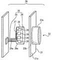
図3に示すように入力部20は、センサパネル21、凸状センサ部22、フィルム部材25、センサ素子26及び配線部27を備えている。 As shown in FIG. 3, the
センサパネル21は、樹脂により板状に形成され、入力部20における外側の意匠面21aを構成している。センサパネル21は、例えば車両のインストルメントパネルの前面に沿って設けられている。尚、図1に示すように、センサパネル21には、入力部20の他に、車両用空調装置1における内外気モードを切替える内外気スイッチ12a、吹き出しモードを切替える吹き出しモードスイッチ12b、及び風量を切替える風量スイッチ12c等が設けられている。さらに、センサパネル21には、上記各スイッチ12a〜12cによって設定された各モード状態、及び入力部20によって設定されたパラメータ2を表示する表示部3が設けられており、使用者は、当該表示部3の表示を見ながら各モードの切り替え及びパラメータ2の入力が可能となっている。 The
図3、4に示すように凸状センサ部22は、樹脂によりセンサパネル21と一体の有底円筒状に形成されている。凸状センサ部22は、センサパネル21の意匠面21aから突出することで、使用者の手指により接触可能に設けられている。凸状センサ部22において円筒面形を呈する外周面22aは、使用者の手指の接触を感知する感知面22aとして機能する。このような凸状センサ部22の外観は、従来から一般的に使用されている機械回転式のダイヤル部材と同様な外観となっている。 As shown in FIGS. 3 and 4, the
フィルム部材25は、可撓性を有する薄膜部材であり、例えばポリエチレンテレフタレートやポリイミド等の樹脂により形成されている。フィルム部材25は、リング状部28と、帯状部29とを有している。リング状部28は、凸状センサ部22の内周面22bに沿う円環状に形成され、当該凸状センサ部22内に同軸上に収容されている。帯状部29
は、リング状部28の周方向の一箇所から凸状センサ部22の底部とは反対側へ延出している。The
Is extended from one place in the circumferential direction of the ring-shaped
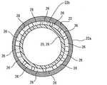
センサ素子26は、例えば金属乃至は導電性物質含有の印刷部材等により薄膜状に形成され、フィルム部材25のうちリング状部28の外周面28aに複数(本実施形態では、例えば14個)、接合されている。各センサ素子26は、外周側を囲む凸状センサ部22の感知面22aに沿って周方向に並ぶように、互いに等間隔に配置されている。各センサ素子26は、感知面22aに対して接触点60(図5の例示参照)を形成する使用者の手指との間で、凸状センサ部22を介してコンデンサを構成することで、当該手指との間の静電容量を表す信号を出力する。 The
ここで、感知面22aに対する使用者の接触点60(図5参照)の直近に位置するときに閾値以上の振幅の信号を出力するセンサ素子26を直近センサ素子26aと定義し、接触点60に対して当該直近センサ素子26aよりも離間して閾値未満の振幅の信号を出力するセンサ素子26を離間センサ素子26bと定義する。かかる定義の下、閾値以上の振幅の信号を出力する直近センサ素子26aの配置箇所は、感知面22aにおける使用者の接触点60を表すことになる。故に、少なくとも二つの直近センサ素子26aが周方向において互いに隣接する場合には、それら直近センサ素子26aから閾値以上の振幅をもって出力される信号に基づくことで、使用者の接触点60を感知面22aの周方向にて正確に識別可能できる。また、唯一つの直近センサ素子26aに対して離間センサ素子26bが周方向の両側に隣接する場合には、当該直近センサ素子26aから閾値以上の振幅をもって出力される信号に基づくことで、使用者の接触点60を感知面22aの周方向にて正確に識別できるのである。 Here, the
図3に示すように配線部27は、例えば金属や導電性物質含有の印刷部材等により線状に形成され、リング状部28の外周面28aから帯状部29の外周面29aに跨るようにしてフィルム部材25に接合されている。配線部27は、センサ素子26と同数だけ用意されて、各センサ素子26と対を成すように複数設けられている。各配線部27は、一端が対応するセンサ素子26に接続され、他端がメイン制御部30に接続されることで、当該対応センサ素子26からの出力信号をメイン制御部30へ伝送する。 As shown in FIG. 3, the
図1に示すメイン制御部30は、マイクロコンピュータを主体に構成され、入力部20の配線部27と車両用空調装置1の表示部3とに接続されている。メイン制御部30は、コンピュータプログラムを実行することにより、車両用空調装置1のパラメータ2を入力部20の入力値に応じて変更するための二つの機能ブロックを実現する。 The
一つ目の機能ブロックである接触検出ブロック31は、所定のサンプリング周期毎(例えば10mS毎)に、各配線部27を介して各センサ素子26の出力信号の取り込みを行う。さらに接触検出ブロック31は、取り込んだ各センサ素子26からの出力信号のうち、閾値以上の振幅を表す信号を識別することによって、感知面22aに対する接触の有無と、感知面22aの周方向における接触点60の位置とを検出する。 The contact detection block 31 that is the first functional block captures the output signal of each
二つ目の機能ブロックである変更制御ブロック32は、接触検出ブロック31により接触点60を複数検出すると、パラメータ2の変更又は維持を待機する待機状態となる。待機状態において、接触検出ブロック31により検出された複数の接触点60のうち少なくとも一つが感知面22aの周方向へスライド変化するときに、当該変化のパターンが所定の変更条件と一致する場合には、パラメータ2を変更する。ここで、本実施形態の変更制御ブロック32は、待機状態において唯一の接触点60が感知面22aの周方向にスライド変化する現象、並びに少なくとも二つの接触点60が感知面22aの周方向の同一方向にスライド変化する現象を、変更条件とする。また、一方で変更制御ブロック32は、待機状態において検出された複数の接触点60のうち少なくとも一つのスライド変化時に当該変化のパターンが所定の維持条件と一致する場合には、パラメータ2を維持する。ここで、本実施形態の変更制御ブロック32は、待機状態において少なくとも一つの接触点60が感知面22aの周方向の一方にスライド変化し、かつ少なくとも一つの接触点60が感知面22aの周方向の他方に前記スライド変化する現象を、維持条件とする。 When a plurality of contact points 60 are detected by the contact detection block 31, the change control block 32, which is the second function block, enters a standby state in which the
次に、メイン制御部30による入力装置100の制御フローについて、図6を参照しつつ説明する。 Next, a control flow of the
制御フローのS101では、接触検出ブロック31により、使用者が入力部20の感知面22aに接触したか否かを、各センサ素子26の出力信号に基づき判定する。S101において否定判定がなされている間は、S101が繰り返し実行され、S101において肯定判定がなされると、S102へ移行する。 In S <b> 101 of the control flow, the contact detection block 31 determines whether or not the user has touched the
S102では、接触検出ブロック31により検出される接触点60が複数点あるか否かを、変更制御ブロック32により判定し、S102において否定判定がなされている間は、S101へ戻り、S102において肯定判定がなされると、変更制御ブロック32は、待機状態となり、S103へ移行する。 In S102, it is determined by the change control block 32 whether or not there are a plurality of contact points 60 detected by the contact detection block 31, and while a negative determination is made in S102, the process returns to S101, and an affirmative determination is made in S102. When the change is made, the change control block 32 enters a standby state and proceeds to S103.
S103では、接触検出ブロック31により検出される複数の接触点60のうち少なくとも一点が感知面22aの周方向にスライド変化したか否かを、変更制御ブロック32により判定する。その結果、肯定判定がなされると、S104へ移行する。 In S103, the change control block 32 determines whether or not at least one of the plurality of contact points 60 detected by the contact detection block 31 has slid in the circumferential direction of the
S104では、S103にて確認された接触点60のスライド変化のパターンが変更条件及び維持条件のうちいずれと一致しているかを、変更制御ブロック32により判定する。その結果、変化パターンが変更条件と一致していると判定された場合には、S105へ移行する一方、変化パターンが維持条件と一致していると判定された場合にはS106へ移行する。 In S104, the change control block 32 determines which of the change condition and the maintenance condition the slide change pattern of the
ここで変更条件とは、各接触点60のスライド変化のパターンが以下の現象A1、A2のいずれかである場合をいう。
(A1)接触検出ブロック31により検出される複数の接触点60のうち、唯一の接触点60が周方向にスライド変化する。
(A2)接触検出ブロック31により検出される複数の接触点60のうち、少なくとも二つの接触点60が周方向の同一方向にスライド変化する。(図5(a)に一例を示す。)
このような変更条件に変化パターンが一致することで移行するS105では、変更制御ブロック32によりパラメータ2を変更する。このとき本実施形態では、一致した変更条件が現象A1である場合、唯一つの接触点60のスライド変化に応じて、パラメータ2が変更される。また、一致した変更条件が現象A2である場合には、スライド変化した少なくとも二つの接触点60のうち、いずれか一つの接触点60のスライド変化に応じて、パラメータ2が変更される。Here, the change condition refers to a case where the slide change pattern of each
(A1) Among the plurality of contact points 60 detected by the contact detection block 31, only one
(A2) At least two of the contact points 60 detected by the contact detection block 31 slide and change in the same circumferential direction. (An example is shown in FIG. 5 (a).)
In S105, where the change pattern matches the change condition, the
以上に対して維持条件とは、各接触点60のスライド変化のパターンが以下の現象A3である場合をいう。
(A3)接触検出ブロック31により検出される複数の接触点60のうち、少なくとも一つの接触点60が感知面22aの周方向の一方にスライド変化し、かつ少なくとも一つの接触点60が周方向の他方にスライド変化する。(図5(b)に一例を示す。)
このような維持条件に変化パターンが一致することで移行するS106では、変更制御ブロック32によりパラメータ2を維持する。また、S103において否定判定がなされた場合にもS106へ移行して、変更制御ブロック32によりパラメータ2を維持する。On the other hand, the maintenance condition refers to the case where the slide change pattern of each
(A3) Among the plurality of contact points 60 detected by the contact detection block 31, at least one
In S106, which shifts when the change pattern matches such a maintenance condition, the
(作用効果)
ここまで説明した第一実施形態の入力装置100による作用効果を、以下に詳細に説明する。(Function and effect)
The effects of the
第一実施形態において、感知面22aに対する使用者の接触点60が接触検出ブロック31により複数検出されたとき、変更制御ブロック32は待機状態となってパラメータ2を変更又は維持するために待機する。これにより、使用者が感知面22aの複数の接触点60により接触するという明らかにパラメータ2の変更又は維持を意図する場合にのみ待機状態となるので、使用者が意図せずに感知面22aに接触してしまった場合に変更制御ブロック32によりパラメータ2が誤って変更されることを抑制する。従って、誤ったパラメータ2変更を抑制するためのフェールセーフ性を高めることが、可能である。 In the first embodiment, when a plurality of contact points 60 of the user with respect to the
さらに、第一実施形態において、待機状態において接触点60が接触検出ブロック31により複数検出され、そのうち少なくとも一つが変化し、当該変化のパターンが所定の変更条件と一致する場合には、パラメータ2は変更制御ブロック32により変更される。これにより、使用者がパラメータ2の変更を意図する場合に生じると想定される変更条件に接触点60の変化パターンが一致した場合に限って、パラメータ2を変更できる。その結果、待機状態において使用者がパラメータ2の変更を行うためではなく、意図せずにその接触点60を変化させてしまったとしても、パラメータ2が誤って変更されるような事態は、抑制され得る。したがって、誤ったパラメータ2変更を抑制するためのフェールセーフ性をより高めることが、可能である。 Furthermore, in the first embodiment, when a plurality of contact points 60 are detected by the contact detection block 31 in the standby state, at least one of them changes, and the change pattern matches a predetermined change condition, the
また、第一実施形態において、待機状態における変更条件として唯一の接触点60が感知面22aの周方向にスライド変化する現象が規定されているため、例えば使用者が一本の指を動かした場合に限ってパラメータ2を変更することができる。したがって、フェールセーフ性を高めるために、誤ったパラメータ変更を確実に抑制することが可能となる。 Further, in the first embodiment, since the phenomenon that the
また、第一実施形態において、待機状態における変更条件として複数の接触点60が感知面22aの周方向の同一方向にスライド変化する現象が規定されているため、例えば使用者が複数の指を同一方向に動かした場合に限ってパラメータ2を変更することができる。したがって、フェールセーフ性を高めるために、誤ったパラメータ変更を確実に抑制することが可能となる。 Further, in the first embodiment, since the phenomenon that the plurality of contact points 60 slide and change in the same circumferential direction of the
加えて、第一実施形態において、感知面22aに対する使用者の接触点60が接触検出ブロック31により複数検出された後、待機状態においてそのうち少なくとも一つが変化し、当該変化のパターンが所定の維持条件と一致する場合に、パラメータ2は変更制御ブロック32により維持される。これにより、使用者がパラメータ2の変更を意図しない場合に生じると想定される維持条件に接触点60の変化パターンが一致した場合には、パラメータ2を変更せずに維持できる。その結果、使用者が意図せずに感知面22aに接触してその接触点60を変化させてしまったとしても、パラメータ2が誤って変更されるような事態は確実に抑制され得るので、フェールセーフ性を高めることが可能となる。 In addition, in the first embodiment, after a plurality of contact points 60 of the user with respect to the
さらに加えて、第一実施形態において、待機状態における維持条件として少なくとも一つずつの接触点60が周方向の相反方向へスライド変化する現象が規定されているため、例えば使用者が二本の指を感知面22aに沿って互いに近づけながら引き上げることで、意図しない接触点60のスライド変化を生じさせてしまった場合に、パラメータ2が変更されるのを抑制することができる。したがって、フェールセーフ性を高めるために、誤ったパラメータ変更を確実に抑制することが可能となる。 In addition, in the first embodiment, since a phenomenon in which at least one
さらに、第一実施形態では、感知面22aに沿って周方向に等間隔に並ぶ複数のセンサ素子26のうち、同感知面22aに対する使用者の接触点60の直近に位置する少なくとも二つの直近センサ素子26aが周方向において互いに隣接する場合、それら直近センサ素子26aからの出力信号は、当該接触点60を表すものとなる。故に、互いに隣接する直近センサ素子26aからの出力信号に基づくことで、パラメータ2の入力値を決める接触点60を感知面22aの周方向にて正確に検出できる。また、接触点60に対して直近センサ素子26aよりも離間した離間センサ素子26bが唯一の直近センサ素子26aの周方向両側に隣接する場合、当該直近センサ素子26aからの出力信号は、当該接触点60を表すものとなる。故に、唯一の直近センサ素子26aからの出力信号に基づくことで、パラメータ2の入力値を決める当該接触点60を感知面22aの周方向にて正確に検出できる。これによれば、一つもしくは複数の直近センサ素子26aからの出力信号に基づいて、感知面22aに対する使用者の接触点60を正確に検出することで、使用者が感知面22aに沿って周方向に複数点を接触した場合におけるパラメータ2の正確な入力という点で貢献することが可能である。 Furthermore, in the first embodiment, among the plurality of
また、第一実施形態では、凸状センサ部22と共に車両に搭載される表示部3の表示パラメータ2として、車両用空調装置1の作動状態を定める車両パラメータ2が制御対象となる。これにより使用者は、振動の発生しやすい車両においても、筒面形感知面22aに対する接触点60を所定のパターンで変化させることで、表示部3を見ながら車両パラメータ2を確実に入力することが可能となる。 Moreover, in 1st embodiment, the
(第二実施形態)
図7に示すように、本発明の第二実施形態は第一実施形態の変形例である。第二実施形態において変更制御ブロック32は、待機状態においてスライド変化した接触点60が少なくとも二つある場合には、それら接触点60の周方向における変化量Qの平均値に応じて、パラメータ2を変更する。例えば本実施形態では、平均値が大きいほど、パラメータ2の時間変化率を大きく設定し、平均値が小さいほど、パラメータ2の時間変化率を小さく設定する。(Second embodiment)
As shown in FIG. 7, the second embodiment of the present invention is a modification of the first embodiment. In the second embodiment, when there are at least two
ここで、平均値を算出するのに必要な一接触点60に関する変化量Qの導出方法を、具体的に説明する。図8では、複数のセンサ素子26のそれぞれをS1〜Snとする。各S1〜Snは、感知面22aの周方向に沿ってセンサ番号が大きくなっていくように並んでいる。接触検出ブロック31は、感知面22aに対する接触開始時に静電容量が閾値を超えたセンサ素子26の位置を開始位置Psとして検出する(図8の例では、チェックボックスが黒く塗りつぶされたS3)。また、感知面22aに対する接触点のスライド変化が止まった停止時に接触検出ブロック31は、静電容量が閾値を超えたセンサ素子26の位置を終了位置Pfとして検出する(図8の例では、チェックボックスが黒く塗りつぶされたS4)。そして、変更制御ブロック32は、こうして検出された開始位置Psと終了位置Pfとの差を変化量Q(図8の例では、1)として算出する。 Here, a method for deriving the amount of change Q relating to one
このような第二実施形態では、図7に示す制御フローのS104において変更条件が変化パターンと一致していると判定されると、S2104aへ移行する。 In such a second embodiment, when it is determined in S104 of the control flow shown in FIG. 7 that the change condition matches the change pattern, the process proceeds to S2104a.
S2104aでは、変更制御ブロック32により、スライド変化した接触点60が二点以上あるか否かを判定し、S2104aで肯定判定がなされると、S2104bへ移行する一方、S2104aで否定判定がなされると、S2104dへ移行する。 In S2104a, it is determined by the change control block 32 whether or not there are two or more contact points 60 that have slid, and if an affirmative determination is made in S2104a, the process proceeds to S2104b, whereas a negative determination is made in S2104a. , The process proceeds to S2104d.
具体的に、スライド変化した接触点60が二点以上の場合に移行するS2104bでは、変更制御ブロック32により、それら接触点60毎に、開始位置Psと終了位置Pfの差から変化量Qをそれぞれ読み込む。次にS2104cでは、変更制御ブロック32により、S2104bにて読み込まれた変化量Qの平均値を算出し、さらに続くS2105aでは、変更制御ブロック32により、当該算出平均値に応じてパラメータ2を変更する。 Specifically, in S2104b, which is shifted when there are two or more sliding contact points 60, the change control block 32 determines the change amount Q from the difference between the start position Ps and the end position Pf for each
一方、スライド変化した接触点60が唯一の場合に移行するS2104dでは、変更制御ブロック32により、当該唯一の接触点60の変化量Qを開始位置Psと終了位置Pfの差から読み込む。次にS2105bでは、変更制御ブロック32により、S2104dにて読み込まれた接触点60の変化量Qに応じて、パラメータ2を変更する。 On the other hand, in S2104d, when the sliding
以上、説明した第二実施形態では、パラメータ2は、待機状態においてスライド変化した複数の接触点60の周方向における変化量Qの平均値に応じて、変更制御ブロック32により変更される。これによれば、複数の接触点60の変化量60のばらつきが平均されるので、例えば使用者の意図しない接触点60の急変がパラメータ2の変更に影響しにくくなる。その結果として、フェールセーフ性を高めた入力装置100を提供できるのである。 As described above, in the second embodiment described above, the
(他の実施形態)
以上、本発明の複数の実施形態について説明したが、本発明は、それらの実施形態に限定して解釈されるものではなく、本発明の要旨を逸脱しない範囲内において種々の実施形態及び組み合わせに適用することができる。(Other embodiments)
Although a plurality of embodiments of the present invention have been described above, the present invention is not construed as being limited to these embodiments, and various embodiments and combinations can be made without departing from the scope of the present invention. Can be applied.
具体的には、第一実施形態及び第二実施形態において、凸状センサ部22は、有底円筒状に形成されているが、これに限定されることなく、例えば底面が楕円、あるいは長方形等の多角形に形成される凸状センサ部22を採用しても良い。ここで一般的な回転式のスイッチでは、文字通り回転させる必要があったことから、ほぼ円筒状とすることが常識であったが、凸状センサ部22自体は実質的に回転しないことから、例えば底面形状を上記のような楕円とすることで、従来にない斬新なデザインを持つ入力装置100とすることができる。 Specifically, in the first embodiment and the second embodiment, the
第一実施形態及び第二実施形態においてセンサ素子26には、静電容量式のセンサを用いているが、これに限らず、接触時の押圧力をもって一信号を発生する感圧式のセンサ素子を用いても良い。また、第一実施形態及び第二実施形態においてセンサ素子26は、フィルム部材25のリング状部28の外側の面に接合されているが、リング状部28の内側の面に接合させても良い。さらに、第一実施形態及び第二実施形態においてフィルム部材25を廃止して、センサ素子26を直接、凸状センサ部22の感知面22aの内周面22bに接合させても良い。 In the first embodiment and the second embodiment, a capacitive sensor is used as the
第二実施形態において変更制御ブロック32は、スライド変化する接触点60が少なくとも二つ(二点以上)存在する場合、変化量Qの平均値に応じてパラメータ2を変更しているが、複数の接触点60の変化量Qの最大値、最小値、及びその他の値に応じてパラメータ2を変更しても良い。また、第一実施形態及び第二実施形態において、変更条件(A2)は、全ての接触点60が周方向の同一方向へ変化する現象に設定しても良い。 In the second embodiment, the change control block 32 changes the
第一実施形態及び第二実施形態の入力装置100については、車両用空調装置1の設定温度を入力するものとしたが、他にも、空調空気の車室内への吹出し量(送風量)を入力するもの、吹出しモード(フェイスモード、フットモード等)を入力するもの等としても良い。あるいは、車両用オーディオにおけるボリューム、あるいはラジオ選曲等を入力するものとしても良い。さらに車両に限らず、家庭用の各種機器の入力装置100に適用することができる。 About the
2 パラメータ、3 表示部、20 入力部、21 センサパネル、22 凸状センサ部、22a 感知面、26 センサ素子、26a 直近センサ素子、26b 離間センサ素子、30 メイン制御部、31 接触検出ブロック(接触検出手段)、32 変更制御ブロック(制御手段)、60 接触点、100 入力装置2 parameters, 3 display section, 20 input section, 21 sensor panel, 22 convex sensor section, 22a sensing surface, 26 sensor element, 26a nearest sensor element, 26b separation sensor element, 30 main control section, 31 contact detection block (contact Detection means), 32 change control block (control means), 60 contact points, 100 input device
Claims (7)
Translated fromJapanese使用者により接触可能に突出して感知面を形成する凸状センサ部と、
前記感知面に対する前記使用者の接触点を検出する接触検出手段と、
前記接触検出手段により検出された前記接触点に基づいて前記パラメータを制御する制御手段と、を備え、
前記制御手段は、前記接触検出手段により複数の前記接触点が検出されたとき、前記パラメータを変更又は維持するために待機する待機状態となり、
前記制御手段は、前記待機状態において前記接触検出手段により検出された複数の前記接触点のうち少なくとも一つが変化するとき、当該変化のパターンが所定の維持条件と一致する場合に、前記パラメータを維持し、
前記制御手段は、前記待機状態において前記接触検出手段により検出された複数の前記接触点のうち、少なくとも一つの前記接触点が前記感知面の周方向の一方にスライド変化し、かつ少なくとも一つの前記接触点が前記感知面の周方向の他方にスライド変化する現象を、前記維持条件とすることを特徴とする入力装置。An input device for inputting a parameter for determining an operating state of a predetermined device,
A convex sensor part that protrudes so as to be contactable by a user and forms a sensing surface;
Contact detection means for detecting a contact point of the user with the sensing surface;
Control means for controlling the parameter based on the contact point detected by the contact detection means,
Wherein, when a plurality of the contact points is detected by the contact detecting means,Ri Do a standby state to wait for modifying or maintaining the saidparameters,
The control means maintains the parameter when at least one of the contact points detected by the contact detection means changes in the standby state, and the change pattern matches a predetermined maintenance condition. And
The control unit is configured to slide at least one of the plurality of contact points detected by the contact detection unit in the standby state in one of the circumferential directions of the sensing surface, and at least one of the contact points. The input devicecharacterized in that the maintenance condition is a phenomenon in which the contact point slides to the other circumferential direction of the sensing surface .
前記接触点の直近に位置する前記センサ素子を直近センサ素子とし、前記接触点に対して当該直近センサ素子よりも離間した前記センサ素子を離間センサ素子とする定義の下、前記接触検出手段は、
少なくとも二つの前記直近センサ素子が前記周方向において互いに隣接する場合、それら直近センサ素子からの出力信号に基づいて前記接触点を検出し、
唯一の前記直近センサ素子に対して前記離間センサ素子が前記周方向の両側に隣接する場合、当該直近センサ素子からの出力信号に基づいて前記接触点を検出することを特徴とする請求項1〜5のいずれか一項に記載の入力装置。The convex sensor portion has a plurality of sensor elements arranged at equal intervals in the circumferential direction along the sensing surface,
Under the definition that the sensor element located in the immediate vicinity of the contact point is a nearest sensor element, and the sensor element that is separated from the nearest sensor element with respect to the contact point is a separated sensor element, the contact detection means is:
When at least two of the nearest sensor elements are adjacent to each other in the circumferential direction, the contact point is detected based on an output signal from the nearest sensor elements,
The contact point is detected based on an output signal from the nearest sensor element when the separation sensor element is adjacent to both sides in the circumferential direction with respect to the only nearest sensor element. The input device according to claim 5 .
Priority Applications (1)
| Application Number | Priority Date | Filing Date | Title |
|---|---|---|---|
| JP2012067996AJP5817613B2 (en) | 2012-03-23 | 2012-03-23 | Input device |
Applications Claiming Priority (1)
| Application Number | Priority Date | Filing Date | Title |
|---|---|---|---|
| JP2012067996AJP5817613B2 (en) | 2012-03-23 | 2012-03-23 | Input device |
Publications (2)
| Publication Number | Publication Date |
|---|---|
| JP2013200664A JP2013200664A (en) | 2013-10-03 |
| JP5817613B2true JP5817613B2 (en) | 2015-11-18 |
Family
ID=49520878
Family Applications (1)
| Application Number | Title | Priority Date | Filing Date |
|---|---|---|---|
| JP2012067996AExpired - Fee RelatedJP5817613B2 (en) | 2012-03-23 | 2012-03-23 | Input device |
Country Status (1)
| Country | Link |
|---|---|
| JP (1) | JP5817613B2 (en) |
Families Citing this family (3)
| Publication number | Priority date | Publication date | Assignee | Title |
|---|---|---|---|---|
| WO2015155968A1 (en)* | 2014-04-10 | 2015-10-15 | パナソニックIpマネジメント株式会社 | Input device |
| JP2016025403A (en)* | 2014-07-17 | 2016-02-08 | カシオ計算機株式会社 | Electrostatic switch pad curve surface mounting structure and electronic apparatus |
| KR101902434B1 (en) | 2014-11-13 | 2018-10-01 | 현대자동차주식회사 | Control apparatus using touch and vehicle comprising the same |
Family Cites Families (11)
| Publication number | Priority date | Publication date | Assignee | Title |
|---|---|---|---|---|
| JP2003337649A (en)* | 2002-05-20 | 2003-11-28 | Sony Corp | Input method and input device |
| KR101128572B1 (en)* | 2004-07-30 | 2012-04-23 | 애플 인크. | Gestures for touch sensitive input devices |
| CN102841713A (en)* | 2005-09-15 | 2012-12-26 | 苹果公司 | System and method for processing raw data of track pad device |
| JP4693051B2 (en)* | 2006-01-27 | 2011-06-01 | アルパイン株式会社 | Signal input device |
| JP2008216991A (en)* | 2008-01-29 | 2008-09-18 | Fujitsu Ten Ltd | Display device |
| EP2166669A1 (en)* | 2008-09-17 | 2010-03-24 | Electrolux Home Products Corporation N.V. | Cooktop assembly comprising flush-mounted cooktop panel |
| JP5108747B2 (en)* | 2008-12-26 | 2012-12-26 | 富士フイルム株式会社 | Information display apparatus, method and program |
| JP5347589B2 (en)* | 2009-03-10 | 2013-11-20 | 株式会社オートネットワーク技術研究所 | Operating device |
| KR101674713B1 (en)* | 2009-09-29 | 2016-11-09 | 레노보 이노베이션스 리미티드 (홍콩) | Display device, control method and recording medium |
| JP2011201497A (en)* | 2010-03-26 | 2011-10-13 | Aisin Aw Co Ltd | Operation accepting device, method and program |
| JP5536019B2 (en)* | 2011-11-30 | 2014-07-02 | 京セラ株式会社 | Portable electronic device and control method thereof |
- 2012
- 2012-03-23JPJP2012067996Apatent/JP5817613B2/ennot_activeExpired - Fee Related
Also Published As
| Publication number | Publication date |
|---|---|
| JP2013200664A (en) | 2013-10-03 |
Similar Documents
| Publication | Publication Date | Title |
|---|---|---|
| US20180059815A1 (en) | Capacitive rotary encoder | |
| US9691315B2 (en) | Touch-type input device | |
| US10108293B2 (en) | Touch-type input device | |
| EP2960756A1 (en) | Touch-type input device | |
| US20170075482A1 (en) | Touch-type input device | |
| EP3117293B1 (en) | Correcting a cursor position for an operating device for a vehicle | |
| US10166868B2 (en) | Vehicle-mounted equipment operation support system | |
| EP2918440A1 (en) | Vehicle operation apparatus | |
| US10747367B2 (en) | OBDII failure diagnostics techniques for knobs and buttons | |
| JP2012003404A (en) | Information display device | |
| JP5817613B2 (en) | Input device | |
| CN113246729A (en) | Operating device | |
| JP6070363B2 (en) | Input device | |
| WO2015170448A1 (en) | Operation device | |
| WO2015052887A1 (en) | Capacitive switch | |
| JP5084872B2 (en) | Touch switch | |
| JP2009217956A (en) | Electrostatic input device and electronic equipment | |
| JP4700632B2 (en) | Multi-directional operation device | |
| JP5794183B2 (en) | Input device | |
| JP5919996B2 (en) | Input device and operation device | |
| CN113168269B (en) | Input device having a touch screen or touch pad and an input component having a slide-fit haptic therein | |
| JP2014044586A (en) | Operation input device | |
| JP2017157075A (en) | Operation detection device | |
| JP5909085B2 (en) | Touch sensor | |
| JP2016139234A (en) | Input control device |
Legal Events
| Date | Code | Title | Description |
|---|---|---|---|
| A621 | Written request for application examination | Free format text:JAPANESE INTERMEDIATE CODE: A621 Effective date:20140515 | |
| A977 | Report on retrieval | Free format text:JAPANESE INTERMEDIATE CODE: A971007 Effective date:20150225 | |
| A131 | Notification of reasons for refusal | Free format text:JAPANESE INTERMEDIATE CODE: A131 Effective date:20150324 | |
| A521 | Written amendment | Free format text:JAPANESE INTERMEDIATE CODE: A523 Effective date:20150521 | |
| TRDD | Decision of grant or rejection written | ||
| A01 | Written decision to grant a patent or to grant a registration (utility model) | Free format text:JAPANESE INTERMEDIATE CODE: A01 Effective date:20150901 | |
| A61 | First payment of annual fees (during grant procedure) | Free format text:JAPANESE INTERMEDIATE CODE: A61 Effective date:20150914 | |
| R151 | Written notification of patent or utility model registration | Ref document number:5817613 Country of ref document:JP Free format text:JAPANESE INTERMEDIATE CODE: R151 | |
| R250 | Receipt of annual fees | Free format text:JAPANESE INTERMEDIATE CODE: R250 | |
| R250 | Receipt of annual fees | Free format text:JAPANESE INTERMEDIATE CODE: R250 | |
| LAPS | Cancellation because of no payment of annual fees |