JP5815510B2 - Method and apparatus for performing knee arthroplasty - Google Patents
Method and apparatus for performing knee arthroplastyDownload PDFInfo
- Publication number
- JP5815510B2 JP5815510B2JP2012513307AJP2012513307AJP5815510B2JP 5815510 B2JP5815510 B2JP 5815510B2JP 2012513307 AJP2012513307 AJP 2012513307AJP 2012513307 AJP2012513307 AJP 2012513307AJP 5815510 B2JP5815510 B2JP 5815510B2
- Authority
- JP
- Japan
- Prior art keywords
- tibial
- resection
- trial
- proximal tibia
- medial
- Prior art date
- Legal status (The legal status is an assumption and is not a legal conclusion. Google has not performed a legal analysis and makes no representation as to the accuracy of the status listed.)
- Expired - Fee Related
Links
- 238000011882arthroplastyMethods0.000titleclaimsdescription39
- 238000000034methodMethods0.000titledescription193
- 210000003127kneeAnatomy0.000titledescription34
- 238000002271resectionMethods0.000claimsdescription471
- 210000002303tibiaAnatomy0.000claimsdescription444
- 210000000689upper legAnatomy0.000claimsdescription173
- 239000007943implantSubstances0.000claimsdescription124
- 210000000629knee jointAnatomy0.000claimsdescription32
- 230000003362replicative effectEffects0.000claimsdescription5
- 210000000988bone and boneAnatomy0.000description80
- 238000005553drillingMethods0.000description64
- 238000005520cutting processMethods0.000description58
- 238000002679ablationMethods0.000description55
- 241001422033ThestylusSpecies0.000description51
- 238000001356surgical procedureMethods0.000description35
- 241001227561ValgusSpecies0.000description34
- 230000007935neutral effectEffects0.000description33
- 241000469816VarusSpecies0.000description29
- 230000007246mechanismEffects0.000description25
- 230000006870functionEffects0.000description20
- 210000003041ligamentAnatomy0.000description19
- 210000001264anterior cruciate ligamentAnatomy0.000description18
- 238000003780insertionMethods0.000description16
- 230000037431insertionEffects0.000description16
- 238000013519translationMethods0.000description15
- 230000008878couplingEffects0.000description13
- 238000010168coupling processMethods0.000description13
- 238000005859coupling reactionMethods0.000description13
- 210000002967posterior cruciate ligamentAnatomy0.000description13
- 230000001054cortical effectEffects0.000description10
- 238000011156evaluationMethods0.000description10
- 230000002829reductive effectEffects0.000description8
- 230000008901benefitEffects0.000description7
- 208000006111contractureDiseases0.000description7
- 238000010586diagramMethods0.000description7
- 230000000670limiting effectEffects0.000description7
- 230000009467reductionEffects0.000description7
- 125000006850spacer groupChemical group0.000description7
- 238000011883total knee arthroplastyMethods0.000description7
- 238000013150knee replacementMethods0.000description6
- 210000004872soft tissueAnatomy0.000description5
- 210000003484anatomyAnatomy0.000description4
- 210000002414legAnatomy0.000description4
- 210000001699lower legAnatomy0.000description4
- 238000002360preparation methodMethods0.000description4
- 230000006641stabilisationEffects0.000description4
- 238000011105stabilizationMethods0.000description4
- 241000879887Cyrtopleura costataSpecies0.000description3
- 206010062575Muscle contractureDiseases0.000description3
- 238000013459approachMethods0.000description3
- 230000008859changeEffects0.000description3
- 238000007796conventional methodMethods0.000description3
- 238000013461designMethods0.000description3
- 210000003811fingerAnatomy0.000description3
- 238000002513implantationMethods0.000description3
- 230000003993interactionEffects0.000description3
- 238000004519manufacturing processMethods0.000description3
- 238000005259measurementMethods0.000description3
- 238000004321preservationMethods0.000description3
- 238000000429assemblyMethods0.000description2
- 230000000712assemblyEffects0.000description2
- 230000002146bilateral effectEffects0.000description2
- 210000000845cartilageAnatomy0.000description2
- 210000004439collateral ligamentAnatomy0.000description2
- 230000000694effectsEffects0.000description2
- 239000003550markerSubstances0.000description2
- 230000035515penetrationEffects0.000description2
- 238000012360testing methodMethods0.000description2
- 230000000007visual effectEffects0.000description2
- 208000037408Device failureDiseases0.000description1
- 230000005856abnormalityEffects0.000description1
- 230000002411adverseEffects0.000description1
- 210000003423ankleAnatomy0.000description1
- 210000000544articulatio talocruralisAnatomy0.000description1
- 238000005452bendingMethods0.000description1
- 230000015572biosynthetic processEffects0.000description1
- 239000004568cementSubstances0.000description1
- 239000011248coating agentSubstances0.000description1
- 238000000576coating methodMethods0.000description1
- 230000006835compressionEffects0.000description1
- 238000007906compressionMethods0.000description1
- 238000001804debridementMethods0.000description1
- 230000007547defectEffects0.000description1
- 238000005516engineering processMethods0.000description1
- 239000006260foamSubstances0.000description1
- 230000000977initiatory effectEffects0.000description1
- 230000002452interceptive effectEffects0.000description1
- 238000010329laser etchingMethods0.000description1
- 238000012986modificationMethods0.000description1
- 230000004048modificationEffects0.000description1
- 210000000426patellar ligamentAnatomy0.000description1
- 229920001610polycaprolactonePolymers0.000description1
- 230000008569processEffects0.000description1
- 230000002035prolonged effectEffects0.000description1
- 230000001902propagating effectEffects0.000description1
- 230000009023proprioceptive sensationEffects0.000description1
- 238000011867re-evaluationMethods0.000description1
- 230000000717retained effectEffects0.000description1
- 230000035807sensationEffects0.000description1
- 230000035945sensitivityEffects0.000description1
- 238000010008shearingMethods0.000description1
- 238000004513sizingMethods0.000description1
- 230000000087stabilizing effectEffects0.000description1
- 238000003860storageMethods0.000description1
- 239000000758substrateSubstances0.000description1
- 210000002435tendonAnatomy0.000description1
- 210000003813thumbAnatomy0.000description1
- 238000012800visualizationMethods0.000description1
Images


Classifications
- A—HUMAN NECESSITIES
- A61—MEDICAL OR VETERINARY SCIENCE; HYGIENE
- A61B—DIAGNOSIS; SURGERY; IDENTIFICATION
- A61B17/00—Surgical instruments, devices or methods
- A61B17/14—Surgical saws
- A61B17/15—Guides therefor
- A61B17/154—Guides therefor for preparing bone for knee prosthesis
- A61B17/155—Cutting femur
- A—HUMAN NECESSITIES
- A61—MEDICAL OR VETERINARY SCIENCE; HYGIENE
- A61B—DIAGNOSIS; SURGERY; IDENTIFICATION
- A61B17/00—Surgical instruments, devices or methods
- A61B17/14—Surgical saws
- A61B17/15—Guides therefor
- A61B17/154—Guides therefor for preparing bone for knee prosthesis
- A61B17/157—Cutting tibia
- A—HUMAN NECESSITIES
- A61—MEDICAL OR VETERINARY SCIENCE; HYGIENE
- A61B—DIAGNOSIS; SURGERY; IDENTIFICATION
- A61B17/00—Surgical instruments, devices or methods
- A61B17/16—Instruments for performing osteoclasis; Drills or chisels for bones; Trepans
- A—HUMAN NECESSITIES
- A61—MEDICAL OR VETERINARY SCIENCE; HYGIENE
- A61B—DIAGNOSIS; SURGERY; IDENTIFICATION
- A61B17/00—Surgical instruments, devices or methods
- A61B17/16—Instruments for performing osteoclasis; Drills or chisels for bones; Trepans
- A61B17/17—Guides or aligning means for drills, mills, pins or wires
- A61B17/1739—Guides or aligning means for drills, mills, pins or wires specially adapted for particular parts of the body
- A61B17/1764—Guides or aligning means for drills, mills, pins or wires specially adapted for particular parts of the body for the knee
- A—HUMAN NECESSITIES
- A61—MEDICAL OR VETERINARY SCIENCE; HYGIENE
- A61F—FILTERS IMPLANTABLE INTO BLOOD VESSELS; PROSTHESES; DEVICES PROVIDING PATENCY TO, OR PREVENTING COLLAPSING OF, TUBULAR STRUCTURES OF THE BODY, e.g. STENTS; ORTHOPAEDIC, NURSING OR CONTRACEPTIVE DEVICES; FOMENTATION; TREATMENT OR PROTECTION OF EYES OR EARS; BANDAGES, DRESSINGS OR ABSORBENT PADS; FIRST-AID KITS
- A61F2/00—Filters implantable into blood vessels; Prostheses, i.e. artificial substitutes or replacements for parts of the body; Appliances for connecting them with the body; Devices providing patency to, or preventing collapsing of, tubular structures of the body, e.g. stents
- A61F2/02—Prostheses implantable into the body
- A61F2/30—Joints
- A61F2/46—Special tools for implanting artificial joints
- A61F2/4684—Trial or dummy prostheses
- A—HUMAN NECESSITIES
- A61—MEDICAL OR VETERINARY SCIENCE; HYGIENE
- A61F—FILTERS IMPLANTABLE INTO BLOOD VESSELS; PROSTHESES; DEVICES PROVIDING PATENCY TO, OR PREVENTING COLLAPSING OF, TUBULAR STRUCTURES OF THE BODY, e.g. STENTS; ORTHOPAEDIC, NURSING OR CONTRACEPTIVE DEVICES; FOMENTATION; TREATMENT OR PROTECTION OF EYES OR EARS; BANDAGES, DRESSINGS OR ABSORBENT PADS; FIRST-AID KITS
- A61F2/00—Filters implantable into blood vessels; Prostheses, i.e. artificial substitutes or replacements for parts of the body; Appliances for connecting them with the body; Devices providing patency to, or preventing collapsing of, tubular structures of the body, e.g. stents
- A61F2/02—Prostheses implantable into the body
- A61F2/30—Joints
- A61F2/38—Joints for elbows or knees
- A61F2/3859—Femoral components
- A—HUMAN NECESSITIES
- A61—MEDICAL OR VETERINARY SCIENCE; HYGIENE
- A61F—FILTERS IMPLANTABLE INTO BLOOD VESSELS; PROSTHESES; DEVICES PROVIDING PATENCY TO, OR PREVENTING COLLAPSING OF, TUBULAR STRUCTURES OF THE BODY, e.g. STENTS; ORTHOPAEDIC, NURSING OR CONTRACEPTIVE DEVICES; FOMENTATION; TREATMENT OR PROTECTION OF EYES OR EARS; BANDAGES, DRESSINGS OR ABSORBENT PADS; FIRST-AID KITS
- A61F2/00—Filters implantable into blood vessels; Prostheses, i.e. artificial substitutes or replacements for parts of the body; Appliances for connecting them with the body; Devices providing patency to, or preventing collapsing of, tubular structures of the body, e.g. stents
- A61F2/02—Prostheses implantable into the body
- A61F2/30—Joints
- A61F2/38—Joints for elbows or knees
- A61F2/389—Tibial components
Landscapes
- Health & Medical Sciences (AREA)
- Life Sciences & Earth Sciences (AREA)
- Surgery (AREA)
- Orthopedic Medicine & Surgery (AREA)
- General Health & Medical Sciences (AREA)
- Veterinary Medicine (AREA)
- Oral & Maxillofacial Surgery (AREA)
- Engineering & Computer Science (AREA)
- Biomedical Technology (AREA)
- Heart & Thoracic Surgery (AREA)
- Public Health (AREA)
- Animal Behavior & Ethology (AREA)
- Transplantation (AREA)
- Dentistry (AREA)
- Nuclear Medicine, Radiotherapy & Molecular Imaging (AREA)
- Medical Informatics (AREA)
- Molecular Biology (AREA)
- Physical Education & Sports Medicine (AREA)
- Vascular Medicine (AREA)
- Cardiology (AREA)
- Prostheses (AREA)
- Surgical Instruments (AREA)
Description
Translated fromJapanese[関連出願の相互参照]
本出願は2009年5月29日に出願された“Methods and Apparatus for performing Bicruciate Retaining Arthroplasty”という名称の米国仮特許出願第61/182,435号、及び2010年1月29日に出願された“Bi-Cruciate Retaining Tibial Implant”という名称の米国仮特許出願第61/299,835号に基づく優先権を主張し、その両方の全体的な内容を参照によって援用する。[Cross-reference of related applications]
This application is filed on May 29, 2009, US Provisional Patent Application No. 61 / 182,435 entitled “Methods and Apparatus for performing Bicruciate Retaining Arthroplasty” and filed on January 29, 2010. Claims priority under US Provisional Patent Application No. 61 / 299,835, entitled “Bi-Cruciate Retaining Tibial Implant”, the entire contents of both being incorporated by reference.
人工膝関節全置換術は多くの場合、前十字靭帯(ACL)及び後十字靭帯(PCL)を犠牲にする必要がある場合が多い。従って、人工膝関節は多くの場合、ACL及びPCLと同じ又は同様の機能を提供しようと試みる構造及び機構を含む。しかし、これらの従来の人工膝関節は、自然の靭帯がすべての患者にもたらす正常な固有受容感覚、運動、及び生体力学的機能を完全に復元することはない、と考える者もいる。過去には、前後十字靭帯温存型膝置換術が使用されていたが、不十分なインプラント設計、機器、及び/又は埋め込み技術に関連する可能性が高い、膝の硬直及びインプラントの失敗という問題と関連付けられてきた。そのため、場合によっては、膝関節置換術が必要な若年の活動的な患者には、膝置換術後に自然の感覚、及び正常な生体力学的機能及び動作を維持するように、機能する十字靭帯を保存することが望ましい。また、多くの膝手術(限定はされないが、特に前後十字靭帯温存手術)では、理想的とは言えない方法及び装置が使用されていることが多いため、場合によっては、前後十字靭帯温存型インプラント(すなわち、ACL及びPCL保存)ならびに他のタイプの膝インプラントのために大腿骨及び脛骨を準備するための、より効率的で正確な方法及び装置も必要とされている。 Total knee arthroplasty often requires sacrificing the anterior cruciate ligament (ACL) and the posterior cruciate ligament (PCL). Thus, knee prostheses often include structures and mechanisms that attempt to provide the same or similar functions as ACLs and PCLs. However, some believe that these conventional knee prostheses do not fully restore the normal proprioceptive sensation, movement, and biomechanical function that natural ligaments bring to all patients. In the past, anteroposterior cruciate ligament-sparing knee replacement was used, but the problems of knee stiffness and implant failure are likely to be related to poor implant design, equipment, and / or implantation techniques. Have been associated. Thus, in some cases, young active patients who require knee replacement surgery may function to maintain natural sensation and normal biomechanical function and operation after knee replacement surgery. It is desirable to preserve. Also, many knee surgeries (but not limited to, especially anteroposterior cruciate ligament-sparing surgery) often use less than ideal methods and devices, so in some cases, anteroposterior cruciate ligament-sparing implants There is also a need for more efficient and accurate methods and devices for preparing femurs and tibias for (ie, ACL and PCL storage) and other types of knee implants.
本明細書では、前後十字靭帯温存型関節形成術などの人工膝関節置換術(TKA)に有用な方法及び装置を含む、人工膝関節形成術を実施するための方法及び装置を説明する。 Described herein are methods and apparatus for performing total knee arthroplasty, including methods and apparatus useful for total knee arthroplasty (TKA), such as anterior-posterior cruciate ligament-sparing arthroplasty.
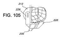
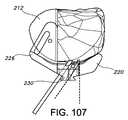
幾つかの実施形態では、膝関節の関節形成術のための手術用キットが提供され、手術用キットは大腿骨遠位部の大腿骨遠位側切除部を評価するための少なくとも1つの大腿骨遠位部トライアルを含み、大腿骨遠位部トライアルは、大腿骨遠位側切除部と接触するための最上部の上側平坦面;及び脛骨近位部の非切除面と接触するための少なくとも1つの顆部の表面を画成する下側湾曲面を含む。幾つかの実施形態では、下側湾曲面は、脛骨近位部の非切除面と接触するための内側及び外側顆部の表面を画成する。幾つかの実施形態では、大腿骨遠位部トライアルは、大腿骨遠位部トライアルの、大腿骨遠位部に対する内旋/外旋、前側/後側位置、内側/外側位置、又はサイズを測定するためのゲージである。幾つかの実施形態では、大腿骨遠位部トライアルは、大腿骨インプラントの、大腿骨遠位部に対する予想される位置及び向きを示すように、大腿骨遠位部トライアル上に置かれた1つ又は複数の基準を含む。幾つかの実施形態では、基準は、大腿骨遠位部トライアルの、大腿骨遠位側切除部の後側内側及び後側外側縁部に対する位置を示すように置かれている。幾つかの実施形態では、大腿骨遠位部トライアルの、大腿骨遠位側切除部の後側内側及び後側外側縁部に対する位置を示すための1つ又は複数の基準は、大腿骨遠位部トライアルの下側湾曲面の後縁部を含む。幾つかの実施形態では、大腿骨遠位部トライアルは、大腿骨遠位部トライアルの、大腿骨遠位側切除部の中心前側V字点に対する位置を示すための1つ又は複数の基準を含む。幾つかの実施形態では、大腿骨遠位部トライアルの、大腿骨遠位側切除部の中心前側V字点に対する位置を示すための1つ又は複数の基準は、大腿骨遠位部トライアルを通って延びる1つ又は複数の窓部を含む。幾つかの実施形態では、大腿骨遠位部トライアルは、前後十字靭帯温存型大腿骨遠位部トライアルを含む。幾つかの実施形態では、大腿骨遠位部トライアルは、実質的にU字形であり、脛骨近位部の脛骨隆起部の少なくとも一部分を受けるための内側及び外側顆部表面の間の間隙を画成する。幾つかの実施形態では、大腿骨遠位部トライアルは、前後十字靭帯温存型大腿骨インプラントの下側部分の形状、厚さ、及びサイズの少なくとも1つを実質的に複製する。幾つかの実施形態では、大腿骨遠位部トライアルは、大腿骨遠位部トライアルのサイズが異なる大腿骨遠位部トライアルのセットの一部である。幾つかの実施形態では、様々なサイズの大腿骨遠位部トライアルは、様々なサイズの大腿骨インプラントの遠位側部分を実質的に複製する。幾つかの実施形態では、大腿骨遠位部トライアルはモジュール式である。幾つかの実施形態では、手術用キットは、大腿骨遠位部トライアルの厚さを変えるための複数のシムを含む。幾つかの実施形態では、手術用キットは、大腿骨遠位部トライアルの外側顆部部分の厚さを変えるための複数のシムを含む。幾つかの実施形態では、手術用キットは、内反/外反角度及び屈曲/伸展角度の少なくとも1つを変えるための複数のシムを含む。幾つかの実施形態では、大腿骨遠位部トライアルは、様々な厚さの大腿骨遠位部トライアルのセットの一部である。幾つかの実施形態では、大腿骨遠位部トライアルは、様々な内反/外反角度又は様々な屈曲/伸展角度を有する大腿骨遠位部トライアルのセットの一部である。幾つかの実施形態では、手術用キットはまた、脛骨近位部に固定するためのアラインメントブロックを含み、アラインメントブロックは、大腿骨遠位部トライアルに連結可能である。幾つかの実施形態では、アラインメントブロックは、大腿骨遠位部トライアルに固定角度位置で連結可能である。幾つかの実施形態では、手術用キットはまた、脛骨近位部に固定するためのアラインメントブロックを含み、大腿骨遠位部トライアルは、アラインメントブロックを大腿骨遠位部トライアルに連結するための取り付け位置を含む。幾つかの実施形態では、手術用キットはまた、アラインメントブロックを大腿骨遠位部トライアルに固定角度向きで連結するためのコネクタを含む。幾つかの実施形態では、手術用キットはまた、アラインメントブロックの平坦なベンチが大腿骨遠位部トライアルの近位側平坦面と平行になるように、アラインメントブロックを大腿骨遠位部トライアルに連結するためのコネクタを含む。幾つかの実施形態では、手術用キットはまた、脛骨近位側切除部の少なくとも1つの面を示すためのインジケータを含み、大腿骨遠位部トライアルは、インジケータを大腿骨遠位部トライアルに結合するための取り付け位置を含む。幾つかの実施形態では、インジケータは、脛骨近位側切除部の後側傾斜、脛骨近位側切除部の内反/外反角度、又は脛骨近位側切除部の深さを示すためのものである。 In some embodiments, a surgical kit for knee arthroplasty is provided, the surgical kit comprising at least one femur for evaluating a distal femoral resection of the distal femur Including a distal trial, wherein the distal femoral trial is the uppermost upper flat surface for contacting the distal femoral resection; and at least one for contacting the non-resected surface of the proximal tibia It includes a lower curved surface that defines the surface of one condyle. In some embodiments, the inferior curved surface defines medial and lateral condyle surfaces for contacting the non-resected surface of the proximal tibia. In some embodiments, the distal femoral trial measures the internal / external rotation, anterior / posterior position, medial / lateral position, or size of the distal femoral trial relative to the distal femur. It is a gauge to do. In some embodiments, the femoral distal trial is one placed on the distal femoral trial to indicate the expected position and orientation of the femoral implant relative to the distal femur. Or include multiple criteria. In some embodiments, the reference is placed to indicate the position of the distal femoral trial relative to the posterior medial and posterior lateral edges of the distal femoral resection. In some embodiments, the one or more criteria for indicating the position of the distal femoral trial relative to the posterior medial and posterior lateral edges of the distal femoral resection is the distal femur Including the trailing edge of the lower curved surface of the part trial. In some embodiments, the distal femoral trial includes one or more criteria for indicating the position of the distal femoral trial relative to the central anterior V-shaped point of the distal femoral resection. . In some embodiments, the one or more criteria for indicating the position of the distal femoral trial relative to the central anterior V-point of the distal femoral resection is through the distal femoral trial. One or more windows extending in the direction. In some embodiments, the distal femoral trial includes a anteroposterior cruciate ligament-sparing distal femur trial. In some embodiments, the distal femoral trial is substantially U-shaped and defines a gap between the medial and lateral condylar surfaces for receiving at least a portion of the tibia protuberance of the proximal tibia. To do. In some embodiments, the distal femoral trial substantially replicates at least one of shape, thickness, and size of the lower portion of the anteroposterior cruciate ligament-sparing femoral implant. In some embodiments, the distal femoral trial is part of a set of distal femoral trials that differ in the size of the distal femoral trial. In some embodiments, the various sized distal femoral trials substantially replicate the distal portion of the various sized femoral implants. In some embodiments, the distal femoral trial is modular. In some embodiments, the surgical kit includes a plurality of shims for changing the thickness of the distal femoral trial. In some embodiments, the surgical kit includes a plurality of shims for changing the thickness of the lateral condyle portion of the distal femoral trial. In some embodiments, the surgical kit includes a plurality of shims for changing at least one of a varus / valgus angle and a flexion / extension angle. In some embodiments, the distal femoral trial is part of a set of distal femoral trials of varying thickness. In some embodiments, the distal femoral trial is part of a set of distal femoral trials having various varus / valgus angles or various flexion / extension angles. In some embodiments, the surgical kit also includes an alignment block for fixation to the proximal tibia, the alignment block being connectable to the distal femoral trial. In some embodiments, the alignment block can be coupled to the distal femoral trial at a fixed angular position. In some embodiments, the surgical kit also includes an alignment block for securing to the proximal tibia, and the distal femoral trial is attached to connect the alignment block to the distal femoral trial Includes location. In some embodiments, the surgical kit also includes a connector for connecting the alignment block to the distal femoral trial at a fixed angular orientation. In some embodiments, the surgical kit also connects the alignment block to the distal femoral trial such that the flat bench of the alignment block is parallel to the proximal flat surface of the distal femoral trial. Including a connector for In some embodiments, the surgical kit also includes an indicator for indicating at least one surface of the proximal tibial resection, and the distal femoral trial couples the indicator to the distal femoral trial It includes a mounting position for In some embodiments, the indicator is for indicating the posterior slope of the proximal tibial resection, the varus / valgus angle of the proximal tibial resection, or the depth of the proximal tibial resection It is.
幾つかの実施形態では、大腿骨遠位部及び脛骨近位部を有する膝関節の関節形成術を実施する方法が提供され、方法は、大腿骨遠位部に少なくとも1つの切除面を形成するように、大腿骨遠位部に少なくとも1つの平坦な大腿骨遠位側切除を実施するステップ;大腿骨遠位部の切除面と脛骨近位部の非切除面との間にトライアルを挿入し、トライアルが大腿骨遠位部の切除面と脛骨近位部の非切除面との間に接触するステップ;及びトライアルを使用して大腿骨遠位側切除部を評価するステップを含む。幾つかの実施形態では、トライアルを使用して大腿骨遠位側切除部を評価するステップは、大腿骨遠位部の少なくとも1つの追加的箱形切除の前に行われる。幾つかの実施形態では、少なくとも1つの大腿骨遠位側切除を実施するステップは、脛骨近位側切除を実施する前に少なくとも1つの大腿骨遠位側切除を実施するステップを含む。幾つかの実施形態では、脛骨近位側切除を実施する前に少なくとも1つの大腿骨遠位側切除を実施するステップは、脛骨近位部に任意の脛骨近位側切除を実施する前に少なくとも1つの大腿骨遠位側切除を実施するステップを含む。幾つかの実施形態では、トライアルを挿入するステップは、少なくとも1つの大腿骨遠位側切除部と接触するための上側平坦面及び脛骨近位部の非切除面と接触するための下側湾曲面を有する大腿骨遠位部トライアルを挿入するステップを含む。幾つかの実施形態では、大腿骨遠位部トライアルを挿入するステップは、大腿骨遠位部に設置するための大腿骨インプラントの形状及び厚さを複製する、上側平坦面及び下側湾曲面を有する大腿骨遠位部トライアルを挿入するステップを含む。幾つかの実施形態では、方法はまた、大腿骨遠位部トライアルを使用して大腿骨遠位側切除部を評価するステップの後、少なくとも1つの追加的大腿骨切除を実施するステップを含む。幾つかの実施形態では、少なくとも1つの大腿骨遠位側切除を実施するステップは、少なくとも1つの大腿骨遠位側切除を、大腿骨遠位部に埋め込むための大腿骨インプラントの遠位側厚さにほぼ等しい深さまで実施するステップを含む。幾つかの実施形態では、方法はまた、大腿骨遠位部トライアルを使用して大腿骨遠位側切除部を評価するステップの後、少なくとも1つの大腿骨遠位側切除部を再切除するステップを含む。幾つかの実施形態では、大腿骨遠位部トライアルを使用して大腿骨遠位側切除部を評価するステップは、膝関節を屈曲拘縮について評価するステップを含む。幾つかの実施形態では、膝関節を屈曲拘縮について評価するステップは、膝関節を伸展するステップ及び末端伸展を評価するステップを含む。幾つかの実施形態では、方法はまた、大腿骨遠位部の切除面と脛骨近位部の非切除面との間に第2のトライアルを挿入し、第2のトライアルは大腿骨遠位部の切除面及び脛骨近位部の非切除面に接触するステップ;及び第2のトライアルを使用して大腿骨遠位側切除部を再評価するステップを含む。幾つかの実施形態では、関節形成術を実施する方法は、前後十字靭帯温存型関節形成術を実施する方法である。幾つかの実施形態では、方法はまた、大腿骨遠位部トライアルを使用して大腿骨遠位側切除部を評価するステップの後、前後十字靭帯温存型関節形成術を実施する方法から、後十字温存型関節形成術を実施する方法又は前後十字靭帯を犠牲にする関節形成術を実施する方法へと切り換えるステップを含む。幾つかの実施形態では、方法はまた、トライアルを使用してアラインメントブロック又は印を脛骨近位部に対して配置するステップを含む。幾つかの実施形態では、トライアルを使用してアラインメントブロック又は印を脛骨近位部に対して配置するステップは、アラインメントブロックをトライアルに連結するステップ;及びアラインメントブロックを脛骨近位部に固定するステップを含む。幾つかの実施形態では、方法はまた、中間コネクタを使用して、アラインメントブロックをトライアルに連結するステップを含む。幾つかの実施形態では、方法はまた、トライアルを使用してアラインメントブロックを所望の内反/外反角度に配置するステップを含む。幾つかの実施形態では、方法はまた、トライアルを使用してアラインメントブロックを所望の後側傾斜角度に配置するステップを含む。幾つかの実施形態では、方法はまた、アラインメントブロックを脛骨近位部に固定するステップの後、アラインメントブロックを使用して少なくとも1つの脛骨切除をガイドするステップを含む。 In some embodiments, a method of performing arthroplasty of a knee joint having a distal femur and a proximal tibia is provided, the method forming at least one resection surface in the distal femur Performing at least one flat distal femoral resection on the distal femur; and inserting a trial between the resected surface of the distal femur and the non-resected surface of the proximal tibia A trial contacting a distal femoral resection surface and a non-resected surface of the proximal tibia; and using the trial to evaluate the distal femoral resection. In some embodiments, evaluating the distal femoral resection using the trial is performed prior to at least one additional box resection of the distal femur. In some embodiments, performing at least one distal femoral resection includes performing at least one distal femoral resection prior to performing the proximal tibial resection. In some embodiments, performing at least one distal femoral resection prior to performing a proximal tibial resection includes at least prior to performing any proximal tibial resection on the proximal tibia Performing a distal femoral resection. In some embodiments, the step of inserting the trial comprises an upper flat surface for contacting the at least one distal femoral resection and a lower curved surface for contacting the non-resected surface of the proximal tibia Inserting a femoral distal trial having: In some embodiments, the step of inserting a distal femoral trial includes an upper flat surface and a lower curved surface that replicate the shape and thickness of the femoral implant for placement in the distal femur. Inserting a distal femoral trial having the same. In some embodiments, the method also includes performing at least one additional femoral resection after the step of evaluating the distal femoral resection using a distal femoral trial. In some embodiments, the step of performing at least one distal femoral resection includes the distal thickness of the femoral implant for implanting the at least one distal femoral resection into the distal femur. And performing to a depth approximately equal to the depth. In some embodiments, the method also includes resecting at least one distal femoral resection after the step of evaluating the distal femoral resection using a distal femoral trial. including. In some embodiments, evaluating the distal femoral resection using the distal femoral trial includes evaluating the knee joint for flexion contractures. In some embodiments, evaluating the knee joint for flexure contracture includes extending the knee joint and evaluating distal extension. In some embodiments, the method also inserts a second trial between the resected surface of the distal femur and the non-resected surface of the proximal tibia, where the second trial is the distal femur. Contacting the resected surface and the non-resected surface of the proximal tibia; and reassessing the distal femoral resection using a second trial. In some embodiments, the method of performing arthroplasty is a method of performing anteroposterior cruciate ligament-sparing arthroplasty. In some embodiments, the method also includes, after the step of evaluating the distal femoral resection using a distal femoral trial, after the method of performing an anteroposterior cruciate ligament-sparing arthroplasty, Switching to a method of performing a cross-preserving arthroplasty or a method of performing an arthroplasty that sacrifices the anteroposterior cruciate ligament. In some embodiments, the method also includes placing an alignment block or indicia relative to the proximal tibia using a trial. In some embodiments, using the trial to place the alignment block or indicia relative to the proximal tibia includes coupling the alignment block to the trial; and securing the alignment block to the proximal tibia. including. In some embodiments, the method also includes coupling the alignment block to the trial using an intermediate connector. In some embodiments, the method also includes placing the alignment block at a desired varus / valgus angle using a trial. In some embodiments, the method also includes using a trial to place the alignment block at the desired rear tilt angle. In some embodiments, the method also includes guiding the at least one tibial resection using the alignment block after securing the alignment block to the proximal tibia.
幾つかの実施形態では、大腿骨遠位部の遠位側溝部分を切除するための大腿骨切除アセンブリが提供され、大腿骨切除アセンブリは長手方向軸に沿って延びる切込みのある切断具を含み、切込みのある切断具は、内側部分、外側部分、及び内側及び外側部分の間の中心部分を有し、中心部分が内側及び外側部分に対して、長手方向軸に沿って切込みのある切断具へと実質的に陥凹している、先端切除縁部;及び長手方向軸に沿って切込みのある切断具を配置し、動作をガイドするための大腿骨切除ガイドを含む。幾つかの実施形態では、大腿骨切除ガイドは、大腿骨トライアルコンポーネントを含む。幾つかの実施形態では、大腿骨切除ガイドはさらに、大腿骨トライアルコンポーネントに固定されたモジュール式切除ガイドを含む。幾つかの実施形態では、先端切除縁部はU字形の先端切除縁部又はV字形の先端切除縁部である。幾つかの実施形態では、切込みのある切断具はさらに、長手方向軸に実質的に平行に延びる少なくとも一対のフランジを含む。幾つかの実施形態では、大腿骨切除アセンブリはまた、切込みのある切断具及び大腿骨切除ガイドの少なくとも一方上の停止部を含み、停止部は長手方向軸に沿った切込みのある切断具の動作を制限するように配置されている。 In some embodiments, a femoral resection assembly for resecting a distal groove portion of the distal femur is provided, the femoral resection assembly includes a cutting tool with an incision extending along a longitudinal axis; A cutting tool with an incision has an inner part, an outer part, and a central part between the inner and outer parts, the central part with respect to the inner and outer part into a cutting tool with a cut along the longitudinal axis A distal resection edge substantially recessed, and a femoral resection guide for placing a cutting tool along the longitudinal axis and guiding movement. In some embodiments, the femoral resection guide includes a femoral trial component. In some embodiments, the femoral resection guide further includes a modular resection guide secured to the femoral trial component. In some embodiments, the tip resection edge is a U-shaped tip resection edge or a V-shaped tip resection edge. In some embodiments, the incised cutting tool further includes at least a pair of flanges that extend substantially parallel to the longitudinal axis. In some embodiments, the femoral resection assembly also includes a stop on at least one of the incised cutting tool and the femoral resection guide, the stop operating the cutting tool along the longitudinal axis. Arranged to limit.
幾つかの実施形態では、膝関節の関節形成術を実行するためのアセンブリが提供され、アセンブリは、膝関節の脛骨近位部に対して固定されるように構成され、脛骨近位部に対して固定されたとき、脛骨近位部に対するニュートラルの前側/後側傾斜及びニュートラルの内反/外反角度で方向付けられるように構成されたベンチコネクタを有するベンチを含む、基礎機器;及び基礎機器に連結されるように構成され、基礎機器に対する調整機器の内旋/外旋の角度調整及び基礎機器に対する調整機器の内側/外側位置の並進調整の少なくとも一方が可能であるように、基礎機器のベンチコネクタに連結するように構成され、アラインメント軸を含む受け部構造;受け部構造のアラインメント軸に対してあらかじめ定められた傾斜角度に方向付けられ、切除ガイドに連結するように構成された切除ガイドコネクタを含む、調整機器を含み、アセンブリが、調整機器が基礎機器に連結されたとき、少なくとも内側/外側並進又は、ニュートラルの内反/外反;あらかじめ定められた傾斜;所望の内旋/外旋の角度の少なくとも1つで、切除ガイドコネクタの脛骨近位部に対する方向付けを可能にするように構成されている。幾つかの実施形態では、調整機器は、受け部構造のアラインメント軸に対する切除ガイドコネクタの傾斜角度を調整可能に方向付け、固定するための構造を含む。幾つかの実施形態では、調整機器は、受け部構造のアラインメント軸に対する切除ガイドコネクタの内旋/外旋を調整可能に方向付け、固定するための構造を含む。幾つかの実施形態では、調整機器は、受け部構造のアラインメント軸に対する切除ガイドコネクタの内側/外側位置を調整可能に方向付け、固定するための構造を含む。幾つかの実施形態では、切除ガイドコネクタは、切除ガイドとの連結のためのレール、患者の脛骨に対して、あらかじめ定められたニュートラルの内反/外反;あらかじめ定められた傾斜角度;所望の内側/外側並進;及び所望の内旋/外旋の少なくとも1つの角度で整列するように構成されたレールの少なくとも1つを含む。幾つかの実施形態では、アセンブリは、調整機器の内側/外側並進、前側/後側並進、及び内旋/外旋の同時調整を基礎機器上で可能にするように構成されている。幾つかの実施形態では、調整機器は、少なくとも幾つかの調整機器が様々なあらかじめ定められた傾斜角度を有する、調整機器のセットの1つである。 In some embodiments, an assembly for performing knee arthroplasty is provided, the assembly configured to be fixed relative to the proximal tibia of the knee joint and to the proximal tibia A base instrument comprising a bench having a bench connector configured to be oriented with a neutral anterior / posterior tilt and a neutral varus / valgus angle relative to the proximal tibia when secured in place; Of the base device so that at least one of the internal / external rotation angle adjustment of the adjustment device relative to the base device and the translational adjustment of the inside / outside position of the adjustment device relative to the base device are possible. A receiving structure configured to be coupled to the bench connector and including an alignment shaft; oriented at a predetermined tilt angle relative to the alignment shaft of the receiving structure Including an ablation guide connector configured to couple to the ablation guide, wherein the assembly includes at least an inner / outer translation or a neutral varus / outer when the adjustment device is coupled to the base instrument Anti-predetermined; configured to allow orientation of the resection guide connector relative to the proximal tibia at at least one of the desired internal / external angles. In some embodiments, the adjustment device includes a structure for adjustably directing and fixing the angle of inclination of the ablation guide connector relative to the alignment axis of the receiver structure. In some embodiments, the adjustment device includes a structure for adjustably directing and securing the internal / external rotation of the ablation guide connector relative to the alignment axis of the receiver structure. In some embodiments, the adjustment device includes a structure for adjustably directing and securing the inner / outer position of the ablation guide connector relative to the alignment axis of the receptacle structure. In some embodiments, the resection guide connector includes a rail for connection with the resection guide, a predetermined neutral valgus / valgus with respect to the patient's tibia; a predetermined tilt angle; Including at least one of the rails configured to align at least one angle of the desired internal / external rotation; In some embodiments, the assembly is configured to allow simultaneous adjustment of the adjusting device's inner / outer translation, front / rear translation, and internal / external rotation on the base device. In some embodiments, the adjustment device is one of a set of adjustment devices where at least some adjustment devices have various predetermined tilt angles.
幾つかの実施形態では、膝関節の関節形成術を実施するためのアラインメントブロックが提供され、アラインメントブロックは、脛骨の粗面に近接して脛骨の前側表面に固定されるように構成された本体;本体に接続され、本体を矢状面で脛骨の解剖学的軸と整列することなく、脛骨の矢状面で脛骨の解剖学的軸と整列される髄外ロッドに解除可能に固定されるように構成された髄外ロッドコネクタ;(c)本体の上側部分に連結され、髄外ロッドが髄外ロッドコネクタに固定されるとき、髄外ロッドの長手方向軸に実質的に垂直なベンチコネクタを画成するように、全体的に平坦な形状であるベンチを含み、本体が脛骨に固定され、髄外ロッドコネクタが矢状面で脛骨近位部の解剖学的軸と整列される髄外ロッドに固定されたとき、ベンチコネクタが、脛骨近位部に対するニュートラルの後側傾斜及びニュートラルの内反/外反角度に方向付けられるように構成されている。幾つかの実施形態では、ベンチは、ベンチコネクタを脛骨近位部に対して上側又は下側方向に調整し、解除可能に固定することが可能であるように、本体に調整可能に連結されている。幾つかの実施形態では、髄外ロッドコネクタは、調整可能であり、本体に解除可能に固定されるように構成されている。幾つかの実施形態では、髄外ロッドコネクタは、ベンチに接続されるように構成されている。幾つかの実施形態では、髄外ロッドコネクタは、本体の下側部分に接続されるように構成されている。幾つかの実施形態では、ベンチコネクタは、他の構造とベンチコネクタとの連結を複製可能であるように構成された複数のインデックス特徴を含む。幾つかの実施形態では、本体はさらに、ピンがそのように置かれたとき脛骨に対するニュートラルの後側傾斜及びニュートラルの内反/外反角度についての情報を保存することができるように、少なくとも2つのピンを脛骨に置くことが可能であるように構成された開口を含む。 In some embodiments, an alignment block for performing knee arthroplasty is provided, the alignment block being configured to be secured to the anterior surface of the tibia proximate to the rough surface of the tibia Connected to the body and releasably secured to an extramedullary rod aligned with the tibia anatomical axis at the tibia sagittal plane without aligning the body with the tibia anatomical axis at the sagittal plane (C) a bench connector coupled to the upper portion of the body and substantially perpendicular to the longitudinal axis of the extramedullary rod when the extramedullary rod is secured to the extramedullary rod connector Extramedullary, including a bench that is generally flat in shape, with the body secured to the tibia and the extramedullary rod connector aligned in the sagittal plane with the anatomical axis of the proximal tibia Bench when secured to the rod Connector is configured to be directed to the side slope and varus / valgus angle of the neutral after the neutral relative proximal tibia. In some embodiments, the bench is adjustably coupled to the body such that the bench connector can be adjusted upward or downward relative to the proximal tibia and releasably secured. Yes. In some embodiments, the extramedullary rod connector is adjustable and configured to be releasably secured to the body. In some embodiments, the extramedullary rod connector is configured to be connected to a bench. In some embodiments, the extramedullary rod connector is configured to be connected to the lower portion of the body. In some embodiments, the bench connector includes a plurality of index features configured to replicate the connection between the other structure and the bench connector. In some embodiments, the body further stores at least 2 so that information about the neutral posterior tilt relative to the tibia and the varus / valgus angle of the neutral when the pin is so placed can be stored. It includes an opening configured to allow one pin to be placed in the tibia.
幾つかの実施形態では、膝関節の関節形成術を実行するための切除ガイドアセンブリが提供され、切除ガイドアセンブリは、脛骨近位部に直接又は間接的に連結されるように構成され、少なくとも、脛骨近位部に対するニュートラルの内反/外反;あらかじめ定められた前側/後側傾斜;所望の内側/外側並進;及び所望の内旋/外旋の角度に方向付けることができる切除ガイドコネクタを含む、操作機器;及び内側脛骨切除の切除ガイドを操作機器の切除ガイドコネクタに連結するように構成された支持連結部;脛骨近位部の内側部分を除去するように切除又は切削機器をガイドするように構成され、内側脛骨切除の切除ガイド上で操作機器の切除ガイドコネクタと実質的に同じ角度に方向付けられた内側切除ガイド面;及び内側脛骨切除の切除ガイド内で操作機器の切除ガイドコネクタと実質的に同じ角度に方向付けられ、それぞれの開口が脛骨近位部で穴の形成をガイドするように構成された内側切除開口及び外側切除開口を含む、内側脛骨切除の切除ガイドを含む。幾つかの実施形態では、支持連結部は、内側脛骨切除の切除ガイドの、操作機器に対する摺動可能な調整が可能であるように、及び内側脛骨切除の切除ガイドを操作機器に対して所望の調整で解除可能に固定することが可能であるように、操作機器の切除ガイドコネクタを連結するように構成されている。幾つかの実施形態では、内側及び外側切除開口は、少なくとも1つの靭帯が取り付けられている脛骨近位部の隆起部の幅及び内側/外側角度を、実質的に画成する。 In some embodiments, a resection guide assembly for performing knee arthroplasty is provided, the resection guide assembly configured to be directly or indirectly coupled to the proximal tibia, at least, A resection guide connector that can be directed to a neutral varus / valgus with respect to the proximal tibia; a predetermined anterior / posterior tilt; a desired medial / lateral translation; An operating device; and a support connection configured to connect the resection guide for medial tibial resection to the resection guide connector of the operational device; guides the resection or cutting device to remove the inner portion of the proximal tibia An inner resection guide surface configured on the resection guide of the inner tibial resection and oriented at substantially the same angle as the resection guide connector of the operating device; and an inner tibial resection The medial and lateral ablation openings are oriented within the ablation guide at substantially the same angle as the ablation guide connector of the operating device, each opening configured to guide the formation of a hole at the proximal tibia Including a resection guide for medial tibial resection. In some embodiments, the support connection may allow a slidable adjustment of the medial tibial resection resection guide relative to the operating device, and a desired medial tibial resection resection guide relative to the operational device. The excision guide connector of the operating device is configured to be coupled so that the adjustment device can be releasably fixed by adjustment. In some embodiments, the medial and lateral excision openings substantially define the width and medial / lateral angle of the protuberance of the proximal tibia to which at least one ligament is attached.
幾つかの実施形態では、膝関節の関節形成術を実行するためのスタイラスが提供され、スタイラスは、脛骨近位部又は大腿骨遠位部の少なくとも一方に連結するように構成された機器に連結するように構成され、基準面及び基準面に垂直な連結軸を画成する本体;本体に枢動可能に取り付けられ、スタイラス本体の基準面に実質的に平行な平面で連結軸の周りを回転するように構成された第1のインジケータ部材;本体に枢動可能に取り付けられ、スタイラス本体の基準面に実質的に平行な平面で連結軸の周りを回転するように構成された第2のインジケータ部材;本体に連結され、スタイラスの基準面が機器に対してあらかじめ定められた位置及び向きになるように構成されたスタイラスコネクタを含む。幾つかの実施形態では、少なくとも1つのインジケータ部材は、脛骨近位部に対する機器の少なくとも内旋/外旋の向きを示す位置へと回転可能である。幾つかの実施形態では、少なくとも1つのインジケータ部材は、脛骨近位部及び大腿骨遠位部に対する機器の少なくとも内反/外反角度の向きを示す位置へと回転可能である。幾つかの実施形態では、少なくとも1つのインジケータ部材は、少なくとも1つの靭帯が取り付けられている、脛骨近位部の隆起部に近接する部分を切除又は切削するように、機器をガイドするためのガイド面を含む。幾つかの実施形態では、インジケータ部材は、少なくとも1つの靭帯が取り付けられている、脛骨近位部に形成される隆起部の位置、幅及び角度向きを全体的に示すように構成されている。幾つかの実施形態では、少なくとも1つのインジケータ部材は、大腿骨遠位部に対する脛骨近位部の整列を全体的に示すように構成されている。幾つかの実施形態では、スタイラスは、切除ガイドに連結するように構成されている。幾つかの実施形態では、スタイラスは、切除ガイド以外の機器に連結するように構成されている。幾つかの実施形態では、スタイラスは、大腿骨遠位部に連結された機器に連結するように構成されている。幾つかの実施形態では、スタイラスは、脛骨近位部に連結された機器及び大腿骨遠位部に連結された機器に連結するように構成されている。幾つかの実施形態では、スタイラスは、患者の脛骨近位部に連結された機器に連結するように構成されている。 In some embodiments, a stylus for performing knee arthroplasty is provided, the stylus coupled to a device configured to couple to at least one of a proximal tibia or a distal femur A body configured to define a reference plane and a connection axis perpendicular to the reference plane; pivotally attached to the body and rotated about the connection axis in a plane substantially parallel to the reference plane of the stylus body A first indicator member configured to pivot; a second indicator pivotally attached to the body and configured to rotate about the coupling axis in a plane substantially parallel to a reference plane of the stylus body A member; including a stylus connector coupled to the body and configured such that a reference surface of the stylus is in a predetermined position and orientation relative to the device. In some embodiments, the at least one indicator member is rotatable to a position that indicates at least the internal / external orientation of the instrument relative to the proximal tibia. In some embodiments, the at least one indicator member is rotatable to a position that indicates an orientation of at least the varus / valgus angle of the instrument relative to the proximal tibia and distal femur. In some embodiments, the at least one indicator member is a guide for guiding the device to cut or cut a portion of the proximal tibia proximate the ridge, to which the at least one ligament is attached. Including faces. In some embodiments, the indicator member is configured to generally indicate the position, width and angular orientation of the ridge formed in the proximal tibia to which at least one ligament is attached. In some embodiments, the at least one indicator member is configured to generally indicate alignment of the proximal tibia with respect to the distal femur. In some embodiments, the stylus is configured to couple to the resection guide. In some embodiments, the stylus is configured to couple to an instrument other than the resection guide. In some embodiments, the stylus is configured to couple to a device coupled to the distal femur. In some embodiments, the stylus is configured to couple to a device coupled to the proximal tibia and a device coupled to the distal femur. In some embodiments, the stylus is configured to couple to a device coupled to the patient's proximal tibia.
幾つかの実施形態では、膝関節の関節形成術を実行するためのスタイラスが提供され、スタイラスは、脛骨近位部に連結するように構成され、機器が脛骨近位部に連結されたとき脛骨近位部に対して、少なくとも、ニュートラルの内反/外反角度;あらかじめ定められた後側傾斜;及び所望の内旋/外旋の角度に方向付けられるように構成された、機器の操作コネクタに連結するように構成されたスタイラスコネクタを含み、本体が機器に連結されたとき、機器の操作コネクタの少なくとも所望の内側/外側角度と整列される基準面及び基準面に垂直な連結軸を画成する本体;本体に枢動可能に取り付けられ、スタイラス本体の基準面に実質的に平行な平面で連結軸の周りを回転するように構成された第1のインジケータ部材;本体に枢動可能に取り付けられ、スタイラス本体の基準面に実質的に平行な平面で連結軸の周りを回転するように構成された第2のインジケータ部材を含み;少なくとも1つのインジケータ部材が、脛骨近位部に対する機器の内旋/外旋及び内側/外側並進の少なくとも1つの向きを示す位置へと移動可能である。幾つかの実施形態では、スタイラスは、切除ガイドに連結するように構成されたスタイラスコネクタを含む。幾つかの実施形態では、スタイラスは、切除ガイド以外の機器に連結するように構成されたスタイラスコネクタを含む。幾つかの実施形態では、スタイラスはさらに、大腿骨遠位部に連結された機器に連結するように構成されている。幾つかの実施形態では、スタイラスはさらに、患者に連結された髄外ロッドに連結された機器に連結するように構成されている。幾つかの実施形態では、少なくとも1つのインジケータ部材が、患者の膝に対する機器の少なくとも内反/外反角度の向きを示す位置へと回転可能である。幾つかの実施形態では、少なくとも1つのインジケータ部材が、少なくとも1つの靭帯が取り付けられている、脛骨近位部の隆起部に隣接する部分を切除又は切削するように、機器をガイドするためのガイド面を含む。幾つかの実施形態では、ガイド面は、隆起部及び少なくとも1つの靭帯の切除又は切削を防ぐように構成されている。幾つかの実施形態では、インジケータ部材は、少なくとも1つの靭帯が取り付けられている、脛骨近位部に形成される隆起部の位置、幅及び角度向きを全体的に示すように構成されている。幾つかの実施形態では、少なくとも1つのインジケータ部材は、大腿骨遠位部に対する脛骨近位部の整列を全体的に示すように構成されている。 In some embodiments, a stylus for performing knee arthroplasty is provided, the stylus configured to couple to the proximal tibia and the tibia when the device is coupled to the proximal tibia An instrument operating connector configured to be directed to at least a neutral varus / valgus angle with respect to the proximal portion; a predetermined rearward slope; and a desired internal / external angle A reference plane that is aligned with at least a desired inside / outside angle of the operating connector of the device and defines a connecting axis perpendicular to the reference surface when the body is connected to the device. A first indicator member pivotally attached to the body and configured to rotate about a connecting axis in a plane substantially parallel to a reference plane of the stylus body; pivotable to the body And a second indicator member configured to rotate about the coupling axis in a plane substantially parallel to the reference plane of the stylus body; at least one indicator member is an instrument for the proximal tibia Is movable to a position indicating at least one of internal / external rotation and internal / external translation. In some embodiments, the stylus includes a stylus connector configured to couple to the resection guide. In some embodiments, the stylus includes a stylus connector configured to couple to an instrument other than the resection guide. In some embodiments, the stylus is further configured to couple to a device coupled to the distal femur. In some embodiments, the stylus is further configured to connect to a device connected to an extramedullary rod connected to the patient. In some embodiments, the at least one indicator member is rotatable to a position that indicates an orientation of at least the varus / valgus angle of the device relative to the patient's knee. In some embodiments, the at least one indicator member is a guide for guiding the instrument to cut or cut a portion of the proximal tibia adjacent to the ridge, to which the at least one ligament is attached. Including faces. In some embodiments, the guide surface is configured to prevent excision or cutting of the ridge and at least one ligament. In some embodiments, the indicator member is configured to generally indicate the position, width and angular orientation of the ridge formed in the proximal tibia to which at least one ligament is attached. In some embodiments, the at least one indicator member is configured to generally indicate alignment of the proximal tibia with respect to the distal femur.
幾つかの実施形態では、大腿骨遠位部及び脛骨近位部を含む膝関節の関節形成術を実行するための方法が提供され、方法は、基準面及び基準面に垂直な連結軸を画成する本体;本体に枢動可能に取り付けられ、スタイラス本体の基準面に実質的に平行な平面で連結軸の周りを回転するように構成された第1のインジケータ部材;及び本体に枢動可能に取り付けられ、スタイラス本体の基準面に実質的に平行な平面で連結軸の周りを回転するように構成された第2のインジケータ部材を含むスタイラスを膝関節に対して配置するステップ;及びスタイラスを使用して整列を評価するステップを含む。幾つかの実施形態では、スタイラスを使用して整列を評価するステップは、スタイラスを使用して大腿骨遠位部の脛骨近位部に対する整列を評価するステップを含む。幾つかの実施形態では、スタイラスを使用して大腿骨遠位部の脛骨近位部に対する整列を評価するステップは、スタイラスを使用して大腿骨トライアルの脛骨近位部に対する整列を評価するステップを含む。幾つかの実施形態では、スタイラスを膝関節に対して配置するステップは、スタイラスを脛骨近位部に固定された機器に連結するステップを含み;方法はさらに、第1及び第2のインジケータ部材の少なくとも一方を大腿骨トライアルの近傍に配置するステップを含む。幾つかの実施形態では、第1及び第2のインジケータ部材の少なくとも一方を大腿骨トライアルの近傍に配置するステップは、第1及び第2のインジケータ部材の少なくとも一方を大腿骨トライアルの顆間の切込み又は前側の滑車溝の近傍に配置するステップを含む。幾つかの実施形態では、第1及び第2のインジケータ部材の一方を脛骨近位部の粗面の近傍に配置するステップを含む。幾つかの実施形態では、スタイラスを使用して整列を評価するステップは、第1及び第2のインジケータ部材の少なくとも一方を大腿骨遠位部の大腿骨トライアルに連結するステップ及び大腿骨トライアルに連結されたスタイラスを使用して脛骨近位部に結合された機器を整列するステップを含む。幾つかの実施形態では、大腿骨トライアルに連結されたスタイラスを使用するステップは、大腿骨トライアルに連結されたスタイラスを使用して脛骨近位部に結合された脛骨切除ガイドを整列するステップを含む。幾つかの実施形態では、スタイラスを使用して整列を評価するステップは、スタイラスを使用して脛骨切除ガイドの、脛骨近位部の隆起部に対する整列を評価するステップを含む。幾つかの実施形態では、方法はまた、第1のインジケータ部材を隆起部の内側面に配置するステップ;及び第2のインジケータ部材を隆起部の外側面に配置するステップを含む。幾つかの実施形態では、方法はまた、スタイラスを使用して脛骨近位部へと少なくとも1つの垂直な切除をガイドするステップを含む。 In some embodiments, a method is provided for performing arthroplasty of a knee joint including a distal femur and a proximal tibia, the method defining a reference plane and a connecting axis perpendicular to the reference plane. A first indicator member pivotally attached to the body and configured to rotate about a connecting axis in a plane substantially parallel to a reference plane of the stylus body; and pivotable to the body Positioning a stylus with respect to the knee joint including a second indicator member attached to and configured to rotate about the coupling axis in a plane substantially parallel to a reference plane of the stylus body; and Using to evaluate alignment. In some embodiments, evaluating alignment using the stylus includes evaluating alignment of the distal femur to the proximal tibia using the stylus. In some embodiments, evaluating the alignment of the distal femur to the proximal tibia using a stylus comprises evaluating the alignment of the femoral trial to the proximal tibia using the stylus. Including. In some embodiments, positioning the stylus relative to the knee joint includes coupling the stylus to an instrument secured to the proximal tibia; the method further includes the first and second indicator members. Placing at least one in the vicinity of the femoral trial. In some embodiments, the step of positioning at least one of the first and second indicator members proximate to the femoral trial includes cutting at least one of the first and second indicator members between the condyles of the femoral trial. Or it includes the step of arranging in the vicinity of the front pulley groove. In some embodiments, including one of the first and second indicator members proximate to the rough surface of the proximal tibia. In some embodiments, using the stylus to assess alignment includes coupling at least one of the first and second indicator members to a femoral trial at the distal femur and coupling to the femoral trial. Aligning the device coupled to the proximal tibia using a shaped stylus. In some embodiments, using the stylus coupled to the femoral trial includes aligning a tibial resection guide coupled to the proximal tibia using the stylus coupled to the femoral trial. . In some embodiments, evaluating alignment using the stylus includes evaluating alignment of the tibial resection guide with the ridge of the proximal tibia using the stylus. In some embodiments, the method also includes placing a first indicator member on the inside surface of the ridge; and placing a second indicator member on the outside surface of the ridge. In some embodiments, the method also includes guiding at least one vertical resection to the proximal tibia using a stylus.
幾つかの実施形態では、膝手術を実行するための外側切除の切除ガイドが提供され、外側切除の切除ガイドは、外側切除の切除ガイド本体;外側切除の切除ガイド本体に連結され、脛骨に形成された実質的に平坦な内側切除部の上に配置されるように構成された、実質的に平坦な面を含むパドル;及び外側切除の切除ガイド本体に連結され、内側切除部から参照される脛骨の外側切除部を形成するように、切除又は切削機器をガイドするように構成された実質的に平坦な外側切除の切除ガイド面を有する、外側切除の切除ガイド部材を含む。幾つかの実施形態では、外側切除の切除ガイド面は、脛骨の外側切除部が脛骨の内側切除部と同一平面となるように、切除又は切削機器をガイドするように構成されている。幾つかの実施形態では、外側切除の切除ガイド本体は、脛骨に形成され、脛骨に対してあらかじめ定められた前側/後側傾斜、所望の内旋/外旋、及び所望の内側/外側位置に方向付けられた、外側切除操作開口へと挿入されたフラグピンを受けるように構成された、フラグピン受け開口を含み;フラグピン受け開口は、パドルの実質的に平坦な面に対して実質的に平行な面に配置されている。幾つかの実施形態では、フラグピン受け開口は、平坦部分を含み、平坦部分はパドルの実質的に平坦な面に対して全体的に平行な面で方向付けられ、平坦部分はフラグピンと協働し、外側切除の切除ガイドをフラグピンに対して方向付ける助けとなるように構成されている。幾つかの実施形態では、フラグピン受け開口は、外側切除の切除ガイド面との境界を形成し、少なくとも1つの靭帯が取り付けられている、脛骨の隆起部への切除又は切削を排除するように構成されている。幾つかの実施形態では、フラグピン受け開口の少なくとも一部分が、外側切除操作開口の長手方向軸に対してあらかじめ定められた角度で方向付けられるように構成され、それにより、切除ガイドが、挿入中に軟部組織が膝の外側面と接触することを減らすように、外側切除操作開口の長手方向軸に対してあらかじめ定められた角度で、フラグピン上へと挿入されることが可能であるように構成されている。 In some embodiments, an ablation resection guide for performing knee surgery is provided, the ablation resection guide being coupled to the outer ablation resection guide body; A paddle including a substantially flat surface configured to be disposed over the formed substantially planar inner excision; and connected to the ablation guide body of the outer ablation and referenced from the inner excision An outer resection resection guide member having a substantially flat outer resection resection guide surface configured to guide a resection or cutting instrument to form a tibial outer resection. In some embodiments, the resection guide surface for the outer resection is configured to guide the resection or cutting instrument such that the outer resection of the tibia is flush with the inner resection of the tibia. In some embodiments, the resection guide body for lateral resection is formed in the tibia and has a predetermined anterior / posterior tilt relative to the tibia, a desired internal / external rotation, and a desired medial / lateral position. A flag pin receiving opening configured to receive a directed flag pin inserted into the outer ablation opening; the flag pin receiving opening substantially parallel to the substantially flat surface of the paddle Arranged on the surface. In some embodiments, the flag pin receiving opening includes a flat portion that is oriented in a plane that is generally parallel to the substantially flat surface of the paddle, the flat portion cooperating with the flag pin. The outer ablation resection guide is configured to help orient the flag pin relative to the flag pin. In some embodiments, the flag pin receiving aperture is configured to form a boundary with the resection guide surface of the outer resection and to eliminate resection or cutting to the tibia ridge where at least one ligament is attached. Has been. In some embodiments, at least a portion of the flag pin receiving aperture is configured to be oriented at a predetermined angle with respect to the longitudinal axis of the outer ablation manipulation aperture so that the ablation guide may be inserted during insertion. It is configured to be able to be inserted onto the flag pin at a predetermined angle with respect to the longitudinal axis of the lateral resectioning opening so as to reduce soft tissue contact with the lateral surface of the knee. ing.
幾つかの実施形態では、脛骨プラトーの切除ガイドが提供され、脛骨プラトーの切除ガイドは、脛骨プラトー切除をガイドするための水平ガイドを画成する切除ブロック;及び切除ブロックを脛骨近位部に対して配置するための細長いフラグピンを含み、フラグピンが長手方向軸に沿って延び、拡大された頭部部分を有し;切除ブロックは、拡大された頭部の少なくとも一部分を受けるための開口を画成し、拡大された頭部部分が切除ブロックの開口内に配置されたとき、切除ブロックはフラグピンの長手方向軸の周りを回転することができないようになっている。幾つかの実施形態では、細長いフラグピンの拡大された頭部部分は実質的に平坦であり、切除ブロックが細長いフラグピンに対して少なくとも1つの平面で並進及び回転することを容易にする。幾つかの実施形態では、拡大された頭部部分が切除ブロックの開口内に配置されたとき、フラグピンの少なくとも1つの実質的に平坦な面は、切除ブロックの水平ガイドのガイド面に対して実質的に平行である。幾つかの実施形態では、拡大された頭部部分が切除ブロックの開口内に配置されたとき、フラグピンの少なくとも一部分が、脛骨プラトー切除をガイドするための第2のガイドを画成する。幾つかの実施形態では、拡大された頭部部分が切除ブロックの開口内に配置されたとき、切断具の近心側方向の動作を制限するように、フラグピンの第2のガイドが配置される。幾つかの実施形態では、フラグピンの第2のガイドが、フラグピンの拡大された頭部部分及び細長い挿入部分によって画成される。幾つかの実施形態では、拡大された頭部部分が切除ブロックの開口内に配置されたとき、切断具の、脛骨プラトーの脛骨隆起部の前側及び近心側面の動作を制限するように、フラグピンの第2のガイドの一部分が配置される。幾つかの実施形態では、切除ブロックはさらに、第2の脛骨プラトー切除部を参照するための基準を含み、基準は、下側の平坦な基準面を含む。幾つかの実施形態では、水平ガイドは、下側平坦なガイド面を含み、下側の平坦なガイド面は、下側の平坦な基準面と実質的に同一平面である。幾つかの実施形態では、水平ガイドは、外側切除をガイドするように構成された外側水平ガイドであり、基準は、内側切除部を参照するように構成された内側基準を含む。幾つかの実施形態では、拡大された頭部部分が切除ブロックの開口内に配置されたとき、切除ブロックは少なくとも第2の軸の周りを回転することができ、少なくとも1つの方向に並進することができる。 In some embodiments, a tibial plateau resection guide is provided, the tibial plateau resection guide defining a horizontal guide for guiding tibial plateau resection; and a resection block relative to the proximal tibia The flag pin extends along the longitudinal axis and has an enlarged head portion; the ablation block defines an opening for receiving at least a portion of the enlarged head However, when the enlarged head portion is disposed within the opening of the ablation block, the ablation block is unable to rotate about the longitudinal axis of the flag pin. In some embodiments, the enlarged head portion of the elongated flag pin is substantially flat, facilitating translation and rotation of the ablation block in at least one plane relative to the elongated flag pin. In some embodiments, when the enlarged head portion is disposed within the opening of the ablation block, the at least one substantially flat surface of the flag pin is substantially relative to the guide surface of the horizontal guide of the ablation block. Parallel. In some embodiments, at least a portion of the flag pin defines a second guide for guiding tibial plateau resection when the enlarged head portion is disposed within the opening of the resection block. In some embodiments, the second guide of the flag pin is positioned to limit the mesial direction movement of the cutting tool when the enlarged head portion is positioned within the opening of the ablation block. . In some embodiments, the second guide of the flag pin is defined by an enlarged head portion and an elongated insertion portion of the flag pin. In some embodiments, a flag pin to limit the movement of the anterior and mesial sides of the tibial protuberance of the tibial plateau when the enlarged head portion is placed within the opening of the resection block A portion of the second guide is disposed. In some embodiments, the resection block further includes a reference for referencing the second tibial plateau excision, the reference including a lower flat reference surface. In some embodiments, the horizontal guide includes a lower flat guide surface, and the lower flat guide surface is substantially flush with the lower flat reference surface. In some embodiments, the horizontal guide is an outer horizontal guide configured to guide the outer cut and the reference includes an inner reference configured to reference the inner cut. In some embodiments, when the enlarged head portion is disposed within the opening of the ablation block, the ablation block can rotate at least about the second axis and translate in at least one direction. Can do.
幾つかの実施形態では、大腿骨遠位部及び脛骨近位部を有する膝関節の関節形成術を実施する際に使用するための脛骨トライアルのキットが提供され、キットは、大腿骨遠位部及び脛骨近位部の第1の切除面に対して配置するためのものであり、少なくとも一部が、脛骨近位部の第1の切除面に埋め込まれた第1の脛骨インプラントを擬似的に実現する第1の脛骨トライアル;及び大腿骨遠位部及び脛骨近位部の第1の切除面に対して配置するためのものであり、少なくとも一部が、脛骨近位部の第2の切除面に埋め込まれた第1の脛骨インプラントを擬似的に実現する第2の脛骨トライアルを含む。幾つかの実施形態では、第1の脛骨トライアルは、第2の脛骨トライアルより厚く、かつ第1の脛骨トライアルは第2の脛骨トライアルと異なる後側傾斜を有する。幾つかの実施形態では、第1の脛骨トライアルは第2の脛骨トライアルより厚く、又は第1の脛骨トライアルは第2の脛骨トライアルと異なる後側傾斜を有する。幾つかの実施形態では、第2の脛骨トライアルは、脛骨近位部の再切除を擬似的に実現し、再切除が第2の切除面を画成し、第2の切除面が第1の切除面の遠位側にある。幾つかの実施形態では、第2の脛骨トライアルは、脛骨近位部の再切除を擬似的に実現し、再切除が第2の切除面を画成し、第2の切除面が第1の切除面の後側傾斜と異なる後側傾斜を有する。幾つかの実施形態では、第1の脛骨トライアルは大腿骨遠位部の大腿骨トライアルに対して配置するためのものであり、第2の脛骨トライアルは大腿骨遠位部の大腿骨トライアルに対して配置するためのものである。幾つかの実施形態では、第1及び第2の脛骨トライアルはそれぞれ、大腿骨トライアルとの関節結合のための近位側関節面を含む。幾つかの実施形態では、第1及び第2の脛骨トライアルはそれぞれ、大腿骨トライアルの内側顆部との関節結合のための内側上側関節面を含む。幾つかの実施形態では、キットはまた、第1及び第2の脛骨トライアルを連結するためのハンドルを含む。幾つかの実施形態では、ハンドルは、脛骨近位部の切除面と接触するための平坦な下側表面を含む。幾つかの実施形態では、第1の脛骨トライアルは、脛骨近位部の第1の切除面に埋め込まれるとき、第1の脛骨インプラントの上側関節面の位置及び向きを複製するための上側関節面を含む。幾つかの実施形態では、第2の脛骨トライアルは、脛骨近位部の第2の切除面に埋め込まれるとき、前記第1の脛骨インプラントの上側関節面の位置及び向きを複製するための上側関節面を含む。幾つかの実施形態では、キットはまた、脛骨近位部の第1の切除面に埋め込まれるとき、第2の脛骨インプラントの上側関節面の位置及び向きを複製するための上側関節面を含む第3の脛骨トライアルを含む。幾つかの実施形態では、第2の脛骨インプラントは、第1の脛骨インプラントと異なる厚さを有する。幾つかの実施形態では、第2の脛骨インプラントは、第1の脛骨インプラントと異なる後側傾斜を有する。 In some embodiments, a kit of a tibial trial is provided for use in performing a knee arthroplasty having a distal femur and a proximal tibia, the kit comprising a distal femur And a first tibial implant that is at least partially embedded in the first resection surface of the proximal tibia A first tibial trial to be realized; and a second resection of the proximal tibial portion for placement relative to a first resection surface of the distal femur and proximal tibia A second tibial trial is included that mimics the first tibial implant embedded in the surface. In some embodiments, the first tibial trial is thicker than the second tibial trial and the first tibial trial has a different posterior slope than the second tibial trial. In some embodiments, the first tibial trial is thicker than the second tibial trial or the first tibial trial has a different posterior slope than the second tibial trial. In some embodiments, the second tibial trial mimics the re-excision of the proximal tibia, the re-excision defining the second ablation surface, wherein the second ablation surface is the first Located distal to the resection surface. In some embodiments, the second tibial trial mimics the re-excision of the proximal tibia, the re-excision defining the second ablation surface, wherein the second ablation surface is the first It has a rear slope different from the rear slope of the cut surface. In some embodiments, the first tibial trial is for placement relative to the femoral trial at the distal femur and the second tibial trial is against the femoral trial at the distal femur. It is for arranging. In some embodiments, the first and second tibial trials each include a proximal articular surface for articulation with the femoral trial. In some embodiments, the first and second tibial trials each include a medial superior articular surface for articulation with the medial condyle of the femoral trial. In some embodiments, the kit also includes a handle for connecting the first and second tibial trials. In some embodiments, the handle includes a flat lower surface for contacting the cutting surface of the proximal tibia. In some embodiments, the first articular surface for replicating the position and orientation of the upper articular surface of the first tibial implant when the first tibial trial is implanted in the first excision surface of the proximal tibia. including. In some embodiments, when the second tibial trial is implanted into the second resection surface of the proximal tibia, the upper joint for replicating the position and orientation of the upper articular surface of the first tibial implant Including faces. In some embodiments, the kit also includes an upper articular surface for duplicating the position and orientation of the upper articular surface of the second tibial implant when implanted in the first excision surface of the proximal tibia. Includes 3 tibial trials. In some embodiments, the second tibial implant has a different thickness than the first tibial implant. In some embodiments, the second tibial implant has a different posterior slope than the first tibial implant.
幾つかの実施形態では、大腿骨遠位部及び脛骨近位部を有する膝関節の関節形成術を実施する方法が提供され、方法は、第1の切除面を画成するように脛骨近位部の内側又は外側部分の一方を切除するステップ;第1の脛骨トライアルを第1の切除面及び大腿骨遠位部に対して配置するステップ;第1の脛骨トライアルを使用して第1の切除面を評価するステップ;及び第1の脛骨トライアルを使用して第1の切除面を評価するステップの後、脛骨近位部の内側又は外側部分の他方を切除するステップを含む。幾つかの実施形態では、第1の脛骨トライアルを使用して第1の切除面を評価するステップは、大腿骨遠位部を脛骨近位部に対して関節結合するステップを含む。幾つかの実施形態では、第1の脛骨トライアルを使用して第1の切除面を評価するステップは、大腿骨トライアルを第1の脛骨トライアルに対して関節結合するステップを含む。幾つかの実施形態では、第1の脛骨トライアルを第1の切除面及び大腿骨遠位部に対して配置するステップは、脛骨近位部に埋め込まれる第1の脛骨インプラントを擬似的に実現するように、第1の脛骨トライアルを第1の切除面及び大腿骨遠位部に対して配置するステップを含む。幾つかの実施形態では、脛骨近位部の内側又は外側部分の他方を切除するステップの前に、第2の脛骨トライアルを第1の切除面及び大腿骨遠位部に対して配置するステップを含む。幾つかの実施形態では、第2の脛骨トライアルを第1の切除面に対して配置するステップは、第2の切除面を画成するように、脛骨近位部の内側又は外側部分の一方の再切除を擬似的に実現するステップを含む。幾つかの実施形態では、方法はまた、脛骨近位部の内側又は外側部分の他方を切除するステップの前に、第2の切除面を画成するように、脛骨近位部の内側又は外側部分の一方を再切除するステップを含む。幾つかの実施形態では、第2の脛骨トライアルを第1の切除面に対して配置するステップは、脛骨近位部に埋め込まれる第2の脛骨インプラントを擬似的に実現するステップを含む。幾つかの実施形態では、第2の脛骨インプラントを擬似的に実現するステップは、第1の脛骨インプラントと異なる厚さを有する脛骨インプラントを擬似的に実現するステップを含む。幾つかの実施形態では、第2の脛骨インプラントを擬似的に実現するステップは、第1の脛骨インプラントと異なる後側傾斜を有する脛骨インプラントを擬似的に実現するステップを含む。 In some embodiments, a method for performing arthroplasty of a knee joint having a distal femur and a proximal tibia is provided, the method comprising a proximal tibia to define a first resection surface. Resecting one of the medial or lateral portions of the section; placing a first tibial trial relative to the first resection surface and the distal femur; first resection using the first tibial trial Evaluating the surface; and after evaluating the first resection surface using the first tibial trial, resecting the other of the medial or lateral portions of the proximal tibia. In some embodiments, evaluating the first resection surface using the first tibial trial includes articulating the distal femur to the proximal tibia. In some embodiments, evaluating the first resection surface using the first tibial trial includes articulating the femoral trial to the first tibial trial. In some embodiments, positioning the first tibial trial relative to the first resection surface and the distal femur realizes a first tibial implant implanted in the proximal tibia. As such, the method includes positioning a first tibial trial relative to the first resection surface and the distal femur. In some embodiments, placing the second tibial trial relative to the first resection surface and the distal femur prior to resecting the other of the medial or lateral portion of the proximal tibia. Including. In some embodiments, the step of positioning the second tibial trial relative to the first resection surface includes one of the inner or outer portions of the proximal tibia to define the second resection surface. Simulating the reablation. In some embodiments, the method also includes medial or lateral of the proximal tibia to define a second resection surface prior to the step of resecting the other of the medial or lateral portion of the proximal tibia. Re-excising one of the portions. In some embodiments, positioning the second tibial trial relative to the first resection surface includes simulating a second tibial implant implanted in the proximal tibia. In some embodiments, simulating the second tibial implant includes simulating a tibial implant having a different thickness than the first tibial implant. In some embodiments, simulating the second tibial implant includes simulating a tibial implant having a posterior slope different from the first tibial implant.
幾つかの実施形態では、大腿骨遠位部及び脛骨近位部を有する膝関節の関節形成術を実施する方法が提供され、方法は、第1の切除面を画成するように脛骨近位部の内側又は外側部分の少なくとも一方を切除するステップ;第1の脛骨トライアルを第1の切除面及び大腿骨遠位部に対して配置するステップ;第1の脛骨トライアルを使用して第1の切除面を評価するステップ;第2の脛骨トライアルを第1の切除面及び大腿骨遠位部に対して配置するステップ;及び第2の切除面を画成するように、脛骨近位部の内側又は外側部分の少なくとも一方の再切除を擬似的に実現するステップを含む。幾つかの実施形態では、第1の脛骨トライアルを使用して第1の切除面を評価するステップは、大腿骨遠位部を脛骨近位部に対して関節結合するステップを含む。幾つかの実施形態では、第1の脛骨トライアルを使用して第1の切除面を評価するステップは、大腿骨トライアルを第1の脛骨トライアルに対して関節結合するステップを含む。幾つかの実施形態では、第1の切除面を評価するステップは、屈曲及び伸展時の膝関節のバランスを評価するステップを含む。幾つかの実施形態では、再切除を擬似的に実現するステップは、異なる後側傾斜又は異なる切除深さの少なくとも一方の再切除を擬似的に実現するステップを含む。幾つかの実施形態では、第1の脛骨トライアルを第1の切除面及び大腿骨遠位部に対して配置するステップは、脛骨近位部に埋め込まれる第1の脛骨インプラントを擬似的に実現するように、第1の脛骨トライアルを第1の切除面及び大腿骨遠位部に対して配置するステップを含む。幾つかの実施形態では、方法はまた、第1の脛骨トライアルを使用して第1の切除面を評価するステップの後、脛骨近位部の内側又は外側部分の少なくとも他方を切除するステップを含む。 In some embodiments, a method for performing arthroplasty of a knee joint having a distal femur and a proximal tibia is provided, the method comprising a proximal tibia to define a first resection surface. Resecting at least one of the medial or lateral portions of the section; positioning the first tibial trial relative to the first resection surface and the distal femur; first using the first tibial trial Assessing the resection surface; positioning a second tibial trial relative to the first resection surface and the distal femur; and inside the proximal tibia to define a second resection surface Alternatively, it includes a step of simulating re-excision of at least one of the outer portions. In some embodiments, evaluating the first resection surface using the first tibial trial includes articulating the distal femur to the proximal tibia. In some embodiments, evaluating the first resection surface using the first tibial trial includes articulating the femoral trial to the first tibial trial. In some embodiments, evaluating the first resection surface includes evaluating the knee joint balance during flexion and extension. In some embodiments, the step of quasi-realizing the recut includes the step of simulating the re-cut of at least one of a different posterior slope or a different cut depth. In some embodiments, positioning the first tibial trial relative to the first resection surface and the distal femur realizes a first tibial implant implanted in the proximal tibia. As such, the method includes positioning a first tibial trial relative to the first resection surface and the distal femur. In some embodiments, the method also includes resecting at least the other of the medial or lateral portion of the proximal tibia after evaluating the first resection surface using the first tibial trial. .
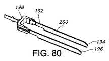
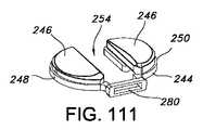
幾つかの実施形態では、往復式骨切除デバイスが提供され、往復式骨切除デバイスは、第1の往復式骨切除ブレード;第2の往復式骨切除ブレード;及び第1及び第2の往復式骨切除ブレードをともに連結するコネクタを含む。幾つかの実施形態では、第1及び第2の往復式骨切除ブレードは細長く、それぞれが近位側端部及び遠位側縁部を含み;コネクタは第1及び第2の往復式骨切除ブレードを、それぞれのブレードの近位側端部の近傍でともに連結する。幾つかの実施形態では、第1及び第2の往復式骨切除ブレードは、それぞれの往復式骨切除ブレードの近位側端部の近傍でともに連結されているのみである。幾つかの実施形態では、第1及び第2の往復式骨切除ブレードはそれぞれが切除面を画成し、切除面は互いに対して実質的に平行に延びている。幾つかの実施形態では、第1及び第2の往復式骨切除ブレードは、互いに向かってバイアスされている。幾つかの実施形態では、第1及び第2の往復式骨切除ブレードのそれぞれが、内側平坦面を含む。幾つかの実施形態では、第1及び第2の往復式骨切除ブレードの内側平坦面は実質的に平滑である。幾つかの実施形態では、第1及び第2の往復式骨切除ブレードは、コネクタに脱着可能に連結されている。幾つかの実施形態では、コネクタは、往復式骨切除デバイスを往復式鋸に固定するための取り付け特徴を含む。幾つかの実施形態では、第1及び第2の往復式骨切除ブレードのそれぞれが、往復式骨切除デバイスを往復式鋸に固定するための取り付け特徴を含む。幾つかの実施形態では、往復式骨切除ブレードの取り付け特徴は、コネクタの取り付け特徴と実質的に同じサイズ及び形状である。幾つかの実施形態では、第1及び第2の往復式骨切除ブレードは、コネクタと一体型である。幾つかの実施形態では、第1及び第2の往復式骨切除ブレードは、脛骨近位部で2つの切断を同時に行うことを容易にするように、互いに対して配置され方向付けられている。幾つかの実施形態では、第1及び第2の往復式骨切除ブレードは、脛骨近位部で2つの垂直な隆起部切断を同時に行うことを容易にするように、互いに対して配置され方向付けられている。 In some embodiments, a reciprocating osteotomy device is provided, the reciprocating osteotomy device comprising: a first reciprocating osteotomy blade; a second reciprocating osteotomy blade; and a first and second reciprocating osteotomy. A connector for connecting the osteotomy blades together; In some embodiments, the first and second reciprocating osteotomy blades are elongate, each including a proximal end and a distal edge; the connector includes first and second reciprocating osteotomy blades Are connected together in the vicinity of the proximal end of each blade. In some embodiments, the first and second reciprocating osteotomy blades are only connected together near the proximal end of each reciprocating osteotomy blade. In some embodiments, the first and second reciprocating osteotomy blades each define a cutting surface, and the cutting surfaces extend substantially parallel to each other. In some embodiments, the first and second reciprocating osteotomy blades are biased toward each other. In some embodiments, each of the first and second reciprocating osteotomy blades includes an inner flat surface. In some embodiments, the inner flat surface of the first and second reciprocating osteotomy blades is substantially smooth. In some embodiments, the first and second reciprocating osteotomy blades are removably coupled to the connector. In some embodiments, the connector includes attachment features for securing the reciprocating osteotomy device to the reciprocating saw. In some embodiments, each of the first and second reciprocating osteotomy blades includes an attachment feature for securing the reciprocating osteotomy device to the reciprocating saw. In some embodiments, the attachment features of the reciprocating osteotomy blade are substantially the same size and shape as the attachment features of the connector. In some embodiments, the first and second reciprocating osteotomy blades are integral with the connector. In some embodiments, the first and second reciprocating osteotomy blades are positioned and oriented with respect to each other to facilitate simultaneous two cuts at the proximal tibia. In some embodiments, the first and second reciprocating osteotomy blades are positioned and oriented relative to each other to facilitate simultaneously performing two vertical ridge cuts at the proximal tibia. It has been.
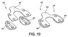
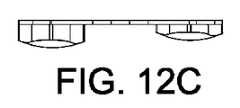
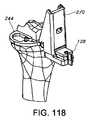
幾つかの実施形態では、前後十字靭帯温存型脛骨ベースプレートが提供され、前後十字靭帯温存型脛骨ベースプレートは、内側ベースプレートウェブ;外側ベースプレートウェブ;及び内側及び外側ベースプレートウェブを連結するブリッジを含み;前後十字靭帯温存型脛骨ベースプレートは、内側ベースプレートウェブと外側ベースプレートウェブとの間の間隙を画成し、間隙は、前十字靭帯接合位置及び後十字靭帯接合位置を含む脛骨隆起部を受けるようなサイズ及び配置である。幾つかの実施形態では、内側及び外側ベースプレートウェブは、内側及び外側脛骨プラトー切除部をそれぞれ参照するための実質的に平坦な下側表面をそれぞれ画成し;実質的に平坦な下側表面は、実質的に同一平面である。幾つかの実施形態では、内側ベースプレートウェブは、内側脛骨トライアルインサートを固定するための少なくとも1つの内側取り付け位置を含み;外側基板ウェブは、外側脛骨トライアルインサートを固定するための少なくとも1つの外側取り付け位置を含む。幾つかの実施形態では、前後十字靭帯温存型脛骨ベースプレートは、内側穿孔面及び外側穿孔面を含む穿孔器を受けるための穿孔器間隙を画成する。幾つかの実施形態では、穿孔器間隙は、実質的にU字形の穿孔器を受けるためのものであり;U字形穿孔器の第1の脚は内側穿孔面を含み、U字形穿孔器の第2の脚は外側穿孔面を含む。幾つかの実施形態では、ベースプレートはまた、穿孔器ガイドを前後十字靭帯温存型脛骨ベースプレートに固定するための少なくとも1つの穿孔器ガイド取り付け位置を含む。幾つかの実施形態では、前後十字靭帯温存型脛骨ベースプレートは、脛骨隆起部の前側面を切除するための切断具を受けるための前側プラトー切除間隙を画成する。幾つかの実施形態では、前側プラトー切除間隙は、ブリッジを通って延びるスロットである。幾つかの実施形態では、前後十字靭帯温存型脛骨ベースプレートは、内側穿孔面及び外側穿孔面を含む実質的にU字形の穿孔器を受けるための穿孔器間隙を画成する。幾つかの実施形態では、ベースプレートはまた、U字形穿孔器及び脛骨隆起部の前側面を切除するための切断具をガイドするためのガイドを固定するための少なくとも1つのガイド取り付け位置を含む。 In some embodiments, an anteroposterior cruciate ligament-preserving tibial baseplate is provided, the anteroposterior cruciate ligament-preserving tibial baseplate including an inner baseplate web; an outer baseplate web; and a bridge connecting the inner and outer baseplate webs; The ligament-preserving tibial baseplate defines a gap between the inner baseplate web and the outer baseplate web, the gap being sized and arranged to receive a tibial protuberance including an anterior cruciate ligament junction location and a posterior cruciate ligament junction location It is. In some embodiments, the medial and lateral baseplate webs define a substantially flat lower surface for reference to the medial and lateral tibial plateau excisions, respectively; Are substantially coplanar. In some embodiments, the medial baseplate web includes at least one medial attachment location for securing the medial tibial trial insert; the medial substrate web is at least one medial attachment location for securing the lateral tibial trial insert. including. In some embodiments, the anteroposterior cruciate ligament-preserving tibial baseplate defines a piercer gap for receiving a piercer including an inner piercing surface and an outer piercing surface. In some embodiments, the perforator gap is for receiving a substantially U-shaped perforator; the first leg of the U-shaped perforator includes an inner perforated surface, and the U-shaped perforator first The two legs include an outer perforated surface. In some embodiments, the base plate also includes at least one perforator guide attachment location for securing the perforator guide to the anteroposterior cruciate ligament-preserving tibial base plate. In some embodiments, the anteroposterior cruciate ligament-preserving tibial base plate defines an anterior plateau excision gap for receiving a cutting tool for excising the anterior aspect of the tibia protuberance. In some embodiments, the anterior plateau excision gap is a slot that extends through the bridge. In some embodiments, the anterior-posterior cruciate ligament-preserving tibial baseplate defines a piercer gap for receiving a substantially U-shaped piercer including an inner piercing surface and an outer piercing surface. In some embodiments, the base plate also includes at least one guide attachment location for securing a guide for guiding a U-shaped perforator and a cutting tool for resecting the anterior side of the tibial ridge.
幾つかの実施形態では、大腿骨遠位部及び脛骨近位部を有する膝関節の前後十字靭帯温存型関節形成術を実施するための方法が提供され、方法は、脛骨の切除された内側及び外側部分を画成するように、脛骨隆起部の周りで脛骨近位部の内側及び外側部分を切除するステップ;脛骨近位部の切除された内側及び外側部分に脛骨トライアルを配置するステップ;及び脛骨近位部の切除された内側及び外側部分に脛骨トライアルを配置するステップの後、脛骨隆起部の前側面を除去するステップを含む。幾つかの実施形態では、方法はまた、脛骨隆起部の前側面を除去するステップの前に、脛骨トライアルを使用して脛骨近位部の切除された内側及び外側部分を評価するステップを含む。幾つかの実施形態では、脛骨の切除された内側及び外側部分を評価するステップは、膝関節の可動域を評価するステップを含む。幾つかの実施形態では、膝関節の可動域を評価するステップは、大腿骨トライアルを脛骨トライアルに対して関節結合するステップを含む。幾つかの実施形態では、脛骨近位部の内側及び外側部分を切除するステップは、水平な内側脛骨プラトー切除部及び水平な外側脛骨プラトー切除部を形成するステップを含む。幾つかの実施形態では、脛骨近位部の内側及び外側部分を切除するステップはさらに、垂直な内側切除部及び垂直な外側切除部を形成するステップを含む。幾つかの実施形態では、方法はまた、脛骨近位部へとキールキャビティを穿孔するステップを含む。幾つかの実施形態では、キールキャビティを穿孔するステップは、脛骨隆起部の前側面を除去するステップの前又は後に行われる。幾つかの実施形態では、脛骨隆起部の前側面を除去するステップは、脛骨隆起部の前側面に水平な切除部及び垂直な切除部を形成するステップを含む。幾つかの実施形態では、方法はまた、ガイドを脛骨トライアルに対して固定するステップを含む。幾つかの実施形態では、ガイドを脛骨トライアルに対して固定するステップは、キールキャビティを穿孔し、脛骨隆起部の前側面に水平な切除部及び垂直な切除部を形成するステップをガイドするためのガイドを固定するステップを含む。幾つかの実施形態では、脛骨近位部の切除された内側及び外側部分に脛骨トライアルを配置するステップは、脛骨トライアルを脛骨近位部に固定するステップを含む。幾つかの実施形態では、脛骨トライアルを脛骨近位部に固定するステップは、脛骨トライアルを脛骨近位部の切除された内側及び外側部分にピン固定するステップを含む。幾つかの実施形態では、脛骨トライアルを脛骨近位部に固定するステップは、脛骨トライアルを脛骨近位部の前側面に固定されたコンポーネントに固定するステップを含む。 In some embodiments, a method is provided for performing an anteroposterior cruciate ligament-preserving arthroplasty of a knee joint having a distal femur and a proximal tibia, the method comprising: Resecting the medial and lateral portions of the proximal tibia around the tibia ridge to define the lateral portion; placing tibial trials on the resected medial and lateral portions of the proximal tibia; and After placing the tibial trial on the resected medial and lateral portions of the proximal tibia, removing the anterior side of the tibia protuberance. In some embodiments, the method also includes evaluating the resected medial and lateral portions of the proximal tibia using a tibial trial prior to removing the anterior aspect of the tibia protuberance. In some embodiments, evaluating the resected medial and lateral portions of the tibia includes assessing the range of motion of the knee joint. In some embodiments, assessing the range of motion of the knee joint includes articulating the femoral trial with the tibial trial. In some embodiments, resecting the medial and lateral portions of the proximal tibia includes forming a horizontal medial tibial plateau excision and a horizontal lateral tibial plateau excision. In some embodiments, resecting the medial and lateral portions of the proximal tibia further includes forming a vertical medial cut and a vertical lateral cut. In some embodiments, the method also includes drilling the keel cavity into the proximal tibia. In some embodiments, the step of drilling the keel cavity is performed before or after the step of removing the anterior aspect of the tibial ridge. In some embodiments, removing the anterior aspect of the tibial protuberance includes forming a horizontal and vertical excision on the anterior aspect of the tibial protuberance. In some embodiments, the method also includes securing the guide relative to the tibial trial. In some embodiments, securing the guide relative to the tibial trial is for guiding the step of drilling the keel cavity to form a horizontal and vertical excision on the anterior side of the tibial protuberance. Including fixing the guide. In some embodiments, placing the tibial trial on the resected medial and lateral portions of the proximal tibia includes securing the tibial trial to the proximal tibia. In some embodiments, securing the tibial trial to the proximal tibia includes pinning the tibial trial to the resected medial and lateral portions of the proximal tibia. In some embodiments, securing the tibial trial to the proximal tibia includes securing the tibial trial to a component secured to the anterior side of the proximal tibia.
幾つかの実施形態では、前後十字靭帯温存型脛骨トライアルベースプレートが提供され、前後十字靭帯温存型脛骨トライアルベースプレートは、前後十字靭帯温存型脛骨インプラントの内側、中心側表面の範囲を示すための内側、中心側基準面を含み、前後十字靭帯温存型脛骨インプラントの内側、外表面の範囲を示すための内側、外表側基準面を含む、内側ベースプレートウェブ;前後十字靭帯温存型脛骨インプラントの外側、中心側面の範囲を示すための外側、中心側基準面を含み、前後十字靭帯温存型脛骨インプラントの外側、外表面の範囲を示すための外側、外側基準面を含む、外側ベースプレートウェブ;及び内側及び外側ベースプレートウェブを連結するブリッジを含み;前後十字靭帯温存型脛骨トライアルベースプレートは、前後十字靭帯温存型脛骨インプラントの最終的な所望の位置を記録するための少なくとも1つの基準位置を画成する。幾つかの実施形態では、基準位置は、骨ピンを受けるための一対の穴である。幾つかの実施形態では、基準位置は、ガイドのための取り付け位置である。幾つかの実施形態では、基準位置は、穿孔器ガイドのための取り付け位置である。幾つかの実施形態では、基準位置は、隆起部切除ガイドのための取り付け位置である。幾つかの実施形態では、基準位置は、穿孔器及び隆起部切除ガイドのための取り付け位置である。幾つかの実施形態では、内側、中心側基準面は、内側ベースプレートウェブを画成するアームの第1の部分であり、内側、外表側基準面は、内側ベースプレートウェブを画成するアームの第2の部分であり;外側、中心側基準面は、外側ベースプレートウェブを画成するアームの第1の部分であり、外側、外表側基準面は、外側ベースプレートウェブを画成するアームの第2の部分である。幾つかの実施形態では、内側及び外側ベースプレートウェブを画成するアームは、内側及び外側脛骨トライアルインサートをそれぞれ受けるように構成されている。幾つかの実施形態では、アームの外表面は前後十字靭帯温存型脛骨インプラントの外形を示す。幾つかの実施形態では、アームの外表面は、前十字靭帯及び後十字靭帯の接合位置を有する脛骨隆起部を受けるための前後十字靭帯温存型脛骨インプラントの間隙の位置を示す。 In some embodiments, an anteroposterior cruciate ligament-preserving tibial trial base plate is provided, wherein the anteroposterior cruciate ligament-preserving tibial trial base plate is medial to indicate the extent of the medial surface of the anteroposterior cruciate ligament-preserving tibial implant; Medial baseplate web, including medial reference plane, medial anteroposterior cruciate ligament-preserving tibial implant, medial to indicate the extent of the external surface, and external surface reference surface; An outer base plate web, including an outer, central reference plane to indicate the extent of the anteroposterior cruciate ligament-preserving tibial implant, an outer to indicate the extent of the outer surface, an outer reference plane; Including a bridge connecting the web; an anteroposterior cruciate ligament-preserving tibial trial base plate The final desired position of the posterior cruciate ligament-retaining tibial implant defines at least one reference position for recording. In some embodiments, the reference position is a pair of holes for receiving bone pins. In some embodiments, the reference position is an attachment position for the guide. In some embodiments, the reference position is an attachment position for the perforator guide. In some embodiments, the reference position is an attachment position for the ridge resection guide. In some embodiments, the reference position is an attachment position for the perforator and the ridge resection guide. In some embodiments, the inner, central reference plane is a first portion of an arm that defines an inner baseplate web, and the inner, outer reference plane is a second portion of an arm that defines an inner baseplate web. The outer, central reference plane is the first part of the arm that defines the outer baseplate web, and the outer, outer reference plane is the second part of the arm that defines the outer baseplate web. It is. In some embodiments, the arms that define the medial and lateral baseplate webs are configured to receive medial and lateral tibial trial inserts, respectively. In some embodiments, the outer surface of the arm represents the contour of a anteroposterior cruciate ligament-preserving tibial implant. In some embodiments, the outer surface of the arm indicates the position of the gap in the anteroposterior cruciate ligament-preserving tibial implant for receiving a tibial protuberance having an anterior cruciate ligament junction location.
幾つかの実施形態では、脛骨近位部にキールキャビティを形成するための骨除去器械が提供され、骨除去器械は、脛骨近位部にキールキャビティを画成するための骨除去機器;及び骨除去機器の脛骨近位部への動作をガイドするためのガイドを含み、ガイドは、脛骨近位部の内側プラトー切除部及び外側プラトー切除部を参照するための少なくとも1つの実質的に平坦な基準面;少なくとも1つの実質的に平坦な基準面へと非垂直な角度で延びる傾斜したガイドを含み、傾斜したガイドは脛骨近位部へと非垂直な角度で骨除去機器をガイドするように、骨除去機器と相互作用する形状である。幾つかの実施形態では、骨除去機器は、少なくとも1つの切除縁部を含む。幾つかの実施形態では、少なくとも1つの切除縁部は、実質的にU字形の断面である。幾つかの実施形態では、傾斜されたガイドは少なくとも1つの実質的に平坦な基準面に非垂直な角度で、及び少なくとも1つの実質的に平坦な基準面に鈍角の角度で延びる。幾つかの実施形態では、傾斜したガイドは、骨除去機器の動作を制約する捕捉面を含む。幾つかの実施形態では、骨除去機器は、細長い突起部を含み;捕捉面は細長い突起部を捕捉する。幾つかの実施形態では、少なくとも1つの実質的に平坦な基準面は、前後十字靭帯温存型脛骨トライアルベースプレートの下側表面である。幾つかの実施形態では、前後十字靭帯温存型脛骨トライアルベースプレートは、内側ベースプレートウェブと外側ベースプレートウェブとの間の間隙を画成し、間隙は、前十字靭帯接合位置及び後十字靭帯接合位置を含む脛骨隆起部を受けるようなサイズ及び配置である。幾つかの実施形態では、ガイドはさらに、前後十字靭帯温存型脛骨トライアルベースプレートの下側表面と実質的に平行な、又は同一平面である平面で、第2の切断具の脛骨隆起部の前側部分への動作をガイドするように配置され方向付けられた水平ガイドを含む。幾つかの実施形態では、ガイドはさらに、前後十字靭帯温存型脛骨トライアルベースプレートの下側表面に実質的に平行でない平面で、第2の切断具の脛骨隆起部の前側部分への動作をガイドするように配置され方向付けられた垂直ガイドを含む。 In some embodiments, a bone removal instrument is provided for forming a keel cavity in the proximal tibia, the bone removal instrument defining a bone removal device for defining the keel cavity in the proximal tibia; and bone A guide for guiding movement of the removal device to the proximal tibia, wherein the guide is at least one substantially flat reference for referencing the inner and outer plateau resections of the proximal tibia A sloped guide that extends at a non-perpendicular angle to at least one substantially flat reference plane so that the tilted guide guides the bone removal device at a non-perpendicular angle to the proximal tibia, The shape interacts with the bone removal device. In some embodiments, the bone removal device includes at least one cutting edge. In some embodiments, the at least one cutting edge has a substantially U-shaped cross section. In some embodiments, the tilted guide extends at an angle that is non-perpendicular to at least one substantially flat reference surface and at an obtuse angle to at least one substantially flat reference surface. In some embodiments, the tilted guide includes a capture surface that constrains the operation of the bone removal device. In some embodiments, the bone removal device includes an elongated protrusion; the capture surface captures the elongated protrusion. In some embodiments, the at least one substantially flat reference surface is the lower surface of the anterior-posterior cruciate ligament-preserving tibial trial base plate. In some embodiments, the anteroposterior cruciate ligament-preserving tibial trial baseplate defines a gap between the inner baseplate web and the outer baseplate web, the gap including an anterior cruciate ligament junction location and a posterior cruciate ligament junction location. It is sized and arranged to receive the tibial protuberance. In some embodiments, the guide is further in a plane that is substantially parallel to or coplanar with the lower surface of the anteroposterior cruciate ligament-preserving tibial trial baseplate, A horizontal guide arranged and oriented to guide the movement to In some embodiments, the guide further guides the movement of the second cutting tool to the anterior portion of the tibial protuberance in a plane that is not substantially parallel to the lower surface of the anteroposterior cruciate ligament-preserving tibial trial baseplate. Vertical guides arranged and oriented in this manner.
幾つかの実施形態では、脛骨近位部の脛骨隆起部の前側部分を除去するための骨除去器械が提供され、骨除去器械は、脛骨隆起部の前側部分を除去するための少なくとも1つの骨除去機器;及び骨除去機器の脛骨近位部への動作をガイドするためのガイドを含み、ガイドは、脛骨近位部の内側プラトー切除部を参照するための実質的に平坦な内側基準面;及び脛骨近位部の外側プラトー切除部を参照するための実質的に平坦な外側基準面;及び実質的に平坦な内側及び外側基準面と実質的に平行な、又は同一平面である平面で、骨除去機器の脛骨隆起部の前側部分への動作をガイドするように配置された水平ガイドを含み;ガイドは内側及び外側基準面の間の間隙を画成し、間隙は、少なくとも前十字靭帯接合位置を含む脛骨隆起部の一部分を受けるようなサイズ及び配置である。幾つかの実施形態では、ガイドはさらに、実質的に平坦な内側及び外側基準面に実質的に平行でない、又は同一平面でない平面で、第2の骨除去機器の脛骨隆起部の前側部分への動作をガイドするように配置された垂直ガイドを含む。幾つかの実施形態では、ガイドはさらに、実質的に平坦な内側及び外側基準面に実質的に平行でない、又は同一平面でない平面で、骨除去機器の脛骨隆起部の前側部分への動作をガイドするように配置された垂直ガイドを含む。幾つかの実施形態では、垂直ガイドは、実質的に平坦な内側及び外側基準面に実質的に垂直な平面で、骨除去機器の動作をガイドするように配置されている。幾つかの実施形態では、ガイドは、前後十字靭帯温存型脛骨トライアルベースプレート及び前後十字靭帯温存型脛骨トライアルベースプレートに対して固定位置で脱着可能に配置されたモジュール式ガイドを含む、ガイドアセンブリを含む。 In some embodiments, a bone removal instrument is provided for removing the anterior portion of the tibial protuberance of the proximal tibia, the bone removal instrument comprising at least one bone for removing the anterior portion of the tibial protuberance. A removal device; and a guide for guiding movement of the bone removal device to the proximal tibia, wherein the guide is a substantially flat inner reference surface for reference to the medial plateau resection of the proximal tibia; And a substantially flat outer reference surface for reference to the outer plateau excision of the proximal tibia; and a plane that is substantially parallel to or coplanar with the substantially flat inner and outer reference surfaces; A horizontal guide arranged to guide movement of the bone removal device to the anterior portion of the tibial protuberance; the guide defines a gap between the medial and lateral reference planes, the gap being at least an anterior cruciate ligament junction A portion of the tibial protuberance including location It is sized and arranged to receive. In some embodiments, the guide is further directed to the anterior portion of the tibial protuberance of the second bone removal device in a plane that is not substantially parallel or non-coplanar to the substantially flat medial and lateral reference surfaces. Includes a vertical guide arranged to guide movement. In some embodiments, the guide further guides the movement of the bone removal device to the anterior portion of the tibial protuberance in a plane that is not substantially parallel to or coplanar with the flat inner and outer reference planes. Including a vertical guide arranged to. In some embodiments, the vertical guide is arranged to guide the operation of the bone removal device in a plane that is substantially perpendicular to the substantially flat inner and outer reference planes. In some embodiments, the guide includes a guide assembly including a anteroposterior cruciate ligament-preserving tibial trial baseplate and a modular guide removably disposed in a fixed position relative to the anteroposterior cruciate ligament-preserving tibial trial baseplate.
図面に示す非限定的な実施形態の以下の説明は、単に例示的な性質のものであり、本明細書に開示された発明、その用途、又は使用をどのようにも制限するためのものではない。図1〜図30は、人工膝関節形成術中に大腿骨インプラントのために大腿骨遠位部を準備するための方法及び装置の実施例を示す。図31〜図162は、人工膝関節形成術中に脛骨インプラントのために脛骨近位部を準備するための方法及び装置の実施例を示す。 The following description of non-limiting embodiments shown in the drawings is merely exemplary in nature and is not intended to limit the invention, its application, or use disclosed herein in any way. Absent. 1-30 illustrate an embodiment of a method and apparatus for preparing a distal femur for a femoral implant during knee arthroplasty. 31-162 illustrate an embodiment of a method and apparatus for preparing the proximal tibia for a tibial implant during knee arthroplasty.
大腿骨の切除
軟部組織の大腿骨接合位置と、脛骨及び大腿骨間の関節との間には強い関係がある。一般的に、生来の軟部組織構造よりも運動制御及び安定性のために考慮された手段に大きく依存する膝インプラント設計では、患者の運動学的アウトカムは、例えば、生来の大腿骨関節面及び埋め込まれた大腿骨関節面の下側/上側位置間の不一致に対する感度は、より低いことが明らかにされているが、それでもやはり、そのような不一致は、場合によっては重大な影響を及ぼすことがある。しかし、運動制御及び安定性をもたらすために(例えば、前後十字靭帯温存型インプラントで)、より多くの生来の構造が保存されるとき、少なくとも幾つかの状況では、大腿骨関節ラインの保存が患者のアウトカムにとってより重要となることがある。Resection of the femur There is a strong relationship between the femoral joint location of the soft tissue and the joint between the tibia and the femur. In general, in knee implant designs that rely more on the means considered for motion control and stability than the native soft tissue structure, the patient's kinematic outcome is, for example, the natural femoral joint surface and implant Although the sensitivity to inconsistencies between the inferior / upper position of a given femoral joint surface has been shown to be lower, nonetheless, such inconsistencies can still have a significant impact in some cases . However, when more native structures are preserved to provide motion control and stability (eg, with anteroposterior cruciate ligament-preserving implants), at least in some situations, preservation of the femoral joint line is a patient May be more important to the outcome of
現在、慣例では、大腿骨内側顆部からの切除の深さを測定するよりも、大腿骨遠位部を溝の高さで切除することが好まれている。しかし、少なくとも場合によっては、大腿骨遠位部が大腿骨遠位部インプラントの厚さ以外の高さで切除される傾向に対処する方法及び装置を使用することが好ましい場合がある。例えば、遠位端の内側(及び/又は外側)顆部から測定した大腿骨遠位部インプラントの厚さと等しい量を切除することが好ましいことがあり、これは後十字靭帯及び/又は前十字靭帯の大腿骨上の中心側接合位置に、より良く対応することができる。また、少なくとも場合によっては、伸展空間及び弛緩の早期のトライアル及び評価を可能にする方法及び装置を使用することが好ましい場合もある。以下では、そのような方法及び装置の幾つかの実施例を説明する。 Currently, it is preferred to resect the distal femur at the groove height rather than measuring the depth of resection from the medial condyle of the femur. However, at least in some cases, it may be preferable to use a method and apparatus that addresses the tendency of the distal femur to be resected at a height other than the thickness of the distal femoral implant. For example, it may be preferable to excise an amount equal to the thickness of the distal femoral implant measured from the medial (and / or lateral) condyle of the distal end, which is the posterior and / or anterior cruciate ligament. It is possible to better cope with the center side joint position on the femur. Also, at least in some cases, it may be preferable to use methods and devices that allow early trial and evaluation of extension space and relaxation. In the following, some examples of such methods and apparatus are described.
以下に述べる方法のいくつかは、大腿骨及び脛骨の自由度を同時に解決するのではなく、最初に大腿骨を、その後に脛骨を準備することによって、人工膝関節形成術の複雑さも軽減する。脛骨の切除の前に大腿骨の切除をすべて完了することによって、外科医は一組の固定値を得られ、それに基づいて残りの脛骨の自由度を判断することができる。以下に述べる幾つかの方法によってもたらされる、大腿骨を最初に準備することの別の利点は、正常な運動ができるようにすることである。正常な運動のためには、大腿骨インプラントは一般に、生来の体内構造(例えば、本来の軟部組織及び生来の脛骨軟骨)に十分に順応し関節結合しなければならない。大腿骨の切除ステップを脛骨の切除ステップから分離することによって、外科医は、生来の大腿骨の体内構造によってもたらされる入力変数以外の入力変数によらずに、大腿骨の切除を判断する。 Some of the methods described below also reduce the complexity of knee arthroplasty by preparing the femur first and then the tibia instead of solving the femoral and tibia degrees of freedom simultaneously. By completing all femoral resections prior to the tibial resection, the surgeon can obtain a set of fixed values based on which the degree of freedom of the remaining tibia can be determined. Another advantage of initially preparing the femur, provided by several methods described below, is to allow normal movement. For normal movement, femoral implants must generally conform and articulate well with native anatomy (eg, native soft tissue and native tibial cartilage). By separating the femoral resection step from the tibia resection step, the surgeon determines the femoral resection regardless of input variables other than the input variables provided by the native femoral anatomy.
以下に述べる実施形態のいくつかにおいて、脛骨の前に大腿骨遠位部を準備することの第3の利点は、外科医が、大腿骨側を準備した後であっても時間の延長又は骨損失を殆ど又は全く伴うことなく、後側安定化十字靭帯温存手術、又は前後十字靭帯温存手術を実施する柔軟性をまだ有することである。 In some of the embodiments described below, a third advantage of preparing the distal femur in front of the tibia is that the surgeon can prolong time or lose bone even after preparing the femoral side. And still have the flexibility to perform posterior stabilized cruciate ligament-sparing surgery or anteroposterior cruciate ligament-sparing surgery.
しかし、以下に述べる方法及び装置の多くは、大腿骨を最初に準備する技術、又は上記の利点をすべて達成する技術のみに限定されない。 However, many of the methods and devices described below are not limited to techniques that initially prepare the femur, or techniques that achieve all of the above advantages.
図1〜図9は、図1に示す大腿骨遠位部10及び図2に示す脛骨近位部12に関してそのような方法を実行するための、骨遠位部の切除を最初に行う1つの方法及び装置を示す。 FIGS. 1-9 show one of the first resections of the distal bone to perform such a method on the
図1は、切除前の大腿骨遠位部10を示す。図3は、大腿骨遠位部10の切除面14を画成する切除後の大腿骨遠位部10を示す。幾つかの実施形態では、切除面14は、大腿骨遠位部10に最終的に埋め込むために、大腿骨インプラント16の遠位側の厚さとほぼ等しい深さになる。適切な大腿骨インプラント16の1つの非限定的な実施例が図7a及び7dに示されている。大腿骨遠位部の切除は、従来の又は従来と異なる技術及び装置を使用して、実施することができる。例えば、往復式又は振動式の鋸又は他の切除デバイスをガイドして大腿骨遠位部の切除部を形成するように、従来の切除ブロック(図示せず)を髄内管を使用して操作し、及び/又は、1つ又は複数の(例えば2つの)平行なピンで大腿骨遠位部にピン固定することができる。場合によっては、大腿骨遠位部の切除部を再切除するために同じ切除ブロック又は異なる切除ブロックを再び取り付けることが必要になる場合、ピンを大腿骨遠位部10に残すことが望ましいことがあり得る。 FIG. 1 shows the
図4〜図8は、大腿骨遠位部トライアル18及び大腿骨遠位部10の切除面14と脛骨近位部12の非切除面(図2に示す脛骨近位部12の非切除面20など)との間への大腿骨遠位部トライアル18の挿入を示す。図4〜図8に示すように、大腿骨遠位部トライアル18は、上側の平坦な表面22及び下側の湾曲した湾曲した表面24を含む。上側の平坦な表面22は大腿骨遠位部10の切除面14に接触するように構成されている。内側顆部の表面26及び外側顆部の表面28を含む下側の湾曲した表面24は、少なくともいくらかの関節角度で脛骨近位部12の非切除面20に接触するためのものである。上側の平坦な表面22は、大腿骨遠位部10の切除面14を形成し取り囲む骨との摩擦を向上させるために、平坦で平滑とし、又は表面処理することができる。図7a〜図7fに示すように、図4〜図8の大腿骨遠位部トライアル18は、大腿骨インプラント16、特に大腿骨インプラント16の下側部分30の少なくとも一部(図7c及び図7eに示す)によって画成される形状及び厚さの少なくとも一部を実質的に複製する。 4-8 show the
図4〜図8に示す実施形態では、大腿骨インプラント16及び大腿骨遠位部トライアル18は、前後十字靭帯温存手術で使用されるように設計されている。例えば、図6に示すように、大腿骨遠位部トライアル18は実質的にU字形であり、脛骨近位部12の脛骨隆起部40の少なくとも一部分(図2に示す)を受けるための内側顆部の表面26と外側顆部の表面28との間の間隙38を画成する。脛骨隆起部40は前十字靭帯及び後十字靭帯の接合位置を含む。大腿骨遠位部トライアル18の間隙38は、大腿骨遠位部トライアル18が大腿骨遠位部10の切除面14と脛骨近位部12の非切除面20との間に挿入されるとき、靭帯との実質的な干渉を避けるようなサイズ及び配置となっており、そのような実施例が図8に示されている。 In the embodiment shown in FIGS. 4-8, the
図示された大腿骨遠位部トライアル18はまた、様々な器械及び他の装置を連結するための取り付け位置32(図6参照)も含む。例えば、図8に示すように、取り付け位置32を使用してハンドル34を連結することができ、これを使用して、図示されている髄外アラインメントロッド36など、他の器械を連結することができる。図6に示すように、取り付け位置32は、ハンドル34などの部品を(例えば、回転しない)固定角度位置で固定できるようにする形状(限定はされないが、例えば非円形)を含むことができる。部品を固定角度位置で固定するために、取り付け位置32に関して他の機構を使用することもできる。例えば、取り付け位置32は、幾つかのコンピュータ支援膝手術で使用される基準構造の取り付けを容易にすることができる。取り付け位置32に連結することができる他の器械及び他の装置の実施例は、以下で詳細に説明する。 The illustrated distal
図8及び図9は、大腿骨遠位部トライアル18を使用して大腿骨遠位部の切除部を評価することができる1つの方法を示す。図8は、切除された大腿骨遠位部10と切除されていない脛骨近位部12との間の空間に挿入された大腿骨遠位部トライアル18を示す。図8には明示的に示されていないが、膝関節の大腿骨遠位部10及び脛骨近位部12は、内側側副靭帯、外側側副靭帯、及び膝蓋腱などの他の体内構造と同様に、前十字靭帯及び後十字靭帯によって連結されている。大腿骨遠位部トライアル18を関節腔へと挿入することによって、外科医は、大腿骨遠位部の切除部を評価することができる。 FIGS. 8 and 9 illustrate one method in which a distal femoral resection can be evaluated using the distal
例えば、大腿骨遠位部トライアル18が、大腿骨インプラント16の下側部分30の少なくとも幾つかの幾何学的形状の形及び厚さを実質的に複製するものである場合、及び大腿骨遠位部10の切除面14が大腿骨インプラント16の遠位側の厚さとほぼ等しい深さで切除された場合、外科医は、手術が完了し、大腿骨インプラント16が埋め込まれ、及び/又は屈曲拘縮について評価することができるようになった後、膝関節の予想される緊張又は弛緩を(上記の靭帯及び腱の1つ又は複数の緊張又は弛緩を考慮して)評価することができる。 For example, if the distal
図9は、外科医が屈曲拘縮について膝関節を評価することができる方法を概略的に示す。脛骨近位部12に対する大腿骨遠位部10の配置を概略的に示す図9に示されている技術では、大腿骨遠位部トライアル18が切除された大腿骨遠位部と切除されていない脛骨近位部との間に挿入された後、膝関節は、膝関節によって可能な最大伸展量まで伸展することができる。可能な最大伸展度が所望の伸展度より小さい、自然の健康な膝関節の伸展度より小さい、及び/又は患者の手術前の膝関節の伸展度より小さい場合(図9の点線300によって概略的に示す)、屈曲拘縮、及び大腿骨遠位部のより深い切除が指示される(例えば、膝関節が「きつすぎる」)ことを外科医に示唆することができる。そのような場合、切除ブロックを取り付け直すことができ、同じ又は異なる大腿骨遠位部トライアルを使用して再評価するために、大腿骨遠位部の切除部を再切除することができる。最大伸展が十分である場合(図9の点線302によって概略的に示す)、大腿骨遠位部の切除の高さが十分であり、再切除する必要がないことを外科医に示唆することができる。屈曲拘縮と十分な伸展との間の境界線(図9の実線304によって概略的に示す)は、図9には約0度の屈曲で起きるものとして示されているが、境界線は必ずしもその位置である必要はなく、患者の特定の環境又は他の要因によって、0度より大きい又は小さい屈曲とすることもできることが理解されよう。 FIG. 9 schematically illustrates how a surgeon can evaluate a knee joint for flexion contractures. In the technique shown in FIG. 9 which schematically illustrates the placement of the
図4〜図9に示す実施形態の大腿骨遠位部トライアル18の1つの利点は、脛骨を切除する必要なしに大腿骨遠位部トライアル18を使用することができることである。人工膝関節形成術において切除の間隙バランス及び他の評価に使用される多くの従来のスペーサーブロックは、正常に機能するためには、脛骨及び大腿骨の両方を少なくとも1つ切除する必要がある。一方、図4〜図9に示す大腿骨遠位部トライアル18は、脛骨近位部12の非切除面20に対する大腿骨遠位部10の切除面14の評価を容易にし、それにより切除の高さについての完全な情報がもたらされる。従来のスペーサーブロックは、脛骨の切除に対する大腿骨の切除を測定するので、切除部間の間隔についての情報を提供するだけであり、膝関節の他の重要な体内構造に対する大腿骨の切除部の関節ラインの向き及び位置についての情報は提供しない。 One advantage of the distal
従って、脛骨近位部を切除する前に大腿骨のすべてではないが少なくとも1つの切除を行う方法では、図4〜図9に示す大腿骨遠位部トライアル18を使用して、大腿骨遠位部の切除の高さについての情報を、従来のスペーサーブロックより術中早期に提供することができる。そのような情報を術中早期に入手することによって、不良なアウトカム及び手術時間の延長を招くことがあるエラーが伝搬する可能性が低減される。 Thus, in a method of performing at least one but not all of the femur before resecting the proximal tibia, a
従来のスペーサーブロックを使用する多くの従来の技術に対する、図4〜図9に図示された方法の別の利点は、これらの従来の技術及びスペーサーが、伸展空間に「偽の弛緩」を生成することができることである。顆部の後側部分は、膝関節を制限及び他の方法で膝関節と相互作用する様々な体内構造にいくらかの緊張をもたらす場合があるので、例えば、後側顆部を切除した後、従来のスペーサーブロックを使用して屈曲及び伸展の間隙を調べるとき、伸展の偽の弛緩を一般的に使用することができる。本明細書で提供される大腿骨遠位部トライアルを使用することによって、使用者は、正しいフィードバックがもたらされる可能性が最も高い環境で、伸展弛緩を測定するように義務付けられる。 Another advantage of the method illustrated in FIGS. 4-9 over many conventional techniques that use conventional spacer blocks is that these conventional techniques and spacers create “false relaxation” in the extension space. Be able to. The posterior part of the condyle may limit the knee joint and cause some tension in various body structures that interact with the knee joint in other ways, for example, after resection of the posterior condyle When using a spacer block to examine the flexion and extension gaps, false relaxation of extension can generally be used. By using the distal femoral trial provided herein, the user is obliged to measure stretch relaxation in an environment that is most likely to provide correct feedback.
上記の方法及び装置を使用して、他の方法で大腿骨遠位部の切除部を評価することができることが、当業者には容易に理解できるであろう。例えば、幾つかの実施形態では、大腿骨遠位部トライアル18によって外科医は、(例えば、患者の体内構造の他の実質的な切除又は破砕前に)特定の患者について前後十字靭帯温存型インプラント及び手術の適切性、又は前後十字靭帯を犠牲にする後十字温存手術(例えば、後側安定化インプラント)、又は他のインプラント/手術を、代わりに遂行するべきかどうかを手術の初期段階に評価することができる。上記又は他の評価方法との組み合わせでは、大腿骨遠位部トライアル18は、機械的及び構造的整列の可視化がしやすいように、ハンドル34及び髄外アラインメントロッド36(例えば、図8に示すものなど)と結合することができる。さらに他の実施形態では、目的の大腿骨インプラントを複製し、又は実質的に複製するもの以外の大腿骨遠位部トライアルを使用して、他の方法で膝関節の遠位側切除部又は他の面を評価することができる。 One skilled in the art will readily appreciate that the above methods and apparatus can be used to evaluate the distal femoral resection in other ways. For example, in some embodiments, the distal
図31〜図33に示す実施形態など、幾つかの実施形態では、大腿骨遠位部トライアル18又は他のタイプの大腿骨のトライアルは、脛骨近位部12の切除のための適切な深さの識別を容易にすることができる。図31は、脛骨の切除の所望の深さ又は人工膝関節形成術に関する他の情報を示すように、(手術用マーカー又は他の装置を使用して)脛骨近位部12に印100をマーキングするための、ハンドル34に取り付けられた脛骨の深さゲージ98を示す。図示されていないが、幾つかの実施形態では、印100を付ける前に、膝関節が正常な伸展又は屈曲レベルになり、又は他の方法で適切に整列されるように、髄外アラインメントロッド36又は他のアラインメントを容易にするデバイスを、連結することが望ましい場合もある。 In some embodiments, such as the embodiment shown in FIGS. 31-33, the distal
図32及び33は、脛骨の深さを示すために大腿骨遠位部トライアル18(図32)又は別の大腿骨のトライアル80(図33)とともに使用することができる他の装置を示す。図32は、関連するハンドル34を介して大腿骨遠位部トライアル18に連結されたアラインメントブロック102を示す。アラインメントブロック102を使用して、脛骨近位部12に印を付けることができ、又は幾つかの実施形態では、脛骨近位部12に直接ピン固定することができる。大腿骨遠位部トライアル18とアラインメントブロック102との間の連結によって、アラインメントブロック102は、大腿骨遠位部のトライアル18に対して固定角度位置に配置されるので、大腿骨遠位部トライアル18及び関連するハンドル34の位置(及び少なくともある程度の膝関節の屈曲又は伸展度)によって、その上側/下側配置、その内反/外反角度、及び後側傾斜など、脛骨近位部12に関するアラインメントブロック102の配置及び向きを制御する。しかし、屈曲/伸展による膝関節の動作は、少なくとも一部が、脛骨近位部12に関するアラインメントブロック102のこれらの位置及び向きの一部に影響することがある。従って、幾つかの実施形態では、髄外アラインメントロッド36(図8に示す)又はインジケータ104(図32に示す)も使用して、脛骨近位部12でのアラインメントブロック102の正常な、及び/又は所望の配置を確認することが望ましい場合もある。 FIGS. 32 and 33 show other devices that can be used with distal femur trial 18 (FIG. 32) or another femoral trial 80 (FIG. 33) to show the depth of the tibia. FIG. 32 shows the
図10〜図13は、異なる大腿骨遠位部トライアル18のセット42を含む手術用キットの実施形態を示す。例えば、図11a〜図11cは、異なる大腿骨インプラントサイズを擬似的に実現する大腿骨遠位部トライアル18のセット42を概略的に示す。図示されているセットは、大腿骨遠位部トライアル18の3つのサイズを含む:内側−外側幅のサイズが1〜2、及び内側顆部の厚さが9.5mmの大腿骨インプラントをシミュレートする第1のサイズ;内側−外側幅のサイズが3〜8、及び内側顆部の厚さが9.5mmの大腿骨インプラントをシミュレートする第2のサイズ;及び内側−外側幅のサイズが9〜10、及び内側顆部の厚さが11.5mmの大腿骨インプラントをシミュレートする第3のサイズ。幾つかの実施形態では、それぞれの大腿骨遠位部トライアル18の顆部半径は、サイズ範囲内のそれぞれの顆部半径の平均とほぼ等しくすることができる。例えば、サイズ1〜2の大腿骨遠位部トライアルは、サイズ1及びサイズ2の内側及び外側半径の平均とそれぞれほぼ等しい内側及び外側顆部半径を有することができる。他の実施形態では、大腿骨遠位部トライアルの顆部半径は、特定の大腿骨インプラントのサイズ範囲内の最小又は最大顆部半径とほぼ等しくすることができる。例えば、第2の大腿骨遠位部トライアル18(大腿骨サイズ3〜8を代表する)は、サイズ3(サイズ範囲内で最小)又はサイズ8(サイズ範囲内で最大)の大腿骨インプラントとほぼ等しい内側及び外側顆部半径を有することができる。 10-13 illustrate an embodiment of a surgical kit that includes a set 42 of different distal
別の実施例では、大腿骨遠位部トライアル18のセットが手術用キット内に設けられ、それぞれの大腿骨遠位部トライアルは特定の大腿骨インプラントサイズに正確に対応するサイズを有する。この実施例では、より多くの大腿骨遠位部トライアルを手術用キットに設ける必要がある場合がある。しかし、それぞれの大腿骨遠位部トライアルが単一の大腿骨インプラントサイズを代表する場合、単一の大腿骨遠位部トライアルで内側及び外側遠位側半径を平均化し、又は全サイズ範囲を代表する内側−外側幅を選択する必要がない。従って、より多数の大腿骨遠位部トライアルを手術用キットに設けることと引き換えに、弛緩及び最大伸展の評価をより正確に行うことができる。 In another example, a set of distal
図10は、モジュール式の大腿骨遠位部トライアル18のセット42を示す。図10の実施形態では、それぞれの大腿骨遠位部トライアル18が、特定のサイズの大腿骨遠位部トライアル18を形成するように、一対のモジュール式シム46に連結することができるベースプレート44を含む。 FIG. 10 shows a set 42 of modular distal
図12及び13は、ベースプレート44及びシム46を使用して大腿骨遠位部トライアル18の特定の形状を変化させる、モジュール式大腿骨遠位部トライアルのセットを示す。例えば、図12a〜図12hの実施形態では、シム46は、大腿骨遠位部トライアルの内側及び外側顆部の部分の厚さを修正することを容易にする。幾つかの使用では、図12に示すモジュール式大腿骨遠位部トライアルのセットは、大腿骨遠位部の切除部を評価しながら、脛骨及び/又は大腿骨の関節面の軟骨及び骨の欠陥、異常、又は他の偏位(患者特有の大腿骨顆部の形態)に対応する助けとなることができる。図13a〜図13lは、大腿骨遠位部トライアルの内反/外反角度又は屈曲/伸展角度など、大腿骨遠位部トライアルのある角度形状を変化させることに加えて、又はその代わりに、モジュール式ベースプレート44を使用して大腿骨遠位部トライアルの全体的な厚さを変えることができるモジュール式大腿骨遠位部トライアルのセットを示す。図14a〜図14dは、ベースプレート44自体をモジュール式とすることができ、ベースプレートの内側及び外側部分を他の部分とは関係なく変えることができる、大腿骨遠位部トライアルのセットの別の実施例を示す。幾つかの実施形態では、図14a〜図14dに示すベースプレート44を、単顆人工膝関節形成術で使用するためなど、様々な目的のために、個々に(例えば、内側部分のみ又は外側部分のみ)使用することができる。 FIGS. 12 and 13 show a set of modular distal femoral trials that use a
さらに他の実施形態では、大腿骨遠位部トライアルは、大腿骨遠位部トライアルのサイズ、厚さ、角度形状又は他の形状を調整するように、大腿骨遠位部トライアルの一部分を他の部分に対して拡張及び/又は縮小することができる調整機構を含むことができる。 In yet other embodiments, the distal femoral trial may include a portion of the distal femoral trial to adjust the size, thickness, angular shape, or other shape of the distal femoral trial. An adjustment mechanism can be included that can be expanded and / or contracted relative to the portion.
図15〜図20に示すように、幾つかの実施形態では、大腿骨遠位部10の切除面14に対する大腿骨遠位部トライアル18の内旋/外旋、前側/後側位置、及び/又はサイズを測定及び/又は設定するためのゲージとして、大腿骨遠位部トライアル18を使用することができる。この測定機能は、手術終了時に大腿骨インプラント16を大腿骨遠位部10上でどのような配置及び向きとするかについて、外科医が可視化又は計画しやすくすることができる。 As shown in FIGS. 15-20, in some embodiments, the internal / external rotation of the
図15〜図20に示す大腿骨遠位部トライアル18は、大腿骨遠位部10及び大腿骨遠位部10の切除面14に対する大腿骨遠位部トライアル18の位置を示す様々な基準を含む。例えば、(図17に示すように)大腿骨遠位部トライアル18の下側の湾曲した表面の後縁部48を使用して、大腿骨遠位部10の切除面14の後縁部50を参照することができる。パドル56が、大腿骨遠位部10の内側及び外側顆部58の後側部分を参照するために、大腿骨遠位部トライアル18の後側部分から実質的に垂直に延びることができる。大腿骨遠位部トライアル18を通って延びる窓部52を使用して、大腿骨遠位部10の内側及び外側上顆54を参照することができる。別の窓又は窓部60を使用して、大腿骨遠位部10の前後軸62及び/又は大腿骨遠位部10の切除面14の中心前側V字点64に対する大腿骨遠位部トライアル18の位置を示すことができる。大腿骨遠位部トライアル上の印など、他の基準をそれらのみで、又は窓部、パドル及び上記の他の基準と併せて、使用することもできる。幾つかの実施形態では、大腿骨遠位部トライアル18の前側表面又は縁部を使用して、大腿骨遠位部の切除面14の前側縁部を参照することができる。 The
幾つかの実施形態では、大腿骨遠位部10に対する大腿骨遠位部トライアル18の内旋/外旋を測定するために、後縁部48、窓部52、パドル56、窓部60及び/又は他の基準を(様々な組み合わせで)使用することができ、場合によっては、これを使用して、大腿骨遠位部10上での大腿骨インプラント16の最終的な配置を可視化及び/又は計画することができる。 In some embodiments, to measure the internal / external rotation of the
図15〜図20に示す大腿骨遠位部トライアル18は、大腿骨のサイズ及び前後位置を測定するために使用することもできる。後縁部48、パドル56、及び窓部60など、上記の同じ基準の多くは、サイズ及び位置を測定するために使用することができる。例えば、大腿骨インプラントの内側−外側サイジングの識別又は評価に有用とすることができる、切除面14の内側及び外側縁部68に対する大腿骨遠位部トライアル18の内側及び外側縁部66の相対位置、又は内側及び外側縁部68に対する展開可能なアーム70の相対位置(又は、展開可能なアーム上の図示しない印)などの、大腿骨遠位部トライアル上の他の基準も有用とすることができる。図19及び図20に示すように、大腿骨遠位部10の前側皮質74の位置を参照するために、前側スタイラス72を、(図19及び図20に示す実施形態では、前側スタイラス72を大腿骨遠位部トライアル18の取り付け位置32に配置することによって)大腿骨遠位部トライアル18に結合することができる。 The
大腿骨遠位部に対する大腿骨遠位部トライアル18の所望の位置及び/又は回転が達成された後、所望であれば、外科医は、手術中にさらに使用するための情報を記録するために、大腿骨遠位部に印を作成することができる。例えば、図15〜図20に示す大腿骨遠位部トライアル18は、大腿骨遠位部上に印を付け、又は設置することができる骨ピン、手術用マーカー又は切除デバイスを受ける開口78を含む。 After the desired position and / or rotation of the distal
幾つかの実施形態では、弛緩及び伸展の評価後、又は大腿骨遠位部の切除の他の面が完了した後、図21に示すように従来の「箱形骨切除」を大腿骨遠位部10に形成することができる。箱形骨切除は、大腿骨遠位部の切除部にファイブインワン切除ブロックを配置して、内側及び外側顆部に後側骨切除を行い、内側及び外側顆部に後側面取り骨切除を行い、大腿骨遠位部に前側骨切除を行い、前側面取り骨切除を行い、次いで、適切な場合は、大腿骨遠位部10の前側面取り骨切除と前側骨切除との間に前側「ロールオン骨切除」を行うことによって、形成することができる。ロールオン骨切除は一般に、収束する後側及び前側骨切除を有する大腿骨コンポーネントが、拘束されることなく簡単に埋め込まれることを可能にする。幾つかの実施形態では、大腿骨遠位部トライアル18の測定機能を使用して形成された大腿骨遠位部10上の印を使用して、ファイブインワン切除ブロックを配置することができる。 In some embodiments, after assessing relaxation and extension, or after other aspects of the resection of the distal femur have been completed, a conventional “box bone resection” is performed as shown in FIG.
図22は、大腿骨遠位部10に設置された箱形骨切除に一致する骨係合面を有する大腿骨トライアルコンポーネント80を示す。大腿骨トライアルコンポーネント80は、切込みのある切断具(以下で図23〜図28について説明する)、別のタイプの切断具(以下で図29について説明する)、又は以下で詳細に説明する他の特徴を受け、ガイドするように構成された、大腿骨切除ガイドを備えることができる。図23〜図25に示す実施形態など、幾つかの実施形態では、大腿骨切除ガイドは、大腿骨トライアルコンポーネント80(図23〜図25及び図29に示すものなど)に対して固定することができる別個のコンポーネント82である。他の実施形態では(図26〜図28に示すものなど)、大腿骨切除ガイドは大腿骨トライアルコンポーネント80の一体部品である。幾つかの実施形態では(図示せず)、大腿骨切除ガイドは、大腿骨トライアルコンポーネント80とともに使用されない別個のコンポーネントとすることができる。 FIG. 22 shows a
図23〜図25に示す実施形態では、大腿骨トライアル80及びコンポーネント82が、ACL及びPCLに隣接する大腿骨遠位部10の遠位側溝部分を除去する切込みのある切断具84と組み合わせて使用される。図26〜図28は、切込みのある切断具84とともに使用される一体に形成された大腿骨切除ガイドを備えた大腿骨トライアル80を示す。図に示す切込みのある切断具84は、長手方向軸86に沿って延び(例えば、図24参照)、先端切除縁部88を含む、細長いのみである。先端切除縁部88は、内側部分90、外側部分92及び内側部分と外側部分との間の中心部分94を有する。中心部分94は、切込みのある切断具へと実質的に陥凹しており、これにより、幾つかの実施形態では、切除中に前側又は後側靭帯が損傷する可能性を低減しながら、遠位側溝部分を切除するのに必要な力を低減することができる(例えば、図28参照)。図に示す切込みのある切断具84は、U字形又はV字形の先端切除縁部を形成しているが、他の形状も可能である。 In the embodiment shown in FIGS. 23-25, the
図に示す切込みのある切断具84は、切断具の長手方向軸86に実質的に平行に延びるフランジ96を含む。フランジ96は、切込みのある切断具84の長手方向軸に沿った動作をガイドし、及び/又は制限するように、大腿骨トライアル80又は別個のコンポーネント82のいずれかの、チャンネル、溝又は他の構造と相互作用することができる。幾つかの実施形態では、大腿骨トライアル80又は別個のコンポーネント82へと組み込まれたフランジ及び/又は構造の先端が、切込みのある切断具84が深く切除しすぎることを防ぐように、長手方向の動作を制限するように作用する。 The notched
図29は、他のタイプの切断具及び切除ガイドを使用して、遠位側溝部分を切除することができることを示す。図30は、上記の切除がすべて行われた後の大腿骨遠位部10を示す。 FIG. 29 shows that other types of cutting tools and cutting guides can be used to cut the distal groove portion. FIG. 30 shows the
脛骨の切除
本明細書で説明する少なくとも幾つかの実施形態にとって重要となる可能性がある、前後十字靭帯温存型TKA手術を実施するときに直面する1つの問題は、脛骨の切除の複雑性である。この複雑性は、十字靭帯の保存に関する少なくとも2つの要因から生じている。Tibial resection One problem faced when performing anteroposterior cruciate ligament-sparing TKA surgery, which may be important for at least some embodiments described herein, is the complexity of tibial resection. is there. This complexity arises from at least two factors related to the preservation of the cruciate ligament.
第1の要因は、一般的な後側安定化又はPCL温存型関節形成術より、前後十字靭帯温存型関節形成術に関する自由度がより重要であることである。例えば、人工膝関節置換術では、切除ガイド及び他の機器などの物体が3次元空間において、3並進自由度及び3回転自由度を含む、6自由度を有する。大腿骨インプラントのサイズ、脛骨インプラントのサイズ、及び脛骨インサートの厚さを含む、少なくとも3つの追加の変数又は「フォーム」を、TKA手術に適用することができる。後側安定化又は十字靭帯温存型関節形成術では、3自由度のみ(1並進自由度及び2回転自由度)が、一般に重要と考えられている。すべてとは限らないが、多くの前後十字靭帯温存型関節形成術では、少なくとも3つの追加の自由度(すなわち、1並進自由度、1回転自由度、及び1「フォーム」)が重要と考えられている。これらの追加の3自由度は、十字靭帯が取り付けられる隆起部の保存によって課せられる制限によって生じている。 The first factor is that the degree of freedom for anteroposterior cruciate ligament-sparing arthroplasty is more important than general posterior stabilization or PCL-sparing arthroplasty. For example, in total knee arthroplasty, objects such as resection guides and other devices have six degrees of freedom, including three translational degrees of freedom and three rotational degrees of freedom in a three-dimensional space. At least three additional variables or “foams” can be applied to the TKA procedure, including femoral implant size, tibial implant size, and tibial insert thickness. In posterior stabilization or cruciate ligament-preserving arthroplasty, only 3 degrees of freedom (1 translational and 2 rotational degrees of freedom) is generally considered important. In many, but not all, anteroposterior cruciate ligament-sparing arthroplasties, at least three additional degrees of freedom (ie, one translational degree of freedom, one rotational degree of freedom, and one “form”) are considered important. ing. These additional three degrees of freedom are caused by limitations imposed by the preservation of the ridge to which the cruciate ligament is attached.
関連性を持つ可能性がある第2の要因は、前後十字靭帯温存型人工膝関節形成術が、精密な手技を必要とすることである。前後十字靭帯温存型技術のトレードオフは、術後の患者のより健康な可動性及び機能と引き換えに、手術の複雑性によって、硬直又はインプラントの緩みなど、機械的複雑性のリスクが大きくなることである。前後十字靭帯温存手術を成功させるために必要な追加の自由度は、従来の後側安定化又は後十字温存型人工膝関節置換術より高い精密度を必要とする。 A second factor that may be relevant is that anteroposterior cruciate ligament-sparing artificial knee arthroplasty requires precise procedures. The trade-off between anteroposterior cruciate ligament-sparing technology is that the complexity of surgery increases the risk of mechanical complexity, such as stiffness or implant loosening, in exchange for healthier mobility and function of the patient after surgery. It is. The additional degree of freedom required to succeed in anteroposterior cruciate ligament-sparing surgery requires a higher degree of precision than conventional posterior stabilization or posterior-sparing prosthetic knee replacements.
手術中に上記の自由度及び他の要因を適切に制御及び管理することは、前後十字靭帯温存型関節形成術を臨床的及び営利的に成功させるための主要要因の1つである。臨床的成功は、多くの場合、良好に設計された人工関節によってもたらされる利点を実現するように、良好に設計された人工関節を正確かつ適切に埋め込む外科医の能力に依存する。営利的成功は、多くの場合、良好に設計された人工関節を、高い信頼性及び速度で、正確かつ適切に埋め込む外科医の能力に依存する。本明細書で説明する実施形態のすべてとは限らないがいくつかは、このような問題に対処する。 Proper control and management of the above degrees of freedom and other factors during surgery is one of the key factors for the clinical and commercial success of anteroposterior cruciate ligament-sparing arthroplasty. Clinical success often depends on the surgeon's ability to accurately and properly implant a well-designed prosthesis to realize the benefits provided by a well-designed prosthesis. Commercial success often depends on the surgeon's ability to implant a well-designed prosthesis accurately and properly with high reliability and speed. Some, but not all of the embodiments described herein address such issues.
既に述べたように、すべての人工膝関節形成術のうち、脛骨の切除の自由度(すなわち、内反/外反角度、後側傾斜角度、及び切除の深さ)に関連するリスクは、後側安定化又は後側十字靭帯温存手術より、前後十字靭帯温存型関節形成術の方が高い。これは、内反/外反角度、後側傾斜角度、及び切除の深さが、関節動作をガイドする際の十字靭帯の動作に直接的に影響するためである。さらに、既に述べたように、前後十字靭帯温存型関節形成術に特有の追加の自由度に関連するリスク(特に、脛骨プラトー及び隆起部切除の内旋/外旋角度及び内側/外側位置)は、脛骨隆起部の構造的完全性の低下、関節動作の低下、及び/又は皮質周縁部の被覆の低下を含むがこれに限定されない、エラーに対する重大なペナルティを含むことがある。前後十字靭帯温存手術に関連する5自由度のいずれかに関連するエラーは、外科医に、複雑な判断(脛骨隆起部及びその前十字靭帯及び後十字靭帯の接合位置を最大限に提供することに対して、皮質の最大限可能な被覆を行うことなど)を決定させることがある。そのような判断の決定は、例えば、認識されたエラーを修正するために骨を再切除するかどうか、又は単にエラーをそのままにしておくかどうか、などであることがある。再切除を決定した場合、時間及び複雑性が増加する要因となり、その後さらなるエラーが伝播する可能性が高くなることがある。 As already mentioned, of all knee prostheses, the risks associated with the freedom of resection of the tibia (ie, varus / valgus angle, posterior tilt angle, and depth of resection) Anterior-posterior cruciate ligament-sparing arthroplasty is more expensive than lateral stabilization or posterior cruciate ligament-sparing surgery. This is because the varus / valgus angle, the posterior inclination angle, and the depth of resection directly affect the movement of the cruciate ligament when guiding the joint movement. Furthermore, as already mentioned, the risks associated with the additional degrees of freedom inherent in anteroposterior cruciate ligament-sparing arthroplasty (especially the internal / external rotation angle and medial / lateral position of the tibial plateau and bulge resection) are May include significant penalties for errors including, but not limited to, reduced structural integrity of the tibial protuberance, reduced joint motion, and / or reduced coverage of the cortical periphery. Errors associated with any of the five degrees of freedom associated with anteroposterior cruciate ligament-preserving surgery can give the surgeon complex judgments (maximizing the tibial protuberance and its anterior and posterior cruciate ligament joint locations). Against the maximum possible coverage of the cortex, etc.). Such a determination may be, for example, whether to re-cut the bone to correct the recognized error, or just leave the error intact. When re-excision is decided, it may be a factor of increasing time and complexity, and then the possibility of further error propagation is increased.
本明細書で説明する前後十字靭帯温存型人工膝関節置換術の技術及び機器の実施形態は、外科医に、熟慮された構成、整復、及び容易に入手可能な情報によって、簡略化された様式で非常に複雑な手術を実施させる。本明細書で後述するように、これらの実施形態の一部は、人工膝関節置換術中に脛骨近位部を準備する改善された方法及びその装置を提供する。以下に述べる方法及び装置は、一般に3つの段階に分類することができる:自由度を制御するステップ;切除部を形成するステップ;及び仕上げを実施するステップ。 Embodiments of the anterior and posterior cruciate ligament-sparing prosthetic knee replacement techniques and devices described herein are presented in a simplified manner with conscientious configuration, reduction, and readily available information to the surgeon. Have a very complex operation. As described later herein, some of these embodiments provide an improved method and apparatus for preparing the proximal tibia during knee replacement. The methods and apparatus described below can be generally divided into three stages: a step of controlling the degree of freedom; a step of forming an ablation; and a step of performing a finish.
自由度を制御するステップは一般に、以下のステップの1つ又は複数を含むことができる:脛骨の切除の深さをおおよそ設定するステップ、内側及び外側脛骨プラトーの切除のためのニュートラル(又は基準)の内反/外反角度を設定するステップ、内側及び外側脛骨プラトーの切除のためのニュートラル(又は基準)の後側傾斜を設定するステップ、内側及び外側脛骨プラトーの切除のための後側傾斜角度及び/又は内反/外反角度を微調整するステップ、内側及び外側隆起部の骨切除の内側−外側配置を設定するステップ、内側及び外側隆起部の骨切除のための内旋−外旋角度を設定するステップ、望ましい場合、(インプラントサイズに関して)適切なサイズの脛骨隆起部の幅を決定するステップ、及び内側及び外側脛骨プラトーの切除のための深さを微調整するステップ。 The step of controlling the degree of freedom generally can include one or more of the following steps: a step of roughly setting the depth of tibial resection, a neutral (or reference) for resection of the medial and lateral tibial plateaus Setting a varus / valgus angle, setting a neutral (or reference) posterior slope for medial and lateral tibial plateau resection, posterior tilt angle for medial and lateral tibial plateau resection And / or finely adjusting the varus / valgus angle, setting the medial-lateral arrangement of the medial and lateral bulge bone resection, and the internal rotation-external rotation angle for bone resection of the medial and lateral bulges Determining the width of an appropriately sized tibial protuberance (with respect to implant size) and cutting the medial and lateral tibial plateaus, if desired The step of finely adjusting the depth for.
切除部を形成するステップは一般に、以下のステップの1つ又は複数を含むことができる:内側脛骨プラトーの切除部を形成するステップ、内側及び外側脛骨隆起部の骨切除部を形成するステップ、内側プラトーのバランスチェックを実施するステップ、
外側脛骨プラトーの切除を実施するステップ、及び可動域、関節安定性、及び軟部組織の緊張を評価するためにトライアル整復を実施するステップ。The step of forming the resection generally can include one or more of the following steps: forming a resection of the medial tibial plateau, forming a bone resection of the medial and lateral tibial ridges, medial A step of performing a plateau balance check,
Performing a resection of the lateral tibial plateau and performing a trial reduction to assess range of motion, joint stability, and soft tissue tension.
仕上げを実施するステップもまた、一般に以下のステップの1つ又は複数を含むことができる:脛骨近位部の海綿骨にキールキャビティを穿孔するステップ、脛骨隆起部の前側ブロック部分を除去するために前側隆起部の骨切除部及び前側脛骨プラトーの切除部を形成するステップ、隆起部の角部の骨を除去するステップ、及び脛骨コンポーネントを埋め込むステップ。 The step of performing the finish may also generally include one or more of the following steps: drilling a keel cavity in the cancellous bone of the proximal tibia, to remove the anterior block portion of the tibia protuberance Forming a bone excision of the anterior ridge and an excision of the anterior tibial plateau, removing bone at the corner of the ridge, and implanting a tibial component.
1. 自由度の制御
本セクションではまず、本明細書で説明する人工膝関節形成術の方法のいくつかに従って脛骨の自由度を制御するために使用される装置及び他の装置のいくつかを紹介し、その構造及び設計の幾つかの態様を説明する。本セクションの後半では、装置及び他の装置を使用して脛骨の自由度を制御する方法の非限定的な実施例を説明する。1. Control of degrees of freedom This section first introduces some of the devices and other devices used to control the freedom of the tibia according to some of the knee arthroplasty methods described herein, Several aspects of its structure and design are described. Later in this section, non-limiting examples of methods of controlling tibial degrees of freedom using devices and other devices are described.
a. アラインメントブロック
図34a〜図34gは、幾つかの実施形態で、そのようなニュートラル/基準の脛骨の基礎を提供するための基礎機器として使用することができるアラインメントブロック102の様々な図を示す。アラインメントブロック102は本体106を含み、アラインメントブロック102を脛骨近位部12にピン固定するための幾つかのピン受け穴108が本体106を通って延びている。アラインメントブロック102は、本体106の上側に配置されたベンチコネクタ112を備えたベンチ110も含む。図34a〜図34gに示すベンチコネクタ112は実質的に平坦であり、特に図34a及び図34cに示すように、複数のインデックス特徴116を含み、その目的は以下で詳細に説明する。a. Alignment Blocks FIGS. 34a-34g show various views of an
図34a〜図34gに示すアラインメントブロック102は、特に図34d〜図34fに示すように、ベンチコネクタ112を脛骨近位部12に対して上側及び/又は下側方向に調整することができる。(アラインメントブロック102のいくらか異なる実施形態を示す)図35及び図36に示すように、アラインメントブロック102は止めネジ114を含むことができ、止めネジ114を緩め、又は締めることによってベンチ110をそれぞれ上側及び下側方向に調整することができる。また、同じく図35及び図36に示すように、ベンチ110が上側及び下側方向に摺動するとき本体106に対するベンチ110の整列を維持するように、ベンチ110の一部分を本体106の溝又は他の構造内に陥合し、ガイドすることができる。他の実施形態では、図35及び図36に示す構造及び機構に加えて、又はその代わりに、他の構造及び機構を使用して、本体106に対するベンチ110の動作をガイドし、位置を選択的に固定することができる。 The
図37〜図39は、髄外アラインメントロッド36をアラインメントブロック102に連結するための装置を示す。図37a〜図37eは、図38に示された実施形態に示すものなど、アラインメントブロック102に一時的に結合することができる髄外ロッドコネクタ118の様々な図を示す。髄外ロッドコネクタ118は、アラインメントブロック102の平坦なベンチコネクタ112を受けるようなサイズ及び整列にされたスロット120、及びつまみネジ機構126によって開口124内に固定することができるアラインメントロッド36を受けるようなサイズ及び整列にされた開口124を含む。スロット120は、スロット120自体の形状に加えて、又はその代わりに、ベンチコネクタ112に対する髄外ロッドコネクタ118の角度の整列を保持し維持することを補助する(すなわち、髄外ロッドコネクタ118によって保持された髄外ロッド36が平坦なベンチコネクタ112に対して実質的に垂直となるように、平坦なベンチコネクタ112上で髄外ロッドコネクタ118の整列を維持する)、バネテンショナ122を含む。 FIGS. 37-39 show an apparatus for connecting the
図37及び図38に示す実施形態では、平坦なベンチコネクタ112、スロット120及び/又はバネテンショナ122の形状及び構造によって、平坦なベンチコネクタ112に対して実質的に垂直な髄外ロッド36の整列を維持しながら、髄外ロッドコネクタ118が幾つかの自由度で、平坦なベンチコネクタ112に対して摺動並進及び/又は回転できるようになっている。幾つかの実施形態では、髄外ロッド36のアラインメントブロック102に対するこの調節可能性によって、髄外ロッド36は、有利には、脛骨近位部12の軸及び/又は特徴との整列が、アラインメントブロック102をそのような特徴からオフセットできる場合でも、可能である。例えば場合によっては、髄外ロッド36を脛骨近位部12の粗面で脛骨の長手方向軸に沿って整列しながら、アラインメントブロック102をそのような粗面からオフセットすることが望ましいことがあり得る。 In the embodiment shown in FIGS. 37 and 38, the shape and structure of the
図34及び図37に示すもの以外のアラインメントブロック及び髄外ロッドコネクタを、本明細書で説明する方法及び装置で使用することもできる。例えば、図37に示す髄外ロッドコネクタ118又は別のタイプの髄外ロッドコネクタのいずれかを、アラインメントブロック102の他の場所及び他の構造に連結することができる。別の実施例として、図35、図36及び図39は、髄外ロッドのための組込みコネクタ及び異なる形状のベンチ110を備えたアラインメントブロックを示す。 Alignment blocks and extramedullary rod connectors other than those shown in FIGS. 34 and 37 may also be used with the methods and apparatus described herein. For example, either the
幾つかの実施形態では、アラインメントブロック及び髄外ロッドコネクタは、単一部品又は単一部品として機能する一対のコンポーネントとすることができ、一方又は両方のコンポーネントがアラインメントブロック及び髄外ロッドを脛骨のアセンブリに固定するための構造(ピン受け穴など)を含むことができる。場合によっては、ピン受け穴又は他の固定機構は、アセンブリを脛骨に他の自由度で結合しながら、幾つかの自由度で調整することができる細長いスロットを画成することができる。 In some embodiments, the alignment block and extramedullary rod connector can be a single part or a pair of components that function as a single part, with one or both components connecting the alignment block and extramedullary rod to the tibia. A structure (such as a pin receiving hole) for securing to the assembly may be included. In some cases, a pin receiving hole or other securing mechanism can define an elongated slot that can be adjusted in several degrees of freedom while coupling the assembly to the tibia in other degrees of freedom.
b. 第2アラインメントブロック
図40a〜図40cは、図34a〜図34gに示すアラインメントブロック102に固定することができる調整機器又は第2アラインメントブロック128を示す。第2アラインメントブロック128は、第1のスロット130及び第2のスロット132を含む。第1のスロット130は、アラインメントブロック102の平坦なベンチコネクタ112を受けるようなサイズ及び配置であり、幾つかの実施形態では、アラインメント軸を有する受け部構造とすることができる。第2のスロット132は、以下に述べるように、内側脛骨切除の切除ガイドと連結するようなサイズ及び配置であり、又は、幾つかの実施形態では、追加の又は他のコンポーネントと連結するようなサイズ及び配置である。b. Second Alignment Block FIGS. 40a-40c show an adjustment device or
図40a〜図40cの実施形態では、第1及び第2のスロット130及び132は、スロット130の場合、スロット130とベンチコネクタ112との間の摩擦係合を容易にすることができるバネテンショナ134に結合され、第2アラインメントブロック128がある程度の自由度でアラインメントブロック102に対して並進及び回転することを可能にするが、2つのブロック102と128との間の他の固定された整列を維持する。一対のピン136は、幾つかの実施形態では、第2アラインメントブロック128がベンチコネクタ112上で所望の位置及び向きを維持する助けとなるように、少なくとも、ベンチコネクタ112のインデックス特徴116と相互作用することができるスロット130を通って延びている。 In the embodiment of FIGS. 40a-40c, the first and
図41〜図43は、図35、図36及び図39に示すようなアラインメントブロック102に取り付けることができる、第2アラインメントブロック128の別の実施形態を示す。図41及び図42の第2アラインメントブロック128は、この第2アラインメントブロック128の図35、図36及び図39のアラインメントブロック102に対する動作を少なくともある程度まで制限する、図35、図36及び図39のアラインメントブロック102のT字形のベンチコネクタ112を受ける溝又は他の構造(図示せず)を含む。しかし、第2アラインメントブロック128自体は、ある自由度で調節可能であり、上側部分138を図42a〜図42cに示す第2アラインメントブロック128の下側部分140に対して回転及び並進することができるようにしながら、2つの部分の整列を他の自由度で維持することができる。図43に示すように、この第2アラインメントブロック128は、上側部分138の下側部分140に対する回転及び並進による調整を容易にし、所望の位置及び向きが達成された後、上側部分138の下側部分140に対する位置及び向きを固定する、枢軸142及びロック144を含む。ネジ又は他の機構とすることができる枢軸142は、下側部分140の長方形又は楕円形トラックに配置されている。図41〜図43に示す第2アラインメントブロック128は、幾つかの実施形態では、第2アラインメントブロック128と他の機器及びコンポーネント、及び/又は第2アラインメントブロック128自体の上側部分138と下側部分140との間の摩擦係合を容易にすることができる、バネフィンガー190も(上側、下側又は他の表面上に)含む。 FIGS. 41-43 illustrate another embodiment of a
これらの代替実施形態によって示すように、第2アラインメントブロック128がアラインメントブロック102に対して並進及び回転することができる特定の方法は、必ずしも重要ではなく、アラインメントブロック102と第2アラインメントブロック128との間の他の整列(限定はされないが、例えば、単一平面外での並進及び回転)を保存しながら、ある自由度での調整(限定はされないが、例えば、単一平面内での並進及び回転)を容易にする多様な構造及び機構を使用することができる。図に示す実施形態は、後側傾斜角度及び上側/下側配置など、他の整列を維持しながら、同時及び限定的な内側/外側並進及び内旋/外旋を可能にする「平坦な」連結を形成する。図に示す実施形態は、2つのコンポーネント間の単一の連結によって画成される平坦な連結を含むが、同様の特性を有する「事実上」平坦な連結を形成する他の構造及び機構を使用することもできる。他の自由度での動作又は回転を制限しながら、幾つかの自由度での調整(内側/外側位置及び内旋/外旋など)を可能にするためのこれらの構造及び機構の目的を、以下で詳細に説明する。 As shown by these alternative embodiments, the particular manner in which the
図40c〜図40eに示す実施形態を再び参照すると、スロット130及び132は、互いに固定角度で第2アラインメントブロック128を通って延び、第2アラインメントブロック128は、2つのスロット130と132との間に様々な固定角度(例えば0度、3度、5度)を有する第2アラインメントブロック128のセットの一部とすることができ、そのような固定角度は第2アラインメントブロック128上に記されており、外科医及び助手が様々なブロック128を区別することができるようになっている。以下で詳細に説明するように、様々な固定角度によって、外科医は、脛骨近位部12のプラトー切除部に所望の固定の後側傾斜を選択することができる。図示されていないが、第2アラインメントブロックのスロットの形状、又は第2アラインメントブロックの他の特徴は、所望の後側傾斜角度の選択に加えて、又はその代わりに、所望の内反/外反角度の選択ができるように、変化させることができる。 Referring back to the embodiment shown in FIGS. 40c-40e, the
図40c〜図40eに示す第2アラインメントブロック128によって、後側傾斜角度の制御は、従来の外科用鋸刃及び他の切除ブロックで正確かつ再現可能に骨切除を行うために再切除の必要なしに変化させることができる、わずかな個別の限られた選択肢に制限される。 With the
しかし、第2アラインメントブロック128は、後側傾斜角度を増分的又は微小に調整する手段を備えることが想定されている。図44a〜図44cは、後側傾斜角度を調整することができる第2アラインメントブロック128の実施形態を示す。そのような実施形態は、外科医に後側傾斜角度の小さな変化に関する情報を提供するように、横向きのアラインメントブロックの上側、下側、及び/又は側面部分に印146を含むことができる。印は、一連のマーキング、溝、レーザーエッチング、カラーバンド、印刷された記号、及びラインを含むが、これに限定されない。図44a〜図44cに示す第2アラインメントブロック128の上側及び下側部分は、各部分が互いに対して回転することができるように湾曲しており、それにより、アラインメントブロックの後側傾斜角度を調整する。第2アラインメントブロックを所望の後側傾斜で固定するように、止めネジ又は他の適切な機構を有することもできる。 However, it is envisioned that the
開示された前後十字靭帯温存型手技の時間及び経験とともに、外科医は、後側傾斜角度を設定するための限られた数の選択肢を高く評価するようになり、外科医がどのような方針を取るか、及び外科医自身の観察に基づいて、すべての手術で特定の後側傾斜角度を選ぶようになると考えられる。 With the time and experience of the disclosed anterior-posterior cruciate ligament-sparing procedure, surgeons will appreciate the limited number of options for setting the posterior tilt angle, and what policy the surgeon will take And, based on the surgeon's own observations, it is likely that he will choose a particular posterior tilt angle for all operations.
c. 内側脛骨切除の切除ガイド
図45a〜図45cは、図40a〜図40eに示す第2アラインメントブロック128などの第2アラインメントブロック128を取り付けるための内側脛骨切除ガイド148の実施形態を示す。これらの図に示す内側脛骨切除ガイド148は、内側脛骨切除ガイド148を対応する形状の連結特徴又は第2アラインメントブロック128上の特徴に連結する連結を支持するように構成された、中心本体部分150を含む。図40a〜図40eに示す第2アラインメントブロック128及び図45a〜図45cに示す内側脛骨切除の切除ガイド148の特定の実施例では、第2アラインメントブロック128の第2のスロット132は中心本体部分150の下側部分を受け、スロット152は第2アラインメントブロック128の第2のスロット132の上側に配置された部分を受ける。2つのコンポーネントのこれらの構造とスロットとの間の相互作用は、幾つかの実施形態では、内側脛骨切除の切除ガイド148の位置及び向き及び内側脛骨切除の切除ガイド148上の構造及びコンポーネントを、少なくとも幾つかの自由度で、第2アラインメントブロック128の位置及び向きによって制限することができることを意味する(そのような自由度は、例えば、内側/外側位置、内旋/外旋、後側傾斜角度、及び脛骨の深さを含む)。これらの制限の理由は、以下で詳細に説明する。c. Medial Tibial Resection Guide FIGS. 45a-45c show an embodiment of a medial
図45a〜図45cに示す内側脛骨切除ガイド148は、脛骨近位部12の内側部分を切除するように、切除又は切削機器をガイドする内側切除ガイド面154を含む。これらの図に示すように、内側切除ガイド面154は、内側脛骨切除ガイド148の内側部分を通って延びるスロットの一部であり、上側及び下側表面が切断具の上側及び下側方向への動作を制限するが、他の実施形態では、単一の捕捉しない切除ガイド面154しか必要としない場合もあり得る。これらの図の内側脛骨切除ガイド148は、内側脛骨切除ガイド148を脛骨近位部に固定するピンを受けるため、及び以下で詳細に説明する他の目的のための内側切除開口156及び外側切除開口158も含む。開口156及び158は、スロット152と実質的に同じ方向及び角度に向いており、従って内側脛骨切除ガイド148が連結されているとき、図40a〜図40cに示す第2アラインメントブロック128と実質的に同じ方向及び角度に向いている。図45cに示すように、開口156及び158の底面に接する線は、内側切除ガイド面154とほぼ同一平面である。 The medial
図46〜図48は、内側脛骨切除ガイド148の代替実施形態を示す。図46は、内側及び外側切除ガイド面の両方を含む内側脛骨切除ガイドを示す。図47は、(内側脛骨切除ガイドを外側切除のためにも使用することができることを含む)内側脛骨切除ガイドのための別の可能な構成及び切除開口のための様々な構成及び位置が可能であることを示す。図48は、ガイドを第2アラインメントブロック又は他のコンポーネントに取り付けるための様々な構造を備えた、内側脛骨切除ガイドのための別の可能な構成を示す。 46-48 illustrate an alternative embodiment of the medial
d. スタイラス
図49a〜図49eは、本明細書で説明する方法及び装置の多くで使用することができるスタイラス160を示す。スタイラス160は、スタイラス160を、限定はされないが、図45aに示す内側脛骨切除ガイド148など、他の機器に連結するための本体162を含む。この特定の実施形態では、スタイラス本体162の(バネテンショナが中に配置された)スロット164が、図45aに示す内側脛骨切除ガイド148の一部分を受けるように構成され、スタイラス本体162の下側部分166が内側脛骨切除ガイド148のスロット152へと突出する。そのような実施形態では、例えば図74によって図示されるように、スタイラス本体162の一部分及び第2アラインメントブロック128の一部分の両方が内側脛骨切除ガイド148のスロット152へと突出し、これらのコンポーネントが(少なくとも幾つかの並進及び回転自由度で)互いに対して固定位置にあり、少なくとも幾つかの自由度で同時に並進及び/又は回転することができる、単一のアセンブリを形成する。図に示すように、及び当業者には理解されるように、他のコネクタ構成によってアラインメントブロック、切除ガイド及びスタイラスの同様又は他のアセンブリを形成することも可能である。以下で詳細に説明するように、様々なスタイラスの実施形態を、アラインメントブロック及び切除ガイドだけでなく、人工膝関節形成術に関する他の機器、トライアル、他の装置、又は体内構造に連結することもできる。d. Stylus FIGS. 49a-49e illustrate a
図49aに示すように、スタイラス160の本体162は、基準面168及び連結軸170を画成する。図に示すスタイラス160は、本体162に枢動的に取り付けられた2つのインジケータ部材172及び174も含む(図49a〜図49eによって示す)。幾つかの実施形態では、インジケータ部材172及び174は、基準面168に実質的に平行な平面で連結軸170の周りを回転することができるが、他の実施形態では、インジケータ部材172及び174は、固定された向き及び/又は非平行な向きで、本体162に取り付けることができる。幾つかの使用を以下で説明する、スタイラス160の特定の使用に従って、インジケータ部材172及び174は、アラインメントインジケータ、切除ガイド(例えば、インジケータ部材172及び174の一方又は両方の外側ガイド面176)、他の機器のための取り付け位置、又は他の機能として機能することができる。 As shown in FIG. 49 a, the
既に述べたように、前後十字靭帯温存手術に特有の3つの変数は、1)隆起部切除の内側−外側配置、2)隆起部切除の内旋−外旋、及び3)隆起部幅である。これらの特定の変数は外科医のための大きな習熟曲線を形成することができ、外科医は、手術中、快適であり適格であることを感じる必要がある。 As already mentioned, the three variables specific to anteroposterior cruciate ligament-sparing surgery are 1) medial-lateral placement of bulge resection, 2) internal rotation-external rotation of bulge resection, and 3) ridge width. . These particular variables can form a large learning curve for the surgeon and the surgeon needs to feel comfortable and qualified during the operation.
本明細書で説明するスタイラス160の実施形態のいくつかでは、隆起部幅のための選択肢によって反映される自由度を、完全に排除しないとしても、著しく低減することができる。前十字靭帯の接合位置の内側−外側面の経験的測定によって、幾つかの実施形態では、隆起部切除の幅を2つのサイズのうち1つに設定することができることが明らかになっている。幾つかの実施形態では、隆起部幅の2つのサイズは、使用される脛骨インプラント(図52a及び図52bに示すものなど)のサイズによって、約19mm又は22mmとすることができる。従って、1つの実施例では、手術で使用される脛骨インプラントが第1のサイズ範囲内のサイズ(例えば、サイズ1〜6)を有する場合、第1の隆起部幅(例えば、19mmの隆起部幅)が使用される。別の実施例では、埋め込まれる脛骨インプラントが、第1のサイズ範囲より大きい第2のサイズ範囲内のサイズ(例えば、サイズ7〜8)を有する場合、第2のより大きい隆起部幅(例えば、22mmの隆起部幅)が使用される。2つより多い又は少ないサイズ及び明示的に記載された以外の幅が、特定のサイズごとにそれぞれ他の幅として予想されることが理解されよう。 In some of the embodiments of the
図に示す実施形態では、インジケータ部材172及び174は、互いに対して実質的に平行に延び、互いに対して、ならびに基準面168に対して、実質的に平行な平坦な表面を画成する。直前で説明した実施形態など、幾つかの実施形態では、2つのインジケータ部材172及び174の間隔は、脛骨ベースプレート178(図52a及び図52bに示す脛骨ベースプレート178など)上の脛骨隆起部を受ける間隙180の幅によって画成することができる。幾つかの実施形態では、スタイラス160は、脛骨ベースプレートの様々なサイズに順応するため、又は他の理由のために、インジケータ部材間の様々な間隔を実現するためのモジュール式インジケータ部材を含むことができる。さらに別の代替例として、異なる間隔のインジケータ部材、又は異なる幅のインジケータ部材を含む、別のスタイラスを設けることもできる。さらに他の実施形態では、同じインジケータ部材を使用して、単にインジケータ部材172及び174の内面及び外面を使用することによって、異なる幅の鋸をガイドすることもできる。 In the illustrated embodiment,
図50及び図51は、他のコンポーネントに連結するためのわずかに異なる構成及び異なる機構を有する、スタイラス160の代替実施形態を示す。他のスタイラスの実施形態も可能である。例えば、幾つかの実施形態では、インジケータ部材は、捕捉したスロット又は往復式切断具又は他の切断具機構の動作をガイドするだけでなく、捕捉するための他の構造を含むことができる。 50 and 51 show an alternative embodiment of the
以下に詳細に説明するように、スタイラスの様々な実施形態を多種多様な構成でアラインメントガイド及び/又は切除ガイドとして使用することができ、幾つかの実施形態では、スタイラスによって使用されるコネクタ構成が、単一のスタイラスを多種多様な異なる機器、コンポーネント及び他の人工膝関節形成術装置に連結することができるようになっていることが望ましい場合がある。 As described in detail below, various embodiments of the stylus can be used as alignment guides and / or resection guides in a wide variety of configurations, and in some embodiments, the connector configuration used by the stylus is It may be desirable to be able to connect a single stylus to a wide variety of different devices, components and other knee arthroplasty devices.
e. アラインメントブロックの配置
幾つかの実施形態によると、脛骨の準備はまず、ニュートラル/基準の脛骨基礎を最初に設置し、それにより手術を開始する。ニュートラルの脛骨基礎を術中早期に提供することの目的は、他の自由度を後で微調整し、及び/又は設定する前に、2つのニュートラルの自由度(すなわち、ニュートラルの内反/外反角度及びニュートラルの後側傾斜角度)をおおよそ設定することである。幾つかの実施形態では、ニュートラルの基礎は、切除の深さなど、他の自由度をおおよそ設定することもできる。ニュートラルの脛骨基礎を提供することは一般に、少なくとも幾つかの実施形態では、その後の脛骨の準備ステップのための良好な開始点として作用する。幾つかの実施形態では、アラインメントブロック102を配置するステップは、ニュートラルの脛骨基礎を設置する。本明細書で使用される「ニュートラル」又は「基準」の脛骨基礎とは、0自由度から特定の自由度(0度の内反/外反又は0度の後側傾斜など)に設定される基礎を含むことができるが、幾つかの実施形態では「0以外の」ニュートラルの基礎を含むこともできる。e. Alignment Block Placement According to some embodiments, tibial preparation begins by first installing a neutral / reference tibial foundation, thereby initiating surgery. The purpose of providing a neutral tibial foundation early during the operation is to provide two neutral degrees of freedom (ie neutral varus / valgus) before fine-tuning and / or setting other degrees of freedom later. The angle and the rear side tilt angle). In some embodiments, the neutral foundation can also approximately set other degrees of freedom, such as the depth of resection. Providing a neutral tibial foundation generally serves as a good starting point for subsequent tibial preparation steps in at least some embodiments. In some embodiments, positioning the
図53〜図59によって示すように、外科医は、アラインメントブロック102を多種多様な方法で定位置に配置し、方向付け、及び固定することができる。図53及び図54は、アラインメントブロック102を配置し、方向付けるための髄外アラインメントロッド36及び髄外ロッドコネクタ118の使用を示す。この実施形態では、アラインメントロッド36の長手方向軸を患者の足関節で固定し、脛骨粗面又は他の場所で脛骨の(矢状面及び冠状面の一方又は両方の)機械的軸に少なくともおおよそ平行に整列することができる。図53及び図54に示す実施形態の特定の髄外ロッド36、髄外ロッドコネクタ118、及びアラインメントブロック102間の連結によって、アラインメントブロック102のベンチコネクタ112はアラインメントロッド36の長手方向軸に実質的に垂直に配置されるので、アラインメントロッド36が矢状面及び冠状面で脛骨の機械的軸におおよそ平行に整列されるとき、ベンチコネクタ112は、脛骨に対して0度の内反/外反角度及び0度の後側傾斜角度を有する平面内にくる。図53及び図54に示すように、これらのコンポーネント間の連結は、ニュートラルの内反/外反及び後側傾斜角度を整列しながら、アラインメントブロック102を脛骨粗面から(内側又は外側方向に)オフセットできるようにする。図53及び図54に示す実施形態では、アラインメントブロック102は、脛骨プラトーに対するアラインメントブロック102の上側/下側の正確な配置をおおよそしか(又は全く)配慮せずに配置され、例えばベンチコネクタ112のアラインメントブロック102に対する上側/下側の配置を摺動可能に調整することによって、又はアラインメントブロック102自体を再配置することによって、そのような配置を、手術中のさらに後の時点で対処することができる。 As shown by FIGS. 53-59, the surgeon can place, orient, and secure the
図55は、手術中のこの段階でアラインメントブロック102の上側/下側の配置が考慮される実施形態を示す。図55に示すように、アラインメントブロック102は、髄外ロッド36及び第2アラインメントブロック128の両方に同時に結合することができ、髄外ロッド36はアラインメントブロック102をニュートラルの内反/外反及び後側傾斜角度で配置し、方向付けることを容易にし、第2アラインメントブロック128はアラインメントブロック102を所望の上側/下側位置に配置することを容易にする。例えば、図55に示す実施形態では、アラインメントブロック102を脛骨近位部12の所望の上側/下側位置に設置するように、第2アラインメントブロック128の上側表面を印100と整列することができる。上記で説明し、図31〜図33に示すように、印100の位置は、多様な方法で決定することができ、幾つかの実施形態では内側及び/又は外側脛骨プラトー切除の所望の切除の深さに対応することができ、又は他の実施形態では所望の切除の深さから一定のオフセットを有する位置に対応することができ、それらのどちらも、幾つかの実施形態では大腿骨遠位部の切除の高さに基づいて決定することができる。 FIG. 55 shows an embodiment in which the upper / lower placement of the
さらに他の実施形態では、図56に示すように、アラインメントブロック102の所望の上側/下側位置は、脛骨プラトーの高さ又は脛骨プラトー上の目的の構造を参照するスタイラス182を使用して、設定することができる。さらに他の実施形態では、図57に示すように、大腿骨遠位部トライアル18を使用してアラインメントブロック102を、少なくともおおよそニュートラルの内反/外反及び後側傾斜角度、ならびに所望の上側/下側位置に配置し、方向付けることができる。そのような実施形態では、大腿骨遠位部トライアル18の屈曲又は伸展のわずかな角度が、結合されたアラインメントブロック102の後側傾斜に影響を及ぼすことがあるので、アラインメントブロック102が、特にアラインメントブロック102の後側傾斜角度に対して適切に配置されるようにするために、髄外アラインメントロッド36を(例えば、ハンドル34に連結することによって)、使用することが(必要ではないが)望ましい場合がある。図58は、アラインメントブロック102の配置及び/又は整列を容易にする、大腿骨トライアル80を使用する同様の実施形態を示す。 In yet another embodiment, as shown in FIG. 56, the desired upper / lower position of the
図59は、アラインメントブロック102を配置し、方向付けるために、髄外アラインメントロッド36と組み合わせて二また型のパドルスタイラス184を使用する、アラインメントブロック102を整列するための別の実施形態を示す。二また型のパドルスタイラス184は、切除されない脛骨近位部のプラトーの内側及び/又は外側部分に配置し、アラインメントブロック102のおおよその内側−外側位置及びおおよその切除の深さを設定する際の視覚的補助として使用することができる。二また型のパドルスタイラス184及び/又はアラインメントロッド36のアラインメントブロック102及び脛骨12に対する配置は、アラインメントロッド36及びアラインメントブロック102の所望のニュートラルの内反/外反角度及びニュートラルの後側傾斜角度を決定し、設定するように、調整することができる。これらのニュートラルの角度が設定された後、アラインメントブロック102は、カム及びレバー(図35、図36及び図39に示すものなど)、つまみネジ、止めネジ、バネ負荷されたラチェット又は戻り止め、又はアラインメントブロック102又はアラインメントブロック102に結合されたコンポーネントに設けられた均等手段などの固定手段に対して、アラインメントロッド36に固定することができる。次いで、アラインメントブロック102は、脛骨近位部12の前側部分に(例えば、ピン固定することによって)固定することができ、残りの手術においてニュートラルの脛骨基礎として機能することができる。アラインメントブロック102が脛骨12にピン固定された後、二また型のパドルスタイラス184をアラインメントブロック102の調節可能部分から取り外すことができ、外科医が作業するスペースを広くするために、任意でアラインメントロッド36をアラインメントブロック102、脛骨12、及び足関節から取り外すことができる。 FIG. 59 illustrates another embodiment for aligning the
f. 内側切除ブロックの配置
幾つかの実施形態では、脛骨の準備における次のステップは、1つ又は複数の脛骨プラトー切除及び(任意で)垂直な隆起部切除をガイドする、内側切除ブロック(又は内側/外側切除ブロックの組み合わせ)を配置することである。場合によっては、特定の前後十字靭帯温存型脛骨インプラントなど、プラトー及び/又は垂直な隆起部骨切除の内側/外側位置及び内旋/外旋に関する自由度が大きく相互影響することがあり、幾つかの実施形態では、これらの自由度を同時に設定することが好ましい場合がある。場合によっては、これらの自由度を個々に設定することは、反復的で時間のかかるプロセスとなり得る。f. Placement of the medial resection block In some embodiments, the next step in tibial preparation is the medial resection block (or medial / lateral) that guides one or more tibial plateau resections and (optionally) vertical ridge resections. A combination of outer ablation blocks). In some cases, such as certain anteroposterior cruciate ligament-preserving tibial implants, the degree of freedom regarding the medial / lateral position and internal / external rotation of plateaus and / or vertical raised bone resections can be greatly influenced, In this embodiment, it may be preferable to set these degrees of freedom at the same time. In some cases, setting these degrees of freedom individually can be an iterative and time consuming process.
図60は、スタイラス160とともに内側脛骨切除ガイド148に連結された、第2アラインメントブロック128が取り付けられている、脛骨近位部にピン固定されたアラインメントブロック102を含む切除ガイドアセンブリの1つの実施形態を示す。この特定の実施形態では、脛骨近位部12にピン固定されたアラインメントブロック102の向きによって、内側脛骨切除ガイド148及びスタイラス160によって提供される様々な切除ガイドの内反/外反の整列を確定する。アラインメントブロック102の向きはまた、内側脛骨切除ガイド148の後側傾斜角度によって選択された特定の第2アラインメントブロック128との連結も確定する。平坦なベンチコネクタ112の上側/下側の配置によって、脛骨プラトー及び垂直な隆起部切除部の切除の深さを確定する。例えば、上記及び下記で説明する様々な図及び実施形態によって示すように、これは多くの方法の1つの実施例に過ぎず、本明細書で説明する様々なコンポーネントを、脛骨の切除の様々な自由度を制御するように連結し使用することができる。 FIG. 60 illustrates one embodiment of a resection guide assembly that includes an
図60の特定の実施形態では、アラインメントブロック102の平坦なベンチコネクタ112に対する第2アラインメントブロック128の内側/外側位置及び内旋/外旋によって、脛骨プラトー及び垂直な隆起部切除部の内側/外側位置及び内旋/外旋を確定する。第2アラインメントブロック128のベンチコネクタ112及び第1のスロット130によって形成される平坦な連結(例えば、図40c〜図40e参照)によって、第2アラインメントブロック128(従って、内側脛骨切除ガイド148及びスタイラス160)がベンチコネクタ112によって画成される平面で並進及び回転することができ、第2アラインメントブロック128/内側脛骨切除ガイド148/スタイラス160アセンブリの内側/外側位置及び内旋/外旋の両方を、これらの2自由度を互いに別個に反復的に調整する必要がある可能性を避けて、同時に調整することができるようになっている。アラインメントブロック102のインデックス特徴116(例えば、図34a参照)と第2アラインメントブロック128のピン136(例えば、図40a参照)との相互作用、ならびに第2アラインメントブロック128のバネテンショナ134(同じく図40a参照)とアラインメントブロック102の平坦なベンチコネクタ112との間の摩擦は、内側脛骨切除ガイド148/スタイラス160/第2アラインメントブロック128アセンブリが、所望の位置及び向きに配置された後、内側脛骨切除ガイド148(又は他のコンポーネント)を脛骨近位部12にピン固定する前に、位置及び向きを維持することを、少なくともある程度まで容易にする。 In the particular embodiment of FIG. 60, the medial / lateral position of the
図61a〜図61dに示すように、スタイラス160のインジケータ部材172、174は、内側及び外側脛骨プラトー切除部の中心側位置、ならびに垂直な脛骨隆起部切除部の内側/外側位置及び内旋/外旋を視覚化するように、第2アラインメントブロック128の位置及び向きを調整しながら使用することができる(そのような切除部は以下で詳細に説明する)。外科医へのこの視覚的フィードバックは、内側脛骨切除ガイド148及びスタイラス160を、脛骨隆起部40、前十字靭帯及び後十字靭帯の接合位置、及び他の関連する体内構造に対して最適に配置することを容易にすることができる。 As shown in FIGS. 61a-d, the
図62〜図69に示すように、幾つかの実施形態では、スタイラス160を使用して、人工膝関節手術で使用される体内構造、機器、トライアル及び他の装置の他の整列及び向きを調べることもできる。例えば、図62〜図69に示すように、スタイラス160を使用して、例えば、限定はされないが、大腿骨トライアル80の顆間の切込み292に対する様々な整列(図62〜図67)、又は大腿骨トライアル80の前面に形成された滑車領域294に対する整列(図68〜図69)など、大腿骨遠位部10の大腿骨トライアル80に対する整列を視覚化することができ、これには、これらの図に示すように図69に示す大腿骨トライアル80の垂直な線によって示す大腿骨又は大腿骨トライアルの軸に対する整列を含むことができる。これらの実施形態では、スタイラス160が第2アラインメントブロック128及び内側脛骨切除ガイド148に連結されて示されているが、その代わりに、スタイラスは他の機器、装置又は体内構造に連結することもできる。これらの実施形態では、スタイラス160は、屈曲及び伸展の様々な状態の膝関節で使用されて示されている。 As shown in FIGS. 62-69, in some embodiments, a
図68及び図69に示す実施形態では、大腿骨トライアルコンポーネントの内側プラトー切除ガイド148に対する内反/外反整列は、スタイラス160のアームを、大腿骨トライアル80の滑車領域294に隣接するように垂直な位置へと上向きに回転することによって、評価することができる。このステップは、受動的修正可能性を検証し、脛骨隆起部及び大腿骨の顆間の切込みの衝突を避けるために、実施することができる。外科医が、切除された脛骨の外周の皮質周縁部における脛骨ベースプレートの周辺部の適合について大きな懸念を有する場合、隆起部及び脛骨の骨切除の内側−外側配置及び内旋/外旋を設定するための代替的な方法及び手段(図74に示すものなど)が好ましい場合もある。 68 and 69, the varus / valgus alignment of the femoral trial component with respect to the medial
図71に示すように、切除の深さは、内側脛骨切除ガイド148に結合されたエンジェルウィングスロットゲージ296で調べることができる。エンジェルウィングスロットゲージ296は、脛骨インプラントの厚さを表す。既に述べたように、多様な機構及び技術を使用して、切除の深さをおおよそ設定し、及び/又は微調整することができる。 As shown in FIG. 71, the depth of resection can be examined with an angel
図70〜図74は、内側脛骨切除ガイド148を配置するための他の可能なアセンブリ及び方法及び/又は脛骨プラトー及び垂直な隆起部切除のためのスタイラス160の非限定的な実施例を示す。図70及び71は、第2アラインメントブロック128全体をアラインメントブロック102に対して動かすのではなく、それ自体が内側/外側及び内側/外側自由度を調整することができる、2部品の第2アラインメントブロック128(図41〜図43と組み合わせて図示され説明される)を使用するアセンブリを示す。図72〜図74は、例えば伸展時の大腿骨遠位部の位置及び向きが、内側脛骨切除ガイド148及び/又はスタイラス160を配置し、方向付けるために使用することができる基準情報を提供することができることを示す。これらの図に示すように、内側脛骨切除ガイド148、スタイラス160及び第2アラインメントブロック128の1つ又は複数を大腿骨トライアル80又は大腿骨遠位部10上に配置された他の構造に連結するために、コネクタ188を大腿骨トライアル80遠位側受け部分へと(例えば、前側に)挿入することができ、これは大腿骨遠位部10の切除面を考慮し、又は考慮しないことができ、従って、大腿骨トライアル80又は大腿骨遠位部10上の他の構造の位置を使用して、脛骨近位部12の切除に使用される装置を配置し、方向付けることができる。図72及び図73に示す実施形態では、内側脛骨切除ガイド148(又は、他の実施形態では、スタイラス160)の円筒形のボスが、コネクタ188のトラック内に置かれている。一般に、内側/脛骨切除ガイド148のコネクタ188及び大腿骨トライアル80の両方に対する前側−後側の並進及び屈曲/伸展角度は制約されない。しかし、内側脛骨切除ガイド148がコネクタ188に連結されるとき、内旋−外旋及び上側−下側配置は一般に制約される。 70-74 show other possible assemblies and methods for positioning the medial
図72及び図73によって示される実施形態では、脚が完全伸展位にあるとき、内側脛骨切除ガイド148の整列がニュートラルの生体力学的位置に設定されるように、第2アラインメントブロック128及びアラインメントブロック102の調整部分を反復的な方法で緩め、又は締めることができる。ニュートラルの生体力学的位置が設定された後、第2アラインメントブロック128及びアラインメントブロック102の調整部分を再び締めることができ、スタイラス160が取り付けられるように、コネクタ188を取り外すことができる。他の実施形態では、図74に示すように、第2アラインメントブロック128とアラインメントブロック102との間の平坦な連結により、これらのステップの多くは不必要である。 In the embodiment illustrated by FIGS. 72 and 73, the
2. 脛骨の切除
上記で述べたように、脛骨の切除は一般に、以下のステップの1つ又は複数を含む:
内側脛骨プラトーの切除部を形成するステップ、垂直な内側及び外側脛骨隆起部の切除部を形成するステップ、内側プラトーのバランスチェックを実施するステップ、外側脛骨プラトー切除を実施するステップ、及び可動域を評価するためにトライアル整復を実施するステップ。幾つかの実施形態では、これらのステップは必ずしもこの順序で実施する必要はない。2. Tibial Resection As noted above, tibial resection generally includes one or more of the following steps:
Forming a medial tibial plateau resection, forming vertical medial and lateral tibial ridge resections, performing a medial plateau balance check, performing a lateral tibial plateau resection, and range of motion. Performing trial reduction to evaluate. In some embodiments, these steps need not necessarily be performed in this order.
a. 内側脛骨プラトー切除
内側脛骨切除ガイド148、スタイラス160、及び/又は第2アラインメントブロック128アセンブリが所望の位置及び向きに配置された後、骨ピン又は他の締結機構を使用して、これらのコンポーネントの1つ又は複数を脛骨近位部12に固定することができる。例えば、図45a〜図45cに示す内側脛骨切除ガイド148は、骨ピン又は他の締結具の脛骨近位部への配置をガイドする、内側切除開口156及び外側切除開口158を含み、幾つかの実施形態では、以下の2つの機能の一方又は両方を実施することができる(1)切除中、安定性のために、内側脛骨切除ガイド148を脛骨近位部12に固定する、及び(2)往復式鋸又は他の切除デバイスの動作を制限する停止部として作用する。幾つかの実施形態では、骨ピンは、内側及び/又は外側脛骨プラトーの切除中に、脛骨隆起部の予期しない切込みを防ぎ、垂直な内側及び外側隆起部の骨を脛骨近位部12へと深く切除しすぎることを防ぐ停止部として作用することができ、ストレスの集中する可能性を低減し、他の利点を提供する。幾つかの実施形態では、これらのピンは、垂直な隆起部切除部のベースとプラトー切除部の中心側の範囲との交点に配置することができる。以下で説明する二重刃の往復式骨切除鋸を使用する実施形態など、幾つかの実施形態では、(内側又は外側切除開口156、158のいずれかで)単一の骨ピンが両方の垂直な隆起部骨切除の深さを制限するように機能することができる。a. Medial tibial plateau resection After the medial
図75及び76に示すように、内側脛骨切除ガイド148が脛骨近位部12にピン固定された後、幾つかの実施形態では、アラインメントブロック102及び第2アラインメントブロック128など、他のコンポーネントを取り外すことができる。これらの図に示すように、所望であれば、手術中にそのようなコンポーネント又は他のコンポーネントを後で再び取り付けることが望ましい場合、ニュートラルの内反/外反、ニュートラルの後側傾斜、又は他の情報についての情報を保存するように、アラインメントブロック102(又は他のコンポーネント)を脛骨近位部12に固定するピンを定位置に残すこともできる。図76aに示すように、幾つかの実施形態では、髄外ロッドコネクタ118及び髄外アラインメントロッド36を、追加的な整列のチェックとして、内側脛骨切除ガイド148に直接取り付けることができる。図76bに示す実施形態では、髄外ロッドコネクタ118は内側脛骨プラトー切除部の内反/外反及び後側傾斜角度を示すために、切除ガイド面154(図45a参照)を参照する。幾つかの実施形態では、髄外ロッドコネクタ及び髄外アラインメントロッドのみを使用して、内側切除ガイドを配置することができる。 75 and 76, after the medial
内側脛骨切除ガイド148が脛骨近位部12に固定された後、鋸又は他の切断具を使用して、内側脛骨プラトーの切除を実施することができる。図46に示すような内側脛骨切除ガイド148が使用される場合、任意で外側脛骨プラトーの切除を、この時点で行うこともできる。 After the medial
b. 垂直な隆起部切除
脛骨近位部12の内側プラトー部分を完全に除去するために、内側プラトー切除に加えて、少なくとも1つの全体的に垂直な内側隆起部切除を行わなければならない。図77及び図78に示すように、スタイラス160は、保存される脛骨隆起部の内側及び外側の境界を形成する、これらの垂直な切除のための切除ガイドとして機能することができる。垂直な切除のために典型的な単一刃の往復式鋸を使用することができるが、図77及び図78に示すように、二重刃の往復式鋸ブレード192を使用して、内側及び外側隆起部骨切徐部の両方を同時に切除することもできる。b. Vertical ridge resection In order to completely remove the medial plateau portion of the
図82は、第1の細長い往復式骨切除ブレード194、第2の細長い往復式骨切除ブレード196、及び2つのブレードをともに連結するコネクタ198を含む、一体型の二重刃の鋸192の実施形態を示す。図82では「Y」字形であるが他の形状も想定されるコネクタ198が、実質的に互いに平行な切除面を画成するように全体的に互いに平行に延びる、2つのブレード194、196をブレード194、196の近位端部でともに連結する。幾つかの実施形態では、ブレード194、196は、互いに約10〜30mm離間して配置される。幾つかの実施形態では、ブレード194、196は、互いに約19〜22mm離間して配置される。ブレード194、196はそれぞれ、スタイラス160のインジケータ部材172、174の平坦な外側の表面と接触するための内側の平坦な表面200を含む。ブレード194、196の内側の平坦な表面200及びインジケータ部材172、174の外側の平坦な表面は、使用中、ブレード194、196がインジケータ部材172、174上で均一に摺動することを容易にするように、実質的に平滑とすることができる。 FIG. 82 shows an implementation of an integral double-blade saw 192 that includes a first elongated
幾つかの実施形態では、ブレード194、196は近位端部でともに連結されているだけであるため、ブレード194、196が互いに向かってわずかにバイアスし、使用中にブレード194、196がスタイラス160に接触するようにバイアスして、使用中に二重刃の鋸192にいくらかの安定性をもたらすことができるように、ブレード194、196を製造する(又は製造後にブレードを調整する)ことが望ましい場合がある。 In some embodiments, since the
図79〜図81は、第1及び第2のブレード194、196がコネクタ198に脱着可能に連結されている、モジュール式の二重刃の鋸192を示す。これらの図に示すように、ブレード194、196はそれぞれ、限定はされないが「T」字形のシャンクなど、ブレード194、196をコネクタ198に固定するための対応するコネクタ198の構造と相互作用する取り付け特徴202を含む。図81は、コネクタ198が「T」字形のシャンクを受け、一方の端部(参照符号206を参照)で捕捉してブレード194、196をコネクタ198に固定するサイズのスロット204を含むことを示す。図に示す特定の実施形態では、シャンクに対して互いに向かってそれぞれ内向きである、ブレードの可橈性のある遠位側端部によって、シャンクを溝へと挿入し、溝から除去することができる。限定はされないが、1つ又は複数の止めネジ、バネフィンガー、ボール戻り止め、コレット、ウェッジ、クランプ、ジョー、又は他の摩擦増加又は当業者には既知の他のデバイスなど、他の機構を使用して、ブレード194、196をコネクタ198に固定することもできる。 79-81 show a modular double-blade saw 192 in which first and
図79〜図81に示す実施形態では、第1及び第2のブレード194、196は標準的な往復式外科用骨切除鋸ブレードであり、これらのブレード194、196の取り付け特徴202は、一度に1つずつではあるが、往復式鋸(図示せず)に直接連結するように設計されている。従って、少なくとも幾つかの実施形態では、コネクタ198を同じタイプの往復式鋸に使用することができるように、ブレード194、196の取り付け特徴202はコネクタ198の取り付け特徴208と実質的に同じサイズ及び形状であることが望ましい。 In the embodiment shown in FIGS. 79-81, the first and
図79〜図82に示す二重刃の鋸192は、図83に示すように、脛骨隆起部40の周りで(上側/下側及び前側/後側方向の両方に)全体的に平行な切除部を形成するように構成されている。この実施形態は、切除を同時に行うことができ、それにより時間が節約され、2つの切除部が互いに対して平行になる確率も高くなるため、十字靭帯温存手術にとって有利となり得る。しかし、他の実施形態では、全体的に台形プリズム形の脛骨隆起部を形成するなど、脛骨隆起部を非平行に垂直に切除することが望ましい場合もある。 A double-blade saw 192 shown in FIGS. 79-82 provides a generally parallel resection around the tibial ridge 40 (both in the superior / inferior and anterior / posterior directions) as shown in FIG. It is comprised so that a part may be formed. This embodiment can be advantageous for cruciate ligament-preserving surgery because it can be performed simultaneously, thereby saving time and increasing the probability that the two resections will be parallel to each other. However, in other embodiments, it may be desirable to cut the tibial ridge vertically non-parallel, such as forming a trapezoidal prism-shaped tibia ridge.
例えば、図84は一組の非平行な垂直な脛骨隆起部切除を示しており、垂直な切除部が対応する水平なプラトー切除部に対して鈍角に延びている。幾つかの実施形態では、台形プリズム形に切除された脛骨隆起部40が、隆起部基部へのストレス集中を低減し、隆起部が高い靭帯緊張を受けて壊れることを防ぐために、脛骨ベースプレートと隆起部壁面との間に圧迫及び剪断力を取り入れることを容易にする。先細状の隆起部骨切除部と脛骨ベースプレートとの間のこれらの圧迫及び剪断力は、2つがセメント被覆によって隔てられていても生じることがある。図84に示す、傾斜した内側及び外側隆起部骨切除を形成するためには単一の往復式鋸が使用されることが多く、図85に示すように内側脛骨切除ガイド148を使用して形成することができることを、当業者であれば理解するであろう。 For example, FIG. 84 shows a set of non-parallel vertical tibial ridge resections, with the vertical resections extending at an obtuse angle with the corresponding horizontal plateau resections. In some embodiments, the
隆起部骨切除はまた、図86に図示された脛骨の上側−下側軸に沿った横断面で楔形を形成するように方向付けることもでき、これは図87に示すような切除ブロックの補助によって形成することができる。これら及び他の隆起部骨切除の向きの予測可能な組み合わせは、可能な実施形態として想定されている。 The raised bone resection can also be oriented to form a wedge shape in the cross-section along the upper-lower axis of the tibia illustrated in FIG. 86, which assists the resection block as shown in FIG. Can be formed. These and other predictable combinations of raised bone resection orientations are envisioned as possible embodiments.
幾つかの実施形態では、脛骨ベースプレートの脛骨隆起部及び他の脛骨構造に対する計画された位置を評価するために、最終的な垂直な脛骨隆起部骨切除部を形成する前に、暫定的な垂直な脛骨隆起部骨切除部を形成することが望ましい場合がある。一般に、脛骨の自由度を設定するための3つの基準がある。第1の検討事項は、完全伸展時の大腿骨の向きである。第2の検討事項は、脛骨隆起部での十字靭帯(すなわち、ACL及びPCL)の接合位置である。第3の検討事項は、切除される脛骨プラトーの皮質周縁部に対する脛骨ベースプレートの外周部の最終的な配置である(すなわち、ベースプレートが突き出さず、骨の「適合」及び「被覆」が最適化されるようにする)。第2及び第3の検討事項は、脛骨ベースプレートの隆起部の間隙と実際の脛骨隆起部の幅との間の間隔が小さいほど、より重要性が高くなる。 In some embodiments, provisional vertical tibial baseplates are evaluated prior to forming a final vertical tibial ridge osteotomy to evaluate the planned position of the tibial baseplate relative to the tibia ridge and other tibial structures. It may be desirable to form a tibia protuberance bone resection. In general, there are three criteria for setting the degree of freedom of the tibia. The first consideration is the orientation of the femur during full extension. The second consideration is the joint location of the cruciate ligament (ie ACL and PCL) at the tibial protuberance. The third consideration is the final placement of the outer periphery of the tibial baseplate relative to the cortical margin of the tibial plateau to be resected (ie, the baseplate does not protrude and the “fit” and “cover” of the bone are optimized. ). The second and third considerations become more important the smaller the gap between the tibial baseplate ridge gap and the actual tibial ridge width.
図160〜図162に示すような幾つかの方法によると、暫定的な隆起部骨切除部を形成することができる。例えば、内側及び外側の全体的に垂直な隆起部骨切除を、最終的な脛骨インプラントに必要な幅よりわずかに幅の広い場所で行うことができる。言い換えると、二次的な隆起部骨切除を調整することができ、最適な皮質の被覆をもたらす向きで再切除することができる(例えば、上記の第3の検討事項を最適化する)、暫定的な隆起部骨切除中、十分な隆起部骨が保存される。暫定的な内側及び外側の隆起部骨切除が行われた後で(及びトライアル整復ステップの前に)、暫定的な隆起部の切除よりも幅の広い隆起部の間隙を有するトライアル脛骨ベースプレート306を、切除された脛骨プラトー上に配置することができ、皮質骨の被覆が最適となる位置へ移動させることができる。図160〜図162に示す特定の実施形態では、ベースプレート306は、(図示された「突起」又は他の適切な構造又は機構を使用して)脛骨近位部の前側面を参照する。次いで、トライアル脛骨ベースプレートのより良い皮質の被覆を形成するように、必要に応じて隆起部を再切除することができる。上記の切除ステップは、特別に「幅の広い」暫定的なスタイラス160によって、又は内側及び外側隆起部骨切除の隆起部の幅を増加するために厚さを追加したアームを備えたスタイラスによって、容易にすることができる。従って、これらの方法では、脛骨隆起部の永久的な形状及び位置を最終決定する前に、皮質の被覆についての情報を利用可能である。 According to several methods as shown in FIGS. 160 to 162, a temporary raised bone resection can be formed. For example, medial and lateral generally vertical raised bone resection can be performed at a location slightly wider than that required for the final tibial implant. In other words, the secondary ridge bone resection can be adjusted and re-removed in an orientation that provides optimal cortical coverage (eg, optimizing the third consideration above), provisional During typical bulge bone resection, sufficient ridge bone is preserved. After the provisional medial and lateral bulge bone resection has been performed (and prior to the trial reduction step), the trial
幾つかの実施形態では、内側脛骨切除ガイド148を配置し、方向付けるためのインジケータ又はアラインメントガイドとして機能するように、スタイラス160の代わりに、二重刃の往復式鋸ブレード192を使用することができる。そのような実施形態では、スタイラス160は使用されないので、垂直な隆起部骨切除ガイドが組み込まれた内側脛骨切除ガイド148(図85に示すガイドなど)を使用することが望ましい場合がある。 In some embodiments, a double-blade
c. 内側プラトーのバランスチェック
幾つかの実施形態では、必ずしも必要とは限らないが、外側プラトー切除部を形成する前に内側プラトー切除部を評価することが望ましい場合がある。以下で説明するように、外側プラトー切除部を形成する前の内側プラトー切除部の評価(又は、他の実施形態では、内側プラトー切除部を形成する前の外側プラトー切除部の評価)は、第2のプラトー切除部を形成する前に、その位置が最良な運動力学的、動力学的、及び生体力学的アウトカムのために最適化されていることを確実にするために、他のプラトー切除部を2回切除しなければならないリスクを軽減する助けとなる。それに加えて、又はその代わりに、幾つかの実施形態では、脛骨プラトーの同じ側を複数回切除しなければならない可能性を減らすように、内側又は外側プラトー切除部の評価を行うことができる。さらに他の実施形態では、以下で述べる評価(及びそのような評価を実施するための装置)を、内側及び外側切除の両方の後で使用するために修正することができ、プラトー切除部を複数回切除しなければならない可能性を減らすことができる。c. Inner Plateau Balance Check In some embodiments, it may not be necessary, but it may be desirable to evaluate the inner plateau excision before forming the outer plateau excision. As described below, the evaluation of the inner plateau resection before forming the outer plateau resection (or, in other embodiments, the evaluation of the outer plateau resection before forming the inner plateau resection) is Before forming two plateau cuts, other plateau cuts are made to ensure that their position is optimized for the best kinematic, dynamic, and biomechanical outcome. Helps to reduce the risk of having to be resected twice. In addition or alternatively, in some embodiments, an assessment of the medial or lateral plateau resection can be performed to reduce the likelihood that the same side of the tibial plateau must be resected multiple times. In still other embodiments, the assessments described below (and devices for performing such assessments) can be modified for use after both medial and lateral ablation, and multiple plateau excisions can be created. The possibility of having to be resected once can be reduced.
内側プラトー切除部(又は他のプラトー切除部)の再切除が必要となり得る状況が、少なくとも2つ存在する。幾つかの場合では、脛骨トライアルインプラント(例えば、内側脛骨トライアルインサート)が、脛骨近位部で高すぎるとき、再切除が必要となり得る。脛骨インサートの厚さを減らすことによって問題を解決できない場合、脛骨インプラントの厚さにより多くの余裕を設けるように、内側プラトー切除部がわずかに深くなるように変更する必要がある。再切除が一般に必要になる第2の場合は、内側プラトー切除部の後側傾斜角度を調整する必要があるときである。例えば、伸展又は屈曲時の弛緩又は緊張が大きすぎる場合、後側傾斜角度が浅すぎる、又は急すぎることが考えられる。 There are at least two situations in which re-excision of the inner plateau excision (or other plateau excision) may be necessary. In some cases, re-excision may be required when the tibial trial implant (eg, medial tibial trial insert) is too high at the proximal tibia. If the problem cannot be solved by reducing the thickness of the tibial insert, the median plateau resection needs to be modified to be slightly deeper to provide more margin for the thickness of the tibial implant. The second case, where re-excision is generally required, is when the posterior tilt angle of the inner plateau excision needs to be adjusted. For example, when the relaxation or tension at the time of extension or bending is too large, the rear side inclination angle may be too shallow or too steep.
本明細書で使用される、内側プラトー又は他の切除部の「評価」は、配置及び/又は向きの適切性、あるいは異なる深さ又は向きで(例えば、異なる後側傾斜角度で)再切除又は切除の再実行が必要となる可能性についての多種多様なチェックの形をとることができる。幾つかの実施形態では、評価は大腿骨トライアルの内側脛骨トライアル上での関節結合の形をとることができ、これは幾つかの実施形態では、外科医が屈曲及び伸展時の膝関節のバランス、緊張、及び/又は弛緩をチェックすることができる。幾つかの実施形態では、そのような評価は、膝関節のバランスについて、切除部の再切除の効果又は異なる脛骨インプラントの使用を擬似的に実現するために、脛骨トライアルのキットからこれら又は別の脛骨トライアルを使用することを含むことができ、幾つかの実施形態では、切除部を再切除しなければならないことに関連するリスクを低減することができる。図88〜図98は、そのような評価に有用な方法及び装置の非限定的な実施形態を示す。 As used herein, an “evaluation” of an inner plateau or other excision may be re-excision or appropriate for placement and / or orientation, or at different depths or orientations (eg, at different posterior tilt angles). It can take the form of a wide variety of checks on the possibility that re-execution may be required. In some embodiments, the evaluation can take the form of articulation on the medial tibial trial of the femoral trial, which in some embodiments allows the surgeon to balance the knee joint during flexion and extension, Tension and / or relaxation can be checked. In some embodiments, such an evaluation may be performed from a tibial trial kit to simulate the effect of resection of the resection or the use of different tibial implants for the balance of the knee joint. The use of a tibial trial can be included, and in some embodiments, the risk associated with having to resect the resection can be reduced. 88-98 show non-limiting embodiments of methods and apparatus useful for such evaluation.
図88は、図83に実施例が示されている内側プラトー切除部212を評価するための、脛骨トライアルインサート210の使用の1つの実施形態を示す。図88に示すように、脛骨トライアルインサート210は、内側プラトー切除部212を参照するための平坦な下側表面(例えば図90〜図91参照)を含むハンドル214に関連付けられている。図90〜図91に示すように、脛骨トライアルインサート210の下側表面216は、ハンドル214に連結し、又はハンドル214内にあるように設計されている。脛骨トライアルインサート210がハンドル214に連結され、ハンドルが内側プラトー切除部212に配置されているとき、脛骨トライアルインサート210の上側表面218が(少なくとも幾つかの面で)、内側プラトー切除部212に埋め込まれる脛骨インプラント(ベースプレート及びインサート)の対応する関節面の予想される最終的な配置及び向きを複製する。幾つかの実施形態では、脛骨トライアルインサート210は、1)骨を再切除することなく、脛骨インプラントの関節面の最終的な位置及び向き、及び2)骨を実際に再切除することなく、あらかじめ定められたタイプの再切除(例えば、深さのみの変更、後側傾斜角度のみの変更、又はそれらの組み合わせ)の後、脛骨インプラントの関節面の最終的な位置及び向きを擬似的に実現することができる、インサートのキットの一部である。 FIG. 88 shows one embodiment of the use of the
図92〜図95は、本発明の幾つかの実施形態による、様々なインプラントの選択肢又は手術の判断(例えば再切除)を擬似的に実現するための脛骨トライアルインサートの選択肢を示す。図92は、後側傾斜が大きすぎる、又は不十分な内側プラトー切除部を補償する斜面を有する、異なる脛骨インサートの使用を擬似的に実現する内側脛骨トライアルインサート210を示す。図92の内側脛骨トライアルインサート210は、不十分な後側傾斜角度を有する初期の内側プラトー切除部の悪影響を軽減し、脛骨の再切除を避けるために、これらのインサートの斜面の角度及び向きが異なる幾つかのトライアルインサートのキットの一部とすることができる。言い換えると、このセット内の内側脛骨トライアルインサート210はそれぞれ、同じ又は同様のインプラントの厚さ(例えば、インサートの最も薄い部分で測定される類似の厚さ)を有するが、セット内のインサートにはそれぞれ、不十分な後側傾斜角度を有する初期の切除部を補償するように、異なる斜面角度が組み込まれている。 FIGS. 92-95 illustrate tibial trial insert options for simulating various implant options or surgical decisions (eg, re-excision), according to some embodiments of the present invention. FIG. 92 shows a medial
図93は、過度に上側又は下側にある(例えば、膝関節の屈曲及び伸展がきつすぎる、又は緩すぎる)内側プラトー切除部を補償するように異なる厚さを有する、異なる脛骨インサートの使用を擬似的に実現する内側脛骨トライアルインサート210を示す。図93の脛骨トライアルインサート210は、同じ又は同様の後側傾斜角度を有するが全体的な厚さが異なる、インサート210のセットの1つとすることができる。 FIG. 93 illustrates the use of different tibial inserts with different thicknesses to compensate for medial plateau resections that are excessively above or below (eg, knee joint flexion and extension is too tight or too loose). Fig. 4 shows a simulated
図94は、(例えば、膝関節の屈曲又は伸展の一方がきつすぎる、又は緩すぎる場合、)異なる後側傾斜角度で内側プラトー切除部の再切除を擬似的に実現する内側脛骨インサート210を示す。これらのインサート210は「再切除擬似的に実現」トライアルインサートと呼ばれ、一般に外科医に、再切除を行う前に、再切除を行ったかのようにトライアルを行う方法を提供する。このように、外科医は、屈曲又は伸展時の弛緩又は緊張を補償するための選択肢を、実際にそうするために骨を切除することなく、検討することができる。これにより、手術中、内側プラトーに2回以上の切除及び外側プラトーに1つの切除が必要になる可能性が低減される。幾つかの実施形態では、図94に示す内側脛骨インサート210は、内側脛骨プラトーの第1の切除で最初に使用された図96に示す第2アラインメントブロック128と異なる後側傾斜角度で、内側脛骨プラトー切除部を切除することを容易にする、図97に示す第2アラインメントブロック128に対応することができる。図94の脛骨トライアルインサート210は、異なる後側傾斜角度で内側プラトー切除部の再切除を擬似的に実現するように、異なる後側傾斜角度を有するインサート210のセットの1つとすることができる。 FIG. 94 shows an
図95は、異なる切除深さで内側プラトー切除部の再切除を擬似的に実現する内側脛骨インサート210を示す(例えば、膝関節の屈曲又は伸展がきつすぎる、又は緩すぎる場合、及びインプラントの厚さを十分に補償するように調整することができない場合)。例えば、外科医は、第1の切除部よりわずかに深い、第1の切除部に全体的に平行な第2のプラトー切除部を再切除する前に、可動域及び弛緩テストを実施することを選択することができる。幾つかの実施形態では、図95に示す内側脛骨インサート210は、内側脛骨プラトーの第1の切除部で使用された図96に示す第2アラインメントブロック128と異なる上側/下側位置で、内側脛骨プラトー切除部を切除することを容易にする、図98に示す第2アラインメントブロック128に対応することができる。図95の脛骨トライアルインサート210は、内側プラトー切除部の様々な深さでの再切除を擬似的に実現するように、様々な厚さを有するインサート210のセットの1つとすることができる。 FIG. 95 shows a
上記で説明した脛骨トライアルインサートは、第2の内側プラトー切除部を形成する前に、事実上あらゆる手術シナリオを試すために、単独で、又は組み合わせて、使用することができることが理解されよう。トライアル脛骨インサート擬似的に実現の組み合わせは、インプラントの厚さ及び後側傾斜角度の両方を同時に変更することを表すインサート、又は他のインプラント特性及び切除部の高さ及び角度の組み合わせを含むことができる。言い換えると、脛骨トライアルインサートは、第1の切除部と異なる後側傾斜角度で内側脛骨プラトーを再切除した後に、より厚い、又はより薄い脛骨インプラント(例えば、脛骨インサート)を埋め込むステップを、擬似的に実現するために提供することができる。 It will be appreciated that the tibial trial insert described above can be used alone or in combination to try virtually any surgical scenario prior to forming the second medial plateau resection. Trial tibial inserts pseudo-realistic combinations may include inserts that represent changing both the implant thickness and posterior tilt angle simultaneously, or other implant properties and combinations of height and angle of the resection it can. In other words, the tibial trial insert simulates the step of embedding a thicker or thinner tibial implant (eg, a tibial insert) after re-resecting the medial tibial plateau at a different posterior tilt angle than the first resection. Can be provided to realize.
d. 外側脛骨プラトー切除
図99〜図107は、脛骨近位部12に外側プラトー切除部を形成しながら、切除器械をガイドするための外側切除ガイド220の実施形態を示す。他の実施形態は、図99〜図107の外側切除ガイド220と同様の構造及び機能を有するが、(例えば、最初に外側プラトー切除部を形成し、次に内側プラトー切除部を形成する技術において)脛骨近位部12で内側プラトー切除部を切除する際に使用するための内側切除ガイドを含む。d. Lateral Tibial Plateau Resection FIGS. 99-107 illustrate an embodiment of an
図99に示す外側切除ガイド220は、切除器械をガイドするための水平ガイド部材224を画成するブロック又は本体222を含む。図99に示す実施形態では、水平ガイド部材224は、切除器械の動作を水平な平面で捕捉しガイドするための実質的に平坦な上側及び下側表面を備えたスロットであるが、他の実施形態では、水平ガイド部材は捕捉式でないもの(例えば、切除器械を捕捉するための対応する上側表面のない、実質的に平坦な下側表面)とすることができる。図示された実施形態では、水平ガイド部材224の下側平坦面は、内側脛骨プラトー切除部212と同一平面になるように配置され方向付けられている。パドル226又は(図示しない下側表面に)実質的に平坦な基準面を有する他の構造は、本体222から基準内側脛骨プラトー切除部212へと延びることができ、水平ガイド部材224をパドル226の基準面と実質的に同じ平面に配置し方向付けることができる(しかし、他の実施形態では、これらを回転及び並進面の一方又は両方で互いに対してオフセットすることもできる)。パドル226及び本体222の他の部分は、外側切除ガイド220を脛骨近位部12に固定することを容易にする、ピン受け開口228を含むことができ、そのうちいくつかを、外側切除ガイド220をさらに安定させるように斜めに方向付けることができ、また、最終的に切除される骨へと配置し、手術後に脛骨近位部12に残る孔の数を最小限にすることもできる。 The
図100〜図103は、外側切除ガイド220との連結に使用することができるフラグピン230の2つの実施形態を示す。図100〜図103に示すフラグピン230は、幾つかの実施形態では図45aに示す内側脛骨切除ガイド148の外側切除開口158を使用して、又は他の方法で形成することができる、脛骨近位部12に形成された外側操作開口234へと挿入するための細長い挿入部分232を含む。図100及び101に示すフラグピン230の細長い挿入部分232は、実質的に円筒形である。図102及び103に示すフラグピン230の細長い挿入部分232は、円筒形部分に加えて、脛骨近位部12の外側、垂直な隆起部骨切除部へと挿入するための平坦な部分を含み、脛骨近位部12のフラグピン230をさらに安定させ整列させることができる。 FIGS. 100-103 show two embodiments of flag pins 230 that can be used in connection with the
内側切開アプローチを行うことができる比較的小さい外側の手術露出、外側に引き込む伸展機構の有無、及びそれぞれの脛骨の特有の形状によって使用される特定の処置に応じて、外科医が外側切除ガイド220を好ましい位置へ操作し、鋸ブレードなどの切除器械を操作する十分な空間を提供することができるようにすることが重要である。しかし、切除器械を操作する際、切除中、不注意による隆起部の前側及び側面への切込みから保護することが望ましい場合がある。本明細書で説明する外側切除ガイド220及びフラグピン230の幾つかの実施形態は、不注意による隆起部の前側及び外側部分への切込みの危険性を防ぎ、又は低減し、あるいは他の方法で膝関節の体内構造を保護する助けとなることができる。 Depending on the relatively small external surgical exposure to which an internal incision approach can be performed, the presence or absence of an outwardly retracting extension mechanism, and the specific procedure used by the unique shape of each tibia, the surgeon may select the
図100〜図103に示すフラグピン230は、外側脛骨プラトー切除部にとって重要性を有する可能性のある3つの機能を実施する。第1に、外側隆起部への切込みから保護することができる。第2に、配置及び安定性を維持しながら、平面基準及び少なくとも1自由度(例えば、内側−外側並進、前側−後側並進、及び内旋−外旋)を提供することができる。第3に、鋸ブレードの前側−内側アプローチが可能なまま、前側隆起部への切込みから保護する、緩和された境界面を形成する。 The
フラグピン230は、少なくとも1つの実質的に平坦な面を画成する拡大された頭部部分236を含むことができる。この実質的に平坦な面は、(パドル226と連結された)外側切除ガイド220の適切な配置を容易にするための基準を提供することができ、切除ガイド224は(例えば、外側切除ガイド220の対応する形状のフラグピン受け開口238と相互作用することによって)内側プラトー切除部212と実質的に同一平面になり、同時に外側切除ガイド220と脛骨近位部12との間のいくらかの並進及び/又は回転動作を可能にするようになっている。言い換えると、フラグピン230の実質的に平坦な拡大された頭部部分236と外側切除ガイド220の対応する形状のフラグピン受け開口238との相互作用によって、脛骨近位部12に対する最適な配置のために外側切除ガイド220の他の並進及び回転ができるようにしながら、安定性をもたらし外側切除ガイド部材224を内側プラトー切除部212と同一平面の関係に維持する、平坦な連結として作用することができる。図105及び図106は、そのような平坦な連結が、外側切除ガイド220を、外科医にとってより望ましい向きでガイド220を脛骨12の外側面に近づけて配置することができる角度φで、どのようにして回転させることができるかを示す。 The
上記で述べたように、フラグピン230はまた、鋸ブレードの前側−内側アプローチが可能なまま、前側及び他の隆起部の切込みに対して保護を行う緩和された境界面を提供することができる。これに関して、細長い挿入部分232に加えて、拡大された頭部部分236の傾斜した前縁240が、切除器械の外側プラトー切除部へのアクセスを過剰に干渉することなく、脛骨隆起部40の前側及び外側面へと向かう切断具の中心側方向の動作を制限する追加的ガイドとして作用することができる。フラグピン230のこのガイド機能が、図107に概略的に示されている。 As noted above,
幾つかの実施形態では、外側切除ガイド220は、内側プラトー切除部を参照しながら、別の、又は代替的な手段を使用して、安定化することができる。例えば、幾つかの実施形態では、パドル226を厚くすることができ、又は大腿骨トライアル80と噛合し、又は大腿骨トライアル80上に設置されるスペーサーブロックで補強することができる。他の実施例では、全体的に垂直な内側隆起部骨切除部を形成する前に、水平な内側プラトー切除部の骨切除によって形成された切り口又はスロットへとパドル226を挿入することができる。そうすることによって、パドル226は生来の脛骨によって上下から捕捉される。 In some embodiments, the
e. トライアル整復
図104は、内側プラトー切除部212及び外側プラトー切除部242が完成した後であるが、脛骨隆起部40の前側部分を除去する前、及び脛骨インプラントのキールのための穿孔の前の脛骨近位部12を示す。e. Trial Reduction FIG. 104 shows the tibia after completion of the
脛骨隆起部の骨折は、成功した前後十字靭帯温存型関節形成術にとって術中及び術後に起こり得る脅威である。術中には、可動域評価などのトライアル整復ステップは、内反/外反ストレステストの強度により、隆起部骨折の高いリスクを有することがある。術後には、ACL及び脛骨隆起部のACLの前側接合位置にかかる大きな負荷もまた、隆起部骨折のリスクを増加させる。これらのリスクを軽減するために、本明細書で説明する幾つかの実施形態は、前側隆起部の前側部分を除去する前にトライアルを設置する方法を提供する。前側隆起部を除去する前にトライアルの設置を容易にするための手段は、図108〜図112に示すように隆起部の前側面をバイパスする脛骨ベースプレート244を含むことができる。 Fracture of the tibia protuberance is a potential threat during and after surgery for a successful anteroposterior cruciate ligament-sparing arthroplasty. During surgery, trial reduction steps such as range of motion assessment may have a high risk of bulge fractures due to the strength of the varus / valgus stress test. Post-operatively, the heavy load on the ACL and tibial ridge ACL anterior junction also increases the risk of ridge fractures. To mitigate these risks, some embodiments described herein provide a way to install a trial before removing the front portion of the front ridge. Means for facilitating placement of the trial prior to removal of the anterior ridge may include a
幾つかの実施形態による方法では、前側隆起部骨折の可能性を低減するための「前側切除を最後に行う」方法を使用する。脛骨ベースプレート244(1つの実施形態を図108に示す)は、脛骨隆起部40の無傷の前側部分(図108〜図110)のための空間を提供しながら脛骨近位部12上に配置される構造とすることができる。大腿骨トライアル(図112)に関するトライアル整復、バランスチェック及び可動域チェックを容易にするように、一対のトライアルインサート246を脛骨ベースプレート104に固定することができる(図111)。可動域及び弛緩が良好な場合、幾つかの実施形態では、キールキャビティを穿孔し、脛骨隆起部の前側部分を除去する最終的な仕上げステップを実施することができる(後のセクションで説明する)。 Methods according to some embodiments employ a “frontal resection last” method to reduce the likelihood of anterior ridge fracture. A tibial baseplate 244 (one embodiment is shown in FIG. 108) is positioned on the
図108に示す脛骨ベースプレート244は、内側ベースプレートウェブ248、外側ベースプレートウェブ250(図示しないが、その下側部分は、内側及び外側プラトー切除部を参照するための実質的に平坦な面(互いに同一平面)を含む)、及び2つのウェブ248、250をともに連結するブリッジ252を含む。脛骨ベースプレート244は、前十字靭帯及び後十字靭帯接合位置を含む脛骨隆起部40を受けるようなサイズ及び配置である2つのウェブ248、250の間の間隙254を画成する。幾つかの実施形態では、この間隙は、内側/外側方向が約14〜40mmであり、前側/後側方向が35mm〜70mmである。ベースプレートウェブ248、250は、内側及び外側脛骨トライアルインサート246をベースプレート244に連結することを容易にする取り付け特徴を画成することができる(図111参照)。幾つかの実施形態では、例えば、ウェブ248及び250は、いくらかの弾力的であり、インサート246の対応する溝又は他の受け部構造へと嵌め込むための構造を有するものとすることができる。他の所望の機構又は構造を使用して、インサート246をベースプレート244に固定することもできる。さらに他の実施形態では、トライアルインサートは、トライアルベースプレートの一体部品とすることもできる。さらに他の実施形態では、インサートは、ベースプレートには取り付けず、トライアルベースプレートのみに設置することもできる。 The
幾つかの実施形態では、適切な保護範囲、インプラントが脛骨近位部12の皮質周縁部に突き出していないこと、インプラントと隆起部との間の間隙が適切であることを確認するため、及び他の整列、間隙及び間隔を調べるために、脛骨ベースプレート244を使用して、前後十字靭帯温存型脛骨インプラントの脛骨近位部12上での最終的な位置がどのようになるかを測定し、視覚化することができる。内側ベースプレートウェブ248は、脛骨インプラントの内側、中心側表面の範囲を示すための中心側基準面260、及び脛骨インプラントの内側、外表面の範囲を示すための外表側基準面262を含むことができる。外側ベースプレートウェブ250は、脛骨インプラントの外側、中心側表面の範囲を示すための中心側基準面264、及び脛骨インプラントの外側、外表面の範囲を示すための外表側基準面266を含むことができる。脛骨ベースプレート244はまた、所望の配置が確定された後、トライアルベースプレート244の脛骨近位部12に対する配置を脛骨に記し、又は他の方法で示し、又は明示するための、穴268又は以下で説明する他の機器のための取り付け具など、1つ又は複数の基準位置を含むことができる。 In some embodiments, to ensure proper coverage, the implant does not protrude into the cortical periphery of the
図160〜図162に示すような、幾つかの実施形態では、トライアルベースプレート306は、皮質周縁部の被覆及び隆起部の間隙をより早期に評価することができるように、最終的な隆起部切除よりも幅の広い、暫定的な隆起部切除のためのサイズ、又は他の構成とすることができる。 In some embodiments, as shown in FIGS. 160-162, the
3. 仕上げ
既に述べたように、仕上げステップは一般に、(1)キールキャビティを脛骨近位部12の海綿骨へと穿孔するステップ、及び(2)脛骨隆起部40の前側ブロック部分を除去するように、前側隆起部骨切除部及び前側脛骨プラトー切除部を形成するステップの一方又は両方を含む。3. Finishing As previously mentioned, the finishing step generally includes (1) drilling the keel cavity into the cancellous bone of the
幾つかの実施形態では、トライアルの実施中及び可動域の評価中に使用される脛骨ベースプレート244は、穿孔及び前側隆起部骨切除のステップのために定位置に残し、穿孔及び切除機器のための基準として基本的に作用することができる。脛骨ベースプレート244で使用される穿孔及び切除機器の特定の構造、配置及び向きに応じて、穿孔及び切除機器が脛骨ベースプレート244を通過して脛骨近位部12の骨へと向かうことができるように、脛骨ベースプレート244は間隙、スロット又は他の開口を適切な形状に形成し、配置し、方向付けることができる。例えば、図110に示す脛骨ベースプレート244の実施形態は、以下で説明するU字形穿孔器の内側及び外側部分を受けるための間隙278を含み、同じく以下で説明するように、脛骨隆起部40の前側部分に水平な骨切除を形成するために、のみ又は他の切断具が通過することができるスロット280(図111参照)を含む。 In some embodiments, the
図113〜図157は、ピン又は他の固定手段(例えば図149に示すものなど)を使用して脛骨ベースプレート244及び脛骨12に直接締結することができる、又は第2アラインメントブロック128又は別のコンポーネントなど(例えば図116に示すものなど)中間コンポーネントを使用して脛骨ベースプレートに間接的に固定することができる、ガイド270の様々な実施形態を示す。幾つかの実施形態では、ガイド270を使用して、脛骨インプラントのキールを受けるためのキールキャビティ272を脛骨近位部12に形成するための穿孔器276をガイドすることができ(例えば、図124及び140参照)、これら又は他の実施形態では、(例えば、図121に示すように)ガイド270を使用して1つ又は複数ののみ282又は他の切断具を、脛骨隆起部40の前側部分を除去するようにガイドすることができる。 113-157 may be fastened directly to the
幾つかの実施形態では、ガイド270及び他の機器を配置するための制御基準として使用されるとき脛骨ベースプレート244によって提供される精度は、外科医が最終的な脛骨トレーベースプレートインプラントを挿入するとき、脛骨隆起部40と穿孔されたキールキャビティ272との間に不一致の問題がないようにする助けとすることができるので、望ましいものとなり得る。幾つかの実施形態では、インプラントは、脛骨隆起部40及び穿孔されたキールキャビティ272の両方の部分と噛合し、又は少なくとも対応するので、挿入後にインプラントが緩んだり、傾斜したり、又は高くなることがないように2つが互いに対して正しく配置されることが重要となり得る。 In some embodiments, the accuracy provided by the
例えば、図133〜図139の実施形態に示すように、ガイド270は、脛骨隆起部40の前側部分の上及び周囲に間隙を形成する陥凹部分を有する。ガイド270はまた、穿孔器276又は他の骨除去機器(例えば、ブローチ、切削器、切除ブレード、鋸ブレード、のみ)を脛骨近位部12へと制御された方法でガイドするように構成された構造(例えば図125に示すスロットの対274、又は鳩尾型ガイドなどの他の適切な構造)も含む。 For example, as shown in the embodiment of FIGS. 133-139, the
1つの実施形態では(例えば、図133〜図134参照)、穿孔器276は挿入角度でキールキャビティ272を形成するように構成されている。穿孔器は、非対称形又は対称形とすることができ、全体的に「U字形」のキールキャビティを形成する1つ又は複数のウィング部分を含むことができる。幾つかの実施形態では、キールキャビティ272を形成するために必要な衝撃力を小さくするように、より小型の穿孔器又はブローチを最初に使用することができる。上記で述べたように、幾つかの実施形態では、脛骨ベースプレート244は、U字形穿孔器を受けるために適切なサイズ及び形状の間隙を画成することができる。 In one embodiment (see, eg, FIGS. 133-134), the
幾つかの実施形態では、穿孔器276の挿入角度は、脛骨の前側皮質骨を穿孔又は破壊するリスクを低減するために、プラトー切除部に対して非垂直(幾つかの実施形態では鈍角)であり、脛骨インプラントのキール角度と一致する。ガイド270は、穿孔器276が、挿入中、一定のあらかじめ定められた角度及び向きで移動するようにする。代替実施形態(図示せず)では、キールの様々な部分を個別に穿孔することができる。 In some embodiments, the insertion angle of the
穿孔器276の挿入角度は、内側及び外側プラトー切除部に対して直角ではないので、使用者は穿孔器276を衝撃中に曲げる傾向があることがあり、又は穿孔器276が衝撃中に突き出る、又は曲がる傾向があることがある。このような問題を避けるために、幾つかの実施形態では、様々な手段によって、穿孔器の構造に安定性を付加することができる。安定性を付加するための第1の手段は、図155〜図157に示すように、任意のハンドルを含む。これら又は他の実施形態では、穿孔器ガイド270、脛骨ベースプレート244、第2アラインメントブロック128、アラインメントブロック102、及び/又は髄外ロッド36をともに連結することができるように、アラインメントブロック102を第2アラインメントブロック128に取り付けることによって、他の固定を達成することもできる。上記の機器のすべてを確実に連結することによって、ガイド270には強化された安定性がもたらされるが、ワークピースの複雑性及び開口を減らすために、より少ない固定デバイスを使用することも可能であることが理解されよう。他の実施形態では、これら及び他の機器及び他の装置の他の組み合わせを使用して、ガイド270を配置することができる。さらに他の実施形態では、上記の機構の代わりに、又はそれに加えて、オフセット衝撃器(例えば、穿孔器と結合される端面と線形に整列されない衝撃面を有する)を使用して、穿孔器の適切な整列を維持することができる。 Since the insertion angle of the
図127〜図132に示すように、長いドリルピン284を脛骨へとあらかじめ挿入して、(特に穿孔器の角部で)キールキャビティを穿孔するために必要な力の大きさを低減し、鋭利な角部を丸み付けすることによってキールキャビティの角部へのストレス集中を低減することができる。長いドリルピン284はまた、穿孔器276を挿入角度でガイドし、安定化する助けとなるように、ガイドピンとして作用することもできる。 As shown in FIGS. 127-132, a
隆起部の前側部分は、穿孔前(例えば、図121〜図126)又は穿孔後(図133〜図139)に、除去することができる。穿孔器276を脛骨12に完全に設置した後、隆起部40の前側部分を除去する場合、1つ又は複数ののみスロット286を、穿孔器、脛骨ベースプレートの前側部分、又はガイドの前側部分の1つに一体に設けることができる。これらの実施形態では、前側隆起部を除去する前に穿孔するステップが正しく実施される場合、のみスロット286は、脛骨隆起部の前側部分を切除し、除去するために最適な位置になる。穿孔器に、又は穿孔器付近に、複数の捕捉式のみスロット、非捕捉式のみスロット、又は平坦なガイド面を設けることができる。 The front portion of the ridge can be removed before drilling (eg, FIGS. 121-126) or after drilling (FIGS. 133-139). When the anterior portion of the
幾つかの実施形態では、図140及び図141に示すように実質的に垂直な位置に方向付けられた前側隆起部骨切除を行うように、のみスロットを構成することができる。幾つかの実施形態では、図142に示すように実質的に垂直な位置に対して傾斜して配置された前側隆起部骨切除を行うように、のみスロットを方向付けることができる。幾つかの実施形態では、図143に示すように傾斜した前側隆起部骨切除を行うように、図147に示すようにいくらかの内旋又は外旋を有するように、のみスロットを方向付けることができる。 In some embodiments, the slot can only be configured to perform an anterior ridge osteotomy directed in a substantially vertical position as shown in FIGS. 140 and 141. In some embodiments, the slot can only be oriented to perform an anterior ridge osteotomy positioned at an angle relative to a substantially vertical position as shown in FIG. In some embodiments, the slots may only be oriented to have some internal or external rotation as shown in FIG. 147, so as to perform an inclined anterior ridge osteotomy as shown in FIG. it can.
幾つかの実施形態では、脛骨隆起部の前側部分が除去された後、穿孔器が貫通する骨が少なくなるので、前側隆起部を除去するステップは、キールキャビティを穿孔するステップをより簡単にすることができる。しかし、穿孔後に前側隆起部を除去するステップは、前側隆起部骨切除部、前側プラトー切除部、及びキールキャビティがすべて互いに対して正しく整列されるようにする。本発明による機器キットは、一方又は両方の方法を実施する選択肢を備えることができる。キールキャビティは、好ましくは、単一の穿孔器を使用して形成される;しかし、キールキャビティを順次形成するように2つ以上の穿孔器のセットを設け、それにより、一度に少量の骨を除去することができる。例えば、骨を破壊することなく徐々にキールキャビティを開けるように、最終的なブローチ削り穿孔器より小さい直径を有する1つ又は複数の予備的なブローチ削り穿孔器を設けることができる。予備的なブローチ削りステップは、脛骨の骨が非常に高密度で硬い場合に、好ましいものとなり得る。 In some embodiments, removing the anterior ridge makes the step of drilling the keel cavity easier because less bone penetrates the perforator after the anterior portion of the tibial ridge is removed. be able to. However, the step of removing the anterior ridge after drilling ensures that the anterior ridge osteotomy, the anterior plateau excision, and the keel cavity are all properly aligned with respect to each other. An instrument kit according to the present invention may have the option of performing one or both methods. The keel cavity is preferably formed using a single perforator; however, a set of two or more perforators is provided to sequentially form the keel cavity, thereby reducing a small amount of bone at a time. Can be removed. For example, one or more preliminary broaching drills having a smaller diameter than the final broaching drill can be provided to gradually open the keel cavity without destroying bone. A preliminary broaching step may be preferred when the tibia bone is very dense and hard.
例えば図138に示すように、前側プラトーの切除を容易にするように、ガイド270の前側部分に、別ののみスロット286を設けることができる。1つの好ましい実施形態では、前側プラトー切除部は、内側及び外側プラトー切除部に実質的に水平及び同一平面に全体的に方向付けることができる。しかし、他の実施形態では、内側及び外側プラトー切除部に対して平行な、又は傾斜した前側プラトー切除部を形成するように構成された、のみスロットを組み込むことができる。全体的に水平な前側プラトー切除部及び全体的に垂直な前側隆起部切除部を達成することによって、脛骨隆起部の前側ブロック部分が有効に除去される。 For example, as shown in FIG. 138, only another
脛骨ベースプレート、穿孔器ガイド、及び切除器械の1つは、フランジ、停止部分、リップ、又は段状部分、又は干渉部分など、切除器械の移動を制限するための手段を備えることができる。例えば、図137及び図138は、停止部288が形成された、のみ282を示す。そのような停止部288又は他の構造又は機構を使用して、隆起部への切込みの可能性を防ぎ、又は低減することができる。 One of the tibial baseplate, perforator guide, and ablation instrument can be provided with means for limiting the movement of the ablation instrument, such as a flange, a stop portion, a lip or stepped portion, or an interference portion. For example, FIGS. 137 and 138 show only 282 with a
停止部288又は他の停止機構は、水平な前側プラトー切除部及び全体的に垂直な前側隆起部切除部の両方への貫通深さを制限するために較正することができる。これらの機構は、前側隆起部骨切除部及び前側プラトー切除部への、等しい、又は異なる量ののみの貫通深さを有することができる。幾つかの実施形態では、停止部288によって、前側隆起部骨切除部及び前側プラトー切除部の両方に単一ののみを使用することができる。 The
全体的に垂直な前側隆起部骨切除部を形成するためののみスロット286が、穿孔器276と一体に形成されて、図135〜図137に示されている。これらは、あるいは、図150の実施形態に示すようにガイド270と直接協働するように適合された、別個ののみガイドブロックに設けることもできる。しかし、図133〜図139に示すように、穿孔器276と一体形成された一体型のスロットを通って前側隆起部骨切除部を形成することによって、前側隆起部と穿孔されたキールキャビティとの関係をより狭い公差に維持することができ、それにより、脛骨インプラントをより良く適合させることができ、従って、すべてではないが、幾つかの実施形態では、好ましいものとなり得る。幾つかの実施形態では、のみスロットをガイド270に設けることによって、前側隆起部の配置の同様の制御が達成される。言い換えると、ガイド270自体に設けられたガイド手段によって、前側隆起部ののみをガイドすることができる。このように、全体的に垂直な前側隆起部骨切除部を、穿孔前又は穿孔後に形成することができる。穿孔器ガイドに設けられたガイド手段は、例えば、ガイドスロットを有する穿孔器ガイドの片持ち梁状の延長部とすることができる。 A
キールキャビティを穿孔し、脛骨隆起部の前側部分を除去した後、図153に示す前−内側及び前−外側隆起部の角部を丸み付けし、図154に示すように隆起部半径を形成することができる。隆起部半径は一般に、設置された脛骨インプラントのための間隙を設けるように作用し、彫骨器又は他の望ましい器械で、前−内側及び前−外側隆起部の鋭利な角部をトリミングすることによって形成することができる。あるいは、隆起部半径は、穿孔器に形成された切断型特徴によって形成することができる。 After drilling the keel cavity and removing the anterior portion of the tibial ridge, the corners of the anterior-medial and anterior-lateral ridges shown in FIG. 153 are rounded to form the ridge radius as shown in FIG. be able to. The ridge radius generally acts to provide a gap for the installed tibial implant and trims the sharp corners of the anterior-medial and anterior-lateral ridges with a sculptor or other desired instrument Can be formed. Alternatively, the ridge radius can be formed by a cutting feature formed in the perforator.
上記の準備ステップが完了した後、準備された脛骨近位部12を、図158及び159に示すように、設置される対応するインプラントの形状及びサイズを擬似的に実現するゲージ290で測定することができる。ゲージ290は一般に、外科医にインプラントの適合性に関する情報を提供するように、より詳細には、準備されたキールキャビティ内に最終的なインプラントが設置されるとき、隆起部と正しく噛合し、隆起部と干渉せず、又は干渉を起こさず、又は隆起部に拘束されないようにするように、作用する。準備された脛骨近位部を測定した後、最終的な脛骨インプラントの埋め込みを、従来の方法で続けることができる。 After the above preparation steps are completed, the prepared
別の実施形態
幾つかの実施形態では、本明細書で開示された機器を製造するとき、多大な費用の削減が実現される。例えば、幾つかの実施形態による脛骨ベースプレートは、非対称及び両側用である;言い換えると、キラリティは必要ではなく、所望であれば左脚又は右脚のいずれにも使用される特定の機器のためのものとすることができる。例えば、脛骨ベースプレートの各サイズでは、脛骨ベースプレートは、左脛骨又は右脛骨のいずれでも機能するように反転することができる。外側プラトー切除ガイドもまた、両側用とすることができ、すなわち、左脛骨又は右脛骨のいずれにも使用することができる。Alternative Embodiments In some embodiments, significant cost savings are realized when manufacturing the devices disclosed herein. For example, the tibial baseplate according to some embodiments is asymmetrical and bilateral; in other words, no chirality is required and for certain devices used on either the left or right leg if desired Can be. For example, for each size of the tibial baseplate, the tibial baseplate can be flipped to function with either the left or right tibia. The lateral plateau resection guide can also be bilateral, i.e. it can be used for either the left or right tibia.
多数の非対称の脛骨トライアルインサートでは、多数の在庫を管理する必要が生じる。例えば、左膝及び右膝に内側及び外側顆部のためのトライアルを備えなければならない。さらに、トライアルは十分な数のサイズ(例えば、4〜6サイズオプション)、厚さ(例えば、6厚さオプション)、及び後側傾斜角度オプション(例えば、高い、標準、低い)で提供されなければならない。幾つかの実施形態では、十分な数の手術オプションに対応するために最大192のトライアルインサートが必要になり得る。幾つかの実施形態は、システムの複雑性を低減するための幾つかの手段を提供することによって、この問題に対処している。幾つかの実施形態によると、システムの複雑性を低減するための1つの手段は、後側傾斜角度オプションを、インサート自体ではなく、脛骨ベースプレートに組み込むことである。このようにして、特定の脛骨インプラントサイズごとに、2つ程度の(それぞれが異なる傾斜を有する)ベースプレートトライアルのみが必要となる。後側傾斜角度を脛骨ベースプレートに組み込むことは、システムで必要な脛骨ベースプレートの数を事実上倍増(例えば、8から16に)する;しかし、必要な脛骨トライアルインサートの数を一般に約50%(例えば、192から96に)低減する。 With a large number of asymmetric tibial trial inserts, a large number of inventory needs to be managed. For example, the left and right knees must be equipped with trials for the medial and lateral condyles. Furthermore, the trial must be offered in a sufficient number of sizes (eg 4-6 size options), thickness (eg 6 thickness options), and rear tilt angle options (eg high, standard, low) Don't be. In some embodiments, up to 192 trial inserts may be required to accommodate a sufficient number of surgical options. Some embodiments address this problem by providing several means to reduce system complexity. According to some embodiments, one means for reducing system complexity is to incorporate a posterior tilt angle option into the tibial baseplate rather than the insert itself. In this way, only about two base plate trials (each with a different slope) are required for each specific tibial implant size. Incorporating the posterior tilt angle into the tibial baseplate effectively doubles the number of tibial baseplates required in the system (eg, from 8 to 16); however, the number of tibial trial inserts required is typically about 50% (eg, 192 to 96).
調節機能を部品間で移転することができることに留意されたい。場合によっては、例えば、アラインメントブロックの代わりに、第2アラインメントブロックに、上側−下側調整機能を組み込むことができる。他の場合では、第2アラインメントブロックの代わりに、アラインメントブロックが、内側プラトー切除部の後側傾斜を選択的又は無限に調整する手段を備えることができる。さらに、幾つかの実施形態では、スタイラスの内側−外側方向を調整する手段を、第2アラインメントブロック、アラインメントブロック、又は内側プラトー切除ガイドのいずれか1つに設けることができる。 Note that the adjustment function can be transferred between parts. In some cases, for example, an upper-lower adjustment function can be incorporated into the second alignment block instead of the alignment block. In other cases, instead of the second alignment block, the alignment block may comprise means for selectively or infinitely adjusting the posterior slope of the inner plateau excision. Further, in some embodiments, means for adjusting the medial-lateral direction of the stylus can be provided in any one of the second alignment block, the alignment block, or the medial plateau resection guide.
本明細書で開示された方法ステップは、記載された順序に関係なく、どのような順序で実施することもでき、幾つかの実施形態では、内側切除を最初に行う方法が好ましい場合があるが、記載された手技を外側プラトー切除を最初に行う方法に適合させることができることも理解されたい。 The method steps disclosed herein can be performed in any order, regardless of the order described, and in some embodiments, a method of performing an internal resection first may be preferred. It should also be understood that the described procedure can be adapted to the method of performing an external plateau excision first.
本発明の範囲から逸脱することなく、上記の例示的な実施形態には、対応する図を参照しながら様々な修正を行うことができるため、上記の説明に含まれ添付の図面に示されたすべての事項は、限定的ではなく例示的なものとして解釈されるべきである。従って、請求された発明の広さ及び範囲は、上記の例示的な実施形態のいずれによっても制限されず、添付の特許請求の範囲及びその均等物によってのみ、定義されるものである。 Without departing from the scope of the present invention, various modifications may be made to the exemplary embodiments described above with reference to the corresponding figures, and thus included in the above description and shown in the accompanying drawings. All matters are to be construed as illustrative rather than limiting. Accordingly, the breadth and scope of the claimed invention is not limited by any of the above-described exemplary embodiments, but is defined only by the appended claims and their equivalents.
10 大腿骨遠位部
12 脛骨近位部
14 切除面
16 大腿骨インプラント
18 大腿骨遠位部トライアル
20 非切除面
22 平坦な表面
24 湾曲した表面
26 内側顆部の表面
28 外側顆部の表面
30 下側部分
32 取り付け位置
34 ハンドル
36 髄外アラインメントロッド
38 間隙
40 脛骨隆起部
42 大腿骨遠位部トライアルのセット
44 トライアルベースプレート
46 シム
48 後縁部
50 後縁部
52 窓部
56 パドル
58 内側及び外側顆部
60 窓部
62 前後軸
64 中心前側V字点
66 内側及び外側縁部
68 内側及び外側縁部
70 アーム
72 前側スタイラス
74 前側皮質
78 開口
80 大腿骨トライアル
82 コンポーネント
84 切断具
86 長手方向軸
88 縁部
90 内側部分
92 外側部分
94 中心部分
96 フランジ
98 深さゲージ
100 印
102 アラインメントブロック
104 インジケータ
106 本体
108 ピン受け穴
110 ベンチ
112 ベンチコネクタ
114 止めネジ
116 インデックス特徴
118 髄外ロッドコネクタ
120 スロット
122 バネテンショナ
124 開口
126 つまみネジ機構
128 第2アラインメントブロック
130 第1のスロット
132 第2のスロット
134 バネテンショナ
136 ピン
138 上側部分
140 下側部分
142 枢軸
144 ロック
146 印
148 内側脛骨切除ガイド
150 中心本体部分
152 スロット
154 内側切除ガイド面
156 内側切除開口
158 外側切除開口
160 スタイラス
162 スタイラス本体
164 スロット
166 下側部分
168 基準面
170 連結軸
172 インジケータ部材
174 インジケータ部材
176 外側ガイド面
178 脛骨ベースプレート
180 間隙
182 スタイラス
184 パドルスタイラス
188 コネクタ
190 バネフィンガー
192 鋸
194 ブレード
196 ブレード
198 コネクタ
200 平坦な表面
202 取り付け特徴
204 スロット
208 取り付け特徴
210 脛骨トライアルインサート
212 内側プラトー切除部
214 ハンドル
216 下側表面
218 上側表面
220 切除ガイド
222 本体
224 水平ガイド部材
226 パドル
228 ピン受け開口
230 フラグピン
232 挿入部分
234 外側操作開口
236 拡大された頭部部分
238 フラグピン受け開口
240 前縁
242 外側プラトー切除部
244 トライアルベースプレート
246 トライアルインサート
248 内側ベースプレートウェブ
250 外側ベースプレートウェブ
252 ブリッジ
254 間隙
260 中心側基準面
262 外表側基準面
264 中心側基準面
266 外表側基準面
268 穴
270 ガイド
272 キールキャビティ
274 スロット
276 穿孔器
278 間隙
280 スロット
282 のみ
284 ドリルピン
286 のみスロット
288 停止部
290 ゲージ
292 切込み
294 滑車領域
296 エンジェルウィングスロットゲージ
306 ベースプレートDESCRIPTION OF SYMBOLS 10 Femoral distal part 12 Tibial proximal part 14 Resection surface 16 Femoral implant 18 Femoral distal trial 20 Non-resection surface 22 Flat surface 24 Curved surface 26 Medial condyle surface 28 Outer condyle surface 30 Lower part 32 Mounting position 34 Handle 36 Extramedullary alignment rod 38 Gap 40 Tibial ridge 42 Set of distal femur trial 44 Trial base plate 46 Shim 48 Rear edge 50 Rear edge 52 Window 56 Paddle 58 Inner and outer Condyle 60 window 62 longitudinal axis 64 central anterior V-shaped point 66 medial and lateral edges 68 medial and lateral edges 70 arm 72 anterior stylus 74 anterior cortex 78 opening 80 femoral trial 82 component 84 cutting tool 86 longitudinal axis 88 Edge 90 Inner part 92 Outer part 94 Center 96 Flange 98 Depth gauge 100 Mark 102 Alignment block 104 Indicator 106 Main body 108 Pin receiving hole 110 Bench 112 Bench connector 114 Set screw 116 Index feature 118 Extramedullary rod connector 120 Slot 122 Spring tensioner 124 Opening 126 Thumb screw mechanism 128 Second alignment Block 130 First slot 132 Second slot 134 Spring tensioner 136 Pin 138 Upper portion 140 Lower portion 142 Axis 144 Lock 146 Mark 148 Inner tibial resection guide 150 Central body portion 152 Slot 154 Inner resection guide surface 156 Inner resection opening 158 Outer resection opening 160 Stylus 162 Stylus body 164 Slot 166 Lower part 168 Reference surface 1 0 connecting shaft 172 indicator member 174 indicator member 176 outer guide surface 178 tibial baseplate 180 gap 182 stylus 184 paddle stylus 188 connector 190 spring finger 192 saw 194 blade 196 blade 198 connector 200 flat surface 202 attachment feature 204 slot 208 attachment feature 204 Trial insert 212 Inner plateau excision 214 Handle 216 Lower surface 218 Upper surface 220 Resection guide 222 Main body 224 Horizontal guide member 226 Paddle 228 Pin receiving opening 230 Flag pin 232 Insertion part 234 Outside operation opening 236 Expanded head part 238 Flag pin receiving Opening 240 Leading edge 242 Outer plateau excision 244 Trial base 246 Trial insert 248 Inner base plate web 250 Outer base plate web 252 Bridge 254 Gap 260 Center side reference surface 262 Outer surface side reference surface 264 Center side reference surface 266 Outer surface side reference surface 268 Hole 270 Guide 272 Keel cavity 274 Slot 276 Punch 278 Clearance 280 Slot 282 only 284 Drill pin 286 Only slot 288 Stop 290 Gauge 292 Notch 294 Pulley area 296 Angel wing slot gauge 306 Base plate
Claims (14)
Translated fromJapanese(a)大腿骨遠位部に対して及び脛骨近位部の内側脛骨プラトー切除部又は外側脛骨プラトー切除部の第1の切除面に対して配置するためのものであり、脛骨近位部の前記第1の切除面に埋め込まれる第1の脛骨インプラントを少なくとも一部が擬似的に実現する第1の脛骨トライアルと、
(b)大腿骨遠位部に対して及び脛骨近位部の内側脛骨プラトー切除部又は外側脛骨プラトー切除部の第1の切除面に対して配置するためのものであり、脛骨近位部の第2の切除面に埋め込まれる前記第1の脛骨インプラントを少なくとも一部が擬似的に実現する第2の脛骨トライアルとを含む前記脛骨トライアルのキットにおいて、
前記第1の脛骨トライアルが前記第2の脛骨トライアルと異なる後側傾斜を有することを特徴とする脛骨トライアルのキット。A tibial trial kit for use in performing arthroplasty of a knee joint having a distal femur and a proximal tibia,
(A) for placement against the distal femur and against the first resection surface of the medial tibial plateau resection or proximal tibial resection of the proximal tibia, A first tibial trial that at least partially simulates a first tibial implant embedded in the first resection surface;
(B) for placement relative to the distal femur and against the first resection surface of the medial tibial plateau excision or proximal tibial excision of the proximal tibia,inthe tibial trial kit at least a portion of the first tibial implant to be implanted into the second resection surface and a second tibial trial that artificialmanner,
A kit for a tibial trial, wherein the first tibial trial has a different posterior slope than the second tibial trial .
Applications Claiming Priority (5)
| Application Number | Priority Date | Filing Date | Title |
|---|---|---|---|
| US18243509P | 2009-05-29 | 2009-05-29 | |
| US61/182,435 | 2009-05-29 | ||
| US29983510P | 2010-01-29 | 2010-01-29 | |
| US61/299,835 | 2010-01-29 | ||
| PCT/US2010/036632WO2010138850A2 (en) | 2009-05-29 | 2010-05-28 | Methods and apparatus for performing knee arthroplasty |
Related Child Applications (1)
| Application Number | Title | Priority Date | Filing Date |
|---|---|---|---|
| JP2015137986ADivisionJP6258265B2 (en) | 2009-05-29 | 2015-07-09 | Method and apparatus for performing knee arthroplasty |
Publications (2)
| Publication Number | Publication Date |
|---|---|
| JP2012527982A JP2012527982A (en) | 2012-11-12 |
| JP5815510B2true JP5815510B2 (en) | 2015-11-17 |
Family
ID=43221068
Family Applications (9)
| Application Number | Title | Priority Date | Filing Date |
|---|---|---|---|
| JP2012513302AExpired - Fee RelatedJP6116901B2 (en) | 2009-05-29 | 2010-05-28 | Method and apparatus for performing knee arthroplasty |
| JP2012513307AExpired - Fee RelatedJP5815510B2 (en) | 2009-05-29 | 2010-05-28 | Method and apparatus for performing knee arthroplasty |
| JP2012513308AExpired - Fee RelatedJP5823382B2 (en) | 2009-05-29 | 2010-05-28 | Bilateral holding tibial substrate |
| JP2012513298AExpired - Fee RelatedJP6073132B2 (en) | 2009-05-29 | 2010-05-28 | Method and apparatus for performing knee arthroplasty |
| JP2012513309AExpired - Fee RelatedJP5771196B2 (en) | 2009-05-29 | 2010-05-28 | Assembly for performing arthroplasty on knee joint, alignment block and cutting guide assembly |
| JP2015022432AExpired - Fee RelatedJP6147780B2 (en) | 2009-05-29 | 2015-02-06 | Method and apparatus for performing knee arthroplasty |
| JP2015083508AExpired - Fee RelatedJP6077043B2 (en) | 2009-05-29 | 2015-04-15 | Method and apparatus for performing knee arthroplasty |
| JP2015137986AExpired - Fee RelatedJP6258265B2 (en) | 2009-05-29 | 2015-07-09 | Method and apparatus for performing knee arthroplasty |
| JP2017163091AExpired - Fee RelatedJP6542311B2 (en) | 2009-05-29 | 2017-08-28 | Methods and apparatus for performing total knee arthroplasty |
Family Applications Before (1)
| Application Number | Title | Priority Date | Filing Date |
|---|---|---|---|
| JP2012513302AExpired - Fee RelatedJP6116901B2 (en) | 2009-05-29 | 2010-05-28 | Method and apparatus for performing knee arthroplasty |
Family Applications After (7)
| Application Number | Title | Priority Date | Filing Date |
|---|---|---|---|
| JP2012513308AExpired - Fee RelatedJP5823382B2 (en) | 2009-05-29 | 2010-05-28 | Bilateral holding tibial substrate |
| JP2012513298AExpired - Fee RelatedJP6073132B2 (en) | 2009-05-29 | 2010-05-28 | Method and apparatus for performing knee arthroplasty |
| JP2012513309AExpired - Fee RelatedJP5771196B2 (en) | 2009-05-29 | 2010-05-28 | Assembly for performing arthroplasty on knee joint, alignment block and cutting guide assembly |
| JP2015022432AExpired - Fee RelatedJP6147780B2 (en) | 2009-05-29 | 2015-02-06 | Method and apparatus for performing knee arthroplasty |
| JP2015083508AExpired - Fee RelatedJP6077043B2 (en) | 2009-05-29 | 2015-04-15 | Method and apparatus for performing knee arthroplasty |
| JP2015137986AExpired - Fee RelatedJP6258265B2 (en) | 2009-05-29 | 2015-07-09 | Method and apparatus for performing knee arthroplasty |
| JP2017163091AExpired - Fee RelatedJP6542311B2 (en) | 2009-05-29 | 2017-08-28 | Methods and apparatus for performing total knee arthroplasty |
Country Status (11)
| Country | Link |
|---|---|
| US (10) | US9668748B2 (en) |
| EP (8) | EP3395269A3 (en) |
| JP (9) | JP6116901B2 (en) |
| KR (10) | KR101973101B1 (en) |
| CN (6) | CN102711669B (en) |
| AU (8) | AU2010253765B2 (en) |
| BR (5) | BRPI1015418A2 (en) |
| CA (5) | CA2763958A1 (en) |
| ES (4) | ES2681688T3 (en) |
| RU (5) | RU2573036C2 (en) |
| WO (5) | WO2010138854A2 (en) |
Families Citing this family (192)
| Publication number | Priority date | Publication date | Assignee | Title |
|---|---|---|---|---|
| US8480754B2 (en) | 2001-05-25 | 2013-07-09 | Conformis, Inc. | Patient-adapted and improved articular implants, designs and related guide tools |
| US8617242B2 (en) | 2001-05-25 | 2013-12-31 | Conformis, Inc. | Implant device and method for manufacture |
| US8545569B2 (en) | 2001-05-25 | 2013-10-01 | Conformis, Inc. | Patient selectable knee arthroplasty devices |
| US8735773B2 (en) | 2007-02-14 | 2014-05-27 | Conformis, Inc. | Implant device and method for manufacture |
| US8882847B2 (en) | 2001-05-25 | 2014-11-11 | Conformis, Inc. | Patient selectable knee joint arthroplasty devices |
| US9603711B2 (en) | 2001-05-25 | 2017-03-28 | Conformis, Inc. | Patient-adapted and improved articular implants, designs and related guide tools |
| US20030055502A1 (en) | 2001-05-25 | 2003-03-20 | Philipp Lang | Methods and compositions for articular resurfacing |
| US8556983B2 (en) | 2001-05-25 | 2013-10-15 | Conformis, Inc. | Patient-adapted and improved orthopedic implants, designs and related tools |
| US8771365B2 (en) | 2009-02-25 | 2014-07-08 | Conformis, Inc. | Patient-adapted and improved orthopedic implants, designs, and related tools |
| US7239908B1 (en) | 1998-09-14 | 2007-07-03 | The Board Of Trustees Of The Leland Stanford Junior University | Assessing the condition of a joint and devising treatment |
| WO2000035346A2 (en) | 1998-09-14 | 2000-06-22 | Stanford University | Assessing the condition of a joint and preventing damage |
| US8066776B2 (en)* | 2001-12-14 | 2011-11-29 | Btg International Limited | Tibial component |
| DE60136474D1 (en) | 2000-09-14 | 2008-12-18 | Univ R | ASSESSMENT OF THE CONDITION OF A JOINT AND LOSS OF CARTEL TISSUE |
| JP2006501977A (en) | 2002-10-07 | 2006-01-19 | コンフォーミス・インコーポレイテッド | Minimally invasive joint implant with a three-dimensional profile that conforms to the joint surface |
| JP2006505366A (en) | 2002-11-07 | 2006-02-16 | コンフォーミス・インコーポレイテッド | Method of determining meniscus size and shape and devised treatment |
| CA2542619C (en) | 2003-10-17 | 2011-10-11 | Smith & Nephew, Inc. | High flexion articular insert |
| CN105030296A (en) | 2006-02-06 | 2015-11-11 | 康复米斯公司 | Patient selectable joint arthroplasty devices and surgical tools |
| JP5851080B2 (en) | 2006-09-06 | 2016-02-03 | スミス アンド ネフュー インコーポレーテッド | Implants with transition surfaces and related processes |
| US8088163B1 (en) | 2008-02-06 | 2012-01-03 | Kleiner Jeffrey B | Tools and methods for spinal fusion |
| WO2009111626A2 (en) | 2008-03-05 | 2009-09-11 | Conformis, Inc. | Implants for altering wear patterns of articular surfaces |
| WO2009140294A1 (en) | 2008-05-12 | 2009-11-19 | Conformis, Inc. | Devices and methods for treatment of facet and other joints |
| US20210378834A1 (en) | 2008-05-22 | 2021-12-09 | Spinal Surgical Strategies, Inc., A Nevada Corporation D/B/A Kleiner Device Labs | Spinal fusion cage system with inserter |
| WO2009158318A1 (en)* | 2008-06-27 | 2009-12-30 | Zimmer, Inc. | Acl accommodating tibial design |
| US8366748B2 (en) | 2008-12-05 | 2013-02-05 | Kleiner Jeffrey | Apparatus and method of spinal implant and fusion |
| US9247943B1 (en) | 2009-02-06 | 2016-02-02 | Kleiner Intellectual Property, Llc | Devices and methods for preparing an intervertebral workspace |
| WO2010099231A2 (en) | 2009-02-24 | 2010-09-02 | Conformis, Inc. | Automated systems for manufacturing patient-specific orthopedic implants and instrumentation |
| KR101973101B1 (en) | 2009-05-29 | 2019-04-26 | 스미스 앤드 네퓨, 인크. | Methods and apparatus for performing knee arthroplasty |
| US8685031B2 (en) | 2009-09-18 | 2014-04-01 | Spinal Surgical Strategies, Llc | Bone graft delivery system |
| US10973656B2 (en) | 2009-09-18 | 2021-04-13 | Spinal Surgical Strategies, Inc. | Bone graft delivery system and method for using same |
| USD723682S1 (en) | 2013-05-03 | 2015-03-03 | Spinal Surgical Strategies, Llc | Bone graft delivery tool |
| US9173694B2 (en) | 2009-09-18 | 2015-11-03 | Spinal Surgical Strategies, Llc | Fusion cage with combined biological delivery system |
| US20170238984A1 (en) | 2009-09-18 | 2017-08-24 | Spinal Surgical Strategies, Llc | Bone graft delivery device with positioning handle |
| US8906028B2 (en) | 2009-09-18 | 2014-12-09 | Spinal Surgical Strategies, Llc | Bone graft delivery device and method of using the same |
| US10245159B1 (en) | 2009-09-18 | 2019-04-02 | Spinal Surgical Strategies, Llc | Bone graft delivery system and method for using same |
| US9186193B2 (en) | 2009-09-18 | 2015-11-17 | Spinal Surgical Strategies, Llc | Fusion cage with combined biological delivery system |
| US9629729B2 (en) | 2009-09-18 | 2017-04-25 | Spinal Surgical Strategies, Llc | Biological delivery system with adaptable fusion cage interface |
| USD750249S1 (en) | 2014-10-20 | 2016-02-23 | Spinal Surgical Strategies, Llc | Expandable fusion cage |
| US9060877B2 (en) | 2009-09-18 | 2015-06-23 | Spinal Surgical Strategies, Llc | Fusion cage with combined biological delivery system |
| CA2782137A1 (en) | 2009-12-11 | 2011-06-16 | Conformis, Inc. | Patient-specific and patient-engineered orthopedic implants |
| US8900316B2 (en) | 2010-01-29 | 2014-12-02 | Smith & Nephew, Inc. | Cruciate-retaining knee prosthesis |
| US8974459B1 (en) | 2010-05-21 | 2015-03-10 | Howmedica Osteonics Corp. | Natural alignment knee instruments |
| JP5572491B2 (en)* | 2010-09-13 | 2014-08-13 | 竜沢 金山 | Bone resection jig used for knee replacement surgery |
| US8728167B2 (en) | 2011-01-10 | 2014-05-20 | Howmedica Osteonics Corp. | Bicruciate retaining tibial baseplate design and method of implantation |
| WO2012112694A2 (en) | 2011-02-15 | 2012-08-23 | Conformis, Inc. | Medeling, analyzing and using anatomical data for patient-adapted implants. designs, tools and surgical procedures |
| US20150173781A1 (en)* | 2011-05-13 | 2015-06-25 | Biomet Manufacturing, Llc | Bi-cruciate knee system |
| EP2706928B1 (en) | 2011-05-13 | 2015-08-12 | Biomet Manufacturing, LLC | Bi-cruciate knee system |
| US11771442B2 (en) | 2011-05-13 | 2023-10-03 | Biomet Manufacturing Llc | Bi-cruciate knee system |
| US9861372B2 (en)* | 2011-05-27 | 2018-01-09 | Howmedica Osteonics Corp. | Prosthetic implant and associated instruments |
| DK2701615T3 (en)* | 2011-06-13 | 2015-06-15 | Materialise Nv | Patient-specific partial knæstyreindretninger |
| EP3308726A3 (en) | 2011-07-13 | 2018-10-24 | The General Hospital Corporation d/b/a Massachusetts General Hospital | Devices for knee joint replacement with anterior cruciate ligament substitution |
| GB201115411D0 (en)* | 2011-09-07 | 2011-10-19 | Depuy Ireland | Surgical instrument |
| US9386998B2 (en)* | 2011-10-27 | 2016-07-12 | Smith & Nephew, Inc. | Devices and methods for performing knee arthroplasty |
| US9668871B2 (en) | 2011-12-29 | 2017-06-06 | Mako Surgical Corp. | Cruciate-retaining tibial prosthesis |
| US8911501B2 (en) | 2011-12-29 | 2014-12-16 | Mako Surgical Corp. | Cruciate-retaining tibial prosthesis |
| GB2501494A (en)* | 2012-04-24 | 2013-10-30 | Xiros Ltd | Surgical template with cartilage compensated location |
| US9468446B2 (en)* | 2012-05-02 | 2016-10-18 | William B. Kurtz | Combined measured resection methods and instruments for knee arthroplasty |
| US8808298B2 (en) | 2012-05-18 | 2014-08-19 | Zimmer, Inc. | Pivoting cut guides |
| US9675471B2 (en)* | 2012-06-11 | 2017-06-13 | Conformis, Inc. | Devices, techniques and methods for assessing joint spacing, balancing soft tissues and obtaining desired kinematics for joint implant components |
| EP2872053A4 (en)* | 2012-07-15 | 2016-03-09 | Smith & Nephew Inc | INSTRUMENT ADAPTED TO A PATIENT |
| CN104684491B (en)* | 2012-08-09 | 2019-02-22 | 史密夫和内修有限公司 | Patient Matched Devices |
| EP2884910A4 (en)* | 2012-08-09 | 2016-06-01 | Smith & Nephew Inc | TOTAL KNEE ARTHROPLASTY ADAPTED TO A PATIENT |
| US10188402B2 (en)* | 2012-08-09 | 2019-01-29 | Smith & Nephew, Inc. | Intraoperatively adjusting guide alignment |
| US9468502B2 (en)* | 2012-08-31 | 2016-10-18 | Smith & Nephew, Inc. | Patient specific implant positioning |
| CN104955421A (en)* | 2012-10-18 | 2015-09-30 | 史密夫和内修有限公司 | Alignment devices and methods |
| DE102012021901A1 (en)* | 2012-11-09 | 2014-05-15 | Implantcast Gmbh | bone chisel |
| US9138259B2 (en) | 2012-12-19 | 2015-09-22 | Biomet Sports Medicine, Llc | External tibial mill guide and method of use |
| US9345578B2 (en) | 2013-02-22 | 2016-05-24 | Stryker Corporation | Bicruciate retaining tibial implant system |
| US9517079B2 (en) | 2013-03-07 | 2016-12-13 | Zimmer, Inc. | Tibial resection systems and methods for cruciate ligament retainment |
| CN105392450B (en) | 2013-03-15 | 2017-09-29 | 马科外科公司 | Tibial knee list condyle implant |
| CA2915281C (en) | 2013-06-13 | 2021-06-29 | Laboratoires Bodycad Inc. | Surgical cut validation tool and method |
| FR3010628B1 (en) | 2013-09-18 | 2015-10-16 | Medicrea International | METHOD FOR REALIZING THE IDEAL CURVATURE OF A ROD OF A VERTEBRAL OSTEOSYNTHESIS EQUIPMENT FOR STRENGTHENING THE VERTEBRAL COLUMN OF A PATIENT |
| FR3012030B1 (en) | 2013-10-18 | 2015-12-25 | Medicrea International | METHOD FOR REALIZING THE IDEAL CURVATURE OF A ROD OF A VERTEBRAL OSTEOSYNTHESIS EQUIPMENT FOR STRENGTHENING THE VERTEBRAL COLUMN OF A PATIENT |
| GB201400287D0 (en) | 2014-01-08 | 2014-02-26 | Depuy Ireland | Femoral component of a knee joint prosthesis |
| KR101563958B1 (en)* | 2014-01-14 | 2015-10-28 | 주식회사 코렌텍 | An Apparatus for Determining the Location of Knee Joint Line |
| ES2987433T3 (en)* | 2014-04-14 | 2024-11-14 | Lima Usa Inc | Kinematic alignment and novel femoral and tibial prosthesis |
| US9861491B2 (en) | 2014-04-30 | 2018-01-09 | Depuy Ireland Unlimited Company | Tibial trial system for a knee prosthesis |
| WO2016007304A1 (en) | 2014-07-08 | 2016-01-14 | Zimmer, Inc. | Intercondylar component and fin attachment features for use in knee arthroplasty |
| JP6656230B2 (en)* | 2014-09-11 | 2020-03-04 | リマコルポラテ・エッセ・ピ・アLimacorporate S.P.A. | Guiding device for femoral resection |
| CN104490451B (en)* | 2014-12-31 | 2017-03-15 | 北京爱康宜诚医疗器材股份有限公司 | Combination type bone-culting operation guide plate |
| US9931168B2 (en) | 2015-01-12 | 2018-04-03 | Biomet Manufacuturing. LLC | Plan implementation |
| WO2016141274A1 (en)* | 2015-03-05 | 2016-09-09 | Biomet Manufacturing Corp. | Bi-cruciate knee system |
| US10568650B2 (en) | 2015-03-25 | 2020-02-25 | E. Marlowe Goble | Knee instruments and methods |
| USD1086449S1 (en) | 2015-03-25 | 2025-07-29 | Orthocision Inc. | Surgical cannula |
| GB201506675D0 (en)* | 2015-04-20 | 2015-06-03 | Isis Innovation | Arthroplasty apparatus and method |
| KR20250079045A (en)* | 2015-05-19 | 2025-06-04 | 마코 서지컬 코포레이션 | System and method for manipulating an anatomy |
| CN104840231A (en)* | 2015-05-25 | 2015-08-19 | 北京爱康宜诚医疗器材股份有限公司 | Osteotomy plate and tibial osteotomy method |
| KR101724695B1 (en)* | 2015-07-31 | 2017-04-10 | 연세대학교 산학협력단 | Implant for Artificial Knee Joint |
| US10405994B2 (en) | 2015-09-18 | 2019-09-10 | Howmedica Osteonics Corp. | Femoral sizer |
| US10537445B2 (en) | 2015-10-19 | 2020-01-21 | Depuy Ireland Unlimited Company | Surgical instruments for preparing a patient's tibia to receive an implant |
| US10195056B2 (en)* | 2015-10-19 | 2019-02-05 | Depuy Ireland Unlimited Company | Method for preparing a patient's tibia to receive an implant |
| USD797290S1 (en) | 2015-10-19 | 2017-09-12 | Spinal Surgical Strategies, Llc | Bone graft delivery tool |
| US10456211B2 (en) | 2015-11-04 | 2019-10-29 | Medicrea International | Methods and apparatus for spinal reconstructive surgery and measuring spinal length and intervertebral spacing, tension and rotation |
| US12178532B2 (en) | 2015-11-24 | 2024-12-31 | Think Surgical, Inc. | Robotic alignment of a tool or pin with a virtual plane |
| JP6934861B2 (en)* | 2015-11-24 | 2021-09-15 | シンク サージカル, インコーポレイテッド | Active robot pin placement in total knee osteoarthritis |
| US12220137B2 (en) | 2015-11-24 | 2025-02-11 | Think Surgical, Inc. | Cut guide for arthroplasty procedures |
| US12082893B2 (en) | 2015-11-24 | 2024-09-10 | Think Surgical, Inc. | Robotic pin placement |
| EP4353160A3 (en) | 2016-03-23 | 2024-06-12 | Wright Medical Technology, Inc. | Fixation apparatus and method for total ankle replacement |
| KR101779920B1 (en) | 2016-03-29 | 2017-09-21 | 주식회사 코렌텍 | Tibial resection guide combination assembly |
| WO2017181216A1 (en)* | 2016-04-22 | 2017-10-26 | Cabot Jonathan Peter | An arrangement and method used in the preparation of the proximal surface of the tibia for the tibia component of a prosthetic knee joint |
| US10413304B2 (en) | 2016-05-05 | 2019-09-17 | Adam I. Harris | Cutting block apparatus and method of total knee arthroplasty |
| CA3024852A1 (en) | 2016-05-18 | 2017-11-23 | Depuy Ireland Unlimited Company | System and method for preparing a patient's femur in an orthopaedic joint replacement procedure |
| US10231840B2 (en) | 2016-07-27 | 2019-03-19 | Howmedica Osteonics Corp. | Low profile tibial baseplate with fixation members |
| KR101863733B1 (en)* | 2016-10-13 | 2018-07-16 | 주식회사 코렌텍 | Knee replacement arthroplasty instrument |
| GB2558543A (en)* | 2016-12-05 | 2018-07-18 | James Hamilton Murray Brown | Apparatus for alignment of knee arthroplasty tibial cutting block |
| WO2018109556A1 (en) | 2016-12-12 | 2018-06-21 | Medicrea International | Systems and methods for patient-specific spinal implants |
| RU2633333C1 (en)* | 2016-12-26 | 2017-10-11 | Федеральное государственное бюджетное образовательное учреждение высшего образования "Волгоградский государственный медицинский университет" Министерства здравоохранения Российской Федерации", ФГБОУ ВО ВолгГМУ Минздрава России | Tibial guide for determination of channel center during single-beam anatomic plasty of anterior cross-shaped ligament of knee joint |
| EP3357459A1 (en) | 2017-02-03 | 2018-08-08 | Spinal Surgical Strategies, LLC | Bone graft delivery device with positioning handle |
| WO2018156936A1 (en)* | 2017-02-27 | 2018-08-30 | Zimmer, Inc. | Prosthetic knee implant systems and methods with linked tibial rotation |
| IT201700036225A1 (en)* | 2017-04-03 | 2018-10-03 | Limacorporate Spa | Orthopedic surgical instrument to position a tibial cutting guide |
| EP3612122B1 (en) | 2017-04-21 | 2023-12-20 | Medicrea International | A system for developing one or more patient-specific spinal implants |
| CA3068833A1 (en)* | 2017-07-03 | 2019-01-10 | Spine Align, Llc | Intraoperative alignment assessment system and method |
| CA3116744A1 (en) | 2017-07-05 | 2019-01-10 | Wright Medical Technology, Inc. | Anterior ankle approach system and method |
| JP6998393B2 (en) | 2017-07-28 | 2022-02-04 | ライト メディカル テクノロジー インコーポレイテッド | Joint osteotomy system and method |
| KR102019889B1 (en) | 2017-08-24 | 2019-09-10 | 주식회사 코렌텍 | Smart surgical instruments for artificial joint replacement |
| CN107647947B (en)* | 2017-11-02 | 2024-05-28 | 北京安颂科技有限公司 | Tibial prosthesis and artificial knee joint |
| US10987171B2 (en)* | 2017-11-10 | 2021-04-27 | Smith & Nephew, Inc. | Orthopedic systems, components, and methods |
| TWI638633B (en)* | 2017-11-22 | 2018-10-21 | 愛派司生技股份有限公司 | Osteotomy device with an in-vitro alignment component |
| US10918422B2 (en) | 2017-12-01 | 2021-02-16 | Medicrea International | Method and apparatus for inhibiting proximal junctional failure |
| US11678894B2 (en) | 2017-12-15 | 2023-06-20 | Jonathan P. Cabot | Knee balancing instrument |
| CN108309515A (en)* | 2018-02-10 | 2018-07-24 | 嘉思特华剑医疗器材(天津)有限公司 | A kind of knee joint peripheral osteotomy taperliner |
| US11234720B2 (en) | 2018-03-07 | 2022-02-01 | E. Marlowe Goble | Knee instruments and methods |
| US10531959B2 (en) | 2018-03-28 | 2020-01-14 | Russell Nevins | Modular, plastic knee replacement with locking mechanism |
| ES3035609T3 (en) | 2018-04-30 | 2025-09-05 | Paragon 28 Inc | Laser-based implant alignment and resection guide systems |
| AU2019269713A1 (en)* | 2018-05-18 | 2020-11-26 | Smith & Nephew Asia Pacific Pte Limited | System and method for tracking resection planes |
| RU2692156C1 (en)* | 2018-06-15 | 2019-06-21 | Федеральное государственное бюджетное образовательное учреждение высшего образования "Южно-Уральский государственный медицинский университет" Министерства здравоохранения Российской Федерации (ФГБОУ ВО ЮУГМУ Минздрава России) | Method for frontal alignment of femoral mechanical axis with total knee endoprosthesis replacement |
| GB201809938D0 (en)* | 2018-06-18 | 2018-08-01 | Jointmedica Ltd | Multifunctional Spacer for Knee Surgery to Achieve Balanced Resection |
| US11510737B2 (en) | 2018-06-21 | 2022-11-29 | Mako Surgical Corp. | Patella tracking |
| AU2019295404B2 (en)* | 2018-06-25 | 2024-08-15 | Kico Knee Innovation Company Pty Limited | "surgical instrument for alignment of bone cuts in total joint replacements" |
| FR3083073B1 (en)* | 2018-06-29 | 2021-07-09 | Amplitude | FEMORAL PREPARATION ANCILLARY |
| KR102157480B1 (en)* | 2018-07-10 | 2020-09-21 | 주식회사 코렌텍 | Tibia Extramedullary(EM) Alignment Telescopic Assembly |
| US11571205B2 (en) | 2018-07-16 | 2023-02-07 | Cilag Gmbh International | Surgical visualization feedback system |
| CN109009321B (en)* | 2018-07-27 | 2024-01-02 | 中南大学湘雅医院 | Correcting device for tibia proximal high osteotomy |
| US11344421B2 (en)* | 2018-08-13 | 2022-05-31 | Smith & Nephew, Inc. | Methods and instrumentation for balancing of ligaments in flexion |
| CN108992135B (en)* | 2018-08-22 | 2023-08-11 | 上海交通大学医学院附属第九人民医院 | Construction method of tibia high-level osteotomy guide plate model |
| EP3893767B1 (en) | 2018-12-13 | 2025-07-23 | Paragon 28, Inc. | Patient specific instruments |
| EP3893772A4 (en) | 2018-12-13 | 2022-11-23 | Paragon 28, Inc. | RESECTION GUIDES, SCAN REAMERS AND METHODS FOR USE IN TOTAL ANKLE REPLACEMENT |
| EP3893765A4 (en) | 2018-12-13 | 2023-03-29 | Paragon 28, Inc. | Total ankle replacement surgical method |
| WO2020123899A1 (en)* | 2018-12-13 | 2020-06-18 | Paragon 28, Inc. | Alignment instruments and methods for use in total ankle replacement |
| KR102186308B1 (en)* | 2019-01-28 | 2020-12-03 | 주식회사 코렌텍 | Smart surgical instruments for artificial joint replacement |
| JP2022524439A (en) | 2019-03-12 | 2022-05-02 | デピュイ・アイルランド・アンリミテッド・カンパニー | Orthopedic system with medial pivot femoral components and inserts |
| US12257013B2 (en) | 2019-03-15 | 2025-03-25 | Cilag Gmbh International | Robotic surgical systems with mechanisms for scaling camera magnification according to proximity of surgical tool to tissue |
| US11925417B2 (en) | 2019-04-02 | 2024-03-12 | Medicrea International | Systems, methods, and devices for developing patient-specific spinal implants, treatments, operations, and/or procedures |
| US11877801B2 (en) | 2019-04-02 | 2024-01-23 | Medicrea International | Systems, methods, and devices for developing patient-specific spinal implants, treatments, operations, and/or procedures |
| US11944385B2 (en) | 2019-04-02 | 2024-04-02 | Medicrea International | Systems and methods for medical image analysis |
| EP3975939B1 (en) | 2019-05-29 | 2024-11-13 | Wright Medical Technology, Inc. | Device for preparing a tibia for receiving tibial implant component of a replacement ankle |
| EP4027911A4 (en)* | 2019-09-12 | 2023-12-06 | Cartiva, Inc. | Bone cutting guides |
| CN114641243A (en)* | 2019-09-19 | 2022-06-17 | 英格吉优有限责任公司 | single compartment knee arthroplasty |
| CN112451090B (en)* | 2019-11-06 | 2022-02-18 | 中国人民解放军总医院第四医学中心 | An Analytical Model Construction System |
| WO2021105837A1 (en)* | 2019-11-27 | 2021-06-03 | Blanco Moreno Cristian Andres | Direct knee alignment system (d-kas), device and method thereof |
| CN110960289B (en)* | 2019-12-03 | 2021-07-27 | 嘉思特华剑医疗器材(天津)有限公司 | Single-condyle bone cutting guide plate and positioning method thereof |
| GB201918534D0 (en) | 2019-12-16 | 2020-01-29 | Depuy Ireland Ultd Co | Tibial preparation |
| US11769251B2 (en) | 2019-12-26 | 2023-09-26 | Medicrea International | Systems and methods for medical image analysis |
| US11744667B2 (en) | 2019-12-30 | 2023-09-05 | Cilag Gmbh International | Adaptive visualization by a surgical system |
| US12002571B2 (en) | 2019-12-30 | 2024-06-04 | Cilag Gmbh International | Dynamic surgical visualization systems |
| US11832996B2 (en) | 2019-12-30 | 2023-12-05 | Cilag Gmbh International | Analyzing surgical trends by a surgical system |
| US11219501B2 (en) | 2019-12-30 | 2022-01-11 | Cilag Gmbh International | Visualization systems using structured light |
| US11896442B2 (en) | 2019-12-30 | 2024-02-13 | Cilag Gmbh International | Surgical systems for proposing and corroborating organ portion removals |
| US12053223B2 (en) | 2019-12-30 | 2024-08-06 | Cilag Gmbh International | Adaptive surgical system control according to surgical smoke particulate characteristics |
| US11759283B2 (en) | 2019-12-30 | 2023-09-19 | Cilag Gmbh International | Surgical systems for generating three dimensional constructs of anatomical organs and coupling identified anatomical structures thereto |
| US11648060B2 (en) | 2019-12-30 | 2023-05-16 | Cilag Gmbh International | Surgical system for overlaying surgical instrument data onto a virtual three dimensional construct of an organ |
| US12207881B2 (en) | 2019-12-30 | 2025-01-28 | Cilag Gmbh International | Surgical systems correlating visualization data and powered surgical instrument data |
| US11284963B2 (en) | 2019-12-30 | 2022-03-29 | Cilag Gmbh International | Method of using imaging devices in surgery |
| US11776144B2 (en) | 2019-12-30 | 2023-10-03 | Cilag Gmbh International | System and method for determining, adjusting, and managing resection margin about a subject tissue |
| CN111214273A (en)* | 2020-02-25 | 2020-06-02 | 邬黎平 | Tibia osteotomy positioning device for knee joint replacement operation |
| US12396737B2 (en) | 2020-04-16 | 2025-08-26 | Wright Medical Technology, Inc. | Chamfer guidance systems and methods |
| CN113576596B (en)* | 2020-04-30 | 2024-08-02 | 上海市杨浦区中心医院(同济大学附属杨浦医院) | Lateral unicondylar tibia osteotomy device |
| CN113576595B (en)* | 2020-04-30 | 2025-03-07 | 上海市杨浦区中心医院(同济大学附属杨浦医院) | An osteotomy test mold and an osteotomy guide adapted therefor |
| IT202000013543A1 (en)* | 2020-06-08 | 2021-12-08 | Gruppo Bioimpianti S R L | ONE-COMPARTMENT KNEE PROSTHESIS. |
| CN111888059B (en)* | 2020-07-06 | 2021-07-27 | 北京长木谷医疗科技有限公司 | Total hip image processing method and device based on deep learning and X-ray |
| CN111956297B (en)* | 2020-07-10 | 2024-03-22 | 嘉思特华剑医疗器材(天津)有限公司 | Force line correction filling block for guide plate of tibial high-level osteotomy |
| EP4545052A3 (en) | 2020-07-10 | 2025-07-09 | DePuy Ireland Unlimited Company | Medial stabilized orthopaedic knee prosthesis |
| TWI730883B (en)* | 2020-08-26 | 2021-06-11 | 王志堅 | Kinematic axis target device for knee arthroplasty |
| EP3993719B1 (en)* | 2020-09-10 | 2023-01-25 | Aesculap AG | Sizer system for arthroplasty |
| CN112370222B (en)* | 2020-10-29 | 2022-06-17 | 北京市春立正达医疗器械股份有限公司 | Self-fixing tibial plateau test mold |
| EP4236851A1 (en) | 2020-10-30 | 2023-09-06 | MAKO Surgical Corp. | Robotic surgical system with slingshot prevention |
| US12011179B2 (en) | 2020-12-07 | 2024-06-18 | Microport Orthopedics Holdings Inc. | Tibial guide transfer instruments and methods |
| CN113021405B (en)* | 2021-03-22 | 2022-03-29 | 吉林大学 | Energy-saving bionic tension-compression body patellofemoral joint for biped walking robot |
| US12318144B2 (en) | 2021-06-23 | 2025-06-03 | Medicrea International SA | Systems and methods for planning a patient-specific spinal correction |
| KR102359302B1 (en)* | 2021-07-09 | 2022-02-09 | 주식회사 셀루메드 | Patient-specific pin guide for total knee arthroplasty including an anatomical theory-based lower extremity alignment check part |
| USD1044829S1 (en) | 2021-07-29 | 2024-10-01 | Mako Surgical Corp. | Display screen or portion thereof with graphical user interface |
| US12121244B2 (en) | 2021-09-13 | 2024-10-22 | Arthrex, Inc. | Guide apparatus for surgical cutting tool |
| US12201538B2 (en) | 2021-09-21 | 2025-01-21 | Wright Medical Technology, Inc. | Expanding tibial stem |
| US12396755B2 (en) | 2022-01-28 | 2025-08-26 | Wright Medical Technology, Inc. | Methods and apparatus for joint repair |
| US20230363794A1 (en)* | 2022-05-13 | 2023-11-16 | Wright Medical Technology, Inc. | Intraoperative adjustable guides, systems, and methods |
| US12433532B2 (en) | 2022-06-02 | 2025-10-07 | Wright Medical Technology, Inc. | Flexion/extension surgical guides and methods of using the same |
| DE102022207580A1 (en)* | 2022-07-25 | 2024-01-25 | Aesculap Ag | Femoral trial condylar implant |
| DE102022207576A1 (en)* | 2022-07-25 | 2024-01-25 | Aesculap Ag | Surgical instrument and surgical instrument system |
| DE102022207575A1 (en)* | 2022-07-25 | 2024-01-25 | Aesculap Ag | Surgical instrument |
| WO2024257102A1 (en)* | 2023-06-12 | 2024-12-19 | Sheba Impact Ltd. | Patient specific instrumentation automation platform |
| TWI851452B (en)* | 2023-10-19 | 2024-08-01 | 呂憲宗 | Medical assistive devices for joint bone replacement surgery |
| WO2025171301A1 (en)* | 2024-02-09 | 2025-08-14 | Ignite Orthomotion, Llc | Implants, systems, instruments and methods of using the same |
| US12251325B1 (en)* | 2024-10-03 | 2025-03-18 | Universal Spine, LLC | Adjustable trial spacer system |
Family Cites Families (213)
| Publication number | Priority date | Publication date | Assignee | Title |
|---|---|---|---|---|
| US1665064A (en)* | 1927-06-17 | 1928-04-03 | Whitin Machine Works | Tool for removing waste from spindles |
| GB1395896A (en)* | 1971-06-01 | 1975-05-29 | Nat Res Dev | Endoprosthetic knee joint devices |
| US3798679A (en) | 1971-07-09 | 1974-03-26 | Ewald Frederick | Joint prostheses |
| US3869731A (en)* | 1973-02-14 | 1975-03-11 | Univ California | Articulated two-part prosthesis replacing the knee joint |
| US4081866A (en) | 1977-02-02 | 1978-04-04 | Howmedica, Inc. | Total anatomical knee prosthesis |
| CH632151A5 (en)* | 1978-10-06 | 1982-09-30 | Sulzer Ag | ENDOPROTHESIS FOR A KNEE JOINT. |
| US4207627A (en)* | 1979-01-18 | 1980-06-17 | Cloutier Jean Marie | Knee prosthesis |
| US4211228A (en)* | 1979-01-24 | 1980-07-08 | Cloutier Jean Marie | Multipurpose tibial template |
| US4217666A (en)* | 1979-04-05 | 1980-08-19 | Minnesota Mining And Manufacturing Company | Tibial prosthesis having a U-shaped intramedullary stem |
| US4738254A (en) | 1981-12-31 | 1988-04-19 | Biomedical Engineering Trust | Positioner for surgical instruments |
| US4524766A (en) | 1982-01-07 | 1985-06-25 | Petersen Thomas D | Surgical knee alignment method and system |
| US4653488A (en) | 1982-02-18 | 1987-03-31 | Howmedica, Inc. | Prosthetic knee implantation |
| GB2120943B (en)* | 1982-03-13 | 1985-04-11 | Thackray C F Ltd | Knee prosthesis |
| US4474177A (en) | 1983-03-09 | 1984-10-02 | Wright Manufacturing Company | Method and apparatus for shaping a distal femoral surface |
| JPS6077752A (en) | 1983-09-30 | 1985-05-02 | 東海林 宏 | Meniscal artificial knee joint |
| US5037423A (en) | 1983-10-26 | 1991-08-06 | Pfizer Hospital Products Group, Inc. | Method and instrumentation for the replacement of a knee prosthesis |
| DE3433264C2 (en) | 1984-09-11 | 1986-10-02 | S + G Implants GmbH, 2400 Lübeck | Tibial part for a knee joint endoprosthesis |
| US4721104A (en) | 1985-12-02 | 1988-01-26 | Dow Corning Wright Corporation | Femoral surface shaping apparatus for posterior-stabilized knee implants |
| US4787383A (en) | 1985-12-19 | 1988-11-29 | Howmedica, Inc. | Prosthetic knee implantation |
| USH571H (en)* | 1986-02-20 | 1989-02-07 | The United States Of America As Represented By The Secretary Of The Army | Double-bladed, water-cooled attachment for surgical bone cutting saw and method for using and assembling the same |
| US4703751A (en) | 1986-03-27 | 1987-11-03 | Pohl Kenneth P | Method and apparatus for resecting a distal femoral surface |
| US4722330A (en) | 1986-04-22 | 1988-02-02 | Dow Corning Wright Corporation | Femoral surface shaping guide for knee implants |
| US4714474A (en)* | 1986-05-12 | 1987-12-22 | Dow Corning Wright Corporation | Tibial knee joint prosthesis with removable articulating surface insert |
| US4907578A (en) | 1986-07-23 | 1990-03-13 | Petersen Thomas D | Method and instruments for resection of the distal femur |
| US4963152A (en) | 1986-10-27 | 1990-10-16 | Intermedics Orthopedics, Inc. | Asymmetric prosthetic tibial component |
| US5002547A (en) | 1987-02-07 | 1991-03-26 | Pfizer Hospital Products Group, Inc. | Apparatus for knee prosthesis |
| JPS6411541A (en)* | 1987-07-07 | 1989-01-17 | Kawasaki Steel Co | Artificial knee joint/tibia part |
| US5007983A (en)* | 1988-01-29 | 1991-04-16 | The United States Of America As Represented By The Administrator Of National Aeronautics And Space Administration | Etching method for photoresists or polymers |
| FR2629339B1 (en) | 1988-04-01 | 1997-09-12 | Broc Christian | LAYING MATERIAL FOR PARTICULARLY A TIBIAL AND / OR FEMORAL ELEMENT OF A BI-COMPARTMENTAL KNEE JOINT PROSTHESIS |
| US4950298A (en) | 1988-04-08 | 1990-08-21 | Gustilo Ramon B | Modular knee joint prosthesis |
| US4979949A (en) | 1988-04-26 | 1990-12-25 | The Board Of Regents Of The University Of Washington | Robot-aided system for surgery |
| US4926847A (en) | 1988-12-27 | 1990-05-22 | Johnson & Johnson Orthopaedics, Inc. | Surgical cutting block |
| IT1227847B (en) | 1989-01-11 | 1991-05-10 | Cremascoli Spa G | EQUIPMENT FOR THE CORRECT FEMORAL RESECTION AND FOR THE APPLICATION OF REPLACEMENT PROSTHESES OF THE KNEE ARTICULATION. |
| US5002545A (en) | 1989-01-30 | 1991-03-26 | Dow Corning Wright Corporation | Tibial surface shaping guide for knee implants |
| US5007933A (en) | 1989-01-31 | 1991-04-16 | Osteonics Corp. | Modular knee prosthesis system |
| US4952213A (en)* | 1989-02-03 | 1990-08-28 | Boehringer Mannheim Corporation | Tibial cutting guide |
| US4938769A (en) | 1989-05-31 | 1990-07-03 | Shaw James A | Modular tibial prosthesis |
| US5122144A (en)* | 1989-09-26 | 1992-06-16 | Kirschner Medical Corporation | Method and instrumentation for unicompartmental total knee arthroplasty |
| US5171244A (en) | 1990-01-08 | 1992-12-15 | Caspari Richard B | Methods and apparatus for arthroscopic prosthetic knee replacement |
| US5035699A (en) | 1990-01-09 | 1991-07-30 | Dow Corning Wright | Patella track cutter and guide |
| US5062852A (en) | 1990-02-09 | 1991-11-05 | Intermedics Orthopedics, Inc. | Tibial prosthesis with independent medial and lateral baseplates |
| GB9005496D0 (en) | 1990-03-12 | 1990-05-09 | Howmedica | Tibial component for a replacement knee prosthesis and total knee prosthesis incorporating such a component |
| US5098436A (en)* | 1991-03-07 | 1992-03-24 | Dow Corning Wright Corporation | Modular guide for shaping of femur to accommodate intercondylar stabilizing housing and patellar track of implant |
| US5053037A (en) | 1991-03-07 | 1991-10-01 | Smith & Nephew Richards Inc. | Femoral instrumentation for long stem surgery |
| US5100408A (en) | 1991-03-07 | 1992-03-31 | Smith & Nephew Richards Inc. | Femoral instrumentation for long stem surgery |
| US5470354A (en)* | 1991-11-12 | 1995-11-28 | Biomet Inc. | Force sensing apparatus and method for orthopaedic joint reconstruction |
| GB9202561D0 (en) | 1992-02-07 | 1992-03-25 | Howmedica | Orthopaedic instrument |
| US5282866A (en) | 1992-02-12 | 1994-02-01 | Osteonics Corp. | Prosthetic knee tibial component with axially ribbed keel and apparatus for effecting implant |
| US5176684A (en)* | 1992-02-20 | 1993-01-05 | Dow Corning Wright | Modular shaping and trial reduction guide for implantation of posterior-stabilized femoral prosthesis and method of using same |
| US5275603A (en)* | 1992-02-20 | 1994-01-04 | Wright Medical Technology, Inc. | Rotationally and angularly adjustable tibial cutting guide and method of use |
| RU2057495C1 (en)* | 1992-03-24 | 1996-04-10 | Российский научно-исследовательский институт травматологии и ортопедии им.Р.Р.Вредена | Knee joint prosthesis and method for its manufacturing |
| US5462549A (en)* | 1992-05-01 | 1995-10-31 | Biomet, Inc. | Femoral sizing apparatus |
| US5423825A (en)* | 1992-06-10 | 1995-06-13 | Levine; Andrew S. | Spinal fusion instruments and methods |
| US5342368A (en) | 1992-07-08 | 1994-08-30 | Petersen Thomas D | Intramedullary universal proximal tibial resector guide |
| US5364401A (en)* | 1992-10-08 | 1994-11-15 | Wright Medical Technology, Inc. | External alignment system for preparing a femur for an implant |
| US5312411A (en) | 1992-10-27 | 1994-05-17 | Smith & Nephew Richards, Inc. | Uni-compartmental femoral knee instruments and prosthesis |
| US5464406A (en)* | 1992-12-09 | 1995-11-07 | Ritter; Merrill A. | Instrumentation for revision surgery |
| US5474559A (en) | 1993-07-06 | 1995-12-12 | Zimmer, Inc. | Femoral milling instrumentation for use in total knee arthroplasty with optional cutting guide attachment |
| US5451228A (en) | 1993-09-14 | 1995-09-19 | Zimmer, Inc. | Tibial resector guide |
| US5417694A (en) | 1993-11-08 | 1995-05-23 | Smith & Nephew Richards Inc. | Distal femoral cutting guide apparatus with anterior or posterior referencing for use in knee joint replacement surgery |
| US5908424A (en)* | 1994-05-16 | 1999-06-01 | Zimmer, Inc, By Said Stalcup, Dietz, Bays And Vanlaningham | Tibial milling guide system |
| FR2722392A1 (en) | 1994-07-12 | 1996-01-19 | Biomicron | APPARATUS FOR RESECTING KNEE CONDYLES FOR PLACING A PROSTHESIS AND METHOD FOR PLACING SUCH AN APPARATUS |
| US5643272A (en)* | 1994-09-02 | 1997-07-01 | Hudson Surgical Design, Inc. | Method and apparatus for tibial resection |
| US5810827A (en) | 1994-09-02 | 1998-09-22 | Hudson Surgical Design, Inc. | Method and apparatus for bony material removal |
| WO1996013233A1 (en) | 1994-10-28 | 1996-05-09 | Intermedics Orthopedics, Inc. | Knee prosthesis with shims |
| US5540696A (en)* | 1995-01-06 | 1996-07-30 | Zimmer, Inc. | Instrumentation for use in orthopaedic surgery |
| US5611802A (en)* | 1995-02-14 | 1997-03-18 | Samuelson; Kent M. | Method and apparatus for resecting bone |
| US5609642A (en)* | 1995-02-15 | 1997-03-11 | Smith & Nephew Richards Inc. | Tibial trial prosthesis and bone preparation system |
| US5578039A (en) | 1995-02-15 | 1996-11-26 | Smith & Nephew Richards Inc. | Tibial resection instrumentation and surgical method |
| US5683397A (en)* | 1995-02-15 | 1997-11-04 | Smith & Nephew, Inc. | Distal femoral cutting guide apparatus for use in knee joint replacement surgery |
| FR2732886B1 (en)* | 1995-04-13 | 1997-10-31 | France Bloc Sa | PATELLAR CUTTING GUIDE FOR PLACEMENT OF THE PROSTHETIC KNEE PROSTHESIS PATELLA |
| SE9501828D0 (en)* | 1995-05-17 | 1995-05-17 | Astra Ab | Cutting guide |
| US5776137A (en)* | 1995-05-31 | 1998-07-07 | Katz; Lawrence | Method and apparatus for locating bone cuts at the distal condylar femur region to receive a knee prosthesis |
| US5634927A (en)* | 1995-07-06 | 1997-06-03 | Zimmer, Inc. | Sizing plate and drill guide assembly for orthopaedic knee instrumentation |
| US5776201A (en) | 1995-10-02 | 1998-07-07 | Johnson & Johnson Professional, Inc. | Modular femoral trial system |
| FR2742037B1 (en) | 1995-12-07 | 1999-02-19 | Broutard Jean Claude | DEVICE FOR THE PREPARATION OF BONE CUTS, PARTICULARLY TIBIAL FOR THE APPLICATION OF A KNEE PROSTHESIS |
| US5733290A (en)* | 1995-12-21 | 1998-03-31 | Johnson & Johnson Professional, Inc. | Quick-release tibial alignment handle |
| US5690636A (en)* | 1995-12-21 | 1997-11-25 | Johnson & Johnson Professional, Inc. | Punch system for tibial prosthesis |
| US5830213A (en) | 1996-04-12 | 1998-11-03 | Ep Technologies, Inc. | Systems for heating and ablating tissue using multifunctional electrode structures |
| US5683396A (en)* | 1996-02-20 | 1997-11-04 | Smith & Nephew, Inc. | Orthopaedic cutting instrumentation with cam locking arrangement |
| US5702464A (en) | 1996-02-20 | 1997-12-30 | Smith & Nephew Inc. | Modular trial tibial insert |
| US5782825A (en) | 1996-03-07 | 1998-07-21 | Miravant Systems, Inc. | Microlens tip assembly for light delivery catheter |
| JP3121262B2 (en)* | 1996-04-17 | 2000-12-25 | 良生 古賀 | Tibial trial jig for total knee arthroplasty |
| JP3805831B2 (en) | 1996-06-26 | 2006-08-09 | 富士通株式会社 | Character recognition device |
| US5681316A (en)* | 1996-08-22 | 1997-10-28 | Johnson & Johnson Professional, Inc. | Tibial resection guide |
| US5830216A (en) | 1996-10-30 | 1998-11-03 | Bristol-Myers Squibb Company | Apparatus and method for knee implantation |
| US7534263B2 (en) | 2001-05-25 | 2009-05-19 | Conformis, Inc. | Surgical tools facilitating increased accuracy, speed and simplicity in performing joint arthroplasty |
| AU737097B2 (en) | 1997-01-28 | 2001-08-09 | New York Society For The Relief Of The Ruptured And Crippled, Maintaining The Hospital For Special Surgery | Method and apparatus for femoral resection |
| US20030060434A1 (en) | 1997-02-18 | 2003-03-27 | Loretta Nielsen | Combined tumor suppressor gene therapy and chemotherapy in the treatment of neoplasms |
| CA2233265C (en) | 1997-04-04 | 2004-09-14 | Bryan Cornwall | Deep flexion knee prosthesis |
| US5976147A (en)* | 1997-07-11 | 1999-11-02 | Johnson & Johnson Professional, Inc | Modular instrumentation for bone preparation and implant trial reduction of orthopedic implants |
| US6488687B1 (en)* | 1997-09-18 | 2002-12-03 | Medidea, Llc | Joint replacement method and apparatus |
| US7419491B2 (en)* | 1997-09-18 | 2008-09-02 | Medidea, Llc | Bone-conserving orthopedic instrumentation and appliances |
| US5782925A (en) | 1997-11-06 | 1998-07-21 | Howmedica Inc. | Knee implant rotational alignment apparatus |
| US5916220A (en) | 1998-02-02 | 1999-06-29 | Medidea, Llc | Bone cutting guide and method to accommodate different-sized implants |
| WO1999040864A1 (en) | 1998-02-12 | 1999-08-19 | Midwest Orthopaedic Research Foundation | Tibial resection guide |
| US6258095B1 (en)* | 1998-03-28 | 2001-07-10 | Stryker Technologies Corporation | Methods and tools for femoral intermedullary revision surgery |
| US8066776B2 (en)* | 2001-12-14 | 2011-11-29 | Btg International Limited | Tibial component |
| GB9914074D0 (en)* | 1999-06-16 | 1999-08-18 | Btg Int Ltd | Tibial component |
| US6620198B2 (en) | 1999-10-07 | 2003-09-16 | Exactech, Inc. | Composite bearing inserts for total knee joints |
| US7104996B2 (en) | 2000-01-14 | 2006-09-12 | Marctec. Llc | Method of performing surgery |
| ES2553715T3 (en)* | 2000-03-10 | 2015-12-11 | Smith & Nephew, Inc. | Apparatus for use in arthroplasty in a knee joint |
| GB2360457A (en) | 2000-03-21 | 2001-09-26 | Biomet Merck Ltd | Knee prosthesis with keel |
| DE60139262D1 (en) | 2000-08-28 | 2009-08-27 | Disc Dynamics Inc | SYSTEM FOR RECONSTRUCTING JOINT SURFACES OF MAMMALS |
| KR100397051B1 (en)* | 2000-10-30 | 2003-09-02 | 이재화 | teeth of a saw for cut off the cheek bones |
| FR2816200A1 (en) | 2000-11-06 | 2002-05-10 | Praxim | DETERMINING THE POSITION OF A KNEE PROSTHESIS |
| US6355045B1 (en)* | 2000-12-28 | 2002-03-12 | Depuy Orthopaedics, Inc. | Method and apparatus for surgically preparing a tibia for implantation of a prosthetic implant component which has an offset stem |
| US8062377B2 (en)* | 2001-03-05 | 2011-11-22 | Hudson Surgical Design, Inc. | Methods and apparatus for knee arthroplasty |
| US6569202B2 (en)* | 2001-04-02 | 2003-05-27 | Whiteside Biomechanics, Inc. | Tray and liner for joint replacement system |
| US6416524B1 (en)* | 2001-04-05 | 2002-07-09 | Carl H. Critz | Double scalpel |
| EP1252869A1 (en)* | 2001-04-25 | 2002-10-30 | Waldemar Link (GmbH & Co.) | Knee prothesis with rotating bearing |
| US20080140212A1 (en) | 2001-05-15 | 2008-06-12 | Robert Metzger | Elongated femoral component |
| US6770077B2 (en) | 2001-05-21 | 2004-08-03 | Nemco Medical, Ltd. | Femoral knee saw guide and method |
| US8439926B2 (en) | 2001-05-25 | 2013-05-14 | Conformis, Inc. | Patient selectable joint arthroplasty devices and surgical tools |
| US6482209B1 (en) | 2001-06-14 | 2002-11-19 | Gerard A. Engh | Apparatus and method for sculpting the surface of a joint |
| GB0119541D0 (en) | 2001-08-10 | 2001-10-03 | Depuy Int Ltd | Guide for locating femur resection plane |
| GB0119540D0 (en)* | 2001-08-10 | 2001-10-03 | Depuy Int Ltd | Tibial resection guide |
| US20040162619A1 (en) | 2001-08-27 | 2004-08-19 | Zimmer Technology, Inc. | Tibial augments for use with knee joint prostheses, method of implanting the tibial augment, and associated tools |
| US7141053B2 (en)* | 2001-11-28 | 2006-11-28 | Wright Medical Technology, Inc. | Methods of minimally invasive unicompartmental knee replacement |
| US7572292B2 (en) | 2001-12-21 | 2009-08-11 | Smith & Nephew, Inc. | Hinged joint system |
| US20040039395A1 (en)* | 2002-05-24 | 2004-02-26 | Coon Thomas M. | Instruments for knee surgery and method of use |
| EP1509174A4 (en)* | 2002-05-24 | 2011-04-27 | Medicinelodge Inc | Femoral components for knee arthroplasty |
| US7153303B2 (en)* | 2002-06-19 | 2006-12-26 | Sdgi Holdings, Inc. | Guide and blade for contouring vertebral bodies |
| US7736368B2 (en)* | 2002-08-23 | 2010-06-15 | Orthosoft Inc. | Surgical universal positioning block and tool guide |
| US7029477B2 (en)* | 2002-12-20 | 2006-04-18 | Zimmer Technology, Inc. | Surgical instrument and positioning method |
| US7789885B2 (en)* | 2003-01-15 | 2010-09-07 | Biomet Manufacturing Corp. | Instrumentation for knee resection |
| US20040153066A1 (en) | 2003-02-03 | 2004-08-05 | Coon Thomas M. | Apparatus for knee surgery and method of use |
| US6916324B2 (en)* | 2003-02-04 | 2005-07-12 | Zimmer Technology, Inc. | Provisional orthopedic prosthesis for partially resected bone |
| US7235080B2 (en)* | 2003-02-20 | 2007-06-26 | Zimmer Technology, Inc. | Femoral reference tibial cut guide |
| US20040193278A1 (en) | 2003-03-31 | 2004-09-30 | Maroney Brian J. | Articulating surface replacement prosthesis |
| JP4297254B2 (en) | 2003-06-03 | 2009-07-15 | 日本碍子株式会社 | Joint, luminous container, high pressure discharge lamp assembly and high pressure discharge lamp |
| US7470288B2 (en) | 2003-07-11 | 2008-12-30 | Depuy Products, Inc. | Telemetric tibial tray |
| US7364580B2 (en)* | 2003-10-08 | 2008-04-29 | Biomet Manufacturing Corp. | Bone-cutting apparatus |
| ATE495706T1 (en) | 2003-11-14 | 2011-02-15 | Smith & Nephew Inc | ADJUSTABLE SURGICAL CUTTING SYSTEMS |
| US7641661B2 (en) | 2003-12-26 | 2010-01-05 | Zimmer Technology, Inc. | Adjustable resection guide |
| US7335206B2 (en)* | 2003-12-26 | 2008-02-26 | Zimmer Technology, Inc. | Adjustable resection guide |
| US8025663B2 (en) | 2003-12-30 | 2011-09-27 | Depuy Products, Inc. | Augments for surgical instruments |
| US9814539B2 (en) | 2004-01-14 | 2017-11-14 | Puget Bioventures Llc | Methods and apparatus for conformable prosthetic implants |
| US7857814B2 (en) | 2004-01-14 | 2010-12-28 | Hudson Surgical Design, Inc. | Methods and apparatus for minimally invasive arthroplasty |
| US7364581B2 (en) | 2004-01-14 | 2008-04-29 | Howmedica Osteonics Corp. | Variable angle cutting block |
| US8021368B2 (en) | 2004-01-14 | 2011-09-20 | Hudson Surgical Design, Inc. | Methods and apparatus for improved cutting tools for resection |
| US8114083B2 (en) | 2004-01-14 | 2012-02-14 | Hudson Surgical Design, Inc. | Methods and apparatus for improved drilling and milling tools for resection |
| US20060030854A1 (en)* | 2004-02-02 | 2006-02-09 | Haines Timothy G | Methods and apparatus for wireplasty bone resection |
| US7442196B2 (en) | 2004-02-06 | 2008-10-28 | Synvasive Technology, Inc. | Dynamic knee balancer |
| US7033361B2 (en)* | 2004-02-19 | 2006-04-25 | Howmedica Osteonics Corp. | Tibial cutting guide having variable adjustment |
| US8114086B2 (en)* | 2004-03-08 | 2012-02-14 | Zimmer Technology, Inc. | Navigated cut guide locator |
| US20050234466A1 (en)* | 2004-03-31 | 2005-10-20 | Jody Stallings | TLS adjustable block |
| EP1778559B1 (en)* | 2004-07-20 | 2017-11-15 | Cayenne Medical, Inc. | Modular apparatus for sculpting the surface of a joint |
| US8167888B2 (en) | 2004-08-06 | 2012-05-01 | Zimmer Technology, Inc. | Tibial spacer blocks and femoral cutting guide |
| CA2591977C (en)* | 2004-12-21 | 2013-07-30 | Smith & Nephew, Inc. | Distal femoral trial with removable cutting guide |
| US20060155294A1 (en) | 2005-01-11 | 2006-07-13 | Zimmer Technology, Inc. | Tibial/femoral recutter with paddle |
| US20060200158A1 (en)* | 2005-01-29 | 2006-09-07 | Farling Toby N | Apparatuses and methods for arthroplastic surgery |
| US8496662B2 (en)* | 2005-01-31 | 2013-07-30 | Arthrex, Inc. | Method and apparatus for forming a wedge-like opening in a bone for an open wedge osteotomy |
| US7927336B2 (en)* | 2005-02-08 | 2011-04-19 | Rasmussen G Lynn | Guide assembly for guiding cuts to a femur and tibia during a knee arthroplasty |
| US8303597B2 (en) | 2005-02-08 | 2012-11-06 | Rasmussen G Lynn | Systems and methods for guiding cuts to a femur and tibia during a knee arthroplasty |
| US8317797B2 (en) | 2005-02-08 | 2012-11-27 | Rasmussen G Lynn | Arthroplasty systems and methods for optimally aligning and tensioning a knee prosthesis |
| US20060184176A1 (en)* | 2005-02-17 | 2006-08-17 | Zimmer Technology, Inc. | Tibial trialing assembly and method of trialing a tibial implant |
| JP4923041B2 (en) | 2005-04-01 | 2012-04-25 | アースレックス,インコーポレーテッド | Method and apparatus for performing wedge-opening high tibial osteotomy |
| US7601154B2 (en)* | 2005-04-18 | 2009-10-13 | Uni-Knee, Llc | Unicondylar knee instrument system |
| GB2426198B (en)* | 2005-05-17 | 2010-12-08 | Biomet Uk Ltd | Stylus assembly |
| GB0513686D0 (en) | 2005-07-04 | 2005-08-10 | Finsbury Dev Ltd | Prosthesis |
| CN101351161A (en)* | 2005-07-21 | 2009-01-21 | 亚历山大研究科学有限责任公司 | Apparatus and method for sculpting the surface of a joint |
| US7520880B2 (en) | 2006-01-09 | 2009-04-21 | Zimmer Technology, Inc. | Adjustable surgical support base with integral hinge |
| US7780671B2 (en)* | 2006-01-23 | 2010-08-24 | Zimmer Technology, Inc. | Bone resection apparatus and method for knee surgery |
| GB2434747B (en) | 2006-02-01 | 2010-12-22 | Biomet Uk Ltd | Surgical jig for a knee |
| US8282646B2 (en)* | 2006-02-27 | 2012-10-09 | Biomet Manufacturing Corp. | Patient specific knee alignment guide and associated method |
| US8407067B2 (en) | 2007-04-17 | 2013-03-26 | Biomet Manufacturing Corp. | Method and apparatus for manufacturing an implant |
| US20110046735A1 (en) | 2006-02-27 | 2011-02-24 | Biomet Manufacturing Corp. | Patient-Specific Implants |
| US7780672B2 (en) | 2006-02-27 | 2010-08-24 | Biomet Manufacturing Corp. | Femoral adjustment device and associated method |
| US9173661B2 (en)* | 2006-02-27 | 2015-11-03 | Biomet Manufacturing, Llc | Patient specific alignment guide with cutting surface and laser indicator |
| CN101431968A (en)* | 2006-03-13 | 2009-05-13 | 马科外科公司 | Prosthetic device and method and system for implanting a prosthesis |
| AU2007227678A1 (en)* | 2006-03-13 | 2007-09-27 | Mako Surgical Corp. | Prosthetic device and system and method for implanting prosthetic device |
| GB0606837D0 (en)* | 2006-04-05 | 2006-05-17 | Depuy Int Ltd | Cutting guide instrument |
| US8273131B2 (en)* | 2006-05-31 | 2012-09-25 | Biomet Manufacturing Corp. | Method and apparatus for positioning a multiple piece prosthesis |
| US7695520B2 (en) | 2006-05-31 | 2010-04-13 | Biomet Manufacturing Corp. | Prosthesis and implementation system |
| JP5406022B2 (en)* | 2006-06-12 | 2014-02-05 | スミス アンド ネフュー インコーポレーテッド | Tibial resection system, method and apparatus |
| US8021369B2 (en)* | 2006-06-12 | 2011-09-20 | Howmedica Osteonics Corp. | Navigated femoral neck resection guide and method |
| US7678115B2 (en)* | 2006-06-21 | 2010-03-16 | Howmedia Osteonics Corp. | Unicondylar knee implants and insertion methods therefor |
| US8241292B2 (en)* | 2006-06-30 | 2012-08-14 | Howmedica Osteonics Corp. | High tibial osteotomy system |
| US7686812B2 (en) | 2006-06-30 | 2010-03-30 | Howmedica Osteonics Corp. | Method for setting the rotational position of a femoral component |
| EP3628244A1 (en)* | 2006-07-24 | 2020-04-01 | Centinel Spine Schweiz GmbH | Intervertebral implant with keel |
| JP5851080B2 (en) | 2006-09-06 | 2016-02-03 | スミス アンド ネフュー インコーポレーテッド | Implants with transition surfaces and related processes |
| US8500818B2 (en)* | 2006-09-29 | 2013-08-06 | Biomet Manufacturing, Llc | Knee prosthesis assembly with ligament link |
| CA2665393A1 (en) | 2006-10-04 | 2008-04-10 | Smith & Nephew, Inc. | Device and method for distal resections of a knee prosthetic |
| US20080119938A1 (en) | 2006-11-17 | 2008-05-22 | Sang Soo Oh | Knee joint prosthesis for bi-compartmental knee replacement and surgical devices thereof |
| RU2340296C2 (en)* | 2006-12-11 | 2008-12-10 | ГУ Научный Центр реконструктивной и восстановительной хирургии ВСНЦ СО РАМН (ГУ НЦ РВХ ВСНЦ СО РАМН) | Device for osteotomy of shin bone |
| US8491587B2 (en)* | 2006-12-21 | 2013-07-23 | Howmedica Osteonics Corp. | Adjustable offset bushing |
| US8187280B2 (en)* | 2007-10-10 | 2012-05-29 | Biomet Manufacturing Corp. | Knee joint prosthesis system and method for implantation |
| US20080172054A1 (en)* | 2007-01-16 | 2008-07-17 | Zimmer Technology, Inc. | Orthopedic device for securing to tissue |
| US8128704B2 (en)* | 2007-02-06 | 2012-03-06 | Zimmer, Inc. | Femoral trochlea prostheses |
| RU2341232C1 (en)* | 2007-03-06 | 2008-12-20 | Федеральное государственное учреждение "Российский научно-исследовательский институт травматологии и ортопедии им. Р.П.Вредена Федерального агентства по высокотехнологичной медицинской помощи ФГУ "РНИИТО им. Р.Р. Вредена Росмедтехнологий" | Device for treatment of marrowy channel of tubular bones after excision of bound total endoprosthesises of knee joint in conditions of wound fever |
| GB2447702A (en)* | 2007-03-23 | 2008-09-24 | Univ Leeds | Surgical bone cutting template |
| MX2009010707A (en)* | 2007-04-04 | 2010-03-26 | Alexandria Res Technologies Llc | Apparatus and method for sculpting the surface of a joint. |
| FR2915870B1 (en) | 2007-05-10 | 2010-03-05 | Euros Sa | GUIDE TO CUTTING A TIBIAL VIEWFINDER. |
| WO2008157412A2 (en)* | 2007-06-13 | 2008-12-24 | Conformis, Inc. | Surgical cutting guide |
| AU2008274854B2 (en)* | 2007-07-09 | 2013-09-26 | Orthosoft Ulc | Universal positioning device for orthopedic surgery and method of use thereof |
| RU2355324C2 (en)* | 2007-07-16 | 2009-05-20 | ФГУ "Российский научно-исследовательский институт травматологии и ортопедии им. Р.Р. Вредена Федерального агентства по высокотехнологичной медицинской помощи" (ФГУ "РНИИТО им. Р.Р. Вредена Росмедтехнологий") | Major femoral and shin condyle defect replacement technique in inspective knee joint replacement |
| CN101977570B (en)* | 2008-02-11 | 2013-08-14 | 精密技术公司 | Knee prosthesis system with slope |
| JP5651579B2 (en)* | 2008-03-25 | 2015-01-14 | オーソソフト インコーポレイテッド | Method and system for planning / inducing changes to bone |
| US8162949B2 (en) | 2008-04-21 | 2012-04-24 | Biomet Manufacturing Corp. | Tibial resection guide |
| EP2123229A1 (en)* | 2008-05-19 | 2009-11-25 | BrainLAB AG | Connecting cutting blocks |
| WO2009158318A1 (en)* | 2008-06-27 | 2009-12-30 | Zimmer, Inc. | Acl accommodating tibial design |
| US8715358B2 (en) | 2008-07-18 | 2014-05-06 | Michael A. Masini | PCL retaining ACL substituting TKA apparatus and method |
| US8529631B2 (en) | 2008-07-18 | 2013-09-10 | Zimmer, Gmbh | Base component for a tibial implant |
| US8187283B2 (en) | 2008-09-30 | 2012-05-29 | Depuy Products, Inc. | Reusable orthopaedic instrument having drain holes |
| JP5427787B2 (en) | 2008-10-03 | 2014-02-26 | 東芝キヤリア株式会社 | Three-phase rectifier |
| US8894715B2 (en)* | 2009-05-28 | 2014-11-25 | Biomet Manufacturing, Llc | Knee prosthesis |
| JP2012528469A (en) | 2009-05-29 | 2012-11-12 | ザ リージェンツ オブ ザ ユニバーシティ オブ ミシガン | Solid state light source based on hybrid waveguide, down converter and diffuser |
| KR101973101B1 (en) | 2009-05-29 | 2019-04-26 | 스미스 앤드 네퓨, 인크. | Methods and apparatus for performing knee arthroplasty |
| GB2480846B (en)* | 2010-06-03 | 2017-04-19 | Biomet Uk Healthcare Ltd | Guiding tool |
| US20140066934A1 (en)* | 2011-05-13 | 2014-03-06 | Biomet Manufacturing, Llc | Bi-Cruciate Knee System |
| US20130184713A1 (en) | 2011-12-23 | 2013-07-18 | Conformis, Inc. | Anatomical Alignment Systems and Methods |
| WO2015103010A1 (en)* | 2013-12-31 | 2015-07-09 | Mako Surgical Corp. | Systems and methods for preparing a proximal tibia |
- 2010
- 2010-05-28KRKR1020177021120Apatent/KR101973101B1/enactiveActive
- 2010-05-28JPJP2012513302Apatent/JP6116901B2/ennot_activeExpired - Fee Related
- 2010-05-28CNCN201080034683.2Apatent/CN102711669B/ennot_activeExpired - Fee Related
- 2010-05-28EPEP18153031.2Apatent/EP3395269A3/ennot_activeWithdrawn
- 2010-05-28CNCN201080034668.8Apatent/CN102695477B/ennot_activeExpired - Fee Related
- 2010-05-28CNCN201710532797.3Apatent/CN107252338B/ennot_activeExpired - Fee Related
- 2010-05-28RURU2011152803/14Apatent/RU2573036C2/ennot_activeIP Right Cessation
- 2010-05-28USUS12/790,036patent/US9668748B2/enactiveActive
- 2010-05-28JPJP2012513307Apatent/JP5815510B2/ennot_activeExpired - Fee Related
- 2010-05-28AUAU2010253765Apatent/AU2010253765B2/enactiveActive
- 2010-05-28KRKR1020177034384Apatent/KR101950377B1/ennot_activeExpired - Fee Related
- 2010-05-28KRKR1020117031534Apatent/KR101764441B1/ennot_activeExpired - Fee Related
- 2010-05-28RURU2011152799/14Apatent/RU2576369C2/ennot_activeIP Right Cessation
- 2010-05-28WOPCT/US2010/036638patent/WO2010138854A2/enactiveApplication Filing
- 2010-05-28CACA2763958Apatent/CA2763958A1/ennot_activeAbandoned
- 2010-05-28WOPCT/US2010/036617patent/WO2010138841A2/enactiveApplication Filing
- 2010-05-28CNCN201080034671.XApatent/CN102665613B/ennot_activeExpired - Fee Related
- 2010-05-28EPEP10781303.2Apatent/EP2434990B1/enactiveActive
- 2010-05-28KRKR1020177020387Apatent/KR102024021B1/ennot_activeExpired - Fee Related
- 2010-05-28WOPCT/US2010/036642patent/WO2010138857A2/enactiveApplication Filing
- 2010-05-28EPEP18182540.7Apatent/EP3479782A3/ennot_activeWithdrawn
- 2010-05-28CNCN201080034672.4Apatent/CN102695461B/ennot_activeExpired - Fee Related
- 2010-05-28USUS12/790,002patent/US8845645B2/enactiveActive
- 2010-05-28USUS12/790,227patent/US8728086B2/enactiveActive
- 2010-05-28CACA2764002Apatent/CA2764002A1/ennot_activeAbandoned
- 2010-05-28AUAU2010253762Apatent/AU2010253762B2/enactiveActive
- 2010-05-28ESES10781292.7Tpatent/ES2681688T3/enactiveActive
- 2010-05-28ESES10781303.2Tpatent/ES2619411T3/enactiveActive
- 2010-05-28EPEP18172391.7Apatent/EP3431024B1/enactiveActive
- 2010-05-28KRKR1020117031509Apatent/KR101761934B1/ennot_activeExpired - Fee Related
- 2010-05-28USUS12/790,137patent/US8998911B2/enactiveActive
- 2010-05-28EPEP10781287.7Apatent/EP2434988B1/enactiveActive
- 2010-05-28JPJP2012513308Apatent/JP5823382B2/ennot_activeExpired - Fee Related
- 2010-05-28KRKR1020117031530Apatent/KR101804375B1/enactiveActive
- 2010-05-28EPEP10781300.8Apatent/EP2434989B1/enactiveActive
- 2010-05-28CACA2763772Apatent/CA2763772A1/ennot_activeAbandoned
- 2010-05-28ESES10781304.0Tpatent/ES2666564T3/enactiveActive
- 2010-05-28BRBRPI1015418Apatent/BRPI1015418A2/ennot_activeApplication Discontinuation
- 2010-05-28KRKR1020117031531Apatent/KR101761935B1/ennot_activeExpired - Fee Related
- 2010-05-28WOPCT/US2010/036608patent/WO2010138836A2/enactiveApplication Filing
- 2010-05-28AUAU2010253758Apatent/AU2010253758B2/enactiveActive
- 2010-05-28AUAU2010253744Apatent/AU2010253744B8/enactiveActive
- 2010-05-28CACA2763954Apatent/CA2763954A1/ennot_activeAbandoned
- 2010-05-28BRBRPI1011426Apatent/BRPI1011426A2/ennot_activeApplication Discontinuation
- 2010-05-28BRBRPI1015414Apatent/BRPI1015414A2/ennot_activeApplication Discontinuation
- 2010-05-28ESES10781300.8Tpatent/ES2690761T3/enactiveActive
- 2010-05-28JPJP2012513298Apatent/JP6073132B2/ennot_activeExpired - Fee Related
- 2010-05-28KRKR1020177020488Apatent/KR101965778B1/ennot_activeExpired - Fee Related
- 2010-05-28RURU2011152800/14Apatent/RU2570163C2/ennot_activeIP Right Cessation
- 2010-05-28USUS12/790,312patent/US8840616B2/enactiveActive
- 2010-05-28EPEP10781292.7Apatent/EP2434964B1/enactiveActive
- 2010-05-28BRBRPI1012297Apatent/BRPI1012297A2/ennot_activeApplication Discontinuation
- 2010-05-28CACA2763997Apatent/CA2763997A1/ennot_activeAbandoned
- 2010-05-28CNCN201080034669.2Apatent/CN102711671B/ennot_activeExpired - Fee Related
- 2010-05-28RURU2011152801/14Apatent/RU2583369C2/ennot_activeIP Right Cessation
- 2010-05-28BRBRPI1012934Apatent/BRPI1012934A2/ennot_activeApplication Discontinuation
- 2010-05-28RURU2011152802/14Apatent/RU2570313C2/ennot_activeIP Right Cessation
- 2010-05-28JPJP2012513309Apatent/JP5771196B2/ennot_activeExpired - Fee Related
- 2010-05-28EPEP10781304.0Apatent/EP2434991B1/enactiveActive
- 2010-05-28KRKR1020177020341Apatent/KR101972065B1/enactiveActive
- 2010-05-28KRKR1020117031537Apatent/KR101762972B1/ennot_activeExpired - Fee Related
- 2010-05-28WOPCT/US2010/036632patent/WO2010138850A2/enactiveApplication Filing
- 2014
- 2014-04-25USUS14/261,815patent/US9730705B2/enactiveActive
- 2014-09-29USUS14/500,568patent/US9943317B2/enactiveActive
- 2015
- 2015-02-06JPJP2015022432Apatent/JP6147780B2/ennot_activeExpired - Fee Related
- 2015-04-03USUS14/678,064patent/US9848888B2/enactiveActive
- 2015-04-15JPJP2015083508Apatent/JP6077043B2/ennot_activeExpired - Fee Related
- 2015-07-09JPJP2015137986Apatent/JP6258265B2/ennot_activeExpired - Fee Related
- 2016
- 2016-03-17AUAU2016201714Apatent/AU2016201714B2/enactiveActive
- 2016-03-17AUAU2016201719Apatent/AU2016201719B2/enactiveActive
- 2016-03-17AUAU2016201716Apatent/AU2016201716B2/enactiveActive
- 2016-03-17AUAU2016201718Apatent/AU2016201718B2/enactiveActive
- 2017
- 2017-08-28JPJP2017163091Apatent/JP6542311B2/ennot_activeExpired - Fee Related
- 2018
- 2018-04-16USUS15/954,299patent/US20180303492A1/ennot_activeAbandoned
- 2018-06-08USUS16/003,301patent/US10743889B2/enactiveActive
Also Published As
Similar Documents
| Publication | Publication Date | Title |
|---|---|---|
| JP6258265B2 (en) | Method and apparatus for performing knee arthroplasty |
Legal Events
| Date | Code | Title | Description |
|---|---|---|---|
| A621 | Written request for application examination | Free format text:JAPANESE INTERMEDIATE CODE: A621 Effective date:20130520 | |
| A977 | Report on retrieval | Free format text:JAPANESE INTERMEDIATE CODE: A971007 Effective date:20140207 | |
| A131 | Notification of reasons for refusal | Free format text:JAPANESE INTERMEDIATE CODE: A131 Effective date:20140210 | |
| A601 | Written request for extension of time | Free format text:JAPANESE INTERMEDIATE CODE: A601 Effective date:20140512 | |
| A602 | Written permission of extension of time | Free format text:JAPANESE INTERMEDIATE CODE: A602 Effective date:20140519 | |
| A521 | Request for written amendment filed | Free format text:JAPANESE INTERMEDIATE CODE: A523 Effective date:20140808 | |
| A02 | Decision of refusal | Free format text:JAPANESE INTERMEDIATE CODE: A02 Effective date:20150309 | |
| A521 | Request for written amendment filed | Free format text:JAPANESE INTERMEDIATE CODE: A523 Effective date:20150709 | |
| A711 | Notification of change in applicant | Free format text:JAPANESE INTERMEDIATE CODE: A711 Effective date:20150709 | |
| A521 | Request for written amendment filed | Free format text:JAPANESE INTERMEDIATE CODE: A821 Effective date:20150709 | |
| A911 | Transfer to examiner for re-examination before appeal (zenchi) | Free format text:JAPANESE INTERMEDIATE CODE: A911 Effective date:20150805 | |
| TRDD | Decision of grant or rejection written | ||
| A01 | Written decision to grant a patent or to grant a registration (utility model) | Free format text:JAPANESE INTERMEDIATE CODE: A01 Effective date:20150824 | |
| A61 | First payment of annual fees (during grant procedure) | Free format text:JAPANESE INTERMEDIATE CODE: A61 Effective date:20150924 | |
| R150 | Certificate of patent or registration of utility model | Ref document number:5815510 Country of ref document:JP Free format text:JAPANESE INTERMEDIATE CODE: R150 | |
| R250 | Receipt of annual fees | Free format text:JAPANESE INTERMEDIATE CODE: R250 | |
| R250 | Receipt of annual fees | Free format text:JAPANESE INTERMEDIATE CODE: R250 | |
| R250 | Receipt of annual fees | Free format text:JAPANESE INTERMEDIATE CODE: R250 | |
| R250 | Receipt of annual fees | Free format text:JAPANESE INTERMEDIATE CODE: R250 | |
| LAPS | Cancellation because of no payment of annual fees |