JP5814672B2 - child seat - Google Patents
child seatDownload PDFInfo
- Publication number
- JP5814672B2 JP5814672B2JP2011158330AJP2011158330AJP5814672B2JP 5814672 B2JP5814672 B2JP 5814672B2JP 2011158330 AJP2011158330 AJP 2011158330AJP 2011158330 AJP2011158330 AJP 2011158330AJP 5814672 B2JP5814672 B2JP 5814672B2
- Authority
- JP
- Japan
- Prior art keywords
- lock
- child seat
- arm
- seat
- lock arm
- Prior art date
- Legal status (The legal status is an assumption and is not a legal conclusion. Google has not performed a legal analysis and makes no representation as to the accuracy of the status listed.)
- Active
Links
Images


Classifications
- B—PERFORMING OPERATIONS; TRANSPORTING
- B60—VEHICLES IN GENERAL
- B60N—SEATS SPECIALLY ADAPTED FOR VEHICLES; VEHICLE PASSENGER ACCOMMODATION NOT OTHERWISE PROVIDED FOR
- B60N2/00—Seats specially adapted for vehicles; Arrangement or mounting of seats in vehicles
- B60N2/24—Seats specially adapted for vehicles; Arrangement or mounting of seats in vehicles for particular purposes or particular vehicles
- B60N2/26—Seats specially adapted for vehicles; Arrangement or mounting of seats in vehicles for particular purposes or particular vehicles for children
- B60N2/28—Seats readily mountable on, and dismountable from, existing seats or other parts of the vehicle
- B60N2/2821—Seats readily mountable on, and dismountable from, existing seats or other parts of the vehicle having a seat and a base part
- B60N2/2827—Seats readily mountable on, and dismountable from, existing seats or other parts of the vehicle having a seat and a base part part of the base being supported by the seat sub-frame
- B—PERFORMING OPERATIONS; TRANSPORTING
- B60—VEHICLES IN GENERAL
- B60N—SEATS SPECIALLY ADAPTED FOR VEHICLES; VEHICLE PASSENGER ACCOMMODATION NOT OTHERWISE PROVIDED FOR
- B60N2/00—Seats specially adapted for vehicles; Arrangement or mounting of seats in vehicles
- B60N2/24—Seats specially adapted for vehicles; Arrangement or mounting of seats in vehicles for particular purposes or particular vehicles
- B60N2/26—Seats specially adapted for vehicles; Arrangement or mounting of seats in vehicles for particular purposes or particular vehicles for children
- B60N2/28—Seats readily mountable on, and dismountable from, existing seats or other parts of the vehicle
- B60N2/2857—Seats readily mountable on, and dismountable from, existing seats or other parts of the vehicle characterised by the peculiar orientation of the child
- B60N2/286—Seats readily mountable on, and dismountable from, existing seats or other parts of the vehicle characterised by the peculiar orientation of the child forward facing
- B—PERFORMING OPERATIONS; TRANSPORTING
- B60—VEHICLES IN GENERAL
- B60N—SEATS SPECIALLY ADAPTED FOR VEHICLES; VEHICLE PASSENGER ACCOMMODATION NOT OTHERWISE PROVIDED FOR
- B60N2/00—Seats specially adapted for vehicles; Arrangement or mounting of seats in vehicles
- B60N2/24—Seats specially adapted for vehicles; Arrangement or mounting of seats in vehicles for particular purposes or particular vehicles
- B60N2/26—Seats specially adapted for vehicles; Arrangement or mounting of seats in vehicles for particular purposes or particular vehicles for children
- B60N2/28—Seats readily mountable on, and dismountable from, existing seats or other parts of the vehicle
- B60N2/2887—Fixation to a transversal anchorage bar, e.g. isofix
- B60N2/2893—Fixation to a transversal anchorage bar, e.g. isofix coupled to the seat sub-frame
Landscapes
- Engineering & Computer Science (AREA)
- Health & Medical Sciences (AREA)
- Child & Adolescent Psychology (AREA)
- General Health & Medical Sciences (AREA)
- Aviation & Aerospace Engineering (AREA)
- Transportation (AREA)
- Mechanical Engineering (AREA)
- Seats For Vehicles (AREA)
Description
Translated fromJapanese本発明は、特にアイソフィックス(ISO−FIX)方式の固定構造を有するチャイルドシートに関する。さらに詳しくは、ISO−FIX方式による連結を行うためのロックアームが突出・後退可能となっているチャイルドシートに関する。The present invention particularly relates to a child seat having an ISO-FIX type fixing structure. More specifically, the present invention relates to a child seat in which a lock arm for connecting by the ISO-FIX system can be protruded and retracted.
従来のISO−FIX方式のチャイルドシートとして、車両の座席1の座面2と、この座面2の後部から上方に立設されたシートバック3、及びこれら座面2とシートバック3との接続部分近傍に設けられた取付受部4を備えた座席1に取り付けられるチャイルドシートであって、特開2001−180347では、図18、図19に示す様に、チャイルドシートは、子供が着座するための座面部分を有するシート体801と、車両の座席1の座面2と当接する部分を有し、前記シート体801が着脱可能に取り付けられるベース体802を備え、前記ベース体802の後側位置には後方に突出する一対のロックアーム803を有し、そして各ロックアーム803の先端部には、夫々前記取付受部4と係合可能なロック部804が設けられている。As a conventional ISO-FIX child seat, a
そして、各ロック部804には、左右方向を軸方向とする支軸により回動可能に支持されたフック805が備えられている。また、このフック805は、リンクにより付勢され、また、このリンクには、ロック手段が接続されているとともに、各ロック手段には、ベース体802の上側から操作可能な解除レバー806が設けられている。そして、このロック手段は、フック805が開放位置で前記取付受部4と当接し、フック805に力が加わった状態で、フック805のロック位置への回動を許容し、フック805をロック位置に固定する様に構成される。そして、解除レバー806を上側に引き上げる操作した状態で、フック805の固定状態を解除し、フック805のロック位置から開放位置への回動を許容するように構成されている。Each
ここで、ベース体802は、ラッチ機構により後方にのみ移動する可動プレート807を備え、シート体801を可動プレート807に係合して取り付け、次いで、シート体801を可動プレート807とともに後方に押し込み、シート体801を座席1のシートバック3に押圧した状態とし、がたつくことなく安定して固定させるチャイルドシートが公知である。Here, the
上記特許文献1では、ベース体802からシート体801を取り付すことによって、ベース体802の上面の解除レバー806の操作が可能となり、解除レバー806の操作によってロック部804を取付受部4から取り外す様に構成されているため、ベース体802とシート体801が分離しない構成のチャイルドシートには利用できず、更に、チャイルドシートの使用時にベース体802に対してロックアーム803が収納方向に移動可能に構成されているため、後方から他の車両に追突された場合に車両の座席1のシートバック3のクッションの収縮に起因して、車両の取付受部4に対してシート体801が近づく方向に移動し、この移動限界において、短時間に大きな前方向の加速度が発生してしまう問題があった。In Patent Document 1, the release lever 806 on the upper surface of the
また、上記特許文献1のISO−FIX方式のチャイルドシートにおいては、ロック部804の係合を解除する手段を、ベース体802からシート体801を取り付す第一の行程と、シート体801を外した状態で操作可能な、解除レバー806の操作によってロック部804の係合を解除する第二の行程で行なう事によって、チャイルドシートに拘束した子供による操作や、着座した子供以外の操作者の誤操作によって、チャイルドシートが車両から外れてしまう事を防止していたが、チャイルドシートの車両への着脱の都度、ベース体802からシート体801を取り付す作業が必要になるため、ベース体802からシート体801を取り外す事ができる構造にしなければならなかった。Further, in the ISO-FIX child seat of Patent Document 1, the first step of attaching the
更に使用時ならびに衝突時にベース体802とシート体801が確実に結合している必要があるため、構造が複雑になり、製品コストが上昇すると共に、チャイルドシート自体の必要強度が増加し、重量の増加による取り扱い性の悪化につながっていた。また車両への着脱作業が煩雑になると同時に、シート体802を外した状態で結合部に塗布されたグリス等により車両のシート等を汚してしまう欠点があった。Furthermore, since the
更に、上記特許文献1のISO−FIX方式のチャイルドシートは、ロック部804を取付受部4に係合する前に、ベース体802に対してシート体801を後方に押してしまうと、ラッチ機構が作動してシート体801が後方に移動してしまうため、ロック部804が取付受部4に届かなくなり、取付受部4にロック部804を係止する事が出来なくなる欠点があった。Further, in the ISO-FIX child seat disclosed in Patent Document 1, the latch mechanism is actuated when the
また、他の既存のISO−FIX方式のチャイルドシートとして、ベース体802の後側に突出するロックアーム803を構成し、ロックアーム803の先端部に車両の取付受部に対して着脱可能に構成したロック部804が設けられ、ベース体802に対してロックアーム803がラッチ機構により前方に移動する構成が公知であるが、これらの既存のチャイルドシートにおいては、ロック部804を車両の係合受部4に係合させる際に、ロック部804が車両のシートバック3または、その周辺に接触してしまうと、ベース体802の方向にロックアーム803が移動してしまい、前記取付受部4にロック部804が届かなくなる欠点があった。In addition, as another existing ISO-FIX child seat, a
本発明は、公知技術のかかる欠点を解決し、車両へのチャイルドシートの着脱時に、子供が座るための座面部分を取り外す必要がなく、チャイルドシートに拘束した子供による操作や、操作者の誤操作によってチャイルドシートが車両から外れてしまう事を防止でき、更に、車両の取付受部へのロック部の係止時に前記ロックアームが収納方向に移動せず、ロック部を確実に車両の前記取付受部に係止する事が出来るチャイルドシートを提供することを目的とする。The present invention solves the above-mentioned disadvantages of the known technology, and it is not necessary to remove the seat surface part for the child to sit at the time of attaching / detaching the child seat to / from the vehicle. Can be prevented from being detached from the vehicle, and the lock arm does not move in the retracted direction when the lock portion is locked to the vehicle attachment receiving portion, and the lock portion is securely engaged with the attachment receiving portion of the vehicle. The purpose is to provide a child seat that can be stopped.
本発明のチャイルドシートは、座面と、この座面の後部から上方に立設されたシートバック、及び前記座面とシートバックとの接続部分近傍に設けられた取付受部を備えた車両の座席に取り付けられる、子供が座るためのチャイルドシートであって、チャイルドシート本体と、前記チャイルドシート本体の後方下部から後方に向かって突出する左右一対のロックアームと、ロックアームの先端に配置されたロック部を有し、車両へのチャイルドシートの装着状態において、前記左右一対のロックアームのロック部が夫々前記取付受部と係合する様に構成され、前記取付受部に対する前記ロック部の係合を解除するロック解除機構と、前記チャイルドシート本体に対するロックアームの伸縮動作を制御する制御機構と、前記制御機構を操作する操作部と、を有するチャイルドシートにおいて、前記ロックアームの伸縮位置は、車両へのチャイルドシートの装着状態での使用範囲からなる伸縮制御範囲と、車両の前記取付受部に対するロック部の着脱のために設定された前記伸縮制御範囲よりもチャイルドシート本体から前記ロックアームが伸びた位置にある着脱制御範囲と、を有する様に構成されることを特徴とする。The child seat of the present invention is a vehicle seat including a seat surface, a seat back erected upward from a rear portion of the seat surface, and an attachment receiving portion provided in the vicinity of a connection portion between the seat surface and the seat back. A child seat for a child to sit on, having a child seat body, a pair of left and right lock arms projecting rearward from the rear lower portion of the child seat body, and a lock portion disposed at the tip of the lock arm In the state where the child seat is mounted on the vehicle, the lock portions of the pair of left and right lock arms are configured to engage with the attachment receiving portions, respectively, and the lock that releases the engagement of the lock portions with respect to the attachment receiving portions. A release mechanism, a control mechanism that controls the expansion and contraction of the lock arm with respect to the child seat body, and the control mechanism is operated. In the child seat having the working portion, the expansion / contraction position of the lock arm is set for the expansion / contraction control range including the use range of the child seat attached to the vehicle and the attachment / detachment of the lock portion with respect to the attachment receiving portion of the vehicle. And an attachment / detachment control range in which the lock arm extends from the child seat body to the extension / contraction control range.
更に、前記ロック解除機構は前記ロックアームの伸縮位置が着脱制御範囲にある場合にのみ作動可能に構成されると良い。Furthermore, it is preferable that the lock release mechanism be configured to be operable only when the expansion / contraction position of the lock arm is within the attachment / detachment control range.
また、車両へのチャイルドシートの装着状態から前記取付受部に対する前記ロック部の係合を解除する手段が、子供が座るための座面部分が分離されない状態で実施される、複数の操作手段によって実施可能に構成されると良い。Further, the means for releasing the engagement of the lock portion with respect to the attachment receiving portion from the child seat mounted state on the vehicle is implemented by a plurality of operation means, wherein the seat surface portion for the child to sit is not separated. It should be configured as possible.
更に、車両へのチャイルドシートの装着状態から前記取付受部に対する前記ロック部の係合を解除する手段は、前記操作部の操作によって前記制御機構による前記ロックアームの伸縮動作の制御を解除する第一の操作手段と、前記操作部の操作によって前記ロックアームの伸縮動作の制御を解除した状態で前記チャイルドシート本体を前方に移動させる事により前記チャイルドシート本体に対する前記ロックアームの伸縮位置を伸縮制御範囲から着脱制御範囲まで移動させる第二の操作手段を有し、前記ロックアームの伸縮位置が着脱制御範囲にある状態で前記操作部が操作される事によって、前記ロック解除機構が作動する様に構成されると良い。Further, the means for releasing the engagement of the lock portion with respect to the attachment receiving portion from the state in which the child seat is mounted on the vehicle releases the control of the expansion / contraction operation of the lock arm by the control mechanism by the operation of the operation portion. The telescopic position of the lock arm with respect to the child seat body is removed from the telescopic control range by moving the child seat body forward while the control of the telescopic operation of the lock arm is released by operating the operating means A second operating means for moving to the control range, and the lock release mechanism is configured to operate when the operating portion is operated in a state where the expansion / contraction position of the lock arm is in the attachment / detachment control range; And good.
また、前記取付受部に対する前記ロック部の係合の解除と連動して作動する縮みロック機構を有し、前記縮みロック機構は作動時に前記チャイルドシート本体に対するロックアームの伸縮制御範囲への移動を禁止し、前記取付受部に対する前記ロック部の係合によって、前記縮みロック機構が解除される様に構成されると良い。In addition, it has a shrinkage lock mechanism that operates in conjunction with the release of the engagement of the lock part with respect to the attachment receiving part, and the shrinkage lock mechanism prohibits movement of the lock arm to the extension control range of the child seat body during operation. And it is good to comprise so that the said contraction lock mechanism may be cancelled | released by engagement of the said lock part with respect to the said attachment receiving part.
本発明のチャイルドシートは、車両へのチャイルドシートの着脱時に、子供が座るための座面部分を取り外す必要がなく、チャイルドシートに拘束した子供による操作や、操作者の誤操作によってチャイルドシートが車両から外れてしまう事を防止でき、更に、車両の取付受部へのロック部の係止時に前記ロックアームが収納方向に移動せず、ロック部を確実に車両の前記取付受部に係止する事が出来る効果を有する。 The child seat of the present invention does not require removal of the seat surface part for the child to sit on when the child seat is attached to or detached from the vehicle. In addition, the lock arm does not move in the storage direction when the lock portion is locked to the vehicle mounting receiving portion, and the lock portion can be reliably locked to the vehicle mounting receiving portion. Have.
以下、図面を参照して第1の実施の形態について説明する。Hereinafter, a first embodiment will be described with reference to the drawings.
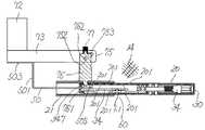
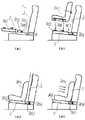
図1は本発明のチャイルドシートにおける車両の座席への装着の形態を示す側面図、図2は本発明の第1実施例における要部斜視図、図3は本発明の第1実施例における操作部が非操作状態の参考横断面図、図4は本発明の第1実施例における操作部が第一段階の参考横断面図、図5は本発明の第1実施例における操作部が第一段階の参考横断面図、図6は本発明の第1実施例における操作部が第二段階の参考横断面図、図7は本発明の第1実施例におけるフックが非ロック位置の参考縦断面図、図8は本発明の第1実施例におけるフックがロック位置の参考縦断面図、図9は本発明の第1実施例におけるロックアームが着脱制御範囲の参考横断面図、図10は本発明の第1実施例における操作部が未操作状態の要部斜視図、図11は本発明の第1実施例における操作部が第一段階の要部斜視図、図12は本発明におけるロックアームのロック部が非ロック位置の状態における縮みロック機構の拡大側面図、図13は本発明におけるロックアームのロック部が非ロック位置の状態における縮みロック機構の拡大断面図、図14は本発明におけるロックアームのロック部がロック位置の状態における縮みロック機構の拡大側面図、図15は本発明におけるロックアームのロック部がロック位置の状態における縮みロック機構の拡大断面図である。FIG. 1 is a side view showing a form of a child seat according to the present invention mounted on a seat of a vehicle, FIG. 2 is a perspective view of a main part in the first embodiment of the present invention, and FIG. Is a reference cross-sectional view in a non-operating state, FIG. 4 is a reference cross-sectional view of the operation unit in the first embodiment of the present invention, and FIG. 5 is a first step of the operation unit in the first embodiment of the present invention. FIG. 6 is a reference cross-sectional view of the operation unit in the first embodiment of the present invention in the second stage, and FIG. 7 is a reference vertical cross-sectional view of the hook in the first embodiment of the present invention in the unlocked position. 8 is a reference longitudinal sectional view of the hook in the first embodiment of the present invention in which the hook is in the locked position, FIG. 9 is a reference transverse sectional view of the locking arm in the first embodiment of the present invention in the attachment / detachment control range, and FIG. FIG. 11 is a perspective view of a main part of the first embodiment when the operation unit is not operated. FIG. 12 is an enlarged side view of a shrinkage lock mechanism in a state where the lock portion of the lock arm in the present invention is in the unlocked position, and FIG. 13 is a lock in the present invention. FIG. 14 is an enlarged cross-sectional view of the shrinkage lock mechanism when the lock portion of the arm is in the unlocked position, FIG. 14 is an enlarged side view of the shrinkage lock mechanism when the lock portion of the lock arm is in the lock position, and FIG. It is an expanded sectional view of a contraction lock mechanism in the state where the lock part of a lock arm is a lock position.
なお、以下の説明において、前後方向及び左右方向とは、チャイルドシートが設置される車両用シートに着座した者にとっての前後方向及び左右方向と合致する。In the following description, the front-rear direction and the left-right direction correspond to the front-rear direction and the left-right direction for a person seated on the vehicle seat on which the child seat is installed.
第1図の通り、本発明のチャイルドシート10の装着可能な車両の座席1は、座面2と、この座面の後部から上方に立設されたシートバック3を有し、前記座面2とシートバック3との接続部分近傍には、ISO−FIX方式のチャイルドシート連結用アンカとして、左右一対の取付受部4が設けられ、前記取付受部4は、座面2とシートバック3との接続部分近傍を左右方向に横切るように配設され、座席1に取り付けられている。As shown in FIG. 1, a vehicle seat 1 to which a child seat 10 of the present invention can be attached has a
そして前記チャイルドシート10は子供が座るための座面12と、座面12に着座した子供を拘束する拘束ベルトを有するシート体15と、前記シート体15と接続され、底面が車両の座席1の座面2と当接する様に構成されたベース体14とからなるチャイルドシート本体11と、前記ベース体14の後方下部から後方に向かって突出する左右一対のロックアーム20と、前記ロックアーム20の先端に配置され、前記取付受部4と係合可能なロック部30を有する。尚、シート体15とベース体14は一体に構成した構造でも良い。The child seat 10 is connected to a
図2に示す様に、前記左右一対のロックアーム20が前記ベース体14の底部位置に配置された左右一対のアームガイド21によって前後方向への移動が可能な状態でベース体14の内部に保持され、更に前記ベース体14内には前記左右一対のロックアーム20の伸縮動作を制御する制御機構40が配置され、前記制御機構40は前記左右一対のアームガイド21に固定された制御機構本体41と、前記制御機構40を操作する操作部42と、前記操作部42の操作によって前後方向に移動する制御機構リンク部材43と、前記制御機構リンク部材43を後方に付勢するバネ44と前記制御機構リンク部材43の先端位置と接続されたストッパーガイド45とを有する。As shown in FIG. 2, the pair of left and right lock
図3〜5に示す様に、前記ロックアーム20の前記制御機構本体41と対向する面には、前後方向に離間して複数の開口部201が形成され、前記制御機構本体41は、前記ロックアーム20の開口部201(凹みでも良い)に対して進退可能に構成されたストッパー46を有し、前記ストッパー46はバネ47によって前記開口部201の方向に付勢される。As shown in FIGS. 3 to 5, a plurality of
前記ストッパー46は、前記ロックアーム20の開口部201に対して、前側位置が略垂直に当接し、後側位置が傾斜面463によって当接可能に形成された先端係止部461と、前記ロックアーム20の開口部201に対して前側位置と後側位置が共に略垂直に当接可能に形成された第二係止部462を有する。The
更に、前記ストッパー46は、前記開口部201に対する進退方向と略垂直方向(上下方向)に突出する形状に形成されたガイド部465を有し、前記ガイド部465は、前記制御機構リンク部材43の先端位置と接続されたストッパーガイド45に形成されたガイド面と当接する様に構成される。Further, the
前記バネ44によって後方に付勢される前記制御機構リンク部材43は、前記操作部42の操作によって前方に移動する様に構成され、実施例1において前記操作部42のよる操作は、非操作状態と、第一段階までの操作状態と、第二段階までの操作状態からなり、前記ストッパー46のガイド部465と当接するガイド面は、前記ストッパーガイド45がバネによって後方に移動した状態の非操作ガイド面452と、前記操作部42の操作によって第一段階まで前方移動した第一移動ガイド面453と、前記操作部42の操作によって第二段階まで前方移動した第二移動ガイド面454を有する。The control
前記の操作部42の第一段階までの操作状態と、第二段階までの操作状態の切り替えは、前記操作部42に移動位置制御レバー(図示せず)を設け、前記操作部42の移動操作により前記第一段階の操作状態になった時点で、前記移動位置制御レバーがベース体14の一部と当接して前記操作部42の第二段階までの移動を制御する様に構成し、前記移動位置制御レバーを操作してベース体14との当接状態を解除する事によって前記操作部42の第二段階までの移動が可能になる様に構成する事が出来る。尚、前記操作部42の移動操作による前記第一段階の操作状態で、前記操作部42の第二段階までの移動を制御する構成は、本実施例に限定されず、既存の技術を応用する事ができる。尚、前記制御機構リンク部材43がバネ44によって前方に付勢されると共に、前記操作部42の操作によって後方に移動する様に構成しても良い。For switching between the operation state up to the first stage of the
図3に示す様に、上記制御機構40により、前記ストッパー46のガイド部465が当接するガイド面が、前記非操作ガイド面452の場合には、前記ロックアーム20の開口部201への突出距離が最大となり、前記ロックアーム20の開口部201に対して前記ストッパー46の第二係止部462が係止する事によって、前記ロックアーム20のベース体14に対する前後方向の移動が禁止される。As shown in FIG. 3, when the guide surface with which the
また、図4に示す様に、前記ストッパー46のガイド部465が当接するガイド面が第一移動ガイド面453の場合には、前記非操作ガイド面452よりも前記ロックアーム20からの距離が遠くなり、前記ロックアーム20の開口部201への突出するストッパー46の位置が先端係止部461の位置となる事によって、前記ロックアーム20のベース体14に対する後方向(伸び方向)の移動が禁止されるが、前記ロックアーム20のベース体14に対する前方向(縮み方向)の移動は禁止されず、図5に示す様に、前記ロックアーム20の前方向(縮み方向)の移動が可能になり、その際には前記ストッパー46の傾斜面463によってストッパー46が前記開口部201に対して進退を繰り返す様に構成されたラッチ構造となる。As shown in FIG. 4, when the guide surface with which the
また、図5に示す様に、前記ストッパー46のガイド部465が当接するガイド面が第二移動ガイド面454の場合には、前記第一移動ガイド面453よりも更に前記ロックアーム20からの距離が遠くなり、前記ロックアーム20の開口部201に対して、ストッパー46の前後両方の垂直面が非係止となる事によって、前記ロックアーム20のベース体14に対する前後方向の移動を制御する制御機構40が解除される。As shown in FIG. 5, when the guide surface with which the
尚、前記ストッパー46の前後両方の先端部に傾斜面を形成して(図示せず)、前記ストッパー46のガイド部465が当接するガイド面が第二移動ガイド面454の場合に、前記ロックアーム20の開口部201に対して、ストッパー46の前後両方に形成した傾斜面が当接する様に構成しても良く、その場合は前記ロックアーム20のベース体14に対する前後方向の移動が可能であるが、前記ロックアーム20の前後方向の移動時に前記ストッパー46が進退運動を繰り返す様になり、前記ロックアーム20の前後方向の移動時に段階的な操作感を得る事ができる。尚、本発明において、前記ロックアーム20の伸縮動作を制御する制御機構40は、本実施例に限定されず、既存のあらゆる伸縮動作の制御機構を利用する事ができる。When the guide surface with which the
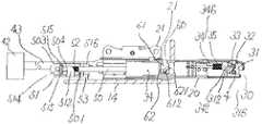
図7、図8に示す様に、本発明のチャイルドシートのロックアーム20の先端部に配置されたロック部30は、一端に車両の取付受部4を受入可能な受入口311が形成されたフック31を有し、前記フック31は前記ロックアーム20の左右の側壁間に配置された軸部32によって回動し、前記受入口311が後方に開口した状態の非ロック位置315と、前記受入口311がロックアーム20の下面によって閉鎖された状態のロック位置316との切り替えが可能な様に軸支され、前記軸部32の周囲に配置されたバネ33によって前記フック31は非ロック位置315の方向に付勢される様に構成される。As shown in FIGS. 7 and 8, the
更に前記ロック部30は、前記ロックアーム20の内部において前後方向に配置されたロックバー34と、前記ロックバー34を後方に付勢するバネ35を有し、前記ロックバー34は前記フック31が非ロック位置315の状態において、後方の先端部341が前記フック31と当接する第一のロックバー位置345を有する。The
更に前記ロックバー34は前記フック31がロック位置まで回動した時に先端部の上面342が前記フック31に形成された凹状係止部312と係合して前記フック31が非ロック位置315方向に回動する事を阻止する第二のロックバー位置346を有する。Further, when the
前記ロックアーム20の先端部に配置されたロック部30と前記取付受部4を係止させる際には、前記フック31の受入口311内に前記取付受部4を配置した状態で、前記バネ33の付勢力よりも大きな力でベース体14(チャイルドシート本体11)を後方に移動させる事によって、前記フック31が回動し、フック31に形成された凹状係止部312が前記ロックバー34の先端位置に移動する事により、バネ35の付勢力によって後方に付勢された前記ロックバー34の後方先端部341がフック31に形成された凹状係止部312内に移動し、前記ロックバー34の先端部の上面342と前記凹状係止部312の顎部313が係合して、前記ロック部30と前記取付受部4との係止状態が維持可能に構成される。When locking the
また、本実施例においては、図3〜図8に示す様に、前記ベース体14の底部位置に前後方向に配置された左右一対のロック解除リンク部材50を有し、前記ロック解除リンク部材50の後方部分は前記ロックアーム20内に配置され、前方部分には左右方向に略垂直に折り曲げた折曲腕部501と、この折曲腕部501を前方方向に略垂直に折り曲げた先端部503が形成され、前記折曲腕部501の略中央部には孔502が形成され、前記先端部503には前後方向に伸びる長孔504が形成され、このロック解除リンク部材50はアダプタ51を介して前方部分が前記制御機構リンク部材43と接続される。Further, in the present embodiment, as shown in FIGS. 3 to 8, the
前記アダプタ51は、左右方向の一方の位置に前記制御機構リンク部材43との固定部を有し、更に前記ロック解除リンク部材50を後方に付勢するためのバネ52を保持する手段と、前記ロック解除リンク部材50に対して前記アダプタ51の前後方向への相対的な移動を可能な状態で前記ロック解除リンク部材50を保持する手段と、前記ロック解除リンク部材50を前方に移動させるための移動手段を有する。The
ここで、前記ロック解除リンク部材50を後方に付勢するためのバネ52を保持する手段は、前記アダプタ51の前後略中央位置において左右他方の方向に突出する第一の腕部512と、その第一の腕部512の先端部に後方に向かって形成されたバネ受け部513よりなり、このバネ受け部513に前方端部が保持されたバネ52は後方端部が前記折曲腕部501の前面と当接して、ロック解除リンク部材50を後方に付勢する様に構成される。Here, the means for holding the
そして、前記ロック解除リンク部材50を前後方向に相対移動可能に保持する手段は、前記アダプタ51の前方位置において、左右他方の方向に突出して前記ロック解除リンク部材50の長孔504を貫通する様に配置され、その先端部には外れ止め用の顎部515が形成される第二の腕部514と、前記アダプタ51の後方位置において、左右他方の方向に突出し、更にその先端部から前方に向かって延在するピン状突起517を有する第三の腕部516を有し、前記ピン状突起517は、前記ロック解除リンク部材50の孔502を貫通する様に配置され、その先端部は、前記バネ受け部513と対向して配置され、バネ52の外れ止め機能を有する。The means for holding the unlocking
そして、前記ロック解除リンク部材50を前方に移動させるための移動手段は、第三の腕部516の前面が、前記折曲腕部501の後面と当接する事により実行される。The moving means for moving the lock
尚、前記折曲腕部501の後面は、ベース体14の底面から上方に延在して形成された位置決リブ53によって後方への移動位置が制限され、前記操作部42の非操作状態から第一段階までの操作状態において前記折曲腕部501の後面が前期位置決リブ53に突き当たる様に前記位置決リブ53を配置する事により、記操作部42の非操作状態から第一段階までの操作状態においては、第三の腕部516の前側面と前記折曲腕部501の後側との間が離間し、記操作部42を操作しても前記ロック解除リンク部材50が前後方向に移動せず、前記操作部42を第一段階までの操作状態から第二段階までの操作した際には、第三の腕部516の前面が前記折曲腕部501の後面と当接して、前記ロック解除リンク部材50が前方向に移動する様に構成される。The rear surface of the
上記構成において、前記ロックアーム20の伸縮位置は、図3〜図8で表示された、車両へのチャイルドシートの装着状態での使用範囲として設定された、前記前記ロックアーム20の複数の開口部201に対してストッパー46が係止可能な伸縮制御範囲22と、図9に示す様に、車両の前記取付受部4に対するロック部30の着脱のために設定された前記伸縮制御範囲22よりもベース体14から前記ロックアーム20が伸びた位置にある着脱制御範囲23とを有する様に構成される。In the above-described configuration, the expansion and contraction positions of the
そして、図10、図11に示す様に、前記ロック解除リンク部材50の後方部と、前記ロックバー34の前方部には、夫々係合部505、347が形成され、前記ロックアーム20が着脱制御範囲23にある時に、図10に示す前記操作部42の未操作状態から、図11に示す様に、前記操作部42の第一段階まで移動操作する事によりベース体14に対して前記ロック解除リンク部材50が前方向へ移動して前記ロック解除リンク部材50の係合部505と前記ロックバー34の係合部347が当接した状態となり、その状態では前記ロックバー34の移動が実施されないため、図8で示す様に、ロックバー34は第一のロックバー位置345の状態が維持され、更に、前記操作部42を第二段階まで移動操作する事によって、前記ロック解除リンク部材50の後方部に形成された係合部505の前方移動に伴い前記ロックバー34の前方部に形成された係合部347を含むロックバー34が前方に移動し、第二のロックバー位置346まで、または前記第二のロックバー位置346よりも前方向に移動する事により、図7に示す様に、前記ロックバー34の先端部の上面342と前記フック31の凹状係止部312との係合状態が解除され、前記ロック部30のフック31がバネ33の付勢力によって非ロック位置315に回動して前記ロック部30と取付受部4の係止状態が解除される様に構成される。10 and 11, engaging
尚、前記ロックアーム20が伸縮制御範囲22にある時には、前記操作部42を第二段階まで移動操作する事によりベース体14に対して前記ロック解除リンク部材50を前方向へ移動させても、前記ロック解除リンク部材50の係合部505と前記ロックバー34の係合部347は係合しないで離間した状態が維持される様に構成されるため、前記ロックバー34を前方に移動させる事が出来ず、前記ロック部30と取付受部4の係止状態を解除する事は出来ない。When the
従って、車両へのチャイルドシート10の装着状態から前記取付受部4に対する前記ロック部30の係合を解除する場合には、車両の座席1の座面2と当接するベース体14と、子供が座るための座面12部分を有するシート体15が接続された状態で、第一の操作として、前記操作部42を第二段階まで移動操作する事により、前記ロックアーム20のベース体14に対する前後方向の移動を可能とし、次に、第二の操作として、第一の操作を維持した状態でチャイルドシート本体11(ベース体14)を前方に移動させる事により前記ベース体14に対する前記ロックアーム20の伸縮位置を着脱制御範囲23まで移動する事により、ロック解除リンク部材50の係合部505と前記ロックバー34の係合部347が係合し、更にチャイルドシート本体11(ベース体14)を前方に移動させる事により、前記ロックバー34が前方に移動した第二のロックバー位置346になり、前記ロックバー34の先端部の上面342と前記フック31の凹状係止部312との係合状態が解除される事により、前記ロック部30のフック31がバネ33の付勢力によって非ロック位置315に回動し、前記ロック部30と取付受部4の係止状態が解除される。尚、前記ベース体14と、前記シート体15が分離可能な構成のチャイルドシートにおいては、前記ベース体14から前記シート体15を分離した状態で、前記取付受部4に対する前記ロック部30の係合を解除する操作を行なう事ができる様に構成しても良い。Therefore, when the engagement of the
尚、本発明において、車両へのチャイルドシート10の装着状態から前記取付受部4に対する前記ロック部30の係合を解除する手段は、上記の通り、第一の操作と第二の操作からなる複数の操作を行なわない限り、チャイルドシート10を車両の前記取付受部4から外す事ができないため、チャイルドシート10に拘束した子供による操作によって、保護者の意に反してチャイルドシート10が車両から外れてしまう事を防止できる。In the present invention, as described above, the means for releasing the engagement of the
更に、上記操作の1つに、チャイルドシート本体11(ベース体14)を前方に移動させる操作が含まれるため、子供がチャイルドシート10に着座した状態では子供の体重によってチャイルドシート10の底面と車両の座席1の座面2の摩擦抵抗が増大して操作が困難となるため、チャイルドシート10に着座した子供以外の操作者の誤操作によって、チャイルドシート10が車両から外れてしまう事を防止できる。Furthermore, since one of the above operations includes an operation of moving the child seat body 11 (base body 14) forward, when the child is seated on the child seat 10, the child seat 10 and the vehicle seat 1 are adjusted according to the weight of the child. Since the frictional resistance of the
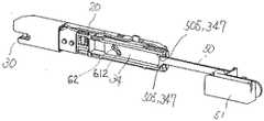
更に本発明のチャイルドシート10は、図7、図8、図12〜図15に示す様に、前記取付受部4に対する前記ロック部30の係合の解除と連動して作動する縮みロック機構60を有し、前記縮みロック機構60は作動時に前記チャイルドシート本体10に対するロックアーム20の伸縮制御範囲22への移動を禁止し、前記取付受部4に対する前記ロック部30の係合によって、前記縮みロック機構60が解除される様に構成されるため、前記ロックアーム20のロック部30は、フック31が非ロック位置315の状態においては常に前記ロックアーム20が着脱制御範囲23にある様に構成される。Furthermore, the child seat 10 of the present invention has a
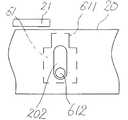
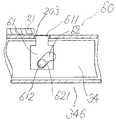
上記縮みロック機構60は、前記ロックアーム30が着脱制御範囲23の位置でロックアーム30から突出可能な突出部611を有するロック片61と、前記ロックバー34に形成され前側位置が低く後側位置が高く形成された傾斜面からなるガイド面621を有するロックガイド部62とを有し、前記ロック片61は左右方向に突出して形成されたガイドシャフト612を有し、左右何れか一方の前記ガイドシャフト612がロックアーム20の側面に上下方向に形成された長孔202内に配置される事により前記ロック片61の移動方向が上下方向に規制され、左右何れか他方の前記ガイドシャフト612は前記ロックガイド部62のガイド面621と当接する事により前記ガイドシャフト612と当接するガイド面621の高さによって前記ロック片61の上下位置が制御される様に構成され、更に前記ロックアーム20の前記ロック片61の配置位置には、前記ロック片61の突出部が通過可能な孔203が形成され、前記ロックアーム20から前記ロック片61の突出部が突出した状態においてアームガイド21(ベース体14に固定された部材であれば他の構成部材でも良い)と当接して前記ロックアーム20が伸縮制御範囲22に移動する事を防止する構成を有する。The
ここで、図7、図12、図13に示す、前記ロックアーム20のロック部30が非ロック位置315の状態においては、ロックバー34が前方に移動した第一のロックバー位置345となるため、前記ロック片61のガイドシャフト612は高い位置にある前記ロックガイド612の後側ガイド面と当接して前記ロック片61の突出部611が前記ロックアーム20から上方に突出して前記ロックアーム20の伸縮制御範囲22の方向の移動を禁止し、図8、図14、図15に示す、前記ロックアーム20のロック部30がロック位置316の状態においては、ロックバー20が後方に移動した第二のロックバー位置346となるため、前記ロック片61のガイドシャフトは低い位置にある前記ロックガイド部62の前側ガイド面621と当接して前記ロック片61の突出部611が前記ロックアーム20から上方から突出しない位置に保持され、前記ロックアーム20の伸縮制御範囲22の方向の移動が可能となる。Here, when the
よって、前記チャイルドシート10のロックアーム20のロック部30を、車両の前記取付受部4に係止する際には、前記ロック部30のフック31が非ロック位置315である限り、前記縮みロック機構60によってロックアーム20が伸縮制御範囲22に移動する事が防止されるため、前記ロックアーム20のロック部30を、確実に車両の前記取付受部4に係止する事が可能となる。尚、付属品としてダミーの取付受部(図示せず)を用意し、本発明のチャイルドシートを保管、収納する際には、まずロックアーム30が着脱制御範囲23の位置で前記ロック部30に前記ダミーの取付受部をロックさせる事により前記縮みロック機構60を解除し、次に前記操作部42を第一段階または第二段階までの操作した状態で、ベース体14への収納方向にロックアーム20を押し込む事により、車両への非装着状態でロックアーム20を収納した状態にする事ができる。Therefore, when the
以下、図面を参照して第2実施の形態について説明する。Hereinafter, a second embodiment will be described with reference to the drawings.
図1は本発明のチャイルドシートにおける車両の座席への装着の形態を示す側面図、図12は本発明におけるロックアームのロック部が非ロック位置の状態における縮みロック機構の拡大側面図、図13は本発明におけるロックアームのロック部が非ロック位置の状態における縮みロック機構の拡大断面図、図14は本発明におけるロックアームのロック部がロック位置の状態における縮みロック機構の拡大側面図、図15は本発明におけるロックアームのロック部がロック位置の状態における縮みロック機構の拡大断面図、図16は、本発明の第2実施例における操作部が非操作状態の参考横断面図、図17は本発明の第2実施例における操作部が操作状態(操作途中)の参考横断面図である。FIG. 1 is a side view showing a vehicle seat mounted on a child seat according to the present invention, FIG. 12 is an enlarged side view of a shrinkage lock mechanism in a state where a lock portion of a lock arm according to the present invention is in an unlocked position, and FIG. FIG. 14 is an enlarged cross-sectional view of the shrinkage lock mechanism in a state where the lock portion of the lock arm in the present invention is in the non-lock position, FIG. 14 is an enlarged side view of the shrinkage lock mechanism in a state in which the lock portion of the lock arm is in the lock position in FIG. FIG. 16 is an enlarged cross-sectional view of the shrinkage lock mechanism in a state where the lock portion of the lock arm in the present invention is in the lock position, FIG. 16 is a reference cross-sectional view in which the operation portion in the second embodiment of the present invention is in a non-operation state, and FIG. FIG. 9 is a reference cross-sectional view in which the operation unit according to the second embodiment of the present invention is in an operation state (during operation).
第1図の通り、本発明のチャイルドシートの装着可能な車両の座席は、座面2と、この座面の後部から上方に立設されたシートバック3を有し、前記座面とシートバック3との接続部分近傍には、ISO−FIX方式のチャイルドシート連結用アンカとして、左右一対の取付受部4が設けられ、各取付受部4は、座面2とシートバック3との接続部分近傍を左右方向に横切るように配設され、座席1に取り付けられている。As shown in FIG. 1, the seat of the vehicle to which the child seat of the present invention can be attached has a
そして前記チャイルドシート10は子供が座るための座面12と、座面12に着座した子供を拘束する拘束ベルトを有するシート体15と、前記シート体15と接続され、底面が車両の座席1の座面2と当接する様に構成されたベース体14とからなるチャイルドシート本体11と、前記ベース体14の後方下部から後方に向かって突出する左右一対のロックアーム20と、前記ロックアーム20の先端に配置され、前記取付受部4と係合可能なロック部30を有する。尚、シート体15とベース体14は一体に構成した構造でも良い。The child seat 10 is connected to a
図16、図17に示す様に、前記左右一対のロックアーム20は前記ベース体14の底部位置に配置された左右一対のアームガイド21によって前後方向への移動が可能な状態でベース体14の内部に保持され、更に前記ベース体14内には前記左右一対のロックアーム20の伸縮動作を制御する制御機構70が配置され、前記制御機構70は前記左右一対のアームガイド21に固定された制御機構本体71と、前記制御機構70を操作する操作部72と、前記操作部72の操作によって前後方向に移動する制御機構リンク部材73と、前記制御機構リンク部材73を後方に付勢するバネ(図示せず)と前記制御機構リンク部材73の先端位置に配置されたストッパーガイド75とを有する。As shown in FIGS. 16 and 17, the pair of left and right lock
前記ロックアーム20の前記制御機構本体71と対向する面には、前後方向に離間して複数の開口部201が形成され、前記制御機構本体71は、前記ロックアーム20の開口部201(凹みでも良い)に対して進退可能に構成されたストッパー76を有し、前記ストッパー76はバネ77によって前記開口部方向201に付勢される。A plurality of
前記ストッパー76は、前記ロックアーム20の開口部201に対して前側位置と後側位置が共に略垂直に当接可能に形成された係止部761を有する。The
更に、前記ストッパー76は、前記開口部201に対する進退方向と略垂直方向(上下方向)に突出する形状に形成されたガイド部762を有し、前記ガイド部762は、前記制御機構リンク部材73の先端部に配置されたストッパーガイド75に形成されたガイド面751と当接する様に構成される。Further, the
バネ74によって後方に付勢される前記制御機構リンク部材73は、前記操作部72の操作によって前方に移動する様に構成され、前記ストッパー76のガイド部762と当接するストッパーガイド75のガイド面は、バネによって前記ストッパーガイド75が後方に移動した状態の非操作ガイド面752と、前記操作部72の操作によって前記ストッパーガイド75が前方移動した状態の移動ガイド面753を有する。尚、前記制御機構リンク部材73はバネによって前方に付勢されると共に、前記操作部72の操作によって前記制御機構リンク部材73が後方に移動する様に構成しても良い。The control
前記ストッパー76のガイド部762が当接するガイド面751が、前記非操作ガイド面752の場合には、上記制御機構70により、前記ロックアーム20の開口部201から、前記ストッパー76の係止部761が突出し、前記ロックアーム20のベース体14に対する前後方向の移動が禁止される。When the guide surface 751 with which the
また、前記操作部72の操作によって前記ストッパー76のガイド部762が当接するガイド面751が移動ガイド面753の場合には、前記非操作ガイド面752よりも前記ロックアーム20からの距離が遠くなり、前記ロックアーム20の開口部201に対して、ストッパー76の前後両方の垂直面が非係止となる事によって、前記ロックアーム20のベース体14に対する前後方向の移動が可能となる。Further, when the guide surface 751 with which the
尚、前記ストッパー76の前後両方の先端部に傾斜面を形成して、前記ストッパー76のガイド部762が当接するガイド面751が移動ガイド面753の場合に、前記ロックアーム20の開口部201に対して、前記ストッパー76の前後両方の傾斜が当接する様に構成しても良く、その場合は前記ロックアーム20のベース体14に対する前後方向の移動が可能であるが、前記ロックアーム20の前後方向の移動時に前記ストッパー76が進退運動を繰り返す事によって、前記ロックアーム20の前後方向の移動時に段階的な操作感を得る事ができる。尚、本発明において、前記ロックアーム20の伸縮動作を制御する制御機構70は、本実施例に限定されず、既存のあらゆる伸縮動作の制御機構を利用する事ができる。It should be noted that inclined surfaces are formed at both front and rear ends of the
本発明のチャイルドシート10のロックアーム20の先端部に配置されたロック部30は、実施例1(図7、図8)と同様に、一端に車両の取付受部4を受入可能な受入口311が形成されたフック31を有し、前記フック31は前記ロックアーム20の左右の側壁間に配置された軸部32によって回動し、前記受入口311が後方に開口した状態の非ロック位置315と、前記受入口311がロックアーム20の下面によって閉鎖された状態のロック位置316との切り替えが可能な様に軸支され、前記軸部32の周囲に配置されたバネ33によって前記フック31は非ロック位置315の方向に付勢される様に構成される。The
更に前記ロック部30は、前記ロックアーム20の内部において前後方向に配置されたロックバー34と、前記ロックバー34を後方に付勢するバネ35を有し、前記ロックバー34は前記フック31が非ロック位置315の状態において、後方の先端部341が前記フック31と当接する第一のロックバー位置345を有する。The
更に前記ロックバー34は前記フック31がロック位置まで回動した時に先端部の上面342が前記フック31に形成された凹状係止部312と係合して前記フック31が非ロック位置315方向に回動する事を阻止する第二のロックバー位置346を有する。Further, when the
前記ロックアーム20の先端部に配置されたロック部30と前記取付受部4を係止させる際には、前記フック31の受入口311内に前記取付受部4を配置した状態で、前記バネ33の付勢力よりも大きな力でベース体14(チャイルドシート本体11)を後方に移動させる事によって、前記フック31が回動し、フック31に形成された凹状係止部312が前記ロックバー34の先端位置に移動する事により、バネ35の付勢力によって後方に付勢された前記ロックバー34の後方先端部341がフック31に形成された凹状係止部312内に移動し、前記ロックバー34の先端部の上面342と前記凹状係止部312の顎部313が係合して、前記ロック部30と前記取付受部4との係止状態が維持可能に構成される。When locking the
また、本実施例においては、図16、図17に示す様に、前後方向に配置された左右一対のロック解除リンク部材50を有し、前記ロック解除リンク部材50の後方部分は前記ロックアーム20内に配置され、前方部分には左右方向に略垂直に折り曲げた折曲腕部501と、この折曲腕部501を前方方向に略垂直に折り曲げた先端部503が形成され、前記先端部503は前記制御機構リンク部材73と固定される。Further, in this embodiment, as shown in FIGS. 16 and 17, it has a pair of left and right lock
前記操作部72を操作した際には、前記制御機構リンク部材73の前方への移動と連動して、前記ロック解除リンク部材50が前方向に移動する様に構成される。尚、この前記ロック解除リンク部材50の作動構造は、実施例1と同様に構成しても良く、また、他の既存の構成を利用しても良い。When the
上記構成において、実施例1と同様に、前記ロックアーム20の伸縮位置は、車両へのチャイルドシートの装着状態での使用範囲として設定された、前記前記ロックアーム20の複数の開口部201に対してストッパー46が係止可能な伸縮制御範囲22と、車両の前記取付受部4に対するロック部30の着脱のために設定された前記伸縮制御範囲22よりもベース体14から前記ロックアーム20が伸びた位置にある着脱制御範囲23とを有する様に構成される。(実施例1の図9参照)In the above-described configuration, as in the first embodiment, the expansion / contraction position of the
そして、実施例1(図10、図11)と同様に、前記ロック解除リンク部材50の後方部と、前記ロックバー34の前方部には、夫々係合部505、347が形成され、前記ロックアーム20が着脱制御範囲23にある時に、前記操作部72(図10、図11においては操作部51)を移動操作する事によりベース体14に対して前記ロック解除リンク部材50が前方向への移動し、前記ロック解除リンク部材50の係合部505と前記ロックバー34の係合部347が係合して前記ロックバー34を前方に移動させる様に構成され、前記ロックバー34が前記第二のロックバー位置346まで、または前記第二のロックバー位置346よりも前方向に移動する事によって、前記ロックバー34の先端部の上面342と前記フック31の凹状係止部312との係合状態が解除され、前記ロック部30のフック31がバネ33の付勢力によって非ロック位置315に回動して前記ロック部30と取付受部4の係止状態が解除される様に構成される。Similarly to the first embodiment (FIGS. 10 and 11), engaging
尚、前記ロックアーム20が伸縮制御範囲22にある時には、前記操作部72(図10、図11においては操作部51)を移動操作する事によりベース体14に対して前記ロック解除リンク部材50を前方向へ移動させても、前記ロック解除リンク部材50の係合部505と前記ロックバー34の係合部347は係合しないで離間した状態が維持される様に構成されるため、前記ロックバー34を前方に移動させる事が出来ず、前記ロック部30と取付受部4の係止状態を解除する事は出来ない。When the
従って、車両へのチャイルドシート10の装着状態から前記取付受部4に対する前記ロック部30の係合を解除する場合には、車両の座席1の座面2と当接するベース体14と、子供が座るための座面12部分を有するシート体15が接続された状態で、第一の操作として、図16、図17に示す、前記操作部72を移動操作する事により、前記ロックアーム20のベース体14に対する前後方向の移動を可能とし、次に、第二の操作として、第一の操作を維持した状態でチャイルドシート本体11(ベース体14)を前方に移動させる事により前記ベース体14に対する前記ロックアーム20の伸縮位置を着脱制御範囲23まで移動する事により、ロック解除リンク部材50の係合部505と前記ロックバー34の係合部347が係合し、更にチャイルドシート本体11(ベース体14)を前方に移動させる事により、前記ロックバー34が前方に移動した第二のロックバー位置346になり、前記ロックバー34の先端部の上面342と前記フック31の凹状係止部312との係合状態が解除される事により、前記ロック部30のフック31がバネ33の付勢力によって非ロック位置315に回動し、前記ロック部30と取付受部4の係止状態が解除される。尚、前記ベース体14と、前記シート体15が分離可能な構成のチャイルドシートにおいては、前記ベース体14から前記シート体15を分離した状態で、前記取付受部4に対する前記ロック部30の係合を解除する操作を行なう事ができる様に構成しても良い。Therefore, when the engagement of the
本発明においては、車両へのチャイルドシートの装着状態から前記取付受部に対する前記ロック部の係合を解除する手段は、上記の通り、第一の操作と第二の操作からなる複数の操作を行なわない限り、チャイルドシートを車両の前記取付受部から外す事ができないため、チャイルドシートに拘束した子供による操作によって、保護者の意に反してチャイルドシートが車両から外れてしまう事を防止できる。In the present invention, as described above, the means for releasing the engagement of the lock portion with respect to the attachment receiving portion when the child seat is attached to the vehicle performs a plurality of operations including the first operation and the second operation. Unless the child seat can be removed from the attachment receiving portion of the vehicle, it is possible to prevent the child seat from coming off the vehicle against the intention of the guardian by an operation by a child restrained by the child seat.
更に、上記操作の1つに、チャイルドシート本体11(ベース体14)を前方に移動させる操作が含まれるため、子供がチャイルドシート10に着座した状態では子供の体重によってチャイルドシート10の底面と車両の座席1の座面2の摩擦抵抗が増大して操作が困難となるため、チャイルドシート10に着座した子供以外の操作者の誤操作によって、チャイルドシート10が車両から外れてしまう事を防止できる。Furthermore, since one of the above operations includes an operation of moving the child seat body 11 (base body 14) forward, when the child is seated on the child seat 10, the child seat 10 and the bottom of the vehicle seat 1 depend on the weight of the child. Since the frictional resistance of the
更に本発明のチャイルドシート10は、実施例1と同様に、図7、図8、図12〜図15に示す様に、前記取付受部4に対する前記ロック部30の係合の解除と連動して作動する縮みロック機構60を有し、前記縮みロック機構60は作動時に前記チャイルドシート本体10に対するロックアーム20の伸縮制御範囲22への移動を禁止し、前記取付受部4に対する前記ロック部30の係合によって、前記縮みロック機構60が解除される様に構成されるため、前記ロックアーム20のロック部30は、フック31が非ロック位置315の状態においては常に前記ロックアーム20が着脱制御範囲23にある様に構成される。Furthermore, the child seat 10 of the present invention is interlocked with the release of the engagement of the
上記縮みロック機構60は、前記ロックアーム30が着脱制御範囲23の位置でロックアーム30から突出可能な突出部611を有するロック片61と、前記ロックバー34に形成され前側位置が低く後側位置が高く形成された傾斜面からなるガイド面621を有するロックガイド部62とを有し、前記ロック片61は左右方向に突出して形成されたガイドシャフト612を有し、左右何れか一方の前記ガイドシャフト612がロックアーム20の側面に上下方向に形成された長孔202内に配置される事により前記ロック片61の移動方向が上下方向に規制され、左右何れか他方の前記ガイドシャフト612は前記ロックガイド部62のガイド面621と当接する事により前記ガイドシャフト612と当接するガイド面621の高さによって前記ロック片61の上下位置が制御される様に構成され、更に前記ロックアーム20の前記ロック片61の配置位置には、前記ロック片61の突出部が通過可能な孔203が形成され、前記ロックアーム20から前記ロック片61の突出部が突出した状態においてアームガイド21(ベース体14に固定された部材であれば他の構成部材でも良い)と当接して前記ロックアーム20が伸縮制御範囲22に移動する事を防止する構成を有する。The
ここで、前記ロックアーム20のロック部30が非ロック位置315の状態においては、ロックバー34が前方に移動した第一のロックバー位置345となるため、前記ロック片61のガイドシャフト612は高い位置にある前記ロックガイド612の後側ガイド面と当接して前記ロック片61の突出部611が前記ロックアーム20から上方に突出して前記ロックアーム20の伸縮制御範囲22の方向の移動を禁止し、前記ロックアーム20のロック部30がロック位置316の状態においては、ロックバー20が後方に移動した第二のロックバー位置346となるため、前記ロック片61のガイドシャフトは低い位置にある前記ロックガイド部62の前側ガイド面621と当接して前記ロック片61の突出部611が前記ロックアーム20から上方から突出しない位置に保持され、前記ロックアーム20の伸縮制御範囲22の方向の移動が可能となる。Here, when the
よって、前記チャイルドシート10のロックアーム20のロック部30を、車両の前記取付受部4に係止する際には、前記ロック部30のフック31が非ロック位置315である限り、前記縮みロック機構60によってロックアーム20が伸縮制御範囲22に移動する事が防止されるため、前記ロックアーム20のロック部30を、確実に車両の前記取付受部4に係止する事が可能となる。尚、付属品としてダミーの取付受部(図示せず)を用意し、本発明のチャイルドシートを保管、収納する際には、まずロックアーム30が着脱制御範囲23の位置で前記ロック部30に前記ダミーの取付受部をロックさせる事により前記縮みロック機構60を解除し、次に前記操作部72を操作した状態で、ベース体14への収納方向にロックアーム20を押し込む事により、車両への非装着状態でロックアーム20を収納した状態にする事ができる。Therefore, when the
本発明のチャイルドシートは、アイソフィックス(ISO−FIX)方式の固定構造を有する車両の座席にチャイルドシートを固定するための構造として、産業上有効に利用できる。The child seat of the present invention can be effectively used industrially as a structure for fixing a child seat to a vehicle seat having an ISO-FIX type fixing structure.
1:座席、2:座面、3:シートバック、4:取付受部、10:チャイルドシート、11:チャイルドシート本体、12:座面、14:ベース体、15:シート体、20:ロックアーム、21:アームガイド、22:伸縮制御範囲、23:着脱制御範囲、30:ロック部、31:フック、32:軸部、33:バネ、34:ロックバー、35:バネ、40:制御機構、41:制御機構本体、42:操作部、43:制御機構リンク部材、44:バネ、45:ストッパーガイド、46:ストッパー、47:バネ、50:ロック解除リンク部材、51:アダプタ、52:バネ、53:位置決リブ、60:縮みロック機構、61:ロック片、62:ロックガイド部、70:制御機構、71:制御機構本体、72:操作部、73:制御機構リンク部材、75:ストッパーガイド、76:ストッパー、77:バネ、
201:開口部、202:長孔、203:孔、311:受入口、312:凹状係止部、313:顎部、315:非ロック位置、316:ロック位置、341:後方先端部、342:上面、345:第一のロックバー位置、346:第二のロックバー位置、347:係合部、452:非操作ガイド面、453:第一移動ガイド面、454:第二移動ガイド面、
461:先端係止部、462:第二係止部、463:傾斜面、465:ガイド部、752:非操作ガイド面、753:移動ガイド面、761:係止部、762:ガイド部、501:折曲腕部、502:孔、503:先端部、504:長孔、505:係合部、511:固定部、512:第一の腕部、513:バネ受け部、514:第二の腕部、515:顎部、516:第三の腕部、517:ピン状突起、611:突出部、612:ガイドシャフト、621:ガイド面、801:シート体、802:ベース体、803:ロックアーム、804:ロック部、805:フック、806:解除レバー、807:可動プレートDESCRIPTION OF SYMBOLS 1: Seat, 2: Seat surface, 3: Seat back, 4: Mounting receiving part, 10: Child seat, 11: Child seat main body, 12: Seat surface, 14: Base body, 15: Seat body, 20: Lock arm, 21 : Arm guide, 22: expansion / contraction control range, 23: attachment / detachment control range, 30: lock part, 31: hook, 32: shaft part, 33: spring, 34: lock bar, 35: spring, 40: control mechanism, 41: Control mechanism body, 42: operation unit, 43: control mechanism link member, 44: spring, 45: stopper guide, 46: stopper, 47: spring, 50: unlocking link member, 51: adapter, 52: spring, 53: Positioning rib, 60: Shrinkage lock mechanism, 61: Lock piece, 62: Lock guide part, 70: Control mechanism, 71: Control mechanism body, 72: Operation part, 73: Control mechanism link member, 7 : Stopper guide, 76: stopper, 77: spring,
201: opening, 202: long hole, 203: hole, 311: receiving port, 312: concave locking portion, 313: jaw, 315: unlocked position, 316: locked position, 341: rear tip, 342: Upper surface, 345: first lock bar position, 346: second lock bar position, 347: engagement portion, 452: non-operation guide surface, 453: first movement guide surface, 454: second movement guide surface,
461: tip locking portion, 462: second locking portion, 463: inclined surface, 465: guide portion, 752: non-operation guide surface, 753: moving guide surface, 761: locking portion, 762: guide portion, 501 : Bent arm part, 502: hole, 503: tip part, 504: long hole, 505: engagement part, 511: fixing part, 512: first arm part, 513: spring receiving part, 514: second arm part 515: jaw part, 516: third arm part, 517: pin-like protrusion, 611: protrusion part, 612: guide shaft, 621: guide surface, 801: sheet body, 802: base body, 803: lock arm, 804: Lock part, 805: Hook, 806: Release lever, 807: Movable plate
Claims (3)
Translated fromJapaneseチャイルドシート本体と、前記チャイルドシート本体の後方下部から後方に向かって突出する左右一対のロックアームと、
ロックアームの先端に配置されたロック部を有し、
車両へのチャイルドシートの装着状態において、前記左右一対のロックアームのロック部が夫々前記取付受部と係合する様に構成され、
前記取付受部に対する前記ロック部の係合を解除するロック解除機構と、前記チャイルドシート本体に対するロックアームの伸縮動作を制御する制御機構と、前記制御機構を操作する操作部と、を有するチャイルドシートにおいて、
前記ロックアームの伸縮位置は、車両へのチャイルドシートの装着状態での使用範囲からなる伸縮制御範囲と、車両の前記取付受部に対するロック部の着脱のために設定された前記伸縮制御範囲よりもチャイルドシート本体から前記ロックアームが伸びた位置にある着脱制御範囲と、を有する様に構成され、
車両へのチャイルドシートの装着状態から前記取付受部に対する前記ロック部の係合を解除する手段が、子供が座るための座面部分が分離されない状態で実施される、複数の操作手段によって実施可能に構成され、
車両へのチャイルドシートの装着状態から前記取付受部に対する前記ロック部の係合を解除する手段は、前記操作部の操作によって前記制御機構による前記ロックアームの伸縮動作の制御を解除する第一の操作手段と、前記操作部の操作によって前記ロックアームの伸縮動作の制御を解除した状態で前記チャイルドシート本体を前方に移動させる事により前記チャイルドシート本体に対する前記ロックアームの伸縮位置を伸縮制御範囲から着脱制御範囲まで移動させる第二の操作手段を有し、前記ロックアームの伸縮位置が着脱制御範囲にある状態で前記操作部が操作される事によって、前記ロック解除機構が作動する様に構成されることを特徴とするチャイルドシート。A child attached to a seat of a vehicle having a seat surface, a seat back erected upward from a rear portion of the seat surface, and an attachment receiving portion provided in the vicinity of a connection portion between the seat surface and the seat back. A child seat for sitting,
A child seat body, and a pair of left and right lock arms projecting rearward from the rear lower part of the child seat body;
It has a lock part arranged at the tip of the lock arm,
In the mounted state of the child seat on the vehicle, the lock portions of the pair of left and right lock arms are configured to engage with the attachment receiving portions, respectively.
In the child seat having a lock release mechanism that releases the engagement of the lock portion with respect to the attachment receiving portion, a control mechanism that controls expansion and contraction operation of the lock arm with respect to the child seat body, and an operation portion that operates the control mechanism.
The expansion / contraction position of the lock arm is an expansion / contraction control range including a use range in a state where the child seat is mounted on the vehicle, and the expansion / contraction control range set for attaching / detaching the lock portion to / from the attachment receiving portion of the vehicle. An attachment / detachment control range at a position where the lock arm extends from the main body, and
The means for releasing the engagement of the lock part with respect to the attachment receiving part from the child seat mounted state on the vehicle can be implemented by a plurality of operation means implemented in a state where the seat surface part for the child to sit is not separated. Configured,
The means for releasing the engagement of the lock part with respect to the attachment receiving part from the child seat mounted state on the vehicle is a first operation for releasing the control of the expansion / contraction operation of the lock arm by the control mechanism by the operation of the operation part. And an extension control range of the lock arm with respect to the child seat body by moving the child seat body forward in a state where the control of the extension / retraction operation of the lock arm is released by operation of the operating unit having a second operating means for moving up, by which the operating portion is operated in a state where expansion and contraction position of the locking arm is in detachable control range, the Rukotothe unlocking mechanism is configured so as to operate Characterized child seat.
前記取付受部に対する前記ロック部の係合によって、前記縮みロック機構が解除される様に構成されることを特徴とする請求項1または2記載のチャイルドシート。A shrinkage lock mechanism that operates in conjunction with the release of the engagement of the lock portion with respect to the attachment receiving portion, the shrinkage lock mechanism prohibits movement of the lock arm to the extension control range of the child seat body during operation;
The child seat according to claim 1or 2 , wherein the contraction lock mechanism is released by engagement of the lock portion with the attachment receiving portion.
Priority Applications (4)
| Application Number | Priority Date | Filing Date | Title |
|---|---|---|---|
| JP2011158330AJP5814672B2 (en) | 2011-07-19 | 2011-07-19 | child seat |
| EP12814448.2AEP2735474B1 (en) | 2011-07-19 | 2012-06-21 | Child seat |
| CN201280033675.5ACN103796872B (en) | 2011-07-19 | 2012-06-21 | Children's seat |
| PCT/JP2012/004018WO2013011630A1 (en) | 2011-07-19 | 2012-06-21 | Child seat |
Applications Claiming Priority (1)
| Application Number | Priority Date | Filing Date | Title |
|---|---|---|---|
| JP2011158330AJP5814672B2 (en) | 2011-07-19 | 2011-07-19 | child seat |
Publications (2)
| Publication Number | Publication Date |
|---|---|
| JP2013023032A JP2013023032A (en) | 2013-02-04 |
| JP5814672B2true JP5814672B2 (en) | 2015-11-17 |
Family
ID=47557833
Family Applications (1)
| Application Number | Title | Priority Date | Filing Date |
|---|---|---|---|
| JP2011158330AActiveJP5814672B2 (en) | 2011-07-19 | 2011-07-19 | child seat |
Country Status (4)
| Country | Link |
|---|---|
| EP (1) | EP2735474B1 (en) |
| JP (1) | JP5814672B2 (en) |
| CN (1) | CN103796872B (en) |
| WO (1) | WO2013011630A1 (en) |
Families Citing this family (18)
| Publication number | Priority date | Publication date | Assignee | Title |
|---|---|---|---|---|
| US9227537B2 (en)* | 2013-09-27 | 2016-01-05 | Wonderland Nurserygoods Company Limited | Seat buffering device and vehicle safety seat having the same |
| WO2015151181A1 (en)* | 2014-03-31 | 2015-10-08 | コンビ株式会社 | Child seat |
| CN104553906B (en)* | 2014-12-25 | 2017-01-11 | 好孩子儿童用品有限公司 | Juvenile automobile safety seat |
| CN104590067B (en)* | 2015-01-14 | 2016-09-07 | 好孩子儿童用品有限公司 | The connector of a kind of child safety seat and child safety seat |
| CN106256597B (en)* | 2015-06-17 | 2018-04-17 | 浙江感恩科技股份有限公司 | A kind of child safety seat |
| WO2016207451A1 (en)* | 2015-06-24 | 2016-12-29 | Lagunar Herranz José | Securing device for securing objects in a vehicle |
| CN105015372B (en)* | 2015-07-24 | 2017-08-04 | 杭州龙生儿童用品有限公司 | A kind of device for installing and adjusting of automobile children safety chair |
| JP6663730B2 (en)* | 2016-01-26 | 2020-03-13 | ニューウェルブランズ・ジャパン合同会社 | ISOFIX child seat |
| CN107284311B (en)* | 2016-03-30 | 2020-06-23 | 上海沃雨电子科技有限公司 | Folding electric child safety seat |
| CN107264348B (en)* | 2016-04-07 | 2020-03-31 | 上海沃雨电子科技有限公司 | Folding manual child safety seat |
| EP3448716B1 (en)* | 2016-04-29 | 2021-04-14 | Holmbergs Safety System Holding AB | A connecting bar for a child restraint system |
| CA2997481C (en)* | 2017-03-03 | 2019-05-07 | Wonderland Switzerland Ag | Support base for a child safety seat |
| CN107672492A (en)* | 2017-10-31 | 2018-02-09 | 安徽羽贝安全科技有限公司 | A kind of child safety seat two level tripper |
| CN107985142B (en)* | 2017-12-07 | 2024-02-27 | 宁波宝贝第一母婴用品有限公司 | ISOFIX connector and child safety seat |
| US10906436B2 (en)* | 2018-02-21 | 2021-02-02 | Artsana Usa, Inc. | Quick release apparatus for a latch connector on a booster seat |
| JP7094819B2 (en)* | 2018-07-31 | 2022-07-04 | 株式会社カーメイト | ISOFIX child seat |
| CN110758192A (en)* | 2019-11-11 | 2020-02-07 | 苏州纪宝儿童用品有限公司 | Double-side synchronous opening and closing type fixing lock catch on child safety seat |
| CN115972998B (en)* | 2023-01-17 | 2025-08-22 | 宁波宝贝第一母婴用品有限公司 | A safety seat |
Family Cites Families (8)
| Publication number | Priority date | Publication date | Assignee | Title |
|---|---|---|---|---|
| JP2001122004A (en)* | 1999-10-27 | 2001-05-08 | Nissan Shatai Co Ltd | Seat for vehicle |
| JP4439647B2 (en)* | 1999-12-20 | 2010-03-24 | コンビ株式会社 | Child seat fixing device |
| JP2001180347A (en) | 1999-12-28 | 2001-07-03 | Car Mate Mfg Co Ltd | child seat |
| JP2001180346A (en)* | 1999-12-28 | 2001-07-03 | Car Mate Mfg Co Ltd | child seat |
| JP2001206117A (en)* | 2000-01-27 | 2001-07-31 | Honda Motor Co Ltd | Attachment for infant seat |
| EP1849649B1 (en)* | 2006-04-26 | 2012-04-11 | SABELT S.p.A. | Device for fastening a child seat to a fixed striker in a motor vehicle |
| EP1970247A1 (en)* | 2007-03-15 | 2008-09-17 | Team-Tex | Device for mounting a child seat in a car and a child seat |
| JP5157262B2 (en)* | 2007-05-30 | 2013-03-06 | タカタ株式会社 | child seat |
- 2011
- 2011-07-19JPJP2011158330Apatent/JP5814672B2/enactiveActive
- 2012
- 2012-06-21WOPCT/JP2012/004018patent/WO2013011630A1/enactiveApplication Filing
- 2012-06-21EPEP12814448.2Apatent/EP2735474B1/ennot_activeNot-in-force
- 2012-06-21CNCN201280033675.5Apatent/CN103796872B/ennot_activeExpired - Fee Related
Also Published As
| Publication number | Publication date |
|---|---|
| WO2013011630A1 (en) | 2013-01-24 |
| CN103796872A (en) | 2014-05-14 |
| JP2013023032A (en) | 2013-02-04 |
| CN103796872B (en) | 2017-04-05 |
| EP2735474A1 (en) | 2014-05-28 |
| EP2735474B1 (en) | 2018-11-14 |
| EP2735474A4 (en) | 2015-01-21 |
Similar Documents
| Publication | Publication Date | Title |
|---|---|---|
| JP5814672B2 (en) | child seat | |
| US7040702B2 (en) | Tip-up vehicle seat | |
| JP5169146B2 (en) | Vehicle seat device | |
| EP2210770B1 (en) | Vehicle seat | |
| US8070228B2 (en) | Child vehicle seat | |
| US8882196B2 (en) | Child safety seat | |
| EP2067917B1 (en) | Lock device for a vehicle | |
| US8297678B2 (en) | Retractable seat for vehicle | |
| CN108621880A (en) | Child safety seat | |
| JP2009067309A (en) | Vehicle seat | |
| EP3600954B1 (en) | Adjustable connecting bar for a child restraint system | |
| KR20060041979A (en) | Lock mechanism of the child seat and child seat fixing device of the stroller | |
| CN107107789B (en) | Adjustable connecting rod for child vehicle seat | |
| JP2007055433A (en) | Child seat | |
| JP2008024110A (en) | Automotive seat slide device | |
| JP4946039B2 (en) | child seat | |
| JP2007230333A (en) | Seat slide device | |
| JP5307501B2 (en) | Retractable vehicle seat | |
| JP2023082976A (en) | seat | |
| JP5601907B2 (en) | Seat unlock lever device | |
| CN114683976B (en) | Child safety seats | |
| JP2011131675A (en) | Seat for vehicle | |
| JP2006008010A (en) | Vehicle seat slide device | |
| JP5601187B2 (en) | Sliding device for vehicle seat | |
| JP5747747B2 (en) | Sliding device for vehicle seat |
Legal Events
| Date | Code | Title | Description |
|---|---|---|---|
| A621 | Written request for application examination | Free format text:JAPANESE INTERMEDIATE CODE: A621 Effective date:20140526 | |
| A131 | Notification of reasons for refusal | Free format text:JAPANESE INTERMEDIATE CODE: A131 Effective date:20150526 | |
| A521 | Request for written amendment filed | Free format text:JAPANESE INTERMEDIATE CODE: A523 Effective date:20150717 | |
| TRDD | Decision of grant or rejection written | ||
| A01 | Written decision to grant a patent or to grant a registration (utility model) | Free format text:JAPANESE INTERMEDIATE CODE: A01 Effective date:20150901 | |
| A61 | First payment of annual fees (during grant procedure) | Free format text:JAPANESE INTERMEDIATE CODE: A61 Effective date:20150918 | |
| R150 | Certificate of patent or registration of utility model | Ref document number:5814672 Country of ref document:JP Free format text:JAPANESE INTERMEDIATE CODE: R150 | |
| R250 | Receipt of annual fees | Free format text:JAPANESE INTERMEDIATE CODE: R250 | |
| R250 | Receipt of annual fees | Free format text:JAPANESE INTERMEDIATE CODE: R250 | |
| R250 | Receipt of annual fees | Free format text:JAPANESE INTERMEDIATE CODE: R250 | |
| R250 | Receipt of annual fees | Free format text:JAPANESE INTERMEDIATE CODE: R250 | |
| R250 | Receipt of annual fees | Free format text:JAPANESE INTERMEDIATE CODE: R250 | |
| R250 | Receipt of annual fees | Free format text:JAPANESE INTERMEDIATE CODE: R250 | |
| R250 | Receipt of annual fees | Free format text:JAPANESE INTERMEDIATE CODE: R250 | |
| R250 | Receipt of annual fees | Free format text:JAPANESE INTERMEDIATE CODE: R250 |