JP5812759B2 - Work vehicle - Google Patents
Work vehicleDownload PDFInfo
- Publication number
- JP5812759B2 JP5812759B2JP2011180915AJP2011180915AJP5812759B2JP 5812759 B2JP5812759 B2JP 5812759B2JP 2011180915 AJP2011180915 AJP 2011180915AJP 2011180915 AJP2011180915 AJP 2011180915AJP 5812759 B2JP5812759 B2JP 5812759B2
- Authority
- JP
- Japan
- Prior art keywords
- frame
- mount
- vibration
- supported
- drive unit
- Prior art date
- Legal status (The legal status is an assumption and is not a legal conclusion. Google has not performed a legal analysis and makes no representation as to the accuracy of the status listed.)
- Active
Links
Images


Classifications
- B—PERFORMING OPERATIONS; TRANSPORTING
- B60—VEHICLES IN GENERAL
- B60K—ARRANGEMENT OR MOUNTING OF PROPULSION UNITS OR OF TRANSMISSIONS IN VEHICLES; ARRANGEMENT OR MOUNTING OF PLURAL DIVERSE PRIME-MOVERS IN VEHICLES; AUXILIARY DRIVES FOR VEHICLES; INSTRUMENTATION OR DASHBOARDS FOR VEHICLES; ARRANGEMENTS IN CONNECTION WITH COOLING, AIR INTAKE, GAS EXHAUST OR FUEL SUPPLY OF PROPULSION UNITS IN VEHICLES
- B60K5/00—Arrangement or mounting of internal-combustion or jet-propulsion units
- B60K5/02—Arrangement or mounting of internal-combustion or jet-propulsion units with the engine main axis, e.g. crankshaft axis, substantially in or parallel to the longitudinal centre line of the vehicle
- B—PERFORMING OPERATIONS; TRANSPORTING
- B60—VEHICLES IN GENERAL
- B60K—ARRANGEMENT OR MOUNTING OF PROPULSION UNITS OR OF TRANSMISSIONS IN VEHICLES; ARRANGEMENT OR MOUNTING OF PLURAL DIVERSE PRIME-MOVERS IN VEHICLES; AUXILIARY DRIVES FOR VEHICLES; INSTRUMENTATION OR DASHBOARDS FOR VEHICLES; ARRANGEMENTS IN CONNECTION WITH COOLING, AIR INTAKE, GAS EXHAUST OR FUEL SUPPLY OF PROPULSION UNITS IN VEHICLES
- B60K17/00—Arrangement or mounting of transmissions in vehicles
- B60K17/34—Arrangement or mounting of transmissions in vehicles for driving both front and rear wheels, e.g. four wheel drive vehicles
- B—PERFORMING OPERATIONS; TRANSPORTING
- B60—VEHICLES IN GENERAL
- B60K—ARRANGEMENT OR MOUNTING OF PROPULSION UNITS OR OF TRANSMISSIONS IN VEHICLES; ARRANGEMENT OR MOUNTING OF PLURAL DIVERSE PRIME-MOVERS IN VEHICLES; AUXILIARY DRIVES FOR VEHICLES; INSTRUMENTATION OR DASHBOARDS FOR VEHICLES; ARRANGEMENTS IN CONNECTION WITH COOLING, AIR INTAKE, GAS EXHAUST OR FUEL SUPPLY OF PROPULSION UNITS IN VEHICLES
- B60K5/00—Arrangement or mounting of internal-combustion or jet-propulsion units
- B60K5/12—Arrangement of engine supports
- B60K5/1208—Resilient supports
- B60K5/1216—Resilient supports characterised by the location of the supports relative to the motor or to each other
- B—PERFORMING OPERATIONS; TRANSPORTING
- B60—VEHICLES IN GENERAL
- B60K—ARRANGEMENT OR MOUNTING OF PROPULSION UNITS OR OF TRANSMISSIONS IN VEHICLES; ARRANGEMENT OR MOUNTING OF PLURAL DIVERSE PRIME-MOVERS IN VEHICLES; AUXILIARY DRIVES FOR VEHICLES; INSTRUMENTATION OR DASHBOARDS FOR VEHICLES; ARRANGEMENTS IN CONNECTION WITH COOLING, AIR INTAKE, GAS EXHAUST OR FUEL SUPPLY OF PROPULSION UNITS IN VEHICLES
- B60K13/00—Arrangement in connection with combustion air intake or gas exhaust of propulsion units
- B60K13/04—Arrangement in connection with combustion air intake or gas exhaust of propulsion units concerning exhaust
- B—PERFORMING OPERATIONS; TRANSPORTING
- B60—VEHICLES IN GENERAL
- B60K—ARRANGEMENT OR MOUNTING OF PROPULSION UNITS OR OF TRANSMISSIONS IN VEHICLES; ARRANGEMENT OR MOUNTING OF PLURAL DIVERSE PRIME-MOVERS IN VEHICLES; AUXILIARY DRIVES FOR VEHICLES; INSTRUMENTATION OR DASHBOARDS FOR VEHICLES; ARRANGEMENTS IN CONNECTION WITH COOLING, AIR INTAKE, GAS EXHAUST OR FUEL SUPPLY OF PROPULSION UNITS IN VEHICLES
- B60K17/00—Arrangement or mounting of transmissions in vehicles
- B60K17/04—Arrangement or mounting of transmissions in vehicles characterised by arrangement, location or kind of gearing
- B60K17/10—Arrangement or mounting of transmissions in vehicles characterised by arrangement, location or kind of gearing of fluid gearing
- B—PERFORMING OPERATIONS; TRANSPORTING
- B60—VEHICLES IN GENERAL
- B60K—ARRANGEMENT OR MOUNTING OF PROPULSION UNITS OR OF TRANSMISSIONS IN VEHICLES; ARRANGEMENT OR MOUNTING OF PLURAL DIVERSE PRIME-MOVERS IN VEHICLES; AUXILIARY DRIVES FOR VEHICLES; INSTRUMENTATION OR DASHBOARDS FOR VEHICLES; ARRANGEMENTS IN CONNECTION WITH COOLING, AIR INTAKE, GAS EXHAUST OR FUEL SUPPLY OF PROPULSION UNITS IN VEHICLES
- B60K17/00—Arrangement or mounting of transmissions in vehicles
- B60K17/22—Arrangement or mounting of transmissions in vehicles characterised by arrangement, location, or type of main drive shafting, e.g. cardan shaft
- B—PERFORMING OPERATIONS; TRANSPORTING
- B60—VEHICLES IN GENERAL
- B60Y—INDEXING SCHEME RELATING TO ASPECTS CROSS-CUTTING VEHICLE TECHNOLOGY
- B60Y2200/00—Type of vehicle
- B60Y2200/10—Road Vehicles
- B60Y2200/14—Trucks; Load vehicles, Busses
- B60Y2200/141—Light trucks
Landscapes
- Engineering & Computer Science (AREA)
- Chemical & Material Sciences (AREA)
- Combustion & Propulsion (AREA)
- Transportation (AREA)
- Mechanical Engineering (AREA)
- Body Structure For Vehicles (AREA)
- Arrangement Or Mounting Of Propulsion Units For Vehicles (AREA)
- Vehicle Body Suspensions (AREA)
Description
Translated fromJapanese本発明は、走行機体の後部位置に駆動部が配置されている作業車に関し、詳しくは、駆動部を支持する構成に関する。 The present invention relates to a work vehicle in which a drive unit is disposed at a rear position of a traveling machine body, and more particularly to a configuration that supports the drive unit.
作業車において駆動部を支持する構成として特許文献1には、車体フレームが左右一対のアッパーパイプと、左右一対のロアーパイプとを備えて構成され、エンジンと変速装置とで成る駆動部(文献では、エンジンユニット)の底部が下部エンジンマウントにより防振的にロアーパイプに支持され、この駆動部のエンジンの上部が、上部エンジンマウントにより、アッパーパイプの一方に防振的に支持された構成が記載されている。 In
この特許文献1では、駆動部の下部を下側のフレームに防振的に支持し、駆動部の上部を下側のフレームに防振的に支持することで、不整地等を走行する場合にも駆動部が大きく振動する現象を抑制し、ジャンプ着地や急なコーナリング、急加速において駆動部の上部が大きく変位する不都合を抑制するように構成されている。 In
作業車に備えられる駆動部としては、エンジン、ミッションケース、無段変速装置等が考えられ、これらは重量物である。また、この駆動部は振動が抑制される状態で、しかも、大きく変位することなく機体フレームに支持されることが望まれる。 As the drive unit provided in the work vehicle, an engine, a transmission case, a continuously variable transmission, and the like can be considered, and these are heavy objects. In addition, it is desirable that the drive unit be supported by the body frame without being greatly displaced in a state where vibration is suppressed.
このような要望に対して特許文献1に記載されるように機体フレームの下部構造に対して駆動部の下部を支持し、機体フレームの上部構造に対して駆動部の上部を支持する構造では、駆動部の大きな変位を抑制できるものとなる。 In response to such a request, as described in
しかしながら、作業車のように比較的大型の駆動部をフレームに支持するために、特許文献1に記載されるように、機体フレームを構成する左右一対のアッパーパイプの一方に駆動部の上部を支持するものでは、駆動部のうち、アッパーパイプの他方に対応する側がの変位が許されることになり、駆動部の姿勢が不安定になり易く改善の余地がある。 However, in order to support a relatively large drive unit on a frame like a work vehicle, as described in
特に、機体フレームが左右一対の下部フレームを備えた構成で、左右一対の下部フレームの左右方向での間隔が狭いものでは、駆動部の底部の両側部をマウントにより下部フレームに支持した構成でも、左右のマウントの間隔が短くなり、駆動部の上部の横方向への振動を抑制し難いものとなり、このような点にも改善の余地がある。 In particular, if the fuselage frame is provided with a pair of left and right lower frames, and the pair of left and right lower frames is narrow in the left-right direction, the structure in which both sides of the bottom of the drive unit are supported by the lower frame by mounting, The distance between the left and right mounts is shortened, and it becomes difficult to suppress the vibration in the lateral direction of the upper part of the drive unit. There is room for improvement in this respect as well.
本発明の目的は、機体フレームに支持される駆動部の上部の横揺れを良好に抑制する作業車を合理的に構成する点にある。 The objective of this invention exists in the point which comprises rationally the work vehicle which suppresses the rolling of the upper part of the drive part supported by a body frame favorably.
本発明のうち第1発明の特徴は、走行機体の後部位置に駆動部が配置されている作業車であって、
前記駆動部が、エンジンと、ミッションケースと、を連結して構成され、
前記走行機体の機体フレームが、前後に伸びる下部フレームと、前後に伸びる左右一対の上部フレームとを有し、
前記駆動部の左右両側の下部が、前記下部フレームに対して下部防振マウントにより支持され、
前記ミッションケースの上部が、左右の前記上部フレームに架け渡された横フレームの中間部であって、上面視で前記ミッションケースと重複する位置に備えられている上部防振マウントにより支持され、
前記下部防振マウントが第1軸芯周りに防振可能に構成され、
前記上部防振マウントが第2軸芯周りに防振可能に構成され、
前記第1軸芯と前記第2軸芯とが平面視で交差するように、前記下部防振マウントと前記上部防振マウントとが配置されている点にある。A feature ofthe first invention of the present invention is a work vehicle in which a drive unit is disposed at a rear position of the traveling machine body,
The drive unit is configured by connecting an engine and a mission case,
The aircraft frame of the traveling aircraft has a lower frame extending in the front-rear direction and a pair of left and right upper frames extending in the front-rear direction,
Lower portions on both the left and right sides of the drive unit are supported by a lower vibration isolation mount with respect to the lower frame,
The upper part of the mission case is an intermediate part of a horizontal frame spanned between the left and right upper frames, and is supported by an upper vibration isolation mount provided at a position overlapping the mission case in a top view,
The lower vibration isolation mount is configured to be capable of vibration isolation around the first axis.
The upper vibration-proof mount is configured to be capable of vibration-proof around the second axis,
The lower anti-vibration mount and the upper anti-vibration mount are arranged so that the first axis and the second axis intersect in plan view .
この構成によると、下部フレームの横方向での間隔が短く、この下部フレームに下部防振マウントにより駆動部を支持した場合のように、左右の下部防振マウント間隔が短くても、横フレームの中間部に上部防振マウントにより駆動部の上部を支持することで、この駆動部の上部の左右方向への振動を良好に抑制できる。また、横フレームは、左右の上部フレームに架け渡されているので、駆動部の横幅方向での中央位置に上部防振マウントを配置することも可能となり、駆動部が振動する場合にも横方向の振幅に偏りのないものにできる。
その結果、機体フレームに支持される駆動部の上部の横揺れを良好に抑制する作業車が構成された。
さらに、駆動部としてのエンジンとミッションケースとが、下部の前後位置の防振マウントにより重量を受け止める状態で支持されると共に、上部の防振マウントにより横方向への振動を抑制する状態で走行機体に支持されるものとなる。According to this configuration, the horizontal distance between the lower frames is short, and even if the left and right lower anti-vibration mounts are short as in the case where the drive unit is supported by the lower anti-vibration mounts on the lower frame, By supporting the upper part of the drive unit by the upper vibration-proof mount at the intermediate part, it is possible to satisfactorily suppress vibration in the left-right direction of the upper part of the drive unit. In addition, since the horizontal frame spans the left and right upper frames, it is possible to place the upper anti-vibration mount at the center position in the lateral width direction of the drive unit, and even when the drive unit vibrates in the lateral direction Can be made to have no bias in the amplitude.
As a result, a work vehicle that satisfactorily suppress the rolling of the upper portion of the drive unit supported by the machine frame is configured.
Further, the engine and the transmission case as a drive unit are supported in a state where the weight is received by the vibration isolating mount at the lower front and rear positions, and the traveling aircraft body is suppressed in the lateral direction by the upper vibration isolating mount. Will be supported.
本発明のうち第2発明の特徴は、走行機体の後部位置に駆動部が配置されている作業車であって、A feature of the second invention of the present invention is a work vehicle in which a drive unit is disposed at a rear position of the traveling machine body,
前記駆動部が、ミッションケースのみで構成され、The drive unit is composed only of a mission case,
前記走行機体の機体フレームが、前後に伸びる下部フレームと、前後に伸びる左右一対の上部フレームとを有し、The aircraft frame of the traveling aircraft has a lower frame extending in the front-rear direction and a pair of left and right upper frames extending in the front-rear direction,
前記ミッションケースの左右両側の下部が、前記下部フレームに対して下部防振マウントにより支持され、Lower portions of the left and right sides of the mission case are supported by a lower vibration isolation mount with respect to the lower frame,
前記ミッションケースの上部が、左右の前記上部フレームに架け渡された横フレームの中間部であって、上面視で前記ミッションケースと重複する位置に備えられている上部防振マウントにより支持され、The upper part of the mission case is an intermediate part of a horizontal frame spanned between the left and right upper frames, and is supported by an upper vibration isolation mount provided at a position overlapping the mission case in a top view,
前記下部防振マウントが第1軸芯周りに防振可能に構成され、The lower vibration isolation mount is configured to be capable of vibration isolation around the first axis.
前記上部防振マウントが第2軸芯周りに防振可能に構成され、The upper vibration-proof mount is configured to be capable of vibration-proof around the second axis,
前記第1軸芯と前記第2軸芯とが平面視で交差するように、前記下部防振マウントと前記上部防振マウントとが配置されている点にある。The lower anti-vibration mount and the upper anti-vibration mount are arranged so that the first axis and the second axis intersect in plan view.
この構成によると、下部フレームの横方向での間隔が短く、この下部フレームに下部防振マウントにより駆動部を支持した場合のように、左右の下部防振マウント間隔が短くても、横フレームの中間部に上部防振マウントにより駆動部の上部を支持することで、この駆動部の上部の左右方向への振動を良好に抑制できる。また、横フレームは、左右の上部フレームに架け渡されているので、駆動部の横幅方向での中央位置に上部防振マウントを配置することも可能となり、駆動部が振動する場合にも横方向の振幅に偏りのないものにできる。According to this configuration, the horizontal distance between the lower frames is short, and even if the left and right lower anti-vibration mounts are short as in the case where the drive unit is supported by the lower anti-vibration mounts on the lower frame, By supporting the upper part of the drive unit by the upper vibration-proof mount at the intermediate part, it is possible to satisfactorily suppress vibration in the left-right direction of the upper part of the drive unit. In addition, since the horizontal frame spans the left and right upper frames, it is possible to place the upper anti-vibration mount at the center position in the lateral width direction of the drive unit, and even when the drive unit vibrates in the lateral direction Can be made to have no bias in the amplitude.
その結果、機体フレームに支持される駆動部の上部の横揺れを良好に抑制する作業車が構成された。As a result, a work vehicle that satisfactorily suppress the rolling of the upper portion of the drive unit supported by the machine frame is configured.
さらに、駆動部としてのミッションケースが、下部の防振マウントにより重量を受け止める状態で支持されると共に、上部の防振マウントにより横方向への振動を抑制する状態で走行機体に支持されるものとなる。Furthermore, the transmission case as a drive unit is supported by the lower vibration-proof mount in a state where the weight is received, and is supported by the traveling machine body in a state in which vibrations in the lateral direction are suppressed by the upper vibration-proof mount. Become.
本発明のうち第3発明の特徴は、走行機体の後部位置に駆動部が配置されている作業車であって、A feature of the third invention of the present invention is a work vehicle in which a drive unit is disposed at a rear position of the traveling machine body,
前記駆動部が、エンジンのみで構成され、The drive unit is composed only of an engine,
前記走行機体の機体フレームが、前後に伸びる下部フレームと、前後に伸びる左右一対の上部フレームとを有し、The aircraft frame of the traveling aircraft has a lower frame extending in the front-rear direction and a pair of left and right upper frames extending in the front-rear direction,
前記エンジンの左右両側の下部が、前記下部フレームに対して下部防振マウントにより支持され、Lower portions of the left and right sides of the engine are supported by a lower vibration isolation mount with respect to the lower frame,
前記エンジンの上部が、左右の前記上部フレームに架け渡された横フレームの中間部であって、上面視で前記エンジンと重複する位置に備えられている上部防振マウントにより支持され、The upper portion of the engine is an intermediate portion of a horizontal frame spanned between the left and right upper frames, and is supported by an upper vibration isolation mount provided at a position overlapping the engine in a top view,
前記下部防振マウントが第1軸芯周りに防振可能に構成され、The lower vibration isolation mount is configured to be capable of vibration isolation around the first axis.
前記上部防振マウントが第2軸芯周りに防振可能に構成され、The upper vibration-proof mount is configured to be capable of vibration-proof around the second axis,
前記第1軸芯と前記第2軸芯とが平面視で交差するように、前記下部防振マウントと前記上部防振マウントとが配置されている点にある。The lower anti-vibration mount and the upper anti-vibration mount are arranged so that the first axis and the second axis intersect in plan view.
この構成によると、下部フレームの横方向での間隔が短く、この下部フレームに下部防振マウントにより駆動部を支持した場合のように、左右の下部防振マウント間隔が短くても、横フレームの中間部に上部防振マウントにより駆動部の上部を支持することで、この駆動部の上部の左右方向への振動を良好に抑制できる。また、横フレームは、左右の上部フレームに架け渡されているので、駆動部の横幅方向での中央位置に上部防振マウントを配置することも可能となり、駆動部が振動する場合にも横方向の振幅に偏りのないものにできる。According to this configuration, the horizontal distance between the lower frames is short, and even if the left and right lower anti-vibration mounts are short as in the case where the drive unit is supported by the lower anti-vibration mounts on the lower frame, By supporting the upper part of the drive unit by the upper vibration-proof mount at the intermediate part, it is possible to satisfactorily suppress the vibration in the left-right direction of the upper part of the drive unit. In addition, since the horizontal frame spans the left and right upper frames, it is possible to place the upper anti-vibration mount at the center position in the lateral width direction of the drive unit, and even when the drive unit vibrates in the lateral direction Can be made to have no bias in the amplitude.
その結果、機体フレームに支持される駆動部の上部の横揺れを良好に抑制する作業車が構成された。As a result, a work vehicle that satisfactorily suppress the rolling of the upper portion of the drive unit supported by the machine frame is configured.
さらに、駆動部としてのエンジンが、下部の防振マウントにより重量を受け止める状態で支持されると共に、上部の防振マウントにより横方向への振動を抑制する状態で走行機体に支持されるものとなる。Further, the engine as a drive unit is supported in a state where the weight is received by the lower vibration-proof mount, and is also supported by the traveling machine body in a state where the vibration in the lateral direction is suppressed by the upper vibration-proof mount. .
本発明は、前記ミッションケースの上面が、前記エンジンの上面よりも低い位置になるように構成されても良い。The present invention may be configured such that the upper surface of the mission case is positioned lower than the upper surface of the engine.
また、本発明は、前記上部防振マウントの上端が、前記エンジンの上面よりも低い位置になるように構成されても良い。Further, the present invention may be configured such that the upper end of the upper vibration-proof mount is positioned lower than the upper surface of the engine.
また、本発明は、前記下部防振マウントが、前記駆動部の前側と後側で、夫々左右一対に備えられ、前記上部防振マウントが、側面視において、前側と後側の前記下部防振マウントの間に位置するように構成されても良い。Further, according to the present invention, the lower anti-vibration mount is provided in a pair of left and right on the front side and the rear side of the drive unit, respectively, and the upper anti-vibration mount includes the lower and lower anti-vibration mounts on the front and rear sides in a side view. You may comprise so that it may be located between mounts.
また、本発明は、前記機体フレームの左右部分に前後向き姿勢の揺動軸芯を中心として揺動自在にサスペンションアームが支持され、このサスペンションアームの揺動端に車輪が支持されると共に、前記サスペンションアームの上方への揺動時に圧縮されるサスペンションユニットの上端が、左右の上部フレーム又は前記横フレームに支持されても良い。In the present invention, a suspension arm is supported on the left and right portions of the body frame so as to be swingable about a swinging shaft center in a front-rear orientation, and a wheel is supported on a swing end of the suspension arm. The upper end of the suspension unit that is compressed when the suspension arm swings upward may be supported by the left and right upper frames or the horizontal frame.
これによると、サスペンションアームにより車輪の上下作動が許され、サスペンションアームが上方へ揺動する際には、サスペンションユニットが圧縮されることにより衝撃を吸収し、良好な乗り心地を実現する。また、サスペンションユニットの上端を横フレームに支持する構成では、サスペンションユニットが圧縮された場合にサスペンションユニットから機体内側に向かう力を、横フレームで受け止めることが可能となり、機体フレーム全体の強度を高めずに済み、上部フレーム又は横フレームをサスペンションユニットからの力を受け止める支持部材に兼用できる。According to this, the vertical movement of the wheel is allowed by the suspension arm, and when the suspension arm swings upward, the suspension unit is compressed to absorb the impact and realize a good riding comfort. In addition, in the configuration in which the upper end of the suspension unit is supported by the horizontal frame, when the suspension unit is compressed, it is possible to receive the force from the suspension unit toward the inside of the aircraft with the horizontal frame, without increasing the strength of the entire aircraft frame. Thus, the upper frame or the horizontal frame can be used as a support member for receiving the force from the suspension unit.
以下、本発明の実施形態を図面に基づいて説明する。
〔全体構成〕
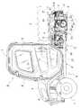
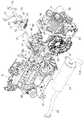
図1〜図3に示すように、操向操作自在な左右一対の前車輪1と、左右一対の後車輪2とを走行機体Aに備え、この走行機体Aの前部位置に運転部を構成するキャビンBを備え、走行機体Aの後部に荷台3を備え、この荷台3の下方位置に駆動部Cを備えて作業車が構成されている。Hereinafter, embodiments of the present invention will be described with reference to the drawings.
〔overall structure〕
As shown in FIGS. 1 to 3, the traveling machine body A is provided with a pair of left and right
この作業車は、駆動部Cからの駆動力を前車輪1と後車輪2とに伝える走行駆動系を有した4輪駆動型であり、農作業や運搬作業等の多目的の作業に使用されるユーティリティビークルとして構成されている。荷台3は、後端側が走行機体Aの後端位置に対して横向き姿勢の軸芯Pを中心にして揺動自在に支持され、ダンプシリンダ4の作動により前端側を上昇させて積載物を後方に排出できるように構成されている。 This work vehicle is a four-wheel drive type having a traveling drive system that transmits the driving force from the drive unit C to the
走行機体Aの前部位置には開閉自在にボンネット5を備えており、このボンネット5の左右下部には、前車輪1の上部を覆うフロントフェンダー6が配置されている。前記キャビンBは、キャビン本体7の前部にフロントガラス8を備え、この側部に対して開閉自在に備えられるドアー9を備えている。 A bonnet 5 is provided at the front portion of the traveling machine body A so as to be freely opened and closed. A front fender 6 is disposed at the left and right lower portions of the bonnet 5 so as to cover the upper portion of the
キャビンBには運転者が着座する運転座席11と、この運転座席11に隣接する位置で横長となる2人掛用の助手座席12とが備えられている。また、運転座席11の前部位置には前車輪1を操向制御するステアリングホイール13と、主変速レバー14と、パーキングレバー15とが備えられ、この下部位置には走行速度を制御する変速操作具としてのアクセルペダル16と、前車輪1及び後車輪2のブレーキ装置(図示せず)を操作するブレーキペダル17とが備えられている。 Cabin B is provided with a driver's
走行機体Aの後端側には、左右の後車輪2の上方を覆うリヤフェンダー18が備えられ、このリヤフェンダー18には、ブレーキランプ19が備えられている。 On the rear end side of the traveling machine body A, a
〔機体フレーム〕
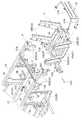
走行機体Aの強度メンバーとしての機体フレームFを備えている。この機体フレームFは図4に示すように、前後方向に伸びる左右一対のメインフレーム21と、このメインフレーム21の前部位置においてキャビンBを支持するキャビンフレームユニット22と、メインフレーム21の前端に連結する前部フレームユニット23と、メインフレーム21の後部位置の上方位置でメインフレーム21と平行姿勢となるように走行機体Aの前後方向に伸びる左右一対の上部フレーム24と、駆動部Cを支持する着脱フレームユニットGとを備えて構成されている。[Airframe frame]
A body frame F as a strength member of the traveling body A is provided. As shown in FIG. 4, the fuselage frame F includes a pair of left and right
メインフレーム21と上部フレーム24とは角パイプ状の鋼材が用いられ、キャビンフレームユニット22と前部フレームユニット23とは、角パイプ材やチャンネル材等の鋼材が用いられている。 The
キャビンフレームユニット22は、キャビンBの前部に配置される横向き姿勢のフレーム体と、運転座席11の下側に配置される横向き姿勢のフレーム体とを含む構造物として構成されている。前部フレームユニット23は、ボンネット5の下側に配置される構造物であり、この前部フレームユニット23の左右位置には、ダブルウイッシュボーン型に構成される上下一対の前部サスペンションアーム25の基端部を前後向き姿勢の揺動軸芯を中心にして揺動自在に支持している。また、前部サスペンションアーム25の上方への揺動時に圧縮される前部サスペンションスプリング26を有する前部サスペンションユニット27の下端が前部サスペンションアーム25に支持され、この前部サスペンションユニット27の上端を前部フレームユニット23が支持している。 The
左右のメインフレーム21と、この上部に配置される上部フレーム24とは縦向き姿勢で角パイプ状の鋼材で成る連結フレーム28によって連結されている。また、メインフレーム21の後端側に隣接する位置で上部フレーム24の下側にメインフレーム21と上部フレーム24とに対して分離自在に連結するように着脱フレームユニットGが配置されている。 The left and right
図6に示すように、駆動部Cは、エンジンEとミッションケースMと無段変速装置V(変速ユニットの一例)とを連結した構成を有しており、図5及び図6に示すように、着脱フレームユニットGは、駆動部Cの下側(上部フレーム24より下側)に配置されるマウントフレーム31と、このマウントフレーム31を左右の上部フレーム24に連結するように左右に2つずつ配置される断面形状コ字状の縦フレーム32と、マウントフレームの31の前端側に形成される横向き姿勢の前部フレーム33とを備えて構成されている。 As shown in FIG. 6, the drive unit C has a configuration in which an engine E, a transmission case M, and a continuously variable transmission V (an example of a transmission unit) are connected. As shown in FIGS. The detachable frame unit G includes a
この着脱フレームユニットGは、後述するように後車輪2を支持する機能も有するものであり、他のフレームから分離することにより、この着脱フレームユニットGに駆動部Cと後車輪2とを支持した状態で機体フレームFから取り外せるように構成されている。 The detachable frame unit G also has a function of supporting the
マウントフレーム31は、鋼板をプレス加工する等の加工によりリブ状部分を形成して強度を高めており、横幅が左右の上部フレーム24の左右間隔より短い寸法に設定されている。マウントフレーム31には、ミッションケースMを支持するように左右一対の後部マウント支持体34を備えている。また、マウントフレーム31の両端部と、上部フレーム24とを縦フレーム32で直線的に連結するため、左右の縦フレーム32は、上端側ほど機体外方に変位する傾斜姿勢で備えられている。 The
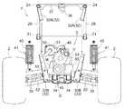
つまり、図4、図5、図8に示す如く、前後方向視において、上部に左右一対の上部フレーム24を備え、下部にマウントフレーム31(下部フレームUFの一例)を備え、両側部に上側ほど外側に変位する傾斜姿勢の縦フレーム32を備えることにより、左右の縦フレーム32の上端同士を結ぶ仮想ラインを上底とし、左右の縦フレーム32の下端同士を結ぶ仮想ラインを下底とした場合に、上底の長さが下底の長さより長い逆台形となるように夫々の位置関係が設定されている。 That is, as shown in FIGS. 4, 5, and 8, when viewed in the front-rear direction, a pair of left and right
縦フレーム32は、チャンネル状の鋼材が用いられ、上部フレーム24に上端が連結する上部部材32Aと、下端がマウントフレーム31に連結する下部部材32Bとを分離自在に連結した構造を有しており、上部部材32Aの一部と下部部材32Bの一部とを重ね合わせ、この重ね合わせ部分に挿通する連結ボルト32Sにより夫々が分離自在に連結されている。また、前部フレーム33の両端部にブラケット33Aを備え、このブラケット33Aに挿通する挿通ボルト33Sによりメインフレーム21の後端に対して分離自在に連結されている。 The
左右のメインフレーム21の後部近くに横向き姿勢で角パイプ状の鋼材で成る支持フレーム35(下部フレームUFの一例)が配置され、この支持フレーム35の左右端部のフランジ部35Aがメインフレーム21に対してフランジボルト35Sにより分離自在に連結している。また、支持フレーム35にはエンジンEを支持するように左右一対の前部マウント支持体36が形成されている。 A support frame 35 (an example of a lower frame UF) made of a square pipe-shaped steel material is disposed in a lateral orientation near the rear of the left and right
尚、マウントフレーム31として板材を用いる必要はなく、左右一対の角パイプ材を用いてマウントフレーム31を構成しても良い。また、縦フレーム32は中間部分で分離自在に構成されるものでなくても良く、例えば、縦フレーム32の上端部分が上部フレーム24に対して分離自在に連結される構成でも、縦フレーム32の下端部分がマウントフレーム31に対して分離自在に連結される構成でも良い。 It is not necessary to use a plate material as the
上部フレーム24の後端近くに架け渡される形態で、左右の上部フレーム24に両端部が連結する横向き姿勢で鋼材で成る横フレーム37が備えられ、この横フレーム37の中間位置にミッションケースMを吊り下げる形態で支持するための上部マウント支持体38が備えられ、この横フレーム37の両端部にはサスペンション支持部37Aが形成されている。 A
前述したメインフレーム21とマウントフレーム31と前部フレーム33と支持フレーム35とが、機体フレームFの下部位置に配置されるため、これらメインフレーム21とマウントフレーム31と前部フレーム33と支持フレーム35とを併せて下部フレームUFと称している。前述したようにマウントフレーム31と支持フレーム35と縦フレーム32の下部部材32Bとが、他のフレームに対して分離自在であるため、下部フレームUFの一部が分離自在に構成されていることになる。 Since the
前述した左右の縦フレーム32の下部部材32Bに対して、ダブルウィッシュボーン型に構成される上下一対の後部サスペンションアーム39の基端部を前後向き姿勢の揺動軸芯を中心にして揺動自在に支持している。また、後部サスペンションアーム39の上方への揺動時に圧縮される後部サスペンションスプリング40を有する後部サスペンションユニット41の下端が後部サスペンションアーム39に支持され、この後部サスペンションユニット41の上端を横フレーム37のサスペンション支持部37Aが支持している。尚、後部サスペンションユニット41の上端を上部フレーム24に支持して良く、この上部フレーム24に支持ブラケットを備え、この支持ブラケットに後部サスペンションユニット41の上端を支持しても良い。 With respect to the
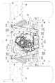
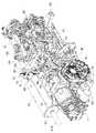
〔駆動部〕
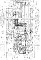
図3、図6、図7、図9、図10に示すように、エンジンEとミッションケースMと無段変速装置Vとを、この順序で連結することでエンジンEとミッションケースMと無段変速装置Vとが一体化された駆動部Cが構成されている。エンジンEの前端位置の下部の左右2箇所が支持フレーム35の左右一対の前部マウント支持体36に対し下部防振マウント45により支持され、ミッションケースMの後端位置の下部の左右2箇所がマウントフレーム31の左右一対の後部マウント支持体34に下部防振マウント45により支持され、ミッションケースMの上面に突設した吊下フレーム47の上端部が、上部マウント支持体38に対して上部防振マウント48により支持されている。〔Drive part〕
As shown in FIGS. 3, 6, 7, 9, and 10, the engine E, the transmission case M, and the continuously variable transmission V are connected in this order to connect the engine E, the transmission case M, and the continuously variable transmission. The drive part C with which the transmission V was integrated is comprised. The left and right two places at the lower part of the front end position of the engine E are supported by the lower anti-vibration mounts 45 with respect to the pair of left and right front mount supports 36 of the
これら下部防振マウント45と、上部防振マウント48とはブッシュ型の防振ゴムで構成され、駆動部Cから機体フレームFに伝えられる振動を抑制するように機能する。前述したようにマウントフレーム31の横幅が比較的短いため、ミッションケースMを支持する左右の下部防振マウント45の間隔が短く設計されており、駆動部Cの上端部が横方向に振動しやすい構成となっている。これに対して左右の上部フレーム24に亘って備えられる横フレーム37に対して、上部防振マウント48によりミッションケースMの上部が吊り下げられる形態で支持されているので、駆動部Cの横方向への振動を抑制できるものにしている。 The
ミッションケースMの上方位置の左側にはエンジンEの排気音を低減するように、上面に防熱用のカバー50を有したマフラー51を備えている。 A
ミッションケースMの内部構造は図面に示していないが、このミッションケースMは、無段変速装置Vで変速された駆動力を複数段に変速すると共に、前後進の切換を行うギヤ式の変速装置と、デファレンシャルギヤ(図示せず)とを内蔵している。 Although the internal structure of the transmission case M is not shown in the drawing, the transmission case M is a gear-type transmission that shifts the driving force changed by the continuously variable transmission V to a plurality of stages and switches between forward and backward. And a differential gear (not shown).
無段変速装置Vは、図6に示すように、エンジンEからの駆動力により作動するアキシャルプランジャ型の可変容量型の油圧ポンプ53と、この油圧ポンプ53から供給される作動油により回転するアキシャルプランジャ型の油圧モータ54とを備えており、後部側面には、図7及び図10に示すように、作動油を濾過する2つのオイルフィルタ55が着脱自在に備えられている。尚、2つのオイルフィルタ55のうちの一方が作動油を油圧ポンプに吸引するサクション側に配置され、他方が作動油を排出するドレン側に配置されている。 As shown in FIG. 6, the continuously variable transmission V includes an axial plunger type variable displacement
この駆動部Cでは、エンジンEが、その出力軸(クランク軸:図示せず)の軸芯を前後向き方向に設定した姿勢で備えられ、この出力軸に連結する伝動軸(図示せず)をミッションケースMに前後方向に貫通させることで、エンジンEの駆動力を無段変速装置Vの油圧ポンプ53に伝え、この無段変速装置Vの油圧モータ54からの駆動力をミッションケースMに伝える伝動系が構成されている。また、ミッションケースMでは駆動力を変速装置で変速し、デファレンシャルギヤから左右の後部出力軸61に伝え、この後部出力軸61から後輪駆動軸62を介して左右の後車輪2に伝えると共に、図3に示すように、下面側に形成した下部出力軸(図示せず)及びドライブシャフト63から前輪デファレンシャルギヤ64に伝え、更に、前輪駆動軸65から左右の前車輪1に伝えるように伝動系が構成されている。 In this drive unit C, the engine E is provided with a posture in which the axis of its output shaft (crankshaft: not shown) is set in the front-rear direction, and a transmission shaft (not shown) connected to this output shaft is provided. By passing through the transmission case M in the front-rear direction, the driving force of the engine E is transmitted to the
特に、ドライブシャフト63と、エンジンEの下部のオイルパンとが接触しないように、ミッションケースMの左右方向での中央位置を基準にして、エンジンEの左右方向での中央位置を左側に偏位させて配置している。尚、ミッションケースMの左右方向での中央位置を基準にして、エンジンEの左右方向での中央位置を右側に偏位させて配置し、ドライブシャフト63をエンジンEの下部の左側に配置しても良い。 In particular, the center position of the engine E in the left-right direction is shifted to the left with respect to the center position in the left-right direction of the transmission case M so that the
図6、図13に示す如く、無段変速装置Vは、油圧ポンプ53を下側に配置し油圧モータ54を上側に配置する構成から、この無段変速装置Vの上端レベルがミッションケースMの上面より上方に高い位置に設定され、無段変速装置Vの上端がミッションケースMの上面より上方に突出している。この無段変速装置Vの上方への突出量を抑制すると共に、無段変速装置Vの上部の左側部にマフラー51の配置空間を拡大するために、無段変速装置Vを、前後方向視において上端側を右側(外側)に変位させるように、この無段変速装置Vを傾斜姿勢に設定している。尚、無段変速装置Vを、前後方向視において上端側を左側(外側)に変位させるように、この無段変速装置Vを傾斜姿勢に設定すると共に、マフラー51を無段変速装置Vの右側に配置するように構成しても良い。更に、マフラー51を機体フレームFの外側に配置しても良い。 As shown in FIGS. 6 and 13, the continuously variable transmission V has a configuration in which the
その後端部が機体フレームFの後端より少し後方に突出する位置に無段変速装置Vが配置され、図5、図7に示すように、この後端部を保護するプロテクタ57が機体フレームFの後端に備えられている。このプロテクタ57は、左右の後部位置の縦フレーム32の下部部材32Bの後面に分離自在に連結するパイプフレーム57Aと、このパイプフレーム57Aに支持される縦壁状の保護プレート57Bとで構成され、パイプフレーム57Aを縦フレーム32から分離することで、機体フレームFからプロテクタ57を分離して、オイルフィルタ55の交換や、無段変速装置Vのメンテナンスを容易にする。 The continuously variable transmission V is disposed at a position where the rear end protrudes slightly rearward from the rear end of the body frame F, and as shown in FIGS. 5 and 7, a
図7、図9、図10に示すように、エンジンEは、上面の右側にエアークリーナ(図示せず)から空気が供給されるインテークマニホールド67を備え、左側にエグゾーストマニホールド68を備えており、このエグゾーストマニホールド68とマフラー51との間に排気管69が配置されている。 As shown in FIGS. 7, 9, and 10, the engine E includes an
マフラー51は、円筒状に成形され、後端には排気ガスを左側の下方に送り出すように屈曲した筒状の排気部51Aを備えている。このマフラー51の前端部は前ブラケット58によりミッションケースMの上面に支持され、後端部は後ブラケット59により無段変速装置Vの上面に支持されている。防熱用のカバー50は前端部がビス等によりミッションケースMの上面に支持され、後端部がビス等により無段変速装置Vの上面に支持されている。また、前述した排気部51Aは、荷台3を上昇させた場合に接触しない位置に配置され、この排気部51Aは、近傍に部材が存在しない空間に排気ガスを送り出すように排気方向が設定されている。図面には示していないが、マフラー51の前端部を支持する前ブラケット58と、後端部を支持する後ブラケット59とには、マフラー51に形成されたネジ孔に対してビス等で固定されており、前ブラケット58と後ブラケット59とには、マフラー51をミッションケースMに固定するビスが挿通する長孔が異なる姿勢で形成され、このように長孔の姿勢が設定されることによりマフラー51の寸法誤差や、取付位置の誤差等を吸収して取付を容易にしている。 The
前述したように機体フレームFの後端部は、後面視において逆台形となるように上部フレーム24とマウントフレーム31と左右の縦フレーム32とが配置されている。そして、無段変速装置Vの上部が右方向に変位するように無段変速装置Vを斜め姿勢で配置し、この無段変速装置Vの上部の左側で、逆台形の上部の左側の角部の内部(隅部)において横フレーム37の下側の近傍にマフラー51を配置することで機体フレームFの内部空間を有効に利用できるようにしている。また、平面視では図7に示す如くマフラー51は、横フレーム37の下側に重なり合う位置で、この横フレーム37の近傍に配置され、このマフラー51が後輪駆動軸62の上側に重なり合う位置に配置されている。前述したようにマフラー51を機体フレームFの内部の右側に配置しても良く、このように配置した場合にもマフラー51が後輪駆動軸62の上側に重なり合う位置に配置される。 As described above, the
特に、マフラー51は、カバー50により上面の殆どの部分が覆われており、このカバー50にはプレス加工により「HOT」(図示せず)の文字等が突出形成されている。また、カバー50では、プレス加工により突出形成される文字等の一部を開放することで上面に雨水等が溜まり難くしており、プレス加工で凹凸が形成することでカバー50の表面積が拡大して放熱効果を高めると同時に強度を高めている。このマフラー51は、排気管69の後端が連結固定しており、ミッションケースM等の近傍の部材が取付られた後においても、排気管69とマフラー51とを一体的に着脱できるように構成されている。 In particular, the upper part of the
〔駆動部の分離〕
前述したように、着脱フレームユニットGと、支持フレーム35とともに駆動部Cを機体フレームFから分離し、上部防振マウント48の部位を分離することにより、駆動部Cを下方に抜き出す形態で取り外せるように構成されている。(Separation of drive unit)
As described above, the drive unit C is separated from the body frame F together with the detachable frame unit G and the
具体的には、機体フレームFを全体的に持ち上げておき、挿通ボルト33Sを抜き取ることにより前部フレーム33のブラケット33Aをメインフレーム21から分離し、連結ボルト32Sの抜き取りにより左右の縦フレーム32を構成する上部部材32Aから下部部材32Bを分離(着脱フレームユニットGを分離)し、フランジボルト35Sの分離により支持フレーム35の両端のフランジ部35Aをメインフレーム21から分離し、上部防振マウント48の部位を分離し、後部サスペンションユニット41の上端又は後端を分離することになる。 Specifically, the body frame F is lifted as a whole, the
この分離を行うことによりエンジンEが下部防振マウント45により支持フレーム35に支持された状態で、かつ、ミッションケースMがマウントフレーム31に下部防振マウント45で支持された状態で、図13に示す如く、エンジンEとミッションケースMと無段変速装置Vとで成る駆動部Cが一体的に機体フレームFから下方に移動させる形態で取り外せる。また、この駆動部Cには、マフラー51が備えられ、左右の縦フレーム32には後部サスペンションアーム39を介して後車輪2が支持されているので、これらも駆動部Cとともに下方に取り外せるのである。 By performing this separation, the engine E is supported on the
特に、エンジンEとミッションケースMと無段変速装置Vとは重量物であり、これらを下方に移動させる形態で機体フレームFから取り外せるので、これらを上方に吊り上げる形態で取り外すものと比較すると、吊り上げるための設備を必要とせず、例えば、油圧ジャッキを利用して下方に加工させる形態での取り外しも可能となる。また、この作業車で前部フレーム33がメインフレーム21に連結しない構成を採用しても良く、このような構成を採用することでマウントフレーム31を分離する際の手間が軽減する。 In particular, the engine E, the transmission case M, and the continuously variable transmission V are heavy objects and can be removed from the fuselage frame F in a form in which they are moved downward. For example, it is possible to remove in the form of processing downward using a hydraulic jack. In addition, a configuration in which the
〔変速操作構造〕
図6、図7、図9〜図11に示すように、エンジンEとミッションケースMの下部位置とが連結され、これらの間の上部位置に隙間Hが形成されている。この隙間Hの状部を跨ぐ位置においてエンジンEの後部の上面と、ミッションケースMの前部で上方に突出する突出部Maとに亘って連結部材71を配置し、この連結部材71の前端をエンジンEにボルト連結し、後端をミッションケースMの突出部Maにボルト連結し、この連結によりエンジンEとミッションケースMとの連結強度の向上が図られている。[Speed change operation structure]
As shown in FIGS. 6, 7, and 9 to 11, the engine E and the lower position of the transmission case M are connected to each other, and a gap H is formed at the upper position between them. A connecting
この連結部材71の上部位置に横向き姿勢の中間軸芯Xと同軸芯上に筒状体72を設け、この筒状体72に対して回転自在に中間作動軸73が内嵌状態で支持されている。中間作動軸73の右側の端部にプレート状の入力アーム74の中間位置が連結し、中間作動軸73の左側の端部にベルクランク状の出力アーム75が連結し、この中間作動軸73の中間部分にニュートラルカム76が連結している。 A
筒状体72の外面にアーム状のステー77が固設され、変速操作具としてのアクセルペダル16に連係する第1操作手段としての操作ワイヤ78のアウタワイヤ78Aの端部がステー77に支持されている。また、操作ワイヤ78のインナワイヤ78Bの端部が入力アーム74の一方の端部に連結し、この入力アーム74の他方の端部には、この入力アーム74の作動力をエンジンEのスロットル機構Etに伝える第3操作手段としての調速ロッド79が連結している。 An arm-
無段変速装置Vの左側面には変速操作部80が配置され、この変速操作部80に水平姿勢で突設された変速操作軸81を揺動操作する変速操作アーム81Aが備えられている。この変速操作アーム81Aは図6に示す中立姿勢で、油圧ポンプ53から油圧モータ54に供給される作動油を遮断して走行を停止させ、変速操作アーム81Aを揺動操作することで油圧ポンプ53から油圧モータ54に供給する作動油を増大させ走行速度の増速を実現する。 A speed
変速操作アーム81Aに操作ロッド82の一方の端部が連結し、出力アーム75の一方のアームに操作ロッド82の他方の端部が連結している。出力アーム75の他方の端部には変速操作アーム81Aの急激な作動を抑制するオイルダンパ83を接続している。図12に示すように、ニュートラルカム76の外周には凹状のカム面76Aが形成されている。筒状体72に固設したアーム体84の突出端の支承部85に対して中間軸芯Xと平行姿勢の軸芯を中心にして揺動自在に中立復帰アーム86が支承され、この中立復帰アーム86にはニュートラルカム76のカム面76Aに係入可能な遊転ローラで成る当接部材87が支承され、この中立復帰アーム86の揺動端には中立復帰バネ88の付勢力を作用させている。 One end of the
この変速操作構造により、アクセルペダル16が踏み込み操作された場合には、インナワイヤ78Bが引き操作され、入力アーム74と中間作動軸73とが中間軸芯Xを中心にして回転する。この入力アーム74の回転に伴い調速ロッド79が引き操作され、この操作力でスロットル機構Etが増速方向に操作され、エンジン回転数が増大する。また、アクセルペダル16の踏み込み操作に伴う中間作動軸73の回転と一体的に出力アーム75が回転し、この回転に連動する操作ロッド82の押し操作により変速操作アーム81Aが増速の方向に操作され無段変速装置Vの増速が行われる。つまり、アクセルペダル16の踏み込み操作と連係してエンジン回転数を増大させることでエンジンストールを抑制しながら無段変速装置Vの駆動速度の増大で走行速度の増速を図るのである。 With this speed change operation structure, when the
また、アクセルペダル16の踏み込み操作が解除された場合には、アクセルペダル16からインナワイヤ78Bに作用する張力が大きく低下し、中立復帰アーム86に作用する中立復帰バネ88の付勢力により当接部材87がニュートラルカム76のカム面76Aに圧接して入り込むことにより、中間作動軸73を中立姿勢に戻し変速操作アーム81Aが停止位置まで戻されると共に、スロットル機構Etも減速位置に戻され、走行機体Aは停車する。 When the depression operation of the
つまり、この変速操作構造では、アクセルペダル16の踏み込み操作力が伝えられる第1操作手段としての操作ワイヤ78が機体右側に配置され、この操作ワイヤ78の操作力を無段変速装置Vの左側の変速操作部80に伝える第2操作手段としての操作ロッド82が機体左側に配置され、操作ワイヤ78の変速操作力をエンジンEの右側のスロットル機構Etに伝える第3操作手段としての調速ロッド79が機体右側に配置されている。このような配置から、中間作動軸73が中間軸芯Xを中心にして回転する構成を利用して、駆動部Cの両サイドの空間を有効に活用して変速操作を行えるのである。尚、この変速操作構造では、第1操作手段としての操作ワイヤ78等を機体左側に配置し、第2操作手段としての操作ロッド82等を機体右側に配置しても良い。また、スロットル機構Etを操作する操作系は機体左側と右側との何れに配置しても良い。 That is, in this speed change operation structure, the
〔実施形態の作用・効果〕
この作業車では、エンジンEとミッションケースMと無段変速装置Vとの連結により一体化して駆動部Cが構成されると共に、エンジンEとミッションケースMとが左右の下部防振マウント45により下部フレームUFに支持されているので、下部防振マウント45により駆動部Cの重量を受け止めることが可能となる。また、上部フレーム24に両端が支持される横フレーム37の中間部にミッションケースMの上部が上部防振マウント48で支持されているので、左右の下部防振マウント45の横幅方向での間隔が短くても、駆動部Cの上部の振動の抑制が可能となり、制振性に優れた支持を実現する。[Operation / Effect of Embodiment]
In this work vehicle, the drive unit C is configured by connecting the engine E, the transmission case M, and the continuously variable transmission V, and the engine E and the transmission case M are connected to each other by the left and right lower vibration isolation mounts 45. Since it is supported by the frame UF, the weight of the drive unit C can be received by the lower vibration-
無段変速装置Vの上部が走行機体Aの左右方向の一方に変位する斜め姿勢で配置されることで、機体左右方向で無段変速装置Vの他方側の空間が拡大するため、この無段変速装置Vが配置される空間が比較的狭くとも、この空間の内部にマフラー51を配置できることになる。また、ミッションケースMの前部位置においてミッションケースMを基準にして一方(左側)に偏位してエンジンEが配置され、このエンジンEの上部の一方(左側)にエグゾーストマニホールド68が形成され、このエンジンEの偏位と同じ方向にマフラー51が配置されているので、エンジン排気を直線的にマフラー51に供給する排気管69を直線的に形成する可能となり排気系の構成の簡素化を実現している。 Since the upper portion of the continuously variable transmission V is arranged in an oblique posture that is displaced in one of the left and right directions of the traveling machine body A, the space on the other side of the continuously variable transmission V is expanded in the left and right direction of the machine body. Even if the space in which the transmission V is disposed is relatively narrow, the
更に、前後方向視において左右一対の上部フレーム24と、斜め姿勢となる左右の縦フレーム32と、下部フレームUFとで逆台形となる空間が機体フレームFの内部に形成され、この逆台形となる機体フレームFの空間の内部で、上部の左右の角部の近傍位置にマフラー51を配置することにより、機体フレームFで保護される状態で、この機体フレームFの角部(隅部)にマフラー51を配置できる。 Further, a space that is an inverted trapezoid is formed in the fuselage frame F by the pair of left and right
このように前後方向視において機体フレームFが、逆台形に形成されるため、左右の上部フレーム24に連結する横フレーム37に後部サスペンションユニット41の上端を支持することにより、後部サスペンションユニット41の姿勢を後部サスペンションアーム39の揺動方向に平行する姿勢(後部サスペンションアーム39のアーム面に直交する姿勢)に近づけることが可能となり後部サスペンションアーム39の無理のない圧縮を行わせる。 Since the body frame F is formed in an inverted trapezoidal shape in the front-rear direction as described above, the posture of the
駆動部Cと、後車輪2の支持系とが着脱フレームユニットGに支持されているので、この着脱フレームユニットGを機体フレームFから分離することで、エンジンEとミッションケースMと無段変速装置Vとマフラー51と後車輪2とを一体的に機体フレームFから下側に抜き出す形態で取り外すことが可能にとなり、例えば、駆動部Cを上方に抜き出す構成と比較して、駆動部Cのメンテナンスが容易となる。 Since the drive unit C and the support system of the
つまり、ミッションケースMをマウントフレーム31に対して下部防振マウント45で支持し、マウントフレーム31に連結する縦フレーム32に後部サスペンションアーム39を揺動自在に支持し、この後部サスペンションアーム39に後車輪2を支持している。また、エンジンEを支持フレーム35に対して下部防振マウント45で支持している。このような構成から、縦フレーム32を分離し、支持フレーム35をメインフレーム21から分離することにより、エンジンEとミッションケースMと無段変速装置Vと後部サスペンションアーム39とマフラー51とを一体的に下方に引き出す形態で取り外すことが可能となり、ミッションケースMからの駆動力を後車輪2に伝える駆動系を分離しなくて済むことになり、分離のための操作が単純となる。 That is, the transmission case M is supported by the lower
エンジンEとミッションケースMとが下部で連結され、上部に形成された隙間Hを跨ぐ位置に配置される連結部材71でエンジンEの上部とミッションケースMの上部とを連結することで連結強度を高めている。また、連結部材71に対して横向き姿勢で備えた筒状体72に回転自在に中間作動軸73を支持し、この中間作動軸73の一方(右側)に対してアクセルペダル16の操作力を伝えて中間作動軸73を回転させ、中間作動軸73の他方(左側)から無段変速装置Vの変速操作アーム81Aを操作して変速を行う構成であるので、中間作動軸73においては機械的なガタツキやアソビを招くことがなく、駆動部Cの一方から他方変速操作力を高精度で無段変速装置Vに伝えて変速操作を実現する。 The engine E and the transmission case M are connected at the lower part, and the connection strength is obtained by connecting the upper part of the engine E and the upper part of the transmission case M with a connecting
特に、変速操作時には、無段変速装置VとエンジンEのスロットル機構Etと同時に操作することでエンジンストールを招くことのない増速を実現しており、アクセルペダル16の操作を解除した場合には、ニュートラルカム76のカム面76Aに対して遊転ローラで成る当接部材87が係入することで中間作動軸73を中立方向に回転させ、無段変速装置Vを中立位置に戻すと同時にスロットル機構Etを低速位置に操作することで走行の停止を実現する。 In particular, when the speed change operation is performed, the speed increase without causing the engine stall is realized by operating the continuously variable transmission V and the throttle mechanism Et of the engine E at the same time, and when the operation of the
〔別実施形態〕
本発明は、上記した実施形態以外に以下のように構成しても良い。[Another embodiment]
The present invention may be configured as follows in addition to the embodiment described above.
(a)図14に示すように、駆動部CがミッションケースMのみで構成され、このミッションケースMの下部の左右の前部位置と後部位置とを下部フレームUFに対して下部防振マウント45で支持すると共に、左右の上部フレーム24に架け渡された横フレーム37の中間部に対して上部防振マウント48によりミッションケースMの上部を支持する。この別実施形態では、エンジンEはミッションケースMに連結されず、エンジンEの駆動力を出力軸100によりミッションケースMに伝える構成を採用しており、このエンジンEは、その下部の左右の前部位置と後部位置とが下部フレームUFに対してエンジンマウント101で支持されている。(A) As shown in FIG. 14, the drive unit C is configured by only the mission case M, and the left and right front and lower positions of the lower part of the mission case M are set to the lower vibration isolation mount 45 with respect to the lower frame UF. In addition, the upper portion of the transmission case M is supported by the upper anti-vibration mount 48 with respect to the middle portion of the
このような構成からミッションケースMの全体の重量を下部防振マウント45で受け止めてミッションケースMの振動を抑制すると同時に、このミッションケースMの上部の横方向への振動を上部防振マウント48で抑制できる。 With this configuration, the entire weight of the transmission case M is received by the lower vibration isolation mount 45 to suppress the vibration of the transmission case M, and at the same time, the upper
(b)図15に示すように、駆動部CがエンジンEのみで構成され、このエンジンEの下部の左右の前部位置と後部位置とを下部フレームUFに対して下部防振マウント45で支持すると共に、左右の上部フレーム24に架け渡された横フレーム37の中間部に対して上部防振マウント48によりエンジンEの上部を支持する。この別実施形態では、ミッションケースMはエンジンEに連結されず、エンジンEの駆動力を出力軸100によりミッションケースMに伝える構成を採用しており、このミッションケースMは、その下部の左右の前部位置と後部位置とが下部フレームUFに対してミッションケースマウント102で支持されている。(B) As shown in FIG. 15, the drive unit C is composed of only the engine E, and the left and right front and rear positions of the lower part of the engine E are supported by the lower vibration isolation mount 45 with respect to the lower frame UF. At the same time, the upper portion of the engine E is supported by the upper
このような構成からエンジンEの全体の重量を下部防振マウント45で受け止めてエンジンEの振動を抑制すると同時に、このエンジンEの上部の横方向への振動を上部防振マウント48で抑制できる。 With this configuration, the entire weight of the engine E is received by the lower vibration isolation mount 45 to suppress the vibration of the engine E, and at the same time, the upper
(c)エンジンEとミッションケースMとを連結して構成される駆動部Cの下部を下部フレームUFに対して下部防振マウント45で支持すると共に、エンジンEの上部を上部防振マウント48により横フレーム37に支持するように構成する。(C) The lower part of the drive unit C configured by connecting the engine E and the transmission case M is supported by the lower vibration isolation mount 45 with respect to the lower frame UF, and the upper part of the engine E is supported by the upper
(d)駆動部CとしてエンジンEとミッションケースMとの配置が前後方向で逆となる構成のものに適用する。(D) The drive unit C is applied to a configuration in which the arrangement of the engine E and the transmission case M is reversed in the front-rear direction.
本発明は、上部フレームと下部フレームとを有し、車輪に駆動力を伝える駆動部を備えた作業車に利用することができる。 INDUSTRIAL APPLICABILITY The present invention can be used for a work vehicle that includes an upper frame and a lower frame and includes a drive unit that transmits driving force to wheels.
2 車輪(後車輪)
24 上部フレーム
37 横フレーム
39 サスペンションアーム(後部サスペンションアーム)
41 サスペンションユニット(後部サスペンションユニット)
45 下部防振マウント
48 上部防振マウント
A 走行機体
C 駆動部
E エンジン
F 機体フレーム
M ミッションケース
UF 下部フレーム2 wheels (rear wheels)
24
41 Suspension unit (rear suspension unit)
45
Claims (7)
Translated fromJapanese前記駆動部が、エンジンと、ミッションケースと、を連結して構成され、
前記走行機体の機体フレームが、前後に伸びる下部フレームと、前後に伸びる左右一対の上部フレームとを有し、
前記駆動部の左右両側の下部が、前記下部フレームに対して下部防振マウントにより支持され、
前記ミッションケースの上部が、左右の前記上部フレームに架け渡された横フレームの中間部であって、上面視で前記ミッションケースと重複する位置に備えられている上部防振マウントにより支持され、
前記下部防振マウントが第1軸芯周りに防振可能に構成され、
前記上部防振マウントが第2軸芯周りに防振可能に構成され、
前記第1軸芯と前記第2軸芯とが平面視で交差するように、前記下部防振マウントと前記上部防振マウントとが配置されている作業車。A work vehicle in which a drive unit is disposed at a rear position of the traveling machine body,
The drive unit is configured by connecting an engine and a mission case,
The aircraft frame of the traveling aircraft has a lower frame extending in the front-rear direction and a pair of left and right upper frames extending in the front-rear direction,
Lower portions on both the left and right sides of the drive unit are supported by a lower vibration isolation mount with respect to the lower frame,
The upper part of the mission case is an intermediate part of a horizontal frame spanned between the left and right upper frames, and is supported by an upper vibration isolation mount provided at a position overlapping the mission case in a top view,
The lower vibration isolation mount is configured to be capable of vibration isolation around the first axis.
The upper vibration-proof mount is configured to be capable of vibration-proof around the second axis,
A work vehiclein which the lower vibration isolation mount and the upper vibration isolation mount are arranged so that the first axis and the second axis intersect in a plan view .
前記駆動部が、ミッションケースのみで構成され、
前記走行機体の機体フレームが、前後に伸びる下部フレームと、前後に伸びる左右一対の上部フレームとを有し、
前記ミッションケースの左右両側の下部が、前記下部フレームに対して下部防振マウントにより支持され、
前記ミッションケースの上部が、左右の前記上部フレームに架け渡された横フレームの中間部であって、上面視で前記ミッションケースと重複する位置に備えられている上部防振マウントにより支持され、
前記下部防振マウントが第1軸芯周りに防振可能に構成され、
前記上部防振マウントが第2軸芯周りに防振可能に構成され、
前記第1軸芯と前記第2軸芯とが平面視で交差するように、前記下部防振マウントと前記上部防振マウントとが配置されている作業車。A work vehicle in which a drive unit is disposed at a rear position of the traveling machine body,
The drive unit is composed only of a mission case,
The aircraft frame of the traveling aircraft has a lower frame extending in the front-rear direction and a pair of left and right upper frames extending in the front-rear direction,
Lower portions of the left and right sides of the mission case are supported by a lower vibration isolation mount with respect to the lower frame,
The upper part of the mission case is an intermediate part of a horizontal frame spanned between the left and right upper frames, and is supported by an upper vibration isolation mount provided at a position overlapping the mission case in a top view,
The lower vibration isolation mount is configured to be capable of vibration isolation around the first axis.
The upper vibration-proof mount is configured to be capable of vibration-proof around the second axis,
A work vehiclein which the lower vibration isolation mount and the upper vibration isolation mount are arranged so that the first axis and the second axis intersect in a plan view .
前記駆動部が、エンジンのみで構成され、
前記走行機体の機体フレームが、前後に伸びる下部フレームと、前後に伸びる左右一対の上部フレームとを有し、
前記エンジンの左右両側の下部が、前記下部フレームに対して下部防振マウントにより支持され、
前記エンジンの上部が、左右の前記上部フレームに架け渡された横フレームの中間部であって、上面視で前記エンジンと重複する位置に備えられている上部防振マウントにより支持され、
前記下部防振マウントが第1軸芯周りに防振可能に構成され、
前記上部防振マウントが第2軸芯周りに防振可能に構成され、
前記第1軸芯と前記第2軸芯とが平面視で交差するように、前記下部防振マウントと前記上部防振マウントとが配置されている作業車。A work vehicle in which a drive unit is disposed at a rear position of the traveling machine body,
The drive unit is composed only of an engine,
The aircraft frame of the traveling aircraft has a lower frame extending in the front-rear direction and a pair of left and right upper frames extending in the front-rear direction,
Lower portions of the left and right sides of the engine are supported by a lower vibration isolation mount with respect to the lower frame,
The upper portion of the engine is an intermediate portion of a horizontal frame spanned between the left and right upper frames, and is supported by an upper vibration isolation mount provided at a position overlapping the engine in a top view,
The lower vibration isolation mount is configured to be capable of vibration isolation around the first axis.
The upper vibration-proof mount is configured to be capable of vibration-proof around the second axis,
A work vehiclein which the lower vibration isolation mount and the upper vibration isolation mount are arranged so that the first axis and the second axis intersect in a plan view .
前記上部防振マウントが、側面視において、前側と後側の前記下部防振マウントの間に位置するように構成されている請求項1乃至5の何れか一項に記載の作業車。The lower vibration-proof mount is provided in a pair of left and right on the front side and the rear side of the drive unit,
The work vehicle according to any one of claims 1 to 5, wherein the upper vibration-proof mount is configured to be positioned between the front and rear lower vibration-proof mounts in a side view.
Priority Applications (2)
| Application Number | Priority Date | Filing Date | Title |
|---|---|---|---|
| JP2011180915AJP5812759B2 (en) | 2011-08-22 | 2011-08-22 | Work vehicle |
| US13/418,846US8776939B2 (en) | 2011-08-22 | 2012-03-13 | Working vehicle |
Applications Claiming Priority (1)
| Application Number | Priority Date | Filing Date | Title |
|---|---|---|---|
| JP2011180915AJP5812759B2 (en) | 2011-08-22 | 2011-08-22 | Work vehicle |
Publications (2)
| Publication Number | Publication Date |
|---|---|
| JP2013043481A JP2013043481A (en) | 2013-03-04 |
| JP5812759B2true JP5812759B2 (en) | 2015-11-17 |
Family
ID=47742034
Family Applications (1)
| Application Number | Title | Priority Date | Filing Date |
|---|---|---|---|
| JP2011180915AActiveJP5812759B2 (en) | 2011-08-22 | 2011-08-22 | Work vehicle |
Country Status (2)
| Country | Link |
|---|---|
| US (1) | US8776939B2 (en) |
| JP (1) | JP5812759B2 (en) |
Families Citing this family (20)
| Publication number | Priority date | Publication date | Assignee | Title |
|---|---|---|---|---|
| US8827028B2 (en) | 2006-07-28 | 2014-09-09 | Polaris Industries Inc. | Side-by-side ATV |
| US7819220B2 (en)* | 2006-07-28 | 2010-10-26 | Polaris Industries Inc. | Side-by-side ATV |
| JP5530383B2 (en) | 2011-03-14 | 2014-06-25 | 株式会社クボタ | Work vehicle |
| WO2014178761A1 (en)* | 2013-04-29 | 2014-11-06 | Volvo Truck Corporation | A heavy vehicle comprising an individual wheel suspension |
| JP5826807B2 (en)* | 2013-09-30 | 2015-12-02 | 本田技研工業株式会社 | Power unit support structure for vehicles traveling on rough terrain |
| JP6133798B2 (en) | 2014-01-27 | 2017-05-24 | 株式会社クボタ | Work vehicle |
| WO2015129011A1 (en)* | 2014-02-27 | 2015-09-03 | 株式会社小松製作所 | Dump truck |
| JP6512968B2 (en) | 2015-07-02 | 2019-05-15 | 株式会社クボタ | Multipurpose work vehicle |
| JP6456785B2 (en)* | 2015-07-02 | 2019-01-23 | 株式会社クボタ | Multipurpose work vehicle |
| US10124659B2 (en) | 2015-07-02 | 2018-11-13 | Kubota Corporation | Utility work vehicle |
| CN105882785B (en)* | 2016-06-24 | 2019-03-15 | 宋习 | Wheel is to transfer robot |
| DE102016221653B3 (en)* | 2016-11-04 | 2018-05-03 | Bayerische Motoren Werke Aktiengesellschaft | Attachment of a drive unit to a vehicle body |
| JP6815228B2 (en)* | 2017-02-28 | 2021-01-20 | 株式会社クボタ | Work vehicle |
| US10502308B2 (en)* | 2016-12-22 | 2019-12-10 | Polaris Industries Inc. | Driveline for powersports vehicle |
| JP7009268B2 (en) | 2018-03-08 | 2022-01-25 | 株式会社クボタ | Work platform |
| US10941696B2 (en) | 2018-06-27 | 2021-03-09 | Kubota Corporation | Engine cover and work vehicle |
| JP7339089B2 (en)* | 2019-09-18 | 2023-09-05 | 株式会社クボタ | work vehicle |
| GB2598990B (en)* | 2020-08-06 | 2022-11-30 | Deere & Co | Utility vehicle automatic transmission powertrain mounting |
| US11772476B2 (en)* | 2020-08-06 | 2023-10-03 | Deere & Company | Utility vehicle automatic transmission powertrain mounting |
| US12291267B2 (en)* | 2023-01-05 | 2025-05-06 | Arctic Cat Inc. | Off-road vehicle engine mounting |
Family Cites Families (15)
| Publication number | Priority date | Publication date | Assignee | Title |
|---|---|---|---|---|
| US2864573A (en)* | 1954-02-05 | 1958-12-16 | Gen Motors Corp | Engine mounting |
| US3825090A (en)* | 1973-08-08 | 1974-07-23 | Gen Motors Corp | Rotary engine and transmission assembly mounting system |
| JPS61278423A (en)* | 1985-06-03 | 1986-12-09 | Suzuki Motor Co Ltd | Saddle riding type four wheel car |
| JPS63111382U (en)* | 1987-01-13 | 1988-07-18 | ||
| JPH01109186A (en)* | 1987-10-22 | 1989-04-26 | Honda Motor Co Ltd | Vehicle frame structure |
| SE466996B (en)* | 1987-12-03 | 1992-05-11 | Volvo Ab | DEVICE FOR SUSPENSION OF AN ENGINE IN A VEHICLE |
| US5205374A (en)* | 1991-06-13 | 1993-04-27 | Dana Corporation | Synthetic engine mount strut |
| JP2747668B2 (en)* | 1996-01-30 | 1998-05-06 | 川崎重工業株式会社 | Frame structure of a four-wheeled vehicle |
| JP3737238B2 (en)* | 1997-04-17 | 2006-01-18 | ヤンマー農機株式会社 | Engine anti-vibration support configuration |
| JP2005007995A (en)* | 2003-06-18 | 2005-01-13 | Yamaha Motor Co Ltd | Small vehicle |
| JP2006027466A (en) | 2004-07-16 | 2006-02-02 | Suzuki Motor Corp | Engine suspension device of saddle riding type vehicle |
| US7347490B2 (en)* | 2004-09-30 | 2008-03-25 | Honda Motor Co., Ltd. | Vehicle floor structure and vehicle body frame structure |
| JP4467054B2 (en)* | 2004-09-30 | 2010-05-26 | 本田技研工業株式会社 | Vehicle body frame structure |
| JP4783085B2 (en)* | 2005-07-29 | 2011-09-28 | 本田技研工業株式会社 | Power unit support structure |
| JP4383426B2 (en)* | 2006-05-08 | 2009-12-16 | 本田技研工業株式会社 | Power unit support device for vehicle |
- 2011
- 2011-08-22JPJP2011180915Apatent/JP5812759B2/enactiveActive
- 2012
- 2012-03-13USUS13/418,846patent/US8776939B2/enactiveActive
Also Published As
| Publication number | Publication date |
|---|---|
| US20130048406A1 (en) | 2013-02-28 |
| US8776939B2 (en) | 2014-07-15 |
| JP2013043481A (en) | 2013-03-04 |
Similar Documents
| Publication | Publication Date | Title |
|---|---|---|
| JP5812759B2 (en) | Work vehicle | |
| JP5681591B2 (en) | Work vehicle | |
| JP6004977B2 (en) | Work vehicle | |
| US9764767B2 (en) | Off-road wheeled side-by-side vehicle having a storage space | |
| JP6471464B2 (en) | Work vehicle | |
| CN100528682C (en) | Motorcycle | |
| WO2015114606A1 (en) | Off-road wheeled side-by-side vehicle | |
| WO2015114605A1 (en) | Off-road wheeled side-by-side vehicle | |
| WO2013066804A1 (en) | Systems and apparatus for a three-wheeled vehicle | |
| JP2007084000A (en) | Suspension structure for small vehicles | |
| JP4130395B2 (en) | Swing arm suspension | |
| CN100478244C (en) | Motorcycle with backseat foot-plates and dashboard | |
| JP7072449B2 (en) | Work vehicle | |
| JP2003212147A (en) | Frame for riding tractor | |
| JP6723117B2 (en) | Tractor | |
| JP5694085B2 (en) | Work vehicle | |
| JP5670844B2 (en) | Work vehicle | |
| JP5616030B2 (en) | Steering damper device for saddle-ride type vehicles | |
| JP5694086B2 (en) | Work vehicle | |
| JP6217837B2 (en) | Tractor | |
| JP6149760B2 (en) | Tractor | |
| JP6489189B2 (en) | Tractor | |
| JP4142377B2 (en) | Tractor | |
| JP5043398B2 (en) | Tractor | |
| JP2015160516A5 (en) |
Legal Events
| Date | Code | Title | Description |
|---|---|---|---|
| A621 | Written request for application examination | Free format text:JAPANESE INTERMEDIATE CODE: A621 Effective date:20130926 | |
| A977 | Report on retrieval | Free format text:JAPANESE INTERMEDIATE CODE: A971007 Effective date:20140618 | |
| A131 | Notification of reasons for refusal | Free format text:JAPANESE INTERMEDIATE CODE: A131 Effective date:20140626 | |
| A521 | Written amendment | Free format text:JAPANESE INTERMEDIATE CODE: A523 Effective date:20140825 | |
| A131 | Notification of reasons for refusal | Free format text:JAPANESE INTERMEDIATE CODE: A131 Effective date:20150122 | |
| A521 | Written amendment | Free format text:JAPANESE INTERMEDIATE CODE: A523 Effective date:20150317 | |
| TRDD | Decision of grant or rejection written | ||
| A01 | Written decision to grant a patent or to grant a registration (utility model) | Free format text:JAPANESE INTERMEDIATE CODE: A01 Effective date:20150818 | |
| A61 | First payment of annual fees (during grant procedure) | Free format text:JAPANESE INTERMEDIATE CODE: A61 Effective date:20150915 | |
| R150 | Certificate of patent or registration of utility model | Ref document number:5812759 Country of ref document:JP Free format text:JAPANESE INTERMEDIATE CODE: R150 |