Movatterモバイル変換


[0]ホーム

URL:


JP5811402B2 - Steering device - Google Patents

Steering device
Download PDF

Info

Publication number
JP5811402B2
JP5811402B2JP2011283515AJP2011283515AJP5811402B2JP 5811402 B2JP5811402 B2JP 5811402B2JP 2011283515 AJP2011283515 AJP 2011283515AJP 2011283515 AJP2011283515 AJP 2011283515AJP 5811402 B2JP5811402 B2JP 5811402B2
Authority
JP
Japan
Prior art keywords
steering
nut
sub
stopper
axial direction
Prior art date
Legal status (The legal status is an assumption and is not a legal conclusion. Google has not performed a legal analysis and makes no representation as to the accuracy of the status listed.)
Expired - Fee Related
Application number
JP2011283515A
Other languages
Japanese (ja)
Other versions
JP2013132950A (en
Inventor
崇 田代
崇 田代
Current Assignee (The listed assignees may be inaccurate. Google has not performed a legal analysis and makes no representation or warranty as to the accuracy of the list.)
JTEKT Corp
Original Assignee
JTEKT Corp
Priority date (The priority date is an assumption and is not a legal conclusion. Google has not performed a legal analysis and makes no representation as to the accuracy of the date listed.)
Filing date
Publication date
Application filed by JTEKT CorpfiledCriticalJTEKT Corp
Priority to JP2011283515ApriorityCriticalpatent/JP5811402B2/en
Priority to US13/721,600prioritypatent/US8657062B2/en
Priority to EP12198841.4Aprioritypatent/EP2610130B1/en
Priority to CN201210563797.7Aprioritypatent/CN103171617B/en
Publication of JP2013132950ApublicationCriticalpatent/JP2013132950A/en
Application grantedgrantedCritical
Publication of JP5811402B2publicationCriticalpatent/JP5811402B2/en
Expired - Fee Relatedlegal-statusCriticalCurrent
Anticipated expirationlegal-statusCritical

Links

Images

Classifications

Landscapes

Description

Translated fromJapanese

この発明は、ステアバイワイヤ式の操舵装置に関する。  The present invention relates to a steer-by-wire type steering apparatus.

ステアバイワイヤ式の操舵装置として特許文献1で開示された車両用操舵装置では、回転操作部材と車輪とが機械的に連結されておらず、回転操作部材の回転操作量に応じて制御される操舵用アクチュエータが車輪を転舵させる。
このようなステアバイワイヤ式の操舵装置では、回転操作部材の回転を検出する構成が重要であり、この構成に異常が生じてしまうと、操舵用アクチュエータが正常であっても、操舵不能になってしまう。回転操作部材の回転を検出する構成として、特許文献1では角度センサが1つしか設けられていないのだが、特許文献2の舵取装置では、当該構成の冗長化を図るために、メインの操舵角センサとバックアップ用の操舵角センサとが設けられている。そのため、特許文献2の舵取装置では、メインの操舵角センサの異常時においても、バックアップ用の操舵角センサによって操舵を継続できる。
In the vehicle steering apparatus disclosed in Patent Document 1 as a steer-by-wire steering apparatus, the rotation operation member and the wheel are not mechanically connected, and the steering is controlled according to the rotation operation amount of the rotation operation member. Actuators steer the wheels.
In such a steer-by-wire type steering device, a configuration for detecting the rotation of the rotary operation member is important. If an abnormality occurs in this configuration, steering becomes impossible even if the steering actuator is normal. End up. In Patent Literature 1, only one angle sensor is provided as a configuration for detecting the rotation of the rotation operation member. However, in the steering device ofPatent Literature 2, in order to make the configuration redundant, the main steering is provided. An angle sensor and a backup steering angle sensor are provided. Therefore, in the steering device ofPatent Document 2, even when the main steering angle sensor is abnormal, the steering can be continued by the backup steering angle sensor.

特開2001−114123号公報JP 2001-114123 A特開平10−278826号公報JP-A-10-278826

特許文献2の舵取装置では、操舵角センサの異常時においても操舵を継続できるようにするために同じ操舵角センサを2つ設けているので、不必要な部品点数増加やコスト上昇が不可避となる。
この発明は、かかる背景のもとでなされたもので、操舵角センサの異常時においても操舵を継続できる構成を、部品点数増加やコスト上昇を回避しつつ実現できるステアバイワイヤ式の操舵装置を提供することを目的とする。
In the steering device ofPatent Document 2, since the same steering angle sensor is provided in order to continue the steering even when the steering angle sensor is abnormal, an increase in the number of unnecessary parts and an increase in cost are inevitable. Become.
The present invention has been made based on such a background, and provides a steer-by-wire type steering device capable of realizing a configuration capable of continuing steering even when the steering angle sensor is abnormal while avoiding an increase in the number of parts and an increase in cost. The purpose is to do.

請求項1記載の発明は、操舵するための操作部材(2)を含む操作機構(3)と、前記操作機構とは機械的に非連結であって、前記操作部材の操舵に基づいて車輪(4)を転舵させる転舵機構(5)とを有する操舵装置(1)であって、前記操作機構は、前記操作部材の操舵角度(θ)を検出する操舵角センサ(8)と、前記操作部材の操舵方向を検出する操舵方向検出手段(11)とを含み、前記操舵方向検出手段は、前記操作部材の操舵方向に回転可能なねじシャフト(40)と、前記ねじシャフトに螺合するナット(41)と、前記ねじシャフトと平行に配置され、前記ねじシャフトの回転に伴って前記ナットをねじシャフトの軸方向(J)に沿って移動させるナットガイド(42)と、前記ナットガイドの長手方向の少なくとも一端側に設けられ、前記ナットが前記軸方向に所定位置以上移動することを規制するストッパ(43)と、前記ストッパに設けられ、前記ストッパに前記ナットが近接したことを検出する近接検出手段(92)と、前記操舵角センサに異常が発生したことに応答して、前記軸方向における前記ナットおよびストッパの間隔(Y)を狭める軸長可変機構(90)とを含むことを特徴とする、操舵装置である。  According to the first aspect of the present invention, the operation mechanism (3) including the operation member (2) for steering and the operation mechanism are mechanically disconnected, and the wheel ( 4) a steering device (1) having a steering mechanism (5) for steering, wherein the operation mechanism includes a steering angle sensor (8) for detecting a steering angle (θ) of the operation member; Steering direction detecting means (11) for detecting the steering direction of the operating member, and the steering direction detecting means is screwed onto the screw shaft and a screw shaft (40) rotatable in the steering direction of the operating member. A nut (41), a nut guide (42) that is arranged in parallel with the screw shaft and moves the nut along the axial direction (J) of the screw shaft as the screw shaft rotates; At least one end in the longitudinal direction A stopper (43) for restricting the nut from moving a predetermined position or more in the axial direction, and a proximity detecting means (92) for detecting the proximity of the nut to the stopper. And a variable shaft length mechanism (90) that narrows the distance (Y) between the nut and the stopper in the axial direction in response to an abnormality occurring in the steering angle sensor. It is.

請求項2記載の発明は、前記軸長可変機構は、前記ナットに設けられ、主部(80)、前記主部に内蔵される2つの副部(81)、前記各副部を前記主部から前記軸方向において前記ストッパ側へ離間するように付勢する付勢部材(82)、前記付勢部材の付勢力に抗して前記各副部を前記主部に拘束する拘束手段(83)、および、前記操舵角センサに異常が発生したことに応じて前記拘束手段による前記各副部の拘束を解除する解除手段(83)を含むことを特徴とする、請求項1記載の操舵装置である。  According to a second aspect of the present invention, the variable shaft length mechanism is provided on the nut, and includes a main portion (80), two sub-portions (81) built in the main portion, and the sub-portions are connected to the main portion. An urging member (82) for urging so as to be separated from the urging member toward the stopper in the axial direction, and a restraining means (83) for constraining each sub-part to the main part against the urging force of the urging member And a release means (83) for releasing the restraint of each sub-part by the restraint means in response to the occurrence of an abnormality in the steering angle sensor. is there.

請求項3記載の発明は、前記軸長可変機構は、前記ストッパに設けられ、主部(98)、前記主部に内蔵される副部(99)、前記副部を前記主部から前記軸方向において前記ナット側へ離間するように付勢する付勢部材(100)、前記付勢部材の付勢力に抗して前記副部を前記主部に拘束する拘束手段(105)、および、前記操舵角センサに異常が発生したことに応じて前記拘束手段による前記副部の拘束を解除する解除手段(105)を含むことを特徴とする、請求項1記載の操舵装置である。  According to a third aspect of the present invention, the variable shaft length mechanism is provided in the stopper, and includes a main part (98), a sub part (99) built in the main part, and the sub part from the main part to the shaft. An urging member (100) for urging so as to be separated toward the nut in the direction, a restraining means (105) for restraining the sub part against the main part against the urging force of the urging member, and The steering apparatus according to claim 1, further comprising a releasing means (105) for releasing the restraint of the sub part by the restraining means in response to an abnormality occurring in the steering angle sensor.

なお、上記において、括弧内の数字等は、後述する実施形態における対応構成要素の参照符号を表すものであるが、これらの参照符号により特許請求の範囲を限定する趣旨ではない。  In addition, in the above, the numbers in parentheses represent reference numerals of corresponding components in the embodiments described later, but the scope of the claims is not limited by these reference numerals.

請求項1記載の発明によれば、操作機構と転舵機構とが機械的に非連結なステアバイワイヤ式の操舵装置では、操舵角センサによって操作部材の操舵角度を検出するだけでなく、操舵方向検出手段によって操作部材の操舵方向を検出することもできる。よって、操舵角センサに異常が発生しても、転舵機構は、操舵方向検出手段が検出した操舵方向に基づいて車輪を転舵させることができる。つまり、操舵装置は、操舵角センサの異常時においても操舵を維持できる。  According to the first aspect of the present invention, in the steer-by-wire type steering device in which the operation mechanism and the steering mechanism are mechanically disconnected, not only the steering angle of the operation member is detected by the steering angle sensor but also the steering direction. The steering direction of the operation member can also be detected by the detection means. Therefore, even if an abnormality occurs in the steering angle sensor, the steering mechanism can steer the wheels based on the steering direction detected by the steering direction detection means. That is, the steering device can maintain steering even when the steering angle sensor is abnormal.

ここで、操舵方向を検出する操舵方向検出手段は、操作部材の操舵角度(操舵方向および操舵量の両方)を検出する操舵角センサに比べて簡素な構成である。具体的に、操舵方向検出手段は、ねじシャフト、ナット、ナットガイド、ストッパおよび近接検出手段を含む安価かつ簡素な構成であり、操作部材の操舵(ねじシャフトの回転)に伴ってナットがねじシャフトの軸方向に沿って移動してストッパに近接したことに基づいて、操作部材の操舵方向を検出できる。このような操舵方向検出手段を用いれば、操舵方向検出手段の代わりに操舵角センサを別途設ける場合に比べて、部品点数増加やコスト上昇を回避できる。  Here, the steering direction detecting means for detecting the steering direction has a simpler configuration than the steering angle sensor for detecting the steering angle (both the steering direction and the steering amount) of the operation member. Specifically, the steering direction detection means has an inexpensive and simple configuration including a screw shaft, a nut, a nut guide, a stopper, and a proximity detection means, and the nut is screw thread shaft as the operating member is steered (rotation of the screw shaft). The steering direction of the operating member can be detected based on the fact that it has moved along the axial direction of the actuator and has come close to the stopper. By using such a steering direction detection means, it is possible to avoid an increase in the number of parts and an increase in cost compared to the case where a steering angle sensor is provided separately instead of the steering direction detection means.

つまり、操舵角センサの異常時においても操舵を継続できる構成を、部品点数増加やコスト上昇を回避しつつ実現できる。
ここで、操舵装置は、軸長可変機構も含んでいる。これにより、操舵角センサに異常が発生すると、軸長可変機構によってナットおよびストッパの間隔が狭められることによって、操作部材の操舵を開始してからナットがストッパに近接するまでのタイミングが短くなるので、その分、操作部材の操舵に対する車輪の転舵の応答性を向上させることができる。
That is, it is possible to realize a configuration capable of continuing the steering even when the steering angle sensor is abnormal while avoiding an increase in the number of parts and an increase in cost.
Here, the steering device also includes a variable shaft length mechanism. As a result, when an abnormality occurs in the steering angle sensor, the interval between the nut and the stopper is shortened by the variable shaft length mechanism, and the timing from when the steering of the operating member is started until the nut approaches the stopper is shortened. Accordingly, it is possible to improve the responsiveness of the turning of the wheel with respect to the steering of the operation member.

請求項2記載の発明によれば、操舵角センサに異常が発生すると、ナットに設けられた軸長可変機構では、副部が、主部への拘束が解除されることによって、付勢部材の付勢力により主部からストッパ側へ離間するので、ナットおよびストッパの間隔を確実に狭めることができる。
請求項3記載の発明によれば、操舵角センサに異常が発生すると、ストッパに設けられた軸長可変機構では、副部が、主部への拘束が解除されることによって、付勢部材の付勢力により主部からナット側へ離間するので、ナットおよびストッパの間隔を確実に狭めることができる。
According to the second aspect of the present invention, when an abnormality occurs in the steering angle sensor, in the variable shaft length mechanism provided in the nut, the sub-part is released from the restriction on the main part, so that the biasing member Since the main portion separates from the main portion by the biasing force, the interval between the nut and the stopper can be reliably reduced.
According to the third aspect of the present invention, when an abnormality occurs in the steering angle sensor, in the variable shaft length mechanism provided in the stopper, the sub part is released from the restriction to the main part, so that the biasing member Since the urging force separates the main portion from the nut side, the interval between the nut and the stopper can be reliably reduced.

図1は、本発明の一実施形態における操舵装置1の概略構成を示す模式図である。FIG. 1 is a schematic diagram showing a schematic configuration of a steering device 1 according to an embodiment of the present invention.図2は、操舵装置1から操作機構3を抜き出して示した模式的な断面図であって、ナット41に設けられた軸長可変機構90の副部81が拘束位置にある様子を示している。FIG. 2 is a schematic cross-sectional view showing theoperation mechanism 3 extracted from the steering device 1, and shows a state where thesub-portion 81 of the variableshaft length mechanism 90 provided on thenut 41 is in the restraining position. .図3は、図2において副部81が解除位置にある様子を示している。FIG. 3 shows a state where thesub-portion 81 is in the release position in FIG.図4は、図2の変形例を示していて、ストッパ43に設けられた軸長可変機構90の副部99が拘束位置にある様子を示している。FIG. 4 shows a modification of FIG. 2 and shows a state where thesub-portion 99 of the shaft lengthvariable mechanism 90 provided in thestopper 43 is in the restraining position.図5は、図4において副部99が解除位置にある様子を示している。FIG. 5 shows a state in which thesub part 99 is in the release position in FIG.

本発明の好ましい実施の形態について、添付図面を参照しつつ説明する。
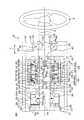
図1は、本発明の一実施形態における操舵装置1の概略構成を示す模式図である。図1を参照して、操舵装置1は、車両に適用される。操舵装置1は、ステアリングホイール等の回転可能な操作部材2を含む操作機構3と、操作部材2の操舵に基づいて車輪4を転舵させる転舵機構5とを有している。操舵装置1は、いわゆるステアバイワイヤ式の操舵装置であって、操作機構3と転舵機構5とが機械的に非連結となっている。
Preferred embodiments of the present invention will be described with reference to the accompanying drawings.
FIG. 1 is a schematic diagram showing a schematic configuration of a steering device 1 according to an embodiment of the present invention. With reference to FIG. 1, the steering device 1 is applied to a vehicle. The steering device 1 includes anoperation mechanism 3 including arotatable operation member 2 such as a steering wheel, and asteering mechanism 5 that steers the wheel 4 based on the steering of theoperation member 2. The steering device 1 is a so-called steer-by-wire steering device, and theoperation mechanism 3 and thesteering mechanism 5 are mechanically disconnected.

操作機構3は、操作部材2の他に、操作部材2の回転中心から延びる回転軸6と、回転軸6を回転可能に支持するハウジング7と、操舵角センサ8と、反力発生ユニット10と、操舵方向検出手段としての操舵方向検出ユニット11とを主に含んでいる。
回転軸6は、操作部材2に固定されている。これにより、操作部材2および回転軸6は、回転軸6の軸中心周りに一体回転可能である。そのため、操作部材2を回転操作したときの角度(「操舵角度」ということにする)は、回転軸6の回転角度と等しい。
In addition to theoperation member 2, theoperation mechanism 3 includes arotation shaft 6 extending from the rotation center of theoperation member 2, ahousing 7 that rotatably supports therotation shaft 6, asteering angle sensor 8, and a reactionforce generation unit 10. The steeringdirection detection unit 11 as a steering direction detection means is mainly included.
The rotatingshaft 6 is fixed to theoperation member 2. Thereby, theoperation member 2 and the rotatingshaft 6 can rotate integrally around the axis center of the rotatingshaft 6. Therefore, the angle when theoperation member 2 is rotated (hereinafter referred to as “steering angle”) is equal to the rotation angle of therotation shaft 6.

ハウジング7は、車体12に固定された中空円筒体であって、ハウジング7の中空部分に、回転軸6の一部(操作部材2側とは反対側の部分)が収容されている。
操舵角センサ8は、たとえばレゾルバやロータリーエンコーダー等であって、回転軸6の回転角度(つまり、操作部材2の操舵角度θ)を検出する。ここでの回転角度(操舵角度)は、回転軸6および操作部材2の回転量(操作部材2の操舵量)と、回転方向(操作部材2の操舵方向)とを含むベクトルである。操舵角センサ8は、ハウジング7に収容されている。
Thehousing 7 is a hollow cylindrical body fixed to thevehicle body 12, and a part of the rotating shaft 6 (a part opposite to theoperation member 2 side) is accommodated in the hollow part of thehousing 7.
Thesteering angle sensor 8 is, for example, a resolver or a rotary encoder, and detects the rotation angle of the rotating shaft 6 (that is, the steering angle θ of the operation member 2). Here, the rotation angle (steering angle) is a vector including the rotation amount of therotation shaft 6 and the operation member 2 (steering amount of the operation member 2) and the rotation direction (steering direction of the operation member 2). Thesteering angle sensor 8 is accommodated in thehousing 7.

反力発生ユニット10は、回転軸6に摺擦することによって回転軸6の回転に抵抗を与える。この抵抗が、操舵反力として操作部材2に与えられる。操作部材2を操作するユーザは、操作部材2に与えられた操舵反力によって、車輪4が路面から受ける反力を擬似的に体感できる。反力発生ユニット10は、ハウジング7に収容されている。
操舵方向検出ユニット11は、操作部材2の操舵方向を検出するものであり、以降で詳説する。
The reactionforce generating unit 10 gives resistance to the rotation of the rotatingshaft 6 by rubbing against the rotatingshaft 6. This resistance is given to theoperation member 2 as a steering reaction force. The user who operates theoperation member 2 can experience the reaction force that the wheel 4 receives from the road surface in a pseudo manner by the steering reaction force applied to theoperation member 2. The reactionforce generation unit 10 is accommodated in thehousing 7.
The steeringdirection detection unit 11 detects the steering direction of theoperation member 2 and will be described in detail later.

転舵機構5は、転舵軸13と、ハウジング14と、タイロッド15と、ナックルアーム16と、転舵アクチュエータ17とを主に含んでいる。
転舵軸13は、車体12の幅方向(車幅方向であり、図1では左右方向)に延びる軸状体である。
ハウジング14は、車幅方向に延びる中空体であり、その中空部分に転舵軸13が挿通されている。この状態で、転舵軸13の軸方向(車幅方向と同じ)における両端部は、ハウジング14からはみ出している。そして、転舵軸13は、車幅方向にスライド可能である。
Thesteering mechanism 5 mainly includes asteering shaft 13, ahousing 14, atie rod 15, aknuckle arm 16, and asteering actuator 17.
The steeredshaft 13 is a shaft-like body extending in the width direction of the vehicle body 12 (the vehicle width direction and the left-right direction in FIG. 1).
Thehousing 14 is a hollow body extending in the vehicle width direction, and the steeredshaft 13 is inserted through the hollow portion. In this state, both ends of the steeredshaft 13 in the axial direction (the same as the vehicle width direction) protrude from thehousing 14. The steeredshaft 13 is slidable in the vehicle width direction.

タイロッド15は、転舵軸13の軸方向両端部に対して1本ずつ連結されている。
ナックルアーム16は、各タイロッド15において転舵軸13に連結された側とは反対側の端部に連結されている。ナックルアーム16に対して車輪4が連結されている。
転舵アクチュエータ17は、一例として、電動モータ(図示せず)と、この電動モータの駆動力(電動モータの出力軸の回転力)を転舵軸13の軸方向のスライドに変換するボールねじ装置(図示せず)とを含む。転舵アクチュエータ17の電動モータ(図示せず)が駆動力を発生すると、転舵軸13が車幅方向にスライドし、このスライドが転舵軸13の軸方向両端部のタイロッド15に伝達されることで、ナックルアーム16が回動し、車輪4の転舵が達成される。
Onetie rod 15 is connected to each end of the steeredshaft 13 in the axial direction.
Theknuckle arm 16 is connected to the end of eachtie rod 15 opposite to the side connected to the steeredshaft 13. The wheel 4 is connected to theknuckle arm 16.
As an example, the steeringactuator 17 includes an electric motor (not shown) and a ball screw device that converts a driving force of the electric motor (rotational force of the output shaft of the electric motor) into an axial slide of the steeringshaft 13. (Not shown). When an electric motor (not shown) of the turningactuator 17 generates a driving force, the turningshaft 13 slides in the vehicle width direction, and this slide is transmitted to thetie rods 15 at both axial ends of the turningshaft 13. As a result, theknuckle arm 16 rotates and the wheel 4 is steered.

なお、図1では、各車輪4が右側へ少し転舵した状態を示しているが、車両が直進しているときの車輪4の位置に対応する操作部材2の位置(回転方向における位置)が、操舵中立位置である。
また、操舵装置1は、車速Vを検出する車速センサ18と、操舵角センサ8や操舵方向検出ユニット11や車速センサ18の検出信号が入力される制御装置19とをさらに含んでいる。制御装置19は、ECU(Electronic Control Unit)とも呼ばれ、マイクロコンピュータで構成されている。
1 shows a state in which each wheel 4 is slightly steered to the right, but the position of theoperation member 2 corresponding to the position of the wheel 4 when the vehicle is traveling straight (the position in the rotation direction) is The steering neutral position.
The steering device 1 further includes avehicle speed sensor 18 that detects the vehicle speed V, and acontrol device 19 that receives detection signals from thesteering angle sensor 8, the steeringdirection detection unit 11, and thevehicle speed sensor 18. Thecontrol device 19 is also called an ECU (Electronic Control Unit), and is constituted by a microcomputer.

車両の通常発進時や通常走行時において、制御装置19は、操舵角センサ8によって検出された操舵角度θや、車速センサ18によって検出された車速Vに基づいて目標転舵角を設定し、この目標転舵角まで車輪4が転舵するように、転舵アクチュエータ17を駆動制御する。
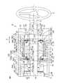
図2は、操舵装置1から操作機構3を抜き出して示した模式的な断面図であって、ナット41に設けられた軸長可変機構90の副部81が拘束位置にある様子を示している。図3は、図2において副部81が解除位置にある様子を示している。
When the vehicle starts normally or travels normally, thecontrol device 19 sets a target turning angle based on the steering angle θ detected by thesteering angle sensor 8 and the vehicle speed V detected by thevehicle speed sensor 18. The steeringactuator 17 is driven and controlled so that the wheels 4 are steered to the target turning angle.
FIG. 2 is a schematic cross-sectional view showing theoperation mechanism 3 extracted from the steering device 1, and shows a state where thesub-portion 81 of the variableshaft length mechanism 90 provided on thenut 41 is in the restraining position. . FIG. 3 shows a state where thesub-portion 81 is in the release position in FIG.

次に、図2および図3を参照して操作機構3、特に、操舵方向検出ユニット11について詳しく説明する。なお、図2では、操舵角センサ8の図示を省略している。また、図2に図示された操作部材2を時計回り(時計方向)に回転させると車輪4(図1参照)が右向きに転舵し、操作部材2を反時計回り(反時計方向)に回転させると車輪4が左向きに転舵するものとする。  Next, theoperation mechanism 3, in particular, the steeringdirection detection unit 11 will be described in detail with reference to FIGS. In FIG. 2, thesteering angle sensor 8 is not shown. When theoperation member 2 shown in FIG. 2 is rotated clockwise (clockwise), the wheel 4 (see FIG. 1) is steered to the right, and theoperation member 2 is rotated counterclockwise (counterclockwise). Then, the wheel 4 is steered to the left.

操作機構3において、前述したハウジング7は、図2では、横方向に延びており、ハウジング7において、横方向一端面(図2における右端面)には、丸い一端開口20が形成されていて、横方向他端面(図2における左端面)には、丸い他端開口21が形成されている。ハウジング7の中空部分は、一端開口20および他端開口21を介して外部に連通している。  In theoperation mechanism 3, thehousing 7 described above extends in the lateral direction in FIG. 2. In thehousing 7, a round oneend opening 20 is formed on one end surface in the lateral direction (the right end surface in FIG. 2). On the other end surface in the horizontal direction (left end surface in FIG. 2), a round other end opening 21 is formed. The hollow portion of thehousing 7 communicates with the outside through oneend opening 20 and theother end opening 21.

ハウジング7において、一端開口20を縁取る部分は、やや厚い環状板をなすフランジ22になっている。フランジ22の内周面において、ハウジング7の外部から最も遠い側(図2における左側)の端部には、径方向内側へ突出する位置決め凸部23が一体的に設けられている。また、フランジ22の内周面において、ハウジング7の外部から最も近い側(図2における右側)の端部には、周方向全域に亘って径方向外側へ窪む環状溝24が形成されている。環状溝24には、環状またはC字形状の位置決めリング25が径方向内側から嵌め込まれている。一端開口20には、環状の軸受26が同軸状で嵌め込まれている。軸受26は、位置決め凸部23と位置決めリング25とによって両側から挟持されることによって、ハウジング7に位置決めされている。  In thehousing 7, a portion that borders the oneend opening 20 is aflange 22 that forms a slightly thick annular plate. On the inner peripheral surface of theflange 22, a positioningconvex portion 23 that protrudes radially inward is integrally provided at an end portion on the side farthest from the outside of the housing 7 (left side in FIG. 2). Further, on the inner peripheral surface of theflange 22, anannular groove 24 is formed in the end portion on the side closest to the outside of the housing 7 (the right side in FIG. 2). . An annular or C-shapedpositioning ring 25 is fitted into theannular groove 24 from the radially inner side. Anannular bearing 26 is fitted coaxially into the oneend opening 20. Thebearing 26 is positioned on thehousing 7 by being clamped from both sides by thepositioning projection 23 and thepositioning ring 25.

ハウジング7の中空部分においてフランジ22側とは反対側の領域には、ホルダ27が収容されている。ホルダ27は、ハウジング7と同軸状をなす中空円筒状であり、軸方向一端が塞がれていて、軸方向他端が開放されている。ホルダ27は、ハウジング7においてフランジ22以外の部分の内径とほぼ同じ外径を有する円周壁28と、円周壁28の軸方向一端に連結される円板状の端壁29とを一体的に備えている。  Aholder 27 is accommodated in a region opposite to theflange 22 side in the hollow portion of thehousing 7. Theholder 27 has a hollow cylindrical shape that is coaxial with thehousing 7, one end in the axial direction is closed, and the other end in the axial direction is open. Theholder 27 integrally includes acircumferential wall 28 having an outer diameter that is substantially the same as the inner diameter of the portion other than theflange 22 in thehousing 7, and a disk-shapedend wall 29 that is coupled to one axial end of thecircumferential wall 28. ing.

ホルダ27は、ハウジング7に対して他端開口21から嵌め込まれている。ホルダ27では、端壁29が、他の部分よりもハウジング7の一端開口20側(図2における右側)に位置している。円周壁28の外周面がハウジング7の内周面に接続されることによって、ホルダ27は、ハウジング7に対して一体化されており、ハウジング7の一部になっている。円周壁28において、端壁29が連結された側とは反対側の軸方向他端縁によって区画された部分は、開口30となっている。開口30は、ハウジング7の他端開口21と軸方向J(ハウジング7およびホルダ27の軸方向)において同じ位置にある。開口30および他端開口21を介してホルダ27の中空部分がハウジング7の外部に連通している。円周壁28の内周面において開口30の周囲の領域には、ねじ部31が形成されている。  Theholder 27 is fitted into thehousing 7 from theother end opening 21. In theholder 27, theend wall 29 is located closer to the oneend opening 20 of thehousing 7 than the other part (the right side in FIG. 2). By connecting the outer peripheral surface of thecircumferential wall 28 to the inner peripheral surface of thehousing 7, theholder 27 is integrated with thehousing 7 and is a part of thehousing 7. In thecircumferential wall 28, a portion defined by the other axial end edge opposite to the side to which theend wall 29 is connected is anopening 30. Theopening 30 is in the same position as the other end opening 21 of thehousing 7 in the axial direction J (the axial direction of thehousing 7 and the holder 27). The hollow portion of theholder 27 communicates with the outside of thehousing 7 through theopening 30 and theother end opening 21. A threadedportion 31 is formed in a region around theopening 30 on the inner peripheral surface of thecircumferential wall 28.

端壁29の円中心位置には、端壁29を厚さ方向(軸方向J)に貫通する丸い軸挿通孔32が形成されている。端壁29では、軸挿通孔32を縁取る部分が、端壁29の内周面となっている。端壁29の内周面において開口30側の端部(図2における左端部)には、径方向内側へ突出する位置決め凸部33が一体的に設けられている。軸挿通孔32には、環状の軸受34が同軸状で嵌め込まれている。軸受34は、位置決め凸部33によって開口30側(図2における左側)から当接されることによって、ハウジング7に位置決めされている。  A roundshaft insertion hole 32 that penetrates theend wall 29 in the thickness direction (axial direction J) is formed at a circular center position of theend wall 29. In theend wall 29, a portion that borders theshaft insertion hole 32 is an inner peripheral surface of theend wall 29. On the inner peripheral surface of theend wall 29, an end portion on theopening 30 side (left end portion in FIG. 2) is integrally provided with a positioningconvex portion 33 that protrudes inward in the radial direction. Anannular bearing 34 is coaxially fitted in theshaft insertion hole 32. Thebearing 34 is positioned on thehousing 7 by abutting from theopening 30 side (left side in FIG. 2) by the positioningconvex portion 33.

操舵方向検出ユニット11は、ねじシャフト40と、ナット41と、ナットガイド42と、ストッパ43と、近接検出手段としての近接検出センサ92とを含んでいる。
ねじシャフト40は、軸状体であって、回転軸6に対して同軸状で連結されている。ねじシャフト40と回転軸6とは一体形成されていてもよいし、分離可能であってもよい。ねじシャフト40は、回転軸6に近い側から順に、第1ねじ形成部45、第1支持部46、第2ねじ形成部47および第2支持部48を一体的に有している。
The steeringdirection detection unit 11 includes ascrew shaft 40, anut 41, anut guide 42, astopper 43, and aproximity detection sensor 92 as proximity detection means.
Thescrew shaft 40 is a shaft-like body and is connected to therotating shaft 6 coaxially. Thescrew shaft 40 and therotating shaft 6 may be integrally formed or may be separable. Thescrew shaft 40 integrally includes a firstscrew forming portion 45, afirst support portion 46, a secondscrew forming portion 47, and asecond support portion 48 in order from the side close to therotating shaft 6.

第1ねじ形成部45の外周面には、ねじ部49が形成されている。
第1支持部46の外周面は、凹凸のない円周面である。第1支持部46は、第1ねじ形成部45とほぼ同径である。
第2ねじ形成部47は、第1支持部46よりも少し大径である。そのため、第2ねじ形成部47において第1支持部46に隣接する端部には、段付き51が形成されている。第2ねじ形成部47の外周面には、ねじ部52が形成されている。なお、ねじ部52は、第2ねじ形成部47の外周面の全域に形成されていなくてもよい。図2では、第2ねじ形成部47の外周面において段付き51周辺の領域には、ねじ部52が形成されていない。
Ascrew portion 49 is formed on the outer peripheral surface of the firstscrew forming portion 45.
The outer peripheral surface of the1st support part 46 is a circumferential surface without an unevenness | corrugation. Thefirst support portion 46 has substantially the same diameter as the firstscrew forming portion 45.
The secondscrew forming portion 47 has a slightly larger diameter than thefirst support portion 46. Therefore, a steppedportion 51 is formed at an end portion of the secondscrew forming portion 47 adjacent to thefirst support portion 46. Ascrew portion 52 is formed on the outer peripheral surface of the secondscrew forming portion 47. Thescrew portion 52 may not be formed on the entire outer peripheral surface of the secondscrew forming portion 47. In FIG. 2, thescrew portion 52 is not formed in the region around the stepped 51 on the outer peripheral surface of the secondscrew forming portion 47.

第2支持部48の外周面は、凹凸のない円周面である。第2支持部48は、第2ねじ形成部47よりも少し小径である。そのため、第2ねじ形成部47において第2支持部48に隣接する端部には、段付き53が形成されている。
ねじシャフト40は、ハウジング7の一端開口20および他端開口21に挿通された状態でハウジング7に部分的に収容されている。また、ねじシャフト40は、ハウジング7内のホルダ27の開口30および軸挿通孔32に挿通された状態でホルダ27に部分的に収容されている。このとき、ねじシャフト40は、ハウジング7およびホルダ27のそれぞれに対して同軸状になっている。そのため、ねじシャフト40(回転軸6)の軸方向は、前述した軸方向Jと同じである。
The outer peripheral surface of the2nd support part 48 is a circumferential surface without an unevenness | corrugation. Thesecond support portion 48 has a slightly smaller diameter than the secondscrew forming portion 47. For this reason, a steppedportion 53 is formed at the end of the secondscrew forming portion 47 adjacent to thesecond support portion 48.
Thescrew shaft 40 is partially accommodated in thehousing 7 while being inserted into the oneend opening 20 and the other end opening 21 of thehousing 7. Thescrew shaft 40 is partially accommodated in theholder 27 in a state of being inserted through theopening 30 of theholder 27 and theshaft insertion hole 32 in thehousing 7. At this time, thescrew shaft 40 is coaxial with each of thehousing 7 and theholder 27. Therefore, the axial direction of the screw shaft 40 (rotating shaft 6) is the same as the axial direction J described above.

ねじシャフト40では、第1ねじ形成部45における大部分(第1支持部46側の端部を除く部分)が、一端開口20からハウジング7の外にはみ出しており、回転軸6につながっている。第1支持部46は、前述した軸受26に対して内嵌されている。
ここで、第1ねじ形成部45のねじ部49に対して、環状の位置決めナット54が径方向外側から螺合しており、位置決めナット54は、軸受26に対してハウジング7の外側から当接している。位置決めナット54は、ねじシャフト40の一部とみなすことができる。軸受26は、位置決めナット54および段付き51によって軸方向Jにおける両側から挟持されることで、ねじシャフト40に対して位置決めされている。
In thescrew shaft 40, most of the first screw forming portion 45 (the portion excluding the end portion on thefirst support portion 46 side) protrudes from the oneend opening 20 to the outside of thehousing 7 and is connected to therotating shaft 6. . Thefirst support portion 46 is fitted into the bearing 26 described above.
Here, anannular positioning nut 54 is screwed into thescrew portion 49 of the firstscrew forming portion 45 from the outside in the radial direction, and thepositioning nut 54 comes into contact with the bearing 26 from the outside of thehousing 7. ing. Thepositioning nut 54 can be regarded as a part of thescrew shaft 40. Thebearing 26 is positioned with respect to thescrew shaft 40 by being clamped from both sides in the axial direction J by thepositioning nut 54 and the steppedportion 51.

また、ねじシャフト40では、第2ねじ形成部47が、ハウジング7の中空部分においてフランジ22とホルダ27の端壁29とに挟まれた領域(「検出領域」ということにする)Xに配置されている。
第2支持部48は、ホルダ27の中空部分に配置されている。第2支持部48において第2ねじ形成部47側の端部は、前述した軸受34に対して内嵌されている。ここで、軸受34は、第2ねじ形成部47において第2支持部48側の段付き53とホルダ27の端壁29における位置決め凸部33とによって軸方向Jにおける両側から挟持されることで、ねじシャフト40に対して位置決めされている。
In thescrew shaft 40, the secondscrew forming portion 47 is disposed in a region X (referred to as “detection region”) between theflange 22 and theend wall 29 of theholder 27 in the hollow portion of thehousing 7. ing.
Thesecond support portion 48 is disposed in the hollow portion of theholder 27. An end of thesecond support portion 48 on the secondscrew forming portion 47 side is fitted into the bearing 34 described above. Here, thebearing 34 is sandwiched from both sides in the axial direction J by the steppedportion 53 on thesecond support portion 48 side and the positioningconvex portion 33 on theend wall 29 of theholder 27 in the secondscrew forming portion 47. Positioned relative to thescrew shaft 40.

ねじシャフト40は、軸受26および軸受34が位置決めされた軸方向Jにおける2箇所において、ハウジング7(ホルダ27も含む)によって回転可能に支持されている。ねじシャフト40は、回転軸6を介して操作部材2につながっているので、ねじシャフト40の回転方向(図2における1点鎖線の矢印を参照)は、操作部材2の操舵方向と同じである。つまり、ねじシャフト40は、操作部材2の操舵方向に回転可能である。また、操作部材2の操舵角度θ(図1参照)は、ねじシャフト40の回転角度と等しい。  Thescrew shaft 40 is rotatably supported by the housing 7 (including the holder 27) at two locations in the axial direction J where thebearing 26 and thebearing 34 are positioned. Since thescrew shaft 40 is connected to theoperation member 2 via therotation shaft 6, the rotation direction of the screw shaft 40 (refer to the one-dot chain line arrow in FIG. 2) is the same as the steering direction of theoperation member 2. . That is, thescrew shaft 40 can rotate in the steering direction of theoperation member 2. Further, the steering angle θ (see FIG. 1) of theoperation member 2 is equal to the rotation angle of thescrew shaft 40.

ここで、ナット41、ナットガイド42、ストッパ43および近接検出センサ92よりも先に、前述した反力発生ユニット10について説明する。反力発生ユニット10は、ホルダ27に収容されている。反力発生ユニット10は、ねじシャフト40の第2支持部48を非接触で取り囲む環状のプラグ61と、プラグ61よりも端壁29側において第2支持部48に対して外嵌される環状の摺擦リング62と、摺擦リング62に対して外嵌される環状の押圧リング63と、プラグ61および押圧リング63間に圧縮状態で介装されるばね64とを含む。  Here, the reactionforce generation unit 10 described above will be described prior to thenut 41, thenut guide 42, thestopper 43, and theproximity detection sensor 92. The reactionforce generation unit 10 is accommodated in theholder 27. The reactionforce generating unit 10 includes anannular plug 61 that surrounds thesecond support portion 48 of thescrew shaft 40 in a non-contact manner, and anannular plug 61 that is externally fitted to thesecond support portion 48 on theend wall 29 side of theplug 61. It includes a rubbingring 62, an annularpressing ring 63 fitted on the rubbingring 62, and aspring 64 interposed between theplug 61 and thepressing ring 63 in a compressed state.

プラグ61の外周面には、ねじ部65が形成されており、ねじ部65は、ホルダ27のねじ部31に対して径方向内側から螺合している。摺擦リング62の外周面62Aおよび押圧リング63の内周面63Aは、いずれも、プラグ61から離れる方向(図2における右側)に向かうに従って拡径する円錐面であり、互いに面接触している。押圧リング63は、ばね64によってプラグ61から離れる方向へ付勢されつつ、内周面63Aによって摺擦リング62を径方向内側へ押圧している。これにより、太線矢印で示すように、摺擦リング62が縮径され、摺擦リング62の内周面62Bがねじシャフト40の第2支持部48に対して圧接している。操作部材2の操舵に伴ってねじシャフト40を回転させると、第2支持部48と摺擦リング62の内周面62Bとの間の摩擦が、前述した操舵反力として操作部材2に与えられる。プラグ61を押圧リング63側へねじ込むと、ばね64の付勢力が強くなるので、その分、第2支持部48と摺擦リング62の内周面62Bとの間の摩擦が大きくなり、操舵反力も大きくなる。このように、プラグ61のねじ込み量によって、操舵反力を調整できる。  Ascrew part 65 is formed on the outer peripheral surface of theplug 61, and thescrew part 65 is screwed into thescrew part 31 of theholder 27 from the radially inner side. Both the outerperipheral surface 62A of the rubbingring 62 and the innerperipheral surface 63A of thepressing ring 63 are conical surfaces that expand in diameter in a direction away from the plug 61 (right side in FIG. 2), and are in surface contact with each other. . Thepressing ring 63 presses the rubbingring 62 radially inward by the innerperipheral surface 63 </ b> A while being urged away from theplug 61 by thespring 64. As a result, as shown by the thick arrow, the diameter of the rubbingring 62 is reduced, and the innerperipheral surface 62B of the rubbingring 62 is in pressure contact with thesecond support portion 48 of thescrew shaft 40. When thescrew shaft 40 is rotated along with the steering of theoperation member 2, the friction between thesecond support portion 48 and the innerperipheral surface 62 </ b> B of the rubbingring 62 is given to theoperation member 2 as the steering reaction force described above. . When theplug 61 is screwed into thepressing ring 63 side, the urging force of thespring 64 is increased, so that the friction between thesecond support portion 48 and the innerperipheral surface 62B of the rubbingring 62 is increased, and the steering reaction is reduced. Power also increases. Thus, the steering reaction force can be adjusted by the screwing amount of theplug 61.

ナット41は、円管状である。図2では、説明の便宜上、ナット41の断面に相当する部分に、右上に延びるハッチングを付している。ナット41の内周面には、ねじ部55が形成されている。ナット41は、その基礎(大部分)をなす主部80と、主部80に対して軸方向に相対移動可能に設けられた副部81と、副部81を軸方向に付勢する付勢部材82と、拘束手段および解除手段としての電磁クラッチ83とを含んでいる。  Thenut 41 is a circular tube. In FIG. 2, for convenience of explanation, a portion corresponding to the cross section of thenut 41 is hatched extending to the upper right. A threadedportion 55 is formed on the inner peripheral surface of thenut 41. Thenut 41 includes amain portion 80 that forms the basis (most part) of thenut 41, a sub-portion 81 that is provided so as to be relatively movable in the axial direction with respect to themain portion 80, and a bias that biases the sub-portion 81 in the axial direction. A member 82 and an electromagnetic clutch 83 as a restraining means and a releasing means are included.

主部80は、ナット41の内周面を区画する円管状の内周部84と、内周部84に対して同軸状で配置されて内周部84を非接触で取り囲む円管状の外周部85と、径方向に延びて内周部84および外周部85のそれぞれの軸方向略中央部分同士をつなぐ環状の連結部86とを一体的に有している。このような主部80では、ナット41の軸中心(1点鎖線参照)に対する片側部分の断面が、I形状になっており、主部80全体の断面形状は、アルファベット「E」を2つ背中合わせにつなげた形状になっている。  Themain portion 80 includes a tubular innerperipheral portion 84 that defines the inner peripheral surface of thenut 41, and a circular tubular outer peripheral portion that is arranged coaxially with the innerperipheral portion 84 and surrounds the innerperipheral portion 84 in a non-contact manner. 85 and an annular connectingportion 86 that extends in the radial direction and connects the substantially central portions of the innerperipheral portion 84 and the outerperipheral portion 85 in the axial direction. In such amain portion 80, the cross section of one side of thenut 41 with respect to the axial center (see the one-dot chain line) has an I shape, and the cross section of themain portion 80 as a whole has two alphabets “E” back to back. It is connected to the shape.

内周部84の内周面に、前述したねじ部55が形成されている。連結部86において軸方向における両端面のそれぞれには、環状凹部87が形成されている。各環状凹部87は、軸方向から見て環状であって、連結部86と内周部84との境界において内周部84を取り囲みつつ窪んでいる。連結部86の軸方向両側の環状凹部87同士は連通していない。  The aforementioned threadedportion 55 is formed on the inner peripheral surface of the innerperipheral portion 84. Anannular recess 87 is formed on each end face of the connectingportion 86 in the axial direction. Eachannular recess 87 is annular when viewed from the axial direction, and is recessed while surrounding the innerperipheral portion 84 at the boundary between the connectingportion 86 and the innerperipheral portion 84. The annular recesses 87 on both sides in the axial direction of the connectingportion 86 do not communicate with each other.

外周部85の内周面において軸方向における両端縁には、径方向内側へ張り出す抜止リブ88が一体的に設けられている。当該両端縁のそれぞれにおいて、抜止リブ88は、環状につながっていてもよいし、完全な環状でなく、周方向途中で途切れていてもよい。外周部85には、外周部85(つまり、ナット41)を軸方向(肉厚方向)に貫通する丸い挿通孔56が形成されている。挿通孔56は、単数または複数(この実施形態では2つ)形成されており、複数形成される場合には、周方向に等間隔で形成されている。  On both end edges in the axial direction on the inner peripheral surface of the outerperipheral portion 85, retainingribs 88 projecting radially inward are integrally provided. In each of the both end edges, the retainingrib 88 may be connected in a ring shape, or may not be a complete ring shape, but may be interrupted in the circumferential direction. The outerperipheral portion 85 is formed with around insertion hole 56 that penetrates the outer peripheral portion 85 (that is, the nut 41) in the axial direction (thickness direction). One or a plurality of insertion holes 56 (two in this embodiment) are formed. When a plurality of insertion holes 56 are formed, they are formed at equal intervals in the circumferential direction.

副部81は、環状であり、連結部86の軸方向両側に1つずつ(合計2つ)設けられている。各副部81は、内周部84に対して外嵌され、かつ、外周部85に対して内嵌されており、内周部84と外周部85との間において、内周部84および外周部85と同軸状で配置されている。つまり、各副部81は、主部80に内蔵されている。この状態で、各副部81は、内周部84と外周部85との間に対して遊嵌されており、軸方向で同じ側の抜止リブ88と連結部86との間の範囲において、軸方向にスライド可能である。詳しくは、各副部81は、連結部86に当接する拘束位置(図2参照)と、連結部86から離間して軸方向で同じ側の抜止リブ88に当接する解除位置(図3参照)との間でスライド可能である。  The sub-portions 81 are annular and are provided one on each side in the axial direction of the connecting portion 86 (two in total). Eachsub-portion 81 is externally fitted to the innercircumferential portion 84 and is fitted to the outercircumferential portion 85, and the innercircumferential portion 84 and the outer circumferential portion are interposed between the innercircumferential portion 84 and the outercircumferential portion 85. It is arranged coaxially with theportion 85. That is, eachsub part 81 is built in themain part 80. In this state, each sub-portion 81 is loosely fitted between the innerperipheral portion 84 and the outerperipheral portion 85, and in the range between the retainingrib 88 and the connectingportion 86 on the same side in the axial direction, It can slide in the axial direction. Specifically, each sub-portion 81 has a restraining position (see FIG. 2) in contact with the connectingportion 86 and a release position in contact with the retainingrib 88 on the same side in the axial direction apart from the connectingportion 86. Can slide between.

解除位置にある副部81は、抜止リブ88に当接することによって、内周部84と外周部85との間から外れ不能になっている(図3参照)。
また、各副部81において、軸方向で同じ側の環状凹部87と軸方向で対向する位置には、環状凹部89が形成されている。環状凹部89は、軸方向から見て副部81の内周縁に沿う環状であって、軸方向で同じ側の環状凹部87から離間する方向へ窪んでいる。
The sub-portion 81 in the release position cannot be detached from between the innerperipheral portion 84 and the outerperipheral portion 85 by contacting the retaining rib 88 (see FIG. 3).
In each sub-portion 81, anannular recess 89 is formed at a position facing theannular recess 87 on the same side in the axial direction in the axial direction. Theannular recess 89 is annular along the inner peripheral edge of the sub-portion 81 when viewed from the axial direction, and is recessed in a direction away from theannular recess 87 on the same side in the axial direction.

付勢部材82は、たとえば、コイルばねであって、連結部86の軸方向両側に1つずつ設けられている。各付勢部材82は、内周部84に対して外嵌されている。合計2つの付勢部材82のうち、一方の付勢部材82は、軸方向における連結部86の一方側(図2における左側)において、当該一方側の副部81の環状凹部89と環状凹部87との間において圧縮状態で配置されている。他方の付勢部材82は、軸方向における連結部86の他方側(図2における右側)において、当該他方側の副部81の環状凹部89と環状凹部87との間において圧縮状態で配置されている。各付勢部材82は、副部81を主部80の連結部86から離間するように付勢している。  The urging member 82 is, for example, a coil spring, and is provided one on each side in the axial direction of the connectingportion 86. Each urging member 82 is externally fitted to the innerperipheral portion 84. Of the two urging members 82 in total, one urging member 82 is on one side (left side in FIG. 2) of the connectingportion 86 in the axial direction, and the annularconcave portion 89 and the annularconcave portion 87 of the sub-portion 81 on the one side. Are arranged in a compressed state. The other biasing member 82 is disposed in a compressed state between theannular recess 89 and theannular recess 87 of the sub-portion 81 on the other side of the connectingportion 86 in the axial direction (the right side in FIG. 2). Yes. Each biasing member 82 biases the sub-portion 81 so as to be separated from the connectingportion 86 of themain portion 80.

電磁クラッチ83は、連結部86における各副部81との対向面に設けられる第1クラッチ部83Aと、各副部81における連結部86との対向面に設けられる第2クラッチ部83Bとを含んでいる。電磁クラッチ83は、前述した制御装置19(図1参照)に対して電気的に接続されていて、制御装置19が電磁クラッチ83のON・OFFを制御する。  Theelectromagnetic clutch 83 includes a firstclutch portion 83A provided on the surface of thecoupling portion 86 facing the sub-portions 81, and a secondclutch portion 83B provided on the surface of the sub-portions 81 facing thecoupling portion 86. It is out. Theelectromagnetic clutch 83 is electrically connected to the control device 19 (see FIG. 1) described above, and thecontrol device 19 controls ON / OFF of theelectromagnetic clutch 83.

この実施形態では、電磁クラッチ83は、図2に示すように、ONされることによってつながっていて、連結部86(主部80)の第1クラッチ部83Aと各副部81の第2クラッチ部83Bとが密着している。そのため、ONされた状態にある電磁クラッチ83は、各付勢部材82の付勢力に抗して、各副部81を、前述した拘束位置に位置決めして、主部80に拘束している。一方、電磁クラッチ83は、OFFされることによって切れてしまい、第1クラッチ部83Aと各副部81の第2クラッチ部83Bとが密着しなくなる。そのため、電磁クラッチ83は、OFFされることによって、主部80に対する各副部81の拘束を解除する。これにより、各副部81は、付勢部材82の付勢力によって、解除位置まで移動する(図3参照)。  In this embodiment, as shown in FIG. 2, theelectromagnetic clutch 83 is connected by being turned on, and the firstclutch portion 83 </ b> A of the connecting portion 86 (main portion 80) and the second clutch portion of each sub-portion 81. 83B is in close contact. Therefore, the electromagnetic clutch 83 in the ON state is restrained by themain part 80 by positioning eachsub part 81 at the restraining position described above against the biasing force of each biasing member 82. On the other hand, theelectromagnetic clutch 83 is disconnected by being turned off, and the firstclutch portion 83A and the secondclutch portion 83B of each sub-portion 81 do not come into close contact with each other. Therefore, when theelectromagnetic clutch 83 is turned off, the restraint of each sub-part 81 with respect to themain part 80 is released. Thereby, eachsub part 81 moves to the release position by the urging force of the urging member 82 (see FIG. 3).

主部80、副部81、付勢部材82および電磁クラッチ83のまとまり、つまりナット41全体は、軸長可変機構90を構成している。軸長可変機構90の具体的な機能については、以降で説明する。
このようなナット41は、前述した検出領域Xに配置されていて、ねじシャフト40の第2ねじ形成部47に対して外嵌されている。このとき、ナット41のねじ部55が第2ねじ形成部47のねじ部52に対して螺合している。つまり、ナット41は、ねじシャフト40に螺合しているとともに、ねじシャフト40と同軸状になっている。そのため、ナット41の軸方向は、前述した軸方向Jと同じである。
A group of themain part 80, thesub part 81, the urging member 82, and the electromagnetic clutch 83, that is, theentire nut 41 constitutes a variableshaft length mechanism 90. Specific functions of the variableshaft length mechanism 90 will be described later.
Such anut 41 is disposed in the detection region X described above and is externally fitted to the secondscrew forming portion 47 of thescrew shaft 40. At this time, thescrew portion 55 of thenut 41 is screwed into thescrew portion 52 of the secondscrew forming portion 47. That is, thenut 41 is screwed to thescrew shaft 40 and is coaxial with thescrew shaft 40. Therefore, the axial direction of thenut 41 is the same as the axial direction J described above.

ナットガイド42は、軸状体であり、ナット41の挿通孔56と同じ数(ここでは2つ)だけ設けられている。ナットガイド42は、検出領域Xにおいて、ねじシャフト40の第2ねじ形成部47と平行に配置されていて、ナット41の挿通孔56に対して1つずつ挿通されている。つまり、各ナットガイド42(詳しくは両端の間の部分)は、対応する挿通孔56においてナット41を貫通している。  The nut guides 42 are shaft-like bodies and are provided in the same number (two here) as the insertion holes 56 of thenut 41. In the detection region X, thenut guide 42 is disposed in parallel with the secondscrew forming portion 47 of thescrew shaft 40 and is inserted through theinsertion hole 56 of thenut 41 one by one. That is, each nut guide 42 (specifically, a portion between both ends) passes through thenut 41 in thecorresponding insertion hole 56.

ストッパ43は、軸方向Jに薄くハウジング7の径方向に沿って延びる板状体であって、検出領域Xにおけるハウジング7の内周面に固定されており、当該内周面からねじシャフト40の第2ねじ形成部47側へ延びている。ストッパ43は、ナット41の軸方向両側に設けられている。なお、図2では、説明の便宜上、ストッパ43の断面に相当する部分に、右下に延びるハッチングを付している。  Thestopper 43 is a plate-like body that is thin in the axial direction J and extends along the radial direction of thehousing 7, and is fixed to the inner peripheral surface of thehousing 7 in the detection region X, and thescrew shaft 40 extends from the inner peripheral surface. It extends to the secondscrew forming portion 47 side. Thestoppers 43 are provided on both sides of thenut 41 in the axial direction. In FIG. 2, for convenience of explanation, the portion corresponding to the cross section of thestopper 43 is hatched extending to the lower right.

図2において、軸方向Jにおける同じ位置に表れている2つのストッパ43(ナット41に対して軸方向Jの両側における上下2つのストッパ43)は、第2ねじ形成部47を非接触で取り囲む環状体の一部として一体化されている。そのため、ナット41の2つの挿通孔56に対して軸方向両側のそれぞれに、細長板状かつ環状をなすストッパ43が1つずつ(合計2つ)設けられている。各ストッパ43の内周部には、ナット41側へ突出する環状の突出部91が一体的に設けられている。突出部91は、ナット41の内周部84よりも大径かつ外周部85よりも小径である。  In FIG. 2, two stoppers 43 (upper and lower twostoppers 43 on both sides in the axial direction J with respect to the nut 41) appearing at the same position in the axial direction J surround the secondscrew forming portion 47 in a non-contact manner. It is integrated as part of the body. Therefore, oneelongated stopper 43 and an annular stopper 43 (two in total) are provided on both axial sides of the twoinsertion holes 56 of thenut 41. Anannular protrusion 91 that protrudes toward thenut 41 is integrally provided on the inner peripheral portion of eachstopper 43. The protrudingportion 91 has a larger diameter than the innerperipheral portion 84 of thenut 41 and a smaller diameter than the outerperipheral portion 85.

各ストッパ43の突出部91において、軸方向Jで同じ側の副部81を臨む位置には、前述した近接検出センサ92が設けられている。この実施形態における近接検出センサ92は、通常はOFFになっているが、外部の物(ここでは副部81)に当接されることによってONになるスイッチである。なお、近接検出センサ92は、外部の物がすぐ近くまで近接したときにONになってもよい。つまり、近接検出センサ92は、外部の物による当接や近接を検出するセンサである。各ストッパ43の近接検出センサ92は、軸方向Jで同じ側の副部81に対してナット41の外側から、軸方向Jに沿って対向している。そのため、各副部81は、付勢部材82によって、軸方向Jにおいて同じ側の近接検出センサ92(ストッパ43)側へ主部80(連結部86)から離間するように付勢されていることになる。  In the protrudingportion 91 of eachstopper 43, theproximity detection sensor 92 described above is provided at a position facing the sub-portion 81 on the same side in the axial direction J. Theproximity detection sensor 92 in this embodiment is a switch that is normally turned off, but is turned on by contacting an external object (here, the sub-portion 81). Note that theproximity detection sensor 92 may be turned on when an external object comes close to the immediate vicinity. That is, theproximity detection sensor 92 is a sensor that detects contact or proximity by an external object. Theproximity detection sensor 92 of eachstopper 43 faces theauxiliary portion 81 on the same side in the axial direction J along the axial direction J from the outside of thenut 41. Therefore, each sub-part 81 is urged by the urging member 82 so as to be separated from the main part 80 (connecting part 86) toward the proximity detection sensor 92 (stopper 43) on the same side in the axial direction J. become.

そして、ナット41の各挿通孔56に挿通されたナットガイド42は、軸方向Jにおける挿通孔56の両側に位置する各ストッパ43に固定されている。そのため、ストッパ43は、ナットガイド42の長手方向(軸方向Jと同じ)の両端に1つずつ設けられていて、ナットガイド42の長手方向における一端側および他端側を保持している。これにより、ナットガイド42がナット41の挿通孔56に挿通された状態が維持されている。  The nut guides 42 inserted into the insertion holes 56 of thenut 41 are fixed to thestoppers 43 located on both sides of theinsertion hole 56 in the axial direction J. Therefore, onestopper 43 is provided at each end of thenut guide 42 in the longitudinal direction (same as the axial direction J), and holds one end side and the other end side in the longitudinal direction of thenut guide 42. Thereby, the state in which thenut guide 42 is inserted through theinsertion hole 56 of thenut 41 is maintained.

ここで、各ナットガイド42は、挿通孔56に対して、若干の遊びを持って挿通されていてもよい。
図2を参照して、ユーザが操作部材2を操舵することによって時計方向または反時計方向に回転させると、回転軸6およびねじシャフト40も操作部材2と共回りする。このとき、ねじシャフト40に螺合したナット41もねじシャフト40と共回りしようとする。しかし、ナット41の各挿通孔56に対してナットガイド42が挿通されていることによって、ナット41は回転できず、代わりに、ナットガイド42(換言すれば、ねじシャフト40の軸方向J)に沿ってスライドする。つまり、ナットガイド42は、ねじシャフト40の回転に伴ってナット41をねじシャフト40の軸方向Jに沿って移動させる。
Here, eachnut guide 42 may be inserted into theinsertion hole 56 with some play.
Referring to FIG. 2, when the user turns theoperation member 2 clockwise or counterclockwise, therotating shaft 6 and thescrew shaft 40 also rotate together with theoperation member 2. At this time, thenut 41 screwed into thescrew shaft 40 also tries to rotate together with thescrew shaft 40. However, since thenut guide 42 is inserted into eachinsertion hole 56 of thenut 41, thenut 41 cannot be rotated. Instead, in the nut guide 42 (in other words, the axial direction J of the screw shaft 40). Slide along. That is, thenut guide 42 moves thenut 41 along the axial direction J of thescrew shaft 40 as thescrew shaft 40 rotates.

たとえば、ユーザが操作部材2(換言すれば、ねじシャフト40)を図2における時計方向に回転させると、ナット41は、ナットガイド42に沿って操作部材2に近付く方向(図2における右側)へスライドする。そして、操作部材2を引き続き同じ方向へ回転させると、最終的に、操作部材2に最も近い側(図2における右側)のストッパ43の突出部91が、右側からナット41の内周部84と外周部85との間に入り込み、右側の副部81が当該突出部91の近接検出センサ92に当接(近接)し、この近接検出センサ92がONになる。これにより、ナット41は、これ以上スライドできなくなり、操作部材2は、これ以上同じ方向(時計方向)に回転させることができなくなる。つまり、図2におけるナット41の右側において、近接検出センサ92は、ストッパ43の突出部91にナット41の副部81が当接(近接)したことを検出し、ストッパ43は、ナット41がストッパ43に当接する所定位置以上、軸方向J(図2における右側)に移動することを規制する。  For example, when the user rotates the operation member 2 (in other words, the screw shaft 40) in the clockwise direction in FIG. 2, thenut 41 moves toward theoperation member 2 along the nut guide 42 (right side in FIG. 2). Slide. Then, when theoperation member 2 is continuously rotated in the same direction, the protrudingportion 91 of thestopper 43 on the side closest to the operation member 2 (the right side in FIG. 2) finally comes into contact with the innerperipheral portion 84 of thenut 41 from the right side. Theright side sub-portion 81 comes into contact with (adjacent to) theproximity detection sensor 92 of theprojection 91, and theproximity detection sensor 92 is turned on. As a result, thenut 41 can no longer slide, and theoperation member 2 cannot be rotated further in the same direction (clockwise). That is, on the right side of thenut 41 in FIG. 2, theproximity detection sensor 92 detects that thesub-portion 81 of thenut 41 is in contact (proximity) with the protrudingportion 91 of thestopper 43. The movement in the axial direction J (on the right side in FIG. 2) beyond a predetermined position in contact with 43 is restricted.

逆に、ユーザが操作部材2を図2における反時計方向に回転させると、ナット41は、ナットガイド42に沿って操作部材2から離れる方向(図2における左側)へスライドする。そして、操作部材2を引き続き同じ方向へ回転させると、最終的に、操作部材2から最も遠い側(図2における左側)のストッパ43の突出部91が、左側からナット41の内周部84と外周部85との間に入り込み、左側の副部81が当該突出部91の近接検出センサ92に当接(近接)し、この近接検出センサ92がONになる。これにより、ナット41は、これ以上スライドできなくなり、操作部材2は、これ以上同じ方向(反時計方向)に回転させることができなくなる。つまり、図2におけるナット41の左側において、近接検出センサ92は、ストッパ43の突出部91にナット41の副部81が当接(近接)したことを検出し、ストッパ43は、ナット41がストッパ43に当接する所定位置以上、軸方向J(図2における左側)に移動することを規制する。  Conversely, when the user rotates theoperation member 2 in the counterclockwise direction in FIG. 2, thenut 41 slides along thenut guide 42 in a direction away from the operation member 2 (left side in FIG. 2). Then, when theoperation member 2 is continuously rotated in the same direction, the protrudingportion 91 of thestopper 43 on the side farthest from the operation member 2 (left side in FIG. 2) finally comes into contact with the innerperipheral portion 84 of thenut 41 from the left side. Theleft sub-portion 81 comes into contact with (adjacent to) theproximity detection sensor 92 of theprojection 91, and theproximity detection sensor 92 is turned on. As a result, thenut 41 can no longer slide, and the operatingmember 2 can no longer be rotated in the same direction (counterclockwise). That is, on the left side of thenut 41 in FIG. 2, theproximity detection sensor 92 detects that thesub-portion 81 of thenut 41 is in contact (proximity) with the protrudingportion 91 of thestopper 43. The movement in the axial direction J (left side in FIG. 2) beyond a predetermined position in contact with 43 is restricted.

近接検出センサ92がONになったことは、制御装置19(図1参照)に入力される。制御装置19は、図2における右側の近接検出センサ92がONになれば、操作部材2の操舵方向が図2における時計方向であると判断し、図2における左側の近接検出センサ92がONになれば、操作部材2の操舵方向が図2における反時計方向であると判断する。このように、制御装置19には、操舵角センサ8が検出した操舵角度θ(図1参照)だけでなく、いずれかの近接検出センサ92がONになったという情報(操作部材2の操舵方向)も入力されるようになっている。  The fact that theproximity detection sensor 92 is turned on is input to the control device 19 (see FIG. 1). When theproximity detection sensor 92 on the right side in FIG. 2 is turned on, thecontrol device 19 determines that the steering direction of theoperation member 2 is the clockwise direction in FIG. 2, and theproximity detection sensor 92 on the left side in FIG. If so, it is determined that the steering direction of theoperation member 2 is the counterclockwise direction in FIG. As described above, thecontrol device 19 includes not only the steering angle θ detected by the steering angle sensor 8 (see FIG. 1) but also information that any one of theproximity detection sensors 92 is turned on (the steering direction of theoperation member 2). ) Is also entered.

図1を参照して、たとえば、操舵角センサ8に異常が発生した場合には、制御装置19には、操舵角センサ8から検出結果(操舵角度θ)が入力されなくなる。この場合、制御装置19は、操舵方向検出ユニット11の近接検出センサ92から入力された情報(いずれかの近接検出センサ92がONになったという情報)によって、ユーザによる操作部材2の操舵方向を取得する。そして、図2における右側の近接検出センサ92がONになった場合(操作部材2の操舵方向が時計方向である場合)には、当該近接検出センサ92がONである期間または当該近接検出センサ92がONになってから所定の期間内において、車輪4が所定の速さで右向きに所定角度だけ転舵するように、制御装置19は、転舵アクチュエータ17を駆動制御する(図1参照)。一方、図2における左側の近接検出センサ92がONになった場合(操作部材2の操舵方向が反時計方向である場合)には、当該近接検出センサ92がONである期間または当該近接検出センサ92がONになってから所定の期間内において、車輪4が所定の速さで左向きに所定角度だけ転舵するように、制御装置19は、転舵アクチュエータ17を駆動制御する。  With reference to FIG. 1, for example, when an abnormality occurs in thesteering angle sensor 8, the detection result (steering angle θ) is not input to thecontrol device 19 from thesteering angle sensor 8. In this case, thecontrol device 19 determines the steering direction of theoperation member 2 by the user based on information input from theproximity detection sensor 92 of the steering direction detection unit 11 (information that any one of theproximity detection sensors 92 is turned on). get. When theproximity detection sensor 92 on the right side in FIG. 2 is turned on (when the steering direction of theoperation member 2 is clockwise), or when theproximity detection sensor 92 is ON or theproximity detection sensor 92. Within a predetermined period after turning on, thecontrol device 19 drives and controls thesteering actuator 17 so that the wheel 4 is steered rightward at a predetermined speed by a predetermined angle (see FIG. 1). On the other hand, when theproximity detection sensor 92 on the left side in FIG. 2 is turned on (when the steering direction of theoperation member 2 is counterclockwise), or when theproximity detection sensor 92 is on or the proximity detection sensor Thecontrol device 19 drives and controls thesteering actuator 17 so that the wheels 4 are steered leftward at a predetermined speed and by a predetermined angle within a predetermined period after theswitch 92 is turned on.

以上のように、図1に示すステアバイワイヤ式の操舵装置1では、操舵角センサ8によって操作部材2の操舵角度θを検出するだけでなく、操舵方向検出ユニット11によって操作部材2の操舵方向を検出することもできる。よって、操舵角センサ8に異常が発生しても、転舵機構5は、フェイルセーフ機構としての操舵方向検出ユニット11が検出した操舵方向に基づいて車輪4を転舵させることができる。つまり、操舵装置1は、操舵角センサ8が正常な場合より精度が落ちるものの、操舵角センサ8の異常時においても操舵を最低限維持できる。  As described above, in the steer-by-wire type steering apparatus 1 shown in FIG. 1, not only the steering angle θ of theoperation member 2 is detected by thesteering angle sensor 8, but also the steering direction of theoperation member 2 is determined by the steeringdirection detection unit 11. It can also be detected. Therefore, even if an abnormality occurs in thesteering angle sensor 8, thesteering mechanism 5 can steer the wheels 4 based on the steering direction detected by the steeringdirection detection unit 11 as a fail-safe mechanism. That is, the steering device 1 can maintain the steering at a minimum even when thesteering angle sensor 8 is abnormal, although the accuracy is lower than when thesteering angle sensor 8 is normal.

ここで、操舵方向を検出する操舵方向検出ユニット11は、操作部材2の操舵角度θ(操舵方向および操舵量の両方)を検出する操舵角センサ8に比べて簡素な構成である。具体的に、操舵方向検出ユニット11は、図2に示すように、ねじシャフト40、ナット41、ナットガイド42、ストッパ43および近接検出センサ92を含む安価かつ簡素な構成である。操舵方向検出ユニット11は、操作部材2の操舵(ねじシャフト40の回転)に伴ってナット41がねじシャフト40の軸方向Jに沿って移動してストッパ43(厳密には近接検出センサ92)に近接したことに基づいて、操作部材2の操舵方向を検出できる。このような操舵方向検出ユニット11を用いれば、操舵方向検出ユニット11の代わりに操舵角センサ8を別途設ける場合に比べて、部品点数増加やコスト上昇を回避できる。  Here, the steeringdirection detection unit 11 that detects the steering direction has a simpler configuration than thesteering angle sensor 8 that detects the steering angle θ (both the steering direction and the steering amount) of theoperation member 2. Specifically, as shown in FIG. 2, the steeringdirection detection unit 11 has an inexpensive and simple configuration including ascrew shaft 40, anut 41, anut guide 42, astopper 43, and aproximity detection sensor 92. In the steeringdirection detection unit 11, thenut 41 moves along the axial direction J of thescrew shaft 40 as theoperation member 2 is steered (rotation of the screw shaft 40), and the stopper 43 (strictly, the proximity detection sensor 92). Based on the proximity, the steering direction of theoperation member 2 can be detected. If such a steeringdirection detection unit 11 is used, an increase in the number of parts and an increase in cost can be avoided as compared with the case where thesteering angle sensor 8 is provided separately instead of the steeringdirection detection unit 11.

つまり、操舵角センサ8の異常時においても操舵を継続できる構成を、部品点数増加やコスト上昇を回避しつつ実現し、操舵装置1の冗長性を確保できる。特に、既存の操作機構3に、操舵方向検出ユニット11を追加する場合にも、操作機構3における大幅な設計変更が省略できるので、部品点数増加やコスト上昇の回避を確実に達成できる。
ただし、以上の場合には、操作部材2を時計方向および反時計方向のいずれかに回転させきってから転舵アクチュエータ17による車輪4の転舵駆動が開始されるので、操作部材2を回転させ始めてから車輪4の転舵が開始されるまでに、タイムラグが生じ得る。図2では、操作部材2が、前述した操舵中立位置にある状態を示しているが(図3〜図5も同様)、ナット41の各副部81が拘束位置にある場合、軸方向Jで同じ側の副部81と近接検出センサ92との間には、軸方向Jにおいて間隔Yが生じている。間隔Yは、操作部材2を操舵中立状態から一方向へ回転させたときのナット41の移動量(ストローク)に相当する。そのため、操作部材2を操舵中立状態から回転させた場合には、ナット41が間隔Yだけ移動するまで、車輪4の転舵が開始されない。ましてや、たとえば時計方向において目一杯操作部材2を回転させておいてから操作部材2を反時計方向に回転させるような切り返し時には、切り返しを開始してから、ナット41が間隔Yの2倍だけ移動するまで、車輪4の転舵が開始されないので、前述したタイムラグが長くなる。
That is, a configuration capable of continuing the steering even when thesteering angle sensor 8 is abnormal can be realized while avoiding an increase in the number of parts and an increase in cost, and the redundancy of the steering device 1 can be ensured. In particular, even when the steeringdirection detection unit 11 is added to the existingoperation mechanism 3, since a significant design change in theoperation mechanism 3 can be omitted, an increase in the number of parts and an increase in cost can be reliably achieved.
However, in the above case, since the steering drive of the wheel 4 by the steeringactuator 17 is started after theoperation member 2 has been rotated clockwise or counterclockwise, theoperation member 2 is rotated. There may be a time lag from the beginning until the wheel 4 starts to be steered. 2 shows a state in which theoperation member 2 is in the steering neutral position described above (the same applies to FIGS. 3 to 5), but when each sub-portion 81 of thenut 41 is in the restraining position, A gap Y occurs in the axial direction J between the sub-portion 81 and theproximity detection sensor 92 on the same side. The interval Y corresponds to the amount of movement (stroke) of thenut 41 when theoperation member 2 is rotated in one direction from the steering neutral state. Therefore, when theoperation member 2 is rotated from the steering neutral state, the turning of the wheels 4 is not started until thenut 41 moves by the interval Y. Furthermore, for example, when turning the operatingmember 2 counterclockwise after the operatingmember 2 is fully rotated in the clockwise direction, thenut 41 is moved by twice the interval Y after starting the turning. Until this is done, the wheel 4 is not steered, so the time lag described above becomes longer.

そこで、前述した軸長可変機構90が機能する。
詳しくは、操舵角センサ8に異常が発生していない通常時には、電磁クラッチ83がONになってつながっていて、ナット41の各副部81は、図2に示す拘束位置にある。しかし、前述したように操舵角センサ8に異常が発生すると、制御装置19は、操舵角センサ8から検出結果(操舵角度θ)が入力されなくなったことに応じて、電磁クラッチ83をOFFにして切る。すると、今まで拘束位置にあった各副部81は、電磁クラッチ83によって主部80への拘束が解除されることにより、図3に示すように、付勢部材82の付勢力によって、主部80から軸方向Jで同じ側のストッパ43側へ離間し、前述した解除位置まで到達する。これにより、各副部81が拘束位置にあった場合(図2参照)に比べて、軸方向Jで同じ側における副部81(ナット41)と近接検出センサ92(ストッパ43)との(軸方向Jにおける)間隔Yが狭くなる。つまり、軸長可変機構90は、操舵角センサ8に異常が発生したことに応答して、間隔Yを狭める。これによって、操作部材2の操舵を開始してからナット41がストッパ43に近接するまでのタイミング(換言すれば、操舵方向の検出時間)が短くなるので、その分、操作部材2の操舵に対する車輪4の転舵の応答性を向上させることができる。この結果、操作部材2の切り返し時等における操作部材2の操作性の向上を図ることができる。
Therefore, the above-described variableshaft length mechanism 90 functions.
Specifically, at normal times when no abnormality has occurred in thesteering angle sensor 8, theelectromagnetic clutch 83 is turned on and connected, and each sub-portion 81 of thenut 41 is in the restraining position shown in FIG. However, when an abnormality occurs in thesteering angle sensor 8 as described above, thecontrol device 19 turns off the electromagnetic clutch 83 in response to the detection result (steering angle θ) being not input from thesteering angle sensor 8. Cut it. Then, each sub-portion 81 that has been in the restraint position until now is released from the restraint to themain portion 80 by the electromagnetic clutch 83, and as shown in FIG. In the axial direction J from 80, it is separated to thestopper 43 side on the same side and reaches the release position described above. Thereby, compared with the case where eachsub part 81 exists in a restraint position (refer to Drawing 2) (refer to Drawing 2), the sub part 81 (nut 41) and proximity detection sensor 92 (stopper 43) in the same side in axial direction J The spacing Y (in direction J) becomes narrower. That is, the variableshaft length mechanism 90 reduces the interval Y in response to the occurrence of an abnormality in thesteering angle sensor 8. As a result, the timing (in other words, the detection time of the steering direction) from when the steering of the operatingmember 2 is started until thenut 41 approaches thestopper 43 is shortened. 4 can improve the response of the steering. As a result, it is possible to improve the operability of theoperation member 2 when theoperation member 2 is turned over.

ここで、ナット41には、副部81を解除位置に固定するためのロック機構93が副部81毎に設けられていてもよい。なお、ロック機構93は、図3だけに図示されている。ロック機構93は、副部81の外周面に凹設された内側窪み94と、主部80の外周部85の内周面に凹設された外側窪み95と、係合部96と、ばね部材97とを含んでいる。
外側窪み95は、副部81が解除位置あるときに内側窪み94に対して径方向外側から対向する位置に設けられている。係合部96は、ブロック状であって内側窪み94に収容されている。ばね部材97は、内側窪み94に収容されていて、内側窪み94の底と係合部96との間において圧縮されている。各副部81が解除位置まで移動すると、各副部81の内側窪み94と、主部80において対応する外側窪み95とが径方向において対向し、内側窪み94の係合部96が、ばね部材97の付勢力によって外側窪み95に嵌り込む。これにより、各副部81は軸方向Jにおいて動けなくなり、解除位置に固定された状態になる。
Here, thenut 41 may be provided with alock mechanism 93 for fixing the sub-portion 81 at the release position for each sub-portion 81. Thelock mechanism 93 is illustrated only in FIG. Thelock mechanism 93 includes aninner recess 94 recessed in the outer peripheral surface of the sub-portion 81, an outer recess 95 recessed in the inner peripheral surface of the outerperipheral portion 85 of themain portion 80, an engagement portion 96, and a spring member. 97.
The outer depression 95 is provided at a position facing theinner depression 94 from the radially outer side when thesub-portion 81 is in the release position. The engaging portion 96 has a block shape and is accommodated in theinner recess 94. Thespring member 97 is accommodated in theinner recess 94 and is compressed between the bottom of theinner recess 94 and the engaging portion 96. When each sub-portion 81 moves to the release position, theinner recess 94 of each sub-portion 81 and the corresponding outer recess 95 in themain portion 80 face each other in the radial direction, and the engaging portion 96 of theinner recess 94 is a spring member. The outer dent 95 is fitted by the urgingforce 97. As a result, each sub-portion 81 cannot move in the axial direction J and is fixed at the release position.

操舵角センサ8に異常が発生することで軸長可変機構90が動作して副部81が解除位置に配置された場合、操作部材2の操作(回転)ストロークが、副部81が拘束位置にある場合(図2参照)よりも小さくなる。この状態で、ユーザは、操作部材2を操舵しながら自走によって車両を修理工場等まで運ぶ。そして、修理工場での操舵角センサ8の修理時に、ロック機構93による副部81の固定が解除され、電磁クラッチ83がONされることで、各副部81が再び拘束位置で固定される(図2参照)。  When an abnormality occurs in thesteering angle sensor 8 and the variableshaft length mechanism 90 operates and thesub-portion 81 is arranged at the release position, the operation (rotation) stroke of theoperation member 2 is changed to the sub-portion 81 at the restraint position. It is smaller than in some cases (see FIG. 2). In this state, the user carries the vehicle to a repair shop or the like by self-propelling while steering theoperation member 2. When thesteering angle sensor 8 is repaired at the repair shop, the fixing of the sub-portions 81 by thelock mechanism 93 is released, and theelectromagnetic clutch 83 is turned on, so that each sub-portion 81 is fixed again at the restraint position ( (See FIG. 2).

この発明は、以上に説明した実施形態に限定されるものではなく、請求項記載の範囲内において種々の変更が可能である。
図4は、図2の変形例を示していて、ストッパ43に設けられた軸長可変機構90の副部99が拘束位置にある様子を示している。図5は、図4において副部99が解除位置にある様子を示している。なお、図4および図5では、図1〜図3において説明した部材と同じ部材には、同じ符号を付して、その説明を省略する。
The present invention is not limited to the embodiment described above, and various modifications can be made within the scope of the claims.
FIG. 4 shows a modification of FIG. 2 and shows a state where thesub-portion 99 of the shaftlength variable mechanism 90 provided in thestopper 43 is in the restraining position. FIG. 5 shows a state in which thesub part 99 is in the release position in FIG. 4 and 5, the same members as those described in FIGS. 1 to 3 are denoted by the same reference numerals, and description thereof is omitted.

たとえば、軸長可変機構90は、ナット41でなく、図4および図5に示すように、各ストッパ43に設けられてもよい。
図4に示す変形例では、ナット41は、前述した実施形態の主部80(図2参照)とほぼ同じ形状であって、内周部84、外周部85および連結部86を有している。ただし、外周部85の内周面には、抜止リブ88(図2および図3参照)が設けられておらず、外周部85の内周面は、ほぼ全域に亘って一定の内径を有している。
For example, the variableshaft length mechanism 90 may be provided in eachstopper 43 as shown in FIGS. 4 and 5 instead of thenut 41.
In the modification shown in FIG. 4, thenut 41 has substantially the same shape as the main portion 80 (see FIG. 2) of the above-described embodiment, and has an innerperipheral portion 84, an outerperipheral portion 85, and a connectingportion 86. . However, the retaining rib 88 (see FIGS. 2 and 3) is not provided on the inner peripheral surface of the outerperipheral portion 85, and the inner peripheral surface of the outerperipheral portion 85 has a constant inner diameter over almost the entire region. ing.

変形例に係る各ストッパ43は、その基礎(大部分)をなす主部98と、主部98に対して軸方向Jに相対移動可能に設けられた副部99と、副部99を軸方向Jに付勢する付勢部材100と、拘束手段および解除手段としての電磁クラッチ105と、ヒンジレバー110と、前述した近接検出センサ92とを含んでいる。主部98、副部99、付勢部材100、ヒンジレバー110および電磁クラッチ105のまとまりが、軸長可変機構90を構成している。  Eachstopper 43 according to the modification includes amain portion 98 that forms the basis (most part) thereof, a sub-portion 99 that can be moved relative to themain portion 98 in the axial direction J, and the sub-portion 99 in the axial direction. An urgingmember 100 for urging J, anelectromagnetic clutch 105 as a restraining means and a releasing means, ahinge lever 110, and theproximity detection sensor 92 described above are included. A group of themain part 98, thesub part 99, the biasingmember 100, thehinge lever 110, and theelectromagnetic clutch 105 constitutes a variableshaft length mechanism 90.

主部98は、ストッパ43とほぼ同じ形状を有する細長板状かつ環状である。主部98においてナット41に対向する面には、第1凹部101および第2凹部102が連続して形成されている。軸方向Jから見て、第1凹部101は、主部98の内周縁に沿う環状であり、第2凹部102は、第1凹部101の外周に沿う環状であり、第1凹部101は、第2凹部102よりも深い。  Themain portion 98 has an elongated plate shape and an annular shape having substantially the same shape as thestopper 43. A firstconcave portion 101 and a secondconcave portion 102 are continuously formed on the surface of themain portion 98 that faces thenut 41. When viewed from the axial direction J, thefirst recess 101 has an annular shape along the inner peripheral edge of themain portion 98, thesecond recess 102 has an annular shape along the outer periphery of thefirst recess 101, and thefirst recess 101 has a first 2 deeper than therecess 102.

副部99は、環状であり、外周部99Aと内周部99Bとを含んでいる。外周部99Aは、ナット41の外周部85の内周面よりも小径で、第2凹部102にちょうど嵌り込む大きさを有する環状であり、内周部99Bは、外周部99Aおよびナット41の外周部85よりも小径の環状であって外周部99Aの内周縁から軸方向Jへ突出している。副部99では、外周部99Aが第2凹部102に嵌め込まれることで主部98に部分的に内蔵されており、内周部99Bがナット41側へ突出している。副部99においてナット41側の端面には、近接検出センサ92が設けられている。副部99において第1凹部101に対して軸方向Jで対向する位置には、副部99の内周縁に沿いつつナット41側へ窪む環状凹部103が形成されている。  Thesub part 99 is annular and includes an outerperipheral part 99A and an innerperipheral part 99B. The outerperipheral portion 99A has an annular shape that is smaller in diameter than the inner peripheral surface of the outerperipheral portion 85 of thenut 41 and has a size that fits into thesecond recess 102. The innerperipheral portion 99B is the outer periphery of the outerperipheral portion 99A and thenut 41. The ring is smaller in diameter than theportion 85 and protrudes in the axial direction J from the inner peripheral edge of the outerperipheral portion 99A. In thesub part 99, the outerperipheral part 99 </ b> A is partially embedded in themain part 98 by being fitted into thesecond recess 102, and the innerperipheral part 99 </ b> B protrudes toward thenut 41 side. Aproximity detection sensor 92 is provided on the end surface of thesub part 99 on thenut 41 side. Anannular recess 103 that is recessed along the inner peripheral edge of the sub-part 99 toward thenut 41 side is formed at a position facing thefirst recess 101 in the sub-part 99 in the axial direction J.

ヒンジレバー110は、棒状体であって、長さ方向における途中(略中央)を支点として自在に屈曲することができる。ヒンジレバー110は、各ストッパ43において1つ以上設けられていて、各ヒンジレバー110では、長手方向における一端が主部98に連結され、長手方向における他端が副部99に連結されている。主部98と副部99とは、ヒンジレバー110によって連結されている。副部99は、ヒンジレバー110が屈曲したり直線状に伸張したりする範囲において(図4および図5参照)、主部98に対して相対移動できる。  Thehinge lever 110 is a rod-like body, and can be freely bent with the middle in the length direction (substantially the center) as a fulcrum. One or more hinge levers 110 are provided in eachstopper 43. In eachhinge lever 110, one end in the longitudinal direction is connected to themain portion 98, and the other end in the longitudinal direction is connected to thesub portion 99. Themain part 98 and thesub part 99 are connected by ahinge lever 110. Thesub part 99 can move relative to themain part 98 within a range in which thehinge lever 110 bends or extends linearly (see FIGS. 4 and 5).

付勢部材100は、コイルばねを含む。付勢部材100は、各ストッパ43の第1凹部101および環状凹部103内に収容されていて、ねじシャフト40の第2ねじ形成部47を非接触で取り囲みつつ、主部98と副部99との間で圧縮されている。これにより、各ストッパ43では、付勢部材100は、副部99を主部98から軸方向Jにおいてナット41側へ離間するように付勢している。  The biasingmember 100 includes a coil spring. The urgingmember 100 is accommodated in thefirst recess 101 and theannular recess 103 of eachstopper 43 and surrounds the secondscrew forming portion 47 of thescrew shaft 40 in a non-contact manner, and themain portion 98 and thesub portion 99. Compressed between. Thereby, in eachstopper 43, the urgingmember 100 urges the sub-part 99 to be separated from themain part 98 toward thenut 41 in the axial direction J.

電磁クラッチ105は、主部98における副部99との対向面(第2凹部102の底面)に設けられる第1クラッチ部105Aと、副部99における主部98との対向面(環状凹部103よりも径方向外側部分)に設けられる第2クラッチ部105Bとを含んでいる。電磁クラッチ105は、前述した電磁クラッチ83(図2および図3参照)と同様に、前述した制御装置19(図1参照)に対して電気的に接続されるとともに、制御装置19によってON・OFFされる。電磁クラッチ105は、電磁クラッチ83と同様に、ONされることによってつながり、OFFされることによって切れる。  Theelectromagnetic clutch 105 includes a firstclutch portion 105A provided on a surface of themain portion 98 facing the sub-portion 99 (the bottom surface of the second recess 102) and a surface facing themain portion 98 of the sub-portion 99 (from the annular recess 103). And a secondclutch portion 105B provided on the radially outer portion. Similarly to the electromagnetic clutch 83 (see FIGS. 2 and 3), theelectromagnetic clutch 105 is electrically connected to the control device 19 (see FIG. 1) and is turned ON / OFF by thecontrol device 19. Is done. Similarly to the electromagnetic clutch 83, theelectromagnetic clutch 105 is connected by being turned on and disconnected by being turned off.

各ストッパ43では、電磁クラッチ105がONされている場合、主部98の第1クラッチ部105Aと副部99の第2クラッチ部105Bとが密着している。そのため、ONされた状態にある電磁クラッチ105は、付勢部材100の付勢力に抗して、副部99を主部80に拘束している。このときの副部99の位置を拘束位置ということにする。このとき、ヒンジレバー110は、V字状に屈曲している(図4参照)。  In eachstopper 43, when theelectromagnetic clutch 105 is ON, the firstclutch portion 105A of themain portion 98 and the secondclutch portion 105B of thesub portion 99 are in close contact with each other. Therefore, theelectromagnetic clutch 105 in the ON state constrains thesub part 99 to themain part 80 against the urging force of the urgingmember 100. The position of thesub part 99 at this time is referred to as a restraint position. At this time, thehinge lever 110 is bent in a V shape (see FIG. 4).

一方、電磁クラッチ105がOFFされると、第1クラッチ部105Aと副部99の第2クラッチ部105Bとが密着しなくなる。そのため、電磁クラッチ105は、OFFされることによって、主部98に対する副部99の拘束を解除する。これにより、副部99は、付勢部材100の付勢力によって、ナット41側に移動し、ヒンジレバー110が直線状に伸張すると、移動を停止する(図5参照)。このときの副部99の位置を解除位置ということにする。なお、ヒンジレバー110を用いなくてもよく、その場合には、付勢部材100が自然長まで伸びきるまでナット41側に移動したときの副部99の位置が解除位置となる。  On the other hand, when theelectromagnetic clutch 105 is turned off, the firstclutch part 105A and the secondclutch part 105B of thesub part 99 are not in close contact with each other. Therefore, when theelectromagnetic clutch 105 is turned off, the restraint of thesub part 99 with respect to themain part 98 is released. Thereby, thesub part 99 moves to thenut 41 side by the urging force of the urgingmember 100, and stops moving when thehinge lever 110 extends linearly (see FIG. 5). The position of thesub part 99 at this time is referred to as a release position. Note that thehinge lever 110 may not be used, and in this case, the position of the sub-portion 99 when the biasingmember 100 moves to thenut 41 side until it is extended to the natural length is the release position.

操舵角センサ8に異常が発生していない通常時には、電磁クラッチ105がONでつながっていて、各ストッパ43の副部99は、図4に示す拘束位置にあるのだが、操舵角センサ8に異常が発生すると、制御装置19が、電磁クラッチ105をOFFにして切る。すると、今まで拘束位置にあった副部99は、電磁クラッチ105によって主部98への拘束が解除されることにより、図5に示すように、付勢部材100の付勢力によって主部98からナット41側へ離間し、前述した解除位置まで到達する。これにより、副部99が拘束位置にあった場合(図4参照)に比べて、軸方向Jにおけるナット41(連結部86)と近接検出センサ92(ストッパ43)との間隔Yが狭くなる。つまり、変形例の場合も、操舵角センサ8に異常が発生すると、軸長可変機構90は、操舵角センサ8に異常が発生したことに応答して、間隔Yを狭める。  In normal times when no abnormality has occurred in thesteering angle sensor 8, theelectromagnetic clutch 105 is ON and the sub-part 99 of eachstopper 43 is in the restraining position shown in FIG. When this occurs, thecontrol device 19 turns off theelectromagnetic clutch 105 and turns it off. Then, thesub part 99 that has been in the restraining position until now is released from themain part 98 by the biasing force of the biasingmember 100 as shown in FIG. It leaves | separates to thenut 41 side and reaches | attains the release position mentioned above. Thereby, the space | interval Y of the nut 41 (connection part 86) and the proximity detection sensor 92 (stopper 43) in the axial direction J becomes narrow compared with the case where thesub part 99 exists in the restraint position (refer FIG. 4). That is, also in the modified example, when an abnormality occurs in thesteering angle sensor 8, the variableshaft length mechanism 90 narrows the interval Y in response to the abnormality occurring in thesteering angle sensor 8.

なお、この変形例の場合にも、前述したロック機構93(図3参照)が設けられてもよい(図示せず)。この場合、ロック機構93は、各ストッパ43に設けられ、副部99を解除位置に固定する。
また、前述の実施形態では、ストッパ43が、ナットガイド42の長手方向における両端側に設けられていたので、操舵方向検出ユニット11は、操作部材2の時計方向および反時計方向の両方向の操舵方向を検出できる(図2参照)。しかし、当該両方向のうちいずれか一方の操舵方向が検出できればよいのであれば、ストッパ43は、ナットガイド42の長手方向における一端側または他端側だけに設けられていればよい。
Also in the case of this modification, the above-described lock mechanism 93 (see FIG. 3) may be provided (not shown). In this case, thelock mechanism 93 is provided in eachstopper 43, and fixes thesub part 99 in a releasing position.
Further, in the above-described embodiment, thestoppers 43 are provided at both end sides in the longitudinal direction of thenut guide 42, so that the steeringdirection detection unit 11 has both the clockwise and counterclockwise steering directions of theoperation member 2. Can be detected (see FIG. 2). However, thestopper 43 may be provided only on one end side or the other end side in the longitudinal direction of thenut guide 42 as long as one of the two steering directions can be detected.

また、近接検出センサ92として、スイッチの代わりに、歪センサ(歪ゲージ)や、圧電素子などで構成された感圧センサや近接センサを用いることもできる。
また、前述した付勢部材82および100として、コイルばねの他に、ゴムブロック等を用いることができる。
また、電磁クラッチ83および105の代わりに、ON・OFFによって係合したり外れたりする係合部および被係合部を有する機械的構成のクラッチを用いることもできる。
Further, as theproximity detection sensor 92, a pressure sensor or a proximity sensor composed of a strain sensor (strain gauge), a piezoelectric element, or the like can be used instead of the switch.
In addition to the coil spring, a rubber block or the like can be used as the urgingmembers 82 and 100 described above.
Further, instead of theelectromagnetic clutches 83 and 105, a mechanically structured clutch having an engaging portion and an engaged portion that are engaged and disengaged by ON / OFF can be used.

1…操舵装置、2…操作部材、3…操作機構、4…車輪、5…転舵機構、8…操舵角センサ、11…操舵方向検出ユニット、40…ねじシャフト、41…ナット、42…ナットガイド、43…ストッパ、80…主部、81…副部、82…付勢部材、83…電磁クラッチ、90…軸長可変機構、92…近接検出センサ、98…主部、99…副部、100…付勢部材、105…電磁クラッチ、J…軸方向、Y…隙間、θ…操舵角度  DESCRIPTION OF SYMBOLS 1 ... Steering device, 2 ... Operation member, 3 ... Operation mechanism, 4 ... Wheel, 5 ... Steering mechanism, 8 ... Steering angle sensor, 11 ... Steering direction detection unit, 40 ... Screw shaft, 41 ... Nut, 42 ... Nut Guide, 43 ... Stopper, 80 ... Main part, 81 ... Sub part, 82 ... Biasing member, 83 ... Electromagnetic clutch, 90 ... Variable shaft length mechanism, 92 ... Proximity detection sensor, 98 ... Main part, 99 ... Sub part, 100: biasing member, 105: electromagnetic clutch, J: axial direction, Y: gap, θ: steering angle

Claims (3)

Translated fromJapanese
操舵するための操作部材を含む操作機構と、前記操作機構とは機械的に非連結であって、前記操作部材の操舵に基づいて車輪を転舵させる転舵機構とを有する操舵装置であって、
前記操作機構は、前記操作部材の操舵角度を検出する操舵角センサと、前記操作部材の操舵方向を検出する操舵方向検出手段とを含み、
前記操舵方向検出手段は、
前記操作部材の操舵方向に回転可能なねじシャフトと、
前記ねじシャフトに螺合するナットと、
前記ねじシャフトと平行に配置され、前記ねじシャフトの回転に伴って前記ナットをねじシャフトの軸方向に沿って移動させるナットガイドと、
前記ナットガイドの長手方向の少なくとも一端側に設けられ、前記ナットが前記軸方向に所定位置以上移動することを規制するストッパと、
前記ストッパに設けられ、前記ストッパに前記ナットが近接したことを検出する近接検出手段と、
前記操舵角センサに異常が発生したことに応答して、前記軸方向における前記ナットおよびストッパの間隔を狭める軸長可変機構とを含むことを特徴とする、操舵装置。
An operation mechanism including an operation member for steering, and a steering device having a steering mechanism that is mechanically disconnected from the operation mechanism and steers a wheel based on steering of the operation member. ,
The operation mechanism includes a steering angle sensor that detects a steering angle of the operation member, and a steering direction detection unit that detects a steering direction of the operation member,
The steering direction detecting means includes
A screw shaft rotatable in the steering direction of the operating member;
A nut screwed onto the screw shaft;
A nut guide that is arranged in parallel with the screw shaft and moves the nut along the axial direction of the screw shaft as the screw shaft rotates;
A stopper that is provided on at least one end side in the longitudinal direction of the nut guide and restricts the nut from moving a predetermined position or more in the axial direction;
Proximity detecting means provided on the stopper and detecting that the nut is close to the stopper;
A steering apparatus comprising: a variable shaft length mechanism that narrows a distance between the nut and the stopper in the axial direction in response to occurrence of an abnormality in the steering angle sensor.
前記軸長可変機構は、前記ナットに設けられ、主部、前記主部に内蔵される2つの副部、前記各副部を前記主部から前記軸方向において前記ストッパ側へ離間するように付勢する付勢部材、前記付勢部材の付勢力に抗して前記各副部を前記主部に拘束する拘束手段、および、前記操舵角センサに異常が発生したことに応じて前記拘束手段による前記各副部の拘束を解除する解除手段を含むことを特徴とする、請求項1記載の操舵装置。  The variable shaft length mechanism is provided on the nut and is attached so as to separate a main portion, two sub-portions built in the main portion, and the sub-portions from the main portion toward the stopper in the axial direction. A biasing member for biasing, a restraining means for restraining each sub-part to the main part against the biasing force of the biasing member, and the restraining means in response to an abnormality occurring in the steering angle sensor The steering apparatus according to claim 1, further comprising release means for releasing the restraint of each sub part. 前記軸長可変機構は、前記ストッパに設けられ、主部、前記主部に内蔵される副部、前記副部を前記主部から前記軸方向において前記ナット側へ離間するように付勢する付勢部材、前記付勢部材の付勢力に抗して前記副部を前記主部に拘束する拘束手段、および、前記操舵角センサに異常が発生したことに応じて前記拘束手段による前記副部の拘束を解除する解除手段を含むことを特徴とする、請求項1記載の操舵装置。  The variable shaft length mechanism is provided in the stopper, and biases the main portion, the sub-portion built in the main portion, and the sub-portion so as to be separated from the main portion toward the nut in the axial direction. A biasing member, a restraining means for restraining the sub-part to the main part against a biasing force of the biasing member, and an abnormality of the steering angle sensor in response to the occurrence of an abnormality in the steering angle sensor. The steering apparatus according to claim 1, further comprising release means for releasing the restraint.
JP2011283515A2011-12-262011-12-26 Steering deviceExpired - Fee RelatedJP5811402B2 (en)

Priority Applications (4)

Application NumberPriority DateFiling DateTitle
JP2011283515AJP5811402B2 (en)2011-12-262011-12-26 Steering device
US13/721,600US8657062B2 (en)2011-12-262012-12-20Steering system
EP12198841.4AEP2610130B1 (en)2011-12-262012-12-21Steering system
CN201210563797.7ACN103171617B (en)2011-12-262012-12-21Handle transfer

Applications Claiming Priority (1)

Application NumberPriority DateFiling DateTitle
JP2011283515AJP5811402B2 (en)2011-12-262011-12-26 Steering device

Publications (2)

Publication NumberPublication Date
JP2013132950A JP2013132950A (en)2013-07-08
JP5811402B2true JP5811402B2 (en)2015-11-11

Family

ID=47681530

Family Applications (1)

Application NumberTitlePriority DateFiling Date
JP2011283515AExpired - Fee RelatedJP5811402B2 (en)2011-12-262011-12-26 Steering device

Country Status (4)

CountryLink
US (1)US8657062B2 (en)
EP (1)EP2610130B1 (en)
JP (1)JP5811402B2 (en)
CN (1)CN103171617B (en)

Families Citing this family (19)

* Cited by examiner, † Cited by third party
Publication numberPriority datePublication dateAssigneeTitle
JP6115757B2 (en)*2012-02-172017-04-19株式会社ジェイテクト Vehicle steering system
JP5880953B2 (en)*2012-03-222016-03-09株式会社ジェイテクト Vehicle steering system
DE102013004055A1 (en)*2013-03-082014-09-11Audi Ag Limiting device for the steering angle input in an electric steering
CN103171619B (en)*2013-03-182016-03-30中国人民解放军总后勤部建筑工程研究所A kind of transmission device increasing damping
DE102015210528B4 (en)2015-06-092019-01-17Thyssenkrupp Ag Feedback actuator for a steering device
JP6607371B2 (en)2015-06-162019-11-20株式会社ジェイテクト Steering device
JP6607372B2 (en)2015-06-162019-11-20株式会社ジェイテクト Steering device
US10870447B2 (en)2017-12-072020-12-22Deere & CompanyBrake system for steering feedback
CN108357564B (en)*2018-03-162023-07-18华南理工大学 A Universal Self-Driving Modified Vehicle
KR102106332B1 (en)*2018-09-212020-05-04주식회사 만도Manufacturing apparatus and method of rotation limiting member for steering wheel
KR102634449B1 (en)*2018-10-252024-02-06현대자동차주식회사Apparatus for limitted steering angle in steer-by-wire system
DE102019101614A1 (en)*2019-01-232020-07-23Trw Automotive Gmbh Sensor unit, steering wheel assembly, rack assembly and steering system
CN112776879A (en)*2019-11-042021-05-11舍弗勒技术股份两合公司Hand force actuator system for drive-by-wire system of vehicle
CN111942458A (en)*2020-08-122020-11-17内蒙古第一机械集团股份有限公司Steering wheel corner limiting device suitable for wheel type vehicle steer-by-wire system
KR102786792B1 (en)*2020-08-252025-03-31에이치엘만도 주식회사Steer-by-wire type steering apparatus
KR20220124405A (en)*2021-03-032022-09-14주식회사 만도 Steer-by-wire steering system
CN114194277B (en)*2021-11-262022-10-18山东科翔智能科技有限公司Agricultural machinery autopilot device based on EPS
WO2023153178A1 (en)*2022-02-142023-08-17日立Astemo株式会社Steering operation input device
DE102023204177A1 (en)*2023-05-052024-11-07Robert Bosch Gesellschaft mit beschränkter Haftung end stop in a steering system

Family Cites Families (12)

* Cited by examiner, † Cited by third party
Publication numberPriority datePublication dateAssigneeTitle
JPS5853562A (en)*1981-09-251983-03-30Toyo Umpanki Co LtdElectrical power steering device
DE19539101C1 (en)*1995-10-201997-02-13Daimler Benz Ag Reaction simulator for control device, in particular vehicle steering
JP3639940B2 (en)1997-04-082005-04-20光洋精工株式会社 Automobile steering device
JP2001114123A (en)1999-10-202001-04-24Koyo Seiko Co LtdSteering device for vehicle
US6896089B2 (en)2002-02-052005-05-24Ford Global Technologies, LlcSteer-by-wire steering system with rotation limiter
CN100436227C (en)*2003-10-022008-11-26日产自动车株式会社Vehicle steering apparatus
KR100535985B1 (en)*2004-06-222005-12-09현대모비스 주식회사Backup steering system for decreasing steering effort force
JP4727410B2 (en)*2005-12-162011-07-20トヨタ自動車株式会社 Steering control device and electric vehicle
JP4415394B2 (en)*2007-02-132010-02-17株式会社デンソー Electric power steering device
JP5056175B2 (en)*2007-06-012012-10-24株式会社ジェイテクト Motor control device and electric power steering device
EP2058210B1 (en)*2007-11-062012-08-29Honda Motor Co., Ltd.Electric power steering device
CN102026864B (en)2008-05-162013-03-06本田技研工业株式会社Electric power steering device

Also Published As

Publication numberPublication date
EP2610130B1 (en)2015-01-21
EP2610130A1 (en)2013-07-03
US8657062B2 (en)2014-02-25
CN103171617A (en)2013-06-26
CN103171617B (en)2016-10-19
US20130161116A1 (en)2013-06-27
JP2013132950A (en)2013-07-08

Similar Documents

PublicationPublication DateTitle
JP5811402B2 (en) Steering device
JP5822091B2 (en) Steering device
JP5825519B2 (en) Steering device
JP5871164B2 (en) Vehicle steering system
JP5880953B2 (en) Vehicle steering system
JP5880954B2 (en) Vehicle steering system
JP5979408B2 (en) Vehicle steering system
US10099717B2 (en)Steering device
JP6020885B2 (en) Vehicle steering system
JP2016074334A (en) Vehicle steering system
JP4641432B2 (en) Handle device
JP5210034B2 (en) Power connection / disconnection device and vehicle steering device using the same
JP2015096408A (en)Vehicular steering device
JP6421623B2 (en) Vehicle steering system
JP2014054916A (en)Steering gear
JP5765568B2 (en) Vehicle steering system
JP5704055B2 (en) Vehicle steering device
JP2016117447A (en)Vehicle steering device
JP2007223508A (en) Steering device
JP5402133B2 (en) Clutch for vehicle steering system
JP2009190632A (en) Vehicle steering device
JP2010126114A (en) Electric power steering device

Legal Events

DateCodeTitleDescription
A621Written request for application examination

Free format text:JAPANESE INTERMEDIATE CODE: A621

Effective date:20141124

A977Report on retrieval

Free format text:JAPANESE INTERMEDIATE CODE: A971007

Effective date:20150807

TRDDDecision of grant or rejection written
A01Written decision to grant a patent or to grant a registration (utility model)

Free format text:JAPANESE INTERMEDIATE CODE: A01

Effective date:20150820

A61First payment of annual fees (during grant procedure)

Free format text:JAPANESE INTERMEDIATE CODE: A61

Effective date:20150902

R150Certificate of patent or registration of utility model

Ref document number:5811402

Country of ref document:JP

Free format text:JAPANESE INTERMEDIATE CODE: R150

LAPSCancellation because of no payment of annual fees

[8]ページ先頭

©2009-2025 Movatter.jp