JP5810681B2 - Charger - Google Patents
ChargerDownload PDFInfo
- Publication number
- JP5810681B2 JP5810681B2JP2011145936AJP2011145936AJP5810681B2JP 5810681 B2JP5810681 B2JP 5810681B2JP 2011145936 AJP2011145936 AJP 2011145936AJP 2011145936 AJP2011145936 AJP 2011145936AJP 5810681 B2JP5810681 B2JP 5810681B2
- Authority
- JP
- Japan
- Prior art keywords
- charging
- current
- circuit
- control signal
- voltage
- Prior art date
- Legal status (The legal status is an assumption and is not a legal conclusion. Google has not performed a legal analysis and makes no representation as to the accuracy of the status listed.)
- Active
Links
Images


Classifications
- Y—GENERAL TAGGING OF NEW TECHNOLOGICAL DEVELOPMENTS; GENERAL TAGGING OF CROSS-SECTIONAL TECHNOLOGIES SPANNING OVER SEVERAL SECTIONS OF THE IPC; TECHNICAL SUBJECTS COVERED BY FORMER USPC CROSS-REFERENCE ART COLLECTIONS [XRACs] AND DIGESTS
- Y02—TECHNOLOGIES OR APPLICATIONS FOR MITIGATION OR ADAPTATION AGAINST CLIMATE CHANGE
- Y02E—REDUCTION OF GREENHOUSE GAS [GHG] EMISSIONS, RELATED TO ENERGY GENERATION, TRANSMISSION OR DISTRIBUTION
- Y02E60/00—Enabling technologies; Technologies with a potential or indirect contribution to GHG emissions mitigation
- Y02E60/10—Energy storage using batteries
Landscapes
- Charge And Discharge Circuits For Batteries Or The Like (AREA)
- Secondary Cells (AREA)
Description
Translated fromJapanese本発明は、リチウムイオン二次電池等の二次電池を充電する装置に関するものである。 The present invention relates to an apparatus for charging a secondary battery such as a lithium ion secondary battery.
リチウムイオン二次電池(以下、単に「Li-ion電池」という。)の充電方法は、大きくは、定電流/定電圧方式とパルス充電方式の2種類に分けることができる。
定電流/定電圧方式は、電池の端子電圧が一定の電圧になるまで定電流充電を行い、一定の電圧に達したところで定電圧充電に切り替えて、満充電状態となるまで定電圧充電を行う方式である。
パルス充電方式は、電池の端子電圧が一定の電圧になるまで定電流充電を行い、一定の電圧に達したところでパルス状の定電流で充電する方式が一般的である。
定電流/定電圧充電方式は、電池へのダメージが小さいものの、充電時間が長いという欠点がある。
パルス充電方式は、短時間で充電が可能なものの、充電方式が定電流方式であることから、一時的には過電圧状態となってしまうため、リチウム金属の析出により発火等が発生する危険がある。Lithium ion secondary batteries (hereinafter simply referred to as “Li-ion batteries”) can be roughly divided into two methods: a constant current / constant voltage method and a pulse charging method.
In the constant current / constant voltage method, constant current charging is performed until the terminal voltage of the battery reaches a certain voltage, and switching to constant voltage charging is performed when the voltage reaches a certain voltage, and constant voltage charging is performed until the battery is fully charged. It is a method.
The pulse charging method is generally a method in which constant current charging is performed until the terminal voltage of the battery reaches a constant voltage, and charging is performed with a pulsed constant current when the battery voltage reaches a certain voltage.
The constant current / constant voltage charging method has a drawback that the charging time is long although the damage to the battery is small.
Although the pulse charging method can be charged in a short time, since the charging method is a constant current method, it temporarily becomes an overvoltage state, and there is a risk of ignition or the like due to deposition of lithium metal. .
日本国内では、電気用品安全法(PSE法)の規定に対応する必要があり、Li-ion電池においては、1セル単位で厳格な電池電圧(4.25V/セル以下)の管理が求められるようになっている。2セルのLi-ion電池の充電制御においては、以上のような厳密な充電制御が困難であることから、充電容量が減少するというデメリットがありながら、充電電圧を低めに制御して、PSE法の規定する電池電圧のしきい値(4.25V/セル)を越えないようにしている。若しくは、1セル単位で充電を監視する必要があり、この場合、充電回路の規模が大きくなるデメリットが発生する。前記しきい値を以下においては、規定電圧と表記する。 In Japan, it is necessary to comply with the provisions of the Electrical Appliance and Material Safety Law (PSE law), and for Li-ion batteries, strict battery voltage (4.25V / cell or less) management is required for each cell. It has become. In the charge control of a two-cell Li-ion battery, it is difficult to perform the strict charge control as described above, so there is a demerit that the charge capacity is reduced. The battery voltage threshold (4.25 V / cell) specified by is not exceeded. Alternatively, it is necessary to monitor charging in units of cells, and in this case, there is a disadvantage that the scale of the charging circuit becomes large. Hereinafter, the threshold is expressed as a specified voltage.
特許文献1には、二次電池を第1の電流値で定電流充電し、電池電圧が第1の電圧値に達したあとに、電流値をステップダウンさせながら、タイマーによって所定時間ずつ定電流充電する二次電池の充電方法が開示されている。この技術をLi-ion電池の充電装置に用いると、第1の電圧値を規定電圧に対して十分に低く設定しなければ、特許文献1の図7に示されているように、電池電圧が徐々に増加して規定電圧を越えてしまうおそれがある。そのため、セルの電圧が規定電圧を越えないことを確実にするためには、定電流充電を終了する第1の電圧値を低めに設定することや、別途充電電流を監視する回路が必要となるので、小さい回路規模で、十分に短い時間で満充電とすることや、充電容量を最大限利用することは困難であった。
本発明は、例えば、Li-ion電池の充電に際して、充電電圧を下げずに最大限の充電容量を得ることができるとともに、充電時間も短くできる安全な充電装置の提供を目的としてなされたものである。Li-ion電池以外の二次電池の充電も適用対象であることはいうまでもない。
In Patent Document 1, a secondary battery is charged with a constant current at a first current value, and after the battery voltage reaches the first voltage value, the current value is stepped down while a constant current is applied for a predetermined time by a timer. A charging method for a secondary battery to be charged is disclosed. If this technology is used in a Li-ion battery charger, the battery voltage will be as shown in FIG. 7 of Patent Document 1 unless the first voltage value is set sufficiently low with respect to the specified voltage. It may increase gradually and exceed the specified voltage. Therefore, in order to ensure that the cell voltage does not exceed the specified voltage, it is necessary to set the first voltage value for ending constant current charging to a lower value, or to separately provide a circuit for monitoring the charging current. Therefore, it is difficult to fully charge in a sufficiently short time with a small circuit scale and to make maximum use of the charging capacity.
The present invention has been made for the purpose of providing a safe charging device that can obtain the maximum charging capacity without lowering the charging voltage and charge time, for example, when charging a Li-ion battery. is there. Needless to say, charging of secondary batteries other than Li-ion batteries is also applicable.
本発明の充電装置は、
電源から供給される直流電流を制御して充電対象の二次電池に充電する充電装置において、
前記電源と前記二次電池の間に介在して、電流制御信号に基づいた充電電流を前記二次電池に供給する充電回路と、
前記充電回路によって前記二次電池に供給される充電電流を検出する検出回路と、
前記二次電池の少なくとも1つのセルの端子電圧が所定の設定電圧になったときにアラーム信号を出力し、前記二次電池の全てのセルの端子電圧が設定電圧未満になったときに前記アラーム信号を解除するアラーム回路と、
前記アラーム信号が入力されるまでは、前記充電回路における充電電流を所定の一定電流とする電流制御信号を出力し、前記アラーム信号が入力されている状態では、前記充電回路における充電電流を所定の下限電流とする電流制御信号を出力し、前記アラーム信号が解除されると、前記充電回路における充電電流を、前記所定の下限電流から漸増させる電流制御信号を出力する制御信号生成回路と、
前記検出回路で検出した充電電流が、前記電流制御信号に基づいた電流に一致するように前記充電回路を制御するための充電制御信号を出力する制御回路と、
前記充電電流が、所定の基準時間以上の間、継続して所定の基準電流値以下の状態のときに、満充電状態を検出し、前記充電回路における充電電流をゼロとする電流制御信号を出力する満充電検出回路とを備えていることを特徴とするものである。
Charging apparatusof the present invention,
In the charging device for charging the secondary battery to be charged by controlling the direct current supplied from a power source,
A charging circuit that is interposed between the power source and the secondary battery and supplies a charging current based on a current control signal to the secondary battery;
A detection circuit for detecting a charging current supplied to the secondary battery by the charging circuit;
An alarm signal is output when a terminal voltage of at least one cell of the secondary battery reaches a predetermined set voltage, and the alarm signal is output when the terminal voltage of all cells of the secondary battery becomes less than a set voltage. An alarm circuit to release the signal,
Until the alarm signal is input, a current control signal for setting the charging current in the charging circuit to a predetermined constant current is output. In the state where the alarm signal is input, the charging current in the charging circuit is set to a predetermined value. A control signal generation circuit that outputs a current control signal that outputs a current control signal that is a lower limit current and that gradually increases the charging current in the charging circuit from the predetermined lower limit current when the alarm signal is canceled;
A control circuit that outputs a charging control signal for controlling the charging circuit so that a charging current detected by the detection circuit matches a current based on the current control signal;
When the charging current is continuously below a predetermined reference current value for a predetermined reference time or longer, a fully charged state is detected and a current control signal for zeroing the charging current in the charging circuit is output. And a full charge detection circuit .
また、本発明の充電装置は、アラーム回路が二次電池に付設されている場合の構成であり、
少なくとも1つのセルで構成された二次電池を充電対象とする充電装置であり、少なくとも1つのセルの端子電圧が所定の設定電圧になったときにアラーム信号を出力し、前記二次電池の全てのセルの端子電圧が設定電圧未満になったときに前記アラーム信号を解除するアラーム回路が付加されている二次電池に対して、電源から供給される直流電流を制御して充電する充電装置において、
前記電源と前記二次電池の間に介在して、電流制御信号に基づいた充電電流を前記二次電池に供給する充電回路と、
前記充電回路によって前記二次電池に供給される充電電流を検出する検出回路と、
前記アラーム信号が入力されるまでは、前記充電回路における充電電流を所定の一定電流とする電流制御信号を出力し、前記アラーム信号が入力されている状態では、前記充電回路における充電電流を所定の下限電流とする電流制御信号を出力し、前記アラーム信号が解除されると、前記充電回路における充電電流を、前記所定の下限電流から漸増させる電流制御信号を出力する制御信号生成回路と、
前記検出回路で検出した充電電流が、前記電流制御信号に基づいた電流に一致するように前記充電回路を制御するための充電制御信号を出力する制御回路と、
前記充電電流が、所定の基準時間以上の間、継続して所定の基準電流値以下の状態のときに、満充電状態を検出し、前記充電回路における充電電流をゼロとする電流制御信号を出力する満充電検出回路とを備えていることを特徴としている。
Further, thecharging device of the present invention is a configuration in the case where an alarm circuit is attached to the secondary battery,
A charging device for charging a secondary battery composed of at least one cell, outputs an alarm signal when a terminal voltage of at least one cell reaches a predetermined set voltage, and all of the secondary batteries In a charging device for controlling and charging a direct current supplied from a power supply to a secondary battery to which an alarm circuit for canceling the alarm signal is added when the terminal voltage of the cell becomes lower than a set voltage ,
A charging circuit that is interposed between the power source and the secondary battery and supplies a charging current based on a current control signal to the secondary battery;
A detection circuit for detecting a charging current supplied to the secondary battery by the charging circuit;
Until the alarm signal is input, a current control signal for setting the charging current in the charging circuit to a predetermined constant current is output. In the state where the alarm signal is input, the charging current in the charging circuit is set to a predetermined value. A control signal generation circuit that outputs a current control signal that outputs a current control signal that is a lower limit current and that gradually increases the charging current in the charging circuit from the predetermined lower limit current when the alarm signal is canceled;
A control circuit that outputs a charging control signal for controlling the charging circuit so that a charging current detected by the detection circuit matches a current based on the current control signal;
When the charging current is continuously below a predetermined reference current value for a predetermined reference time or longer, a fully charged state is detected and a current control signal for zeroing the charging current in the charging circuit is output.It is characterized by comprisinga full-charge detection circuit.
請求項3では、
前記制御信号生成回路は、
所定の電圧が印加された第1抵抗と第2抵抗との直列回路と、
前記第2抵抗に並列接続されたコンデンサと、
前記コンデンサに並列接続された開閉手段とを備え、
前記アラーム信号が入力されたときには前記開閉手段を閉じ、
前記アラーム信号が入力されない状態、および、解除されたときには前記開閉手段を開くように制御され、
前記コンデンサの端子電圧を前記電流制御信号として出力するように構成されている。In
The control signal generation circuit includes:
A series circuit of a first resistor and a second resistor to which a predetermined voltage is applied;
A capacitor connected in parallel to the second resistor;
Opening and closing means connected in parallel to the capacitor,
When the alarm signal is input, the opening / closing means is closed,
When the alarm signal is not input, and when the alarm signal is canceled, the opening / closing means is controlled to open,
The terminal voltage of the capacitor is configured to be output as the current control signal.
請求項4では、
前記開閉手段は、
コレクタが第3の抵抗を介して前記コンデンサの一端に接続され、エミッタが前記コンデンサの他端に接続されたトランジスタを含み、
前記トランジスタのベースには前記アラーム信号が入力されるように構成されている。
請求項5では、
前記充電電流が、所定の基準時間以上の間、継続して所定の基準電流値以下の状態のときに、満充電状態を検出し、前記充電回路における充電電流をゼロとする電流制御信号を出力する満充電検出回路を備えている。
In
The opening / closing means includes
Including a transistor having a collector connected to one end of the capacitor via a third resistor and an emitter connected to the other end of the capacitor;
The alarm signal is input to the base of the transistor.
In
When the charging current is continuously below a predetermined reference current value for a predetermined reference time or longer, a fully charged state is detected and a current control signal for zeroing the charging current in the charging circuit is output. A full charge detection circuit is provided.
請求項1に係る発明では、
二次電池の電圧が上昇してアラーム信号が入力されるまでは、前記充電回路における充電電流を一定電流として定電流充電を行うので、短時間で充電することができる。
前記アラーム信号が入力されると、前記充電回路における充電電流を所定の下限電流として、前記アラーム信号が解除されてからは、前記充電回路における充電電流を前記所定の下限電流から漸増させて充電して、二次電池の電圧が上昇してアラーム信号が入力されるとまた、前記充電回路における充電電流を所定の下限電流とするという過程を繰り返して充電するので、二次電池の電圧が、設定電圧を越えることを防止できる。したがって、充電電圧を下げずに最大限の充電容量を得ることができるとともに、充電時間も短くでき、安全な充電を行うことができる。
請求項2では、アラーム回路が付設された二次電池を対象とするので、充電装置の構成を簡略化することができる。
請求項3では、
前記制御信号生成回路は、第1抵抗を介して電圧が供給されるコンデンサを備え、前記コンデンサの端子電圧を前記電流制御信号として出力するように構成されているので、簡単な回路で漸増する充電電流検出信号を生成することができる。
請求項4では、
前記コンデンサの両端に、第3抵抗を介してトランジスタが接続され、前記トランジスタを前記アラーム信号でオンオフ制御するように構成されているので、前記制御信号生成回路を簡単な回路で構成することができる。
請求項5では、
前記充電電流が、所定の基準時間以上の間、継続して所定の基準電流値以下の状態のときに、満充電状態を検出して充電を完了するので、確実に充電を終了させることができる。
In the invention according to claim 1,
Until the voltage of the secondary battery rises and an alarm signal is input, constant current charging is performed with the charging current in the charging circuit as a constant current, so that charging can be performed in a short time.
When the alarm signal is input, the charging current in the charging circuit is set to a predetermined lower limit current, and after the alarm signal is released, the charging current in the charging circuit is gradually increased from the predetermined lower limit current for charging. When the secondary battery voltage rises and an alarm signal is input, the process of setting the charging current in the charging circuit to a predetermined lower limit current is repeated, so that the secondary battery voltage is set. The voltage can be prevented from exceeding. Therefore, the maximum charging capacity can be obtained without lowering the charging voltage, the charging time can be shortened, and safe charging can be performed.
According to the second aspect, since the secondary battery provided with the alarm circuit is targeted, the configuration of the charging device can be simplified.
In
The control signal generation circuit includes a capacitor to which a voltage is supplied via a first resistor, and is configured to output the terminal voltage of the capacitor as the current control signal, so that charging gradually increases with a simple circuit. A current detection signal can be generated.
In
Since a transistor is connected to both ends of the capacitor via a third resistor and the transistor is configured to be turned on / off by the alarm signal, the control signal generation circuit can be configured with a simple circuit. .
In
When the charging current is continuously below the predetermined reference current value for a predetermined reference time or longer, the fully charged state is detected and the charging is completed, so that the charging can be reliably terminated. .
以下に、本発明に係る充電装置を実施するための形態を、図面を参照して説明する。
図1において、
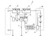
1は本発明に係る充電装置であり、電源Pから供給される直流電流を制御して充電対象の二次電池Bに充電する。
前記二次電池Bは少なくとも1つのセルから構成されており、少なくとも1つのセルの端子電圧が所定の設定電圧になるとアラーム信号ALを出力し、前記二次電池Bの全てのセルの端子電圧が設定電圧未満になった状態でアラーム信号ALを解除するアラーム回路4が、前記二次電池Bと一体に付設されている。EMBODIMENT OF THE INVENTION Below, the form for implementing the charging device which concerns on this invention is demonstrated with reference to drawings.
In FIG.
Reference numeral 1 denotes a charging device according to the present invention, which controls a direct current supplied from a power supply P to charge a secondary battery B to be charged.
The secondary battery B is composed of at least one cell. When the terminal voltage of at least one cell reaches a predetermined set voltage, an alarm signal AL is output, and the terminal voltages of all the cells of the secondary battery B are An
前記充電装置1は、
前記電源Pと前記二次電池Bの間に介在して、充電制御信号S1に基づいた充電電流Iを前記二次電池Bに供給する充電回路2と、
前記充電回路2によって前記二次電池Bに充電される充電電流Iを検出して充電電流検出信号S2として出力する検出回路3と、
前記アラーム信号ALが入力されるまでは、前記充電回路2における充電電流Iを一定電流とする電流制御信号S3を出力し、前記アラーム信号ALが入力されている状態では、前記充電回路2における充電電流Iを所定の下限電流とする電流制御信号S3を出力し、前記アラーム信号ALが解除されると、前記充電回路2における充電電流Iを前記所定の下限電流から漸増させる電流制御信号S3を出力する制御信号生成回路5と、
前記検出回路3から出力される前記充電電流検出信号S2と、前記制御信号生成回路5から出力される電流制御信号S3とを比較して、前記充電電流Iが、前記電流制御信号S3に基づいた電流になるように前記充電制御信号S1を出力する制御回路6と
を備えている。The charging device 1
A charging
A
Until the alarm signal AL is input, a current control signal S3 having a constant charging current I in the charging
The charging current I is based on the current control signal S3 by comparing the charging current detection signal S2 output from the
前記制御信号生成回路5は、図2に示したように、
前記電流制御信号S3を前記アラーム信号ALの状態に基づいて、以下のように切り替えて出力する機能を備えたものである。
すなわち、前記制御信号生成回路5は、
前記アラーム信号ALが入力されるまでは、前記充電回路2における充電電流Iを一定電流とする電流制御信号S3を出力し、
前記アラーム信号ALが入力されている状態では、前記充電回路2における充電電流Iを所定の下限電流(電流0の場合を含む。)とする電流制御信号S3を出力し、
前記アラーム信号ALが解除されると、前記充電回路2における充電電流Iを前記所定の下限電流から漸増させる電流制御信号S3を出力するものである。
なお、充電開始の時点では、二次電池のBの状態に応じて適切な予備充電を行ったあと、前記アラーム信号ALが入力されるまでは、前記一定電流による定電流充電を行う。As shown in FIG. 2, the control
Based on the state of the alarm signal AL, the current control signal S3 is switched and output as follows.
That is, the control
Until the alarm signal AL is input, a current control signal S3 with a constant charging current I in the charging
In a state in which the alarm signal AL is input, a current control signal S3 is output which sets the charging current I in the charging
When the alarm signal AL is canceled, a current control signal S3 for gradually increasing the charging current I in the charging
Note that at the start of charging, after performing appropriate preliminary charging according to the state of the secondary battery B, constant current charging with the constant current is performed until the alarm signal AL is input.
なお、前記アラーム回路4は、セルの端子電圧が規定電圧を瞬時も越えないように、また、できるだけ短時間で満充電とするために、前記二次電池Bの少なくとも1つのセルの端子電圧が所定の設定電圧になると、遅れることなく直ちにアラーム信号ALを出力し、前記二次電池Bの全てのセルの端子電圧が設定電圧未満になると、遅れることなく直ちにアラーム信号ALを解除する必要がある。すなわち、アラーム信号の出力/解除のタイミングが遅れないように、ヒステリシス特性を持たせない必要がある。Incidentally, the
以下に、本発明に係る充電装置の実施例1を、図1〜3を参照して説明する。
実施例1は、充電対象の二次電池をリチウムイオン二次電池(以下、単に「Li-ion電池」と表記する。)とする充電装置である。
Li-ion電池に関しては、電気用品安全法に基づいて、1セルの端子電圧が所定の規定電圧を越えないように、1セル単位で厳密な電池電圧の管理が求められている。したがって、アラーム回路4がアラーム信号ALを出力する設定電圧は、前記規定電圧を越えないように、前記規定電圧未満の値に設定されている。
本実施例1において、充電対象とするLi-ion電池Bは2セル以上の複数のセルで構成されており、さらに、アラーム回路4も一体的に付設されている。したがって、実施例1の充電装置1はアラーム回路4は備えていない。Below, Example 1 of the charging device which concerns on this invention is demonstrated with reference to FIGS.
Example 1 is a charging device in which a secondary battery to be charged is a lithium ion secondary battery (hereinafter simply referred to as “Li-ion battery”).
Regarding Li-ion batteries, based on the Electrical Appliance and Material Safety Law, strict battery voltage management is required for each cell so that the terminal voltage of one cell does not exceed a predetermined specified voltage. Therefore, the set voltage at which the
In the first embodiment, the Li-ion battery B to be charged is composed of a plurality of two or more cells, and an
前記Li-ion電池Bに付設されているアラーム回路4は、
少なくとも何れか1つのセルの端子電圧が前記規定電圧未満の所定の設定電圧になるとアラーム信号ALを出力し、全てのセルの端子電圧が前記設定電圧未満になった状態でアラーム信号ALを解除するように構成されている。
実施例1において、充電回路2、検出回路3、制御信号生成回路5、制御回路6は前述した通りであるので、その説明は省略する。The
When the terminal voltage of at least one cell becomes a predetermined set voltage lower than the specified voltage, an alarm signal AL is output, and the alarm signal AL is canceled when the terminal voltages of all cells are lower than the set voltage. It is configured as follows.
In the first embodiment, since the charging
図1において、
7は、使用者が充電開始を指示するための充電開始スイッチであり、この充電開始スイッチ7がオンされると、制御回路6は、必要に応じて予備充電を行い、そのあと、前記制御信号生成回路5から出力される電流制御信号S3に基づいて定電流充電を開始する。In FIG.
7 is a charging start switch for the user to instruct the start of charging. When this charging
8は、満充電状態を検出したときに、満充電検出信号S4を前記制御回路6へ出力して、充電電流を0として充電を終了するように制御する満充電検出回路である。
前記充電電流検出信号S2が、所定時間以上継続して、所定の基準電流値以下であるときに、前記満充電状態を検出するように構成されている。
When the charging current detection signal S2 continues for a predetermined time or longer and is equal to or lower than a predetermined reference current value, the fully charged state is detected.
なお、前記制御信号生成回路5においては、
定電流充電における一定電流値を設定する定電流設定機能、
下限電流を0もしくは0に近い電流値に設定する下限電流設定機能、および
充電電流を漸増させる特性を設定する漸増電流設定機能を備えている。In the control
Constant current setting function to set a constant current value in constant current charging,
It has a lower limit current setting function for setting the lower limit current to 0 or a current value close to 0, and a gradually increasing current setting function for setting characteristics for gradually increasing the charging current.
以下に、実施例1における前記制御信号生成回路5のより具体的な構成を図3に基づいて説明する。
図3の(A)において、
51は安定して正確な基準電圧Vrefを生成する基準電圧生成回路である。
前記基準電圧Vrefとアースとの間には、第1抵抗R1と第2抵抗R2との直接回路を備え、さらに、前記第2抵抗R2に並列接続されたコンデンサCと、前記コンデンサCに並列接続された開閉手段52とを備えている。
前記開閉手段52は、前記アラーム信号ALが入力されたときには閉じ、前記アラーム信号ALが入力されない状態、および、解除されたときには前記開閉手段52を開くように構成されている。
前記コンデンサCの端子電圧を前記電流制御信号S3として出力するように構成されている。
図3の(B)は、前記開閉手段52が閉じた状態を説明する図であり、
図3の(C)は、前記開閉手段52が開いた状態を説明する図である。Hereinafter, a more specific configuration of the control
In FIG. 3A,
A direct circuit of a first resistor R1 and a second resistor R2 is provided between the reference voltage Vref and the ground, and a capacitor C connected in parallel to the second resistor R2 and a capacitor C connected in parallel. The opening / closing means 52 is provided.
The opening / closing means 52 is configured to close when the alarm signal AL is input, to open the opening / closing means 52 when the alarm signal AL is not input, and when the alarm signal AL is released.
The terminal voltage of the capacitor C is output as the current control signal S3.
FIG. 3B is a diagram illustrating a state in which the opening / closing means 52 is closed.
FIG. 3C is a diagram illustrating a state where the opening / closing means 52 is opened.
前記開閉手段52が閉じた状態では、図3の(B)に示したように、前記第3抵抗R3はアースされることになるので、前記基準電圧Vrefは、前記第1抵抗R1と、第2抵抗R2と第3抵抗R3との並列抵抗(合成抵抗値=R2・R3/(R2+R3))の分圧比で分圧されて前記コンデンサCに印加される。
したがって、前記第3抵抗R3の抵抗値を十分に低くすると、前記コンデンサCに印加される電圧は十分に低い電圧となり、前記電流制御信号S3は充電電流Iを下限電流とすることができる。
また、前記コンデンサCの両端は、前記第2抵抗R2と前記第3抵抗R3との並列抵抗で短絡されることになるので、前記第3抵抗R3の抵抗値を十分に低くすると、前記アラーム信号ALが入力された直後には前記コンデンサCに蓄積された電荷が放電され、前記アラーム信号ALが解除されたときには、後述するように、前記コンデンサCの端子電圧は下限値から漸増する。When the opening / closing means 52 is closed, as shown in FIG. 3B, the third resistor R3 is grounded, so that the reference voltage Vref is the first resistor R1 and the first resistor R1. The two resistors R2 and the third resistor R3 are divided by a voltage dividing ratio of a parallel resistance (combined resistance value = R2 / R3 / (R2 + R3)) and applied to the capacitor C.
Accordingly, when the resistance value of the third resistor R3 is sufficiently low, the voltage applied to the capacitor C is sufficiently low, and the current control signal S3 can set the charging current I as the lower limit current.
In addition, since both ends of the capacitor C are short-circuited by a parallel resistance of the second resistor R2 and the third resistor R3, if the resistance value of the third resistor R3 is sufficiently low, the alarm signal Immediately after AL is input, the charge accumulated in the capacitor C is discharged, and when the alarm signal AL is canceled, the terminal voltage of the capacitor C gradually increases from the lower limit value, as will be described later.
前記開閉手段52が開いた状態では、図3の(C)に示したように、前記基準電圧は、前記第1抵抗R1と第2抵抗R2との分圧比で分圧されて前記コンデンサCに印加される。
したがって、前記開閉手段52が閉じた状態から開いた状態に変化した直後は、第1抵抗R1とコンデンサCとによって時定数回路が構成され、前記コンデンサCの端子電圧、すなわち、前記電流制御信号S3は、前記時定数回路で規定される漸増特性に基づいて漸増する。第1抵抗R1とコンデンサCの値は、前記コンデンサCの端子電圧に基づいた電流制御信号S3が、所定の漸増特性で漸増するように設定されている。When the opening / closing means 52 is opened, the reference voltage is divided by the voltage dividing ratio of the first resistor R1 and the second resistor R2 to the capacitor C as shown in FIG. Applied.
Accordingly, immediately after the opening / closing means 52 changes from the closed state to the open state, the first resistor R1 and the capacitor C form a time constant circuit, and the terminal voltage of the capacitor C, that is, the current control signal S3. Gradually increases based on a gradually increasing characteristic defined by the time constant circuit. The values of the first resistor R1 and the capacitor C are set so that the current control signal S3 based on the terminal voltage of the capacitor C gradually increases with a predetermined gradually increasing characteristic.
前記コンデンサCの端子電圧が前記分圧された電圧に到達したあとは、前記コンデンサCの端子電圧、すなわち、前記電流制御信号S3は一定の状態で持続する。
前記第1抵抗R1と第2抵抗R2との分圧比は、前記分圧された電圧に基づいた電流制御信号S3が、前記定電流充電における電流値を所定の電流値とするように設定されている。After the terminal voltage of the capacitor C reaches the divided voltage, the terminal voltage of the capacitor C, that is, the current control signal S3 is maintained in a constant state.
The voltage dividing ratio between the first resistor R1 and the second resistor R2 is set so that the current control signal S3 based on the divided voltage has a current value in the constant current charging as a predetermined current value. Yes.
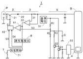
図4は、前記実施例1の詳細な回路を示したものである。
図4において、
充電回路2は、充電電流を制御するための第1トランジスタ21と、逆流防止ダイオード22とを備えている。
検出回路3は、前記充電電流による電圧降下を検出するための低抵抗31と、前記低抵抗31の両端の電圧を検出して充電電流検出信号S2として出力するアンプ32とを備えている。
制御信号生成回路5は、
図3における開閉手段52に代わる開閉手段としての第2トランジスタQ2と、
Li-ion電池Bに付設されたアラーム回路4から出力されるアラーム信号ALを2値化するためのリセット回路55と、
前記リセット回路55の出力の極性を前記第2トランジスタQ2の入力に適合させるための論理反転回路を構成する第3トランジスタQ3と、
図3と同様の抵抗R1,R2,R3,コンデンサCを備えている。FIG. 4 shows a detailed circuit of the first embodiment.
In FIG.
The charging
The
The control
A second transistor Q2 as an opening / closing means instead of the opening / closing means 52 in FIG. 3;
A
A third transistor Q3 constituting a logic inverting circuit for adapting the polarity of the output of the
Resistors R1, R2, R3 and a capacitor C similar to those in FIG.
前記制御回路6は、前記充電電流検出信号S2と前記充電電流制御信号S3とが入力され、充電制御信号S1を出力する比較増幅器61と、充電制御信号出力回路62とを備えている。
前記充電制御信号出力回路62には、前記充電制御信号S1、満充電検出信号S4、充電開始信号S5が入力され、前記充電回路2に対する前記充電制御信号S1を出力するとともに、前記満充電検出信号S4に基づいて充電電流を0とし、前記充電開始信号S5に基づいて充電開始するように構成されている。The
The charge control
次に、上記実施例1の充電装置における、Li-ion電池に対する充電過程を、図5を参照して説明する。
図5の(A)は、前記Li-ion電池Bに印加される充電電圧の変化を示したものであり、
図5の(B)は、前記Li-ion電池Bに供給される充電電流の変化を示したものであり、
図5の(C)は、前記Li-ion電池Bのアラーム回路4から出力されるアラーム信号ALの状態を示したものである。Next, a charging process for the Li-ion battery in the charging device of the first embodiment will be described with reference to FIG.
FIG. 5A shows a change in the charging voltage applied to the Li-ion battery B.
FIG. 5B shows a change in charging current supplied to the Li-ion battery B.
5C shows the state of the alarm signal AL output from the
充電開始スイッチ7がオンされると、充電開始回路71においては、Li-ion電池Bのセット状態、Li-ion電池Bの端子電圧、電源の状態等の充電開始条件をチェックして、これらの充電開始条件が全て満足した場合に、充電開始信号S5を出力して充電を開始する。
充電初期では、予備充電を行い、その後、定電流充電に移行する。この場合には、図5の(A)に示したように、前記Li-ion電池Bの電圧は低いため、アラーム信号ALは出力されていないので、前記制御信号生成回路5からは、充電電流を所定の一定電流(たとえば、1A)とするための電流制御信号S3が出力される。
図5の(B)に示した過程1のように、一定電流による定電流充電が進行することにより、図5の(A)に示した過程1のように、Li-ion電池Bの電圧は漸増する。この状態では、図5の(C)の過程1に示したように、アラーム信号ALは出力されていない。When the
In the initial stage of charging, preliminary charging is performed, and thereafter, constant current charging is performed. In this case, as shown in FIG. 5A, since the voltage of the Li-ion battery B is low, the alarm signal AL is not output. A current control signal S3 for outputting a predetermined constant current (for example, 1 A) is output.
As shown in the process 1 shown in FIG. 5B, the constant current charging with a constant current proceeds, so that the voltage of the Li-ion battery B is changed as shown in the process 1 shown in FIG. Increase gradually. In this state, the alarm signal AL is not output as shown in the process 1 of FIG.
図5の(A)の過程2に示したように、Li-ion電池Bのセルの電圧が設定電圧になると、図5の(C)の過程2に示したように、アラーム回路4からアラーム信号ALが出力される。この場合のアラーム信号ALは、ローレベルのときに、セルの電圧が設定電圧になったことを示し、ハイレベルのときに、セルの電圧が設定電圧未満であることを示す仕様となっている。これに加え、規定の環境温度(例えば、45°C)以上において設定電圧(例えば、4.25V/セルより低い電圧)に達した時は、ハイレベル×1/2レベルのアラーム信号ALが出力される。 As shown in
アラーム信号ALが出力されると、
図3の開閉手段52は閉じられ、図4のトランジスタQ2はオンとなるので、
制御信号生成回路5から出力される電流制御信号S3は、充電電流が所定の下限電流となるような電流制御信号S3となり、図5の(B)の過程2に示したように、充電電流Iは一端、所定の下限電流に制御される。When the alarm signal AL is output,
3 is closed, and the transistor Q2 in FIG. 4 is turned on.
The current control signal S3 output from the control
その後、図5の(A)の過程3に示したように、Li-ion電池Bのセルの電圧が設定電圧未満に低下すると、図5の(C)の過程3に示したように、アラーム信号ALは解除される。
出力されていたアラーム信号ALが解除されると、
図3の開閉手段52は開かれ、図4のトランジスタQ2はオフとなるので、
制御信号生成回路5から出力される電流制御信号S3は、コンデンサCの端子電圧の上昇に応じて漸増する電流制御信号S3となるので、図5の(B)の過程3に示したように、充電電流Iは漸増するように制御される。Thereafter, when the voltage of the cell of the Li-ion battery B falls below the set voltage as shown in
When the output alarm signal AL is canceled,
3 is opened, and the transistor Q2 in FIG. 4 is turned off.
Since the current control signal S3 output from the control
ここで、再び、図5の(A)の過程4に示したように、Li-ion電池Bのセルの電圧が設定電圧になると、図5の(C)の過程4に示したように、アラーム回路4からアラーム信号ALが出力され、図5の(B)の過程2に示したように、充電電流Iは一端、所定の下限電流に制御される。 Here, again, as shown in the
ここで、再び、図5の(A)の過程5に示したように、Li-ion電池Bのセルの電圧が設定電圧未満になると、図5の(C)の過程5に示したように、アラーム信号ALが解除され、図5の(B)の過程5に示したように、充電電流Iは漸増するように制御される。 Here, again, as shown in the
以上のように、Li-ion電池Bの端子電圧が上昇して設定電圧に到達するたびに、アラーム信号ALが出力されて、充電電流が一端、下限電流に下げられ、そのあと、Li-ion電池Bの端子電圧が設定電圧未満に下がると、アラーム信号ALが解除されて、漸増する充電電流で充電される。という過程が、満充電状態が検出されるまで繰り返される。 As described above, every time the terminal voltage of the Li-ion battery B rises and reaches the set voltage, the alarm signal AL is output, the charging current is reduced to the lower limit current, and then the Li-ion When the terminal voltage of the battery B drops below the set voltage, the alarm signal AL is canceled and the battery B is charged with a gradually increasing charging current. This process is repeated until a fully charged state is detected.
なお、前記充電電流Iが、所定時間(たとえば、180msec)以上継続して、所定の基準電流値流(たとえば、33mA)以下であるときに満充電を検出する。 Full charge is detected when the charging current I continues for a predetermined time (for example, 180 msec) or longer and is equal to or lower than a predetermined reference current value flow (for example, 33 mA).
以上のようにして、本発明に係る充電装置によれば、
各セルの端子電圧を常に監視して、各セルの何れか、または、全てが設定電圧に達すると充電電流を下限電流に下げて、全てのセルの電圧が設定電圧未満になると、充電電流を下限電流から緩やかに上昇させるような漸増電流によって充電することを繰り返すので、従来の定電流によるパルス充電方式のようにセルの電圧が設定電圧を越える危険を完全に防止することができる。
また、環境温度によって満充電電圧を変えたいときにおいても、アラーム信号ALに対し、リセット回路55で2値化を行い、充電電流の制御を行うので、環境温度に適した充電電圧の設定が可能となる。したがって、前記設定電圧を、規定電圧ぎりぎりの高い電圧に設定することができるので、Li-ion電池の容量を最大限利用することができる。
また、定電流充電を行っているため定電圧充電に比べて充電時間を短縮することができる。As described above, according to the charging device of the present invention,
The terminal voltage of each cell is constantly monitored, and when any or all of the cells reach the set voltage, the charging current is lowered to the lower limit current, and when the voltage of all cells falls below the set voltage, the charging current is reduced. Since charging is repeatedly performed with a gradually increasing current that gradually increases from the lower limit current, it is possible to completely prevent the risk that the cell voltage exceeds the set voltage as in the conventional pulse charging method using a constant current.
In addition, even when it is desired to change the full charge voltage depending on the environmental temperature, the alarm signal AL is binarized by the
Moreover, since constant current charging is performed, the charging time can be shortened compared to constant voltage charging.
なお、前記制御信号生成回路5は、実施例1で示したように、RC直列回路による時定数回路を用いて漸増する充電電流制御信号S3を生成して出力するように構成したが、漸増する充電電流制御信号S3を生成して出力するものであれば、RC直列回路による時定数回路に限定されるものでないことは当然である。
たとえば、種々の波形生成回路を用いることができ、アナログ回路に限らず、デジタル回路もしくはソフトウエアによって漸増する充電電流制御信号S3を生成して出力してもよい。
The control
For example, various waveform generation circuits can be used, and not only an analog circuit but also a charging current control signal S3 that gradually increases by a digital circuit or software may be generated and output.
本発明にかかる充電装置は、Li-ion電池に限らず、種々の二次電池を対象とする充電装置に利用することができる。
The charging device according to the present invention is not limited to a Li-ion battery, and can be used for a charging device for various secondary batteries.
B 二次電池、Li-ion電池
P 電源
1 充電装置
2 充電回路
3 検出回路
4 アラーム回路
5 制御信号生成回路
52 開閉手段
Q2 第2トランジスタ
R1 第1抵抗
R2 第2抵抗
R3 第3抵抗
C コンデンサ
6 制御回路
I 充電電流
S1 充電制御信号
S2 充電電流検出信号
S3 電流制御信号
S4 満充電検出信号
S5 充電開始信号
AL アラーム信号B Secondary battery, Li-ion battery P Power source 1
Claims (4)
Translated fromJapanese前記電源と前記二次電池の間に介在して、電流制御信号に基づいた充電電流を前記二次電池に供給する充電回路と、
前記充電回路によって前記二次電池に供給される充電電流を検出する検出回路と、
前記二次電池の少なくとも1つのセルの端子電圧が所定の設定電圧になったときにアラーム信号を出力し、前記二次電池の全てのセルの端子電圧が設定電圧未満になったときに前記アラーム信号を解除するアラーム回路と、
前記アラーム信号が入力されるまでは、前記充電回路における充電電流を所定の一定電流とする電流制御信号を出力し、前記アラーム信号が入力されている状態では、前記充電回路における充電電流を所定の下限電流とする電流制御信号を出力し、前記アラーム信号が解除されると、前記充電回路における充電電流を、前記所定の下限電流から漸増させる電流制御信号を出力する制御信号生成回路と、
前記検出回路で検出した充電電流が、前記電流制御信号に基づいた電流に一致するように前記充電回路を制御するための充電制御信号を出力する制御回路と、
前記充電電流が、所定の基準時間以上の間、継続して所定の基準電流値以下の状態のときに、満充電状態を検出し、前記充電回路における充電電流をゼロとする電流制御信号を出力する満充電検出回路とを備えていることを特徴とする充電装置。In the charging device for charging the secondary battery to be charged by controlling the direct current supplied from a power source,
A charging circuit that is interposed between the power source and the secondary battery and supplies a charging current based on a current control signal to the secondary battery;
A detection circuit for detecting a charging current supplied to the secondary battery by the charging circuit;
An alarm signal is output when a terminal voltage of at least one cell of the secondary battery reaches a predetermined set voltage, and the alarm signal is output when the terminal voltage of all cells of the secondary battery becomes less than a set voltage. An alarm circuit to release the signal,
Until the alarm signal is input, a current control signal for setting the charging current in the charging circuit to a predetermined constant current is output. In the state where the alarm signal is input, the charging current in the charging circuit is set to a predetermined value. A control signal generation circuit that outputs a current control signal that outputs a current control signal that is a lower limit current and that gradually increases the charging current in the charging circuit from the predetermined lower limit current when the alarm signal is canceled;
A control circuit that outputs a charging control signal for controlling the charging circuit so that a charging current detected by the detection circuit matches a current based on the current control signal;
When the charging current is continuously below a predetermined reference current value for a predetermined reference time or longer, a fully charged state is detected and a current control signal for zeroing the charging current in the charging circuit is output. And a full-charge detection circuit .
前記電源と前記二次電池の間に介在して、電流制御信号に基づいた充電電流を前記二次電池に供給する充電回路と、
前記充電回路によって前記二次電池に供給される充電電流を検出する検出回路と、
前記アラーム信号が入力されるまでは、前記充電回路における充電電流を所定の一定電流とする電流制御信号を出力し、前記アラーム信号が入力されている状態では、前記充電回路における充電電流を所定の下限電流とする電流制御信号を出力し、前記アラーム信号が解除されると、前記充電回路における充電電流を、前記所定の下限電流から漸増させる電流制御信号を出力する制御信号生成回路と、
前記検出回路で検出した充電電流が、前記電流制御信号に基づいた電流に一致するように前記充電回路を制御するための充電制御信号を出力する制御回路と、
前記充電電流が、所定の基準時間以上の間、継続して所定の基準電流値以下の状態のときに、満充電状態を検出し、前記充電回路における充電電流をゼロとする電流制御信号を出力する満充電検出回路とを備えていることを特徴とする充電装置。A charging device for charging a secondary battery composed of at least one cell, outputs an alarm signal when a terminal voltage of at least one cell reaches a predetermined set voltage, and all of the secondary batteries In a charging device for controlling and charging a direct current supplied from a power supply to a secondary battery to which an alarm circuit for canceling the alarm signal is added when the terminal voltage of the cell becomes lower than a set voltage ,
A charging circuit that is interposed between the power source and the secondary battery and supplies a charging current based on a current control signal to the secondary battery;
A detection circuit for detecting a charging current supplied to the secondary battery by the charging circuit;
Until the alarm signal is input, a current control signal for setting the charging current in the charging circuit to a predetermined constant current is output. In the state where the alarm signal is input, the charging current in the charging circuit is set to a predetermined value. A control signal generation circuit that outputs a current control signal that outputs a current control signal that is a lower limit current and that gradually increases the charging current in the charging circuit from the predetermined lower limit current when the alarm signal is canceled;
A control circuit that outputs a charging control signal for controlling the charging circuit so that a charging current detected by the detection circuit matches a current based on the current control signal;
When the charging current is continuously below a predetermined reference current value for a predetermined reference time or longer, a fully charged state is detected and a current control signal for zeroing the charging current in the charging circuit is output. And a full-charge detection circuit .
所定の電圧が印加された第1抵抗と第2抵抗との直列回路と、
前記第2抵抗に並列接続されたコンデンサと、
前記コンデンサに並列接続された開閉手段とを備え、
前記アラーム信号が入力されたときには前記開閉手段を閉じ、
前記アラーム信号が入力されない状態、および、解除されたときには前記開閉手段を開くように制御され、
前記コンデンサの端子電圧を前記電流制御信号として出力するように構成されていることを特徴とする請求項1または2記載の充電装置。The control signal generation circuit includes:
A series circuit of a first resistor and a second resistor to which a predetermined voltage is applied;
A capacitor connected in parallel to the second resistor;
Opening and closing means connected in parallel to the capacitor,
When the alarm signal is input, the opening / closing means is closed,
When the alarm signal is not input, and when the alarm signal is canceled, the opening / closing means is controlled to open,
Charging apparatus according to claim 1 or2 Symbol mounting, characterized in that it is configured to output a terminal voltage of the capacitor as the current control signal.
コレクタが第3の抵抗を介して前記コンデンサの一端に接続され、エミッタが前記コンデンサの他端に接続されたトランジスタを含み、
前記トランジスタのベースには前記アラーム信号が入力されるように構成されていることを特徴とする請求項3記載の充電装置。The opening / closing means includes
Including a transistor having a collector connected to one end of the capacitor via a third resistor and an emitter connected to the other end of the capacitor;
3. Symbol placing the charging device, characterized in that it is configured such that the alarm signal is input to the base of said transistor.
Priority Applications (1)
| Application Number | Priority Date | Filing Date | Title |
|---|---|---|---|
| JP2011145936AJP5810681B2 (en) | 2011-06-30 | 2011-06-30 | Charger |
Applications Claiming Priority (1)
| Application Number | Priority Date | Filing Date | Title |
|---|---|---|---|
| JP2011145936AJP5810681B2 (en) | 2011-06-30 | 2011-06-30 | Charger |
Publications (2)
| Publication Number | Publication Date |
|---|---|
| JP2013013294A JP2013013294A (en) | 2013-01-17 |
| JP5810681B2true JP5810681B2 (en) | 2015-11-11 |
Family
ID=47686649
Family Applications (1)
| Application Number | Title | Priority Date | Filing Date |
|---|---|---|---|
| JP2011145936AActiveJP5810681B2 (en) | 2011-06-30 | 2011-06-30 | Charger |
Country Status (1)
| Country | Link |
|---|---|
| JP (1) | JP5810681B2 (en) |
Families Citing this family (2)
| Publication number | Priority date | Publication date | Assignee | Title |
|---|---|---|---|---|
| JP2018007488A (en)* | 2016-07-06 | 2018-01-11 | 株式会社リコー | Charging device and image forming apparatus |
| CN111404238B (en)* | 2020-04-28 | 2024-12-10 | 上海电力大学 | A lithium battery pack charging device |
Family Cites Families (4)
| Publication number | Priority date | Publication date | Assignee | Title |
|---|---|---|---|---|
| US5550453A (en)* | 1994-01-24 | 1996-08-27 | Motorola, Inc. | Battery charging method and apparatus |
| JP3435862B2 (en)* | 1994-12-14 | 2003-08-11 | 松下電工株式会社 | Charging device |
| JP3005460B2 (en)* | 1995-04-18 | 2000-01-31 | 三洋電機株式会社 | Rechargeable battery charging method |
| JP5506498B2 (en)* | 2010-03-30 | 2014-05-28 | パナソニック株式会社 | Secondary battery charging device and charging method |
- 2011
- 2011-06-30JPJP2011145936Apatent/JP5810681B2/enactiveActive
Also Published As
| Publication number | Publication date |
|---|---|
| JP2013013294A (en) | 2013-01-17 |
Similar Documents
| Publication | Publication Date | Title |
|---|---|---|
| JP5324483B2 (en) | Multi-cell battery pack protection circuit | |
| KR0173961B1 (en) | Mode conversion type battery charging apparatus | |
| US7816889B2 (en) | Method of charging rechargeable battery and protection circuit for rechargeable battery | |
| JP5289083B2 (en) | Secondary battery abnormality detection device and secondary battery device | |
| CN1998110B (en) | Lithium-ion/polymer lithium battery cell charging method | |
| US8299755B2 (en) | Battery balance charging controller for making one battery having lower voltage out of batteries connected in series to receive greater charging current and battery charging controlling apparatus using the same | |
| KR101696160B1 (en) | Apparatus, system and method for preventing damage of battery rack using voltage measurement | |
| WO2011074390A1 (en) | Battery module control system, and battery module control method | |
| JP6196466B2 (en) | Power supply | |
| JP2009232559A (en) | Battery pack charging balancing circuit | |
| KR102349705B1 (en) | Battery cell balancing circuit and apparatus and method for balancing of a battery cell for using the same | |
| JP2005052000A5 (en) | ||
| TW201830823A (en) | Control device, balance correction device, electric storage system and apparatus | |
| CN104977540A (en) | Method for monitoring a charge state or a charge or discharge current of a rechargeable battery | |
| JP6370137B2 (en) | Charge / discharge control circuit and battery device | |
| KR101264428B1 (en) | Battery Pack | |
| JP2015204705A (en) | Charge control circuit and method, and charging device | |
| JPH097641A (en) | Charging method of secondary battery | |
| JP2017209003A (en) | Method and apparatus for charging vehicle battery | |
| JP5810681B2 (en) | Charger | |
| JP2002369399A (en) | Battery state adjustment device | |
| KR100349723B1 (en) | a device for discharging a lithum ion battery | |
| US20180145524A1 (en) | Battery charging circuit and charging method thereof | |
| WO2013089113A1 (en) | Power storage device and charging/discharging method | |
| JP2015035924A (en) | Overcurrent protective device |
Legal Events
| Date | Code | Title | Description |
|---|---|---|---|
| A621 | Written request for application examination | Free format text:JAPANESE INTERMEDIATE CODE: A621 Effective date:20140521 | |
| A977 | Report on retrieval | Free format text:JAPANESE INTERMEDIATE CODE: A971007 Effective date:20150113 | |
| A131 | Notification of reasons for refusal | Free format text:JAPANESE INTERMEDIATE CODE: A131 Effective date:20150120 | |
| A521 | Request for written amendment filed | Free format text:JAPANESE INTERMEDIATE CODE: A523 Effective date:20150303 | |
| TRDD | Decision of grant or rejection written | ||
| A01 | Written decision to grant a patent or to grant a registration (utility model) | Free format text:JAPANESE INTERMEDIATE CODE: A01 Effective date:20150818 | |
| A61 | First payment of annual fees (during grant procedure) | Free format text:JAPANESE INTERMEDIATE CODE: A61 Effective date:20150831 | |
| R150 | Certificate of patent or registration of utility model | Ref document number:5810681 Country of ref document:JP Free format text:JAPANESE INTERMEDIATE CODE: R150 | |
| R250 | Receipt of annual fees | Free format text:JAPANESE INTERMEDIATE CODE: R250 | |
| R250 | Receipt of annual fees | Free format text:JAPANESE INTERMEDIATE CODE: R250 | |
| R250 | Receipt of annual fees | Free format text:JAPANESE INTERMEDIATE CODE: R250 | |
| R250 | Receipt of annual fees | Free format text:JAPANESE INTERMEDIATE CODE: R250 | |
| R250 | Receipt of annual fees | Free format text:JAPANESE INTERMEDIATE CODE: R250 | |
| R250 | Receipt of annual fees | Free format text:JAPANESE INTERMEDIATE CODE: R250 | |
| R250 | Receipt of annual fees | Free format text:JAPANESE INTERMEDIATE CODE: R250 | |
| R250 | Receipt of annual fees | Free format text:JAPANESE INTERMEDIATE CODE: R250 |