JP5810049B2 - Image forming apparatus and image forming system - Google Patents
Image forming apparatus and image forming systemDownload PDFInfo
- Publication number
- JP5810049B2 JP5810049B2JP2012176914AJP2012176914AJP5810049B2JP 5810049 B2JP5810049 B2JP 5810049B2JP 2012176914 AJP2012176914 AJP 2012176914AJP 2012176914 AJP2012176914 AJP 2012176914AJP 5810049 B2JP5810049 B2JP 5810049B2
- Authority
- JP
- Japan
- Prior art keywords
- image
- unit
- frame line
- display unit
- displayed
- Prior art date
- Legal status (The legal status is an assumption and is not a legal conclusion. Google has not performed a legal analysis and makes no representation as to the accuracy of the status listed.)
- Expired - Fee Related
Links
Images


Classifications
- H—ELECTRICITY
- H04—ELECTRIC COMMUNICATION TECHNIQUE
- H04N—PICTORIAL COMMUNICATION, e.g. TELEVISION
- H04N1/00—Scanning, transmission or reproduction of documents or the like, e.g. facsimile transmission; Details thereof
- H04N1/0035—User-machine interface; Control console
- H04N1/00352—Input means
- H04N1/00392—Other manual input means, e.g. digitisers or writing tablets
- H—ELECTRICITY
- H04—ELECTRIC COMMUNICATION TECHNIQUE
- H04N—PICTORIAL COMMUNICATION, e.g. TELEVISION
- H04N1/00—Scanning, transmission or reproduction of documents or the like, e.g. facsimile transmission; Details thereof
- H04N1/0035—User-machine interface; Control console
- H04N1/00405—Output means
- H04N1/00408—Display of information to the user, e.g. menus
- H04N1/0044—Display of information to the user, e.g. menus for image preview or review, e.g. to help the user position a sheet
Landscapes
- Engineering & Computer Science (AREA)
- Multimedia (AREA)
- Signal Processing (AREA)
- Human Computer Interaction (AREA)
- Record Information Processing For Printing (AREA)
- Facsimiles In General (AREA)
- Editing Of Facsimile Originals (AREA)
- Accessory Devices And Overall Control Thereof (AREA)
- Control Or Security For Electrophotography (AREA)
- Image Processing (AREA)
- User Interface Of Digital Computer (AREA)
Description
Translated fromJapanese本発明は、画像形成装置及び画像形成システムに関する。 The present invention relates to an image forming apparatus and an image forming system.
従来から、原稿読取部で読み取った原稿の画像(原稿画像)を表示部にプレビュー表示する機能を持った画像形成装置が知られている。例えば、下記特許文献1には、表示部にプレビュー表示された原稿画像上で2点を指定する操作が為された場合に、その2点を対角線とする矩形領域を印刷すべき画像領域(トリミング領域)として認識する機能を持った画像形成装置が開示されている。 2. Description of the Related Art Conventionally, an image forming apparatus having a function of displaying a preview image (original image) of a document read by a document reading unit on a display unit is known. For example, in
上記従来技術では、ユーザーは、トリミング領域を設定するために、タッチパネル付きの表示部に表示された第1点指定ボタンを押してから、プレビュー表示中の原稿画像上の第1点を指定する操作を行い、その次に、同じく表示部に表示された第2点指定ボタンを押してから原稿画像上の第2点を指定する操作を行うなど、煩雑な操作が必要であった。 In the above prior art, in order to set the trimming region, the user presses the first point designation button displayed on the display unit with the touch panel, and then performs an operation of designating the first point on the document image being displayed in preview. Next, a complicated operation such as pressing the second point designation button also displayed on the display unit and then designating the second point on the document image is necessary.
本発明は上述した事情に鑑みてなされたものであり、ユーザーがトリミングという作業を意識せずに、容易な操作で意図する印刷領域(印刷すべき画像領域)を指定することが可能な画像形成装置及び画像形成システムを提供することを目的とする。 The present invention has been made in view of the above-described circumstances, and image formation that allows a user to designate an intended print area (image area to be printed) with an easy operation without being aware of the work of trimming. An object is to provide an apparatus and an image forming system.
上記課題を解決するために、本発明では、画像形成装置に係る第1の解決手段として、所定の画像を表示する表示部と、前記表示部の表示画面上で為された操作に応じた操作信号を出力する操作部と、原稿を読み取って原稿画像を示す原稿画像データを生成する原稿読取部と、印刷用紙に画像を印刷して印刷物として出力する印刷部と、前記原稿画像データを基に前記表示部の表示画面上に前記原稿画像をプレビュー表示させると共に各種サイズの印刷用紙を示すアイコンを表示させ、前記操作信号を基に前記原稿画像上への前記アイコンの移動操作を検知した場合、そのアイコンが示す印刷用紙のサイズに応じた枠線を前記原稿画像に重ねて表示させて前記枠線で囲まれた領域を印刷領域として認識し、印刷指示を受けた場合には前記印刷領域の画像が、移動操作されたアイコンが示す印刷用紙に印刷されるように前記印刷部を制御する制御部とを備える、という手段を採用する。 In order to solve the above-described problem, in the present invention, as a first solving means related to an image forming apparatus, a display unit that displays a predetermined image, and an operation corresponding to an operation performed on the display screen of the display unit Based on the original image data, an operation unit that outputs a signal, an original reading unit that reads an original and generates original image data indicating an original image, a printing unit that prints an image on a print sheet and outputs the printed image When the original image is previewed on the display screen of the display unit and icons indicating printing papers of various sizes are displayed, and a movement operation of the icon on the original image is detected based on the operation signal, A frame line corresponding to the size of the print paper indicated by the icon is displayed on the original image so that the area surrounded by the frame line is recognized as a print area. Image frequency region, and a control unit for controlling the printing unit to be printed on the printing paper showing the movement operated icon, to adopt a means of.
また、本発明では、画像形成装置に係る第2の解決手段として、上記第1の解決手段において、前記制御部は、前記操作信号を基に前記表示部の表示画面上において前記原稿画像に重ねて表示された前記枠線の移動操作を検知した場合、その移動操作に応じて前記枠線が移動するように前記表示部を制御する、という手段を採用する。 According to the present invention, as the second solving means relating to the image forming apparatus, in the first solving means, the control unit superimposes the original image on the display screen of the display unit based on the operation signal. When the movement operation of the displayed frame line is detected, the display unit is controlled so that the frame line moves according to the movement operation.
また、本発明では、画像形成装置に係る第3の解決手段として、上記第1または第2の解決手段において、前記制御部は、前記操作信号を基に前記表示部の表示画面上において前記原稿画像に重ねて表示された前記枠線の拡大操作或いは縮小操作を検知した場合、その拡大操作或いは縮小操作に応じて前記枠線が拡大或いは縮小するように前記表示部を制御する、という手段を採用する。 According to the present invention, as the third solving means relating to the image forming apparatus, in the first or second solving means, the control unit is configured to display the original on the display screen of the display unit based on the operation signal. Means for controlling the display unit so that the frame line is enlarged or reduced according to the enlargement operation or the reduction operation when an enlargement operation or a reduction operation of the frame line displayed on the image is detected. adopt.
また、本発明では、画像形成装置に係る第4の解決手段として、上記第1〜第3のいずれかの解決手段において、前記制御部は、前記操作信号を基に前記表示部の表示画面上において前記原稿画像に重ねて表示された前記枠線の回転操作を検知した場合、その回転操作に応じて前記枠線が回転するように前記表示部を制御する、という手段を採用する。 According to the present invention, as a fourth solving means relating to the image forming apparatus, in any one of the first to third solving means, the control unit is arranged on a display screen of the display unit based on the operation signal. When the rotation operation of the frame line displayed on the document image is detected, the display unit is controlled so that the frame line is rotated according to the rotation operation.
また、本発明では、画像形成装置に係る第5の解決手段として、上記第1〜第4のいずれかの解決手段において、前記操作部は、前記表示部の表示画面に対向配置されたタッチパネルであり、前記操作信号としてユーザーに押下された部位の座標を示す信号を出力する、という手段を採用する。 According to the present invention, as a fifth solving means related to the image forming apparatus, in any one of the first to fourth solving means, the operation unit is a touch panel disposed opposite to the display screen of the display unit. There is adopted means for outputting a signal indicating the coordinates of the part pressed by the user as the operation signal.
また、本発明では、画像形成システムに係る第1の解決手段として、印刷用紙に画像を印刷して印刷物として出力する画像形成装置と、前記画像形成装置に印刷指示を出力するホスト装置と、前記ホスト装置と前記画像形成装置とを相互接続する通信回線と、を備え、前記ホスト装置は、所定の画像を表示する表示部と、前記表示部の表示画面上で為された操作に応じた操作信号を出力する操作部と、印刷すべき画像の画像データを記憶する記憶部と、前記画像データを基に前記表示部の表示画面上に前記画像をプレビュー表示させると共に各種サイズの印刷用紙を示すアイコンを表示させ、前記操作信号を基に前記画像上への前記アイコンの移動操作を検知した場合、そのアイコンが示す印刷用紙のサイズに応じた枠線を前記画像に重ねて表示させて前記枠線で囲まれた領域を印刷領域として認識し、前記印刷領域の画像が、移動操作されたアイコンが示す印刷用紙に印刷されるように前記印刷指示を出力する制御部と、を備える、という手段を採用する。 In the present invention, as a first solving means related to the image forming system, an image forming apparatus that prints an image on a printing paper and outputs the image as a printed material, a host apparatus that outputs a print instruction to the image forming apparatus, A communication line interconnecting the host device and the image forming apparatus, the host device displaying a predetermined image, and an operation corresponding to an operation performed on the display screen of the display unit An operation unit that outputs a signal, a storage unit that stores image data of an image to be printed, a preview display of the image on the display screen of the display unit based on the image data, and various types of printing paper When an icon is displayed and a movement operation of the icon on the image is detected based on the operation signal, a frame line corresponding to the size of the printing paper indicated by the icon is overlaid on the image. A control unit that recognizes an area surrounded by the border line as a print area and outputs the print instruction so that an image of the print area is printed on a print sheet indicated by the moved icon; The means of providing is adopted.
本発明によれば、ユーザーは、表示部の表示画面上において、所望の印刷用紙のサイズを示すアイコンを、プレビュー表示された原稿画像上へ移動操作するだけで、容易且つ直感的に印刷領域を指定することができる。つまり、本発明によれば、ユーザーがトリミングという作業を意識せずに、容易な操作で意図する印刷領域を指定することが可能となる。 According to the present invention, the user can easily and intuitively set the print area on the display screen of the display unit by simply moving the icon indicating the desired print paper size onto the document image displayed in the preview. Can be specified. In other words, according to the present invention, it is possible to designate an intended print area with a simple operation without the user being aware of the work of trimming.
(第1実施形態)
以下、図面を参照しながら、本発明の一実施形態について説明する。なお、以下では、本発明に係る画像形成装置として、コピー機、プリンター及びファクシミリ等の機能を併せ持つ複合機を例示して説明する。
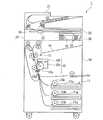
図1は、本実施形態に係る複合機1の要部構成を示す正面透視図である。図2は、複合機1の機能ブロック図である。これらの図に示すように、複合機1は、印刷部10と、原稿読取部20と、GUI(Graphical User Interface)30と、通信部40と、制御部50とを備えている。(First embodiment)
Hereinafter, an embodiment of the present invention will be described with reference to the drawings. Hereinafter, as an image forming apparatus according to the present invention, a multifunction machine having functions such as a copier, a printer, and a facsimile will be described as an example.
FIG. 1 is a front perspective view illustrating a configuration of a main part of a
印刷部10は、制御部50による制御の下、印刷用紙に画像を印刷して印刷物として出力するものであり、給紙部11、トナー画像形成部12、定着部13及び排紙トレイ14等を備えている。給紙部11は、定型の印刷用紙を複数枚(例えば、数十枚程度)収容可能であると共に、複合機1の正面から引出し可能な給紙カセット11aを複数備えている。給紙カセット11aの各々に収容された印刷用紙のうちの最上位の印刷用紙は、ピックアップローラー11bの駆動によって繰り出されてトナー画像形成部12へ搬送される。 The
トナー画像形成部12は、印刷すべき画像に応じたトナー画像を印刷用紙に形成するものであり、感光体ドラム12a、露光部12b、現像部12c及び転写部12d等を備えている。感光体ドラム12aは、印刷すべき画像に応じた静電潜像が形成されると共に、現像されたトナー画像を担持する円筒形の感光体である。露光部12bは、感光体ドラム12aの表面に静電潜像を形成するためのレーザー光を感光体ドラム12aに照射する。
現像部12cは、静電潜像が形成された感光体ドラム12aにトナーを供給することにより、静電潜像を現像してトナー画像にする。転写部12dは、感光体ドラム12aに担持されているトナー画像を、給紙部11から搬送されてきた印刷用紙に転写する。The toner
The developing
定着部13は、トナー画像形成部12によって印刷用紙に転写(形成)されたトナー画像を加熱及び加圧して印刷用紙に定着させた後、当該定着処理後の印刷用紙を所望の画像が印刷された印刷物として排紙トレイ14へ排出(出力)する。排紙トレイ14は、定着部13から出力される印刷物を溜め置きするための部位であり、印刷部10の上部に設けられている。 The
原稿読取部20は、制御部50による制御の下、ユーザーにセットされた原稿を読み取り、その原稿の画像(原稿画像)を示す原稿画像データを生成して制御部50に出力するものであり、ADF(自動原稿送り装置)21、キャリッジ22、原稿台23及び原稿読取スリット24等を備えている。ADF21は、読み取りを行うべき原稿を順次自動給紙する装置である。キャリッジ22は、露光ランプ及びCCD(Charge Coupled Device)センサー等を搭載しており、ADF21によって順次給紙される原稿、或いは原稿台23にセットされた原稿を読み取る。 The
具体的に、原稿台23にセットされた原稿を読み取る場合には、キャリッジ22は、原稿台23の長手方向に移動しながらCCDセンサーにより原稿を読み取る。これに対し、ADF21から給紙される原稿を読み取る場合には、キャリッジ22は、原稿読取スリット24に対向する位置(原稿読取スリット24の下方の位置)において、ADF21から順次給紙される原稿を、原稿読取スリット24を介してCCDセンサーにより読み取る。 Specifically, when reading a document set on the document table 23, the
GUI30は、ユーザーによる操作に応じた信号(操作信号)を制御部50に出力すると共に、制御部50による制御に応じて複合機1の状態を示す情報等の各種情報を表示するものであり、操作部61b及び操作表示部32を備えている。操作部61bは、コピースタートキー、コピーストップ/クリアキー、テンキー(数値入力キー)及び機能切替キー等のハードキーである。なお、機能切替キーとは、複合機1で実現されるコピー機能、プリント機能、スキャン機能及びファクシミリ機能の各々をユーザーが使用する場合に、各機能の動作モードへ複合機1を切り替える為のキーである。 The
操作表示部32は、制御部50による制御の下、所定の画像を表示する表示部32aと、この表示部32aの表示画面上で為された操作に応じた操作信号を制御部50に出力する操作部32bとを備えている。なお、表示部32aは、例えば液晶パネル或いは有機ELパネルである。また、操作部32bは、例えば表示部32aの表示画面に対向配置されたタッチパネルであり、上記操作信号としてユーザーに押下された部位の座標を示す信号を出力する。 The
通信部40は、相手先ファクシミリやパーソナルコンピューター等の外部機器との通信を行うものであり、ファクシミリ通信部41及びネットワークI/F部42を備える。ファクシミリ通信部41は、公衆電話回線に接続されて相手先ファクシミリとの間で通信を行う。ネットワークI/F部42は、例えばLAN(Local Area Network)に接続されて、同じくLANに接続されたパーソナルコンピューター等の端末装置との間で通信を行う。 The
制御部50は、GUI30から入力された操作信号、及び通信部40を介して外部機器から受信した信号に基づいて、複合機1の全体動作を統括制御する。また、詳細は後述するが、この制御部50は、コピーモード時において、原稿読取部20にて生成された原稿画像データを基に表示部32aの表示画面上に原稿画像をプレビュー表示させると共に各種サイズの印刷用紙を示すアイコンを表示させ、操作部32bから入力される操作信号を基に原稿画像上へのアイコンの移動操作を検知した場合、そのアイコンが示す印刷用紙のサイズに応じた枠線を原稿画像に重ねて表示させて、枠線で囲まれた領域を印刷すべき画像領域(印刷領域)として認識し、印刷指示を受けた場合には印刷領域の画像が、移動操作されたアイコンが示す印刷用紙に印刷されるように印刷部10を制御する。 The
以下では、上記のように構成された複合機1の動作について説明する。
図3は、コピーモード時における複合機1の動作(正確には制御部50がコピーモード時に実行する各種処理のシーケンス)を示すフローチャートである。この図3に示すように、コピーモード時において、制御部50は、操作部61bから入力される操作信号に基づいてコピースタートキーが押下されたか否かを判定し(ステップS1)、「Yes」の場合に、原稿読取部20に対して原稿の読み取りを指示する(ステップS2)。Hereinafter, the operation of the
FIG. 3 is a flowchart showing the operation of the
原稿読取部20は、上記のように、制御部50から原稿の読み取り指示を受けると、ADF21或いは原稿台23にセットされた原稿を読み取り、その原稿画像を示す原稿画像データを生成して制御部50に出力する。これにより、制御部50の内部メモリには、原稿読取部20で読み取られた原稿画像データが記憶される。 As described above, when the
続いて、制御部50は、内部メモリに記憶されている原稿画像データを基に表示部32aを制御して、表示部32aの表示画面上に原稿画像をプレビュー表示させると共に各種サイズの印刷用紙を示すアイコンを表示させる(ステップS3)。図4(a)は、このステップS3の処理によって、表示部32aの表示画面100上に表示された原稿画像200と各種サイズの印刷用紙を示すアイコン301、302の一例である。なお、アイコン301は、縦置きA4サイズの印刷用紙を示し、アイコン302は、横置きA3サイズの印刷用紙を示している。また、符号600は、制御部50に印刷指示を送るための印刷指示アイコンである。 Subsequently, the
続いて、制御部50は、操作部32bから入力される操作信号(タッチパネル上でユーザーに押下された部位の座標を示す信号)を基に原稿画像200上へのアイコン301或いは302の移動操作(ドラッグ操作)を検知したか否かを判定する(ステップS4)。
以下では、一例として、制御部50が、アイコン301のドラッグ操作を検知した場合を想定して説明する。Subsequently, the
In the following, a description will be given assuming that the
制御部50は、上記ステップS4にて「Yes」の場合(例えばアイコン301のドラッグ操作を検知した場合)、ドラッグ操作に応じて表示画面100上でアイコン301が移動するように表示部32aを制御し(図4(b)参照)、原稿画像200上におけるアイコン301の移動位置に、アイコン301が示す印刷用紙のサイズに応じた枠線400を原稿画像200に重ねて表示させ、枠線400で囲まれた領域を印刷すべき画像領域(印刷領域500)として認識する(ステップS5)。 When “Yes” is determined in step S4 (for example, when a drag operation of the
図4(c)は、表示部32aの表示画面100上において、原稿画像200に重ねて表示された枠線400の一例である。表示画面100に表示される原稿画像200は、表示画面100内に収まるよう、原稿読取部20で読み取られた元の原稿画像を一定の倍率で縮小したものであるが、枠線400の縦横サイズ(印刷領域500のサイズ)は、縦置きA4サイズの印刷用紙を原稿画像200と同倍率で縮小したものと同じサイズである。 FIG. 4C is an example of a
続いて、制御部50は、操作部32bから入力される操作信号を基に原稿画像200に重ねて表示された枠線400のドラッグ操作を検知したか否かを判定し(ステップS6)、「No」の場合には後述のステップS8へ移行する一方、「Yes」の場合には、図5(a)に示すように、枠線400のドラッグ操作に応じて枠線400が移動するように表示部32aを制御する(ステップS7)。 Subsequently, the
続いて、制御部50は、操作部32bから入力される操作信号を基に原稿画像200に重ねて表示された枠線400の拡大操作或いは縮小操作を検知したか否かを判定し(ステップS8)、「No」の場合には後述のステップS10へ移行する一方、「Yes」の場合には、図5(b)に示すように、枠線400の拡大操作或いは縮小操作に応じて枠線400が拡大或いは縮小するように表示部32aを制御する(ステップS9)。ここで、拡大操作とは、枠線400の対角線上の2つの角をそれぞれ外側へ向けてドラッグする操作を指し、また、縮小操作とは、枠線400の対角線上の2つの角をそれぞれ内側へ向けてドラッグする操作を指す。なお、図5(b)は、一例として、枠線400の拡大操作が為された場合を示している。 Subsequently, the
続いて、制御部50は、操作部32bから入力される操作信号を基に原稿画像200に重ねて表示された枠線400の回転操作を検知したか否かを判定し(ステップS10)、「No」の場合には後述のステップS12へ移行する一方、「Yes」の場合には、図5(c)に示すように、枠線400の回転操作に応じて枠線400が回転するように表示部32aを制御する(ステップS11)。ここで、回転操作とは、枠線400の少なくとも1つの角を円弧状にドラッグする操作を指す。 Subsequently, the
そして、制御部50は、操作部32bから入力される操作信号を基に表示画面100上に表示された印刷指示アイコン600が押下されたか否か(印刷指示を受けたか否か)を判定し(ステップS12)、「No」の場合には上記ステップS6へ戻る一方、「Yes」の場合には、印刷領域500の画像が、移動操作されたアイコン301が示す印刷用紙(この場合、縦置きA4サイズの印刷用紙)に印刷されるように印刷部10を制御する(ステップS13)。 Then, the
なお、枠線400の拡大操作或いは縮小操作を行った場合、枠線400の縦横サイズが変わる、つまり印刷領域500の縦横サイズが変わるだけで、印刷領域500の画像そのものが拡大或いは縮小するわけではない。従って、例えば枠線400を拡大操作した後にA4サイズの印刷用紙に画像を印刷した場合、逆に印刷領域500の画像(文字等)は縮小されて印刷される一方、枠線400を縮小操作した後にA4サイズの印刷用紙に画像を印刷した場合、逆に印刷領域500の画像は拡大されて印刷されることになる。 Note that when the enlargement or reduction operation of the
また、枠線400の回転操作を行った場合、枠線400が回転するだけで、印刷領域500の画像が回転するわけではない。従って、例えば枠線400を表示画面100の縦軸に対して左側に45°回転させた後に、A4サイズの印刷用紙に画像を印刷した場合、逆に印刷領域500の画像(文字等)は、印刷用紙の縦軸に対して右側に45°回転した状態で印刷されることになる。 Further, when the rotation operation of the
以上のように、本実施形態によれば、ユーザーは、表示部32aの表示画面100上において、所望の印刷用紙のサイズを示すアイコン301或いは302を、プレビュー表示された原稿画像200上へ移動操作するだけで、容易且つ直感的に印刷領域500を指定することができる。つまり、本実施形態によれば、ユーザーがトリミングという作業を意識せずに、容易な操作で意図する印刷領域500を指定することが可能となる。 As described above, according to the present embodiment, the user performs an operation of moving the
また、本実施形態によれば、印刷領域500の指定と同時に印刷用紙のサイズ指定も行うことができ、さらに、倍率を設定せずとも、枠線400の拡大操作或いは縮小操作をすることで、実際に印刷用紙に印刷される画像の拡大或いは縮小指定を直感的に行うことができると共に、回転角度を設定せずとも、枠線400の回転操作をすることで、実際に印刷用紙に印刷される画像の回転指定を直感的に行うことができる。つまり、本実施形態によれば、複合機1の操作性を大幅に向上できる。 In addition, according to the present embodiment, it is possible to specify the size of the printing paper simultaneously with the specification of the
(第2実施形態)
次に、本発明の第2実施形態について説明する。以下の説明において、上述の実施形態と同一又は同等の構成部分については同一の符号を付し、その説明を簡略若しくは省略する。(Second Embodiment)
Next, a second embodiment of the present invention will be described. In the following description, the same or equivalent components as those of the above-described embodiment are denoted by the same reference numerals, and the description thereof is simplified or omitted.
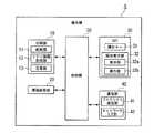
図6は、第2実施形態に係る画像形成システム60の機能ブロック図である。
画像形成システム60は、複合機1(画像形成装置)、パーソナルコンピューター2(ホスト装置)及び複合機1とパーソナルコンピューター2とを接続するLAN(通信回線)3から構成されている。
なお、本図6には、1台のパーソナルコンピューター2を図示したが、実際には、複合機1には、図示しない複数台のパーソナルコンピューターが、LAN3を介して接続されている。FIG. 6 is a functional block diagram of the
The
Although FIG. 6 shows one
パーソナルコンピューター2は、ユーザーインタフェース61、通信部62、記憶部63及び制御部64を備えている。
ユーザーインタフェース61は、液晶ディスプレイや有機ELディスプレイ等から構成される表示部61aを備えている。表示部61aは、制御部64による制御の下に、ユーザーがパーソナルコンピューター2の動作状況を認識するための画像を表示するものである。
また、ユーザーインタフェース61は、マウスやキーボード等から構成される操作部61bを備えている。操作部61bは、ユーザーからパーソナルコンピューター2に対する操作指示を受け付けるものであって、ユーザーによる操作指示に応じた信号を制御部64に出力する。The
The
In addition, the
通信部62は、制御部64による制御の下に、LAN3を介して外部装置と各種情報の送受信を行う。
記憶部63は、各種アプリケーションソフトウェア、複合機1にユーザーの指示を伝達するプリンタドライバ等のパーソナルコンピューター2に接続された各種ハードウェアを制御するドライバ、各種設定値等を記憶している。また、この記憶部63は、複合機1において印刷するべき画像の画像データ(原稿読取部20で読み取った原稿画像データに限らず、通信部62や外部メモリ等から入力される画像データを含む)を記憶している。The
The
制御部64は、内部メモリ、CPU(Central Processing Unit)、及び他の各部(つまり、ユーザーインタフェース61及び記憶部63)とのデータ授受を行う各種入出力インタフェース回線等から構成され、パーソナルコンピューター2の全体動作を制御するものである。
内部メモリは、制御プログラムを記憶している。CPUは、上記制御プログラムや各種制御用データ、ユーザーインタフェース61から入力される信号等に基づいて制御演算を行うことによって、上記他の各部を統括的に制御する。The
The internal memory stores a control program. The CPU performs overall control of the other units by performing control calculations based on the control program, various control data, signals input from the
制御部64は、上記記憶部63の記憶内容を制御する。また、制御部64は、記憶部63に記憶されたアプリケーションソフトウェアやプリンタドライバのプログラム内容及びユーザーの操作指示に従って動作することによって、上記アプリケーションソフトウェアやプリンタドライバの機能を実現する。 The
制御部64は、コピーモード時において、原稿読取部20にて生成された原稿画像データを基に表示部61aの表示画面上に原稿画像をプレビュー表示させると共に各種サイズの印刷用紙を示すアイコンを表示させ、操作部61bから入力される操作信号を基に原稿画像上へのアイコンの移動操作を検知した場合、そのアイコンが示す印刷用紙のサイズに応じた枠線を原稿画像に重ねて表示させて、枠線で囲まれた領域を印刷すべき画像領域(印刷領域)として認識し、印刷領域の画像が、移動操作されたアイコンが示す印刷用紙に印刷されるように印刷指示を出力し、複合機1に印刷させる。 In the copy mode, the
LAN3は、例えば同一社内全域に亘って有線ないし無線にて敷設され、該社内における情報の受け渡しを電子データの送受信にて可能とするものである。そして、複合機1とパーソナルコンピューター2とを通信可能に接続している。 The LAN 3 is laid, for example, in a wired or wireless manner throughout the same company, and enables information exchange within the company by electronic data transmission / reception. The
以下では、上記のように構成された画像形成システム60の動作について説明する。
図7は、コピーモード時における画像形成システム60の動作(正確には制御部64がプリンタドライバを実行する各種処理のシーケンス)を示すフローチャートである。この図7に示すように、コピーモード時において、制御部64は、操作部61b(例えばマウス)から入力される操作信号に基づいてプリンタドラバの所定のダイアログのプレビューボタンが押下されたか否かを判定し(ステップS101)、「Yes」の場合に、記憶部63に予め記憶された印刷すべき画像(ここでは原稿画像、例えば原稿読取部20によって予め読み取ったもの)の画像データを読み出し取得する(ステップS102)。Hereinafter, the operation of the
FIG. 7 is a flowchart showing the operation of the
続いて、制御部64は、記憶部63に記憶されている画像データを基に表示部61aを制御して、表示部61aの表示画面上に原稿画像をプレビュー表示させると共に各種サイズの印刷用紙を示すアイコンを表示させる(ステップS103)。なお、このステップS103の処理では、上記実施形態において説明した図4(a)に示すものと同様の表示を、パーソナルコンピューター2の表示部61aの表示画面(プリンタドライバのダイアログ画面)100上において表示させる。 Subsequently, the
続いて、制御部64は、操作部61bから入力される操作信号(表示部61a上でユーザーにマウスでクリックされた部位の座標を示す信号)を基に原稿画像200上へのアイコン301或いは302の移動操作(ドラッグ操作)を検知したか否かを判定する(ステップS104)。
以下では、一例として、制御部64が、アイコン301のドラッグ操作を検知した場合を想定して説明する。Subsequently, the
In the following, a description will be given assuming that the
制御部64は、上記ステップS104にて「Yes」の場合(例えばアイコン301のドラッグ操作を検知した場合)、ドラッグ操作に応じて表示画面100上でアイコン301が移動するように表示部61aを制御し(図4(b)参照)、原稿画像200上におけるアイコン301の移動位置に、アイコン301が示す印刷用紙のサイズに応じた枠線400を原稿画像200に重ねて表示させ、枠線400で囲まれた領域を印刷すべき画像領域(印刷領域500)として認識する(ステップS105)。 When “Yes” is determined in step S104 (for example, when a drag operation of the
図4(c)は、表示部61aの表示画面100上において、原稿画像200に重ねて表示された枠線400の一例である。表示画面100に表示される原稿画像200は、表示画面100内に収まるよう、原稿読取部20で読み取られた元の原稿画像を一定の倍率で縮小したものであるが、枠線400の縦横サイズ(印刷領域500のサイズ)は、縦置きA4サイズの印刷用紙を原稿画像200と同倍率で縮小したものと同じサイズである。 FIG. 4C is an example of a
続いて、制御部64は、操作部61bから入力される操作信号を基に原稿画像200に重ねて表示された枠線400のドラッグ操作を検知したか否かを判定し(ステップS106)、「No」の場合には後述のステップS108へ移行する一方、「Yes」の場合には、図5(a)に示すように、枠線400のドラッグ操作に応じて枠線400が移動するように表示部61aを制御する(ステップS107)。 Subsequently, the
続いて、制御部64は、操作部61bから入力される操作信号を基に原稿画像200に重ねて表示された枠線400の拡大操作或いは縮小操作を検知したか否かを判定し(ステップS108)、「No」の場合には後述のステップS110へ移行する一方、「Yes」の場合には、図5(b)に示すように、枠線400の拡大操作或いは縮小操作に応じて枠線400が拡大或いは縮小するように表示部61aを制御する(ステップS109)。ここで、拡大操作とは、枠線400の対角線上の2つの角をそれぞれ外側へ向けてドラッグする操作を指し、また、縮小操作とは、枠線400の対角線上の2つの角をそれぞれ内側へ向けてドラッグする操作を指す。なお、図5(b)は、一例として、枠線400の拡大操作が為された場合を示している。 Subsequently, the
続いて、制御部64は、操作部61bから入力される操作信号を基に原稿画像200に重ねて表示された枠線400の回転操作を検知したか否かを判定し(ステップS110)、「No」の場合には後述のステップS112へ移行する一方、「Yes」の場合には、図5(c)に示すように、枠線400の回転操作に応じて枠線400が回転するように表示部61aを制御する(ステップS111)。ここで、回転操作とは、枠線400の少なくとも1つの角を円弧状にドラッグする操作を指す。 Subsequently, the
そして、制御部64は、操作部61bから入力される操作信号を基に表示画面100上に表示された印刷指示アイコン600が押下されたか否か(印刷指示を受けたか否か)を判定し(ステップS112)、「No」の場合には上記ステップS106へ戻る一方、「Yes」の場合には、印刷領域500の画像が、移動操作されたアイコン301が示す印刷用紙(この場合、縦置きA4サイズの印刷用紙)に印刷されるように生成した印刷データに基づく印刷指示を複写機1に出力する(ステップS113)。印刷指示を受けた複写機1は、当該印刷指示に基づいて印刷用紙に画像を印刷して印刷物として出力することとなる。 Then, the
以上のように、本実施形態によれば、ユーザーは、表示部61aのプリンタドライバにおけるダイアログの表示画面100上において、所望の印刷用紙のサイズを示すアイコン301或いは302を、プレビュー表示された原稿画像200上へ移動操作するだけで、容易且つ直感的に印刷領域500を指定することができる。つまり、本実施形態によれば、ユーザーがトリミングという作業を意識せずに、容易な操作で意図する印刷領域500を指定することが可能となる。 As described above, according to the present embodiment, the user can display the preview image of the
以上、本発明の一実施形態について説明したが、本発明はこれに限定されず、本発明の趣旨を逸脱しない範囲において種々変更可能であることは勿論である。
例えば、上記実施形態では、本発明に係る画像形成装置として複合機1を参照しながら説明したが、本発明はこれに限定されず、コピー機などの他の画像形成装置に適用することができる。As mentioned above, although one Embodiment of this invention was described, this invention is not limited to this, Of course, it can change variously in the range which does not deviate from the meaning of this invention.
For example, in the above-described embodiment, the image forming apparatus according to the present invention has been described with reference to the multifunction peripheral 1, but the present invention is not limited to this and can be applied to other image forming apparatuses such as a copying machine. .
例えば、上記実施形態では、本発明に係る画像形成システムのホスト装置としてパーソナルコンピューター2を参照しながら説明したが、本発明はこれに限定されず、タッチパネルを有するタブレット装置、その他の端末装置などの他のホスト装置にも適用することができる。 For example, in the above embodiment, the
1…複合機(画像形成装置)、2…パーソナルコンピューター(ホスト装置)、3…LAN(通信回線)、10…印刷部、20…原稿読取部、30…GUI、32a…表示部、32b…操作部、40…通信部、50…制御部、60…画像形成システム、61a…表示部、61b…操作部、63…記憶部、64…制御部 DESCRIPTION OF
Claims (3)
Translated fromJapanese前記表示部の表示画面上で為された操作に応じた操作信号を出力する操作部と、
原稿を読み取って原稿画像を示す原稿画像データを生成する原稿読取部と、
印刷用紙に画像を印刷して印刷物として出力する印刷部と、
前記原稿画像データを基に前記表示部の表示画面上に前記原稿画像をプレビュー表示させると共に各種サイズの印刷用紙を示すアイコンを表示させ、前記操作信号を基に前記原稿画像上への前記アイコンの移動操作を検知した場合、そのアイコンが示す印刷用紙のサイズに応じた枠線を前記原稿画像に重ねて表示させて前記枠線で囲まれた領域を印刷領域として認識し、印刷指示を受けた場合には前記印刷領域の画像が、移動操作されたアイコンが示す印刷用紙に印刷されるように前記印刷部を制御する制御部と、
を備え、
前記制御部は、
前記操作信号を基に前記表示部の表示画面上において前記原稿画像に重ねて表示された前記枠線の移動操作を検知した場合、その移動操作に応じて前記枠線が移動するように前記表示部を制御し、
前記操作信号を基に前記表示部の表示画面上において前記原稿画像に重ねて表示された前記枠線の拡大操作或いは縮小操作を検知した場合、その拡大操作或いは縮小操作に応じて前記枠線が拡大或いは縮小するように前記表示部を制御し、
前記操作信号を基に前記表示部の表示画面上において前記原稿画像に重ねて表示された前記枠線の回転操作を検知した場合、その回転操作に応じて前記枠線が回転するように前記表示部を制御し、
前記枠線で囲まれた領域に前記原稿画像からはみ出た領域が含まれる場合、前記原稿画像からはみ出た領域を含む前記枠線で囲まれた領域を前記印刷領域として認識することを特徴とする画像形成装置。A display unit for displaying a predetermined image;
An operation unit that outputs an operation signal corresponding to an operation performed on the display screen of the display unit;
A document reading unit that reads a document and generates document image data indicating a document image;
A printing section that prints an image on printing paper and outputs it as a printed matter;
The original image is previewed on the display screen of the display unit based on the original image data, icons indicating various sizes of printing paper are displayed, and the icon on the original image is displayed based on the operation signal. When a movement operation is detected, a frame line corresponding to the size of the printing paper indicated by the icon is displayed over the original image, the area surrounded by the frame line is recognized as a print area, and a print instruction is received In this case, a control unit that controls the printing unit so that the image of the printing area is printed on the printing paper indicated by the moved icon,
Equipped witha,
The controller is
When the moving operation of the frame line displayed on the original image on the display screen of the display unit is detected based on the operation signal, the display is performed so that the frame line moves according to the moving operation. Control the part
When an enlargement operation or reduction operation of the frame line displayed on the original image on the display screen of the display unit is detected based on the operation signal, the frame line is displayed according to the enlargement operation or reduction operation. Controlling the display unit to enlarge or reduce,
When a rotation operation of the frame line displayed on the original image on the display screen of the display unit is detected based on the operation signal, the display is performed so that the frame line is rotated according to the rotation operation. Control the part
When the area surrounded by the frame line includes an area protruding from the document image, the area surrounded by the frame line including the area protruding from the document image is recognized as the print area. Image forming apparatus.
前記画像形成装置に印刷指示を出力するホスト装置と、
前記ホスト装置と前記画像形成装置とを相互接続する通信回線と、を備え、
前記ホスト装置は、
所定の画像を表示する表示部と、
前記表示部の表示画面上で為された操作に応じた操作信号を出力する操作部と、
印刷すべき画像の画像データを記憶する記憶部と、
前記画像データを基に前記表示部の表示画面上に前記画像をプレビュー表示させると共に各種サイズの印刷用紙を示すアイコンを表示させ、前記操作信号を基に前記画像上への前記アイコンの移動操作を検知した場合、そのアイコンが示す印刷用紙のサイズに応じた枠線を前記画像に重ねて表示させて前記枠線で囲まれた領域を印刷領域として認識し、前記印刷領域の画像が、移動操作されたアイコンが示す印刷用紙に印刷されるように前記印刷指示を出力する制御部と、を備え、
前記制御部は、
前記操作信号を基に前記表示部の表示画面上において前記画像に重ねて表示された前記枠線の移動操作を検知した場合、その移動操作に応じて前記枠線が移動するように前記表示部を制御し、
前記操作信号を基に前記表示部の表示画面上において前記画像に重ねて表示された前記枠線の拡大操作或いは縮小操作を検知した場合、その拡大操作或いは縮小操作に応じて前記枠線が拡大或いは縮小するように前記表示部を制御し、
前記操作信号を基に前記表示部の表示画面上において前記画像に重ねて表示された前記枠線の回転操作を検知した場合、その回転操作に応じて前記枠線が回転するように前記表示部を制御し、
前記枠線で囲まれた領域に前記画像からはみ出た領域が含まれる場合、前記画像からはみ出た領域を含む前記枠線で囲まれた領域を前記印刷領域として認識することを特徴とする画像形成システム。
An image forming apparatus that prints an image on a printing paper and outputs it as a printed matter;
A host device that outputs a print instruction to the image forming device;
A communication line interconnecting the host device and the image forming apparatus,
The host device is
A display unit for displaying a predetermined image;
An operation unit that outputs an operation signal corresponding to an operation performed on the display screen of the display unit;
A storage unit for storing image data of an image to be printed;
The image is previewed on the display screen of the display unit based on the image data, icons indicating various sizes of printing paper are displayed, and the icon is moved onto the image based on the operation signal. If detected, a frame line corresponding to the size of the printing paper indicated by the icon is displayed over the image, the area surrounded by the frame line is recognized as a print area, and the image in the print area is moved. A control unit that outputs the print instruction so as to be printed on the printing paper indicated by the icon,
The controller is
When the moving operation of the frame line displayed on theimage on the display screen of the display unit is detected based on the operation signal, the display unit moves the frame line according to the moving operation. Control
When detecting an enlargement operation or down operation of the frame line is displayed superimposed onthe image on the display screen of the display unit based on the operation signal, the frame lines are expanded in accordance with the enlargement operation or down operation Alternatively, the display unit is controlled to reduce,
When the rotation operation of the frame line displayed on theimage on the display screen of the display unit is detected based on the operation signal, the display unit is configured to rotate the frame line according to the rotation operation. Control
In a case where an area protruding from theimage is included in the area surrounded by the frame line, the area surrounded by the frame line including the area protruding from theimage is recognized as the print area. system.
Priority Applications (2)
| Application Number | Priority Date | Filing Date | Title |
|---|---|---|---|
| JP2012176914AJP5810049B2 (en) | 2011-12-08 | 2012-08-09 | Image forming apparatus and image forming system |
| US13/693,193US9325867B2 (en) | 2011-12-08 | 2012-12-04 | Image forming apparatus and image forming system |
Applications Claiming Priority (3)
| Application Number | Priority Date | Filing Date | Title |
|---|---|---|---|
| JP2011269031 | 2011-12-08 | ||
| JP2011269031 | 2011-12-08 | ||
| JP2012176914AJP5810049B2 (en) | 2011-12-08 | 2012-08-09 | Image forming apparatus and image forming system |
Publications (2)
| Publication Number | Publication Date |
|---|---|
| JP2013141196A JP2013141196A (en) | 2013-07-18 |
| JP5810049B2true JP5810049B2 (en) | 2015-11-11 |
Family
ID=48571728
Family Applications (1)
| Application Number | Title | Priority Date | Filing Date |
|---|---|---|---|
| JP2012176914AExpired - Fee RelatedJP5810049B2 (en) | 2011-12-08 | 2012-08-09 | Image forming apparatus and image forming system |
Country Status (2)
| Country | Link |
|---|---|
| US (1) | US9325867B2 (en) |
| JP (1) | JP5810049B2 (en) |
Families Citing this family (5)
| Publication number | Priority date | Publication date | Assignee | Title |
|---|---|---|---|---|
| JP6045459B2 (en)* | 2013-08-30 | 2016-12-14 | 京セラドキュメントソリューションズ株式会社 | Image forming apparatus |
| JP6202051B2 (en)* | 2015-06-29 | 2017-09-27 | コニカミノルタ株式会社 | Image forming apparatus |
| CN110069407B (en)* | 2019-04-03 | 2022-12-16 | 北京云测信息技术有限公司 | Function test method and device for application program |
| JP7349851B2 (en)* | 2019-09-02 | 2023-09-25 | キヤノン株式会社 | Printing control device, method and program |
| JP7669803B2 (en)* | 2021-05-27 | 2025-04-30 | セイコーエプソン株式会社 | Multifunction printer, display control method for multifunction printer, and display control program |
Family Cites Families (15)
| Publication number | Priority date | Publication date | Assignee | Title |
|---|---|---|---|---|
| JP3488129B2 (en)* | 1999-04-21 | 2004-01-19 | シャープ株式会社 | Display device of image forming instruction terminal of image forming apparatus or image forming system |
| US7450114B2 (en)* | 2000-04-14 | 2008-11-11 | Picsel (Research) Limited | User interface systems and methods for manipulating and viewing digital documents |
| AUPQ717700A0 (en) | 2000-04-28 | 2000-05-18 | Canon Kabushiki Kaisha | A method of annotating an image |
| JP2002010056A (en)* | 2000-06-19 | 2002-01-11 | Fuji Photo Film Co Ltd | Image composing device |
| US7454707B2 (en)* | 2002-09-30 | 2008-11-18 | Canon Kabushiki Kaisha | Image editing method, image editing apparatus, program for implementing image editing method, and recording medium recording program |
| JP2006231651A (en)* | 2005-02-24 | 2006-09-07 | Seiko Epson Corp | Printing device |
| US8446631B2 (en)* | 2005-04-13 | 2013-05-21 | Sharp Laboratories Of America, Inc. | Systems and methods for efficiently printing poster documents |
| JP2009141412A (en)* | 2007-12-03 | 2009-06-25 | Noritsu Koki Co Ltd | Print output device |
| JP2010219763A (en) | 2009-03-16 | 2010-09-30 | Kyocera Mita Corp | Image operation display device and image-forming device |
| JP5544736B2 (en)* | 2009-03-26 | 2014-07-09 | 株式会社ニコン | Image processing apparatus and image processing program |
| JP5371560B2 (en)* | 2009-06-09 | 2013-12-18 | キヤノン株式会社 | Layout editing apparatus, layout editing method and program |
| JP5577766B2 (en)* | 2010-03-10 | 2014-08-27 | セイコーエプソン株式会社 | Print control apparatus and print control program |
| US8488183B2 (en)* | 2011-03-10 | 2013-07-16 | Konica Minolta Laboratory U.S.A., Inc. | Moving labels in graphical output to avoid overprinting |
| US8724146B2 (en)* | 2011-03-28 | 2014-05-13 | Apple Inc. | Systems and methods for defining print settings using device movements |
| JP5541240B2 (en)* | 2011-07-12 | 2014-07-09 | コニカミノルタ株式会社 | Image forming apparatus and image processing method |
- 2012
- 2012-08-09JPJP2012176914Apatent/JP5810049B2/ennot_activeExpired - Fee Related
- 2012-12-04USUS13/693,193patent/US9325867B2/ennot_activeExpired - Fee Related
Also Published As
| Publication number | Publication date |
|---|---|
| US20130148148A1 (en) | 2013-06-13 |
| JP2013141196A (en) | 2013-07-18 |
| US9325867B2 (en) | 2016-04-26 |
Similar Documents
| Publication | Publication Date | Title |
|---|---|---|
| JP5599117B2 (en) | Operating device and operating method | |
| JP2009232154A (en) | Image forming apparatus | |
| JP2008276693A (en) | Image forming device and program | |
| JP6143446B2 (en) | Print setting apparatus, control method therefor, and program | |
| CN103369182B (en) | Display input device and possess the image processing system of display input device | |
| JP5810049B2 (en) | Image forming apparatus and image forming system | |
| JP2010088006A (en) | Input/output control device, image reader, and image forming apparatus | |
| US20140009784A1 (en) | Electronic appliance, method for controlling electronic appliance and non-transitory computer readable medium | |
| JP2010023367A (en) | Image forming apparatus and control program therefor | |
| JP2013114338A (en) | Operation device and operation method | |
| JP5269862B2 (en) | Operating device and operating method | |
| JP2011242828A (en) | Operation device, electronic device and image processor provided with operation device, and information display method in operation device | |
| JP2016207175A (en) | Electronic device and display control program | |
| US8848235B2 (en) | Systems and methods for displaying a print preview | |
| JP5934487B2 (en) | Numerical input device and image processing apparatus including the same | |
| JP5977864B2 (en) | Numerical input device and image processing apparatus including the same | |
| JP6054494B2 (en) | Operating device and electronic device | |
| JP6027949B2 (en) | Facsimile machine | |
| JP5380521B2 (en) | Operating device and image forming apparatus | |
| JP5847669B2 (en) | Operating device and electronic device | |
| JP5364665B2 (en) | Image forming apparatus | |
| JP2018045421A (en) | Processing apparatus and image forming apparatus | |
| JP6310105B2 (en) | Numerical input device, image processing apparatus including the same, and control method of these apparatuses | |
| JP5912801B2 (en) | Operating device and operating method | |
| JP6093079B2 (en) | Numerical input device, image processing apparatus including the same, and control method of these apparatuses |
Legal Events
| Date | Code | Title | Description |
|---|---|---|---|
| A621 | Written request for application examination | Free format text:JAPANESE INTERMEDIATE CODE: A621 Effective date:20140722 | |
| A977 | Report on retrieval | Free format text:JAPANESE INTERMEDIATE CODE: A971007 Effective date:20150407 | |
| A131 | Notification of reasons for refusal | Free format text:JAPANESE INTERMEDIATE CODE: A131 Effective date:20150414 | |
| A521 | Request for written amendment filed | Free format text:JAPANESE INTERMEDIATE CODE: A523 Effective date:20150605 | |
| A131 | Notification of reasons for refusal | Free format text:JAPANESE INTERMEDIATE CODE: A131 Effective date:20150707 | |
| A521 | Request for written amendment filed | Free format text:JAPANESE INTERMEDIATE CODE: A523 Effective date:20150717 | |
| TRDD | Decision of grant or rejection written | ||
| A01 | Written decision to grant a patent or to grant a registration (utility model) | Free format text:JAPANESE INTERMEDIATE CODE: A01 Effective date:20150818 | |
| A61 | First payment of annual fees (during grant procedure) | Free format text:JAPANESE INTERMEDIATE CODE: A61 Effective date:20150914 | |
| R150 | Certificate of patent or registration of utility model | Ref document number:5810049 Country of ref document:JP Free format text:JAPANESE INTERMEDIATE CODE: R150 | |
| LAPS | Cancellation because of no payment of annual fees |