JP5807686B2 - Image processing apparatus, image processing method, and program - Google Patents
Image processing apparatus, image processing method, and programDownload PDFInfo
- Publication number
- JP5807686B2 JP5807686B2JP2013557372AJP2013557372AJP5807686B2JP 5807686 B2JP5807686 B2JP 5807686B2JP 2013557372 AJP2013557372 AJP 2013557372AJP 2013557372 AJP2013557372 AJP 2013557372AJP 5807686 B2JP5807686 B2JP 5807686B2
- Authority
- JP
- Japan
- Prior art keywords
- matrix
- image processing
- environment
- virtual object
- processing apparatus
- Prior art date
- Legal status (The legal status is an assumption and is not a legal conclusion. Google has not performed a legal analysis and makes no representation as to the accuracy of the status listed.)
- Expired - Fee Related
Links
Images


Classifications
- G—PHYSICS
- G06—COMPUTING OR CALCULATING; COUNTING
- G06F—ELECTRIC DIGITAL DATA PROCESSING
- G06F3/00—Input arrangements for transferring data to be processed into a form capable of being handled by the computer; Output arrangements for transferring data from processing unit to output unit, e.g. interface arrangements
- G06F3/01—Input arrangements or combined input and output arrangements for interaction between user and computer
- G06F3/03—Arrangements for converting the position or the displacement of a member into a coded form
- G—PHYSICS
- G06—COMPUTING OR CALCULATING; COUNTING
- G06F—ELECTRIC DIGITAL DATA PROCESSING
- G06F1/00—Details not covered by groups G06F3/00 - G06F13/00 and G06F21/00
- G06F1/16—Constructional details or arrangements
- G06F1/1613—Constructional details or arrangements for portable computers
- G06F1/1633—Constructional details or arrangements of portable computers not specific to the type of enclosures covered by groups G06F1/1615 - G06F1/1626
- G06F1/1684—Constructional details or arrangements related to integrated I/O peripherals not covered by groups G06F1/1635 - G06F1/1675
- G06F1/1694—Constructional details or arrangements related to integrated I/O peripherals not covered by groups G06F1/1635 - G06F1/1675 the I/O peripheral being a single or a set of motion sensors for pointer control or gesture input obtained by sensing movements of the portable computer
- G—PHYSICS
- G06—COMPUTING OR CALCULATING; COUNTING
- G06F—ELECTRIC DIGITAL DATA PROCESSING
- G06F3/00—Input arrangements for transferring data to be processed into a form capable of being handled by the computer; Output arrangements for transferring data from processing unit to output unit, e.g. interface arrangements
- G06F3/01—Input arrangements or combined input and output arrangements for interaction between user and computer
- G06F3/011—Arrangements for interaction with the human body, e.g. for user immersion in virtual reality
- G—PHYSICS
- G06—COMPUTING OR CALCULATING; COUNTING
- G06F—ELECTRIC DIGITAL DATA PROCESSING
- G06F3/00—Input arrangements for transferring data to be processed into a form capable of being handled by the computer; Output arrangements for transferring data from processing unit to output unit, e.g. interface arrangements
- G06F3/01—Input arrangements or combined input and output arrangements for interaction between user and computer
- G06F3/03—Arrangements for converting the position or the displacement of a member into a coded form
- G06F3/033—Pointing devices displaced or positioned by the user, e.g. mice, trackballs, pens or joysticks; Accessories therefor
- G06F3/0346—Pointing devices displaced or positioned by the user, e.g. mice, trackballs, pens or joysticks; Accessories therefor with detection of the device orientation or free movement in a 3D space, e.g. 3D mice, 6-DOF [six degrees of freedom] pointers using gyroscopes, accelerometers or tilt-sensors
- G—PHYSICS
- G06—COMPUTING OR CALCULATING; COUNTING
- G06F—ELECTRIC DIGITAL DATA PROCESSING
- G06F3/00—Input arrangements for transferring data to be processed into a form capable of being handled by the computer; Output arrangements for transferring data from processing unit to output unit, e.g. interface arrangements
- G06F3/01—Input arrangements or combined input and output arrangements for interaction between user and computer
- G06F3/048—Interaction techniques based on graphical user interfaces [GUI]
- G06F3/0481—Interaction techniques based on graphical user interfaces [GUI] based on specific properties of the displayed interaction object or a metaphor-based environment, e.g. interaction with desktop elements like windows or icons, or assisted by a cursor's changing behaviour or appearance
- G06F3/04815—Interaction with a metaphor-based environment or interaction object displayed as three-dimensional, e.g. changing the user viewpoint with respect to the environment or object
- G—PHYSICS
- G06—COMPUTING OR CALCULATING; COUNTING
- G06F—ELECTRIC DIGITAL DATA PROCESSING
- G06F3/00—Input arrangements for transferring data to be processed into a form capable of being handled by the computer; Output arrangements for transferring data from processing unit to output unit, e.g. interface arrangements
- G06F3/01—Input arrangements or combined input and output arrangements for interaction between user and computer
- G06F3/048—Interaction techniques based on graphical user interfaces [GUI]
- G06F3/0484—Interaction techniques based on graphical user interfaces [GUI] for the control of specific functions or operations, e.g. selecting or manipulating an object, an image or a displayed text element, setting a parameter value or selecting a range
- G06F3/04842—Selection of displayed objects or displayed text elements
- G—PHYSICS
- G06—COMPUTING OR CALCULATING; COUNTING
- G06T—IMAGE DATA PROCESSING OR GENERATION, IN GENERAL
- G06T19/00—Manipulating 3D models or images for computer graphics
- G06T19/20—Editing of 3D images, e.g. changing shapes or colours, aligning objects or positioning parts
- G—PHYSICS
- G06—COMPUTING OR CALCULATING; COUNTING
- G06T—IMAGE DATA PROCESSING OR GENERATION, IN GENERAL
- G06T2219/00—Indexing scheme for manipulating 3D models or images for computer graphics
- G06T2219/20—Indexing scheme for editing of 3D models
- G06T2219/2004—Aligning objects, relative positioning of parts
Landscapes
- Engineering & Computer Science (AREA)
- Theoretical Computer Science (AREA)
- General Engineering & Computer Science (AREA)
- Physics & Mathematics (AREA)
- General Physics & Mathematics (AREA)
- Human Computer Interaction (AREA)
- Computer Hardware Design (AREA)
- Architecture (AREA)
- Computer Graphics (AREA)
- Software Systems (AREA)
- User Interface Of Digital Computer (AREA)
- Processing Or Creating Images (AREA)
Description
Translated fromJapanese本開示は、画像処理装置、画像処理方法及びプログラムに関する。 The present disclosure relates to an image processing device, an image processing method, and a program.
近年、実世界に付加的な情報を重畳してユーザに呈示する拡張現実(AR:Augmented Reality)と呼ばれる技術が注目されている。AR技術においてユーザに呈示される情報は、アノテーションとも呼ばれ、テキスト、アイコン又はアニメーションなどの様々な形態の仮想的なオブジェクトを用いて可視化され得る。 In recent years, a technique called augmented reality (AR) that superimposes additional information on the real world and presents it to the user has attracted attention. Information presented to the user in AR technology is also called annotation, and can be visualized using various forms of virtual objects such as text, icons or animations.
下記非特許文献1は、仮想オブジェクトを配置する前の段階で実空間をモデリングするための技術の一例を示している。下記非特許文献2は、仮想オブジェクトを撮像画像に重畳する際に必要とされる撮像装置の位置及び姿勢を算出することを目的とした、自然マーカを利用した技術の一例を示している。 Non-Patent
AR技術は、ユーザとのインタラクションを伴うアプリケーションにおいても活用され得る。例えば、下記特許文献1は、ユーザにより操作され得るアイコンを仮想オブジェクトとして表示する技術を開示している。 AR technology can also be utilized in applications involving user interaction. For example,
しかしながら、上記特許文献1に記載された技術では、仮想オブジェクトは、2次元の画面上でユーザによる操作に応じて動くのみである。そのため、AR技術の利点の1つである現実感が十分に実現されているとはいい難い。ユーザとのインタラクションにおいて現実感を得るためには、3次元空間内で仮想オブジェクトを自在に操作することのできる仕組みが提供されることが望ましい。 However, in the technique described in
本開示によれば、画像を撮像した端末の位置及び姿勢を基準として前記画像に映る環境の位置及び姿勢を表現する環境認識行列を認識する認識部と、前記環境認識行列の逆行列を計算する計算部と、第1の時点で認識される前記環境認識行列の前記逆行列に基づく第1の位置又は第1の姿勢と、後続する第2の時点で認識される前記環境認識行列の前記逆行列に基づく第2の位置又は第2の姿勢との間の差分に応じた3次元的な操作量で、前記環境内に配置される仮想オブジェクトの操作を制御する操作制御部と、を備える画像処理装置が提供される。 According to the present disclosure, a recognition unit for recognizing an environment recognition matrix expressing the position and orientation of an environment reflected in the image on the basis of the position and orientation of the terminal that captured the image, and an inverse matrix of the environment recognition matrix are calculated. A calculation unit, a first position or a first attitude based on the inverse matrix of the environment recognition matrix recognized at a first time point, and the inverse of the environment recognition matrix recognized at a subsequent second time point; An operation control unit that controls an operation of a virtual object arranged in the environment with a three-dimensional operation amount corresponding to a difference between the second position or the second posture based on the matrix. A processing device is provided.
また、本開示によれば、画像を撮像した端末の位置及び姿勢を基準として前記画像に映る環境の位置及び姿勢を表現する環境認識行列を認識することと、前記環境認識行列の逆行列を計算することと、第1の時点で認識される前記環境認識行列の前記逆行列に基づく第1の位置又は第1の姿勢と、後続する第2の時点で認識される前記環境認識行列の前記逆行列に基づく第2の位置又は第2の姿勢との間の差分に応じた3次元的な操作量で、前記環境内に配置される仮想オブジェクトの操作を制御することと、を含む画像処理方法が提供される。 In addition, according to the present disclosure, an environment recognition matrix expressing the position and orientation of the environment shown in the image is recognized based on the position and orientation of the terminal that captured the image, and the inverse matrix of the environment recognition matrix is calculated. A first position or a first attitude based on the inverse matrix of the environment recognition matrix recognized at a first time point, and the inverse of the environment recognition matrix recognized at a subsequent second time point. Controlling an operation of a virtual object arranged in the environment with a three-dimensional operation amount corresponding to a difference between the second position or the second posture based on the matrix. Is provided.
また、本開示によれば、コンピュータを、画像を撮像した端末の位置及び姿勢を基準として前記画像に映る環境の位置及び姿勢を表現する環境認識行列を認識する認識部と、前記環境認識行列の逆行列を計算する計算部と、第1の時点で認識される前記環境認識行列の前記逆行列に基づく第1の位置又は第1の姿勢と、後続する第2の時点で認識される前記環境認識行列の前記逆行列に基づく第2の位置又は第2の姿勢との間の差分に応じた3次元的な操作量で、前記環境内に配置される仮想オブジェクトの操作を制御する操作制御部と、として機能させるためのプログラムが提供される。 Further, according to the present disclosure, the computer recognizes an environment recognition matrix that represents the position and orientation of the environment shown in the image with reference to the position and orientation of the terminal that captured the image, and the environment recognition matrix A calculation unit for calculating an inverse matrix, a first position or a first posture based on the inverse matrix of the environment recognition matrix recognized at a first time point, and the environment recognized at a subsequent second time point An operation control unit that controls the operation of the virtual object arranged in the environment with a three-dimensional operation amount corresponding to the difference between the second position or the second posture based on the inverse matrix of the recognition matrix. And a program for functioning as is provided.
本開示に係る技術によれば、3次元空間内で仮想オブジェクトを自在に操作することのできる仕組みが提供される。 According to the technique according to the present disclosure, a mechanism capable of freely operating a virtual object in a three-dimensional space is provided.
以下に添付図面を参照しながら、本開示の好適な実施の形態について詳細に説明する。なお、本明細書及び図面において、実質的に同一の機能構成を有する構成要素については、同一の符号を付することにより重複説明を省略する。 Hereinafter, preferred embodiments of the present disclosure will be described in detail with reference to the accompanying drawings. In addition, in this specification and drawing, about the component which has the substantially same function structure, duplication description is abbreviate | omitted by attaching | subjecting the same code | symbol.
また、以下の順序で説明を行う。
1.基本的な原理
1−1.概要
1−2.基本的なパラメータ
1−3.3次元的な操作量の例
2.画像処理装置の構成例
2−1.ハードウェア構成
2−2.機能構成
2−3.操作シナリオ
2−4.処理の流れ
2−5.表示のバリエーション
2−6.仮想オブジェクトの共有
3.まとめThe description will be given in the following order.
1. Basic principle 1-1. Outline 1-2. Basic parameters 1-3. Examples of three-dimensional manipulated variables Configuration example of image processing apparatus 2-1. Hardware configuration 2-2. Functional configuration 2-3. Operation scenario 2-4. Flow of processing 2-5. Display variations 2-6. 2. Sharing virtual objects Summary
<1.基本的な原理>
まず、図1〜図8を用いて、本開示に係る技術の基本的な原理について説明する。<1. Basic Principle>
First, the basic principle of the technology according to the present disclosure will be described with reference to FIGS.
[1−1.概要]
図1は、本開示に係る技術が適用され得る環境の一例を示す説明図である。図1を参照すると、環境1、及び環境1を映す画像を撮像する画像処理装置100が示されている。図1の例において、環境1には、物体11が存在している。画像処理装置100は、典型的には、撮像部(図示せず)及び表示部110を備える。画像処理装置100の撮像部は、環境1を映す映像を構成する一連の画像を撮像する。そして、画像処理装置100は、撮像画像を入力画像として画像処理を行い、3次元空間に仮想オブジェクトを配置する。仮想オブジェクトは、後に説明するように、画像処理装置100を動かすことによりユーザにより操作される。画像処理装置100の表示部110は、仮想オブジェクトが重畳された出力画像を表示する。[1-1. Overview]
FIG. 1 is an explanatory diagram illustrating an example of an environment to which the technology according to the present disclosure can be applied. Referring to FIG. 1, an
画像処理装置100は、仮想オブジェクトを何らかの基準環境内に配置する。即ち、仮想オブジェクトの位置及び姿勢は、基準環境と関連付けられる座標系(以下、基準座標系という)において定義される。以下の説明では、物体11を含む環境1が、基準環境であるものとする。実際には、基準環境は、屋内であるか屋外であるかを問わず、任意の環境であってよい。他の実施形態として、物体固有の座標系を有する1つの物体が基準環境として扱われてもよい。その場合、物体固有の座標系が基準座標系となる。 The
図1では、画像処理装置100の一例としてタブレットPCを示している。しかしながら、画像処理装置100は、かかる例に限定されない。画像処理装置100は、例えば、ノートブックPC、ポケットPC、スマートフォン、ゲーム端末、PND(Portable Navigation Device)、コンテンツプレーヤ又はデジタル家電機器などであってもよい。 In FIG. 1, a tablet PC is shown as an example of the
[1−2.基本的なパラメータ]
本開示に係る技術において、基準環境内に配置される仮想オブジェクトの位置及び姿勢は、いくつかのパラメータを用いた計算を通じて決定される。最も基本的なパラメータは、環境認識行列である。[1-2. Basic parameters]
In the technology according to the present disclosure, the position and orientation of the virtual object arranged in the reference environment are determined through calculation using several parameters. The most basic parameter is the environment recognition matrix.
(1)環境認識行列
環境認識行列は、入力画像を撮像した端末の基準環境内の位置及び姿勢を基準として、基準環境の位置及び姿勢を表現する行列である。環境認識行列は、典型的には、3次元空間内の並行移動、回転及びスケーリング(拡大/縮小)を表す座標変換行列(例えば、4行4列の同次変換行列)であってよい。(1) Environment recognition matrix The environment recognition matrix is a matrix that represents the position and orientation of the reference environment on the basis of the position and orientation in the reference environment of the terminal that captured the input image. The environment recognition matrix may typically be a coordinate transformation matrix (for example, a 4 × 4 homogeneous transformation matrix) representing translation, rotation, and scaling (enlargement / reduction) in a three-dimensional space.
図2を参照すると、基準環境1と関連付けられる基準座標系CS1、及び画像処理装置100の装置固有の座標系CS0が示されている。装置固有の座標系CS0は、例えば、表示部110の画面の2次元座標軸と奥行き軸とにより構成され得る。画像処理装置100の装置固有の座標系CS0を基準とする基準座標系CS1の相対的な位置及び姿勢は、公知の画像認識技術を活用することにより、入力画像を用いて認識され得る。ここで活用される画像認識技術とは、例えば、SfM(Structure from Motion)法、SLAM(Simultaneous Localization And Mapping)法、又は上記非特許文献1若しくは2に記載されている手法などであってよい。その代わりに、赤外線センサを用いたより簡易な環境認識技術が活用されてもよい。Referring to FIG. 2, a reference coordinate system CS1 associated with the
ここで、画像処理装置100の装置固有の座標系CS0の位置及び姿勢が、単位行列M0により表現されるものと仮定する。すると、基準環境1内の任意の位置及び姿勢を行列M0からの座標変換(並行移動、回転及びスケーリング)として認識することが可能となる。従って、位置及び姿勢のセットが1つの座標変換行列によって表現される。上述した環境認識行列は、そうした座標変換行列の1つである。環境認識行列Mrecogは、画像処理装置100の位置及び姿勢(即ち単位行列M0)を基準として、基準座標系CS1の位置及び姿勢を表現する。Here, it is assumed that the position and orientation of the coordinate system CS0 unique to the apparatus of the
(2)操作配置行列
上述した前提の下で、環境認識行列Mrecogの逆行列Mrecog−1は、基準座標系CS1の位置及び姿勢を基準とした画像処理装置100の位置及び姿勢を表現する行列となる。図3は、環境認識行列の逆行列Mrecog−1が表現する座標変換を概念的に示している。(2) Operation Arrangement Matrix Under the premise described above, the inverse matrix Mrecog−1 of the environment recognition matrix Mrecog represents the position and orientation of the
操作配置行列Mmobileは、仮想オブジェクトを操作するためにユーザにより移動される画像処理装置100の位置及び姿勢を表現する行列である。なお、本明細書において、特に「並行」移動と明示されない場合には、「移動」との用語は並行移動及び回転の双方を含み得るものとする。操作配置行列Mmobileは、例えば、次式のように、環境認識行列の逆行列Mrecog−1と等しくてもよい。The operation arrangement matrix Mmobile is a matrix expressing the position and orientation of the

図4は、式(1)が採用される場合の操作配置行列Mmobileが表現する座標変換を概念的に示している。但し、操作位置の調整を容易とするために、次に説明するようなオフセット行列が用いられてもよい。FIG. 4 conceptually shows coordinate transformation expressed by the operation arrangement matrix Mmobile when Expression (1) is adopted. However, in order to facilitate adjustment of the operation position, an offset matrix as described below may be used.
(3)オフセット行列
図5は、オフセット行列Ttouchを算入して決定される操作配置行列Mmobileを概念的に示している。オフセット行列Ttouchは、画像処理装置100の画面上でのユーザ入力位置に応じて決定される、当該画面に沿った方向への並行移動を表現する座標変換行列である。オフセット行列Ttouchが算入される場合、操作配置行列Mmobileは、次式のように計算され得る。(3) Offset Matrix FIG. 5 conceptually shows an operation arrangement matrix Mmobile that is determined by including the offset matrix Ttouch . The offset matrix Ttouch is a coordinate transformation matrix that represents parallel movement in a direction along the screen, which is determined according to the user input position on the screen of the
このようにオフセット行列Ttouchが算入される場合、ユーザにとって、画像処理装置100を動かす代わりに画面上の所望の位置で操作(例えば、タッチ又はクリックなど)を行うことで、操作位置を細かく調整することが容易となる。When the offset matrix Ttouch is included in this way, the user can finely adjust the operation position by performing an operation (for example, touch or click) at a desired position on the screen instead of moving the
[1−3.3次元的な操作量の例]
ここで、ユーザが、時刻t1から時刻t2にかけて画像処理装置100を移動させたものとする。その場合、上述した原理に従って、時刻t1における操作配置行列Mmobile(t1)と時刻t2における操作配置行列Mmobile(t2)とを計算することができる。操作配置行列Mmobile(t1)が表現する位置と操作配置行列Mmobile(t2)が表現する位置との差分は、時刻t1から時刻t2にかけての画像処理装置100の並行移動(及び画面上でのユーザ入力位置の変化)に対応する並行移動量を示す。操作配置行列Mmobile(t1)が表現する姿勢と操作配置行列Mmobile(t2)が表現する姿勢との差分は、時刻t1から時刻t2にかけての画像処理装置100の回転に対応する回転量を示す。本開示に係る技術では、これら並行移動量及び回転量に従って、基準環境内に配置される仮想オブジェクトが3次元的に操作される。[1-3. Example of three-dimensional manipulated variable]
Here, it is assumed that the user moves the
図6の例では、まず、時刻t1において、操作配置行列Mmobile(t1)が決定されている。また、後続する時刻t2において、操作配置行列Mmobile(t2)が決定されている。これら操作配置行列から、次式のように並行移動操作量Dmovが計算される。In the example of FIG. 6, first, at time t1, the operation arrangement matrix Mmobile (t1) is determined. Further, at the subsequent time t2, the operation arrangement matrix Mmobile (t2) is determined. From these operation arrangement matrices, the parallel movement operation amount Dmov is calculated as in the following equation.
式(3)において、Vmobile(t)は、操作配置行列Mmobile(t)の並行移動成分を表すものとする。図7の例では、2つの操作配置行列Mmobile(t1)及びMmobile(t2)から、次式のように回転操作量Drotが計算される。In Expression (3), Vmobile (t) represents a parallel movement component of the operation arrangement matrix Mmobile (t). In the example of FIG. 7, the rotation operation amount Drot is calculated from the two operation arrangement matrices Mmobile (t1) and Mmobile (t2) as in the following equation.
式(4)において、Rmobile(t)は、操作配置行列Mmobile(t)の回転成分を表すものとする。なお、式(3)及び式(4)は一例に過ぎない。例えば、式(3)又は式(4)の右辺に、操作量を増幅し又は縮小するための係数が乗算されてもよい。In Expression (4), Rmobile (t) represents a rotation component of the operation arrangement matrix Mmobile (t). In addition, Formula (3) and Formula (4) are only examples. For example, the right side of Expression (3) or Expression (4) may be multiplied by a coefficient for amplifying or reducing the operation amount.
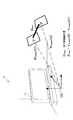
図8は、本開示に係る技術に従って実行される仮想オブジェクトの操作の一例について説明するための説明図である。ここでは、一例として、物体11から仮想オブジェクトを引き出すようなARアプリケーションが想定される。図8に示した操作前行列Mpreは、画像処理装置100により認識される物体11の位置及び姿勢を表現する行列に等しい。仮想オブジェクト21は、物体11と関連付けられる仮想オブジェクトである。例えば、画像処理装置100が物体11の位置及び姿勢を認識した後、時刻t1から時刻t2にかけてユーザが画像処理装置100を図示された通りに移動させたものとする。すると、画像処理装置100は、操作配置行列Mmobile(t1)と操作配置行列Mmobile(t2)との間の差分に応じた3次元的な操作量を決定する。図8の例では、並行移動操作量Dmovが決定されている。そして、画像処理装置100は、並行移動操作量Dmovに従って、仮想オブジェクト21を移動させる。図8の例のように、操作の起点となる位置及び姿勢が操作前行列Mpreにより表現される場合、操作後の仮想オブジェクト21の位置及び姿勢を表現する操作後行列Mpostは、次のように計算される。FIG. 8 is an explanatory diagram for describing an example of a virtual object operation performed according to the technique according to the present disclosure. Here, as an example, an AR application that draws a virtual object from the
なお、並行移動の代わりに回転が行われる場合には、操作後行列Mpostは、式(6)のように計算される。並行移動及び回転の双方が行われる場合には、操作後行列Mpostは、式(7)のように計算される。When rotation is performed instead of parallel movement, thepost- operation matrix Mpost is calculated as shown in Equation (6). When both translation and rotation are performed, thepost- operation matrix Mpost is calculated as shown in Equation (7).
図8の例において、時刻t2における画像処理装置100からの仮想オブジェクト21の見え方は、操作後行列Mpostと時刻t2における環境認識行列Mrecog(t2)との積に相当する次のような座標変換として表現され得る。In the example of FIG. 8, the appearance of the
本節で説明した原理に従って、ユーザは、画像処理装置100のような端末を動かしながらこれを操作することにより、3次元的な操作量を自在に指定することができる。以下、上述した原理に基づく画像処理装置100の構成の一例について詳細に説明する。 In accordance with the principle described in this section, the user can freely specify a three-dimensional operation amount by operating a terminal such as the
<2.画像処理装置の構成例>
[2−1.ハードウェア構成]
図9は、一実施形態に係る画像処理装置100のハードウェア構成の一例を示すブロック図である。図9を参照すると、画像処理装置100は、撮像部102、センサ部104、入力部106、記憶部108、表示部110、通信部112、バス116及び制御部118を備える。<2. Configuration example of image processing apparatus>
[2-1. Hardware configuration]
FIG. 9 is a block diagram illustrating an example of a hardware configuration of the
(1)撮像部
撮像部102は、画像を撮像するカメラモジュールである。撮像部102は、CCD(Charge Coupled Device)又はCMOS(Complementary Metal Oxide Semiconductor)などの撮像素子を用いて実空間を撮像し、撮像画像を生成する。撮像部102により生成される一連の撮像画像は、映像を構成する。なお、撮像部102は、必ずしも画像処理装置100の一部でなくてもよい。例えば、画像処理装置100と有線又は無線で接続される撮像装置が撮像部102として扱われてもよい。また、撮像部102は、撮像部102と被写体との間の距離を画素ごとに測定する深度(depth)センサを含んでいてもよい。深度センサから出力される深度データは、環境の認識のために利用され得る。(1) Imaging unit The
(2)センサ部
センサ部104は、測位センサ、加速度センサ及びジャイロセンサなどの様々なセンサを含み得る。センサ部104において得られる測定結果は、環境の認識の支援、地理的な位置に特化したデータの取得、又はユーザ入力の検出などの様々な用途のために利用されてよい。なお、センサ部104は、画像処理装置100の構成から省略されてもよい。(2) Sensor Unit The
(3)入力部
入力部106は、ユーザが画像処理装置100を操作し又は画像処理装置100へ情報を入力するために使用される入力デバイスである。入力部106は、例えば、表示部110の画面上へのユーザによるタッチを検出するタッチセンサを含んでもよい。その代わりに(又はそれに加えて)、入力部106は、マウス若しくはタッチパッドなどのポインティングデバイスを含んでもよい。さらに、入力部106は、キーボード、キーパッド、ボタン又はスイッチなどのその他の種類の入力デバイスを含んでもよい。(3) Input unit The
(4)記憶部
記憶部108は、半導体メモリ又はハードディスクなどの記憶媒体により構成され、画像処理装置100による処理のためのプログラム及びデータを記憶する。記憶部108により記憶されるデータは、例えば、撮像画像データ、センサデータ及び後に説明するデータベース(DB)内のデータを含み得る。なお、本明細書で説明するプログラム及びデータの一部は、記憶部108により記憶されることなく、外部のデータソース(例えば、データサーバ、ネットワークストレージ又は外付けメモリなど)から取得されてもよい。(4) Storage Unit The
(5)表示部
表示部110は、LCD(Liquid Crystal Display)、OLED(Organic light-Emitting Diode)又はCRT(Cathode Ray Tube)などのディスプレイを含む表示モジュールである。表示部110は、例えば、画像処理装置100により生成される出力画像を表示するために使用される。なお、表示部110もまた、必ずしも画像処理装置100の一部でなくてもよい。例えば、画像処理装置100と有線又は無線で接続される表示装置が表示部110として扱われてもよい。(5) Display Unit The
(6)通信部
通信部112は、画像処理装置100による他の装置との間の通信を仲介する通信インタフェースである。通信部112は、任意の無線通信プロトコル又は有線通信プロトコルをサポートし、他の装置との間の通信接続を確立する。(6) Communication Unit The
(7)バス
バス116は、撮像部102、センサ部104、入力部106、記憶部108、表示部110、通信部112及び制御部118を相互に接続する。(7) Bus The
(8)制御部
制御部118は、CPU(Central Processing Unit)又はDSP(Digital Signal Processor)などのプロセッサに相当する。制御部118は、記憶部108又は他の記憶媒体に記憶されるプログラムを実行することにより、後に説明する画像処理装置100の様々な機能を動作させる。(8) Control Unit The
[2−2.機能構成]
図10は、図9に示した画像処理装置100の記憶部108及び制御部118により実現される論理的機能の構成の一例を示すブロック図である。図10を参照すると、画像処理装置100は、画像取得部120、認識部130、計算部140、物体DB150、コンテンツDB160、操作制御部170及び表示制御部180を備える。[2-2. Functional configuration]
FIG. 10 is a block diagram illustrating an example of a configuration of logical functions realized by the
(1)画像取得部
画像取得部120は、撮像部102により生成される撮像画像を入力画像として取得する。画像取得部120により取得される入力画像は、実空間を映す映像を構成する個々のフレームであってよい。画像取得部120は、取得した入力画像を、認識部130及び表示制御部180へ出力する。(1) Image Acquisition Unit The
(2)認識部
認識部130は、画像取得部120から入力される入力画像を用いて、基準環境の位置及び姿勢を表現する上述した環境認識行列を認識する。認識部130は、環境認識行列を認識するために、SfM法又はSLAM法などの公知の画像認識技術を活用し得る。その代わりに又はそれに加えて、認識部130は、撮像部102に設けられ得る深度センサからの深度データに基づいて、環境認識行列を認識してもよい。また、認識部130は、赤外線測距システム又はモーションキャプチャシステムなどの環境認識システムからの出力データに基づいて、環境認識行列を認識してもよい。(2) Recognizing Unit The recognizing
例えば、SLAM法が活用される場合には、認識部130は、端末の位置、姿勢、速度及び角速度、並びに入力画像に映る1つ以上の特徴点の位置を含む状態変数を、拡張カルマンフィルタの原理に基づいてフレームごとに更新する。それにより、端末の位置及び姿勢を基準とする基準環境の位置及び姿勢を、単眼カメラからの入力画像を用いて認識することができる。認識部130は、認識した基準環境の位置及び姿勢を、端末の位置及び姿勢からの座標変換に相当する環境認識行列Mrecogによって表現する。なお、SLAM法の詳しい説明は、“Real-Time Simultaneous Localization and Mapping with a Single Camera”(Andrew J.Davison,Proceedings of the 9th IEEE International Conference on Computer Vision Volume 2, 2003, pp.1403-1410)に記載されている。For example, when the SLAM method is used, the recognizing
認識部130は、このように認識される環境認識行列Mrecogを、計算部140及び操作制御部170へ出力する。The
また、認識部130は、図8の例のように仮想オブジェクトの位置及び姿勢が基準環境内の物体の位置及び姿勢に関連付けられる場合には、入力画像に映る物体の位置及び姿勢をも認識する。例えば、物体DB150は、1つ以上の物体の各々の既知の特徴量データと当該物体の識別子とを予め記憶する。そして、認識部130は、入力画像から抽出される特徴量データを物体DB150により記憶されている特徴量データと照合することにより、入力画像に映る物体を識別し得る。認識部130は、このように識別される物体の基準座標系での位置及び姿勢を表現する座標変換行列を、環境認識行列Mrecogと同様に認識する。Further, when the position and orientation of the virtual object are associated with the position and orientation of the object in the reference environment as in the example of FIG. 8, the
(3)計算部
計算部140は、認識部130から入力される環境認識行列の逆行列Mrecog−1を計算する。例えば、環境認識行列Mrecogは、4行4列の同次変換行列である。従って、環境認識行列の逆行列Mrecog−1もまた4行4列の同次変換行列であり、Mrecog・Mrecog−1=M0(単位行列)を満たす。環境認識行列の逆行列Mrecog−1は、基準座標系の位置及び姿勢から端末の位置及び姿勢への座標変換を表現する。計算部140は、計算した環境認識行列の逆行列Mrecog−1を操作制御部170へ出力する。(3) Calculation Unit The
(4)物体DB
物体DB150は、上述したように、ARアプリケーションの目的に応じて認識されるべき物体の既知の特徴量データと識別子とを予め記憶する。(4) Object DB
As described above, the
(5)コンテンツDB
コンテンツDB160は、ユーザにより操作可能な仮想オブジェクトの識別子、属性データ及び関連付けられる物体の識別子を予め記憶する。仮想オブジェクトの属性データは、仮想オブジェクトの表示属性(例えば、位置及び姿勢の初期値、形状並びに色など)と、仮想オブジェクトの操作属性(例えば、並行移動及び回転がそれぞれ可能か、など)とを含み得る。(5) Content DB
The
(6)操作制御部170
操作制御部170は、上述した様々なパラメータを用いて、入力画像に映る環境内に配置される仮想オブジェクトの操作を制御する。(6)
The
例えば、操作制御部170は、操作の開始に対応する第1の時点において、環境認識行列の逆行列Mrecog−1に基づいて、3次元の基準環境内の操作位置及び姿勢を表現する操作配置行列Mmobileを決定する。操作制御部170は、例えば、上記式(1)に従って、環境認識行列の逆行列Mrecog−1に等しい操作配置行列Mmobileを決定してよい。また、操作制御部170は、上記式(2)に従い、端末の画面上でのユーザ入力位置に応じたオフセット行列を算入して操作配置行列Mmobileを決定してもよい。For example, at the first time corresponding to the start of the operation, the
また、操作制御部170は、操作対象の仮想オブジェクトを特定する。操作対象の仮想オブジェクトは、入力画像に映る物体の中から何らかの基準で選択される物体に関連付けられるオブジェクトであってもよい。また、操作対象の仮想オブジェクトは、画面上でユーザにより(例えばタッチ又はクリックなどで)指定されるオブジェクトであってもよい。 Further, the
さらに、操作制御部170は、操作の終了(操作の途中であってもよい)に対応する第2の時点において、環境認識行列の逆行列Mrecog−1に基づいて、上記式(1)又は式(2)に従い、3次元の基準環境内の操作位置及び姿勢を表現する操作配置行列Mmobileを再び決定する。Furthermore, the
そして、操作制御部170は、操作開始時及び操作終了時の2つの操作配置行列Mmobileの差分に応じて、仮想オブジェクトの操作量を決定する。例えば、コンテンツDB160により記憶されているデータが、操作対象の仮想オブジェクトが並行移動可能であることを示しているものとする。すると、操作制御部170は、2つの操作配置行列Mmobileの並行移動成分の間の差分に応じて、並行移動操作量Dmovを計算する。また、コンテンツDB160により記憶されているデータが、操作対象の仮想オブジェクトが回転可能であることを示しているものとする。すると、操作制御部170は、2つの操作配置行列Mmobileの回転成分の間の差分に応じて、回転操作量Drotを計算する。Then, the
操作制御部170は、これら操作量を計算すると、算出された操作量に従って、操作対象の仮想オブジェクトの配置を変更する。操作前後の仮想オブジェクトの配置の間の関係は、上記式(6)〜式(8)のいずれかであってよい。 When the
操作制御部170は、このようにユーザによる操作に応じて更新される仮想オブジェクトの配置を表現する座標変換行列(操作後行列Mpost)を、表示制御部180へ出力する。The
操作の開始に対応する上述した第1の時点は、端末において第1のユーザ入力が検出された時点であってもよく、操作の終了に対応する上述した第2の時点は、端末において第2のユーザ入力が検出された時点であってもよい。このように明示的にユーザに操作のタイミングを指示させることで、操作制御部170は、仮想オブジェクトの操作を意図するユーザの動作とその他の動作とを区別することができる。これら第1及び第2のユーザ入力は、それぞれ一連の操作の開始及び終了に対応するように定義されてもよい。一連の操作とは、例えば、タッチ又はドラッグに相当し得る。典型的には、タッチ又はドラッグの開始はプレス(Press)イベントとして検出され、タッチ又はドラッグの終了はリリース(Release)イベントとして検出される。このようなユーザインタフェースによれば、ユーザは、画面にタッチ(又はドラッグ)しつつ端末を動かすという簡単な操作のみで、仮想オブジェクトを意図した通りに3次元的に並行移動させ及び回転させることができる。 The first time point corresponding to the start of the operation may be a time point when the first user input is detected at the terminal, and the second time point corresponding to the end of the operation is the second time point at the terminal. It may be the time when the user input is detected. By explicitly instructing the operation timing to the user in this way, the
また、操作の開始に対応する上述した第1のユーザ入力に基づいて、操作対象の仮想オブジェクトが特定されてもよい。例えば、操作開始時の画面上のプレス位置に基づいて操作対象の仮想オブジェクトが特定される場合には、仮想オブジェクトを3次元空間内でドラッグして動かすような直感的なユーザインタフェースが実現される。 Further, the virtual object to be operated may be specified based on the first user input described above corresponding to the start of the operation. For example, when the virtual object to be operated is specified based on the press position on the screen at the start of the operation, an intuitive user interface is realized in which the virtual object is dragged and moved in the three-dimensional space. .
なお、ユーザ入力の種類は、上述した例に限定されない。例えば、所定のキー若しくはボタンの押下、タッチジェスチャの認識、表情の認識、音声コマンドの認識、又はヘッドマウントディスプレイにおける視線の認識などが、ユーザ入力として定義されてもよい。 Note that the type of user input is not limited to the above-described example. For example, pressing a predetermined key or button, touch gesture recognition, facial expression recognition, voice command recognition, or gaze recognition on a head mounted display may be defined as user input.
(7)表示制御部
表示制御部180は、操作制御部170による配置に従って、仮想オブジェクトを入力画像に重畳することにより、出力画像を生成する。そして、表示制御部180は、生成した出力画像を表示部110の画面に表示させる。仮想オブジェクトの表示のトリガは、例えば、何らかのユーザ入力の検出、他の装置からの仮想オブジェクトのデータの受信、又は入力画像内の何らかのパターンの認識などであってよい。(7) Display Control Unit The
[2−3.操作シナリオ]
次に、図11及び図12を用いて、仮想オブジェクトの操作に関する2つの操作シナリオを説明する。第1の操作シナリオでは、仮想オブジェクトが、画像内で認識される物体から引き出されるように新たに配置される。第2の操作シナリオでは、配置済みの仮想オブジェクトがユーザによる操作を通じて移動される。[2-3. Operation scenario]
Next, two operation scenarios regarding the operation of the virtual object will be described with reference to FIGS. 11 and 12. In the first operation scenario, the virtual object is newly arranged so as to be extracted from the object recognized in the image. In the second operation scenario, the arranged virtual object is moved through an operation by the user.
(1)第1の操作シナリオ
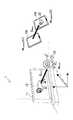
図11は、第1の操作シナリオに沿って、新たな仮想オブジェクトが基準環境内に配置される様子を示している。(1) First Operation Scenario FIG. 11 shows a state in which a new virtual object is arranged in the reference environment according to the first operation scenario.
図11の例において、基準環境1内の物体11は、デジタルテレビジョン装置である。デジタルテレビジョン装置11の画面には、ライオン12を映したコンテンツ画像が表示されている。物体DB150には、ライオン12の特徴量データが予め記憶されている。 In the example of FIG. 11, the
時刻t1において、ユーザが画像処理装置100をデジタルテレビジョン装置11にかざすと、入力画像にライオン12が映る。認識部130は、物体DB150により記憶されている特徴量データを用いて、入力画像に映るライオン12を識別する。すると、操作制御部170は、コンテンツDB160においてライオン12と関連付けられている仮想オブジェクト22を、操作対象の仮想オブジェクトとして特定する。仮想オブジェクト22は、例えば、並行移動可能であるものとする。 When the user holds the
その後、時刻t1から時刻t2にかけて、ユーザは、画像処理装置100の画面にタッチしながら、画像処理装置100を移動させる。すると、操作制御部170は、移動の前後の2つの操作配置行列Mmobile(t1)及びMmobile(t2)の間の並行移動成分の差分である並行移動操作量Dmovを計算する。そして、操作制御部170は、ライオン12の位置及び姿勢及び並行移動操作量Dmovから、操作後の仮想オブジェクト22の位置及び姿勢を表現する操作後行列Mpostを計算する。表示制御部180は、操作後行列Mpostにより表現される3次元的な位置及び姿勢を有する仮想オブジェクト22を2次元の画面に投影し、仮想オブジェクト22の重畳された出力画像を表示させる。Thereafter, from time t1 to time t2, the user moves the
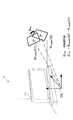
(2)第2の操作シナリオ
図12は、第2の操作シナリオに沿って、配置済みの仮想オブジェクトがユーザにより操作される様子を示している。(2) Second Operation Scenario FIG. 12 shows a state in which a virtual object that has been arranged is operated by the user according to the second operation scenario.
図12の例において、基準環境1内の物体11は、デジタルテレビジョン装置である。物体DB150には、デジタルテレビジョン装置11の特徴量データが予め記憶されている。また、コンテンツDB160には、デジタルテレビジョン装置11と関連付けられている仮想オブジェクト23のデータが予め記憶されている。仮想オブジェクト23は、例えば、デジタルテレビジョン装置11についての情報を表示する仮想的なパネルである。 In the example of FIG. 12, the
時刻t3において、仮想オブジェクト23は、操作前行列Mpreにより表現される位置及び姿勢でAR空間内に配置されている。ユーザが画像処理装置100をデジタルテレビジョン装置11にかざすと、入力画像に仮想オブジェクト23が映る。そして、ユーザが画面上で仮想オブジェクト23にタッチすると、操作制御部170は、仮想オブジェクト23を操作対象の仮想オブジェクトとして特定する。仮想オブジェクト23は、例えば、回転可能であるものとする。At time t3, the
その後、時刻t3から時刻t4にかけて、ユーザは、画像処理装置100を回転させる。すると、操作制御部170は、移動の前後の2つの操作配置行列Mmobile(t3)及びMmobile(t4)の間の回転成分の差分である回転操作量Drotを計算する。そして、操作制御部170は、操作前行列Mpre及び回転操作量Drotから計算される操作後行列Mpostにより表現される位置及び姿勢を仮想オブジェクト23が有するように、仮想オブジェクト23を再配置する。Thereafter, the user rotates the
[2−4.処理の流れ]
図13は、画像処理装置100による画像処理の流れの一例を示すフローチャートである。[2-4. Process flow]
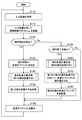
FIG. 13 is a flowchart illustrating an example of the flow of image processing by the
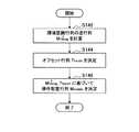
図13を参照すると、まず、画像取得部120は、撮像部102により生成される撮像画像を入力画像として取得する(ステップS110)。そして、画像取得部120は、取得した入力画像を、認識部130及び表示制御部180へ出力する。 Referring to FIG. 13, first, the
次に、認識部130は、画像取得部120から入力される入力画像を用いて、基準環境の位置及び姿勢を表現する環境認識行列Mrecogを認識する(ステップS115)。そして、認識部130は、認識した環境認識行列Mrecogを、計算部140、操作制御部170及び表示制御部180へ出力する。Next, the
次に、図13の画像処理は、操作状態に応じて分岐する。まず、ユーザにより所定の操作が開始されたことが検出された場合には、処理はステップS130へ進む(ステップS120)。また、ユーザにより開始された当該操作が終了したことが検出された場合には、処理はステップS160へ進む(ステップS125)。それ以外の場合には、処理はステップS190へ進む。 Next, the image processing in FIG. 13 branches according to the operation state. First, when it is detected that a predetermined operation is started by the user, the process proceeds to step S130 (step S120). If it is detected that the operation started by the user is completed, the process proceeds to step S160 (step S125). Otherwise, the process proceeds to step S190.
ステップS130では、操作制御部170は、操作対象の仮想オブジェクトを特定する(ステップS130)。ここで特定される仮想オブジェクトの数は、1つであってもよく、又は複数であってもよい。次に、図14を用いて説明される操作配置計算処理が実行され、第1の操作配置行列が計算される(ステップS140)。そして、計算された第1の操作配置行列が記憶される(ステップS150)。 In step S130, the
ステップS160では、図14を用いて説明される操作配置計算処理が実行され、第2の操作配置行列が計算される(ステップS160)。次に、操作制御部170は、第1及び第2の操作配置行列を用いて、操作対象の仮想オブジェクトの操作量を決定する(ステップS170)。そして、操作制御部170は、決定した操作量に従って、操作対象の仮想オブジェクトを再配置する(ステップS180)。 In step S160, the operation arrangement calculation process described with reference to FIG. 14 is executed, and a second operation arrangement matrix is calculated (step S160). Next, the
そして、表示制御部180は、操作対象の仮想オブジェクト及びその他の表示すべき仮想オブジェクトが重畳された出力画像を生成し、生成した出力画像を表示部110の画面に表示させる(ステップS190)。 The
図14は、図13のステップS140及びS160に相当する操作配置計算処理の詳細な流れの一例を示すフローチャートである。 FIG. 14 is a flowchart showing an example of a detailed flow of the operation arrangement calculation process corresponding to steps S140 and S160 of FIG.
図14を参照すると、まず、計算部140は、認識部130から入力される環境認識行列の逆行列Mrecog−1を計算する(ステップS142)。また、操作制御部170は、端末の画面上でのユーザ入力位置に応じて、オフセット行列Ttouchを決定する(ステップS144)。なお、オフセット行列が使用されない場合には、ステップS144の処理は省略されてもよい。そして、操作制御部170は、環境認識行列の逆行列Mrecog−1及びオフセット行列Ttouchに基づいて、操作配置行列Mmobileを決定する(ステップS146)。Referring to FIG. 14, first, the
[2−5.表示のバリエーション]
本開示に係る技術において、仮想オブジェクトは、様々な形態で表示され得る。本項では、仮想オブジェクトの様々な表示のバリエーションについて説明する。[2-5. Display variations]
In the technology according to the present disclosure, the virtual object may be displayed in various forms. In this section, various display variations of the virtual object will be described.
例えば、仮想オブジェクトは、予め定義される基準面を有してもよい。仮想オブジェクトがカード状の平面的な形状を有する場合には、一方の面が基準面、他方の面が非基準面として定義され得る。仮想オブジェクトが立体的な形状を有する場合には、当該仮想オブジェクトの基準面は、基準面から外へ向かう法線ベクトルによって識別され得る。このように仮想オブジェクトが基準面を有する場合、表示制御部180は、画像処理装置100の画面に当該仮想オブジェクトの基準面が映るか否かに応じて、当該仮想オブジェクトの表示を変化させてよい。 For example, the virtual object may have a predefined reference plane. When the virtual object has a card-like planar shape, one surface can be defined as a reference surface and the other surface as a non-reference surface. When the virtual object has a three-dimensional shape, the reference plane of the virtual object can be identified by a normal vector that goes outward from the reference plane. When the virtual object has the reference plane in this way, the
例えば、図15の例を参照すると、画像処理装置100の画面に表示される出力画像Im1に、2つの仮想オブジェクト31及び32が映っている。出力画像Im1に映っている仮想オブジェクト31の面は、非基準面である。出力画像Im1に映っている仮想オブジェクト32の面は、基準面である。従って、表示制御部180は、例えば、仮想オブジェクト32の形状、スケール、透明度、色、解像度又はエッジの太さなどの表示属性を、仮想オブジェクト31とは異なる値に設定し得る。また、表示制御部180は、仮想オブジェクト31及び32により示される情報の内容を、基準面が映っているか否かに応じて変化させてもよい。 For example, referring to the example of FIG. 15, two
このような表示の制御によって、表示される仮想オブジェクトがどの方向を向いているかをユーザが容易に把握することができる。このようなケースで、ユーザが仮想オブジェクト31の基準面に表示される情報の内容を閲覧したいと望んでいるものとする。本開示に係る技術がなければ、ユーザは、仮想オブジェクト31の基準面が見える位置に回りこんで端末をかざしてみることになる。しかし、本開示に係る技術によれば、ユーザは、画面上で仮想オブジェクト31を指定して端末をその場で回転させるだけで、仮想オブジェクト31の姿勢を3次元的に回転させ、仮想オブジェクト31の基準面に表示される情報の内容を容易に閲覧することができる。 By such display control, the user can easily grasp which direction the displayed virtual object is facing. In such a case, it is assumed that the user wants to browse the content of information displayed on the reference plane of the
また、表示制御部180は、画像処理装置100と仮想オブジェクトとの間の距離に応じて、当該仮想オブジェクトの表示を変化させてもよい。 The
例えば、図16の例を参照すると、画像処理装置100の画面に表示される出力画像Im2に3つの仮想オブジェクト41、42及び43が映っている。このうち、仮想オブジェクト43は、仮想オブジェクト41及び42と比較して、画像処理装置100からより遠くに位置する。この場合、表示制御部180は、例えば、仮想オブジェクト41及び42がより明瞭にユーザに視認されるように、仮想オブジェクト41及び42の表示属性を強調し得る。また、表示制御部180は、仮想オブジェクト41及び42について、より詳細な情報の内容を表示させてもよい。 For example, referring to the example of FIG. 16, three
このような表示の制御によって、多数の仮想オブジェクトが画面に表示されるような状況下で、ユーザがより関心を持っている(即ち、端末を近付けている)仮想オブジェクトの(又はその表示内容の)視認性を高めることができる。このようなケースで、ユーザが仮想オブジェクト43により表示される情報の内容をも詳しく閲覧したいと望んでいるものとする。本開示に係る技術がなければ、ユーザは、より仮想オブジェクト43に近付いた上で端末をかざしてみることになる。しかし、本開示に係る技術によれば、ユーザは、画面上で仮想オブジェクト43を指定して端末を引き寄せる動きをするだけで、仮想オブジェクト43の位置を手前に移動させ、仮想オブジェクト43により表示される情報の内容をより詳しく閲覧することができる。 Under such a situation where a large number of virtual objects are displayed on the screen by such display control, the virtual object (or the content of the display content) of the virtual object that the user is more interested in (that is, close to the terminal) is displayed. ) Visibility can be improved. In such a case, it is assumed that the user desires to browse the contents of information displayed by the
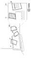
表示制御部180は、所定の条件が満たされる場合に、表示すべき複数の仮想オブジェクトが所定の間隔を空けて整列するように、当該複数の仮想オブジェクトを再配置してもよい。 The
例えば、図17の例を参照すると、画像処理装置100の画面に6つの仮想オブジェクト51〜56が映っている。しかし、これら仮想オブジェクトがその配置の通りに表示されると、画面内で仮想オブジェクトが密集してしまい、仮想オブジェクトの視認性が低下する。そこで、例えば、表示制御部180は、所定のユーザ入力が検出された場合に、これら仮想オブジェクトを整列させる。図17の例では、画像処理装置100のより近くに位置する4つの仮想オブジェクト51、52、53及び54が、所定の間隔を空けて整列するように再配置されている。仮想オブジェクトを再配置させるための上記所定の条件は、ユーザ入力の代わりに、例えば画面内の仮想オブジェクトの個数が所定の閾値を上回ることなどであってもよい。 For example, referring to the example of FIG. 17, six
このような表示の制御によって、多数の仮想オブジェクトが画面に表示されるような状況下で、仮想オブジェクトの各々が示す情報の内容の視認性を高めることができる。操作制御部170は、このように整列された仮想オブジェクトの操作を、上述した仕組みに従って制御してもよい。 By such display control, it is possible to improve the visibility of the contents of information indicated by each virtual object under a situation where a large number of virtual objects are displayed on the screen. The
[2−6.仮想オブジェクトの共有]
ここまでの説明では、仮想オブジェクトの操作に用いられる端末と操作される仮想オブジェクトを表示する端末とが同一であった。しかしながら、本開示に係る技術は、かかる例に限定されない。例えば、ある端末を用いて操作される仮想オブジェクトが、他の端末の画面に表示されてもよい。本項では、そのような仮想オブジェクトの共有について説明する。[2-6. Virtual object sharing]
In the description so far, the terminal used for operating the virtual object is the same as the terminal displaying the operated virtual object. However, the technology according to the present disclosure is not limited to such an example. For example, a virtual object operated using a certain terminal may be displayed on the screen of another terminal. In this section, sharing of such virtual objects will be described.
図18を参照すると、仮想オブジェクトをユーザ間で共有するための、画像処理装置100a及び画像処理装置100bを含む画像処理システムが示されている。 Referring to FIG. 18, an image processing system including an
例えば、画像処理装置100aは、上述した仕組みに従って、基準座標系CS2を有する基準環境2内で、ユーザによる操作に応じて仮想オブジェクトの配置を決定する。図18の例では、車を模した仮想オブジェクト61が実物体であるテーブル62の上に配置されている。仮想オブジェクト61は、例えば、画像処理装置100aにおいて決定される操作量(例えば、並行移動操作量Dmov)に従って移動可能である。画像処理装置100aは、仮想オブジェクト61の配置を表現するデータ(例えば、上述した操作後行列Mpost)を画像処理装置100bへ送信する。画像処理装置100bは、入力画像に映る基準環境2の位置及び姿勢を表現する環境認識行列を認識し、認識した環境認識行列と画像処理装置100aから受信される操作後行列Mpostとを用いて、仮想オブジェクト61を入力画像に重畳する。For example, the
図18の例では、基準環境として、テーブル62を含む1つの空間に相当する環境2が示されている。しかしながら、本開示に係る技術が適用される基準環境は、このような環境に限定されない。例えば、画像処理装置100aが存在する空間と画像処理装置100bが存在する空間とが異なる場合であっても、それら空間の間で共通する特徴点群若しくは物体が存在し、又は同視し得る校正された座標系が存在する場合には、それら空間に相当する複数の環境が1つの共通的な基準環境として扱われてよい。また、1つの空間において互いに異なる時刻に認識される環境が、1つの共通的な基準環境として扱われてもよい。 In the example of FIG. 18, the environment 2 corresponding to one space including the table 62 is shown as the reference environment. However, the reference environment to which the technology according to the present disclosure is applied is not limited to such an environment. For example, even when the space in which the
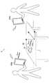
例えば、図19Aを参照すると、環境3a内に、画像処理装置100aと本63aとが存在する。図19Bを参照すると、環境3b内に、画像処理装置100bと本63bとが存在する。本63a及び本63bは、共通的な特徴点群を有する。従って、画像処理装置100a及び100bは、それら特徴点群を用いて1つの共通的な基準座標系CS3を認識し、基準座標系CS3と関連付けられる仮想オブジェクトを共有することができる。図19Aの例では、ゾウを模した仮想オブジェクト73が本63aの近傍に配置されている。仮想オブジェクト73は、例えば、画像処理装置100aにおいて決定される操作量(例えば、回転操作量Drot)に従って回転可能である。画像処理装置100bは、仮想オブジェクト73の配置を表現するデータ(例えば、上述した操作後行列Mpost)を画像処理装置100bへ送信する。画像処理装置100bは、入力画像に映る基準環境3bの位置及び姿勢を表現する環境認識行列を認識し、認識した環境認識行列と画像処理装置100aから受信される操作後行列Mpostとを用いて、仮想オブジェクト73の重畳された出力画像を表示する。For example, referring to FIG. 19A, the
<3.まとめ>
ここまで、図1〜図19Bを用いて、本開示に係る技術の一実施形態について詳細に説明した。上述した実施形態によれば、基準環境内の端末の位置及び姿勢を基準として環境の位置及び姿勢を表現する環境認識行列が認識され、認識された環境認識行列の逆行列に基づいて端末の位置及び姿勢が表現される。そして、2つの時点の端末の位置及び姿勢の一方又は双方の差分に応じた3次元的な操作量で、基準環境内に配置される仮想オブジェクトが操作される。従って、ユーザは、端末を3次元空間内で動かすことにより、AR空間内で仮想オブジェクトを3次元的に自在に操作することができる。例えば、携帯端末が使用される場合には、ユーザは、当該携帯端末を持って動かすことにより、仮想オブジェクトを3次元的に移動させ、及び仮想オブジェクトを3次元的に回転させることができる。<3. Summary>
Up to this point, an embodiment of the technology according to the present disclosure has been described in detail with reference to FIGS. According to the above-described embodiment, the environment recognition matrix expressing the position and orientation of the environment is recognized on the basis of the position and orientation of the terminal in the reference environment, and the position of the terminal is based on the inverse matrix of the recognized environment recognition matrix. And the posture is expressed. Then, the virtual object arranged in the reference environment is operated with a three-dimensional operation amount corresponding to the difference between one or both of the position and orientation of the terminal at two points in time. Therefore, the user can freely operate the virtual object in three dimensions in the AR space by moving the terminal in the three-dimensional space. For example, when a portable terminal is used, the user can move the virtual object three-dimensionally and rotate the virtual object three-dimensionally by holding and moving the portable terminal.
また、上述した実施形態によれば、一連の操作の開始時の画面上のユーザ入力位置に基づいて、操作対象の仮想オブジェクトが特定される。それにより、仮想オブジェクトを3次元空間内でドラッグして動かすような直感的なユーザインタフェースを実現することができる。 Further, according to the above-described embodiment, the virtual object to be operated is specified based on the user input position on the screen at the start of a series of operations. Thereby, an intuitive user interface in which a virtual object is dragged and moved in a three-dimensional space can be realized.
なお、本明細書において説明した各装置による一連の制御処理は、ソフトウェア、ハードウェア、及びソフトウェアとハードウェアとの組合せのいずれを用いて実現されてもよい。ソフトウェアを構成するプログラムは、例えば、各装置の内部又は外部に設けられる記憶媒体に予め格納される。そして、各プログラムは、例えば、実行時にRAM(Random Access Memory)に読み込まれ、CPUなどのプロセッサにより実行される。 Note that a series of control processing by each device described in this specification may be realized using any of software, hardware, and a combination of software and hardware. For example, a program constituting the software is stored in advance in a storage medium provided inside or outside each device. Each program is read into a RAM (Random Access Memory) at the time of execution and executed by a processor such as a CPU.
また、各装置の論理的機能の一部は、当該装置上に実装される代わりに、クラウドコンピューティング環境内に存在する装置上に実装されてもよい。その場合には、論理的機能の間でやり取りされる情報が、図9に例示した通信部112を介して装置間で送信され又は受信され得る。 Also, some of the logical functions of each device may be implemented on a device that exists in the cloud computing environment instead of being implemented on the device. In this case, information exchanged between logical functions can be transmitted or received between devices via the
以上、添付図面を参照しながら本開示の好適な実施形態について詳細に説明したが、本開示の技術的範囲はかかる例に限定されない。本開示の技術分野における通常の知識を有する者であれば、特許請求の範囲に記載された技術的思想の範疇内において、各種の変更例または修正例に想到し得ることは明らかであり、これらについても、当然に本開示の技術的範囲に属するものと了解される。 The preferred embodiments of the present disclosure have been described in detail above with reference to the accompanying drawings, but the technical scope of the present disclosure is not limited to such examples. It is obvious that a person having ordinary knowledge in the technical field of the present disclosure can come up with various changes or modifications within the scope of the technical idea described in the claims. Of course, it is understood that it belongs to the technical scope of the present disclosure.
なお、以下のような構成も本開示の技術的範囲に属する。
(1)
画像を撮像した端末の位置及び姿勢を基準として前記画像に映る環境の位置及び姿勢を表現する環境認識行列を認識する認識部と、
前記環境認識行列の逆行列を計算する計算部と、
第1の時点で認識される前記環境認識行列の前記逆行列に基づく第1の位置又は第1の姿勢と、後続する第2の時点で認識される前記環境認識行列の前記逆行列に基づく第2の位置又は第2の姿勢との間の差分に応じた3次元的な操作量で、前記環境内に配置される仮想オブジェクトの操作を制御する操作制御部と、
を備える画像処理装置。
(2)
前記操作量は、前記第1の位置と前記第2の位置との間の差分に応じた並行移動量である、前記(1)に記載の画像処理装置。
(3)
前記操作量は、前記第1の姿勢と前記第2の姿勢との間の差分に応じた回転量である、前記(1)に記載の画像処理装置。
(4)
前記第1の時点は、前記端末において第1のユーザ入力が検出された時点であり、
前記第2の時点は、前記端末において第2のユーザ入力が検出された時点である、
前記(1)〜(3)のいずれか1項に記載の画像処理装置。
(5)
前記第1のユーザ入力及び前記第2のユーザ入力は、一連の操作の開始及び終了にそれぞれ対応する、前記(4)に記載の画像処理装置。
(6)
前記第1の位置又は前記第2の位置は、前記端末の画面上でのユーザ入力位置に応じて当該画面に沿った方向にオフセットされる位置である、前記(4)又は前記(5)に記載の画像処理装置。
(7)
前記操作制御部は、前記第1のユーザ入力に基づいて、操作すべき前記仮想オブジェクトを特定する、前記(4)〜(6)のいずれか1項に記載の画像処理装置。
(8)
前記操作制御部は、前記第1のユーザ入力によって指定される前記環境内の物体と関連付けられる仮想オブジェクトを、操作すべき前記仮想オブジェクトとして特定する、前記(7)に記載の画像処理装置。
(9)
前記認識部、前記計算部及び前記操作制御部のうち少なくとも1つが前記画像処理装置の代わりにクラウドコンピューティング環境上に存在する装置により実現される、前記(1)〜(8)のいずれか1項に記載の画像処理装置。
(10)
画像を撮像した端末の位置及び姿勢を基準として前記画像に映る環境の位置及び姿勢を表現する環境認識行列を認識することと、
前記環境認識行列の逆行列を計算することと、
第1の時点で認識される前記環境認識行列の前記逆行列に基づく第1の位置又は第1の姿勢と、後続する第2の時点で認識される前記環境認識行列の前記逆行列に基づく第2の位置又は第2の姿勢との間の差分に応じた3次元的な操作量で、前記環境内に配置される仮想オブジェクトの操作を制御することと、
を含む画像処理方法。
(11)
コンピュータを、
画像を撮像した端末の位置及び姿勢を基準として前記画像に映る環境の位置及び姿勢を表現する環境認識行列を認識する認識部と、
前記環境認識行列の逆行列を計算する計算部と、
第1の時点で認識される前記環境認識行列の前記逆行列に基づく第1の位置又は第1の姿勢と、後続する第2の時点で認識される前記環境認識行列の前記逆行列に基づく第2の位置又は第2の姿勢との間の差分に応じた3次元的な操作量で、前記環境内に配置される仮想オブジェクトの操作を制御する操作制御部と、
として機能させるためのプログラム。The following configurations also belong to the technical scope of the present disclosure.
(1)
A recognition unit for recognizing an environment recognition matrix expressing the position and orientation of the environment reflected in the image based on the position and orientation of the terminal that captured the image;
A calculation unit for calculating an inverse matrix of the environment recognition matrix;
A first position or first attitude based on the inverse matrix of the environment recognition matrix recognized at a first time point, and a first position based on the inverse matrix of the environment recognition matrix recognized at a subsequent second time point. An operation control unit that controls an operation of a virtual object arranged in the environment with a three-dimensional operation amount according to a difference between the position of 2 or the second posture;
An image processing apparatus comprising:
(2)
The image processing apparatus according to (1), wherein the operation amount is a parallel movement amount corresponding to a difference between the first position and the second position.
(3)
The image processing apparatus according to (1), wherein the operation amount is a rotation amount corresponding to a difference between the first posture and the second posture.
(4)
The first time point is a time point when a first user input is detected at the terminal;
The second time point is a time point when a second user input is detected at the terminal.
The image processing apparatus according to any one of (1) to (3).
(5)
The image processing apparatus according to (4), wherein the first user input and the second user input correspond to start and end of a series of operations, respectively.
(6)
In the above (4) or (5), the first position or the second position is a position that is offset in a direction along the screen according to a user input position on the screen of the terminal. The image processing apparatus described.
(7)
The image processing apparatus according to any one of (4) to (6), wherein the operation control unit specifies the virtual object to be operated based on the first user input.
(8)
The image processing apparatus according to (7), wherein the operation control unit specifies a virtual object associated with an object in the environment specified by the first user input as the virtual object to be operated.
(9)
Any one of (1) to (8), wherein at least one of the recognition unit, the calculation unit, and the operation control unit is realized by a device that exists in a cloud computing environment instead of the image processing device. The image processing apparatus according to item.
(10)
Recognizing an environment recognition matrix expressing the position and orientation of the environment shown in the image based on the position and orientation of the terminal that captured the image;
Calculating an inverse matrix of the environment recognition matrix;
A first position or first attitude based on the inverse matrix of the environment recognition matrix recognized at a first time point, and a first position based on the inverse matrix of the environment recognition matrix recognized at a subsequent second time point. Controlling the operation of the virtual object arranged in the environment with a three-dimensional operation amount corresponding to the difference between the position 2 or the second posture;
An image processing method including:
(11)
Computer
A recognition unit for recognizing an environment recognition matrix expressing the position and orientation of the environment reflected in the image based on the position and orientation of the terminal that captured the image;
A calculation unit for calculating an inverse matrix of the environment recognition matrix;
A first position or first attitude based on the inverse matrix of the environment recognition matrix recognized at a first time point, and a first position based on the inverse matrix of the environment recognition matrix recognized at a subsequent second time point. An operation control unit that controls an operation of a virtual object arranged in the environment with a three-dimensional operation amount according to a difference between the position of 2 or the second posture;
Program to function as.
100 画像処理装置(端末)
120 画像取得部
130 認識部
140 計算部
170 操作制御部
180 表示制御部
100 Image processing device (terminal)
120
Claims (11)
Translated fromJapanese前記環境認識行列の逆行列を計算する計算部と、
第1の時点で認識される前記環境認識行列の前記逆行列に基づく第1の位置又は第1の姿勢と、後続する第2の時点で認識される前記環境認識行列の前記逆行列に基づく第2の位置又は第2の姿勢との間の差分に応じた3次元的な操作量で、前記環境内に配置される仮想オブジェクトの操作を制御する操作制御部と、
を備える画像処理装置。A recognition unit for recognizing an environment recognition matrix expressing the position and orientation of the environment reflected in the image based on the position and orientation of the terminal that captured the image;
A calculation unit for calculating an inverse matrix of the environment recognition matrix;
A first position or first attitude based on the inverse matrix of the environment recognition matrix recognized at a first time point, and a first position based on the inverse matrix of the environment recognition matrix recognized at a subsequent second time point. An operation control unit that controls an operation of a virtual object arranged in the environment with a three-dimensional operation amount according to a difference between the position of 2 or the second posture;
An image processing apparatus comprising:
前記第2の時点は、前記端末において第2のユーザ入力が検出された時点である、
請求項1〜3のいずれか1項に記載の画像処理装置。The first time point is a time point when a first user input is detected at the terminal;
The second time point is a time point when a second user input is detected at the terminal.
The image processing apparatus according toany one of claims 1 to3 .
前記環境認識行列の逆行列を計算することと、
第1の時点で認識される前記環境認識行列の前記逆行列に基づく第1の位置又は第1の姿勢と、後続する第2の時点で認識される前記環境認識行列の前記逆行列に基づく第2の位置又は第2の姿勢との間の差分に応じた3次元的な操作量で、前記環境内に配置される仮想オブジェクトの操作を制御することと、
を含む画像処理方法。Recognizing an environment recognition matrix expressing the position and orientation of the environment shown in the image based on the position and orientation of the terminal that captured the image;
Calculating an inverse matrix of the environment recognition matrix;
A first position or first attitude based on the inverse matrix of the environment recognition matrix recognized at a first time point, and a first position based on the inverse matrix of the environment recognition matrix recognized at a subsequent second time point. Controlling the operation of the virtual object arranged in the environment with a three-dimensional operation amount corresponding to the difference between the position 2 or the second posture;
An image processing method including:
画像を撮像した端末の位置及び姿勢を基準として前記画像に映る環境の位置及び姿勢を表現する環境認識行列を認識する認識部と、
前記環境認識行列の逆行列を計算する計算部と、
第1の時点で認識される前記環境認識行列の前記逆行列に基づく第1の位置又は第1の姿勢と、後続する第2の時点で認識される前記環境認識行列の前記逆行列に基づく第2の位置又は第2の姿勢との間の差分に応じた3次元的な操作量で、前記環境内に配置される仮想オブジェクトの操作を制御する操作制御部と、
として機能させるためのプログラム。Computer
A recognition unit for recognizing an environment recognition matrix expressing the position and orientation of the environment reflected in the image based on the position and orientation of the terminal that captured the image;
A calculation unit for calculating an inverse matrix of the environment recognition matrix;
A first position or first attitude based on the inverse matrix of the environment recognition matrix recognized at a first time point, and a first position based on the inverse matrix of the environment recognition matrix recognized at a subsequent second time point. An operation control unit that controls an operation of a virtual object arranged in the environment with a three-dimensional operation amount according to a difference between the position of 2 or the second posture;
Program to function as.
Priority Applications (1)
| Application Number | Priority Date | Filing Date | Title |
|---|---|---|---|
| JP2013557372AJP5807686B2 (en) | 2012-02-10 | 2012-11-29 | Image processing apparatus, image processing method, and program |
Applications Claiming Priority (4)
| Application Number | Priority Date | Filing Date | Title |
|---|---|---|---|
| JP2012026870 | 2012-02-10 | ||
| JP2012026870 | 2012-02-10 | ||
| JP2013557372AJP5807686B2 (en) | 2012-02-10 | 2012-11-29 | Image processing apparatus, image processing method, and program |
| PCT/JP2012/080863WO2013118373A1 (en) | 2012-02-10 | 2012-11-29 | Image processing apparatus, image processing method, and program |
Publications (2)
| Publication Number | Publication Date |
|---|---|
| JPWO2013118373A1 JPWO2013118373A1 (en) | 2015-05-11 |
| JP5807686B2true JP5807686B2 (en) | 2015-11-10 |
Family
ID=48947160
Family Applications (1)
| Application Number | Title | Priority Date | Filing Date |
|---|---|---|---|
| JP2013557372AExpired - Fee RelatedJP5807686B2 (en) | 2012-02-10 | 2012-11-29 | Image processing apparatus, image processing method, and program |
Country Status (5)
| Country | Link |
|---|---|
| US (1) | US9268410B2 (en) |
| EP (1) | EP2814000B1 (en) |
| JP (1) | JP5807686B2 (en) |
| CN (1) | CN104081307B (en) |
| WO (1) | WO2013118373A1 (en) |
Families Citing this family (32)
| Publication number | Priority date | Publication date | Assignee | Title |
|---|---|---|---|---|
| JP6263917B2 (en)* | 2013-09-17 | 2018-01-24 | ソニー株式会社 | Information processing apparatus, information processing method, and computer program |
| WO2015107625A1 (en)* | 2014-01-15 | 2015-07-23 | 日立マクセル株式会社 | Information display terminal, information display system, and information display method |
| US9690370B2 (en)* | 2014-05-05 | 2017-06-27 | Immersion Corporation | Systems and methods for viewport-based augmented reality haptic effects |
| JP6575221B2 (en)* | 2015-08-19 | 2019-09-18 | 富士通株式会社 | Display control method, information processing apparatus, and display control program |
| US10101803B2 (en)* | 2015-08-26 | 2018-10-16 | Google Llc | Dynamic switching and merging of head, gesture and touch input in virtual reality |
| CN105913495A (en)* | 2016-03-31 | 2016-08-31 | 联想(北京)有限公司 | Information processing method and electronic equipment |
| CN106200916B (en)* | 2016-06-28 | 2019-07-02 | Oppo广东移动通信有限公司 | Augmented reality image control method, device and terminal device |
| EP3327544B1 (en)* | 2016-11-25 | 2021-06-23 | Nokia Technologies Oy | Apparatus, associated method and associated computer readable medium |
| DK180470B1 (en)* | 2017-08-31 | 2021-05-06 | Apple Inc | Systems, procedures, and graphical user interfaces for interacting with augmented and virtual reality environments |
| EP3599539B1 (en)* | 2018-07-26 | 2023-08-23 | Nokia Technologies Oy | Rendering objects in virtual views |
| US10909772B2 (en) | 2018-07-31 | 2021-02-02 | Splunk Inc. | Precise scaling of virtual objects in an extended reality environment |
| US10692299B2 (en) | 2018-07-31 | 2020-06-23 | Splunk Inc. | Precise manipulation of virtual object position in an extended reality environment |
| JP7260763B2 (en)* | 2019-03-26 | 2023-04-19 | 株式会社Mixi | Information processing device and program |
| JP2022505998A (en)* | 2019-10-15 | 2022-01-17 | ベイジン センスタイム テクノロジー デベロップメント カンパニー, リミテッド | Augmented reality data presentation methods, devices, electronic devices and storage media |
| WO2021221676A1 (en)* | 2020-04-30 | 2021-11-04 | Hewlett-Packard Development Company, L.P. | Frames of reference |
| AU2021347112B2 (en) | 2020-09-25 | 2023-11-23 | Apple Inc. | Methods for manipulating objects in an environment |
| KR20230054733A (en) | 2020-09-25 | 2023-04-25 | 애플 인크. | Methods for interacting with virtual controls and/or affordance for moving virtual objects in virtual environments |
| CN117555417B (en) | 2020-09-25 | 2024-07-19 | 苹果公司 | Method for adjusting and/or controlling immersion associated with a user interface |
| CN116670627A (en) | 2020-12-31 | 2023-08-29 | 苹果公司 | Methods for Grouping User Interfaces in Environments |
| CN113674430A (en)* | 2021-08-24 | 2021-11-19 | 上海电气集团股份有限公司 | Virtual model positioning and registering method and device, augmented reality equipment and storage medium |
| EP4388397A1 (en) | 2021-09-25 | 2024-06-26 | Apple Inc. | Devices, methods, and graphical user interfaces for presenting virtual objects in virtual environments |
| EP4398073A4 (en)* | 2021-10-12 | 2024-12-11 | Sony Group Corporation | INFORMATION PROCESSING SYSTEM, CONTROL METHOD AND CONTROL PROGRAM |
| AU2023209446A1 (en)* | 2022-01-19 | 2024-08-29 | Apple Inc. | Methods for displaying and repositioning objects in an environment |
| US12272005B2 (en) | 2022-02-28 | 2025-04-08 | Apple Inc. | System and method of three-dimensional immersive applications in multi-user communication sessions |
| WO2023196258A1 (en) | 2022-04-04 | 2023-10-12 | Apple Inc. | Methods for quick message response and dictation in a three-dimensional environment |
| US12394167B1 (en) | 2022-06-30 | 2025-08-19 | Apple Inc. | Window resizing and virtual object rearrangement in 3D environments |
| US12112011B2 (en) | 2022-09-16 | 2024-10-08 | Apple Inc. | System and method of application-based three-dimensional refinement in multi-user communication sessions |
| US12148078B2 (en) | 2022-09-16 | 2024-11-19 | Apple Inc. | System and method of spatial groups in multi-user communication sessions |
| US12099653B2 (en) | 2022-09-22 | 2024-09-24 | Apple Inc. | User interface response based on gaze-holding event assessment |
| US12405704B1 (en) | 2022-09-23 | 2025-09-02 | Apple Inc. | Interpreting user movement as direct touch user interface interactions |
| US12118200B1 (en) | 2023-06-02 | 2024-10-15 | Apple Inc. | Fuzzy hit testing |
| US12113948B1 (en) | 2023-06-04 | 2024-10-08 | Apple Inc. | Systems and methods of managing spatial groups in multi-user communication sessions |
Family Cites Families (10)
| Publication number | Priority date | Publication date | Assignee | Title |
|---|---|---|---|---|
| JP3558104B2 (en) | 1996-08-05 | 2004-08-25 | ソニー株式会社 | Three-dimensional virtual object display apparatus and method |
| JP3944019B2 (en) | 2002-07-31 | 2007-07-11 | キヤノン株式会社 | Information processing apparatus and method |
| WO2006025137A1 (en)* | 2004-09-01 | 2006-03-09 | Sony Computer Entertainment Inc. | Image processor, game machine, and image processing method |
| JP2009093376A (en)* | 2007-10-05 | 2009-04-30 | Sony Corp | Signal processing system, signal processing method, and program |
| JP5315111B2 (en)* | 2009-03-31 | 2013-10-16 | 株式会社エヌ・ティ・ティ・ドコモ | Terminal device, information presentation system, and terminal screen display method |
| US20100257252A1 (en) | 2009-04-01 | 2010-10-07 | Microsoft Corporation | Augmented Reality Cloud Computing |
| JP4696184B1 (en)* | 2010-06-02 | 2011-06-08 | 任天堂株式会社 | Image display system, image display apparatus, and image display method |
| US8633947B2 (en) | 2010-06-02 | 2014-01-21 | Nintendo Co., Ltd. | Computer-readable storage medium having stored therein information processing program, information processing apparatus, information processing system, and information processing method |
| EP2395768B1 (en)* | 2010-06-11 | 2015-02-25 | Nintendo Co., Ltd. | Image display program, image display system, and image display method |
| US20120200667A1 (en)* | 2011-02-08 | 2012-08-09 | Gay Michael F | Systems and methods to facilitate interactions with virtual content |
- 2012
- 2012-11-29WOPCT/JP2012/080863patent/WO2013118373A1/enactiveApplication Filing
- 2012-11-29CNCN201280068780.2Apatent/CN104081307B/enactiveActive
- 2012-11-29EPEP12868009.7Apatent/EP2814000B1/ennot_activeNot-in-force
- 2012-11-29USUS14/358,459patent/US9268410B2/enactiveActive
- 2012-11-29JPJP2013557372Apatent/JP5807686B2/ennot_activeExpired - Fee Related
Also Published As
| Publication number | Publication date |
|---|---|
| EP2814000B1 (en) | 2019-07-03 |
| WO2013118373A1 (en) | 2013-08-15 |
| US20140320404A1 (en) | 2014-10-30 |
| EP2814000A4 (en) | 2015-10-28 |
| CN104081307A (en) | 2014-10-01 |
| JPWO2013118373A1 (en) | 2015-05-11 |
| US9268410B2 (en) | 2016-02-23 |
| CN104081307B (en) | 2018-02-23 |
| EP2814000A1 (en) | 2014-12-17 |
Similar Documents
| Publication | Publication Date | Title |
|---|---|---|
| JP5807686B2 (en) | Image processing apparatus, image processing method, and program | |
| JP5942456B2 (en) | Image processing apparatus, image processing method, and program | |
| Kim et al. | Touch and hand gesture-based interactions for directly manipulating 3D virtual objects in mobile augmented reality | |
| JP6469706B2 (en) | Modeling structures using depth sensors | |
| US9591295B2 (en) | Approaches for simulating three-dimensional views | |
| CN104838337B (en) | Touchless input for user interface | |
| JP6458371B2 (en) | Method for obtaining texture data for a three-dimensional model, portable electronic device, and program | |
| JP2013164697A (en) | Image processing device, image processing method, program and image processing system | |
| JP6433923B2 (en) | Providing a specific object location to the device | |
| JP2013165366A (en) | Image processing device, image processing method, and program | |
| KR101470757B1 (en) | Method and apparatus for providing augmented reality service | |
| CN104346085A (en) | Control object operation method and device and terminal device | |
| CN114327063B (en) | Interaction method and device of target virtual object, electronic equipment and storage medium | |
| US10073612B1 (en) | Fixed cursor input interface for a computer aided design application executing on a touch screen device | |
| CN116185205B (en) | Non-contact gesture interaction method and device | |
| JP6304305B2 (en) | Image processing apparatus, image processing method, and program | |
| US10496237B2 (en) | Computer-implemented method for designing a three-dimensional modeled object | |
| KR101558094B1 (en) | Multi-modal system using for intuitive hand motion and control method thereof | |
| WO2021121061A1 (en) | Method for configuring spatial position of virtual object, and electronic device | |
| CN119225532A (en) | Display device control method and device based on gesture, storage medium, and device | |
| CN117453037A (en) | Interactive method, head display device, electronic device and readable storage medium | |
| CN114565819A (en) | A remote control method, device, equipment and storage medium |
Legal Events
| Date | Code | Title | Description |
|---|---|---|---|
| TRDD | Decision of grant or rejection written | ||
| A01 | Written decision to grant a patent or to grant a registration (utility model) | Free format text:JAPANESE INTERMEDIATE CODE: A01 Effective date:20150811 | |
| A61 | First payment of annual fees (during grant procedure) | Free format text:JAPANESE INTERMEDIATE CODE: A61 Effective date:20150824 | |
| R151 | Written notification of patent or utility model registration | Ref document number:5807686 Country of ref document:JP Free format text:JAPANESE INTERMEDIATE CODE: R151 | |
| R250 | Receipt of annual fees | Free format text:JAPANESE INTERMEDIATE CODE: R250 | |
| R250 | Receipt of annual fees | Free format text:JAPANESE INTERMEDIATE CODE: R250 | |
| R250 | Receipt of annual fees | Free format text:JAPANESE INTERMEDIATE CODE: R250 | |
| LAPS | Cancellation because of no payment of annual fees |