JP5807577B2 - Deposit / withdrawal equipment - Google Patents
Deposit / withdrawal equipmentDownload PDFInfo
- Publication number
- JP5807577B2 JP5807577B2JP2012027104AJP2012027104AJP5807577B2JP 5807577 B2JP5807577 B2JP 5807577B2JP 2012027104 AJP2012027104 AJP 2012027104AJP 2012027104 AJP2012027104 AJP 2012027104AJP 5807577 B2JP5807577 B2JP 5807577B2
- Authority
- JP
- Japan
- Prior art keywords
- withdrawal
- deposit
- register
- pattern
- identification information
- Prior art date
- Legal status (The legal status is an assumption and is not a legal conclusion. Google has not performed a legal analysis and makes no representation as to the accuracy of the status listed.)
- Active
Links
- 238000003860storageMethods0.000claimsdescription80
- 238000000034methodMethods0.000claimsdescription72
- 238000012937correctionMethods0.000claimsdescription71
- 230000008569processEffects0.000claimsdescription70
- 238000000151depositionMethods0.000claimsdescription11
- 230000008859changeEffects0.000description31
- 230000002776aggregationEffects0.000description27
- 238000004220aggregationMethods0.000description27
- 238000010586diagramMethods0.000description15
- 230000006870functionEffects0.000description8
- 238000011084recoveryMethods0.000description4
- 230000004044responseEffects0.000description4
- 238000012790confirmationMethods0.000description3
- 230000014759maintenance of locationEffects0.000description2
- 230000004931aggregating effectEffects0.000description1
- 238000009826distributionMethods0.000description1
- 230000000694effectsEffects0.000description1
- 230000002265preventionEffects0.000description1
- 238000000926separation methodMethods0.000description1
- 230000009466transformationEffects0.000description1
Images


Landscapes
- Cash Registers Or Receiving Machines (AREA)
Description
Translated fromJapanese本発明は、入出金装置に関するものであり、例えば、店舗が取り扱う現金を集計して、少なくともシフト毎の集計を行なう入出金装置に適用し得るものである。The present invention relatesto a depositing and dispensingequipment, for example, by aggregating the cash store handled, it is capable of applying to the depositing and dispensing unit for performing aggregation of at least each shift.
特許文献1には、従来の入出金装置に関する技術が記載されている。従来、店舗等にあるレジスタには、予めレジスタカードが割り当てられている。レジスタ担当者又は管理者は、担当するレジスタのレジスタカードを用いて入出金装置から釣銭を出金してレジスタにセットし、又レジスタ担当者のシフトが終了した後、レジスタにある現金を入出金装置に入金処理を行なっている。売上集計は、レジスタからの全入金額から釣銭出金額を差し引くことで求まる。
なお、レジスタは、レジスタカード、レジスタ担当者識別カード(IDカード)等によって紐付することができるので、レジスタの識別は、レジスタカード、レジスタ担当者識別カード等によっても行うことができる。 Since the register can be associated with a register card, a register person identification card (ID card), etc., the register can be identified with a register card, a register person identification card, or the like.
また、従来の売上集計や違算算出は、レジスタカードの識別情報に、レジスタ番号、出金金額及び入金金額、レジスタ担当者の識別番号等を対応付けて管理される。これにより、レジスタ毎、レジスタ担当者毎、又はレジスタカード毎の売上集計や違算算出が求まる。 Further, the conventional sales aggregation and miscalculation calculation are managed by associating the register card identification information with the register number, the withdrawal amount and the deposit amount, the identification number of the register person in charge, and the like. As a result, sales totalization or miscalculation calculation is obtained for each register, each register person, or each register card.
ところで、小売業者等は、レジスタ毎、レジスタを担当するシフト毎に、売上集計、違算算出を行なうが一般的であり、レジスタ毎、シフト毎に売上集計や違算算出を行なうことが強く求められている。 By the way, retailers, etc., generally calculate sales and miscalculation for each register and each shift in charge of the register, and are generally required to perform sales aggregation and miscalculation for each register and every shift. Yes.
しかしながら、従来の入出金装置は、各レジスタを担当するシフト毎の売上集計や違算算出を行なうことができなかった。 However, the conventional deposit / withdrawal device has not been able to perform sales aggregation or miscalculation for each shift in charge of each register.
そのため、従来は、レジ担当者がレジスタ毎のレジスタカードをシフト毎に使い分けて、レジスタカードに基づいて集計を行なっている。このように、レジ担当者がレジスタカードをシフト毎に使い分けて行なう場合、次のような課題が生じ得る。 For this reason, conventionally, a cashier in charge uses a register card for each register for each shift, and performs aggregation based on the register card. As described above, when the cashier person uses the register card for each shift, the following problems may occur.
まず、1台のレジスタに対して複数のシフトが割り当てられ、シフト毎に集計を行なう場合、レジスタを空けないようにするため、最低でもレジスタカードを2枚以上使用する必要がある。例えば、1台のレジスタに対して「Aカード」→「Bカード」→「Aカード」→…等のようにシフト毎にレジスタカードを使い分けている。このよう場合、複数枚のレジスタカードを用意するためのコストがかかってしまうという問題がある。 First, when a plurality of shifts are assigned to one register and aggregation is performed for each shift, it is necessary to use at least two register cards in order to prevent the registers from being freed. For example, a register card is used for each shift, such as “A card” → “B card” → “A card” →. In such a case, there is a problem that it takes a cost to prepare a plurality of register cards.
次に、1台のレジスタに対して複数のレジスタカードでシフト毎に切り替えて使用する場合、前のシフトのレジスタ担当者が入金処理の忘れることがある。この場合、前のシフトのレジ担当者が入金処理を行なうと、現在のシフトのレジ担当者の入金処理として扱われてしまうため、正確な集計ができないという問題がある。 Next, in the case of using a plurality of register cards for each register and switching each shift, the person in charge of registering the previous shift may forget the deposit process. In this case, if the cashier in charge of the previous shift performs the deposit processing, it is handled as the deposit processing of the cashier in charge of the current shift, so that there is a problem that accurate counting cannot be performed.
さらに、従来の入出金装置は、1枚のレジスタカードに、複数のシフトで出金するパターン出金の設定情報(パターン)を予め設定することができる。ここで、パターン出金とは、出金に係る金種及び各金種の枚数を予め設定して釣銭出金することをいう。上記のように、1枚のレジスタカードに、複数の設定情報(パターン)を設定することができるので、レジ担当者が、間違えて他のパターンを選択してしまうことがある。 Further, the conventional deposit / withdrawal apparatus can preset pattern withdrawal setting information (pattern) for withdrawal with a plurality of shifts on one register card. Here, the pattern withdrawal means that the denomination related to the withdrawal and the number of each denomination are set in advance and the change is dispensed. As described above, since a plurality of setting information (patterns) can be set in one register card, the cashier person may mistakenly select another pattern.
そのため、レジスタを担当するシフトを売上集計の1単位とし、シフト毎に売上集計を行なうことができる入出金装置が求められている。Therefore, a shift in charge of the register and one unit of the sales totalization, withdrawalequipment capable of performing sales totalizationare required for each shift.
かかる課題を解決するために、第1の本発明は、(1)予め決められた金種及び枚数を出金させる複数の出金パターンを記憶する出金パターン記憶手段と、(2)少なくとも、レジスタへの出金又はレジスタからの入金に用いられる媒体の媒体識別情報に、出金情報及び又は入金情報を対応付けて記憶する入出金情報記憶手段と、(3)複数の出金パターンの中から選択された出金パターンで出金処理を行なうものであって、選択された出金パターンで出金した出金情報を、取得した媒体識別情報に対応付けて入出金情報記憶手段に記憶させる出金処理手段と、(4)レジスタからの入金情報を取得し、入金情報を、取得した媒体識別情報に対応付けて入出金記憶手段に記憶させる入金処理手段と、(5)入出金情報記憶手段を参照して、媒体識別情報毎に、出金パターンで出金するパターン出金がされてから最終入金がされるまでを1集計単位として集計処理を行なう集計処理手段と、(5)集計処理手段により形成される媒体識別情報の集計単位毎に、出金情報及び又は入金情報の内容の訂正要求を受け付け、要求された内容で訂正を行なう訂正処理手段とを備えることを特徴とする入出金装置である。In order to solve such a problem, the first aspect of the present invention includes (1) a withdrawal pattern storage means for storing a plurality of withdrawal patterns for dispensing a predetermined denomination and number, and (2) at least, Deposit / withdrawal information storage means for storing the withdrawal information and / or the deposit information in association with the medium identification information of the medium used for withdrawal to / from the register, and (3) among a plurality of withdrawal patterns Withdrawing processing is performed with the withdrawal pattern selected from the above, and the withdrawal information withdrawn with the selected withdrawal pattern is stored in the deposit / withdrawal information storage means in association with the acquired medium identification information. (4) deposit processing means for acquiring deposit information from the register and storing the deposit information in the deposit / withdrawal storage means in association with the acquired medium identification information; and (5) deposit / withdrawal information storage. Refer to the means, medium For each identification information, and aggregate processing means for performing aggregation processing from being the dispensed pattern dispensed by the dispensing pattern until the final payment is as a countingunit, medium formed by (5) aggregation processing means A depositing / withdrawing apparatus comprisingcorrection processing means for accepting a request for correcting the contents of the withdrawal information and / or the depositing information and correcting the requested contents for each unit of identification information .
第2の本発明は、(1)予め決められた金種及び枚数を出金させる複数の出金パターンを記憶する出金パターン記憶手段と、(2)少なくとも、レジスタへの出金又はレジスタからの入金に用いられる媒体の媒体識別情報に、出金情報及び又は入金情報を対応付けて記憶する入出金情報記憶手段と、(3)複数の出金パターンの中から選択された出金パターンで出金処理を行なうものであって、選択された出金パターンで出金した出金情報を、取得した媒体識別情報に対応付けて入出金情報記憶手段に記憶させる出金処理手段と、(4)レジスタからの入金情報を取得し、入金情報を、取得した媒体識別情報に対応付けて入出金記憶手段に記憶させる入金処理手段と、(5)入出金情報記憶手段を参照して、媒体識別情報毎に、出金パターンで出金するパターン出金がされてから最終入金がされるまでを1集計単位として集計処理を行なう集計処理手段とを備え、出金処理手段が、選択された出金パターンで出金処理を行なう際に、取得した媒体識別情報について、既にパターン出金がなされており、最終入金が完結していないとき、選択された出金パターンの出金処理を行なわないことを特徴とする入出金装置である。The second aspect of the present invention is:(1) a withdrawal pattern storage means for storing a plurality of withdrawal patterns for dispensing a predetermined denomination and number, and (2) at least from withdrawal to a register or from a register. A deposit / withdrawal information storage means for storing the withdrawal information and / or the deposit information in association with the medium identification information of the medium used for depositing, and (3) a withdrawal pattern selected from a plurality of withdrawal patterns A withdrawal processing means for performing withdrawal processing, wherein withdrawal information withdrawn with the selected withdrawal pattern is stored in the withdrawal information storage means in association with the acquired medium identification information; (4 ) Deposit processing means for acquiring deposit information from the register and storing the deposit information in the deposit / withdrawal storage means in association with the acquired medium identification information; and (5) medium identification with reference to the deposit / withdrawal information storage means Withdrawal pattern for each information And a totaling processing means for performing a totaling process for a period from when the pattern is withdrawn until the final deposit is made, and the withdrawal processing means performs the withdrawal processing with the selected withdrawal pattern. When performing, with regard to the acquired medium identification information, when the pattern has already been withdrawn and the final deposit has not been completed, the withdrawal process of the selected withdrawal pattern is not performed. It is.
本発明によれば、レジスタを担当するシフトを売上集計の1単位とし、シフト毎に売上集計を行なうことができる。 According to the present invention, the shift in charge of the register is set as one unit of sales total, and the sales total can be performed for each shift.
(A)第1の実施形態
以下では、本発明の入出金装置の主たる実施形態を、図面を参照しながら詳細に説明する。(A) In the following first embodiment, the principal embodimentof the depositing and dispensingequipment of the present invention will be described in detail with reference to the drawings.
この実施形態は、店舗のレジスタに対して釣銭出金及び売上入金を管理する入出金装置に本発明を適用する場合を例示する。 This embodiment exemplifies a case where the present invention is applied to a deposit / withdrawal apparatus that manages change withdrawal and sales deposit with respect to a store register.
(A−1)実施形態の構成
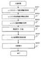
(A−1−1)入出金装置10の全体構成
図2は、実施形態に係る入出金装置10の外観斜視図である。また、図1は、実施形態に係る入出金装置10の内部構成を示す内部構成図である。(A-1) Configuration of Embodiment (A-1-1) Overall Configuration of Deposit /
入出金装置10は、例えば、ある店舗に設けられたレジスタが取り扱う現金を管理したり、また例えば、ショッピングセンタ等のように複数のショップからなる大規模な店舗において、各ショップのレジスタが取り扱う現金だけでなく、ショップ毎の現金を管理したりするものである。 The deposit /
図1において、入出金装置10は、大別して、硬貨処理機1、紙幣処理機2、表示部3、操作部4、カードリーダ5、伝票記録部6、記録部7、主制御部8を少なくとも有して構成される。 In FIG. 1, the deposit /
表示部3は、例えばLCD等により、入出金装置10の各種の処理操作の案内、入力画面、入力情報、金種別の入金金額又は出金金額等を表示する表示手段である。 The display unit 3 is a display unit that displays various processing operation guides, input screens, input information, deposit amounts or withdrawal amounts of money types, for example, on an LCD or the like.
操作部4は、レジスタの現金を入出金するレジスタ担当者や売上の締めを行なう店長等の管理者が操作するものである。また、操作部4は、後述する入出金処理を行なうために、パターン出金の入力、シフト設定の入力、訂正処理の入力等を行なう際に、レジスタ担当者や管理者等が操作するものである。操作部4は、例えば、キーボードやテンキーなどの物理的な入力手段や、表示部3上に配置されたタッチパネル等の入力手段を適用することができる。 The
カードリーダ5は、入出金装置10の利用者であるレジスタ担当者や管理者等が使用するIDカードの情報を読み取るものである。ここで、IDカードとしては、管理者が用いる管理カード、レジスタの担当者が用いるレジスタカード、店舗毎に発行された店舗カード等がある。 The
伝票記録部6は、硬貨処理機1や紙幣処理機2で行われた入金処理又は出金処理の金額、金種別枚数等を伝票に記録して出力するものである。伝票記録部6は、例えば、プリンタ等を適用することができる。 The
記録部7は、入金・出金処理履歴、回収庫交換履歴、釣銭収納庫入出金履歴、回収庫入金履歴等を格納するカウンタテーブルを有したり、また後述する主制御部8が実行する制御プログラムを格納したり、更に主制御部8による処理結果も記憶するものである。 The
主制御部8は、記録部7に格納された制御プログラムに基づいて、入出金装置10全体の処理を制御するものである。この実施形態において、主制御部8は、それぞれのレジスタに対して割り当てられているシフトを1つの集計単位として入出金処理を行なう入出金処理機能を有するものである。 The
硬貨処理機1は、レジスタから回収した硬貨を一括して受け入れる硬貨入金口11と、この硬貨入金口11に受け入れた硬貨を1枚ずつ分離して、硬貨の金種等を鑑別すると共に鑑別した硬貨を金種毎に計数する硬貨鑑別部12と、この硬貨鑑別部12で鑑別計数された硬貨を一時保留する一時保留部13と、レジスタ用の釣銭準備金として使用する硬貨を金種別に収納する複数の釣銭用硬貨収納庫(釣銭用現金収納庫)14、入金硬貨を金種別に収納する硬貨回収庫15と、釣銭用の硬貨を出金するための硬貨出金庫16と、硬貨リジェクト口17と、制御プログラムに基づいて硬貨処理機1全体の動作制御を行う制御部18を少なくとも有して構成される。The
ここで、一時保留部13、釣銭用硬貨収納庫14、硬貨回収庫15、及び硬貨出金庫16は金種毎に分けて硬貨を集積、収納できるように内部が区切られている。 Here, the inside of the
また、硬貨入金口11と硬貨鑑別部12との間には、分離部により分離された硬貨を搬送する搬送ベルト等による搬送路が設けられている。また、釣銭用硬貨収納庫14と硬貨回収庫15及び硬貨出金庫16との間には、釣銭用硬貨収納庫14から排出される硬貨を硬貨回収庫15と硬貨出金庫16のいずれかに導く振分け手段と、通過する硬貨を金種毎に計数する計数手段とが設けられている。 Further, a conveyance path by a conveyance belt or the like for conveying the coins separated by the separation unit is provided between the
また、釣銭用硬貨収納庫14に対しては、収納する硬貨の金種毎に保管基準額が設定されており、その保管基準額を保つために入金処理された硬貨を収納するようになっている。また、釣銭用硬貨収納庫14にも硬貨を搬送路に繰り出す繰出し手段が設けられている。 Moreover, with respect to the
硬貨回収庫15は複数用意され、必要に応じて交換されるものであるが、この実施形態では、硬貨回収庫15には記憶部(識別情報保有部)15aが設けられている。この記憶部15aには硬貨回収庫15を識別するためのID番号等の固有の識別情報が記憶され、制御部18または後述する主制御部がこの識別情報を認識して硬貨回収庫15を特定するものとなっている。 A plurality of
紙幣処理機2は、入金処理時にレジスタから回収した紙幣を一括して受け入れると共に出金処理時に釣銭としての紙幣を排出する紙幣入出金口21と、この紙幣入出金口21に受け入れた紙幣を1枚ずつ分離して、紙幣の金種等を鑑別すると共に鑑別した紙幣を金種毎に計数する紙幣鑑別部22と、この紙幣鑑別部22で鑑別計数された紙幣を集積して一時保留する一時保留部23と、レジスタ用の釣銭準備金として使用する特定金種(例えば、五千円、千円)の紙幣を金種別に収納する釣銭用紙幣収納庫(釣銭用現金収納庫)24と、入金紙幣を金種別に収納する紙幣回収庫(現金回収庫)25と、紙幣リジェクト庫26と、制御プログラムに基づいて紙幣処理機2全体の動作制御を行う制御部27を少なくとも有して構成される。 The
ここで、一時保留部23には紙幣を繰出す繰出し手段が設けられている。 Here, the
また、釣銭用紙幣収納庫24に対しては、収納する紙幣の金種毎に保管基準額が設定されており、その保管基準額を保つために入金処理された紙幣を収納するようになっている。釣銭用紙幣収納庫24にも紙幣の集積手段が紙幣を搬送路に繰り出す繰出し手段と共に設けられている。 Moreover, with respect to the
また、紙幣回収庫25は複数用意され、必要に応じて交換されるものであるが、各紙幣回収庫25には、ニアフルやフルを検知するセンサが設けられており、これらのセンサにより紙幣の有無や、満杯状態を確認できるようになっている。但し、収納量は後述するテーブルに格納される入金履歴からも把握可能である。 Also, a plurality of
更に、紙幣回収庫25には、硬貨回収庫15と同様に記憶部(識別情報保有部)25aが設けられている。この記憶部25aには紙幣回収庫25を識別するためのID番号等の固有の識別情報が記憶され、制御部18がこの識別情報を認識して紙幣回収庫25を特定するものとなっている。 Furthermore, the
なお、硬貨処理機1の制御部18及び紙幣処理機2の制御部28は主制御部8の指示により硬貨処理機1及び紙幣処理機2を制御する。 The
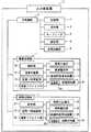
(A−1−2)入出金処理機能について
図3は、主制御部8の入出金処理機能を説明する機能ブロック図である。(A-1-2) Deposit / withdrawal processing function FIG. 3 is a functional block diagram for explaining the deposit / withdrawal processing function of the
図3において、入出金処理機能100は、パターン出金登録部101、出金処理部103、入金処理部104、集計処理部105、訂正処理部106、パターン出金記憶部107、シフト記憶部108、入出金履歴記憶部109を少なくとも有して構成される。 In FIG. 3, the deposit /
パターン出金登録部101は、複数の釣銭出金のパターン出金の設定情報をパターン出金記憶部107に登録するものである。ここで、パターン出金とは、予め設定された、出金に係る金種及び各金種の枚数を出金することをいう。 The pattern
パターン出金記憶部107は、パターン出金登録部101により登録処理された複数のパターン出金の設定情報を記憶するものである。 The pattern
図4は、パターン出金記憶部107の構成を示す構成図である。図4に示すように、パターン出金記憶部107は、出金パターン識別情報と、指定された金種及び各金種の枚数とを対応づけた情報を登録情報として記憶する。また、パターン出金記憶部107は、複数のパターン出金の設定情報を登録することができる。 FIG. 4 is a configuration diagram showing the configuration of the pattern
出金処理部103は、レジスタ担当者又は管理者の操作を受けて、釣銭出金処理を行なうものである。出金処理部103は、レジスタ担当者等の操作により、レジスタ識別情報、レジスタカードの識別情報、当該レジスタに割り当てられたシフト識別情報の選択入力を受ける。 The
そして、出金処理部103は、シフト記憶部108を参照して、入力されたレジスタ識別情報について、入力されたシフト識別情報に対応するパターン出金識別情報を検索し、検索されたパターン出金識別情報に対応する金種及び金種枚数を出金するものである。これにより、レジスタ毎に、選択されたシフトに対応付けられたパターン出金を行うことができる。 Then, the
また、出金処理部103は、レジスタ識別情報、レジスタカードの識別情報、シフト識別情報、レジスタ担当者識別情報、パターン出金金額を対応付けて、入出金履歴記憶部109に記憶する。これにより、シフトとレジスタカードとを対応付けて管理することができるので、1枚のレジスタカードでシフトのパターン出金を管理することができる。 Also, the
ここで、後述するように、この実施形態では、同一のレジスタカードについて、パターン出金がなされてから最終入金が行なわれるまでを1つのシフトとし、これを集計単位とする。 Here, as will be described later, in this embodiment, for the same register card, a period from when the pattern is dispensed to when the final deposit is made is defined as one shift, and this is set as a total unit.
従って、同一のレジスタカードについて、パターン出金がなされた後、最終入金がなされていない状態で、別のパターン出金の要求があっても、出金処理部103は取引を行なわない。つまり、この場合、出金処理部103は出金しない。これにより、レジスタ担当者がレジスタカードを間違えて出金処理を行なってしまうことを防止できる。 Therefore, even if there is a request for another pattern withdrawal in a state where the final deposit is not made after the pattern withdrawal is made for the same register card, the
なお、出金処理部103は、追加的に釣銭を出金する追加出金を行なうことができる。この場合、同一のレジスタカードについて、パターン出金がなされた後に最終入金がなされていない状態に、出金処理部103は追加出金を行なうことができる。追加出金の場合、出金処理部103は、金種及び枚数の入力を受け付け、その入力された金種及び枚数を出金する。 Note that the
入金処理部104は、レジスタ担当者又は管理者の操作を受けて、入金処理を行なうものである。入金処理部104は、レジスタ識別情報、レジスタカードの識別情報、レジスタ担当者識別情報、及び紙幣処理機2による入金された金種及び枚数が入力され、レジスタ識別情報、レジスタカードの識別情報、シフト識別情報、レジスタ担当者識別情報、入金金額を対応付けて入出金履歴記憶部109に記憶するものである。 The
ここで、入金処理部104が行なう入金には、少なくとも、最終入金と途中入金とがある。最終入金とは、原則的には、レジスタ担当者の勤務が終了した後に行われる最終的な売上入金である。途中入金とは、レジスタ担当者の勤務が終了する前に行う入金をいう。途中入金は、例えば、防犯の観点から、レジスタに収納される現金を定期的に回収して入金する場合に用いられる。入金処理部104は、最終入金と途中入金とを区別して入出金履歴記憶部109に記憶する。 Here, the deposit performed by the
集計処理部105は、入出金履歴記憶部109に記憶されている入出金履歴を参照して、レジスタ毎に設定されたシフトを集計単位として集計処理を行なうものである。つまり、集計処理部105は、あるレジスタについては、当該レジスタに用いたレジスタカードについて、パターン出金がなされてから最終入金がなされるまでを1つの集計単位として集計する。これは、「パターン出金から最終入金まで」が1シフトに相当するので、「パターン出金から最終入金まで」の集計が当該シフトの集計となる。 The
ここで、1集計単位とする「パターン出金から最終入金まで」の組の作成は、例えば、入出金履歴記憶部109における各取引の日時情報を用いて、今回の最終入金の取引日時情報の直前に行なわれたパターン出金を検索し、このパターン出金と最終入金とを1つの組とする。 Here, the creation of a set “from pattern withdrawal to final deposit” as one aggregation unit is performed using, for example, the date / time information of each transaction in the deposit / withdrawal
また、集計処理部105は、入出金履歴記憶部109に記憶されている入出金履歴を参照して、レジスタ識別情報毎、レジスタ担当者識別情報毎に集計するようにしてもよい。 Further, the totaling
訂正処理部106は、レジスタ担当者が出金処理及び又は入金処理を誤って操作した場合に、正しい出金処理及び又は入金処理に訂正するものである。訂正処理部106による訂正処理については、動作の項で詳細に説明する。 The
なお、図16は、主制御部8の入出金処理機能の変形実施形態を説明する機能ブロック図である。図16は、図3に例示した入出金処理機能の各構成要素に、シフト設定部102を追加したものである。FIG. 16 is a functional block diagram illustrating a modified embodiment of the deposit / withdrawal processing function of the
シフト設定部102は、管理者の操作を受けて、レジスタ担当者のシフトに対して、指定されたパターン出金識別情報を対応付けてシフト記憶部108に記憶させるものである。シフトは各レジスタに割り当てられるのが一般的であるため、各レジスタのそれぞれのシフト毎にパターン出金が割り当てられる。 In response to the operation of the administrator, the
具体的には、シフト設定部102は、レジスタ毎に、シフトの時間帯が入力され、その時間帯のシフトに対してシフト識別情報を付与する。そして、シフト設定部102は、レジスタ毎に、シフト識別情報と指定されたパターン出金識別情報とを対応付けてシフト記憶部108に記憶する。 Specifically, the
このように、予めシフト設定部102によりシフトを設定しておくことで、レジスタ担当者は、釣銭出金を行なうときに、「自身のシフト」のみを選択するだけでよい。その結果、レジスタ担当者によるパターン出金の選択間違いを回避できる。 As described above, by setting the shift by the
(A−2)実施形態の動作
次に、実施形態に係る入出金装置10における入出金処理の動作について図面を参照しながら詳細に説明する。(A-2) Operation | movement of embodiment Next, operation | movement of the deposit or withdrawal process in the deposit or
(A−2−1)シフト設定処理について
図5は、レジスタ識別情報「1」のレジスタのシフトを示す図である。図5において、「9:00〜12:00」の時間帯を「シフト1」とし、「11:30〜14:00」の時間帯を「シフト2」とし、「13:30〜18:00」の時間帯を「シフト3」とする。(A-2-1) Shift setting process FIG. 5 is a diagram showing a shift of the register of the register identification information “1”. In FIG. 5, the time zone “9:00 to 12:00” is “
管理者は、管理者カードをカードリーダ5で読み取らせ、操作部4によりシフト設定処理の選択ボタンを選択する。これにより、シフト設定処理が開始する。 The administrator causes the
次に、管理者は、操作部4を操作してレジスタ識別情報を入力する。例えば、図5のシフト設定を行なう場合、管理者は、レジスタ識別情報「1」を入力する。 Next, the administrator operates the
そして、管理者が図5の「シフト1」について設定する場合、管理者は時間帯「9:00〜12:00」を入力する。入出金装置10において、シフト設定部102は、入力された時間帯「9:00〜12:00」に対してシフト識別情報:シフト1」を割り当てる。 When the administrator sets “
次に、管理者は、操作部4を操作して、「シフト1」に対応付けるパターン出金を選択する。例えば、「シフト1」に対して、図4の「パターン1」が選択されると、シフト設定部102は、「シフト1」に対して、選択された「パターン1」を対応付けてシフト記憶部108に記憶する。 Next, the administrator operates the
このような処理が、他のシフトについてもなされる。また、他のレジスタの各シフトについてもなされる。 Such processing is performed for other shifts. It is also made for each shift of other registers.
図6は、シフト記憶部108に記憶されるシフト設定情報の構成を例示する構成図である。図6に示すように、レジスタ(レジスタ識別情報)毎に、時間帯、シフト識別情報、パターン出金識別情報が対応付けて管理される。例えば、「レジスタ識別情報:1」について、「9:00〜12:00」は「シフト識別情報:シフト1」が付与され、「シフト1」には「パターン出金識別情報:パターン1」が対応付けて記憶される。 FIG. 6 is a configuration diagram illustrating a configuration of shift setting information stored in the
なお、ここでは、管理者が、あらかじめ、シフトに対してパターン出金を対応付ける場合を例示した。しかし、レジスタカードについて、パターン出金及び最終入金を対応づけることができればよいので、管理者が上記のシフト設定を行わないようにしてもよい。その場合、レジスタ担当者が、レジスタカードを用いて出金処理を行なう際に、パターン出金を選択することで、レジスタカードとパターン出金とを対応付けることができる。 Here, the case where the administrator associates the pattern withdrawal with the shift in advance is exemplified. However, since it is sufficient that the pattern withdrawal and the final deposit can be associated with each other for the register card, the manager may not perform the shift setting. In that case, when the register person performs the withdrawal process using the register card, the register card can be associated with the pattern withdrawal by selecting the pattern withdrawal.
(A−2−2)出金処理
次に、この実施形態に係る入出金装置10における出金処理について図面を参照しながら詳細に説明する。(A-2-2) Withdrawal process Next, the withdrawal process in the depositing / withdrawing
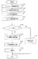
図7は、実施形態に係る入出金装置10における出金処理の動作を示すフローチャートである。 FIG. 7 is a flowchart showing the operation of the withdrawal process in the deposit /
図7において、レジスタ担当者は、レジスタカードをカードリーダ5に読み取らせ、操作部4を操作して、レジスタ担当者識別情報を入力し、釣銭出金の選択ボタンを選択する。これにより、入出金装置10において、出金処理部103は、レジスタカード識別情報及びレジスタ担当者識別情報を取得して、釣銭出金処理を開始する(S101、S102)。 In FIG. 7, the register person makes the
次に、レジスタ担当者は、操作部4を操作してレジスタ識別情報を入力する。これにより、出金処理部103は、レジスタ識別情報を取得する(S103)。 Next, the register person operates the
なお、レジスタカードがレジスタに対応することが予め設定されている場合(例えば、レジスタカードから読み取った情報にレジスタ識別情報が含まれる等の場合)には、レジスタ識別情報の入力を省略するようにしてもよい。 If it is preset that the register card corresponds to the register (for example, the register identification information is included in the information read from the register card), the input of the register identification information should be omitted. May be.
また、管理者は、管理者カードを用いて、パターン出金や追加出金等の出金処理を行なうこともできる。その場合には、レジスタ識別情報及びシフトの入力が必要となる。 In addition, the manager can perform a withdrawal process such as pattern withdrawal or additional withdrawal using the manager card. In that case, it is necessary to input register identification information and shift.
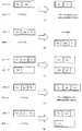
図8及び図9は、釣銭出金に係る表示画面例を示す画面図である。図8(A)に示すように画面には、レジスタ選択ボタン501が表示される。レジスタ担当者は、図8(A)の画面において、担当するレジスタのレジスタ選択ボタン501を選択し、確認ボタン502を選択する。 8 and 9 are screen views showing examples of display screens related to change dispensing. As shown in FIG. 8A, a
続いて、出金処理部103は、パターン出金による釣銭出金を行なうために、パターン出金識別情報を取得する(S105)。 Subsequently, the
ここで、(A−2−1)で説明したシフト設定が予めなされている場合、図8(B)に例示する表示画面において、レジスタ担当者は、担当するシフトのシフト選択ボタン503を選択し、確認ボタン502を押下する。そして、出金処理部103は、図6に例示するシフト設定情報を参照して、選択されたシフト識別情報に対応するパターン出金識別情報を取得することができる。 Here, when the shift setting described in (A-2-1) has been made in advance, the register person selects the
また別の方法として、(A−2−1)で説明したシフト設定が予めなされていない場合、図9(A)に例示する表示画面において、レジスタ担当者が、「パターン出金」を示す出金種類選択ボタン504を選択する。そうすると、図9(B)に例示する表示画面が表示される。レジスタ担当者は、図9(B)において、パターン出金のタイプが異なるパターン出金選択ボタン505を選択すると、その選択されたパターン出金の金種枚数及び合計金額が表示される。これを見て、レジスタ担当者は、パターン出金のタイプを確認できる。そして、レジスタ担当者は、当該シフトに割り当てられているパターン出金のパターン出金選択ボタン505を選択し、確認ボタン502を押下する。これにより、出金処理部103は、パターン出金識別情報を取得することができる。 As another method, when the shift setting described in (A-2-1) is not performed in advance, the register person in charge displays “pattern withdrawal” on the display screen illustrated in FIG. The money
S106では、出金処理部103が、同一のレジスタカードを用いてパターン出金が既になされているか否かを確認し(S106)、パターン出金がなされていない場合、出金処理部103は処理をS107に移行し、既にパターン出金がなされている場合、出金処理部103は処理をS110に移行する。 In S106, the
S107において、出金処理部103は、硬貨処理機1及び紙幣処理機2に対して、パターン出金識別情報に対応する金種及び枚数を出金するようにし指示し、硬貨処理機1及び紙幣処理機2が指示された金種及び枚数を出金する(S107)。 In S107, the
そして、出金処理部103は、レジスタ識別情報、レジスタカード識別情報、レジスタ担当者識別情報、パターン出金である旨の区分、出金金額を対応付けて、入出金履歴記憶部109に記憶し(S108)、伝票記録部6が釣銭出金に係る伝票を発行する(S109)。 Then, the
図10は、入出金履歴記憶部109における入出金履歴を説明する説明図である。図10に示すように、出金処理部103は、例えば、「通番:1」に、「レジスタ識別情報:1」、「レジスタカード識別情報:A」、「レジスタ担当者識別情報:1111」について、「区分:パターン出金」を付与し、当該パターン出金の出金金額及び金種枚数を対応付けて入出金履歴に残す。 FIG. 10 is an explanatory diagram for explaining the deposit / withdrawal history in the deposit / withdrawal
一方、S106において、既にパターン出金がなされている場合、出金処理部103は、パターン出金を行なわず、エラーである旨を出力して、処理を終了する(S110)。 On the other hand, if the pattern withdrawal has already been made in S106, the
(A−2−3)最終入金処理
次に、この実施形態に係る入出金装置10における最終入金処理について図面を参照しながら詳細に説明する。(A-2-3) Final Deposit Processing Next, the final deposit processing in the deposit /
図11は、実施形態に係る入出金装置10における最終入金処理の動作を示すフローチャートである。 FIG. 11 is a flowchart showing the operation of the final deposit process in the deposit /
図11において、レジスタ担当者は、レジスタカードをカードリーダ5に読み取らせ、操作部4を操作して、レジスタ担当者識別情報を入力し、最終入金の選択ボタンを選択する。これにより、入出金装置10において、入金処理部104は、レジスタカード識別情報及びレジスタ担当者識別情報を取得して、最終入金処理を開始する(S201、S202)。 In FIG. 11, the register person makes the
次に、レジスタ担当者は、操作部4を操作してレジスタ識別情報を入力する。これにより、入金処理部104は、レジスタ識別情報を取得する(S203)。 Next, the register person operates the
続いて、レジスタ担当者によって投入された現金を、硬貨処理機1及び紙幣処理機2が受け入れ、硬貨処理機1及び紙幣処理機2が現金を計数する(S204)。 Subsequently, the
ここで、入金処理を行なう際、硬貨処理機1及び紙幣処理機2による現金計数だけでなく、レジスタ担当者の手入力による入金処理を行なうようにしてもよい。これは、例えば、商品券や、クレジットカード、ギフトカード等による売上や、また汚損金等もあるため、硬貨処理機1及び紙幣処理機2が計数できない場合もあるからである。このような場合には、レジスタ担当者が手入力により入金処理を行ない、入金金額等を確定する。 Here, when performing a deposit process, you may make it perform the deposit process not only by the cash counting by the
そして、入金処理部104は、レジスタ識別情報、レジスタカード識別情報、レジスタ担当者識別情報、最終入金である旨の区分、入金金額を対応付けて、入出金履歴記憶部109に記憶し(S205)、伝票記録部6が最終入金に係る伝票を発行する(S206)。 Then, the
図10に示すように、入金処理部104は、例えば、「通番:2」に、「レジスタ識別情報:1」、「レジスタカード識別情報:A」、「レジスタ担当者識別情報:1111」について、「区分:最終入金」を付与し、当該最終入金として計数された入金金額及び金種枚数を対応付けて入出金履歴に残す。 As shown in FIG. 10, for example, the
(A−2−4)集計処理
次に、実施形態に係る入出金装置10における集計処理の動作について図面を参照しながら説明する。(A-2-4) Aggregation Process Next, the operation of the aggregation process in the deposit /
図12は、集計処理部105による集計単位を説明する説明図である。図13は、レジスタ識別情報「1」のシフト及び集計を説明する説明図である。 FIG. 12 is an explanatory diagram for explaining a counting unit by the
図13では、レジスタ識別情報「1」のレジスタについて、複数のレジスタ担当者が、2枚のレジスタカード「カードA」と「カードB」を用いて操作する場合を示す。 FIG. 13 shows a case where a plurality of register managers operate the register having the register identification information “1” using two register cards “card A” and “card B”.
また、シフト1はレジスタ識別情報「1111」の担当者が担当し、シフト2はレジスタ識別情報「2222」の担当者が担当し、シフト3は、レジスタ識別情報「3333」と「1111」の2人の担当者が担当するものとする。 In addition, the person in charge of register identification information “1111” is in charge of
さらに、シフト1及びシフト3では、レジスタ担当者がレジスタカード「カードA」を用いており、シフト2では、レジスタ担当者がレジスタカード「カード」Bを用いているものとする。 Further, in
上記のような場合、図12に示すように、集計処理部105は、入出金履歴記憶部109に記憶される入出金履歴に基づいて、同一レジスタカードについて、パターン出金がなされてから最終入金がなされるまでを1つの集計単位とする。 In such a case, as shown in FIG. 12, the
すなわち、集計処理部105は、入出金履歴記憶部109を参照して、レジスタカード識別情報に対応する入出金履歴を検索して、同一のレジスタ識別情報において、パターン出金とその後になされた最終入金とを組にし、これを集計単位として集計する。 That is, the
例えば、図12において、集計処理部105は、レジスタカード識別情報「カードA」について、レジスタ担当者識別情報「1111」による「パターン出金」を読み出し、同一のレジスタカード識別情報「カードA」であって、当該パターン出金直後の「最終入金」を読み出す。そして、この「パターン出金から最終入金まで」がシフト1についての集計となる。 For example, in FIG. 12, for the register card identification information “card A”, the
また、「シフト2」についても同様に、レジスタカード識別情報「カードB」について、レジスタ担当者識別情報「2222」による「パターン出金」と、当該パターン出金直後の「最終入金」とを読み出し、これをシフト2の集計とする。 Similarly, for “
ここで、シフト3では「カードA」が利用されており、利用カードはシフト1のときと同じであるため、集計処理部105がシフトを誤って括ってしまうことが問題となる。しかし、この実施形態では、上記のような誤ったシフトの括りを防止するために、出金処理部103が、パターン出金済み後の再度のパターン出金を選択できないようにしている(図7のS106及びS110参照)。その結果、同一のレジスタカードにおいて、パターン出金後に、別のパターン出金がなされることはないので、集計処理部105は、「パターン出金から最終入金まで」を1つの集計単位として確実に括ることができる。 Here, since “card A” is used in shift 3, and the card used is the same as that in
また、レジスタ担当者が最終入金を忘れてしまうこともあり、レジスタ担当者又は管理者が遅れて最終入金を行なう場合もある。しかし、この実施形態では、図13に示すように、同一のレジスタカード「カードA」について、「シフト1」が終わってから、「シフト3」についての「パターン出金」がなされるまでの間を、「シフト1」の集計最大範囲とする。つまり、「パターン出金から最終入金まで」が1つの集計単位であるから、次のシフトの「パターン出金」がなされるまで、「最終入金」が可能となる。 In addition, the register person may forget the final deposit, and the register person or the manager may make the final deposit after a delay. However, in this embodiment, as shown in FIG. 13, for the same register card “card A”, after “
また、図12において、シフト3では、レジスタ担当者識別情報「3333」が「カードA」を用いてパターン出金を行い、レジスタ担当者識別情報「1111」が「カードA」を用いて最終入金を行なっている。つまり、釣銭出金と最終入金の行為主体がそれぞれ異なる。 In FIG. 12, in shift 3, the register person identification information “3333” uses “card A” to make a pattern withdrawal, and the register person identification information “1111” uses “card A” as the final deposit. Is doing. In other words, the actors for change withdrawal and final deposit are different.
この場合でも、集計処理部105は、同一のレジスタカード識別情報について「パターン出金から最終入金まで」を集計単位とするので、問題なく集計処理を行なうことができる。なお、この場合、個人集計については、レジスタ担当者識別情報「3333」又は「1111」のいずれかの売上計上であるとしてもよい。この実施形態では、最終入金を行なったレジスタ担当者識別情報「1111」の売上計上とする。 Even in this case, the
なお、図12に示すように、集計処理部105は、レジスタ識別情報毎、レジスタ担当者識別情報毎に集計を行なうこともできるので、レジスタ毎、レジスタ担当者毎の売上集計もできる。なお、図12において、点線で括ったものの集計が、レジスタ識別情報「1」の集計である。 As shown in FIG. 12, the
集計処理部105は、上記のようにして集計した集計結果を入出金履歴記憶部109に記憶する。 The
(A−2−5)訂正処理
次に、この実施形態の入出金装置10における訂正処理の動作について図面を参照しながら説明する。(A-2-5) Correction Process Next, the operation of the correction process in the deposit /
訂正処理部106は、レジスタ担当者又は管理者による操作を受けて、レジスタカード識別情報毎の集計や、レジスタ識別情報毎の集計を訂正するものである。 The
訂正処理部106は、レジスタ担当者が使用するレジスタカードを間違えて、パターン出金、追加出金、最終入金等を行なった場合に、訂正処理を行なう。 The
上述したように、出金処理及び入金処理がなされると、入出金装置10は、通番を付して、出金処理及び入金処理を行なう。このとき、入出金装置10は、出金処理及び入金処理に係る通番を記載した伝票を発行する。As described above, when the withdrawal process and the deposit process are performed, the deposit /
訂正処理部106は、レジスタ担当者又は管理者から、出金処理及び入金処理に係る通番の入力を受け付け、入力された通番に対応する出金処理及び入金処理について訂正を行なう。 The
また、訂正処理部106は、訂正回数を管理するようにしてもよい。これは、管理者が訂正を管理するためである。 The
さらに、この実施形態はシフトという概念で集計処理を行なうため、訂正処理部106は、従来の訂正処理と大きく異なる。例えば出金処理について訂正する場合、従来は、出金取引の履歴について、誤ったカード識別情報を正しいカード識別情報に訂正するということを行なっている。また、訂正対象は、例えば出金処理、入金処理等のように、それぞれの個別の取引が対象となる。 Furthermore, since this embodiment performs the aggregation process based on the concept of shift, the
しかし、この実施形態では、シフトという集計単位で集計処理を行なうので、単に「パターン出金」の履歴及びそのパターン出金後の取引(例えば、追加出金、最終入金等も含む取引)の履歴を入れ替えるだけでなく、訂正処理部106は1シフトとして括られる取引を関連付けて訂正する。 However, in this embodiment, since the aggregation process is performed in the aggregation unit called shift, the history of “pattern withdrawal” and the history of transactions after the pattern withdrawal (for example, transactions including additional withdrawal, final deposit, etc.) In addition, the
図14及び図15は、訂正処理部106による訂正処理を説明する説明図である。図14及び図15では、「カードA」と「カードB」との間の訂正処理を例示して説明する。 14 and 15 are explanatory diagrams for explaining the correction processing by the
なお、図14及び図15において、例えば、「Pe1」等は「パターン出金」を示し、「Ae1」等は「追加出金」を示し、「Fr1」等は「最終入金」を示す。 14 and 15, for example, “Pe1” or the like indicates “pattern withdrawal”, “Ae1” or the like indicates “additional withdrawal”, and “Fr1” or the like indicates “final deposit”.
図14(A)は、「カードA」及び「カードB」のそれぞれのパターン出金を、入れ替える場合である。 FIG. 14A shows a case where the pattern withdrawals of “card A” and “card B” are exchanged.
この場合、訂正処理部106は、「パターン出金:Pe1」の伝票の通番と、「パターン出金:Pe2」の伝票の通番との入力を受け付ける。そして、訂正処理部106は、入出金履歴記憶部109を参照して、入力された2つの通番に基づいて、対応する2つの出金履歴を読み出す。そして、訂正処理部106は、パターン出金識別情報や出金金額及び金種枚数を相互に入れ替える訂正を行なう。 In this case, the
また、訂正処理部106は、レジスタカード識別情報「カードA」及び「カードB」に今回の訂正回数をカウントする。 Further, the
図14(B)は、パターン出金済みの「カードA」のパターン出金を、まだパターン出金がなされていない「カードB」に付け替える場合である。 FIG. 14B shows a case where the pattern withdrawal of “card A” that has been subjected to pattern withdrawal is replaced with “card B” that has not yet been subject to pattern withdrawal.
この場合、訂正処理部106は、「パターン出金:Pe2」の伝票の通番の入力を受け付け、入出金履歴記憶部109を参照して、入力された通番に基づいて、対応する出金履歴を読み出す。そして、訂正処理部106は、レジスタカード識別情報を「カードA」から「カードB」に訂正する。これにより、「カードA」のシフトは削除され、シフトがなかった「カードB」についてパターン出金が付与される。 In this case, the
また、訂正処理部106は、レジスタカード識別情報「カードB」に今回の訂正回数をカウントする。 Further, the
図14(C)は、追加出金済みの「カードA」のパターン出金及び追加出金を、まだパターン出金していない「カードB」に付け替える場合である。 FIG. 14C shows a case in which the pattern withdrawal and additional withdrawal of “card A” that has already undergone additional withdrawal are replaced with “card B” that has not yet been subject to pattern withdrawal.
ここで、追加出金は、パターン出金がなされていることが前提で追加的に出金されるものである。また、追加出金は、1シフトに関連する取引である。従って、訂正処理部106は追加出金の取引だけの付け替えでなく、パターン出金と関連性を持たせた付け替えを行なう。つまり、訂正処理部106は追加出金のみの付け替えはできない。 Here, the additional withdrawal is an additional withdrawal on the assumption that the pattern withdrawal has been made. Additional withdrawals are transactions related to one shift. Accordingly, the
この場合、訂正処理部106は、パターン出金との関連性を持たせるために、「パターン出金:Pe2」の伝票の通番の入力を受け付ける。そして、訂正処理部106は、入出金履歴記憶部109を参照して、入力された通番に基づいて、対応する出金履歴を読み出す。そして、訂正処理部106は、パターン出金及び追加出金の両方の出金履歴を検索し、両方の出金履歴についてレジスタカード識別情報を「カードA」から「カードB」に訂正する。これにより、「カードA」のシフトは削除され、シフトがなかった「カードB」についてパターン出金及び追加出金が付与される。 In this case, the
また、訂正処理部106は、レジスタカード識別情報「カードB」に今回の訂正回数をカウントする。 Further, the
図14(D)は、追加出金済みの「カードA」の追加出金を、パターン出金済みの「カードB」に付け替える場合である。つまり、本来のパターン出金に関連付けるべき追加出金を、間違えたパターン出金に関連付けてしまった場合である。 FIG. 14D shows a case where the additional withdrawal of “card A” that has already been withdrawn is replaced with “card B” that has undergone pattern withdrawal. That is, it is a case where the additional withdrawal that should be associated with the original pattern withdrawal is associated with the wrong pattern withdrawal.
この場合、訂正処理部106は、「追加出金:Ae2」の通番の入力を受け付け、入出金履歴記憶部109を参照して、入力された通番に基づいて、対応する出金履歴を読み出す。そして、訂正処理部106は、追加出金の出金履歴について、レジスタカード識別情報を「カードA」から「カードB」に訂正する。これにより、「追加出金:Ae2」のみが「カードB」に付加され、「カードA」にあった「追加出金:Ae2」が削除される。 In this case, the
また、訂正処理部106は、レジスタカード識別情報「カードA」及び「カードB」に今回の訂正回数をカウントする。 Further, the
図15(A)は、追加出金済みの「カードA」の追加出金を、パターン出金されていない「カードB」に付け替える場合である。 FIG. 15A shows a case where the additional withdrawal of “card A” that has already been withdrawn is replaced with “card B” that has not been subject to pattern withdrawal.
この場合、訂正処理部106は、訂正しない。これは、追加出金は、パターン出金がなされていることが前提で追加的に出金されるものである。従って、訂正処理部106は、パターン出金がなされていない「カードB」への付け替えを行わない。 In this case, the
このとき、訂正処理部106は、入出金装置10が有する報知手段(例えば、アラーム手段等)に対して警告を報知するよう指示するようにしてもよい。 At this time, the
図15(B)は、最終入力済みの「カードA」のパターン出金を、まだパターン出金していない「カードB」に付け替える場合である。訂正処理部106はパターン出金から最終入金までの全ての取引を付け替える。 FIG. 15B shows a case where the pattern withdrawal of “card A” that has been finally input is replaced with “card B” that has not yet been subjected to pattern withdrawal. The
この場合、訂正処理部106は、シフトのパターン出金を特定するために、「パターン出金:Pe2」の伝票の通番の入力を受け付ける。そして、訂正処理部106は、入出金履歴記憶部109を参照して、そのパターン出金取引から最終入金取引までの全ての取引を特定するために、パターン出金から最終入力までの出金処理及び入金処理の履歴を読み出す。そして、訂正処理部106は、読み出した出金処理及び入金処理の全ての履歴について、レジスタカード識別情報を「カードA」から「カードB」に訂正する。これにより、「カードA」のシフトは削除され、シフトがなかった「カードB」についてパターン出金、追加出金及び追加出金が付与される。 In this case, the
また、訂正処理部106は、レジスタカード識別情報「カードB」に今回の訂正回数をカウントする。 Further, the
図15(C)は、最終入金済みの「カードA」の最終入金のみを、パターン出金済みの「カードB」に付け替える場合である。 FIG. 15C shows a case where only the final deposit of “card A” that has been final deposited is replaced with “card B” that has undergone pattern withdrawal.
この場合、訂正処理部106は、「最終入金:Fr2」の伝票の通番の入力を受け付け、入出金履歴記憶部109を参照して、対応する最終入力の入金処理の履歴を読み出す。そして、訂正処理部106は、読み出した入金処理の履歴について、レジスタカード識別情報を「カードA」から「カードB」に訂正する。これにより、「カードA」の最終入金は削除され、「カードB」に最終入金が付与される。 In this case, the
また、訂正処理部106は、レジスタカード識別情報「カードB」に今回の訂正回数をカウントする。 Further, the
図15(D)は、最終入金済みの「カードA」の最終入金のみを、まだパターン出金されていない「カードB」に付け替える場合である。 FIG. 15D shows a case where only the final deposit of “card A” that has been final deposited is replaced with “card B” that has not yet been subjected to pattern withdrawal.
この場合、訂正処理部106は、訂正しない。これは、最終入金は、シフトを形成するため、パターン出金がなされていることが前提であり、パターン出金されていない「カードB」への付け替えを行わないようにするためである。 In this case, the
このとき、訂正処理部106は、入出金装置10が有する報知手段(例えば、アラーム手段等)に対して警告を報知するよう指示するようにしてもよい。 At this time, the
図15(E)は、図15(D)の例外である。図15(E)は、最終入金済みの「カードA」の最終入金のみを、出金不可制限されているレジスタのレジスタカード「カードB」に付け替える場合である。 FIG. 15E is an exception to FIG. FIG. 15E shows a case where only the final deposit of “card A” that has been final deposited is replaced with the register card “card B” of a register that is restricted to withdraw money.
本来、最終入金は、パターン出金されているレジスタカードにのみ付与される。しかし、カードの種類によって、レジスタの売上だけを集計する目的の出金負荷制限されたレジスタのレジスタカードがある。 Originally, the final deposit is given only to the register card on which the pattern is withdrawn. However, depending on the type of card, there is a register card of a register whose withdrawal load is limited for the purpose of counting only the sales of the register.
その場合、訂正処理部106は、「最終入金:Fr1」の伝票の通番の入力を受け付け、入出金履歴記憶部109を参照して、対応する最終入力の入金処理の履歴を読み出す。そして、訂正処理部106は、読み出した入金処理の履歴について、レジスタカード識別情報を「カードA」から「カードB」に訂正する。これにより、「カードA」の最終入金は削除され、「カードB」に最終入金が付与される。 In that case, the
また、訂正処理部106は、レジスタカード識別情報「カードB」に今回の訂正回数をカウントする。 Further, the
(A−3)実施形態の効果
以上のように、この実施形態によれば、レジスタへの出金又はレジスタからの入金に用いられるレジスタカード毎に、パターン出金から最終入金までを1集計単位として集計処理ができる。この集計単位は、レジスタ担当者のシフトに相当する。従って、この実施形態によれば、シフト毎に、売上集計を行なうことができる。(A-3) Effect of Embodiment As described above, according to this embodiment, one total unit from pattern withdrawal to final deposit is provided for each register card used for withdrawal to a register or deposit from a register. Can be tabulated. This aggregation unit corresponds to the shift of the register person. Therefore, according to this embodiment, sales can be counted for each shift.
また、この実施形態によれば、レジスタカード識別情報に、レジスタ識別情報、レジスタ担当者識別情報を紐付して入出金履歴を記憶する。そのため、レジスタ識別情報でソートすればレジスタ毎の売上集計を求めることができ、又、レジスタ担当者識別情報でソートすればレジスタ担当者毎の売上集計を求めることができる。 According to this embodiment, the register card identification information is associated with the register identification information and the register person identification information, and the deposit / withdrawal history is stored. Therefore, it is possible to obtain the sales total for each register by sorting by the register identification information, and it is possible to obtain the sales total for each register person by sorting by the register person identification information.
(B)他の実施形態
(B−1)上述した実施形態における入出金装置は、1店舗に設けられるレジスタへの出金処理及びレジスタからの入金処理を行なうものに限定されるものではなく、例えば、ショッピングセンタ等のように複数のショップからなる大規模店舗において、各ショップを統括的に管理するものにも適用することができる。(B) Other Embodiments (B-1) The deposit / withdrawal apparatus in the above-described embodiment is not limited to the one that performs the withdrawal process to the register provided in one store and the deposit process from the register, For example, the present invention can also be applied to a large-scale store composed of a plurality of shops such as a shopping center that manages each shop in an integrated manner.
(B−2)上述した実施形態では、レジスタの出金又は入金に用いられる媒体として、レジスタカードを適用する場合を例示した。しかし、シフトに応じてレジスタを利用する際に用いられるものであれば、カードに限定されるものではない。(B-2) In the above-described embodiment, the case where the register card is applied as the medium used for the withdrawal or deposit of the register is illustrated. However, the present invention is not limited to a card as long as it is used when a register is used according to a shift.
10…入出金装置、1…硬貨処理機、2…紙幣処理機、3…表示部、4…操作部、5…カードリーダ、6…伝票記録部、7…記憶部、8…主制御部、
101…パターン出金登録部、102…シフト設定部、103…出金処理部、104…入金処理部、105…集計処理部、106…訂正処理部、107…パターン出金記憶部、108…シフト記録部、109…入出金履歴記憶部。DESCRIPTION OF
DESCRIPTION OF
Claims (3)
Translated fromJapanese少なくとも、レジスタへの出金又はレジスタからの入金に用いられる媒体の媒体識別情報に、出金情報及び又は入金情報を対応付けて記憶する入出金情報記憶手段と、
上記複数の出金パターンの中から選択された出金パターンで出金処理を行なうものであって、上記選択された出金パターンで出金した出金情報を、取得した上記媒体識別情報に対応付けて上記入出金情報記憶手段に記憶させる出金処理手段と、
レジスタからの入金情報を取得し、上記入金情報を、取得した上記媒体識別情報に対応付けて上記入出金記憶手段に記憶させる入金処理手段と、
上記入出金情報記憶手段を参照して、上記媒体識別情報毎に、上記出金パターンで出金するパターン出金がされてから最終入金がされるまでを1集計単位として集計処理を行なう集計処理手段と、
上記集計処理手段により形成される上記媒体識別情報の集計単位毎に、出金情報及び又は入金情報の内容の訂正要求を受け付け、要求された内容で訂正を行なう訂正処理手段と
を備えことを特徴とする入出金装置。A withdrawal pattern storage means for storing a plurality of withdrawal patterns for dispensing a predetermined denomination and number;
At least deposit / withdrawal information storage means for storing the withdrawal information and / or the deposit information in association with the medium identification information of the medium used for withdrawal to the register or deposit from the register;
Withdrawing with a withdrawal pattern selected from the plurality of withdrawal patterns, withdrawing information withdrawn with the selected withdrawal pattern corresponding to the acquired medium identification information Withdrawing processing means to be stored in the deposit / withdrawal information storage means,
Deposit processing means for acquiring deposit information from a register, and storing the deposit information in the deposit / withdrawal storage means in association with the acquired medium identification information;
Referring to the deposit / withdrawal information storage means, a tabulation process is performed for each medium identification information, with a counting unit from a pattern withdrawal with which the withdrawal pattern is dispensed until a final deposit is made. Processing means;
Correction processing means for accepting a request for correction of the contents of the withdrawal information and / or the deposit information and correcting the requested contents for each unit of counting of the medium identification information formed by the counting processing means. Deposit and withdrawal equipment.
少なくとも、レジスタへの出金又はレジスタからの入金に用いられる媒体の媒体識別情報に、出金情報及び又は入金情報を対応付けて記憶する入出金情報記憶手段と、
上記複数の出金パターンの中から選択された出金パターンで出金処理を行なうものであって、上記選択された出金パターンで出金した出金情報を、取得した上記媒体識別情報に対応付けて上記入出金情報記憶手段に記憶させる出金処理手段と、
レジスタからの入金情報を取得し、上記入金情報を、取得した上記媒体識別情報に対応付けて上記入出金記憶手段に記憶させる入金処理手段と、
上記入出金情報記憶手段を参照して、上記媒体識別情報毎に、上記出金パターンで出金するパターン出金がされてから最終入金がされるまでを1集計単位として集計処理を行なう集計処理手段と
を備え、
上記出金処理手段が、選択された出金パターンで出金処理を行なう際に、取得した上記媒体識別情報について、既にパターン出金がなされており、最終入金が完結していないとき、上記選択された出金パターンの出金処理を行なわない
ことを特徴とする入出金装置。A withdrawal pattern storage means for storing a plurality of withdrawal patterns for dispensing a predetermined denomination and number;
At least deposit / withdrawal information storage means for storing the withdrawal information and / or the deposit information in association with the medium identification information of the medium used for withdrawal to the register or deposit from the register;
Withdrawing with a withdrawal pattern selected from the plurality of withdrawal patterns, withdrawing information withdrawn with the selected withdrawal pattern corresponding to the acquired medium identification information Withdrawing processing means to be stored in the deposit / withdrawal information storage means,
Deposit processing means for acquiring deposit information from a register, and storing the deposit information in the deposit / withdrawal storage means in association with the acquired medium identification information;
Referring to the deposit / withdrawal information storage means, a tabulation process is performed for each medium identification information, with a counting unit from a pattern withdrawal with which the withdrawal pattern is dispensed until a final deposit is made. Processing means and
With
When the withdrawal processing means performs the withdrawal process with the selected withdrawal pattern, the selection is made when the pattern withdrawal has already been made for the acquired medium identification information and the final deposit has not been completed.dispenser module characterized in that not performed dispensing process dispensing patterns.
Priority Applications (1)
| Application Number | Priority Date | Filing Date | Title |
|---|---|---|---|
| JP2012027104AJP5807577B2 (en) | 2012-02-10 | 2012-02-10 | Deposit / withdrawal equipment |
Applications Claiming Priority (1)
| Application Number | Priority Date | Filing Date | Title |
|---|---|---|---|
| JP2012027104AJP5807577B2 (en) | 2012-02-10 | 2012-02-10 | Deposit / withdrawal equipment |
Publications (2)
| Publication Number | Publication Date |
|---|---|
| JP2013164714A JP2013164714A (en) | 2013-08-22 |
| JP5807577B2true JP5807577B2 (en) | 2015-11-10 |
Family
ID=49176030
Family Applications (1)
| Application Number | Title | Priority Date | Filing Date |
|---|---|---|---|
| JP2012027104AActiveJP5807577B2 (en) | 2012-02-10 | 2012-02-10 | Deposit / withdrawal equipment |
Country Status (1)
| Country | Link |
|---|---|
| JP (1) | JP5807577B2 (en) |
Families Citing this family (1)
| Publication number | Priority date | Publication date | Assignee | Title |
|---|---|---|---|---|
| JP7434946B2 (en)* | 2020-01-30 | 2024-02-21 | 沖電気工業株式会社 | information processing equipment |
Family Cites Families (2)
| Publication number | Priority date | Publication date | Assignee | Title |
|---|---|---|---|---|
| US7500568B2 (en)* | 2005-06-16 | 2009-03-10 | Traidis | Standalone device and method for managing, depositing and dispensing cash |
| JP5000320B2 (en)* | 2007-02-02 | 2012-08-15 | ローレル機械株式会社 | System for simultaneous processing of deposits and changes in sales proceeds |
- 2012
- 2012-02-10JPJP2012027104Apatent/JP5807577B2/enactiveActive
Also Published As
| Publication number | Publication date |
|---|---|
| JP2013164714A (en) | 2013-08-22 |
Similar Documents
| Publication | Publication Date | Title |
|---|---|---|
| CN101887605B (en) | Banknote processing device | |
| JP2010272024A (en) | Automatic transaction apparatus | |
| JP5309458B2 (en) | Cash processing equipment | |
| JP5087889B2 (en) | Cash processing equipment | |
| JP5012199B2 (en) | Cash processing equipment | |
| JP4894324B2 (en) | Cash processing equipment | |
| JP2014232446A (en) | Cash processor | |
| JP5994606B2 (en) | Cash processing apparatus and cash processing program | |
| JP5194413B2 (en) | Cash dispenser | |
| JP5200388B2 (en) | Cash processing equipment | |
| JP5807586B2 (en) | Deposit / withdrawal device, information processing device and cash processing system | |
| JP4946283B2 (en) | Cash processing equipment | |
| JP5464253B2 (en) | Cash dispenser | |
| JP5807577B2 (en) | Deposit / withdrawal equipment | |
| JP5115167B2 (en) | Cash processing equipment | |
| JP5200502B2 (en) | Cash processing equipment | |
| JP5012125B2 (en) | Cash processing equipment | |
| JP6007821B2 (en) | Cash processing equipment | |
| JP5293323B2 (en) | Cash processing equipment | |
| JP6135182B2 (en) | Cash processing equipment | |
| JP6060726B2 (en) | Cash processing apparatus and cash processing program | |
| JP6750337B2 (en) | Cash processing equipment | |
| JP4534730B2 (en) | Cash processing equipment | |
| JP5200393B2 (en) | Cash processing equipment | |
| JP6277747B2 (en) | Deposit / withdrawal device and deposit / withdrawal program |
Legal Events
| Date | Code | Title | Description |
|---|---|---|---|
| A621 | Written request for application examination | Free format text:JAPANESE INTERMEDIATE CODE: A621 Effective date:20140815 | |
| A977 | Report on retrieval | Free format text:JAPANESE INTERMEDIATE CODE: A971007 Effective date:20150430 | |
| A131 | Notification of reasons for refusal | Free format text:JAPANESE INTERMEDIATE CODE: A131 Effective date:20150512 | |
| A521 | Written amendment | Free format text:JAPANESE INTERMEDIATE CODE: A523 Effective date:20150623 | |
| RD02 | Notification of acceptance of power of attorney | Free format text:JAPANESE INTERMEDIATE CODE: A7422 Effective date:20150623 | |
| TRDD | Decision of grant or rejection written | ||
| A01 | Written decision to grant a patent or to grant a registration (utility model) | Free format text:JAPANESE INTERMEDIATE CODE: A01 Effective date:20150811 | |
| A61 | First payment of annual fees (during grant procedure) | Free format text:JAPANESE INTERMEDIATE CODE: A61 Effective date:20150824 | |
| R150 | Certificate of patent or registration of utility model | Ref document number:5807577 Country of ref document:JP Free format text:JAPANESE INTERMEDIATE CODE: R150 |