JP5806537B2 - Microscope set - Google Patents
Microscope setDownload PDFInfo
- Publication number
- JP5806537B2 JP5806537B2JP2011159301AJP2011159301AJP5806537B2JP 5806537 B2JP5806537 B2JP 5806537B2JP 2011159301 AJP2011159301 AJP 2011159301AJP 2011159301 AJP2011159301 AJP 2011159301AJP 5806537 B2JP5806537 B2JP 5806537B2
- Authority
- JP
- Japan
- Prior art keywords
- objective lens
- objective
- lens unit
- microscope
- attached
- Prior art date
- Legal status (The legal status is an assumption and is not a legal conclusion. Google has not performed a legal analysis and makes no representation as to the accuracy of the status listed.)
- Active
Links
- 238000005286illuminationMethods0.000claimsdescription33
- 230000003287optical effectEffects0.000claimsdescription31
- 238000001514detection methodMethods0.000claimsdescription13
- 239000003990capacitorSubstances0.000description17
- 238000001727in vivoMethods0.000description11
- 238000010586diagramMethods0.000description9
- 238000003384imaging methodMethods0.000description6
- 230000003028elevating effectEffects0.000description5
- 239000011521glassSubstances0.000description3
- 230000001678irradiating effectEffects0.000description2
- 239000000853adhesiveSubstances0.000description1
- 230000001070adhesive effectEffects0.000description1
- 230000005540biological transmissionEffects0.000description1
- 230000000694effectsEffects0.000description1
- 238000000034methodMethods0.000description1
- 210000001747pupilAnatomy0.000description1
Images


Classifications
- G—PHYSICS
- G02—OPTICS
- G02B—OPTICAL ELEMENTS, SYSTEMS OR APPARATUS
- G02B21/00—Microscopes
- G02B21/24—Base structure
- G02B21/248—Base structure objective (or ocular) turrets
Landscapes
- Physics & Mathematics (AREA)
- Chemical & Material Sciences (AREA)
- Analytical Chemistry (AREA)
- General Physics & Mathematics (AREA)
- Optics & Photonics (AREA)
- Microscoopes, Condenser (AREA)
- Lens Barrels (AREA)
Description
Translated fromJapanese本発明は、顕微鏡セットに関するものである。 The present invention relates to a microscope set.
従来、複数の対物レンズを着脱可能に備え、これらの対物レンズを顕微鏡の観察光路に選択的に配置可能な装着装置を有する顕微鏡装置が知られている(例えば、特許文献1参照。)。特許文献1に記載の顕微鏡装置は、第1の対物レンズを保持する第1の保持部材と、第1の対物レンズよりも作動距離が短い第2の対物レンズを保持する第2の保持部材と、第2の対物レンズを光軸方向に移動させる昇降機構と、昇降機構による第2の対物レンズの光軸方向の移動位置を調整する調整機構とを有する装着装置を備えている。 2. Description of the Related Art Conventionally, there has been known a microscope apparatus that includes a plurality of objective lenses that can be attached and detached, and has a mounting device that can selectively arrange these objective lenses in an observation optical path of the microscope (see, for example, Patent Document 1). The microscope apparatus described in
この特許文献1に記載の顕微鏡装置は、作動距離が長い第1の対物レンズを顕微鏡の観察光路に配置した状態を基準にしておき、昇降機構により第2の対物レンズを光軸方向に移動させて、調整機構により第2の対物レンズの移動位置を調整することにより、第1の対物レンズから第2の対物レンズへ同焦距離を保ちながら切り替えることとしている。 The microscope apparatus described in
しかしながら、同焦距離が異なる複数種類の対物レンズを交換して使用する場合は、装着装置ごと交換することがある。このような場合は、スペースを確保するために装着装置をステージ上の試料から光軸方向に一端退避させた状態で他の装着装置に交換することとなるが、装着装置ごとに光軸方向の退避距離が異なるため、交換後の新たな装着装置を交換前の装着装置が退避させられた距離だけ戻しても、ピントが合わなかったり試料に対物レンズの先端が接触してしまったりする不都合が生じる。 However, when a plurality of types of objective lenses having different focal distances are used for replacement, the mounting apparatus may be replaced. In such a case, in order to secure a space, the mounting apparatus is replaced with another mounting apparatus in a state where the mounting apparatus is withdrawn from the sample on the stage in the optical axis direction. Because the retraction distance is different, there is a problem in that even if the new mounting device after replacement is returned by the distance that the mounting device before replacement was retracted, the focus cannot be adjusted or the tip of the objective lens contacts the sample. Arise.
本発明は上述した事情に鑑みてなされたものであって、複数の装着装置間における対物レンズの同焦距離を保ちながら、これら複数の装着装置を選択的に交換して用いることができる顕微鏡セットを提供することを目的としている。 The present invention has been made in view of the above-described circumstances, and is a microscope set that can be used by selectively exchanging a plurality of mounting devices while maintaining the focal distance of the objective lens between the mounting devices. The purpose is to provide.
上記目的を達成するために、本発明は以下の手段を提供する。
本発明は、試料に照射する照明光を発生し該試料からの検出光を検出する顕微鏡本体と、該顕微鏡本体に対して選択的に取り付けられる着脱可能な複数の対物レンズユニットとを備える顕微鏡セットであって、前記顕微鏡本体が、取り付けられた前記対物レンズユニットを光軸方向に移動可能な昇降機構を備え、前記複数の対物レンズユニットが、前記顕微鏡本体に取り付け可能な装着装置と、該装着装置に着脱可能に装着され、前記顕微鏡本体から発せられた照明光を前記試料に照射する一方、該試料からの検出光を集光する複数の対物レンズとを有し、前記複数の対物レンズユニットが、前記装着装置に装着された前記複数の対物レンズを前記光軸に垂直な揺動軸回りに揺動させること、または前記装着装置に装着された前記複数の対物レンズを前記光軸に垂直な方向にスライドさせることにより、前記複数の対物レンズのいずれか1つを前記照明光の光路上に選択的に配置可能な第1の対物レンズユニットと、前記装着装置に装着された前記複数の対物レンズを所定の回転軸回りに回転させることにより、前記複数の対物レンズのいずれか1つを前記照明光の光路上に選択的に配置可能な第2の対物レンズユニットとを含み、前記第2の対物レンズユニットが、前記対物レンズが装着される前記装着装置の本体に固定される装着アダプタを介して、前記顕微鏡本体に着脱可能に取り付けられ、前記顕微鏡本体側における前記第1の対物レンズユニットの取り付け位置から前記照明光の光路上に配置される前記第1の対物レンズユニットに取り付けられた前記対物レンズの焦点位置までの距離と、前記顕微鏡本体側における前記第2の対物レンズユニットの取り付け位置から前記照明光の光路上に配置される前記第2の対物レンズユニットに取り付けられた前記対物レンズの焦点位置までの距離とが同一に設定されている顕微鏡セットを提供する。In order to achieve the above object, the present invention provides the following means.
The present invention relates to a microscope set including a microscope main body that generates illumination light to irradiate a sample and detects detection light from the sample, and a plurality of detachable objective lens units that are selectively attached to the microscope main body. The microscope main body includes an elevating mechanism capable of moving the attached objective lens unit in the optical axis direction, and the plurality of objective lens units can be attached to the microscope main body, and the attachment device detachably mounted on the illumination light emitted from the microscope body while irradiating the sample, and aplurality of objective lenses for focusing the detection light from the sample,the plurality of the objective lens unit Swinging the plurality of objective lenses mounted on the mounting device around a swing axis perpendicular to the optical axis, or the plurality of objectives mounted on the mounting device. A first objective lens unit capable of selectively disposing any one of the plurality of objective lenses on an optical path of the illumination light by sliding a lens in a direction perpendicular to the optical axis; and the mounting device A second objective lens capable of selectively disposing any one of the plurality of objective lenses on the optical path of the illumination light by rotating the plurality of objective lenses mounted on the lens around a predetermined rotation axis. and a unit, the second objective lens unit, via said mounting adapter objective lens is fixed to the body of the mounting device to be mounted, removably attached to the microscope body, before Symbol microscope body focal point of the objectivelens attached to the first objective lens unit from the preparativeonly the locateRi ofthe first objective lens unit atthe sidedisposed on the optical path of the illumination lightAnd distance to the location, to thefocal position of the second objective lens unit and the objective lens from the mounting position attached to the second objective lens unit disposed on an optical path of the illumination light in the microscope main body A microscope set having the same distanceis provided.
本発明によれば、複数の対物レンズユニットが選択的に顕微鏡本体に取り付けられて用いられ、顕微鏡本体により、取り付けられた一の対物レンズユニットの対物レンズを介して試料に照明光が照射され、試料からの検出光がその対物レンズを介して検出される。 According to the present invention, a plurality of objective lens units are selectively attached to the microscope main body and used, and the microscope main body irradiates the sample with illumination light through the objective lens of the attached one objective lens unit, Detection light from the sample is detected through the objective lens.
この場合において、対物レンズユニットどうしの顕微鏡本体における装着装置の取付位置から対物レンズの焦点位置までの距離を同一に設定することで、対物レンズユニットの切替時に、スペースを確保するために昇降機構により対物レンズユニットを光軸方向に移動させても、切替前の対物レンズユニットの装着装置における対物レンズの装着位置から対物レンズの焦点位置までの距離(以下、装着装置における対物レンズの装着位置から対物レンズの焦点位置までの距離を「同焦距離」という。)と切替後の対物レンズユニットの同焦距離を簡易に保つことができる。したがって、複数の対物レンズユニット間における対物レンズの同焦距離を保ちながら、これら複数の対物レンズユニットを選択的に交換して用いることができる。 In this case, by setting the same distance from the mounting position of the mounting device in the microscope body between the objective lens units to the focal position of the objective lens, the lifting mechanism is used to ensure space when switching the objective lens unit. Even if the objective lens unit is moved in the optical axis direction, the distance from the objective lens mounting position to the focal position of the objective lens in the objective lens unit mounting apparatus before switching (hereinafter referred to as the objective lens mounting position in the mounting apparatus to the objective lens). The distance to the focal position of the lens is referred to as “focal distance”), and the focal distance of the objective lens unit after switching can be kept simple. Therefore, the plurality of objective lens units can be selectively exchanged and used while maintaining the focal distance of the objective lens between the plurality of objective lens units.
上記発明においては、いずれかの前記対物レンズユニットの装着装置が、前記対物レンズが装着される装着装置本体と、該装着装置本体に固定され、該装着装置本体を前記顕微鏡本体に着脱可能に取り付ける装着アダプタとを有することとしてもよい。
このように構成することで、いずれかの対物レンズユニットの装着装置本体の寸法が、他の対物レンズユニットの単体の装着装置の寸法よりも小さくても、装着アダプタによりその寸法差を補い、これらの対物レンズユニットどうしの顕微鏡本体における装着装置の取付位置から対物レンズの焦点位置までの距離を一致させることができる。In the above invention, any one of the objective lens unit mounting devices is fixed to the mounting device main body to which the objective lens is mounted and the mounting device main body, and the mounting device main body is detachably attached to the microscope main body. It is good also as having a mounting adapter.
With this configuration, even if the size of the mounting device body of any objective lens unit is smaller than the size of a single mounting device of another objective lens unit, the mounting adapter compensates for the dimensional difference. The distance from the mounting position of the mounting device to the focal position of the objective lens in the microscope main body between the objective lens units can be matched.
また、上記発明においては、前記第1の対物レンズユニットの前記複数の対物レンズのうち少なくとも1つの対物レンズが、前記装着装置における装着位置と前記対物レンズとの間に配置される対物アダプタを介して前記装着装置に取り付け可能であり、前記装着装置における前記複数の対物レンズの装着位置から該対物レンズの焦点位置までの距離が同一に設定されていることとしてもよい。
このように構成することで、同一の対物レンズユニット内においても、複数の対物レンズを同焦距離を保ったまま容易に切り替えることができる。
上記発明においては、前記顕微鏡本体は、光学系を内部に有する投光管と、前記対物レンズユニットが取り付けられるアーム部および前記昇降機構が備えられるフレーム部とから構成されており、前記投光管と前記フレーム部との間に、所定の厚さ寸法を有する嵩上げ部材が着脱可能に設けられていることとしてもよい。In the above invention,at least one objective lens among the plurality of objective lenses of the first objective lens unit is interposed via an objective adapter disposed between a mounting position in the mounting apparatus and the objective lens. the attachable to the mounting device may be that the distance from the mounting positions ofthe plurality of objective lensesbefore Symbol mounting device to the focal position of the objective lens is set to the sameTe.
With this configuration, even within the same objective lens unit, a plurality of objective lenses can be easily switched while maintaining the focal distance.
In the above invention, the microscope main body includes a light projecting tube having an optical system therein, an arm portion to which the objective lens unit is attached, and a frame portion provided with the elevating mechanism. A raising member having a predetermined thickness dimension may be detachably provided between the frame portion and the frame portion.
本発明によれば、複数の装着装置間における対物レンズの同焦距離を保ちながら、これら複数の装着装置を選択的に交換して用いることができるという効果を奏する。 According to the present invention, there is an effect that the plurality of mounting devices can be selectively exchanged and used while maintaining the focal distance of the objective lens between the plurality of mounting devices.
本発明の一実施形態に係る顕微鏡セットについて、図面を参照して以下に説明する。
本実施形態に係る顕微鏡セット100は、例えば、図1に示すように、顕微鏡本体10と、顕微鏡本体10に対して選択的に取り付けられる着脱可能な複数の対物レンズユニット20,30,40,50とを備えている。A microscope set according to an embodiment of the present invention will be described below with reference to the drawings.
For example, as shown in FIG. 1, a microscope set 100 according to this embodiment includes a microscope
顕微鏡本体10は、試料(図示略)を載置するステージ11と、落射照明用の照明光を発する光源(図示略)と、透過照明用の光源(図示略)から発せられた照明光を試料に照射するコンデンサ13と、対物レンズユニット20,30,40,50が択一的に取り付けられるアーム15と、照明光学系(図示略)を内部に有する投光管17と、これらコンデンサ13、アーム15および投光管17を支持するフレーム19と、照明光が照射された試料から戻る検出光を検出する検出部(図示略)とを備えている。 The microscope
この顕微鏡本体10は、ステージ11に対して対物レンズユニット20,30,40,50を上下動させることによりピント合わせを行うステージ固定式の正立顕微鏡である。顕微鏡本体10には、取り付けられた対物レンズユニット20,30,40,50を光軸方向に移動可能な、例えば電動式の昇降機構16が備えられている。 The microscope
フレーム19は、水平方向のベース部19aと、ベース部19aに対して直立して形成された胴部19bからなるL字型形状をなしている。
ステージ11は、図示しないステージ用支柱により支持されてフレーム19のベース部19aの上方に配置され、所定の高さに設定することができるようになっている。また、ステージ11は、ステージ用支柱により支持された状態で、高さ方向(Z軸方向)に直交する水平方向(XY軸方向)に移動可能に設けられている。The
The
コンデンサ13は、フレーム19のベース部19a上に着脱可能に設けられるコンデンサホルダ14により支持され、ステージ11を介して対物レンズユニット20,30,40,50に対向して配置されるようになっている。このコンデンサ13は、コンデンサホルダ14に対して着脱可能に設けられており、フレーム19のベース部19aに直接設置することができるようになっている。 The
アーム15は、フレーム19の胴部19bのステージ11側壁面に着脱可能に設けられ、昇降機構16により、ステージ11側壁面に沿って上下動可能に設けられている。図1において、符号Dは、アーム15のストローク範囲を示している。このアーム15は、対物レンズユニット20,30,40,50を着脱可能に保持し、対物レンズユニット20,30,40,50をステージ11の上方に配置するようになっている。同図において、符号15aは、アーム15における対物レンズユニット20,30,40,50の取付位置を示している。 The
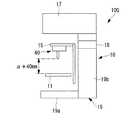
投光管17は、フレーム19の胴部19bの上端部に設けられ、ステージ11の上方に張り出すように配置されている。投光管17とフレーム19の胴部19bの上端部との間には、所定の厚さ寸法を有する嵩上げ部材18が着脱可能に設けられている。嵩上げ部材18を着脱することにより、アーム15の基準位置および投光管17の高さを調整することができるようになっている。 The
対物レンズユニット20,30,40,50としては、例えば、図2に示すようなイメージング用の対物レンズユニット20と、図3〜図5に示すようなパッチクランプ用あるいは生体の生きたまま(IN VIVO)の観察用の対物レンズユニット30,40,50等が挙げられる。 As the
イメージング用の対物レンズユニット20は、図2に示すように、顕微鏡本体10のアーム15に取り付け可能なレボルバ(装着装置)21と、レボルバ21に着脱可能な対物レンズ23とにより構成されている。 As shown in FIG. 2, the imaging
レボルバ21は、アーム15の上下動により、対物レンズ23の光軸方向(Z軸方向)に動作可能となっている。また、レボルバ21は、所定の回転軸(図示略)回りに回転可能に設けられ、周方向に沿って間隔をあけて複数の対物レンズ23を同時に装着することができるようになっている。図2では、レボルバ21に対物レンズ23が1つ装着されている。このレボルバ21は、回転軸回りに回転することにより、複数の対物レンズ23のいずれか1つを試料に対向する位置に択一的に配置することができるようになっている。The
また、レボルバ21は、アーム15に対する取付位置21aから対物レンズ23の装着位置21bまでの距離が寸法Cに設定されている。レボルバ21に装着される複数の対物レンズ23は、レボルバ21における各対物レンズ23の装着位置21bから各対物レンズ23の焦点位置までの距離(以下、レボルバ21における対物レンズ23の装着位置21bから対物レンズ23の焦点位置までの距離を「同焦距離」という。)が寸法Eになるように、それぞれの長さ寸法が設定されている。 In the
また、レボルバ21は、微分干渉観察にも対応しており、微分干渉観察法(DIC:Differential Interference Contrast)で用いる微分干渉用プリズムユニットとしてのDICスライダ1が着脱可能に設けられている。DICスライダ1は、レボルバ21に対して水平に装着され、DICスライダ1内に設けられた微分干渉用プリズムとしてのDICプリズム(図示略)が、対物レンズ23の瞳位置近傍に配置されるようになっている。 The
パッチクランプ用あるいはIN VIVO用の対物レンズユニット30,40,50は以下の通りである。
対物レンズユニット30は、図3に示すように、顕微鏡本体10のアーム15に取り付け可能なノーズピース(装着装置)31と、ノーズピース31に着脱可能な対物レンズ33とにより構成されている。The
As shown in FIG. 3, the
ノーズピース31は、XY軸方向に延びる所定の揺動軸回りに揺動可能な揺動部35を備えている。揺動部35には、その揺動方向に沿って間隔をあけて複数の対物レンズ33を同時に装着することができるようになっている。図3では、ノーズピース31に対物レンズ33が2つ装着されている。このノーズピース31は、揺動部35を揺動軸回りに揺動させることにより、複数の対物レンズ33のいずれか1つを試料に対向する位置に択一的に配置することができるようになっている。The
また、ノーズピース31は、アーム15に対する取付位置31aから対物レンズ33の装着位置31bまでの距離が寸法Cに設定されている。ノーズピース31に装着される複数の対物レンズ33は、ノーズピース31における各対物レンズ33の装着位置31bから各対物レンズ33の焦点位置までの距離(以下、ノーズピース31における対物レンズ31の装着位置31bから対物レンズ33の焦点位置までの距離を「同焦距離」という。)が寸法Eになるように、それぞれの長さ寸法が設定されている。Further, in the
次に、対物レンズユニット40は、図4に示すように、顕微鏡本体10のアーム15に取り付け可能なスライド式のノーズピース(装着装置)41と、ノーズピース41に着脱可能な対物レンズ43とにより構成されている。ノーズピース41は、XY軸方向にスライド可能に設けられ、スライド方向に沿って間隔をあけて複数の対物レンズ43を同時に装着することができるようになっている。このノーズピース41は、スライドすることにより、複数の対物レンズ43のいずれか1つを試料に対向する位置に択一的に配置することができるようになっている。Next, as shown in FIG. 4, the
また、ノーズピース41は、アーム15に対する取付位置41aから対物レンズ43の装着位置41bまでの距離が寸法Cに設定されている。図4では、ノーズピース41に対物レンズ43が2つ装着されている。一方の対物レンズ43は、ノーズピース41における装着位置41bとの間に配置される対物アダプタ45を備えている。一方の対物レンズ43においては、ノーズピース41における装着位置41bとの間に対物アダプタ45を介在させるだけの簡易な構成で、他方の対物レンズ43との同焦距離を一致させることができる。In the
これにより、一方の対物レンズ43の長さ寸法を調整し、ノーズピース41におけるこれら2つの対物レンズ43の装着位置41bから各対物レンズ43の焦点位置までの距離(以下、ノーズピース41における対物レンズ43の装着位置41bから対物レンズ41の焦点位置までの距離を「同焦距離」という。)がそれぞれ寸法Eになるように設定されている。Thereby, the length dimension of one
次に、対物レンズユニット50は、図5に示すように、顕微鏡本体10のアーム15に取り付け可能なノーズピース(装着装置)51と、ノーズピース51に着脱可能な対物レンズ53とにより構成されている。ノーズピース51は、対物レンズ53が装着されるノーズピース本体(装着装置本体)55Aと、ノーズピース本体55Aに固定され、ノーズピース本体55Aをアーム15における取付位置15aに着脱可能に取り付ける装着アダプタ55Bとを有している。Next, as shown in FIG. 5, the
ノーズピース本体55Aは、所定の回転軸(図示略)回りに回転可能に設けられ、周方向に沿って間隔をあけて複数の対物レンズ53を同時に装着することができるようになっている。図5では、ノーズピース本体55Aに対物レンズ53が1つ装着されている。このノーズピース51は、ノーズピース本体55Aが回転軸回りに回転することにより、複数の対物レンズ53のいずれか1つを試料に対向する位置に択一的に配置することができるようになっている。 The nosepiece
このノーズピース本体55Aは、ノーズピース31やノーズピース41の厚さ寸法よりも小さい厚さ寸法Aを有している。装着アダプタ55Bは、ノーズピース本体55Aの厚さ寸法とノーズピース31およびノーズピース41の厚さ寸法との差分に相当する厚さ寸法Bを有している。これにより、ノーズピース51は、アーム15に対する取付位置51aから対物レンズ53の装着位置51bまでの距離が寸法Cに設定されている。したがって、ノーズピース51は、アーム15における取付位置15aとノーズピース本体55Aとの間に装着アダプタ55Bを介在させることで、単体からなるノーズピース31,41との寸法差を補うようになっている。 The nosepiece body 55 </ b> A has a thickness dimension A that is smaller than the thickness dimension of the
ノーズピース51に装着される複数の対物レンズ53は、ノーズピース51における各対物レンズ53の装着位置51bから各対物レンズ53の焦点位置までの距離(以下、ノーズピース51における対物レンズ51の装着位置51bから対物レンズ51の焦点位置までの距離を「同焦距離」という。)が寸法Eになるように、それぞれの長さ寸法が設定されている。 The plurality of
これらパッチクランプ用あるいはIN VIVO用の対物レンズユニット30,40,50もアーム15の上下動により、各対物レンズ33,43,53の光軸方向(Z方向)に動作可能となっている。また、対物レンズユニット30,40,50も微分干渉観察に対応しており、レボルバ21と同様に、各ノーズピース31,41,51にDICスライダ1が着脱可能に設けられている。 The
上記すべての対物レンズユニット20,30,40,50は、顕微鏡本体10のアーム15に対するレボルバ21またはノーズピース31,41,51の各取付位置21a,31a,41a,51a、すなわち、アーム15における取付位置15aから各対物レンズ23,33,43,53の焦点位置までの距離が同一寸法(寸法C+寸法E)に設定されている。 All the
次に、このように構成された顕微鏡セット100の作用について説明する。
本実施形態に係る顕微鏡セット100により、イメージング用の対物レンズユニット20を用いて、スライドガラスやディッシュにより保持された細胞等の試料を観察する場合は、図6に示すように、嵩上げ部材18は外し、フレーム19のベース部19a上にコンデンサホルダ14を介さずにコンデンサ13を配置する。Next, the operation of the microscope set 100 configured as described above will be described.
When observing a sample such as a cell held by a slide glass or a dish using the imaging
また、ステージ11とコンデンサ13との間の距離がβとなるように、ステージ11の高さを設定する。さらに、顕微鏡本体10に対物レンズユニット20を取り付け、レボルバ21により、いずれかの対物レンズ23を試料の真上に配置する。アーム15が基準位置のときの対物レンズ23の先端からステージ11までの距離をαとする。 Further, the height of the
この状態で、透過照明用の光源から照明光を発生させ、コンデンサ13により試料に照明光を照射する。ステージ11の下方から照明光が照射されることにより、試料を透過した透過光(検出光)は、対物レンズ23により集光されて検出部により検出される。これにより、試料を観察することができる。In this state, to generate the illumination light from the light source fortransparently lighting, applying illumination light to the sample by the
この場合において、対物レンズユニット20に装着される複数の対物レンズ23のレボルバ21における装着位置21bから焦点位置までの距離を同一に設定しているので、対物レンズユニット20内で、対物レンズ23を倍率が異なる他の対物レンズ23に同焦距離を保ったまま容易に切り替えることができる。 In this case, since the distance from the mounting
次に、イメージング用の対物レンズユニット20からパッチクランプ用あるいはIN VIVO用の対物レンズユニット30,40,50に切り替えて、スライドガラスやディッシュにより保持された細胞等の試料を観察する場合は、図7に示すように、嵩上げ部材18を装着し、アーム15の基準位置および投光管17を嵩上げする。また、フレーム19のベース部19a上にコンデンサホルダ14を設けて、コンデンサホルダ14によりコンデンサ13を支持させる。また、ステージ11とコンデンサ13との間の距離がβとなるように、ステージ11の高さを設定する。 Next, when the
例えば、対物レンズユニット30を用いるとすると、アーム15をステージ11から離間させて対物レンズユニット20を外し、アーム15に対物レンズユニット30を取り付ける。そして、ノーズピース31により、いずれかの対物レンズ33を試料の真上に配置する。嵩上げ部材18を装着してアーム15を嵩上げしたことにより、コンデンサホルダ14を設けても、アーム15が基準位置のときの対物レンズ33の先端からステージ11までの距離がαとなる。 For example, if the
この場合において、アーム15に対するレボルバ21の取付位置21aから対物レンズ23の焦点位置までの距離と、アーム15に対するノーズピース31の取付位置31aから対物レンズ33の焦点位置までの距離を同一に設定しているので、対物レンズユニット20,30の切替時に、スペースを確保するために昇降機構16により対物レンズユニット20を光軸方向に移動させても、切替前の対物レンズユニット20の同焦距離と、切替後の対物レンズユニット30の同焦距離を簡易に保つことができる。 In this case, the distance from the mounting
この状態で、透過照明用の光源から照明光を発生させてコンデンサ13により試料に照明光を照射し、試料を透過した透過光を対物レンズ33により集光させて検出部により検出する。これにより、試料を観察することができる。対物レンズユニット30を用いる場合を例示して説明したが、対物レンズユニット40,50を用いる場合も同様である。In this state, illumination light is generated from a light source for transmission illumination, the sample is irradiated with illumination light by the
この場合も同様に、対物レンズユニット30に装着される複数の対物レンズ33のノーズピース31における装着位置31bから焦点位置までの距離を同一に設定しているので、対物レンズユニット30内で、対物レンズ33を倍率が異なる他の対物レンズ33に同焦距離を保ったまま容易に切り替えることができる。 In this case as well, since the distance from the mounting
次いで、パッチクランプ用あるいはIN VIVO用の対物レンズユニット30,40,50を用いて、スライドガラスやディッシュにより保持された細胞等の試料に代えて、試料として比較的小さい小動物を観察する場合は、図8に示すように、嵩上げ部材18を装着したままで、フレーム19のベース部19a上からコンデンサホルダ14およびコンデンサ13を外す。 Next, when observing a relatively small small animal as a sample instead of a sample such as a cell held by a slide glass or a dish using the
そして、例えば、対物レンズユニット30に代えて対物レンズユニット40を用いるとすると、アーム15をステージ11から離間させて対物レンズユニット30を外し、アーム15に対物レンズユニット40を取り付ける。ノーズピース41により、いずれかの対物レンズ43を試料の真上に配置する。試料の大きさに合わせてステージ11と対物レンズ43とのスペースを確保するため、ステージ11と対物レンズ43の先端との間の距離が例えばα+40mmとなるように、ステージ11の高さを設定する。 For example, when the
この場合も同様に、アーム15に対するノーズピース31の取付位置31aから対物レンズ33の焦点位置までの距離と、アーム15に対するノーズピース41の取付位置41aから対物レンズ43の焦点位置までの距離を同一に設定しているので、切替前の対物レンズユニット30の同焦距離と、切替後の対物レンズユニット40の同焦距離を簡易に保つことができる。 In this case as well, the distance from the
この状態で、落射照明用の光源から照明光を発生させ、投光管17の照明光学系を介して対物レンズ43により試料に照明光を照射する。照明光が照射されることにより試料から戻る戻り光(検出光)は、対物レンズ43により集光されて検出部により検出される。これにより、試料を観察することができる。対物レンズユニット40を用いる場合を例示して説明したが、対物レンズユニット30,50を用いる場合も同様である。In this state, illumination light is generated from a light source for epi-illumination, and the sample is irradiated with illumination light by the
この場合も同様に、対物レンズユニット40に装着される複数の対物レンズ43のノーズピース41における装着位置41bから焦点位置までの距離を同一に設定しているので、対物レンズユニット40内で、対物レンズ43を倍率が異なる他の対物レンズ43に同焦距離を保ったまま容易に切り替えることができる。 In this case as well, since the distance from the mounting
次いで、パッチクランプ用あるいはIN VIVO用の対物レンズユニット30,40,50を用いて、試料として比較的小さい小動物に代えて比較的大きい小動物を観察する場合は、図9に示すように、嵩上げ部材18を装着したままで、また、コンデンサホルダ14およびコンデンサ13を外したままで、試料の大きさに合わせて、ステージ11の高さを下げる。 Next, when observing a relatively large small animal instead of a relatively small small animal as a sample using the patch clamp or IN VIVO
例えば、対物レンズユニット40に換えて対物レンズユニット50を用いるとすると、アーム15をステージ11から離間させて対物レンズユニット40を外し、アーム15に対物レンズユニット50を取り付ける。そして、ノーズピース51により、対物レンズ53のいずれかを試料の真上に配置する。試料の大きさに合わせて、ステージ11と対物レンズ53とのスペースを確保するため、ステージ11と対物レンズ53の先端との間の距離がα+(40+50)mmとなるように、ステージ11の高さを設定する。 For example, if the
この場合も同様に、アーム15に対するノーズピース41の取付位置41aから対物レンズ43の焦点位置までの距離と、アーム15に対するノーズピース51の取付位置51aから対物レンズ53の焦点位置までの距離を同一に設定しているので、切替前の対物レンズユニット40の同焦距離と、切替後の対物レンズユニット50の同焦距離を簡易に保つことができる。 In this case as well, the distance from the
この状態で、落射照明用の光源から照明光を発生させて、投光管17の照明光学系を介して対物レンズ53により試料に照射し、試料から戻る戻り光を対物レンズ53により集光させて検出部により検出する。これにより、試料を観察することができる。対物レンズユニット50を用いる場合を例示して説明したが、対物レンズユニット30,40を用いる場合も同様である。In this state, illumination light is generated from a light source for epi-illumination, the sample is irradiated onto the sample by the
この場合も同様に、対物レンズユニット50に装着される複数の対物レンズ53のノーズピース51における装着位置51bから焦点位置までの距離を同一に設定しているので、対物レンズユニット50内で、対物レンズ53を倍率が異なる他の対物レンズ53に同焦距離を保ったまま容易に切り替えることができる。 In this case as well, the distances from the mounting
以上説明したように、本実施形態における顕微鏡セット100によれば、対物レンズユニット20,30,40,50どうしの顕微鏡本体10に対するレボルバ21あるいはノーズピース31,41,51の各取付位置21a,31a,41a,51aから各対物レンズ23,33,43,53の焦点位置までの距離を同一に設定することで、対物レンズユニット20,30,40,50の切替時に、スペースを確保するために昇降機構16により対物レンズユニット20,30,40,50を光軸方向に移動させても、切替前の対物レンズユニット20,30,40,50の同焦距離と切替後の対物レンズユニット20,30,40,50の同焦距離を簡易に保つことができる。したがって、複数の対物レンズユニット20,30,40,50間における対物レンズ23,33,43,53の同焦距離を保ちながら、これら対物レンズユニット20,30,40,50を選択的に交換して用いることができる。 As described above, according to the microscope set 100 in the present embodiment, the
本実施形態においては、対物レンズ43が対物アダプタ45を備えることとしたが、他の対物レンズ23,33,53が対物アダプタを備えることにより、同一の対物レンズユニット20,30,50内の複数の対物レンズ23,33,53の同焦距離が一致するように、その長さを調整することとしてもよい。 In the present embodiment, the
また、本実施形態においては、対物レンズユニット50のノーズピース51が装着アダプタ55を備えることとしたが、例えば、対物レンズユニット20のレボルバ21、対物レンズユニット30のノーズピース31、対物レンズユニット40のノーズピース41のいずれかが接着アダプタを備えることとしてもよい。In the present embodiment, the
10 顕微鏡本体
20,30,40,50 対物レンズユニット
21 レボルバ(装着装置)
21a 取付位置
23 対物レンズ
31 ノーズピース(装着装置)
31a 取付位置
33 対物レンズ
41 ノーズピース(装着装置)
41a 取付位置
43 対物レンズ
51 ノーズピース(装着装置)
51a 取付位置
53 対物レンズ
55B 装着アダプタ
100 顕微鏡セット
10
Claims (3)
Translated fromJapanese該顕微鏡本体に対して選択的に取り付けられる着脱可能な複数の対物レンズユニットとを備える顕微鏡セットであって、
前記顕微鏡本体が、取り付けられた前記対物レンズユニットを光軸方向に移動可能な昇降機構を備え、
前記複数の対物レンズユニットが、前記顕微鏡本体に取り付け可能な装着装置と、該装着装置に着脱可能に装着され、前記顕微鏡本体から発せられた照明光を前記試料に照射する一方、該試料からの検出光を集光する複数の対物レンズとを有し、
前記複数の対物レンズユニットが、前記装着装置に装着された前記複数の対物レンズを前記光軸に垂直な揺動軸回りに揺動させること、または前記装着装置に装着された前記複数の対物レンズを前記光軸に垂直な方向にスライドさせることにより、前記複数の対物レンズのいずれか1つを前記照明光の光路上に選択的に配置可能な第1の対物レンズユニットと、
前記装着装置に装着された前記複数の対物レンズを所定の回転軸回りに回転させることにより、前記複数の対物レンズのいずれか1つを前記照明光の光路上に選択的に配置可能な第2の対物レンズユニットとを含み、
前記第2の対物レンズユニットが、前記対物レンズが装着される前記装着装置の本体に固定される装着アダプタを介して、前記顕微鏡本体に着脱可能に取り付けられ、
前記顕微鏡本体側における前記第1の対物レンズユニットの取り付け位置から前記照明光の光路上に配置される前記第1の対物レンズユニットに取り付けられた前記対物レンズの焦点位置までの距離と、前記顕微鏡本体側における前記第2の対物レンズユニットの取り付け位置から前記照明光の光路上に配置される前記第2の対物レンズユニットに取り付けられた前記対物レンズの焦点位置までの距離とが同一に設定されている顕微鏡セット。A microscope body that generates illumination light to irradiate the sample and detects detection light from the sample;
A microscope set comprising a plurality of detachable objective lens units that are selectively attached to the microscope body,
The microscope body includes a lifting mechanism capable of moving the attached objective lens unit in the optical axis direction,
The plurality of objective lens units are attached to the microscope main body, and are detachably attached to the mounting apparatus, and irradiates the sample with illumination light emitted from the microscope main body. Aplurality of objective lenses that collect the detection light;
The plurality of objective lens units swings the plurality of objective lenses mounted on the mounting device around a swing axis perpendicular to the optical axis, or the plurality of objective lenses mounted on the mounting device. A first objective lens unit capable of selectively disposing any one of the plurality of objective lenses on the optical path of the illumination light by sliding in a direction perpendicular to the optical axis;
The second objective lens can be selectively arranged on the optical path of the illumination light by rotating the objective lenses mounted on the mounting device around a predetermined rotation axis. Objective lens unit, and
The second objective lens unit is detachably attached to the microscope main body via a mounting adapter fixed to the main body of the mounting device on which the objective lens is mounted.
Distance to the focal positionbefore Symbolsaid first of said objective lenswhich is attached to the objective lens unit from the preparativeInstallingRi position ofthe first objective lens unit in the microscope main bodysideis disposed on the optical path of the illumination lightWhenthe distancefrom the mounting position of the second objective lens unit in the microscope main body side to thefocal position of the objective lens attached to the second objective lens unit disposed on an optical path of the illumination light A set of microscopes set identically.
前記投光管と前記フレーム部との間に、所定の厚さ寸法を有する嵩上げ部材が着脱可能に設けられている請求項1または2に記載の顕微鏡セット。The microscope set according to claim 1, wherein a raising member having a predetermined thickness dimension is detachably provided between the light projecting tube and the frame portion.
Priority Applications (2)
| Application Number | Priority Date | Filing Date | Title |
|---|---|---|---|
| JP2011159301AJP5806537B2 (en) | 2011-07-20 | 2011-07-20 | Microscope set |
| US13/549,644US9250433B2 (en) | 2011-07-20 | 2012-07-16 | Microscope system with plural attachable/detachable objective lens units |
Applications Claiming Priority (1)
| Application Number | Priority Date | Filing Date | Title |
|---|---|---|---|
| JP2011159301AJP5806537B2 (en) | 2011-07-20 | 2011-07-20 | Microscope set |
Publications (2)
| Publication Number | Publication Date |
|---|---|
| JP2013025046A JP2013025046A (en) | 2013-02-04 |
| JP5806537B2true JP5806537B2 (en) | 2015-11-10 |
Family
ID=47555592
Family Applications (1)
| Application Number | Title | Priority Date | Filing Date |
|---|---|---|---|
| JP2011159301AActiveJP5806537B2 (en) | 2011-07-20 | 2011-07-20 | Microscope set |
Country Status (2)
| Country | Link |
|---|---|
| US (1) | US9250433B2 (en) |
| JP (1) | JP5806537B2 (en) |
Families Citing this family (4)
| Publication number | Priority date | Publication date | Assignee | Title |
|---|---|---|---|---|
| DE102014209308B4 (en)* | 2014-05-16 | 2016-12-15 | Trumpf Werkzeugmaschinen Gmbh + Co. Kg | Laser processing head with lens change system |
| DE102014114467A1 (en)* | 2014-10-06 | 2016-04-07 | Leica Microsystems (Schweiz) Ag | Microscope with oversized zoom system |
| CN113049592B (en)* | 2021-03-26 | 2022-04-15 | 湖南师范大学 | Bile duct cancer cell proliferation observation equipment |
| JP7696755B2 (en)* | 2021-05-25 | 2025-06-23 | 株式会社エビデント | Observation equipment |
Family Cites Families (13)
| Publication number | Priority date | Publication date | Assignee | Title |
|---|---|---|---|---|
| US5337177A (en) | 1989-09-13 | 1994-08-09 | Nikon Corporation | Microscope |
| JPH03100509A (en)* | 1989-09-13 | 1991-04-25 | Nikon Corp | microscope |
| DE4245060B4 (en)* | 1992-09-19 | 2007-12-06 | Leica Microsystems Cms Gmbh | Modular microscope system |
| JP3123457B2 (en)* | 1996-05-13 | 2001-01-09 | 株式会社ニコン | microscope |
| JPH10339845A (en)* | 1997-06-09 | 1998-12-22 | Olympus Optical Co Ltd | Monitor observation type microscope |
| US6226118B1 (en)* | 1997-06-18 | 2001-05-01 | Olympus Optical Co., Ltd. | Optical microscope |
| JP3900664B2 (en) | 1997-09-26 | 2007-04-04 | 株式会社ニコン | microscope |
| JP4128259B2 (en)* | 1998-03-17 | 2008-07-30 | オリンパス株式会社 | Optical element switching device |
| JP4814417B2 (en)* | 1999-09-16 | 2011-11-16 | オリンパス株式会社 | Objective lens switching device |
| US7345814B2 (en)* | 2003-09-29 | 2008-03-18 | Olympus Corporation | Microscope system and microscope focus maintaining device for the same |
| DE102007042260B4 (en)* | 2007-09-06 | 2012-09-27 | Leica Microsystems Cms Gmbh | Objective changer and a microscope |
| DE102009029146B4 (en)* | 2009-06-16 | 2014-04-24 | Leica Microsystems Cms Gmbh | Objective changer and microscope with such a lens changer |
| US8072699B2 (en)* | 2009-06-17 | 2011-12-06 | Semicaps Pte Ltd | Solid immersion lens optics assembly |
- 2011
- 2011-07-20JPJP2011159301Apatent/JP5806537B2/enactiveActive
- 2012
- 2012-07-16USUS13/549,644patent/US9250433B2/enactiveActive
Also Published As
| Publication number | Publication date |
|---|---|
| JP2013025046A (en) | 2013-02-04 |
| US20130021663A1 (en) | 2013-01-24 |
| US9250433B2 (en) | 2016-02-02 |
Similar Documents
| Publication | Publication Date | Title |
|---|---|---|
| JP6009862B2 (en) | Scanning probe microscope | |
| JP5779597B2 (en) | Use of microscope structural units, microscope devices and microscope structural units | |
| JP5806537B2 (en) | Microscope set | |
| JPWO2009031477A1 (en) | Autofocus device and microscope | |
| JP6280770B2 (en) | measuring device | |
| JP2008064977A (en) | Microscope apparatus control method and microscope apparatus | |
| JP2005128493A5 (en) | ||
| CN105136063A (en) | Microscope binocular stereo vision measurement device based on telecentric objectives | |
| JPH08114751A (en) | Optical microscope | |
| JP2022064854A5 (en) | ||
| CN108593648B (en) | 3D microstructure observation device and observation method thereof | |
| US9052509B2 (en) | Microscope system including detachable stage and detachable transmitted illumination optical system | |
| US7463414B2 (en) | Microscope | |
| JP2016535303A (en) | Objective lens changer | |
| JPWO2017086287A1 (en) | Shielding device, microscope, and observation method | |
| JP4928638B2 (en) | microscope | |
| JP6249681B2 (en) | Microscope system and measuring method | |
| JP4254229B2 (en) | Upright microscope | |
| JP6641177B2 (en) | Microscope system, microscope system control method and program | |
| CN113885187A (en) | Digital Microscopes and Microscopy Kits | |
| CN105765439B (en) | Movable objective lens arrangement | |
| CN111272771B (en) | High-resolution particle detection device | |
| JP2006153575A (en) | Three-dimensional measuring instrument | |
| JPH07333507A (en) | Microscope system | |
| JP5010929B2 (en) | Microscope equipment |
Legal Events
| Date | Code | Title | Description |
|---|---|---|---|
| A621 | Written request for application examination | Free format text:JAPANESE INTERMEDIATE CODE: A621 Effective date:20140709 | |
| A977 | Report on retrieval | Free format text:JAPANESE INTERMEDIATE CODE: A971007 Effective date:20150216 | |
| A131 | Notification of reasons for refusal | Free format text:JAPANESE INTERMEDIATE CODE: A131 Effective date:20150303 | |
| A521 | Request for written amendment filed | Free format text:JAPANESE INTERMEDIATE CODE: A523 Effective date:20150501 | |
| TRDD | Decision of grant or rejection written | ||
| A01 | Written decision to grant a patent or to grant a registration (utility model) | Free format text:JAPANESE INTERMEDIATE CODE: A01 Effective date:20150901 | |
| A61 | First payment of annual fees (during grant procedure) | Free format text:JAPANESE INTERMEDIATE CODE: A61 Effective date:20150904 | |
| R151 | Written notification of patent or utility model registration | Ref document number:5806537 Country of ref document:JP Free format text:JAPANESE INTERMEDIATE CODE: R151 | |
| S531 | Written request for registration of change of domicile | Free format text:JAPANESE INTERMEDIATE CODE: R313531 | |
| R350 | Written notification of registration of transfer | Free format text:JAPANESE INTERMEDIATE CODE: R350 | |
| R250 | Receipt of annual fees | Free format text:JAPANESE INTERMEDIATE CODE: R250 | |
| R250 | Receipt of annual fees | Free format text:JAPANESE INTERMEDIATE CODE: R250 | |
| R250 | Receipt of annual fees | Free format text:JAPANESE INTERMEDIATE CODE: R250 | |
| R250 | Receipt of annual fees | Free format text:JAPANESE INTERMEDIATE CODE: R250 | |
| R250 | Receipt of annual fees | Free format text:JAPANESE INTERMEDIATE CODE: R250 | |
| S111 | Request for change of ownership or part of ownership | Free format text:JAPANESE INTERMEDIATE CODE: R313111 | |
| R371 | Transfer withdrawn | Free format text:JAPANESE INTERMEDIATE CODE: R371 | |
| S111 | Request for change of ownership or part of ownership | Free format text:JAPANESE INTERMEDIATE CODE: R313111 | |
| R371 | Transfer withdrawn | Free format text:JAPANESE INTERMEDIATE CODE: R371 | |
| S111 | Request for change of ownership or part of ownership | Free format text:JAPANESE INTERMEDIATE CODE: R313111 | |
| R350 | Written notification of registration of transfer | Free format text:JAPANESE INTERMEDIATE CODE: R350 | |
| R250 | Receipt of annual fees | Free format text:JAPANESE INTERMEDIATE CODE: R250 | |
| R250 | Receipt of annual fees | Free format text:JAPANESE INTERMEDIATE CODE: R250 | |
| R250 | Receipt of annual fees | Free format text:JAPANESE INTERMEDIATE CODE: R250 |